

Page 1
OPERATION
MANUAL
MFR-5000
Multi Format Routing Switcher
MFR-18/39RUA
MFR-16/18/39/40RU
MFR-16RUD
MFR-16/32/64RUW
MFR-16RUTA
MFR-GPI
MFR-TALM
13th Edition - Rev. 1
Page 2
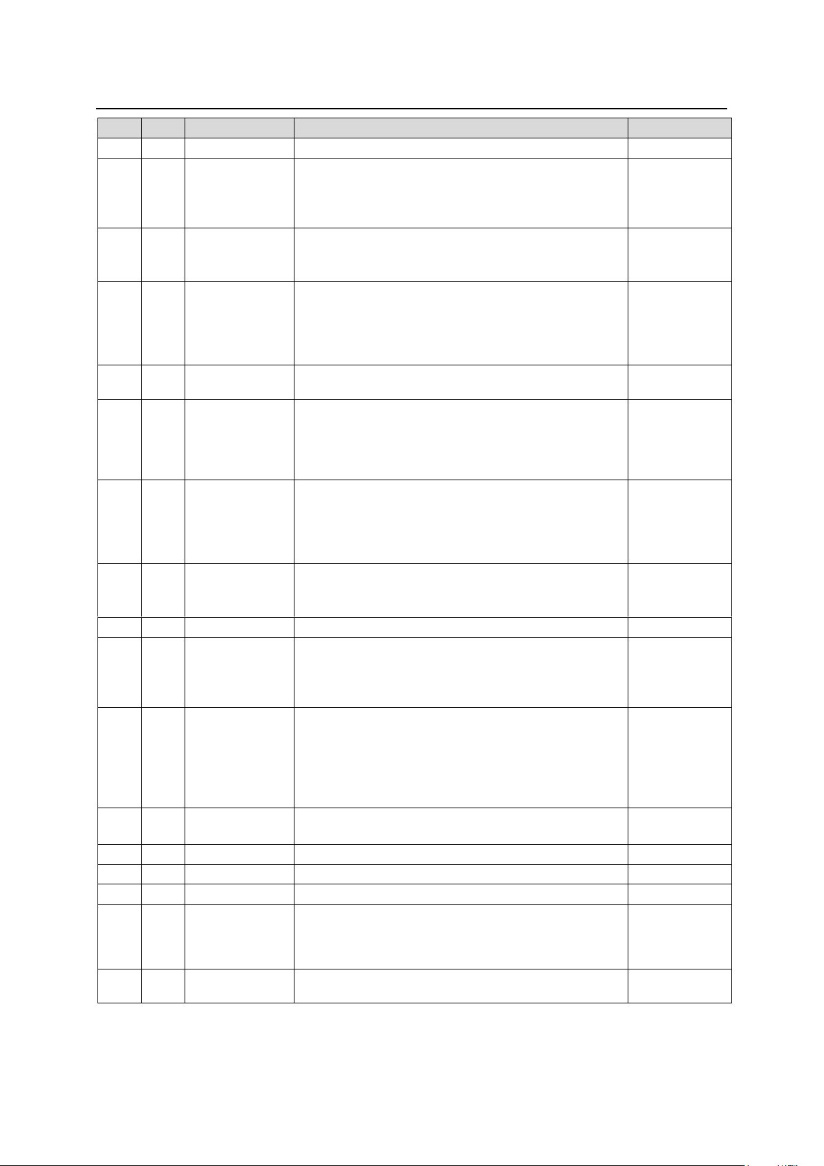
Edition Revision History
Edit.
Rev.
Date
Description
Section/Page
1 - 2011/11/07
2
|
5
-
(Not released)
Added MFR-16ADI/16ADAO option cards.
Added MFR-18RU.
Added MFR-16RU.
Added MFR-GUI.
6 - 2013/05/22
Added MFR-16AAI/AESI/AESO option cards.
Added MFR-16RUD
Added MFR-TALM.
7 - 2013/08/13
Added MFR-16RUW/32RUW remote units
Changed DC cable retaining clamps
Added Setup menu for RU
Factual errors corrected
p 6
Sec. 5-6
Sec. 5-7
7 1 2013/08/21
Changed power consumption for MFR-GPI,
MFR-16RUD/16RUW/32RUW
Sec. 9-1
7 2 2013/09/10
Manuals supplied on CD-ROM
Changed Setup menu description
Changed MFR-16RUW/32RUW front panels
p 5
Sec. 5-7
Sec. 5-8
Sec. 9-2-7
Sec. 9-2-8
8 - 2013/12/25
Added Main Unit Link function
Added MFR-64RUW.
RU current level is applied to RU Salvos.
Added Group LOCK OTHER function.
3-2
2-2, 9-1-8,
9-2-7, etc.
6-2-2
6-3-2
8 1 2014/03/20
Added CPU2 condition display
Added the max. number of LAN/Serial connections.
Corrected factual errors.
p 22, 49, 52
p 98
9
(Not Rereaced)
9 1 2014/10/24
Supported MFR-16DTIO cards
Enabled group button assignments
Added 2-way Lock buttons (by short and long press)
Added serial control commands.
Sec. 2, 9-1-1
Sec. 5-2-2
Sec. 5-3 to 5-5
Sec. 7-3
10 - 2015/04/06
MFR-16RUTA supported
Changed control command description
Added text color tuning for remote control unit
buttons.
Notes on button labels deletec (uploaded to the HP)
Corrected factual errors.
Sec. 7-3
Sec. 8
Appendix
11 - 2015/06/26
Added Switcher's AUX Crosspoints Switching.
Added Destination Lock Status Request Command.
Sec. 3-4
Sec. 7-3-5
12 - 2015/11/11
MFR-18/39RUA supported.
12 1 2016/04/01
LAN control command added (signal name import)
Sec. 7-3
12 2 2016/09/06
Changed control command description
Sec. 7-3
13 - 2017/02/22
Switcher AUX switching supported (HVS-100/110,
HVS-2000).
Gearbox (MFR-16SDIGB/SDOGB) supported.
Secs. 3-3, 3-4
Secs. 2-1, 2-2,
2-3, 8
13 1 2017/03/01
MFR-16AAIEX/AAOEX suppoerted.
Secs. 2-1, 2-2,
2-4
2
Page 3

Main Unit Firmware Version (*1)
GUI Version
(*2)
Supported
Hardware
Supported Feature
MFR-5000
1.62 or higher
1.63 or higher
MFR-64RUW
Main Unit Link
1.72 or higher
1.77 or higher
MFR-16RUTA
-
1.76 or higher
1.85 or higher
-
-MU link of MFR-8000
and 5000
-Switcher's AUX
Crosspoints Switching
1.79 or higher
1.91 or higher
-
-Import names
1.85 or higher
1.98.1 or higher
MFR-16AAIEX
MFR-16AAIOEX
-Analog audio
input/output
1.86 or higher
2.01 or higher
MFR-16SDIGB
MFR-16SDOGB
-Gearbox feature
Firmware / Software Versions and Supported Hardware / Features
(*1) Click [Primary CPU] in the [Web-based Control: System Settings- MU Info page] to see your version number
under Firmware Version.
(*2) The GUI (Web-based control software) version is displayed on the browser's title bar.
3
Page 4
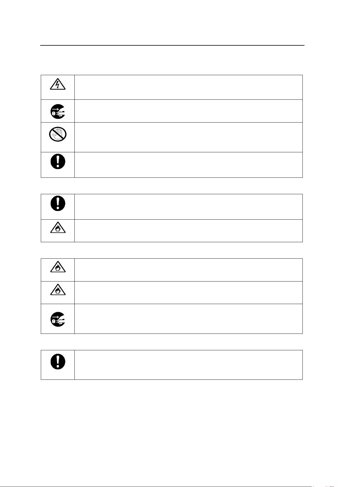
Precautions
Caution
Operate unit only at the specified supply voltage.
Disconnect the power cord via the power plug only. Do not pull on the cable portion.
Stop
Do not place or drop heavy or sharp-edged objects on the power cord. A damaged
cord can cause fire or electrical shock hazards. Regularly check the power cord for
excessive wear or damage to avoid possible fire / electrical hazards.
Caution
Ensure the power cord is firmly plugged into the AC outlet.
Caution
Ensure the unit is properly grounded at all times to prevent electrical shock.
Hazard
Do not ground the unit to gas lines, units, or fixtures of an explosive or dangerous
nature.
Hazard
Do not operate the unit under hazardous or potentially explosive atmospheric
conditions. Doing so could result in fire, explosion, or other hazardous results.
Hazard
Do not allow liquids, metal pieces, or other foreign materials to enter the unit. Doing
so could result in fire, other hazards, or a unit malfunction.
If a foreign material does enter the unit, turn the power off and immediately
disconnect the power cord. Remove the material and contact an authorized service
representative if damage has occurred.
Caution
Handle with care to avoid impact shock during transit, which may cause
malfunction. When you need to transport the unit, use the original or suitable
alternative packing material.
Important Safety Warnings
[Power]
[Grounding]
[Operation]
[Transportation]
4
Page 5
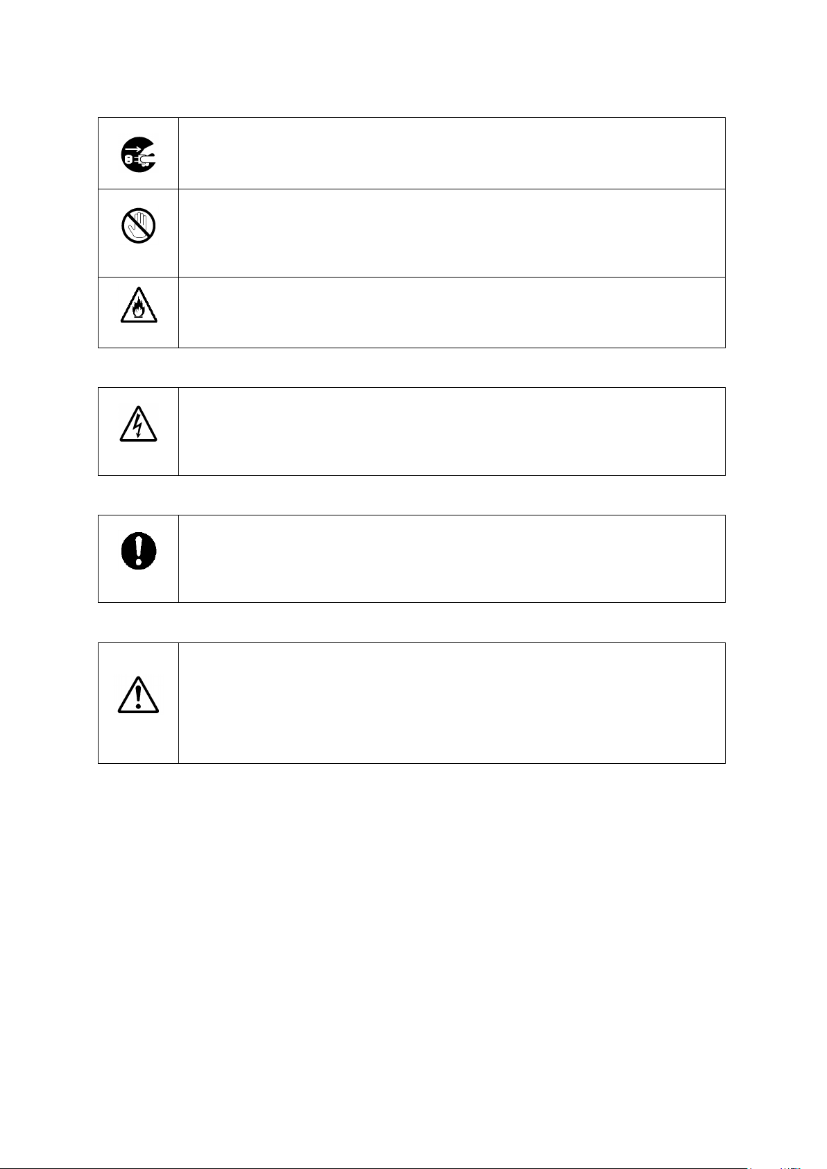
[Circuitry Access]
Do not remove covers, panels, casing, or access the circuitry with power applied to
the unit. Turn the power off and disconnect the power cord prior to removal. Internal
servicing / adjustment of unit should only be performed by qualified personnel.
Stop
Do not touch any parts / circuitry with a high heat factor.
Capacitors can retain enough electric charge to cause mild to serious shock, even
after the power has been disconnected. Capacitors associated with the power
supply are especially hazardous.
Hazard
Unit should not be operated or stored with cover, panels, and / or casing removed.
Operating the unit with circuitry exposed could result in electric shock / fire hazards
or a unit malfunction.
Caution
If abnormal odors or noises are noticed coming from the unit, immediately turn the
power off and disconnect the power cord to avoid potentially hazardous conditions.
If problems similar to the above occur, contact an authorized service representative
before attempting to operate the unit again.
Caution
To rack-mount or ground the unit, or to install rubber feet, do not use screws or
materials other than those supplied. Doing so may cause damage to the internal
circuits or components of the unit. If you remove the rubber feet that are attached to
the unit, do not reinsert the screws that secure the rubber feet.
Caution
Consumable items that are used in the unit must be periodically replaced. For
further details on which parts are consumables and when they should be replaced,
refer to the specifications at the end of the Operation Manual. Since the service life
of the consumables varies greatly depending on the environment in which they are
used, such items should be replaced at an early date. For details on replacing
consumable items, contact your dealer.
[Potential Hazards]
[Rack Mount Brackets, Ground Terminal, and Rubber Feet]
[Consumables]
5
Page 6
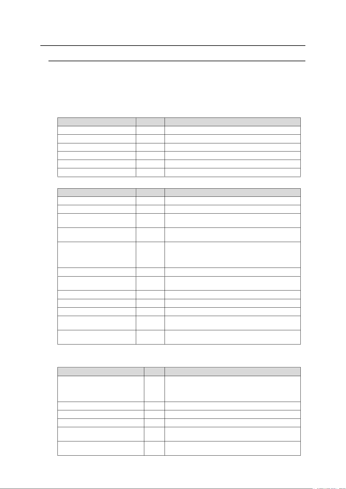
Upon Receipt
ITEM
QTY
REMARKS
MFR-5000
1
AC Cord
1 set
AC cable and retaining clip
Rack Mount Brackets
1 set
EIA standard type (Attached to unit.)
Power Switch Faceplate
1
Switch guard for MFR-PS.
CD-ROM
1
Operation manual (PDF)
Quick Setup Guide
1
ITEM
QTY
REMARKS
MFR-16SDI/16SDIA
1 – 8 *
16 SDI input card
MFR-16SDO
1 – 8 *
16 SDI output card
MFR-16ADI
1 – 4 *
Digital audio input card with SRC
(AES/EBU 16 stereo pairs)
MFR-16AAI
1 – 4 *
Analog audio input card with A/D converter
(Analog 16 stereo pairs)
MFR-16ADAO
1 – 8 *
Audio output card with D/A converter
(AES/EBU 8 stereo pairs)
(SDI x 2 8 stereo pairs)
(ANALOG 4 stereo pairs)
MFR-16AESI
1 – 8 *
Digital audio input card (AES/EBU 16 stereo pairs)
MFR-16AESO
1 – 8 *
Digital audio output card (AES/EBU 16 stereo
pairs)
MFR-16DTIO
1 – 8 *
Data Router card (9-pin D-sub x 16, RS-422)
MFR-16SDIGB
1 –
16 SDI input card (Gearbox 4ch built-in)
MFR-16SDOGB
1 –
16 SDI output card (Gearbox 4ch built-in)
MFR-16AAIEX
1 – 4 *
Analog audio input card with A/D converter
(Analog 16 stereo pairs)
MFR-16AAOEX
1 – 4 *
Analog audio output card with D/A converter
(Analog 16 stereo pairs)
ITEM
QTY
REMARKS
MFR-18RUA/39RUA
MFR-39RU/40RU/18RU
MFR-16RU/16RUD/16RUTA
MFR-16/32/64RUW
1
AC Adaptor
(*1)
1
With DC lock plug (MFR-40RU/39RUA/18RUA)
AC cable
1 DC cable retaining clip
1 set
For AC adapters w/o DC lock plug
Rack Mount Brackets
1 set
EIA standard type (MFR-16/32/64RUW/16RUTA is
supplied w/o Rack Mount Brackets.)
Tool used to change
button labels
1
Unpacking
MFR-5000 units and their accessories are fully inspected and adjusted prior to shipment.
Operation can be performed immediately upon completing all required connections and
operational settings.
Check your received items against the packing lists below. Check to ensure no damage has
occurred during shipment. If damage has occurred, or items are missing, inform your supplier
immediately.
Main Unit
Input / Output Cards
* The number of installed cards varies depending on the system configuration. See the Matrix Size Chart
on page 16.
Remote Control Panel
6
Page 7
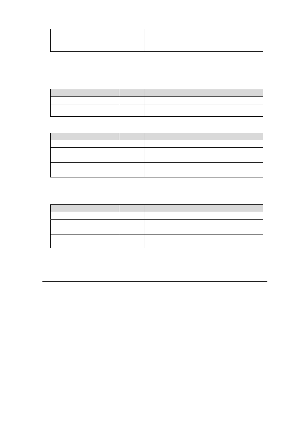
LAN Cable (straight)
(*2)
1
MFR-39/40/18RU/16RUTA/18RUA/39RUA:
UTP cable, 5m
MFR-16RU/16RUD: STP cable, 5m
(MFR-16/32/64RUW is supplied w/o LAN Cable.)
(*1) Depending on the production date, AC adapter is supplied without DC lock plug, but with a DC cable
ITEM
QTY
REMARKS
MFR-CPU
1
Redundant CPU card *
MFR-PS
1 set
Redundant power supply unit (with AC cord and AC
cord retaining clip.)
ITEM
QTY
REMARKS
MFR-GPI
1
AC Adaptor *
1
With DC lock plug
AC cable
1
Rack Mount Brackets
1 set
EIA standard type
LAN Cable (straight)
1
ITEM
QTY
REMARKS
MFR-TALM
1
AC Adaptor *
1
With DC lock plug
AC cable
1
Rack Mount Brackets
(optional)
1 set
Single- or Dual-unit type
EIA standard type
retaining clip.
(*2) User-prepared LAN cables are also available and Shielded Twist Pair cables are recommended for
MFR-16RU/16RUD/16RUW/32RUW/64RUW.
Option (for MFR-5000)
Interface Expansion Unit
* Depending on the production date, AC adapter is supplied without DC lock plug, but with a DC cable
retaining clip.
Tally Manager Unit
* Depending on the production date, AC adapter is supplied without DC lock plug, but with a DC cable
retaining clip.
Installing the AC Cord Retaining Clip (Main Unit)
Secure the AC cord with the supplied AC cord retaining clip to prevent accidental removal from
the unit.
Procedure
1) Securely plug the AC cord into the AC connector.
2) Attach the Retaining clip on to the side of the AC cord.
3) Thread both ends of the retaining clip into the holes of the retaining clip base attached on the
unit.
7
Page 8
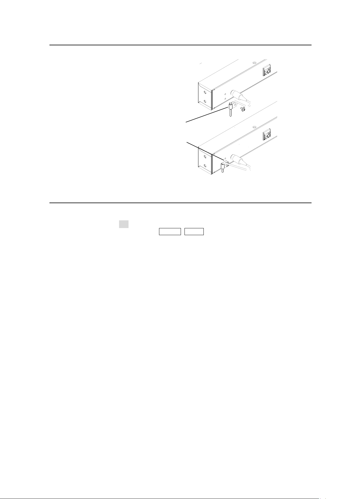
Installing the DC Cable Retaining Bracket
2) Secure the clip with
the supplied screw.
1) Bundle the cable with
the supplied clip.
Install the supplied retaining bracket onto the rear panel of devices, such as a Control Unit as
shown below.
Font Conventions
The following conventions are used throughout this manual:
Shaded text (such as ON) indicates parameter values in the menu.
Text enclosed by a square (such as ALARM, MODE) indicates front panel buttons on the
MFR-5000 or Remote Control Units.
References to the MFR Series Web-based Control Software are indicated by [Web-based
Control: XXX page].
8
Page 9

Table of Contents
1. Prior to Starting .......................................................................................................................... 14
1-1. Welcome ............................................................................................................................ 14
1-2. Features ............................................................................................................................. 14
2. Panel Descriptions .................................................................................................................... 15
2-1. MFR-5000 Front Panel ....................................................................................................... 15
2-1-1. Matrix Size Chart ......................................................................................................... 16
2-1-2. Input / Output Card Installation and Removal ............................................................. 17
2-1-3. CPU Card Installation and Removal ........................................................................... 18
2-1-4. CPU Card Switch Settings .......................................................................................... 20
2-2. MFR-5000 Rear Panel ....................................................................................................... 21
2-2-1. Interfaces..................................................................................................................... 22
2-3. SDI Input/Output Cards ...................................................................................................... 24
2-3-1. MFR-16SDI/16SDIA .................................................................................................... 24
2-3-2. MFR-16SDO ............................................................................................................... 24
2-3-3. MFR-16SDIGB ............................................................................................................ 25
2-3-4. MFR-16SDOGB .......................................................................................................... 25
2-4. Audio Input / Output Cards................................................................................................. 26
2-4-1. MFR-16AAI / 16AAIEX (Analog Input) ........................................................................ 26
2-4-2. MFR-16ADI (AES Input with SRC) ............................................................................. 30
2-4-3. MFR-16ADAO (Embedded / AES / Analog Output) ................................................... 31
2-4-4. MFR-16AESI (AES Input) ........................................................................................... 33
2-4-5. MFR-16AESO (AES Output)....................................................................................... 33
2-5. RS-422 Data Input / Output Cards ..................................................................................... 34
2-6. Remote Control Panel ........................................................................................................ 36
2-6-1. Front Panel .................................................................................................................. 36
2-6-2. Rear Panel .................................................................................................................. 40
2-7. MFR-GPI ............................................................................................................................ 41
2-7-1. Front Panel .................................................................................................................. 41
2-7-2. Rear Panel .................................................................................................................. 42
2-7-3. Interfaces (MFR-GPI) .................................................................................................. 43
2-7-4. Switches on the Card .................................................................................................. 45
2-8. MFR-TALM ......................................................................................................................... 46
2-8-1. Front Panel .................................................................................................................. 46
2-8-2. Rear Panel .................................................................................................................. 47
3. System Configuration Example ................................................................................................. 48
3-1. Basic Configuration ............................................................................................................ 48
3-2. Main Unit Linking ................................................................................................................ 49
3-2-1. Parallel Link System Example .................................................................................... 49
3-2-2. Expanded Matrix System Example ............................................................................. 50
3-3. Signal Name and Tally Link System .................................................................................. 51
3-3-1. Standard Configuration ............................................................................................... 51
3-3-2. If Configuring an MFR-TALM ...................................................................................... 53
3-4. Switcher's AUX Crosspoints Switching System ................................................................. 56
3-4-1. Switching an AUX Bus Signal ..................................................................................... 56
3-4-2. Synchronous Crosspoints Switching .......................................................................... 58
9
Page 10

4. Settings via MFR-5000 Menus .................................................................................................. 60
4-1. Function List ....................................................................................................................... 60
4-2. Front Menu Basic Operation .............................................................................................. 61
4-3. Blinking ALARM Button ...................................................................................................... 62
4-4. Menu Structure ................................................................................................................... 63
4-5. SETTINGS ......................................................................................................................... 65
5. Remote control panel Operation ............................................................................................... 66
5-1. Functions and Operations .................................................................................................. 66
5-2. Basic Operation on Control Panels .................................................................................... 67
5-2-1. Buttons ........................................................................................................................ 67
5-2-2. Page Function ............................................................................................................. 68
5-2-2-1. Group Page Changes .......................................................................................... 68
5-2-3. Control Knob ............................................................................................................... 70
5-3. Function Buttons ................................................................................................................ 72
5-4. MODE Button and Mode Menu (MFR-39RU/18RU/16RUTA/39RUA/18RUA) ................. 75
5-4-1. Outline ......................................................................................................................... 75
5-4-2. Mode Menu ................................................................................................................. 75
5-4-3. Setting Mode Menu (MFR-39RU) ............................................................................... 78
5-4-3-1. DEF MODE .......................................................................................................... 78
5-4-3-2. DEF DEST ........................................................................................................... 79
5-4-3-3. DEF LEVEL .......................................................................................................... 79
5-4-3-4. PAGE MODE ....................................................................................................... 79
5-4-3-5. PAGE ASSIGN .................................................................................................... 79
5-4-3-6. DST INHIBIT ........................................................................................................ 80
5-4-3-7. SRCINHIBIT ......................................................................................................... 80
5-4-3-8. NAME TYPE ........................................................................................................ 81
5-4-3-9. TENKEY MOD ..................................................................................................... 81
5-4-3-10. TENKEY NO ...................................................................................................... 81
5-4-3-11. SALVO CLR ....................................................................................................... 82
5-4-3-12. BTN ASSIGN ..................................................................................................... 82
5-4-4. Setting Mode Menu (MFR-39RUA) ............................................................................. 84
5-4-4-1. NETWORK ........................................................................................................... 84
5-4-4-2. VER/ALARM ........................................................................................................ 85
5-4-4-3. DEFAULT ............................................................................................................. 85
5-4-4-4. BUTTON ASSIGN ................................................................................................ 86
5-4-4-5. INHIBIT ................................................................................................................ 87
5-4-4-6. NAME TYPE ........................................................................................................ 87
5-4-4-7. BRIGHTNESS ...................................................................................................... 88
5-4-4-8. RU-RU CONNECT ............................................................................................... 88
5-4-4-9. TENKEY ............................................................................................................... 88
5-4-4-10. PAGE ................................................................................................................. 88
5-4-4-11. SALVO CLEAR .................................................................................................. 88
5-5. Operation Using the Menu Display (MFR-16RUD) ............................................................ 89
5-5-1. Crosspoint Switching .................................................................................................. 89
5-5-2. Button Assignment Change ........................................................................................ 90
5-6. Setup Menu (MFR-39RU) .................................................................................................. 92
5-6-1. IP ADDRESS[RU] ....................................................................................................... 92
5-6-2. SUBNET MASK[RU] ................................................................................................... 92
10
Page 11

5-6-3. PC-LAN[MU] ............................................................................................................... 93
5-6-4. RU CONN ID ............................................................................................................... 93
5-6-5. RU CONNECT ............................................................................................................ 94
5-6-6. BRIGHTNESS ............................................................................................................. 94
5-6-7. BTN ASSIGN .............................................................................................................. 94
5-6-8. VER/ALARM ............................................................................................................... 94
5-6-9. REBOOT ..................................................................................................................... 94
5-7. Setup Menu (MFR-39RUA) ................................................................................................ 95
5-8. Setup Menu (MFR-18RU/18RUA) ..................................................................................... 95
5-8-1. Displaying Network Settings ....................................................................................... 95
5-8-2. Changing the RU Network Settings ............................................................................ 96
5-8-3. Rebooting MU PC-LAN ............................................................................................... 96
5-9. Setup Menu (MFR-16RUTA).............................................................................................. 97
5-9-1. Displaying Network Settings ....................................................................................... 97
5-9-2. Changing the RU Network Settings ............................................................................ 98
5-9-3. Rebooting MU PC-LAN ............................................................................................... 98
5-10. Setup Menu (Other Remote Control Units) ...................................................................... 99
5-10-1. Displaying Network Settings ................................................................................... 100
5-10-2. Changing the RU IP Address .................................................................................. 101
5-10-3. Rebooting MU PC-LAN ........................................................................................... 102
5-11. Multi-Panel Operation .................................................................................................... 103
5-11-1. Outline ..................................................................................................................... 103
5-11-2. Enabling Multi-Panel Operation .............................................................................. 104
6. Crosspoint Control ................................................................................................................... 105
6-1. One Crosspoint Switching ................................................................................................ 105
6-1-1. One Crosspoint Switching by X-Y Setting ................................................................ 105
6-1-1-1. SKIP-FWD/BWD ................................................................................................ 106
6-1-1-2. TENKEY (MFR-39RU/39RUA) .......................................................................... 106
6-1-2. A Crosspoint Switching Using a Bus Button ............................................................. 107
6-1-3. CHOP Function ......................................................................................................... 108
6-1-4. Crosspoint Switching Using TAKE Function ............................................................. 108
6-2. Simultaneous Crosspoint Switching................................................................................. 109
6-2-1. Main Unit Stored Salvos ........................................................................................... 109
6-2-2. Remote Control Stored Salvos ................................................................................. 109
6-2-3. Simultaneous Switching Using the Take Function ................................................... 111
6-2-4. Simultaneous Switching by the Link Function .......................................................... 111
6-3. Lock .................................................................................................................................. 111
6-3-1. LOCK LOCAL ............................................................................................................ 111
6-3-2. LOCK OTHER / LOCK ALL ...................................................................................... 112
6-4. Monitor Output Function ................................................................................................... 115
6-5. Preview Function .............................................................................................................. 115
6-6. Level Control .................................................................................................................... 116
6-6-1. Level Indication on the Remote Control Panel ......................................................... 117
7. Serial / LAN Command Control ............................................................................................... 118
7-1. Serial Interface ................................................................................................................. 118
7-2. LAN Interface ................................................................................................................... 118
7-3. Control Commands .......................................................................................................... 119
11
Page 12

7-3-1. Command Responses (Commands 1-6) .................................................................. 120
7-3-2. Receiving Responses (Commands 1-6) ................................................................... 121
7-3-3. Channel Name Request Commands (7)................................................................... 124
7-3-4. CPU Status Request Command (8) .......................................................................... 128
7-3-5. Destination Lock Status Request Command (9) ....................................................... 129
7-3-6. Channel Name Import Commands (10) .................................................................... 130
8. Gearbox Feature (MFR-16SDIGB/16SDOGB) ....................................................................... 131
8-1. MFR-16SDIGB / 16SDOGB Cards .................................................................................. 131
8-2. Available Conversions ...................................................................................................... 132
8-3. Conversion Settings ......................................................................................................... 132
8-3-1. Converting 3G SQD Input to 2SI (MFR-16SDIGB) .................................................. 132
8-3-2. Converting 2SI to SQD Output (MFR-16SDOGB) .................................................... 133
8-3-3. Converting 12G-SDI Input to 3G-SDI 2SI (MFR-16SDIGB) ..................................... 134
8-3-4. Converting 3G-SDI SQD to 12G-SDI Output (MFR-16SDOGB) .............................. 134
9. Troubleshooting ....................................................................................................................... 135
9-1. Tuning the Text Color on Remote Unit Buttons ............................................................... 136
9-1-1. MFR-18RU/39RU Color Tuning Procedure .............................................................. 136
9-1-2. MFR-16RUTA/39RUA/18RUA Color Tuning Procedure .......................................... 137
10. Specifications and Dimensions ............................................................................................. 138
10-1. Unit Specifications .......................................................................................................... 138
10-1-1. MFR-5000 ............................................................................................................... 138
10-1-2. MFR-39RUA ............................................................................................................ 141
10-1-3. MFR-39RU .............................................................................................................. 141
10-1-4. MFR-40RU .............................................................................................................. 142
10-1-5. MFR-18RUA ............................................................................................................ 142
10-1-6. MFR-18RU .............................................................................................................. 143
10-1-7. MFR-16RU/16RUD ................................................................................................. 143
10-1-8. MFR-16RUTA ......................................................................................................... 144
10-1-9. MFR-16RUW ........................................................................................................... 144
10-1-10. MFR-32RUW ......................................................................................................... 145
10-1-11. MFR-64RUW ......................................................................................................... 145
10-1-12. MFR-GPI ............................................................................................................... 146
10-1-13. MFR-TALM ............................................................................................................ 146
10-2. External Dimensions ...................................................................................................... 147
10-2-1. MFR-5000 ............................................................................................................... 147
10-2-2. MFR-39RUA ............................................................................................................ 148
10-2-3. MFR-39RU .............................................................................................................. 148
10-2-4. MFR-40RU .............................................................................................................. 149
10-2-5. MFR-18RUA ............................................................................................................ 149
10-2-6. MFR-18RU .............................................................................................................. 150
10-2-7. MFR-16RU .............................................................................................................. 150
10-2-8. MFR-16RUD ........................................................................................................... 151
10-2-9. MFR-16RUTA ......................................................................................................... 151
10-2-10. MFR-16RUW ......................................................................................................... 152
10-2-11. MFR-32RUW ......................................................................................................... 152
10-2-12. MFR-64RUW ......................................................................................................... 153
10-2-13. MFR-GPI ............................................................................................................... 153
12
Page 13

10-2-14. MFR-TALM ............................................................................................................ 154
Appendix: Operation Tips ............................................................................................................ 155
How to use Page buttons ........................................................................................................ 155
13
Page 14

1. Prior to Starting
1-1. Welcome
Congratulations! By purchasing an MFR-5000 Multi Format Routing Switcher (hereafter called
MFR main unit) you have entered the world of FOR-A and its many innovative products. We
thank you for your patronage and hope you will turn to FOR-A products again and again to
satisfy your video and audio needs.
FOR-A provides a wide range of products, from basic support units to complex system
controllers, which have been increasingly joined by products for computer video-based systems.
Whatever your needs, talk to your FOR-A representative. We will do our best to be of continuing
service to you.
1-2. Features
The MFR-5000 is a multi-format routing switcher that supports 12G-SDI, 3G-SDI, HD-SDI,
SD-SDI, ASI, and AES video / audio signals as well as RS-422 data signals. Inside the 8U case
a matrix of up to 128 inputs/128 outputs can be configured. And by linking multiple cases, they
can be used as a large-scale routing switcher. It supports various functions such as the
capability of linking multiple cases, tally connections with peripheral devices, and automatic
source name tracking, to allow the units to be the core product in small to medium size systems.
Support for 3G-SDI, HD-SDI, SD-SDI, and ASI signals with automatic signal recognition that
enables operation without concern for the type of signal. Changing the input/output card
enables support for 12G-SDI, AES audio and RS-422 data signals.
By linking multiple units, they can be used as a large-scale routing switcher.
Up to 4 units can be linked together for expansions of up to 256x128 – 384x42.
One routing switcher can be virtually partitioned to build any theoretical hierarchy, which
creates possibilities for use in various operating forms.
Various crosspoint control functions such as Salvo, Take, Link, Level operation, and Chop
Tally linking with FOR-A’s video switchers (HANABI Series) and multi viewers. Source
name displays on video switchers and multi viewers can be switched in conjunction with
switchings controlled in the main unit. MFR routers support TSL and Harris protocol, enabling
linkage to other companies' products.
Built-in webserver for remote control through a web browser
SNMP support enabling SNMP monitoring system configuration
Status monitoring for power supply, fan, CPU, SDI input/output, etc.
CPU board redundancy allowing monitoring of primary CPU board operation via the
secondary board. Immediate and smooth switch over to the secondary board without down
time in case of irregularities, as well as stable remote control operation supported by the
network redundancy
Power unit redundancy for stable power supply against power unit failure or power supply
troubles
LED display on the main unit front that can display settings and alarms enabling the main unit
to take over operation in the event the remote environment goes down.
Designed for maintainability, all boards and power units can be accessed from the front
without removing any cables connected in back.
Matrix partition and level setting capabilities support a flexible control environment (maximum
of 128 units in total including the main unit)
Remote control panel connectivity for configuring a huge control panel
Interface expansion unit (MFR-GPI) for additional 128 (32 x 4) GPI/O and 4 serial ports (9-pin
D-sub, male)
MFR-TALM Tally Manager Unit is designed specifically to manage tally and signal name data
in the MFR system and the exchange of this data with external devices such as a video
switcher, multiviewer etc.. The unit performs the task of tally data computation, which is
ordinarily undertaken by the MFR main unit, to accelerate the task.
Conversions between 12G-SDI and Quad Link 3G-SDI and between 2SI and SQD available
by installing optional MFR-16SDIGB and MFR-16SDOGB (Gearbox feature built-in) cards.
14
Page 15
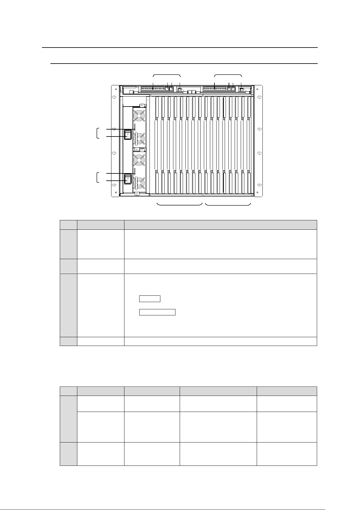
2. Panel Descriptions
No.
Name
Description
A
POWER1
Power switch 1 (standard equipment)
(1) Switch to turn unit power On/Off.
(2) DC power supply voltage indication LED
(Normal: lit green / Error: unlit)
B
POWER2 *1
Power switch 2 (optional equipment) (1) and (2) the same as
POWER1.
C
CPU1
CPU card (standard equipment/Primary CPU)
(1) Displays settings and alarms
(2) Alarm button to enter the ALARM menu. Effective during an alarm.
(ALARM button) (The LED lights red in an alarm.)
(3) Cancel button for menu settings.
(ACTIVE/BUS button) (The LED lights green when active)
(4) Used for menu operation (CONTROL knob)
* See section 4 “Settings via MFR-5000 Menus” for details on the menu
operation.
D
CPU2
CPU card (optional/Secondary CPU) (1) to (4) are the same as CPU1.
No.
Slot
Video Card
Audio Card
16DTIO Card
E
INPUT 1 - 4
(No. 01 - 04)
16SDI/16SDIA
Max. 4 cards
16AESI: Max. 4 cards
No. 01, 03
Max. 2 cards
INPUT 5 - 8
(No. 05 - 08)
16SDI/16SDIA
Max. 4 cards
16ADI: Max. 4 cards
16AAI: Max. 4 cards
16AAIEX: Max. 4 cards
16AESI: Max. 4 cards
No. 05, 07
Max. 2 cards
F
OUTPUT 1 - 8
(No. 09 - 16)
16SDO
Max. 8 cards.
16ADAO: Max. 8 cards
16AAOEX: Max. 4 cards
16AESO: Max. 8 cards
No. 09, 11, 13, 15
Max. 4 cards
1234567
8
1234567
8
123456781234567
8
16 15 14 13 12 11 10 09 08 07 06 05 04 03 02 01 ← Slot No
C
E
F
(1)
(2)
(3)
(4) D (1)
(2)
(3)
(4) A (1)
(2)
B
(1)
(2)
2-1. MFR-5000 Front Panel
*1 When installing the second power supply unit, be sure to set PS2 INSTALL to
INSTALLED under SETTING > MU SETTING > PS2 INSTALL in the CPU card front
menu. (See section 4. “Settings via MFR-5000 Menus”)
Input / Output Card Slots
15
Page 16
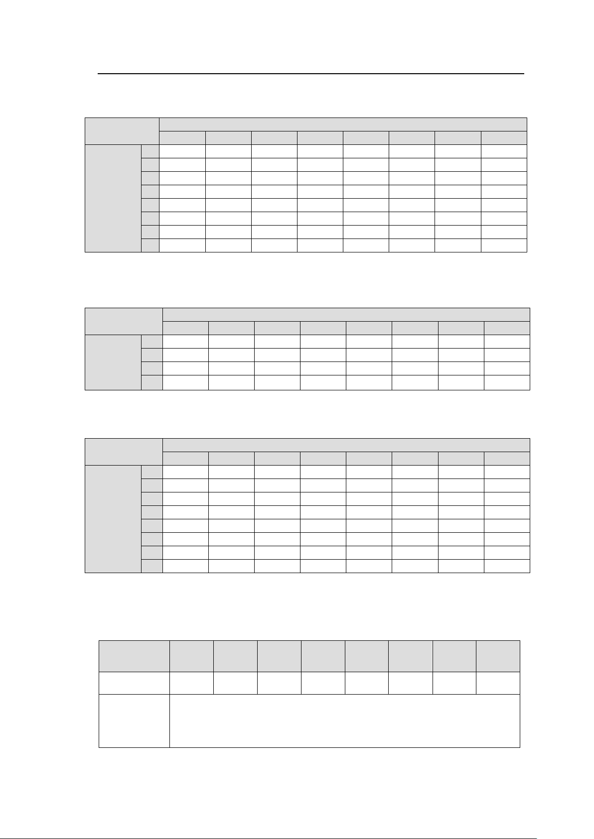
2-1-1. Matrix Size Chart
Number of cards: MFR-16SDO
8 7 6 5 4 3 2
1
Number of
cards:
MFR-16SDI/
16SDIA
8
128 x 128
128 x 112
128 x 96
128 x 80
128 x 64
128 x 48
128 x 32
128 x 16
7
112 x 128
112 x 112
112 x 96
112 x 80
112 x 64
112 x 48
112 x 32
112 x 16
6
96 x 128
96 x 112
96 x 96
96 x 80
96 x 64
96 x 48
96 x 32
96 x 16
5
80 x 128
80 x 112
80 x 96
80 x 80
80 x 64
80 x 48
80 x 32
80 x 16
4
64 x 128
64 x 112
64 x 96
64 x 80
64 x 64
64 x 48
64 x 32
64 x 16
3
48 x 128
48 x 112
48 x 96
48 x 80
48 x 64
48 x 48
48 x 32
48 x 16
2
32 x 128
32 x 112
32 x 96
32 x 80
32 x 64
32 x 48
32 x 32
32 x 16
1
16 x 128
16 x 112
16 x 96
16 x 80
16 x 64
16 x 48
16 x 32
16 x 16
Number of cards: MFR-16ADAO
8 7 6 5 4 3 2
1
Number of
cards:
MFR-16ADI
or
16AAI
4
64 x 64
64 x 56
64 x 48
64 x 40
64 x 32
64 x 24
64 x 16
64 x 8
3
48 x 64
48 x 56
48 x 48
48 x 40
48 x 32
48 x 24
48 x 16
48 x 8
2
32 x 64
32 x 56
32 x 48
32 x 40
32 x 32
32 x 24
32 x 16
32 x 8
1
16 x 64
16 x 56
16 x 48
16 x 40
16 x 32
16 x 24
16 x 16
16 x 8
Number of cards: MFR-16AESO or 16AAOEX
8 7 6 5 4 3 2
1
Number of
cards:
MFR-
16AESI
or
16AAIEX
8
128 x 128
128 x 112
128 x 96
128 x 80
128 x 64
128 x 48
128 x 32
128 x 16
7
112 x 128
112 x 112
112 x 96
112 x 80
112 x 64
112 x 48
112 x 32
112 x 16
6
96 x 128
96 x 112
96 x 96
96 x 80
96 x 64
96 x 48
96 x 32
96 x 16
5
80 x 128
80 x 112
80 x 96
80 x 80
80 x 64
80 x 48
80 x 32
80 x 16
4
64 x 128
64 x 112
64 x 96
64 x 80
64 x 64
64 x 48
64 x 32
64 x 16
3
48 x 128
48 x 112
48 x 96
48 x 80
48 x 64
48 x 48
48 x 32
48 x 16
2
32 x 128
32 x 112
32 x 96
32 x 80
32 x 64
32 x 48
32 x 32
32 x 16
1
16 x 128
16 x 112
16 x 96
16 x 80
16 x 64
16 x 48
16 x 32
16 x 16
Number of
MFR-16DTIO
cards
8 7 6 5 4 3 2 1 Number of
RS-422 ports
128
112
96
80
64
48
32
16
Routing
Matrix size can be freely selected depending on the number of installed MFR-16DTIO
cards, regardless of their slot location.
RS-422 data can be routed between ports in the same card or different cards.
See section 2-5. “RS-422 Data Input / Output Cards” for details on input and output port
settings.
Standard SDI Signal Routing
Matrix size varies depending on the number of installed MFR-16SDI/16SDIA and
MFR-16SDO cards as shown below. (128 x 128 to 16 x 16)
AUDIO Signal Routing
Matrix size varies depending on the number of installed MFR-16ADI, MFR-16AAI and
MFR-16ADAO cards as shown below. (1 stereo pair = 2 channels)
Matrix size varies depending on the number of installed MFR-16AESI, MFR-16AESO,
MFR-16AAIEX and MFR-16AAOEX cards as shown below. (1 stereo pair = 2 channels)
* Up to 4 cards for MFR-16AAIEX and MFR-16AAOEX cards
► See section 2-4. "Audio Input / Output Cards" for details on audio input and output cards.
RS-422 Data Routing
Matrix size can be freely selected depending on the number of installed MFR-16DTIO cards,
regardless of their slot location, as shown below.
16
Page 17
2-1-2. Input / Output Card Installation and Removal
POWER 2
MFR -50 00
POWER 1
ON
OFF
ON
OFF
ACTIVE
CPU 1
ALARM ALARM ACTIVE
CPU 2
MESSAGE/ME NUMESSAGE/ME NU
ROUTING SWITCHER
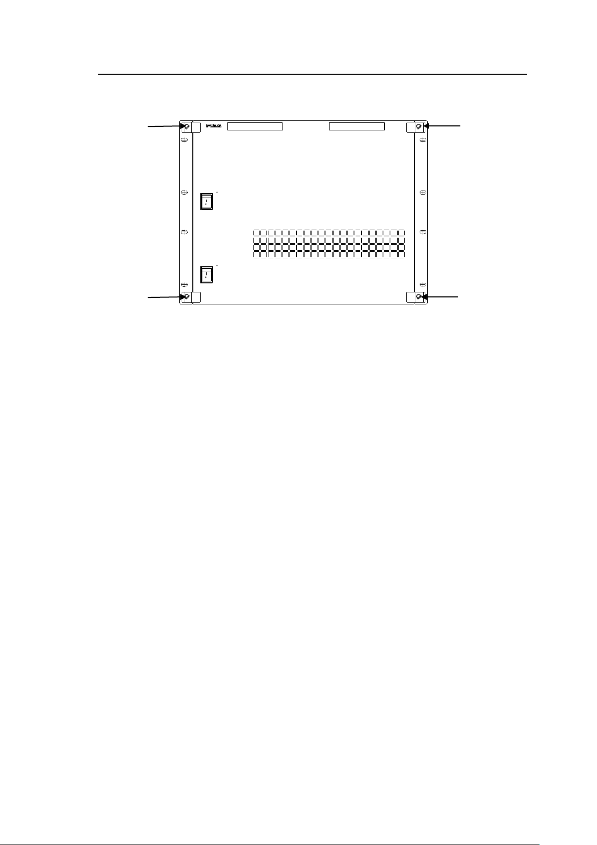
MFR input/output cards should be installed by opening the MFR-5000 front panel. Remove
the four screws on the front panel as shown below to open the front panel.
Removing an MFR Input/Output card
To remove an input or output card with the MFR-5000 powered on, turn the power of the
slot from which to remove the card OFF. Be sure to turn the power of the slot off before
removing its card.
►See [SHUTDOWN] in section 4-5. “SETTINGS.”
Installing an MFR Input/Output card
To install an MFR option card with the MFR-5000 powered on, turn the power of the slot
on, using the front menu, after installing the card.
► See [SHUTDOWN] in section 4-5. “SETTINGS.”
MFR cards must be installed into their respective designated slots from the correct side.
►See section 2-1. “MFR-5000 Front Panel.”
17
Page 18
2-1-3. CPU Card Installation and Removal
IMPORTANT
Do not touch any other parts on the card. Static electricity may damage sensitive
electrical components on the card.
Front
S2
8 7 6 5 4 3 2
1
OFF
ON
S1
422
422
232C
232C
S4
S3
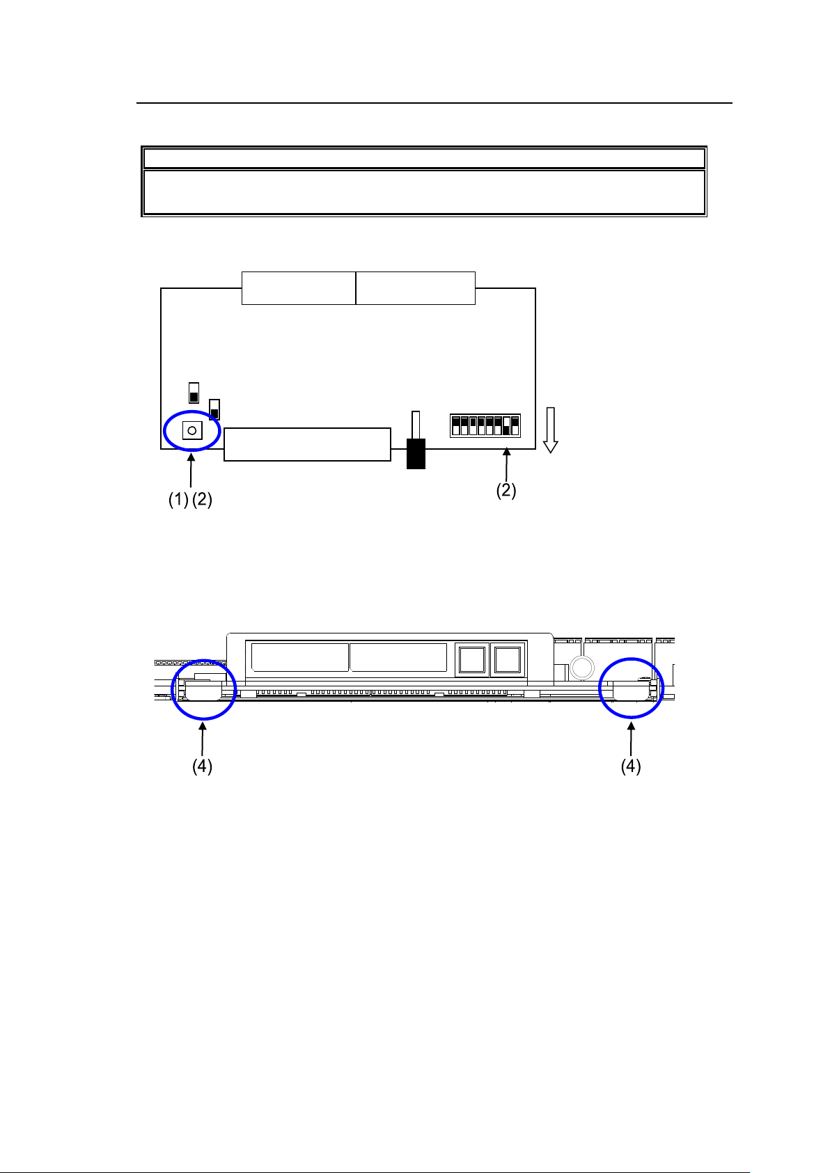
CPU cards can be installed or removed with the MFR-5000 power turned on as shown below.
Removing a CPU card
(1) Press the reset button (S1) on the CPU card.
(2) Repress and hold the button, then turn ON the switch 2 of Dipswitch S2.
(3) Release the button. The menu display will turn off automatically.
(4) Hold the two black handles at both sides on the CPU card and gradually remove the card
from the chassis.
18
Page 19
Inserting a CPU card
Front
S2 8 7 6 5 4 3 2 1
OFF
ON
S1
422
422
232C
232C
S4
S3
ACTIVE/BUSY button
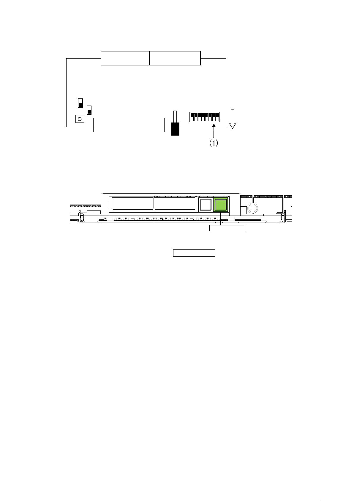
(1) Verify that the switch 2 of Dipswitch S2 on the card is turned OFF.
If not, turn the switch to OFF.
(2) If the installed CPU card is not active (ACTIVE/BUSY lights green.), wait for 20 seconds.
(3) Align a new CPU card with the slot guide rails and insert the card into the slot.
(4) Verify that the card is firmly installed.
19
Page 20
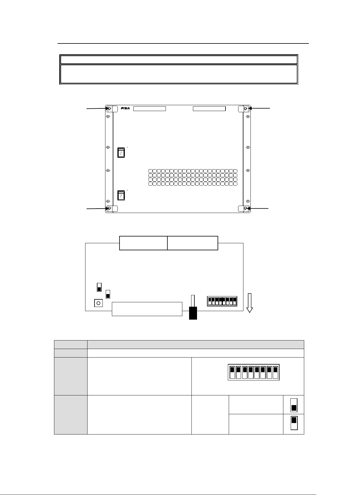
2-1-4. CPU Card Switch Settings
IMPORTANT
Note that internal switch settings should only be performed by qualified technical
personnel.
Switch
Settings
S1
Reset switch for the CPU card.
S2
For maintenance use. Do not change
these settings except when removing
the CPU card. (Factory default
settings are as shown in the right
figure. The black squares (■) depict
the switch positions.)
S3, S4
Used to select RS-232C or RS-422.
Make your selection referring to the
right figures. Both switches must be
set the same.
CPU1 and CPU2 must use the same
settings.
Switch
settings
RS-232C
(Factory default)
RS-422
Front
S2 8 7 6 5 4 3 2 1
OFF
ON
S1
422
422
232C
232C
S4
S3
OFF
ON
POWER 2
MFR -50 00
POWER 1
ON
OFF
ON
OFF
ACTIVE
CPU 1
ALARM ALARM ACTIVE
CPU 2
MESSAGE/ME NUMESSAGE/ME NU
ROUTING SWITCHER
(1) Remove the 4 screws on the MFR-5000 front panel to remove the panel.
(2) The CPU card factory default settings are as shown below.
Switch settings
► See section 2-1-3. “CPU Card Installation and Removal” to remove a CPU card.
20
Page 21
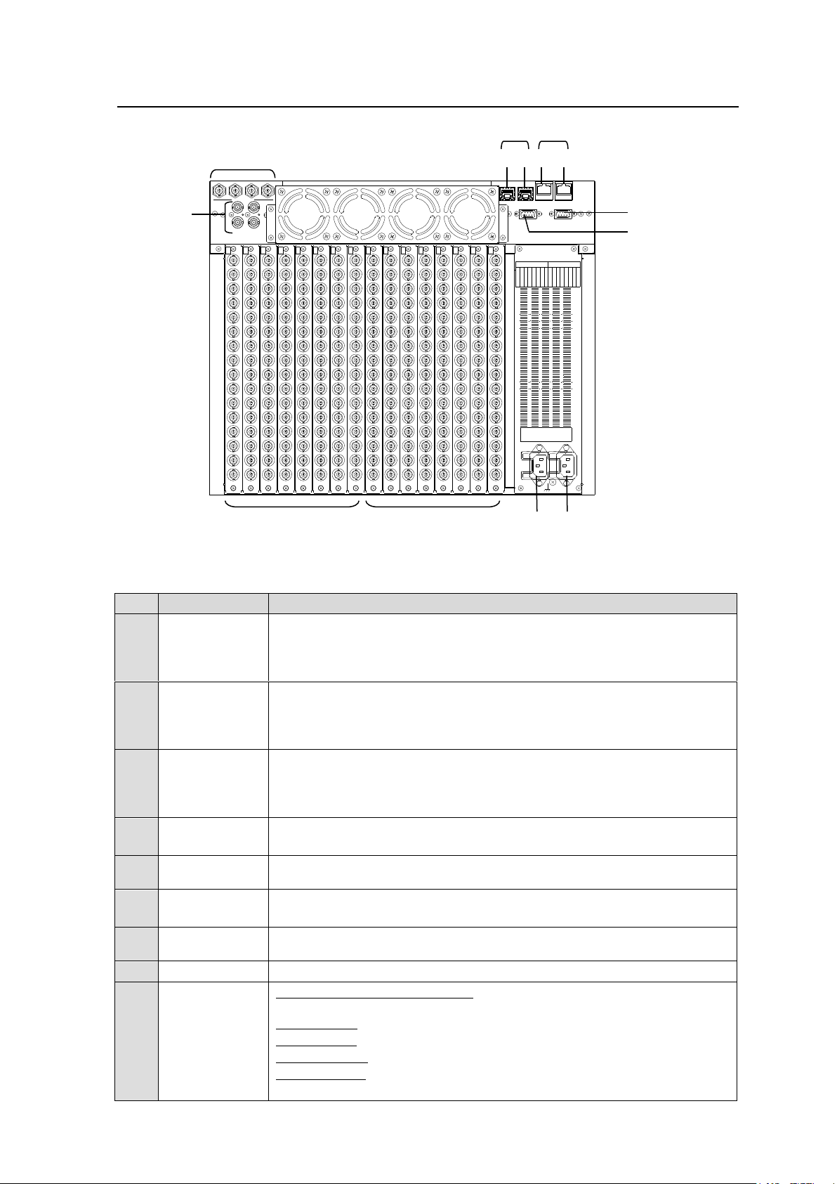
2-2. MFR-5000 Rear Panel
No.
Name
Description
A
MFR-LAN *1
Ethernet ports for connection to MFR Remote Control Units and MFR-GPI
(10/100/1000BASE-T, RJ-45)
(1) For CPU 1
(2) For CPU 2
B
PC-LAN *1
Ethernet ports for connection to PC or other external unit
(10/100BASE-TX RJ-45)
(1) For CPU 1
(2) For CPU 2
C
SERIAL *2
Used for control via a serial interface. RS-232C or RS-422 selectable.
► See section 2-2-1. "Interfaces."
The SERIAL connector is set to RS-232C as factory default. Consult your
FOR-A reseller if you wish to change the setting.
D
ALARM
Used for alarm output
► See section 2-2-1. "Interfaces."
E
MONITOR
OUTPUT 1 - 4
Used for monitor outputs (No automatic reclocking)
F
REF IN1, 2
Used to input reference signals (BB or Tri-level sync signal)
(with loop-through. Terminate with 75Ω terminator, if unused.)
G
AC IN1
Used to connect Power Supply Unit 1 (standard equipment) to an AC
power source
H
AC IN2
Used to connect Power Supply Unit 2 (optional) to an AC power source
I
INPUT
MFR-16SDI/16SDIA/16SDIGB: Used to input digital component video
signals
MFR-16ADI: Used to input digital audio signals
MFR-16AAI: Used to input analog audio signals
MFR-16AAIEX: Used to input analog audio signals
MFR-16AESI: Used to input digital audio signals
► See section 2-4. "Audio Input/Output Cards."
A
(1)
(2)
C
J
I F E G H
B
(2)
(1)
D
1 2 3 4
MONITOR OUT (SDI)
1 2
REF IN
SLOT
SERIALALARM
PC-LAN
(CPU2) (CPU1)(CPU2)(CPU1)
MFR-LAN
3G/HD/SD-SDI INPUT 3G/HD/SD-SDI OUTPUT
1 2 3 4 5 6 7 8 1 2 3 4 5 6 7 8
Rating Label
2
A
C
1
0
0
-
2
4
0
V
5
0
/
6
0
H
z
I
N
A
C
1
0
0
-
2
4
0
V
5
0
/
6
0
H
z
I
N
1
16
15
14
13
12
11
10
9
8
5
4
1
6
7
IN
1
3
2
16
15
14
13
12
11
10
9
8
5
4
1
6
7
IN
2
3
2
16
15
14
13
12
11
10
9
8
5
4
1
6
7
IN
3
3
2
16
15
14
13
12
11
10
9
8
5
4
1
6
7
IN
4
3
2
16
15
14
13
12
11
10
9
8
5
4
1
6
7
IN
5
3
2
16
15
14
13
12
11
10
9
8
5
4
1
6
7
IN
6
3
2
16
15
14
13
12
11
10
9
8
5
4
1
6
7
IN
7
3
2
16
15
14
13
12
11
10
9
8
5
4
1
6
7
IN
8
3
2
16
15
14
13
12
11
10
9
8
5
4
1
6
7
1
3
2
16
15
14
13
12
11
10
9
8
5
4
1
6
7
2
3
2
16
15
14
13
12
11
10
9
8
5
4
1
6
7
3
3
2
16
15
14
13
12
11
10
9
8
5
4
1
6
7
4
3
2
16
15
14
13
12
11
10
9
8
5
4
1
6
7
5
3
2
16
15
14
13
12
11
10
9
8
5
4
1
6
7
6
3
2
16
15
14
13
12
11
10
9
8
5
4
1
6
7
7
3
2
16
15
14
13
12
11
10
9
8
5
4
1
6
7
8
3
2
OUTOUTOUT
OUT
OUTOUT
OUT
OUT
* The above figure shows an MFR-5000 with MFR-16SDI/16SDIA and MFR-16SDO cards
installed.
21
Page 22
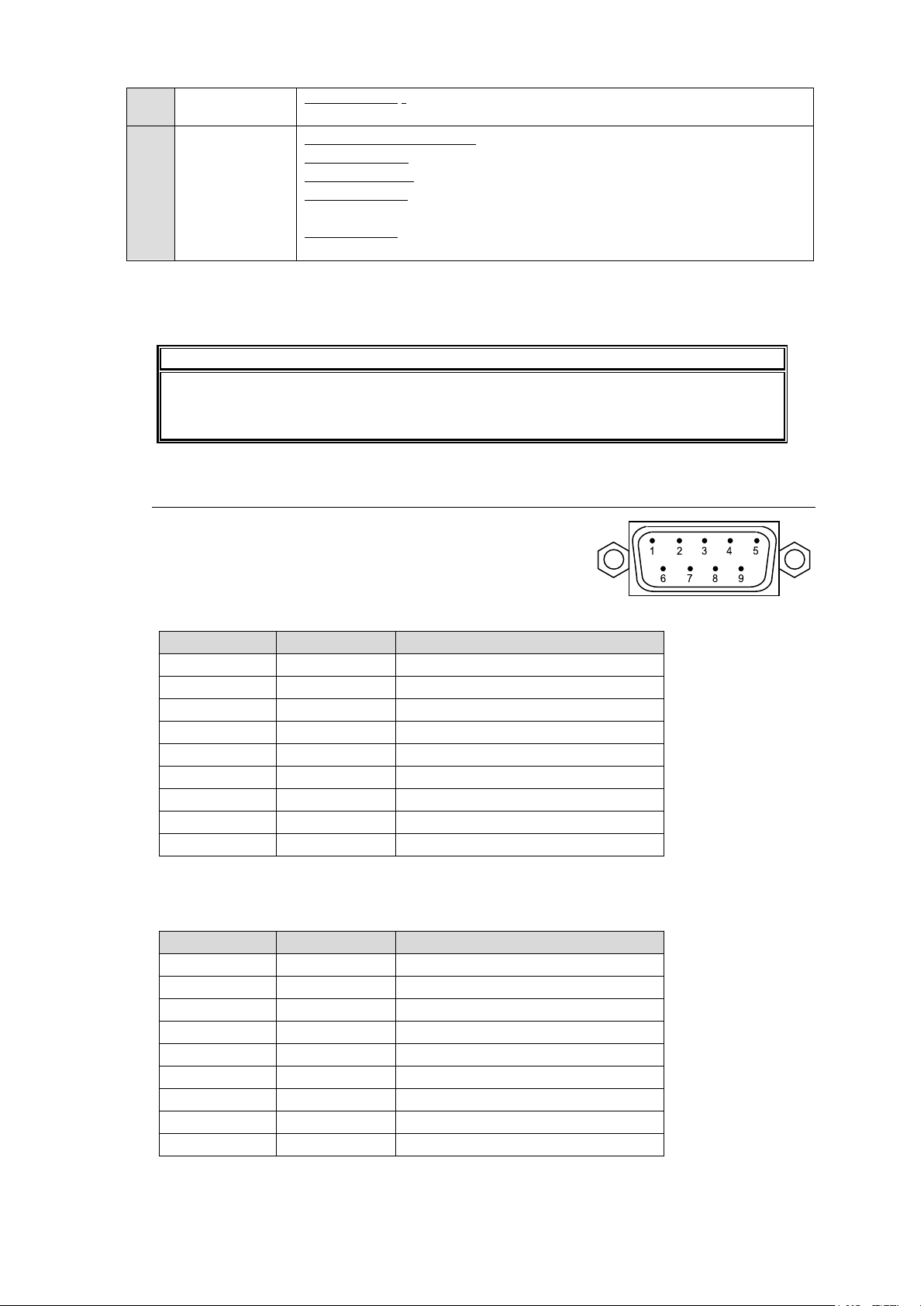
MFR-16DTIO: Used to input/output RS-422 data signals
► See section 2-5. "RS-422 Data Input/Output Cards."
J
OUTPUT
MFR-16SDO/16SDOGB: Used to output digital component video signals
MFR-16ADAO: Used to output digital/analog audio signals
MFR-16AAOEX: Used to output analog audio signals
MFR-16AESO Used to output digital audio signals
► See section 2-4. "Audio Input/Output Cards."
MFR-16DTIO: Used to input/output RS-422 data signals
► See section 2-5. " RS-422 Data Input/Output Cards."
*1 The MFR-LAN/MFR-LAN(CPU1, 2) connector may be labeled as TO RU, and the PC-LAN connector as TO
IMPORTANT
All 4 MFR-LAN and PC-LAN connectors (2 each) must be connected to their
respective devices to enable CPU redundancy. The LAN connections for MFR Series
devices must be separated from the network segment of other devices.
Pin No.
Signal Name
Description
1
NC
Not used 2 RxD
Received Data
3
TxD
Transmitted Data
4
DTR
Data Terminal Ready
5
SG
Signal Ground
6
DSR
Data Set Ready
7
RTS
Request To Send
8
CTS
Clear To Send
9
NC
Not used
Pin No.
Signal Name
Description
1
FG
Frame Ground
2
T-
Transmit data (-)
3
R+
Receive data (+)
4
SG
Signal Ground
5
NC
Unused 6 SG
Signal Ground
7
T+
Transmit data (+)
8
R-
Receive data (-)
9
FG
Frame Ground
PC on units shipped before Sep. 16, 2011.
*2 The SERIAL connector is set to RS-232C as factory default. Consult your FOR-A reseller if you wish to
change the setting.
2-2-1. Interfaces
SERIAL Connector (9-pin D-sub, male)
RS-232C or 422 interface can be selected
via the CPU card DIP switches.
RS-232C Connector Pin Assignments (Factory default settings)
* The maximum cable length is 10 m.
* DTR/DSR and RTS/CTS are internally connected respectively.
RS-422 connector pin assignment (9-pin, D-sub male)
* The maximum cable length is 100 m.
22
Page 23
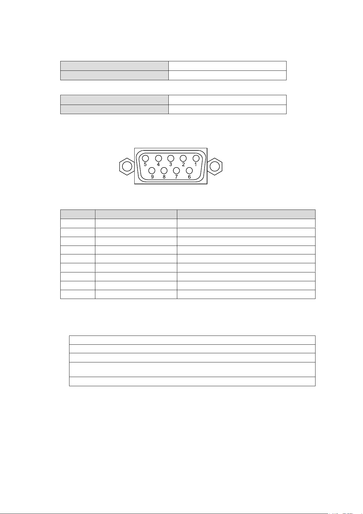
ALARM Connector (9-pin D-sub, female)
Under normal operation:
Pins 1 and 6 are open.
In a malfunction or power-off state:
Pins 1 and 6 are closed.
Under normal operation:
Pins 2 and 7 are open.
In a malfunction or power-off state:
Pins 2 and 7 are closed.
Pin No.
Signal Name
Description
1
ALARM 1 OUT
Alarm 1 output (Default setting: Fan)
2
ALARM 2 OUT
Alarm 2 output (Default setting: Power)
3
NC
Unused
4
NC
Unused
5
RESET IN
Reset in, active low
6
ALARM 1 COMMON
Alarm 1 output, common
7
ALARM 2 COMMON
Alarm 2 output, common
8
GND
Signal ground 9 GND
Signal ground
Fan (including power unit cooling fans)
Power
Secondary CPU error
CPU Changeover (issued when the secondary CPU is activated to change over the
operation)
Crosspoint Error
9-pin D-sub, female
Alarm 1 Out:
Alarm 2 Out:
Reset:
To reset the unit externally, short Pin 5 and a signal ground pin (8 or 9).
ALARM Connector Pin Assignments
The following items can be set for ALARM1 OUT and ALARM2 OUT. The alarms can be
assigned in the Web-Based Control.
Available alarm signals
23
Page 24
2-3. SDI Input/Output Cards
16
15
14
13
12
11
10
9
8
5
4
1
6
7
3
2
IN
1
16
15
14
13
12
11
10
9
8
5
4
1
6
7
3
2
1
OUT
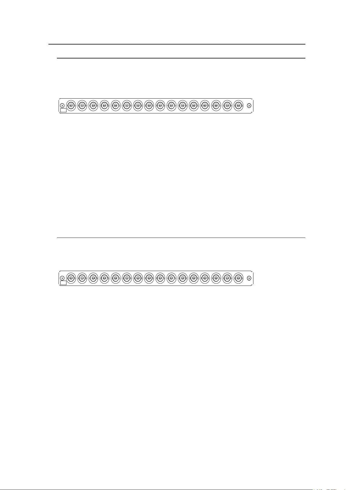
2-3-1. MFR-16SDI/16SDIA
MFR-16SDI/16SDIA is an SDI input card and can accept 16 of 3G/HD/SD-SDI and ASI
signals.
Up to 8 cards can be installed into Slot No. 01 to 08.
► See section 2-1-1. "Matrix Size Chart."
BNC x 16 inputs (3G/HD/SD-SDI or ASI signal auto-detection)
Set up input signals in the Web-based Control Software as shown below.
Source Name
In the left side of the Web-based Control screen, click to select [Router System Settings] [Source Name] in the menu tree to display the setting page.
This page allows you to change source names displayed on Remote Controllers or other
devices.
Source Assignment
Open the [Web-based Control: Router System Settings - Source Assignment page].
This page allows you to assign physical inputs to logical input channels.
2-3-2. MFR-16SDO
MFR-16SDO is an SDI output card and can output 16 of 3G/HD/SD-SDI and ASI signals.
Up to 8 cards can be installed into Slot No. 09 to 16.
► See section 2-1-1. "Matrix Size Chart."
BNC x 16 outputs (3G/HD/SD-SDI or ASI signal depending on crosspoint selections)
Set up output signals in the Web-based Control Software as shown below.
Destination Assignment
Open the [Web-based Control: Router System Settings - Destination Assignment page].
This page allows you to assign physical outputs to logical output channels.
Destination Name
Open the [Web-based Control: Router System Settings - Destination Name page].
This page allows you to change destination names displayed on Remote Controllers.
24
Page 25
2-3-3. MFR-16SDIGB
IN
1
1A
1B
1C
1D
2A
2B
2C
2D
12G / 3G-SDI12G / 3G-SDI
3A
3B
3D
3C
12G / 3G-SDI 12G / 3G-SDI
4A
4B
4C
4D
OUT
1
1A
1B
12G / 3G-SDI
1C
1D
2A
2B
2C
2D
12G / 3G-SDI
3A
3B
3C
3D
12G / 3G-SDI 12G / 3G-SDI
4A
4B
4C
4D
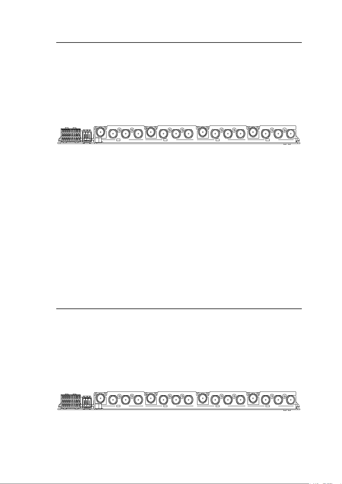
The MFR-16SDIGB is an SDI input card that accepts 12G- and 3G-SDI signals and supports
Gearbox feature in which video signal conversions between 12G-SDI and Quad Link 3G-SDI,
and between 2SI and SQD are available.
► See Sec. 8. "Gearbox Feature (MFR-16SDIGB/16SDOGB)."
The following numbers of inputs is available:
12G-SDI signal: Max 4 inputs (BNC: 1A, 2A, 3A and 4A)
3G-SDI signal: Max 16 inputs
Cards can be installed into Slot No. 01 to 08.
► See Sec. 2-1-1. "Matrix Size Chart."
BNC x 16 inputs (12G/3G-SDI)
Set up input signals in the Web-based Control Software as shown below.
Gearbox settings
In the left side of the Web-based Control screen, click to select [(Main Unit Settings) Gearbox Settings] in the menu tree to display the settings page.
This page allows you to specify input signals and conversion modes.
Source Assignment
In the left side of the Web-based Control screen, click to select [Router System Settings -
Source Assignment] in the menu tree to display the settings page.
This page allows you to assign physical inputs to logical input channels.
Source Name
In the left side of the Web-based Control screen, click to select [Router System Settings Source Name] in the menu tree to display the settings page.
This page allows you to change source names displayed on Remote Controllers or other
devices.
2-3-4. MFR-16SDOGB
The MFR-16SDOGB is an SDI output card that accepts 12G- and 3G-SDI signals and
supports Gearbox features in which video signal conversions between 12G-SDI and Quad
Link 3G-SDI, and between 2SI and SQD are available.
► See Sec. 8. "Gearbox Feature (MFR-16SDIGB/16SDOGB)."
The following numbers of outputs are available:
12G-SDI signal: Max 4 outputs (BNC: 1A, 2A, 3A and 4A)
3G-SDI signal: Max 16 outputs
Cards can be installed into Slot No. 09 to 16.
► See Sec. 2-1-1. "Matrix Size Chart."
BNC x 16 outputs (12G/3G-SDI)
25
Page 26
Set up output signals in the Web-based Control Software as shown below.
IMPORTANT
When using an MFR-16AAI, a Black Burst signal should be input to REF IN2.
MFR-16AAOEX
MFR-16ADAO
MFR-16AESO
MFR-16AAI
- ✓ -
MFR-16AAIEX
✓ - ✓
Analog Input Terminal
Select 600 ohm or High impedance for analog input.
Analog Input Level
Adjust analog input level.
(No.)
AAI
ANALOG AUDIO
IN
1 - 8 9 - 16 17 - 24
25 - 32
Gearbox settings
In the left side of the Web-based Control screen, click to select [(Main Unit Settings) Gearbox Settings] in the menu tree to display the settings page.
This page allows you to specify output signals and conversion modes.
Destination Assignment
Open the [Web-based Control: Router System Settings - Destination Assignment page].
This page allows you to assign physical outputs to logical output channels.
Destination Name
Open the [Web-based Control: Router System Settings - Destination Name page].
This page allows you to change destination names displayed on Remote Controllers.
2-4. Audio Input / Output Cards
Source and destination assignment procedures for audio signals are the same as those for SDI
signals. Refer to the previous chapter This chapter describes audio specific setup. Audio signals
should be setup in the Web-based Control pages
► See [Web-based Control: Audio Settings page].
2-4-1. MFR-16AAI / 16AAIEX (Analog Input)
MFR-16AAI/16AAIEX is an analog audio input card with A/D converter.
Up to 4 cards can be installed into Slot No. 05 to 08.
► See section 2-1-1. "Matrix Size Chart."
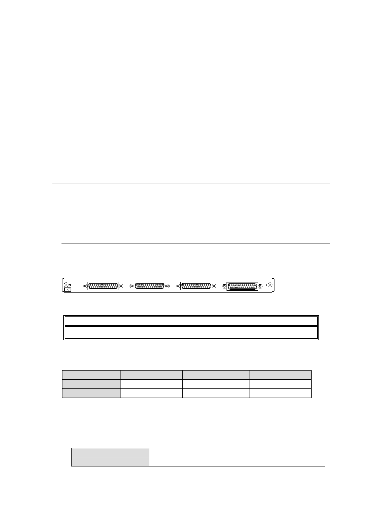
25-pin D-sub (female) x 4 (16 stereo pairs, 32 channels), 600 Ohm or high impedance
To output analog audio signals input to MFR-16AAI and MFR-16AAIEX, a compatible analog
audio output card should be installed into the MFR main unit.
✓: Compatible, -: Incompatible
Analog Audio Input
Select the input impedance and adjust the input level per each stereo pair (2 channels) in the
[Web-based Control: Audio Settings page].
26
Page 27
Pin No.
Setting
Pin No.
Setting
13
CH1+
25
CH1 COM
12
CH1-
24
CH2+
11
CH2 COM
23
CH2-
10
CH3+
22
CH3 COM
9
CH3-
21
CH4+
8
CH4 COM
20
CH4-
7
CH5+
19
CH5 COM
6
CH5-
18
CH6+
5
CH6 COM
17
CH6-
4
CH7+
16
CH7 COM
3
CH7-
15
CH8+
2
CH8 COM
14
CH8-
1
SG - -
Pin No.
Setting
Pin No.
Setting
13
CH9+
25
CH9 COM
12
CH9-
24
CH10+
11
CH10 COM
23
CH10-
10
CH11+
22
CH11 COM
9
CH11-
21
CH12+
8
CH12 COM
20
CH12-
7
CH13+
19
CH13 COM
6
CH13-
18
CH14+
5
CH14 COM
17
CH14-
4
CH15+
16
CH15 COM
3
CH15-
15
CH16+
2
CH16 COM
14
CH16-
1
SG
-
-
Pin No.
Setting
Pin No.
Setting
13
CH17+
25
CH17 COM
12
CH17-
24
CH18+
11
CH18 COM
23
CH18-
10
CH19+
22
CH19 COM
9
CH19-
21
CH20+
8
CH20 COM
20
CH20-
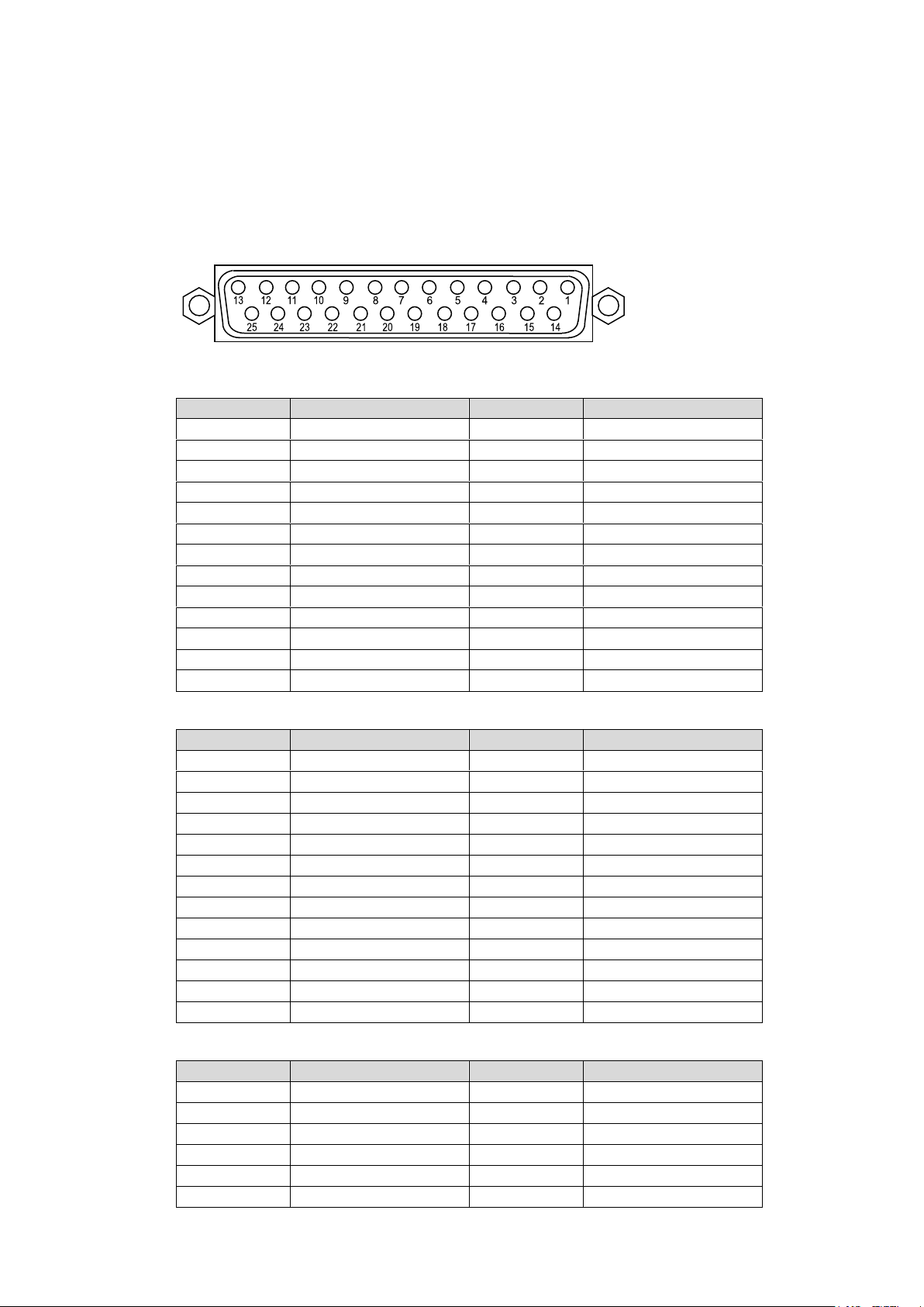
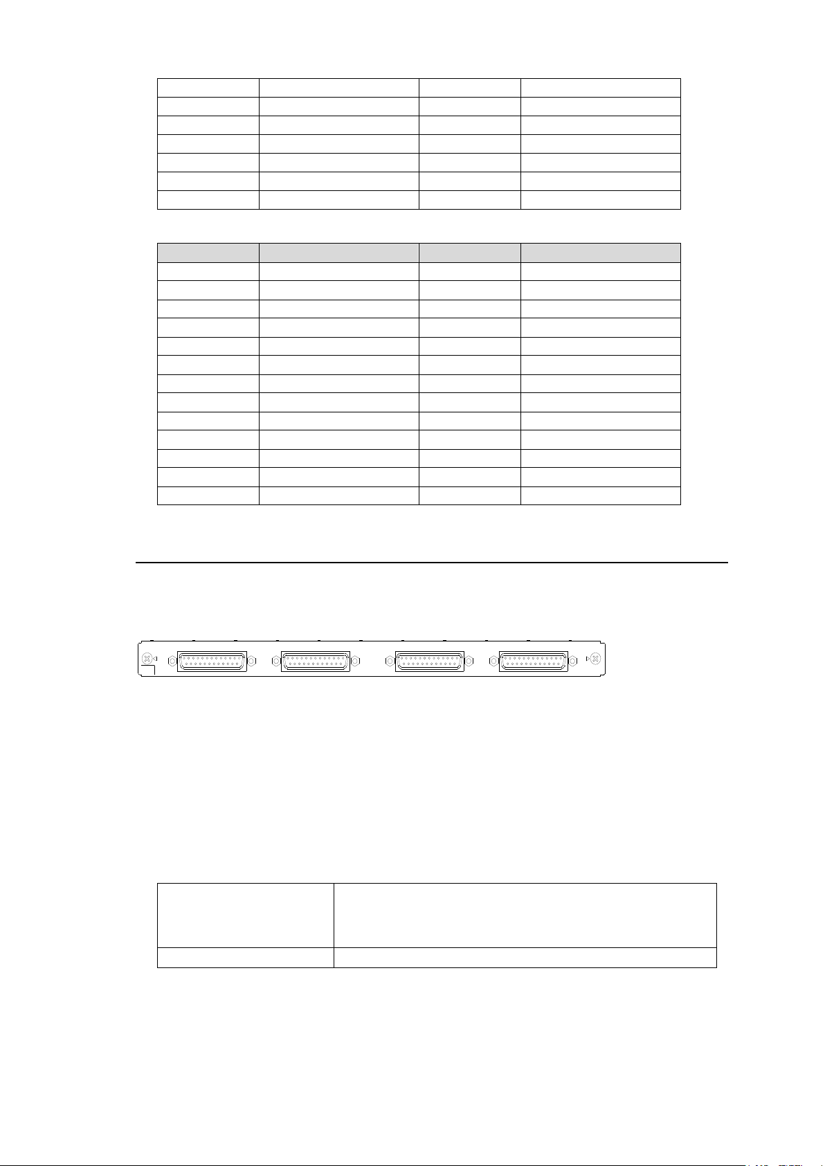
Analog Audio Connection
For balanced audio signals, connect the hot, cold and shield conductor to "+" ," - " and
"COM" pins respectively.
For unbalanced audio signals, connect the conductor that carries audio to a "+" pin and
ground to "COM."
Analog Audio Connector (25-pin D-sub, female, inch screws) x 4
Connector Pin Assignments
Channels 1 to 8
Channels 9 to 16
Channels 17 to 24
27
Page 28
7
CH21+
19
CH21 COM
6
CH21-
18
CH22+
5
CH22 COM
17
CH22-
4
CH23+
16
CH23 COM
3
CH23-
15
CH24+
2
CH24 COM
14
CH24-
1
SG - -
Pin No.
Setting
Pin No.
Setting
13
CH25+
25
CH25 COM
12
CH25-
24
CH26+
11
CH26 COM
23
CH26-
10
CH27+
22
CH27 COM
9
CH27-
21
CH28+
8
CH28 COM
20
CH28-
7
CH29+
19
CH29 COM
6
CH29-
18
CH30+
5
CH30 COM
17
CH30-
4
CH31+
16
CH31 COM
3
CH31-
15
CH32+
2
CH32 COM
14
CH32-
1
SG - -
A
N
A
L
O
G
A
U
D
I
O
1~8
9~16 17~24
25~32
Level
Sets analog output level for each stereo pair.
Audio output level is determined by the digital input level and
this setting as shown in the table on next page. Maximum
output level is +24 dBm.
Gain
Adjusts analog output level for each channel.
Channels 25 to 32
2-4-2. MFR-16AAOEX (Analog Output)
MFR-16AAOEX is an analog audio output card with D/A converter.
Up to 4 cards can be installed into Slot No. 09 to 16.
► See section 2-1-1. "Matrix Size Chart."
MUTE
Mute can be enabled or disabled for each stereo pair (2 channels).
Mute should be set in the [Web-based Control: Audio Settings page].
Digital-to-Analog Conversion
32 channels (16 stereo pairs) can be converted and output as analog audio. Audio level and
gain can be set for each stereo pair.
Audio level and gain should be set in the [Web-based Control: Audio Settings page].
28
Page 29
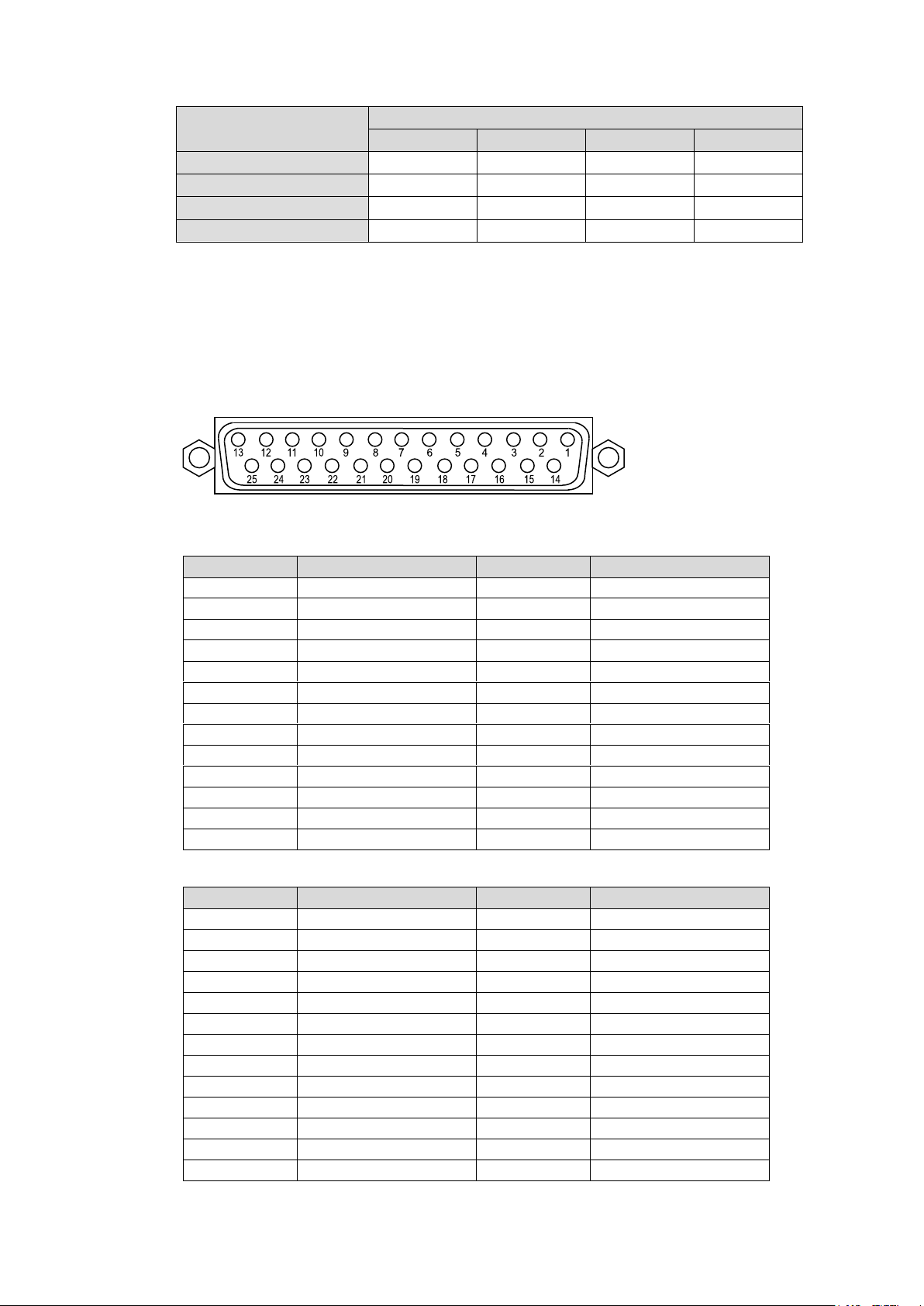
Analog Output Level (determined by the input level and level setting)
Digital audio input level
Analog Output Level Setting
-10dBm
0dBm
4dBm
8dBm
-24dBFS
-14dBm
-4dBm
0dBm
+4dBm
-20dBFS
-10dBm
0dBm
+4dBm
+8dBm
-18dBFS
-8dBm
+2dBm
+6dBm
+10dBm
0dBFS
+10dBm
+20dBm
+24dBm
CLIP
Pin No.
Setting
Pin No.
Setting
13
CH1 +
25
CH1 COM
12
CH1 -
24
CH2 +
11
CH2 COM
23
CH2 -
10
CH3 +
22
CH3 COM
9
CH3 -
21
CH4 +
8
CH4 COM
20
CH4 -
7
CH5 +
19
CH5 COM
6
CH5 -
18
CH6 +
5
CH6 COM
17
CH6 -
4
CH7 +
16
CH7 COM
3
CH7 -
15
CH8 +
2
CH8 COM
14
CH8 -
1
SG - -
Pin No.
Setting
Pin No.
Setting
13
CH9 +
25
CH9 COM
12
CH9 -
24
CH10 +
11
CH10 COM
23
CH10 -
10
CH11 +
22
CH11 COM
9
CH11 -
21
CH12 +
8
CH12 COM
20
CH12 -
7
CH13 +
19
CH13 COM
6
CH13 -
18
CH14 +
5
CH14 COM
17
CH14 -
4
CH15 +
16
CH15 COM
3
CH15 -
15
CH16 +
2
CH16 COM
14
CH16 -
1
SG - -
Analog Audio Connection
For balanced audio signals, connect the hot, cold and shield conductor to "+" ," - " and
"COM" pins respectively.
For unbalanced audio signals, connect the conductor that carries audio to a "+" pin and
ground to "COM."
Analog Audio Connector (25-pin D-sub, female, inch screws) x 2
Connector Pin Assignments
Channels 1 to 8
Channels 9 to 16
29
Page 30
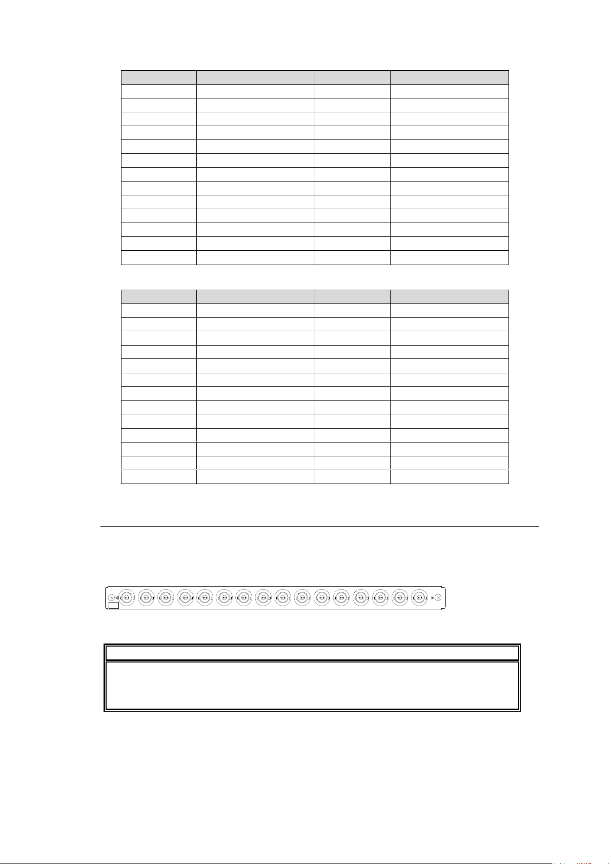
Channels 17 to 24
Pin No.
Setting
Pin No.
Setting
13
CH17 +
25
CH17 COM
12
CH17 -
24
CH18 +
11
CH18 COM
23
CH18 -
10
CH19 +
22
CH19 COM
9
CH19 -
21
CH20 +
8
CH20 COM
20
CH20 -
7
CH21 +
19
CH21 COM
6
CH21 -
18
CH22 +
5
CH22 COM
17
CH22 -
4
CH23 +
16
CH23 COM
3
CH23 -
15
CH24 +
2
CH24 COM
14
CH24 -
1
SG - -
Pin No.
Setting
Pin No.
Setting
13
CH25 +
25
CH25 COM
12
CH25 -
24
CH26 +
11
CH26 COM
23
CH26 -
10
CH27 +
22
CH27 COM
9
CH27 -
21
CH28 +
8
CH28 COM
20
CH28 -
7
CH29 +
19
CH29 COM
6
CH29 -
18
CH30 +
5
CH30 COM
17
CH30 -
4
CH31 +
16
CH31 COM
3
CH31 -
15
CH32 +
2
CH32 COM
14
CH32 -
1
SG - -
IMPORTANT
When using an MFR-16ADI, a Black Burst signal should be input to REF IN2.
To output the MFR-16ADI digital audio input, use MFR-16ADAO. The
MFR-16AESO/16AAOEX cannot output MFR-16ADI audio channels.
19/20
21/22
29/30
27/28
25/26
23/24
17/18
15/16
13/14
11/12
9/10
7/8
5/6
3/4
31/32
1/2
ADI
(No.)
Channels 25 to 32
2-4-3. MFR-16ADI (AES Input with SRC)
MFR-16ADI is an AES/EBU audio input card with SRC.
Up to 4 cards can be installed into Slot No. 05 to 08.
► See section 2-1-1. "Matrix Size Chart."
BNC x 16 inputs (16 stereo pairs, 32 channels), unbalanced, 75 Ohm
SRC (Sample Rate Converter)
A Sample Rate Converter is implemented in MFR-16ADI cards.
It allows you to accept audio signals of the following frequencies:
32 kHz, 44.1 kHz, 48 kHz and 96 kHz
30
Page 31
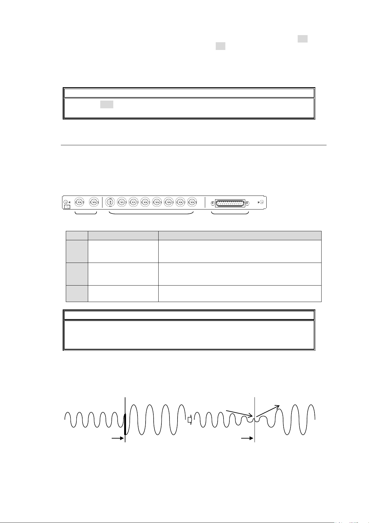
If an audio input stereo pair meets the following conditions, set these channels to ON in the
IMPORTANT
If setting to OFF for asynchronous or other frequency audio channels, their output will
be noisy or choppy.
No.
Name
Description
1
SDI OUT1
SDI OUT2
Outputs SDI audio embedded SDI signals (8 stereo pairs,
16 channels), BNC x 2
* Supported video formats: 1080/59.94i and 1080/60i
2
DIGITAL AUDIO OUT
1/2 to 15/16
Outputs AES/EBU signals (8 stereo pairs, 16 channels),
unbalanced, 75-ohm, BNC x 8
* Output audio is synchronized with the REF IN2 input.
3
ANALOG AUDIO OUT
1 to 8
Outputs analog audio signals (4 stereo pairs, 8 channels)
balanced or unbalanced, 25-pin D-Sub x 1 (female),
IMPORTANT
When MFR-16ADAO cards are installed, Black Burst signal should be input to REF
IN2.
MFR-16ADAO cards can output audio signals input to MFR-16ADI or MFR-16AAI.
2 1 3
SDI OUT
7/8
3/4
1
1/2
5/6
15/16
13/14
11/12
9/10
2
OUT
OUT
(No.)
1 ~ 8
ANALOG AUDIO
ADAO
DIGITAL AUDIO
Crosspoint switching
Crosspoint switching
Fade-in
Fade-out
[Web-based Control: Audio Settings page]. If set to ON, the channels are synchronized to
the external reference input and resampled to 48 kHz.
Audio signals of other frequencies than 48kHz
Audio signals asynchronous to the external reference input
2-4-4. MFR-16ADAO (Embedded / AES / Analog Output)
MFR-16ADAO is an audio output card with D/A converter. Each card can output the same
audio (up to 8 stereo pairs, 16 channels) from 2 SDI, 8 AES/EBU and analog (4 stereo pairs)
output connectors.
Up to 8 cards can be installed into Slot No. 09 to 16.
► See section 2-1-1. "Matrix Size Chart."
V-Fade
The V-Fade function can erase switching noise by setting fade-in and fade-out duration time.
V-Fade should be set in the [Web-based Control: Audio Settings page].
31
Page 32
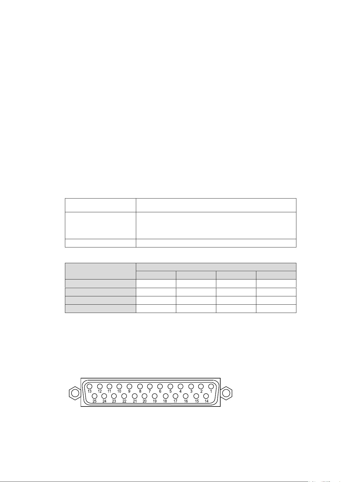
Select AES
Selects 4 stereo pairs (8 channels) output as analog audio
from the AES/EBU output channels.
Level
Sets analog signal output level for each channel.
Audio output level is determined by the digital input level and
this setting as shown in the table below. Maximum output
level is +24dBm.
Gain
Adjusts signal gain for each channel.
Digital audio input level
Analog Output Level Setting
-10dBm
0dBm
4dBm
8dBm
-24dBFS
-14dBm
-4dBm
0dBm
+4dBm
-20dBFS
-10dBm
0dBm
+4dBm
+8dBm
-18dBFS
-8dBm
+2dBm
+6dBm
+10dBm
0dBFS
+10dBm
+20dBm
+24dBm
CLIP
Audio De-embedding from SDI
In addition to audio channels input to MFR-16ADI, embedded audio channels input to
MFR-16SDI/16SDIA can output from MFR-16ADAO by de-embedding audio from SDI
signals.
SDI-embedded audio should be set in the [Web-based Control: Audio Settings page].
Note that embedded audio should meet the following requirements. Otherwise, audio
output should be choppy or noisy.
- Audio signals at 48kHz sample rates.
- HD-SDI embedded audio signals that are synchronized to the external reference signal
(REF IN2 input). 3G and SD SDI embedded audio signals are not properly synchronized.
MUTE
Mute can be enabled or disabled for stereo pair (2 channels).
Mute should be set in the [Web-based Control: Audio Settings page].
Digital-to-Analog Conversion
8 channels (4 stereo pairs) can be converted and output as analog audio. Audio level and
gain can be set for each stereo pair.
Audio level and gain should be set in the [Web-based Control: Audio Settings page].
Analog Output Level (determined by the input level and level setting)
Analog Audio Connection
For balanced audio signals, connect the hot, cold and shield conductor to "+" ," - " and
"COM" pins respectively.
For unbalanced audio signals, connect the conductor that carries audio to a "+" pin and
ground to "COM."
Analog Audio Connector (25-pin D-sub, female, inch screws)
32
Page 33
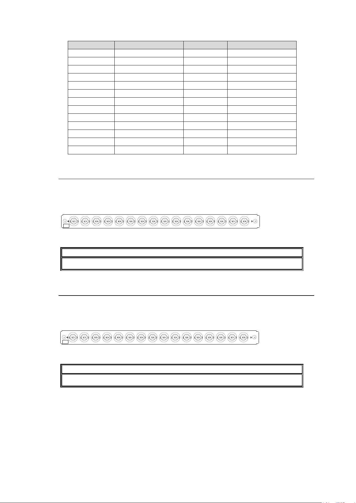
Pin Assignments
Pin No.
Setting
Pin No.
Setting
13
CH1 OUT+
25
CH1 OUT COM
12
CH1 OUT-
24
CH2 OUT+
11
CH2 OUT COM
23
CH2 OUT-
10
CH3 OUT+
22
CH3 OUT COM
9
CH3 OUT-
21
CH4 OUT+
8
CH4 OUT COM
20
CH4 OUT-
7
CH5 OUT+
19
CH5 OUT COM
6
CH5 OUT-
18
CH6 OUT+
5
CH6 OUT COM
17
CH6 OUT-
4
CH7 OUT+
16
CH7 OUT COM
3
CH7 OUT-
15
CH8 OUT+
2
CH8 OUT COM
14
CH8 OUT-
1
SG - -
IMPORTANT
To output MFR-16AESI input audio, MFR-16AESO/16AAOEX is required.
IMPORTANT
MFR-16AESO cards can output audio signals input to MFR-16AESI/16AAIEX.
19/20
21/22
29/30
27/28
25/26
23/24
17/18
15/16
13/14
11/12
9/10
7/8
5/6
3/4
31/32
1/2
ADI
(No.)
19/20
21/22
29/30
27/28
25/26
23/24
17/18
15/16
13/14
11/12
9/10
7/8
5/6
3/4
31/32
1/2
ADI
(No.)
2-4-5. MFR-16AESI (AES Input)
MFR-16AESI is a digital audio input card.
Up to 8 cards can be installed into Slot No. 01 to 08.
► See section 2-1-1. "Matrix Size Chart."
BNC x 16 inputs (16 stereo pairs, 32 channels), unbalanced, 75 Ohm
2-4-6. MFR-16AESO (AES Output)
MFR-16AESO is a digital audio output card.
Up to 8 cards can be installed into Slot No. 09 to 16.
► See section 2-1-1. "Matrix Size Chart."
BNC x 16 outputs (16 stereo pairs, 32 channels), unbalanced, 75 Ohm
33
Page 34
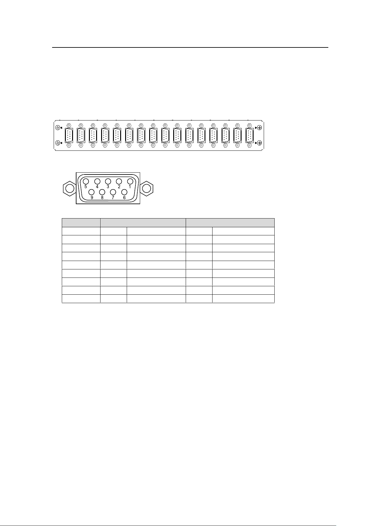
2-5. RS-422 Data Input / Output Cards
1
2
3
4
5
6
7
8
9
10
11
12
13
14
15
16
Pin no.
Device type *
Controller type *
1
GND
GND
2
TX--
Transmit data(-)
RX-
Receive data(-)
3
RX+
Receive data(+)
TX+
Transmit data(+)
4
GND
GND
5
NC NC
6
GND
GND
7
TX+
Transmit data(+)
RX+
Receive data(+)
8
RX-
Receive data(-)
TX-
Transmit data(-)
9
GND
GND
MFR-16DTIO is an RS-422 serial control input/output card compliant with the SMPTE 207M
standard. .
Up to 8 cards can be installed into the following slots:
No. 01, 03, 05, 07, 09, 11, 13, 15
► See section 2-1-1. "Matrix Size Chart."
MFR-16DTIO Card
RS-422 Connector: 9-pin D-sub (female) x 16
Connector Pin Assignments (9-pin D-sub, female)
* Two pin assignment types are available: Device and Controller. The type can be
selected under Pin Assign in the [Web-based Control: RS-422 Settings page].
See the [Web-based Control: RS-422 Settings page] in the Web-based Control manual.
Port Assignments
<Setting per Card>
Specify a logical level under Level.
<Settings per Port>
Assign a logical channel to a port under Channel.
Assign Input (SRC) or Output (DST) for a port.
Both Input and Output can be assigned to a single port. This can dynamically change
Input / Output and pin assignments. (2-Way must be checked on.)
Select a pin assignments type under Pin Assign. (See the table above.)
The port assignments can be performed in the Port Assign area in the [Web-based Control:
RS-422 Settings page].
34
Page 35
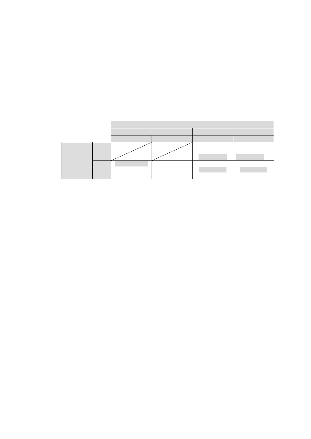
RS-422 Transmission Settings
Route Setting
Direct
Via Main MTX
Within a card
Between cards
Within a card
Between cards
Switching
Mode
Setting
ON
I/O delay: Large
Asynchronous
Data loss: No
I/O delay: Large
Asynchronous
Data loss: No
OFF
I/O delay: Small
Asynchronous
Data loss: Yes
I/O delay: Large
Asynchronous
Data loss: Yes
I/O delay: Large
Synchronous
Data loss: Yes
I/O delay: Large
Synchronous
Data loss: Yes
I/O delay: The minimum delay is approx. 190 nsec (Small) when an input and output ports are on the
same card. In other cases, the delay becomes larger, from 0.8 msec (Large).
Synchronous / Asynchronous: This indicates whether data switches are always synchronizes with
audio and video switches. “Asynchronous“ means data switches may be delayed by one field (or one
frame) relative to video or audio switches.
Data loss: This indicates whether data loss can occur during switches.
The Route and Switching Mode settings allow you to minimize I/O delay or to prevent data
loss or corruption during switches.
They can be set in the [Web-based Control: RS-422 Settings page].
To transmit data with minimum delay:
>> Select Direct under Route.
To guarantee transmission reliability:
>> Set Switching Mode to ON and specify Data Rate, Parity and Stop Bit.
The table below shows details on how data switches are performed within the same card or
between cards depending on the Route and Switching Mode settings.
35
Page 36
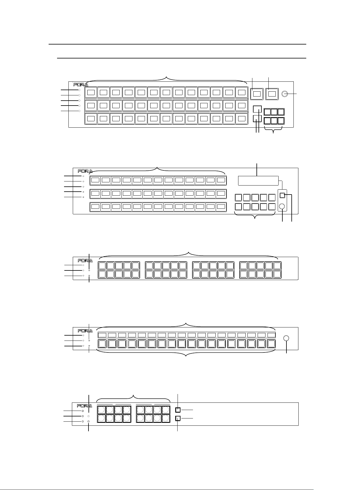
POWER
BUSY SETUP
LOCK RESET
MFR-40RU
REMOTE CONTROL UNIT
B A F (2)
E D C
POWER
BUSY SETUP
LOCK RESET
MFR-18RU
REMOTE CONTROL UNIT
B
A
G E D
C
F (2)
I
PAGE A
(HOLD 3SEC)
PAGE B
LOCK RESET
POWER
BUSY SETUP
LOCK DEST
(HOLD 3SEC)
LOCK PANL
A B
REMOTE CONTROL UNIT
MFR-16RU
B
A E D C F (3) L K
RESET
CANCEL
MFR-39RU
REMOTE CONTROL UNIT
POWER
BUSY
LOCK
SETUP
B
A
F (1)
E
D
C
I
J H F (2)
B
A
F (1)
E
D
C I V
F (2)
POWER
BUSY
LOCK
SETUP
RESET
DEST SRC
A
B
C
D
PAGE
MFR-39RUAREMOTE COMTROL UNIT
U
W
2-6. Remote Control Panel
2-6-1. Front Panel
MFR-39RUA
MFR-39RU
MFR-40RU
MFR-18RU/18RUA
MFR-16RU
36
Page 37
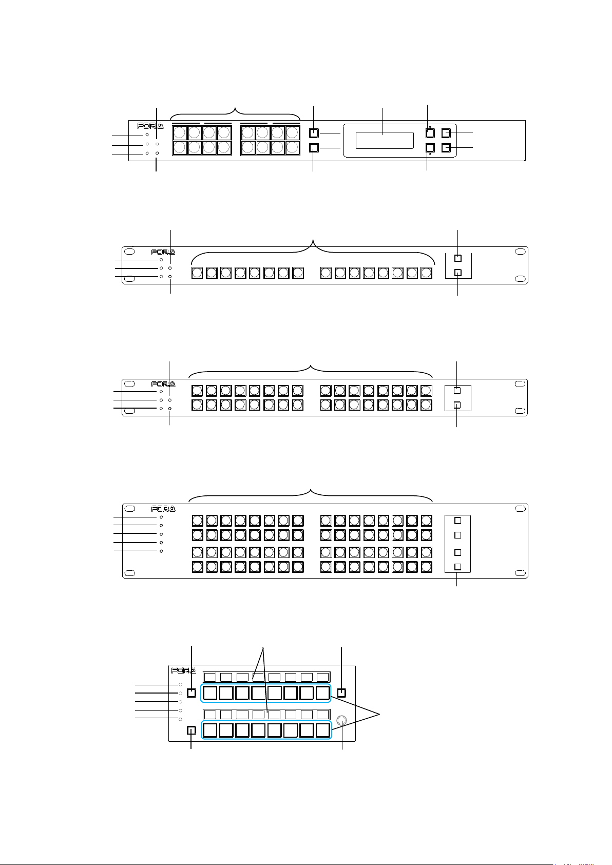
PAGE A
(HOLD 3SE C)
PAGE B
LOCK RESET
POWER
BUSY SETUP
LOCK DEST
(HOLD 3SE C)
LOCK PANL
CANCEL
ENTER
A B
MFR-16RUD
REMOTE CONTROL UNIT
B A E D C
F (3)
L
K
M
O N J
P
POWER
BUSY SE TUP
LOCK RES ET
MFR-16RUW
FUNCTION
1
2
REMOTE CONT ROL UNIT
B
A
E
D
C
F (3)
Q
Q
POWER
BUSY SETUP
LOCK RESET
FUNCTION
1
2
REMOTE CONTROL UNIT
MFR-32RUW
B
A E D C F (3) Q Q
MFR-64RUWREMOTE CONTROL UNIT
1
2
1
2
POWER
BUSY
LOCK
SETUP
RESET
FUNC TION
B A D
F (3) Q C
E
B
A D C E G T F (2)
I R S
MFR-16RUTA
REMOTE CONTROL UNIT
LOCK
POWER
BUSY
PAGE A
LOCK
SETUP
RESET
PAGE B
MFR-16RUD
MFR-16RUW
MFR-32RUW
MFR-64RUW
MFR-16RUTA
37
Page 38
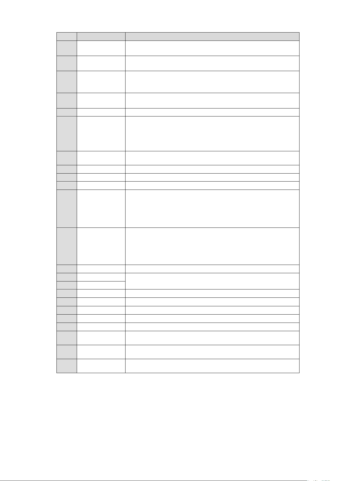
No.
Item
Description
A
POWER
Displays the power status.
► See the table on the next page for details on indications.
B
BUSY
Displays the flash memory writing status of backup settings.
► See the table on the next page for details on indications.
C
LOCK
Displays the LOCK status.
► See the table on the next page for details on indications.
► See section 6-3. "Lock" for details on the lock function.
D
SETUP
Used for IP address or other settings.
► See section 5-6. "Setup Menu." for details on the SETUP menu.
E
RESET
Used to re-initialize the remote control panel.
F
Buttons
All buttons are user assignable.
(1) 7-color selectable button name indication (red, green, yellow,
blue, white, cyan or magenta) (hereafter called LCD)
(2) 3-color selectable button illumination (red, green or orange)
(3) Green illumination
G
NAME DISPLAY
7-color selectable button name/assignment indications (red, green,
yellow, blue, white, cyan or magenta)
H
MENU
Displays setting menus and status.
I
CONTROL
Used to enter menu settings.
J
CANCEL
Used to cancel menu settings.
K
PAGE A /
LOCK PANL
Page switch button.
Pressing the button switches Page 1 and Page 2 of Group A.
The button is unlit if Page 1 is applied.
The button is lit orange if Page 2 is applied.
To use the button as LOCK LOCAL, press and hold down (within 3
seconds). (*)
L
PAGE B /
LOCK DEST
Page switch button.
Pressing the button switches Page 1 and Page 2 of Group B.
The button is unlit if Page 1 is applied.
The button is lit orange if Page 2 is applied.
To use the button as LOCK ALL, press and hold down (within 3
seconds). (*)
M
Display
Displays crosspoints and button assignments.
N
↑
UP / DOWN buttons, used to select items to be viewed on the
Display.
O ↓ P
ENTER
Used to confirm settings on the Display.
Q
FUNCTION
Function assignable buttons. (Green illumination)
R
PAGE A
If enabled, Group A pages can be controlled.
S
PAGE B
If enabled, Group B pages can be controlled.
T
LOCK
Lock function assignable button
U
Current DEST
button
Displays the current destination channel.
V
Current SRC
button
Displays the current source channel.
W
Current PAGE
display
Displays the current page.
(*) PAGE Switch and LOCK features are initially enabled and can be disabled in the [Web-based Control:
Assign Function page], respectively.
38
Page 39
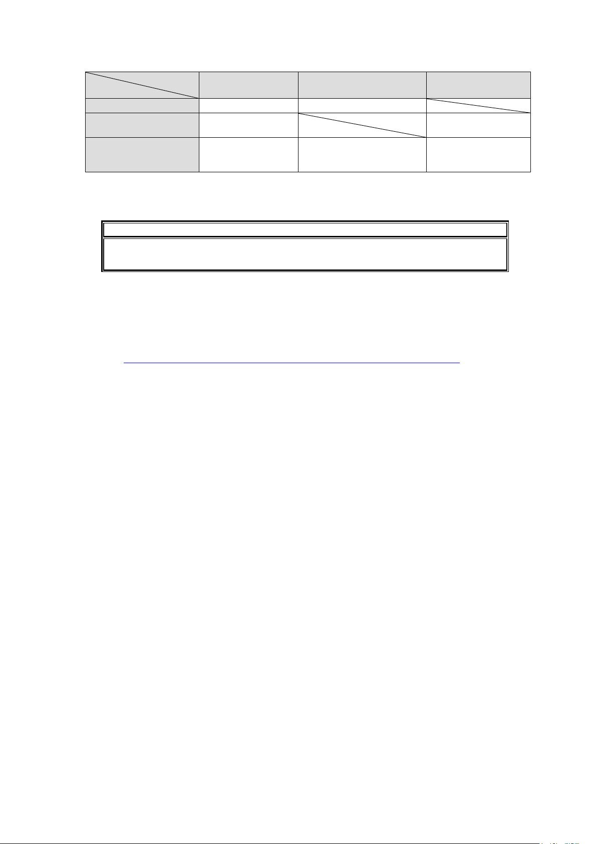
Color indications on the MFR-RU front panel
LED color
LED
Green
Red
Orange
POWER LED
Normal
Power alarm
BUSY LED
Normal processing
Writing to flash
memory
LOCK LED
Operation locked by
Lock Local
Operation locked by Lock
All, or locked by Lock
Other from another unit.
Lock Other is
activated in own unit.
IMPORTANT
After finishing settings, do not power OFF the unit while BUSY LED is lit orange,
since the system is writing to Flash. (It takes about two minutes at max.)
* LOCK LED flashes if the locked operation is accessed. The operation will not perform.
* POWER LED lights red if the unit is turned on while it is not connected to a network.
* All indicators, POWER, BUSY and LOCK, light orange while the SETUP menu is displayed.
Changing Button Labels
Button labels can be changed on user-assignable buttons. Utilize button label templates in
the FOR-A web site. To remove button caps, use an optional tool.
To download button label templates, go to the MFR-RU Series page in the FOR-A site and
open the Documents tab.
URL: http://www.for-a.com/products/mfr_ru_series/professional_router_p.html
39
Page 40
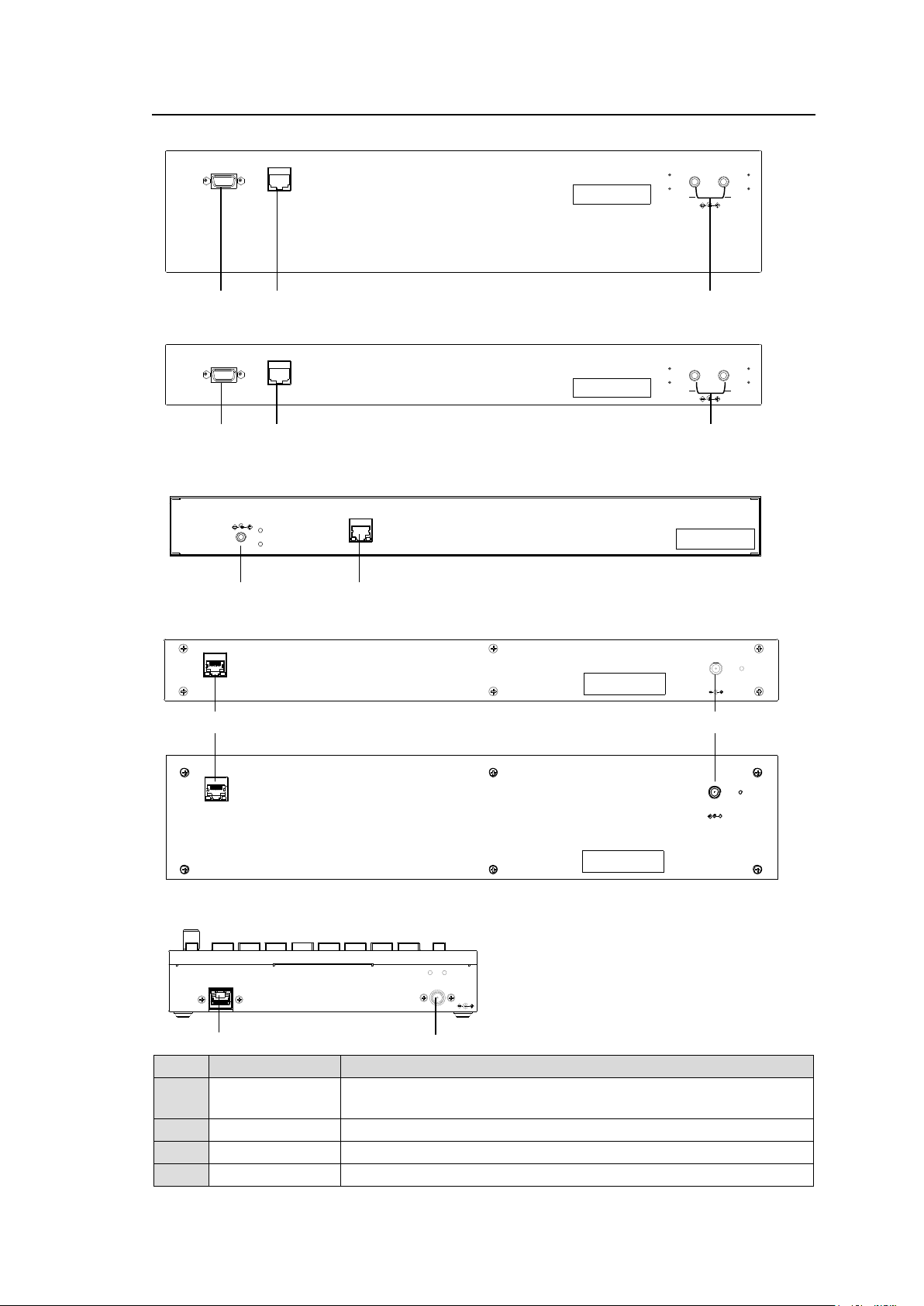
2-6-2. Rear Panel
No.
Item
Description
A
MFR-LAN *1
Used to connect the MFR main unit
Ethernet port (10/100BASE-TX)
B
SERVICE
Used for maintenance only. Do not use.
C
DC 12 V IN 1,2
Used to supply 12 V DC power.
D
DC 12 V IN
Used to supply 12 V DC power.
DC12V IN
2 1
SERVICE
MFR-LAN
B A C
DC12V IN
MFR- LAN
A
D
DC12V IN
2 1
SERVICE
MFR-LAN
A C B
DC12V IN
MFR-LAN
A
D
RATING LABEL
DC12V IN
MFR-LAN
MFR-LAN
DC12V IN
A
D
MFR-39RU / 39RUA
MFR-40RU / MFR-18RU/ MFR-18RUA
MFR-16RU / MFR-16RUD
MFR-16/32/64RUW
MFR-16RUTA
*1 The MFR-LAN connector may be labeled 10/100BASE-T on the previous model.
40
Page 41
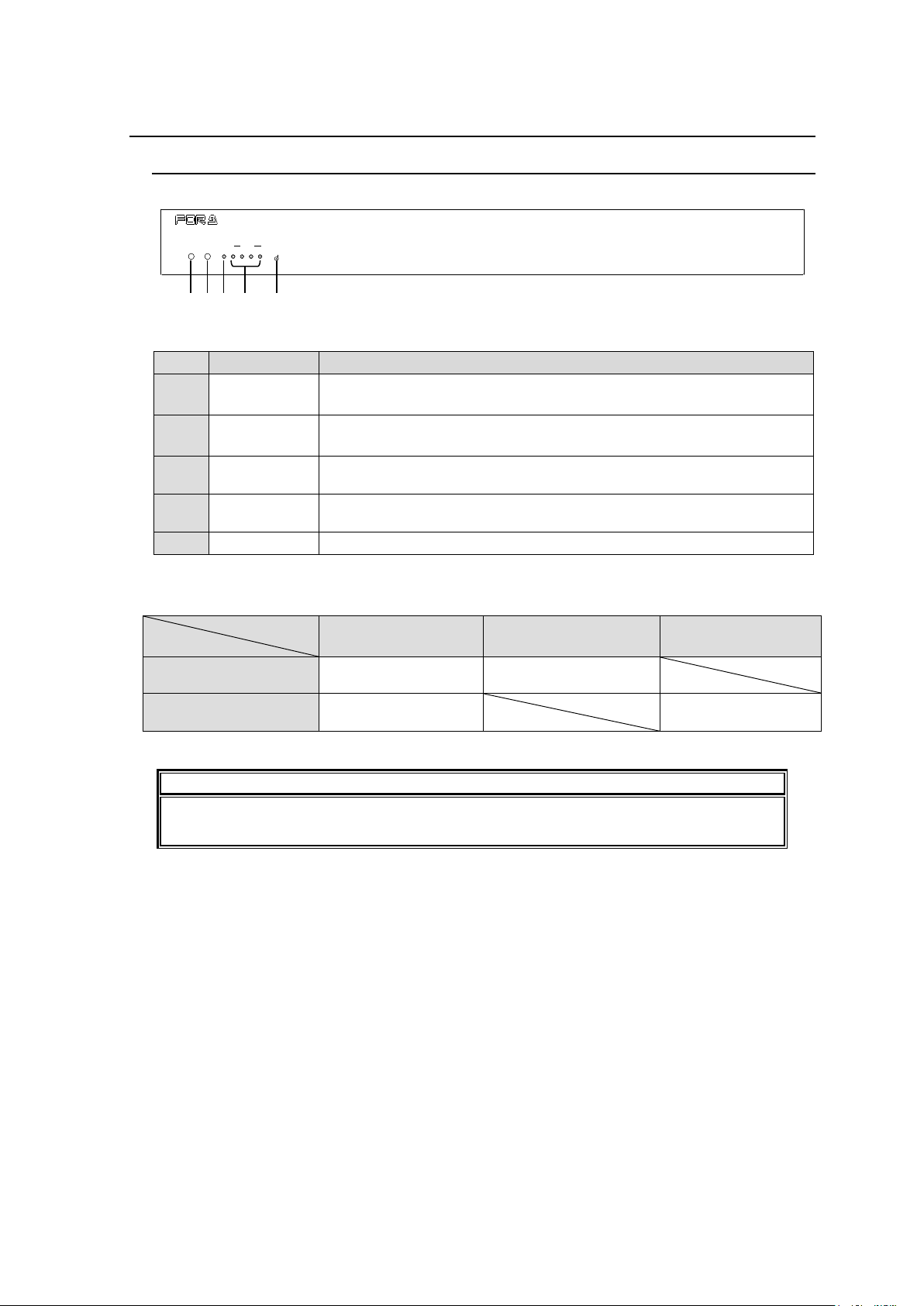
No.
Item
Description
A
POWER
Displays the power status.
► See the table below for details on indications.
B
BUSY
Displays the flash memory writing status of backup settings.
► See the table below for details on indications.
C
GPI
When the GPI function is assigned using the Web-based Control, the
LED lights green. The LED remains unlit when there is no assignment.
D
SERIAL 1-4
When a serial port is assigned using the Web-based Control, the LED
lights green. The LED remains unlit when there is no assignment.
E
RESET
Used to re-initialize the GPI unit.
LED Color
LED
Green
Red
Orange
POWER
Normal
Power alarm
BUSY
Normal processing
Writing to flash
memory
IMPORTANT
After finishing settings, do not power OFF the unit while BUSY LED is lit orange,
since the system is writing to Flash. (It takes about two minutes at max.)
POWER BUSY GPI 1 2 3 4
SERIAL
RESET
MFR-GPI
GPI UNIT
A B D E C
2-7. MFR-GPI
2-7-1. Front Panel
Color indications on the MFR-GUI front panel
* POWER LED lights red if the unit is turned on but is unconnected to a network.
41
Page 42
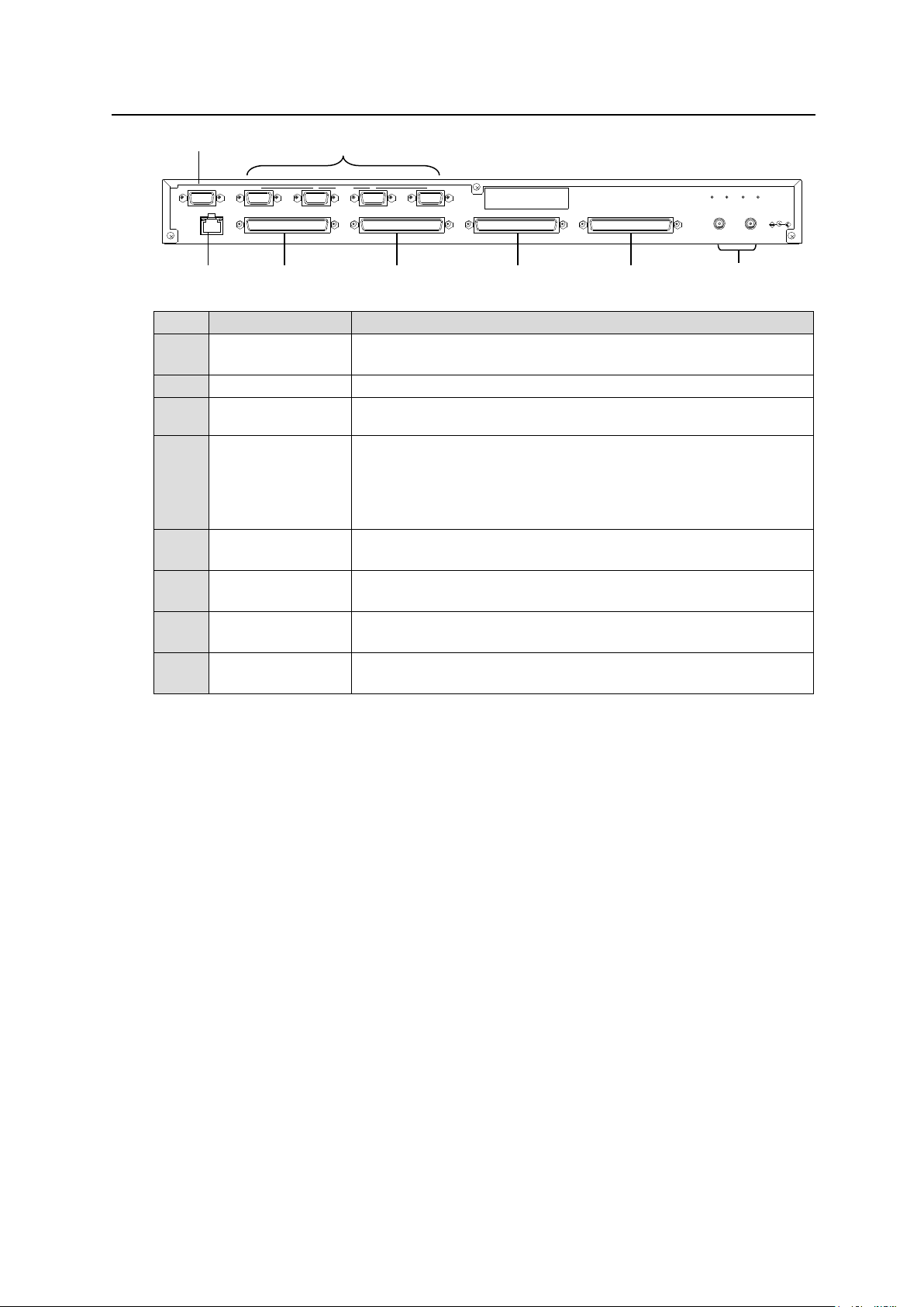
2-7-2. Rear Panel
No.
Item
Description
A
MFR-LAN *1
Used to connect the MFR main unit
Ethernet port (10/100BASE-TX)
B
SERVICE
Used for maintenance only. Do not use.
C
DC 12 V IN 1 and
2
Used to supply 12 V DC power.
D
SERIAL1 to 4
Used for serial interface control. The default setting is RS-422.
RS-232C is also selectable using switches on the internal card.
► See section 2-7-4. “Switches on the Card.”
Pin assignments are the same as those on the MFR main unit.
► See section 2-2-1. “Interfaces.”
E
GPI 1
(Port no: 1)
Used for GPI input / output connections.
(32 total assignable inputs and outputs)
F
GPI 2
(Port no: 2)
Used for GPI input / output connections.
(32 total assignable inputs and outputs)
G
GPI 3
(Port no: 3)
Used for GPI input / output connections.
(32 total assignable inputs and outputs)
H
GPI 4
(Port no: 4)
Used for GPI input / output connections.
(32 total assignable inputs and outputs)
2 -DC12V IN- 1
SERVICE 1 2 3 4
GPI 2GPI 1 GPI 3 GPI 4
RATING LABEL
SERIAL
MFR-LAN
A B C D E F G
H
*1 The MFR-LAN connector may be labeled 10/100BASE-T on the previous model.
42
Page 43
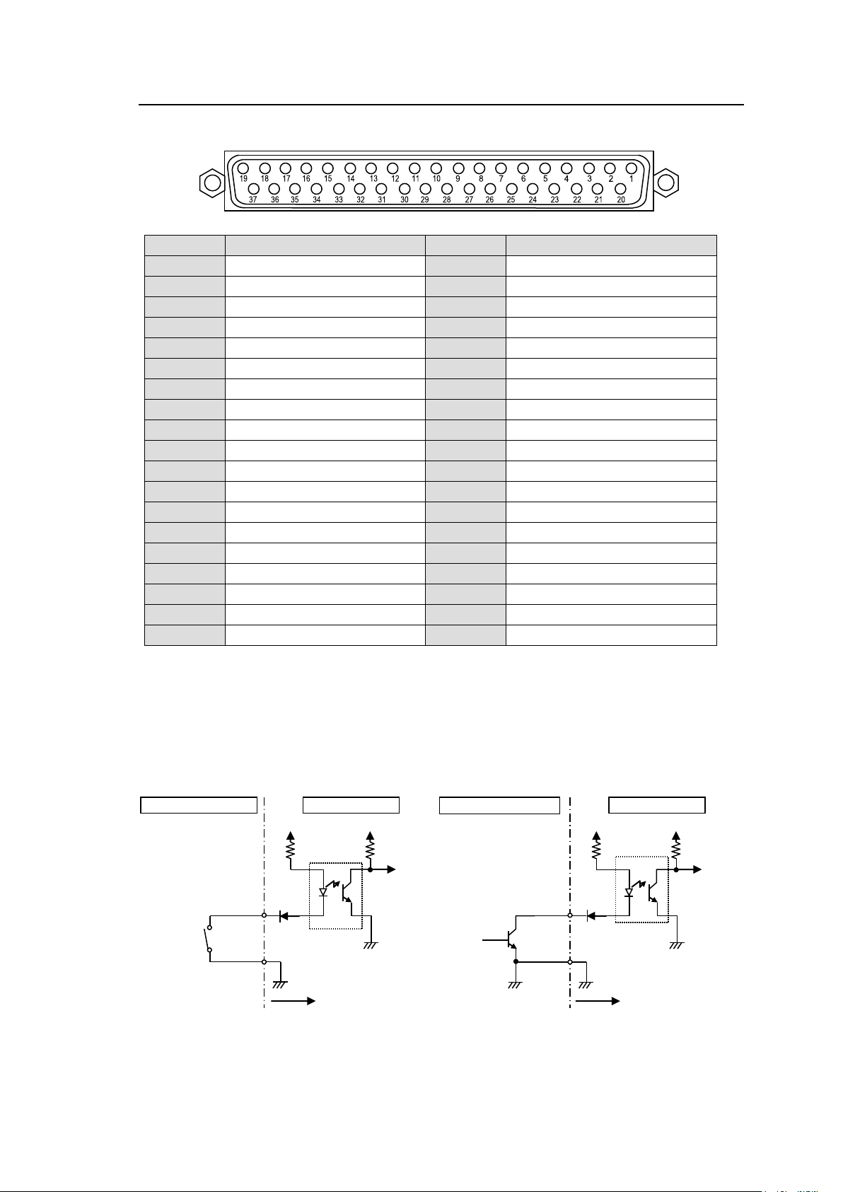
2-7-3. Interfaces (MFR-GPI)
Pin No.
Signal
Pin No.
Signal
1
GPI_IN / TALLY_OUT 01 #
20
GPI_IN / TALLY_OUT 20 #
2
GPI_IN / TALLY_OUT 02 #
21
GPI_IN / TALLY_OUT 21 #
3
GPI_IN / TALLY_OUT 03 #
22
GPI_IN / TALLY_OUT 22 #
4
GPI_IN / TALLY_OUT 04 #
23
GPI_IN / TALLY_OUT 23 #
5
GPI_IN / TALLY_OUT 05 #
24
GPI_IN / TALLY_OUT 24 #
6
GPI_IN / TALLY_OUT 06 #
25
GPI_IN / TALLY_OUT 25 #
7
GPI_IN / TALLY_OUT 07 #
26
GPI_IN / TALLY_OUT 26 #
8
GPI_IN / TALLY_OUT 08 #
27
GPI_IN / TALLY_OUT 27 #
9
GPI_IN / TALLY_OUT 09 #
28
GPI_IN / TALLY_OUT 28 #
10
GPI_IN / TALLY_OUT 10 #
29
GPI_IN / TALLY_OUT 29 #
11
GPI_IN / TALLY_OUT 11 #
30
GPI_IN / TALLY_OUT 30 #
12
GPI_IN / TALLY_OUT 12 #
31
GPI_IN / TALLY_OUT 31 #
13
GPI_IN / TALLY_OUT 13 #
32
GPI_IN / TALLY_OUT 32 #
14
GPI_IN / TALLY_OUT 14 #
33
Frame ground
15
GPI_IN / TALLY_OUT 15 #
34
Frame ground
16
GPI_IN / TALLY_OUT 16 #
35
Frame ground
17
GPI_IN / TALLY_OUT 17 #
36
+4.8V output
18
GPI_IN / TALLY_OUT 18 #
37
+4.8V output
19
GPI_IN / TALLY_OUT 19 #
MFR-GPI
VCC
VCC
External device
Switch or relay
MFR-GPI
VCC
VCC
External device
Open Collector
GPI IN / TALLY OUT Connector (37-pin D-sub, female)
* The symbol "#" at the end of signals represents the port number (1, 2, 3 or 4).
* The maximum total output current for all +4.8 V outputs is 1.5 A.
* The GPI input pulse width should be 54 ms or more.
GPI IN Circuits
43
Page 44
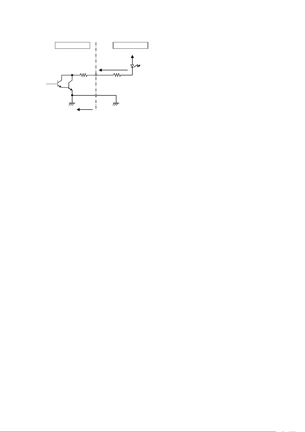
GPI OUT / TALLY OUT Circuit
External device
Max. voltage: 40 V
MFR-GPI
Max. current:
100 mA
10Ω
* The voltage is about 0.9 V when turned-on.
44
Page 45
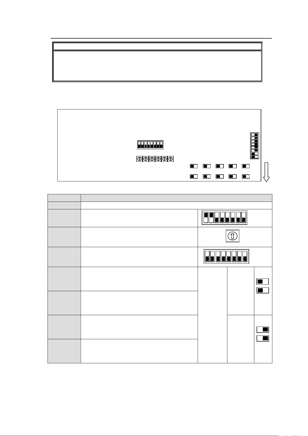
2-7-4. Switches on the Card
CAUTION
Do not access internal cards or make connections with the unit powered ON. Always
power OFF all connected units / disconnect power cords prior to accessing the interior.
Further note that adjustments and maintenance should only be performed by qualified
technical personnel familiar with FOR-A equipment.
Switch
Function / Settings
S2, S3
Used for maintenance. Do not use.
S4
Used for maintenance. Do not use. (The factory
default setting is as shown at right. The black
boxes (■) represent switches.)
S5, S6, S7,
S8, S9, S10
Used for IP address setting.
S11
Used for maintenance. Do not use.
S12, S14
Used to select RS-232C/RS-422 for SERIAL 1.
The default setting is RS-422 (both switches to
the right). To change to RS-232C, set both
switches to the left.
Switch
Settings
RS-232C
(Factory
default
setting)
S13, S15
Used to select RS-232C/RS-422 for SERIAL 2.
The default setting is RS-422 (both switches to
the right). To change to RS-232C, set both
switches to the left.
S16, S18
Used to select RS-232C/RS-422 for SERIAL 3.
The default setting is RS-422 (both switches to
the right). To change to RS-232C, set both
switches to the left.
RS-422
S17, S19
Used to select RS-232C/RS-422 for SERIAL 4.
The default setting is RS-422 (both switches to
the right). To change to RS-232C, set both
switches to the left.
Front
S12
S13
S16
S17
S10
S9
S8
S7
S6
S5
S11
S2
S14
S15
S18
S19
S3
S4
ON
OFF
422
422
232C
232C
422
232C
422
232C
422
232C
422
232C
422
422
232C
232C
422
232C
422
232C
422
232C
422
232C
ON
OFF
OFF
ON
OFF
ON
Remove the two screws on both sides of the MFR-GPI to access the internal card as shown
below. The figure below shows the factory default switch settings.
45
Page 46
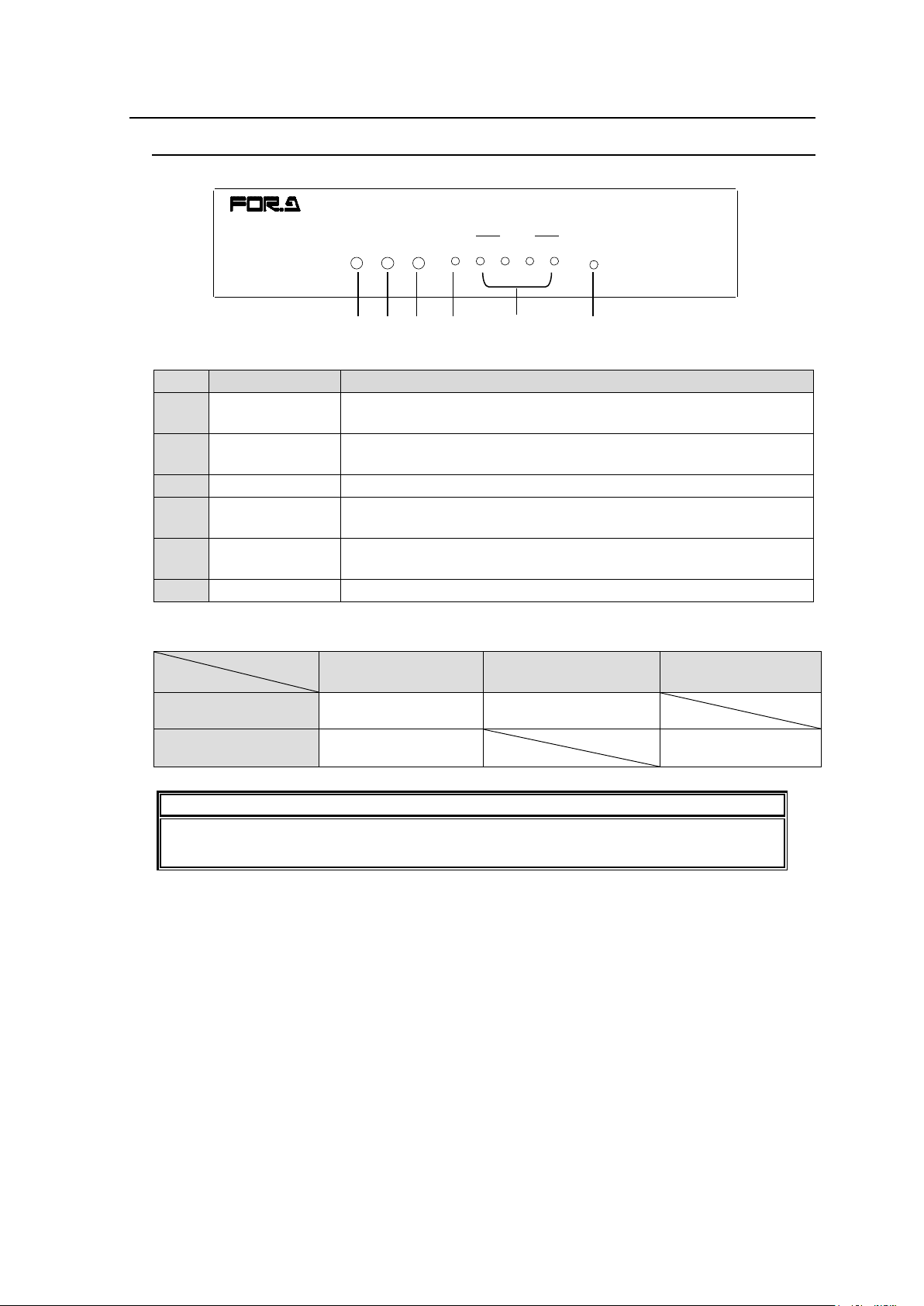
2-8. MFR-TALM
No.
Item
Description
A
POWER
Displays the power status.
► See the table below for details on indications.
B
BUSY
Displays the flash memory writing status of backup settings.
► See the table below for details on indications.
C
REF IN
Lights green when an external reference signal is present.
D
GPI
Lights green a GPI function is assigned.
Turns off when no GPI function is assigned.
E
RS-422 1-4
Lights green when a port function is assigned.
Turns off when no port function is assigned.
F
RESET
Resets MFR-TALM.
LED Color
LED
Green
Red
Orange
POWER
Normal
Power alarm
BUSY
Normal processing
Writing to flash
memory
IMPORTANT
Do not power off the unit while BUSY LED is lit orange (writing to the flash memory,
about 2 seconds at most).
POWER BUSY REF IN GPI RS-422 RESET
21 43
TALLY MANA GER UNI T
MFR-TALM
A B E F C
D
2-8-1. Front Panel
Color indications on the MFR-TALM front panel
46
Page 47
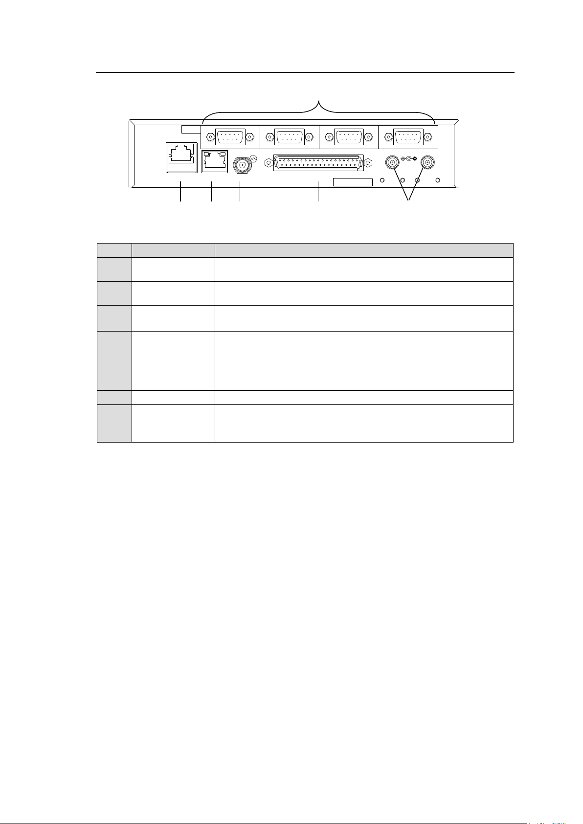
2-8-2. Rear Panel
No.
Item
Description
A
PC-LAN
Ethernet port for connection to PC or other external unit
(10/100BASE-TX, RJ-45)
B
MFR-LAN
Ethernet port for connection to MFR main unit
(10/100/1000BASE-T, RJ-45)
C
REF IN
Used to input a reference signal (BB or Tri-level sync signal)
(with loop-through. Terminate with 75Ω terminator, if unused.)
D
GPI
Used to input/output GPI signals for external control.
(32 total assignable inputs and outputs)
Pin assignments are the same as those of the MFR-GPI
connectors.
► See section 2-7-3. "Interfaces (MFR-GPI)."
E
DC 12 V IN 1,2
Used to supply 12 V DC power.
F
RS-422 1-4
Used for RS-422 interface control.
Pin assignments are the same as those of the MFR main unit.
► See section 2-2-1. "Interfaces."
SER. NO.
2
4
3
21
GPIREF INMFR-LANPC-LAN
1
DC12V IN
RS-422
A E F B C
D
47
Page 48
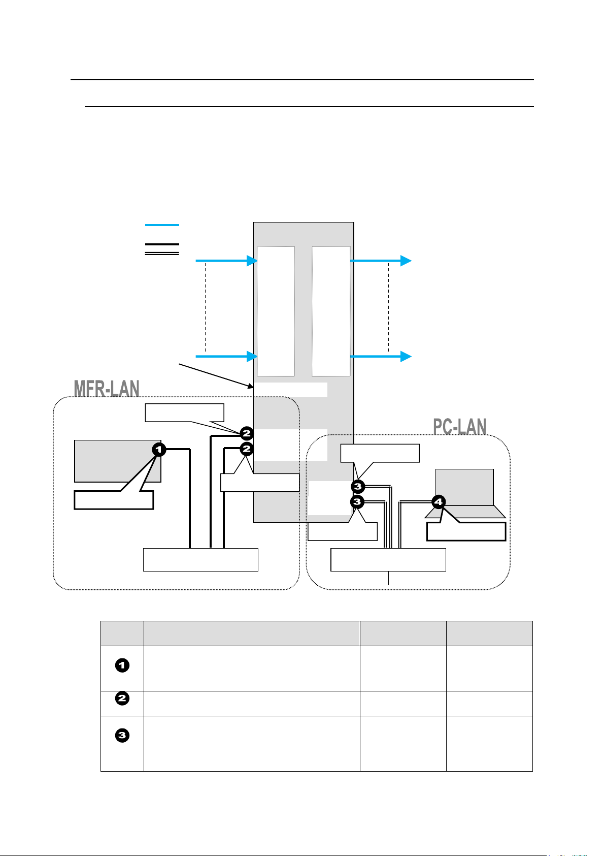
3. System Configuration Example
Port
RU Front Panel
Web-based
Control
Sec. in Web
Control Manual
MFR-39RUA: See sec. 5-4-4.
MFR-39RU: See sec. 5-6-1.
MFR-18RU/18RUA: See sec. 5-8-1 and 5-8-2
Other RUs: See sec. 5-10-1 and 5-10-2.
RU Settings
page
6-3
---
MU Settings
page
5-2
MFR-39RUA: See sec. 5-4-4(display only).
MFR-39RU: See sec. 5-6-3(display only).
MFR-18RU/18RUA: See sec. 5-8-1 (display
only).
Other RUs: See sec. 5-10-1 (display only).
Network
Settings page
4-1-7
MFR-LAN(CPU1)
MFR-LAN(CPU2)
MFR-xxRU
SDI/ AES SDI/ AES
REF IN
MFR-5000
IN1
|
|
|
|
I
|
|
I
|
|
IN128
OUT1
|
|
|
|
I
|
I
|
|
I
OUT128
Ethernet Hub (MFR-LAN)
Ethernet Hub (PC-LAN)
PC
MFR Web-based
Control
BB
VIDEO(SDI)
LAN (MFR-LAN)
LAN (PC LAN)
LAN port label indications have
been changed.
TO RU >> MFR-LAN (CPU1, 2)
TO PC >> PC-LAN
192.168.1.XX
192.168.1.12
192.168.1.11
192.168.1.10
192.168.1.XX
PC-LAN1
PC-LAN2
192.168.1.13
3-1. Basic Configuration
The block diagram below shows an example of the basic MFR routing system that consists of an
MFR-5000, Remote Unit and the Web-based Control accessed from a computer.
Make sure to connect both MFR-LANs (CPU1) and (CPU2) to a LAN respectively for CPU
redundancy. Their LAN connections must be separated from the network segment of PC-LAN
and other devices. (Default IP addresses (Net mask: 255.255.255.0) are used in the
configuration example below.)
LAN Port Settings
48
Page 49
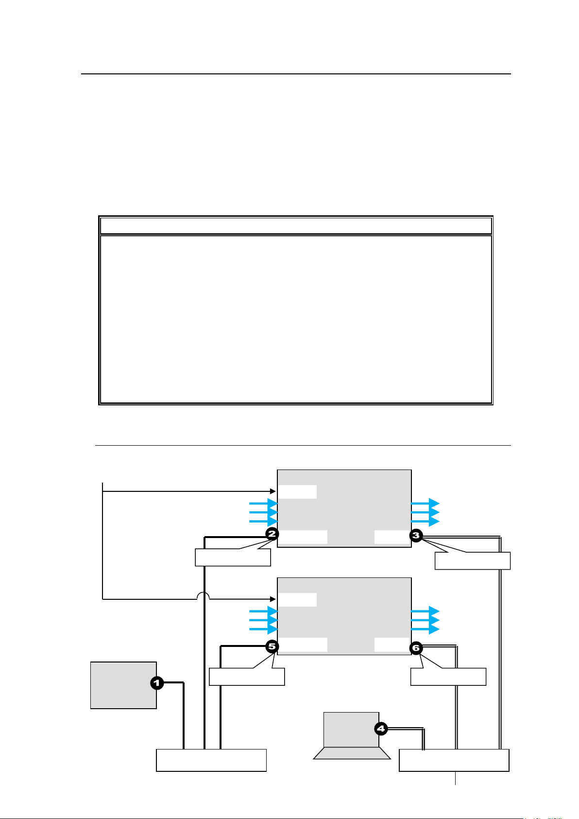
3-2. Main Unit Linking
Parallel Link:
Controls several MFR-5000 units at the same time.
Controls an MFR-5000 and MFR-8000 units at the same time.
Expanded Matrix:
Creates an expanded virtual matrix by linking MFR-5000 units.
Main Unit Link Specifications
Main Unit Link systems are set and controlled through a specified master unit.
Up to 4 MFR-5000 units can be linked within a system.
Parallel links using each one of MFR-5000 and one MFR-8000 are possible.
MFR-5000 and other MFR main units (MFR-3000/ 3232/ 3216/ 1616/ 1616R/
1616A/ 3216RPS/ 3232RPS) cannot be linked to each other.
Only SDI signals can be routed in Expanded Matrix systems. However,
MFR-5000 inputs and outputs not used in the Main Unit Link can be assigned
independently and used as paralleled link matrix, managing both SDI and AES
signals. (Note that, in such cases, ADAO cards output BLACK signals from SDI
OUT.)
All MFR main units in a link system must be linked together and independent units
cannot exist in the system.
Refer to Firmware / Software Versions and Supported Hardware / Features (p. 3)
for details on the supported version.
MFR-xxRU
Ethernet Hub (MFR-LAN)
Ethernet Hub (PC-LAN)
PC
MFR Web-based
Control
BB
MFR-LAN
PC-LAN
SDI
signal
REF IN
MFR-5000
(Master)
SDI
signal
192.168.1.12
192.168.1.10
192.168.1.13
192.168.1.15
MFR-LAN
PC-LAN
SDI
signal
REF IN
MFR-5000
SDI
signal
The Main Unit Link feature allows you to control multiple MFR-5000 units at the same time.
Two types of system configurations are available:
Note that each Expanded Matrix system requires specific BNC connections. IP port and SNMP
settings should be performed on each MFR-5000 unit. After these settings are completed, all
linked MFR-5000 units are set and controlled together on the unit that is specified as Master.
3-2-1. Parallel Link System Example
The system example below is a redundant system using two MFR-5000 units.
49
Page 50
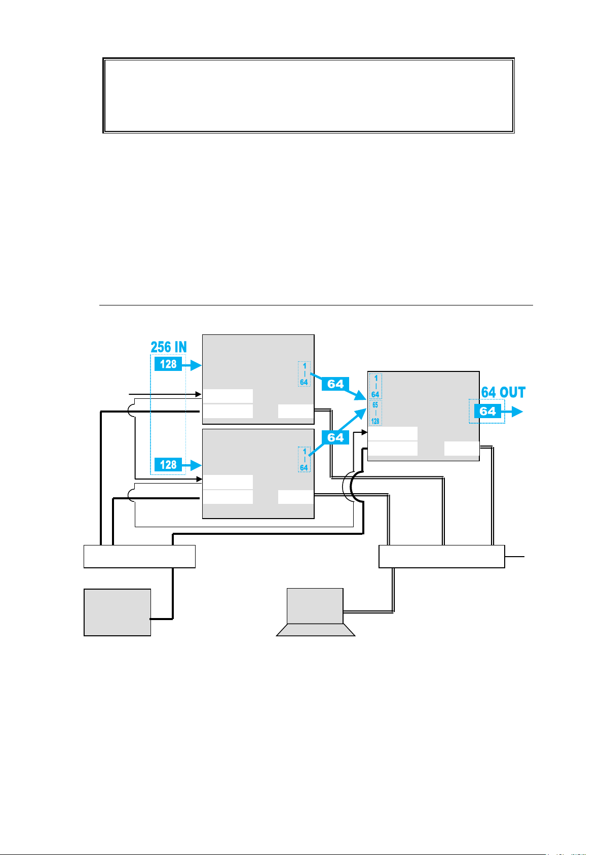
Note that in all MFR-5000 units the IP address of MFR-LAN1 is set to 192.168.1.10
and that of PC-LAN to 192.168.1.12 as factory default. To prevent IP address overlap
in a system, you need to change IP addresses of either unit.
Also note that desired IP addresses can be set for system devices according to your
network conditions.
Setup Procedure
Ethernet Hub (MFR-LAN)
MFR-xxRU
PC
MFR Web-based
Control
BB
MFR-LAN
PC-LAN
REF IN
MFR-5000
MFR-LAN
PC-LAN
REF IN
MFR-5000
MFR-LAN
PC-LAN
REF IN
MFR-5000
Ethernet Hub (PC-LAN)
1) Connect all devices in the MFR system as shown in the figure in the previous page.
Power on the MFR-5000 to be set as a Master, Remote Control unit and PC. Set the IP
addresses for the Remote Control unit (①) and PC (④). Power off the MFR-5000.
2) Power on another MFR-5000. Set the IP addresses (⑤ and ⑥) as shown in the
previous page.
3) Power on the Master MFR-5000.
4) Connect to the Master MFR-5000 Web-based control and open the Build Settings
page. Check on Build Enable to enable the Main Unit Link feature.
See section 11 "Main Unit Link" in the "Web-based Control Operation Manual."
3-2-2. Expanded Matrix System Example
The system example below connects three MFR-5000 units to form a 256 x 64 virtual matrix.
Setup Procedure
1) Connect three MFR-5000 units, one by one, to the MFR system, referring to the
previous chapter for details on to setting network settings. Do not use the same IP
address twice in the system.
2) Connect all three MFR-5000 units to the MFR system. Connect BNC cables based on
SDI signal routing paths.
3) Connect to the Web-based Control of an MFR-5000 and open the Build Settings
page. Check on Build Enable to enable the Main Unit Link feature.
See section 11 "Main Unit Link" in the "Web-based Control Operation Manual."
50
Page 51
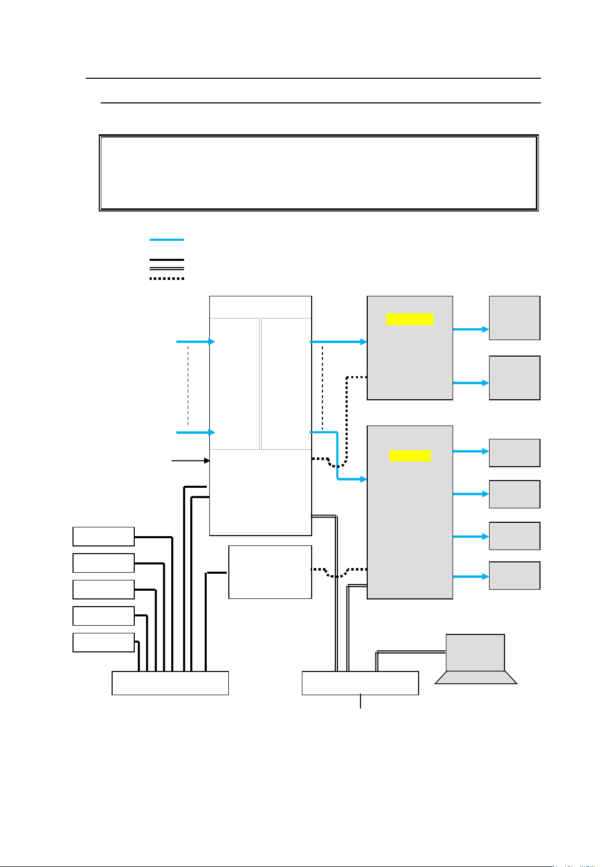
3-3. Signal Name and Tally Link System
To connect a video switcher via serial connection, use the MFR-5000 SERIAL port or
SERIAL1-4 on MFR-GPI. The signal name and tally link system requires an RS-422
interface. Before connecting devices, set the serial port for use to RS-422 using the
switches on the Card.
► See section 2-1-4. CPU Card Switch Settings or 2-7-4. "Switches on the Card."
VIDEO(SDI)
LAN (MFR-LAN)
LAN (PC LAN)
RS-422
MFR-LAN(CPU1)
MFR-LAN(CPU2)
PC-LAN
SERIAL 1
SDI signal SDI signal
REF IN
MFR-5000
MFR-16SDI
IN1
|
|
|
|
I
|
|
I
|
IN128
MFR-16SDO
OUT1
|
|
|
|
I
|
I
|
|
OUT128
PC
MFR Web Control
MV Layout Editor
MFR-GPI
SERIAL
Video Switcher
(HVS-2000)
SERIAL
Multi Viewer
(MV-4200)
RS-422
PGM
Monitor
PRV
Monitor
DVI
DVI
MV
Monitor
MV
Monitor
DVI
MV
Monitor
DVI
MV
Monitor
SDI
SDI
MFR-16RU
MFR-16RUD
MFR-40RU
MFR-18RU
MFR-39RU
Ethernet Hub (MFR-LAN)
Ethernet Hub (PC-LAN)
SERIAL
LAN
3-3-1. Standard Configuration
The block diagram below shows a basic signal name and tally link system.
51
Page 52
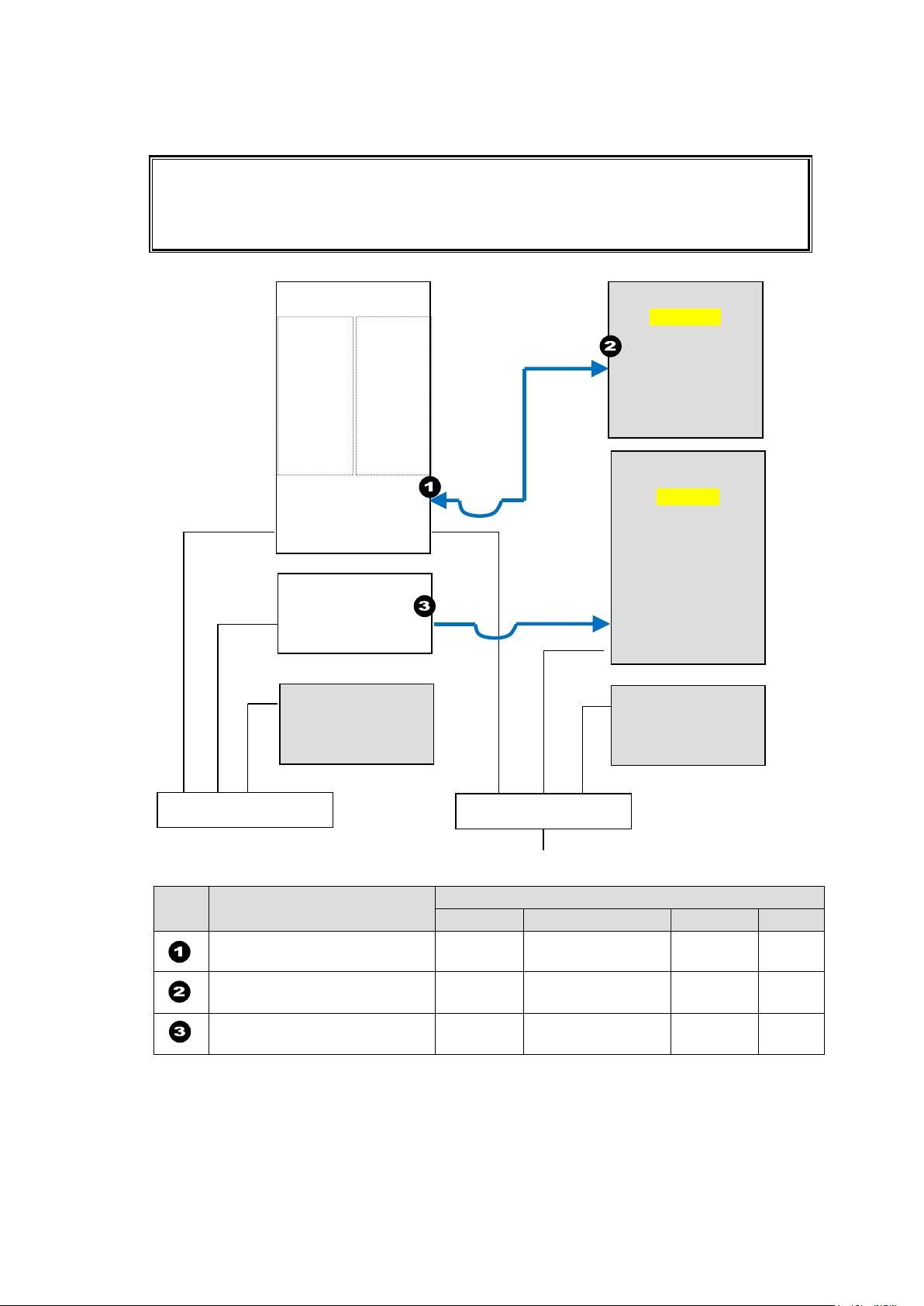
Transmitting Signal Name and Tally Data
Set each serial port following the table on this page using the MFR Web Control and on the
switcher.
Each tally information setting should be performed in the [Web-based Control:Tally
System Settings page].
Port
Menu
[Port Settings] - [Serial Port]
Connector
Function
Baud rate
Parity
Web-based Control
[Router System Settings]
(MU)
-
Router/HVS
connection type 2
38400
NONE
HVS-2000
[SETUP - SYSTEM - RS-422]
ROUTER
38400
NONE
Web-based Control
[Router System Settings]
(GPI)
No. 1
Tally out
(TSL Ver. 3.1)
38400
EVEN
Names
Tallies
Names>>
Switcher tallies
>>
MFR-LAN
PC-LAN
SERIAL 1
MFR-5000
MFR-16SDI
IN1
|
I
|
|
I
|
IN128
MFR-16SDO
OUT1
|
|
I
|
I
|
|
OUT128
MFR-GPI
SERIAL
RS-422(4)
SERIAL
LAN
Video Switcher
(HVS-2000)
Multi Viewer
(MV-4200)
MFR-LAN
PC
(MFR Web-based
Control)
MFR-xxRU
Ethernet Hub (PC-LAN)
Ethernet Hub (MFR-LAN)
The figure below shows the routing of signal name and tally data.
Serial Port Settings
Other Parameter Settings (in HVS-2000)
To receive source names from the router, set [LINK] in the ROUTER NAME menu to [MFR].
52
Page 53
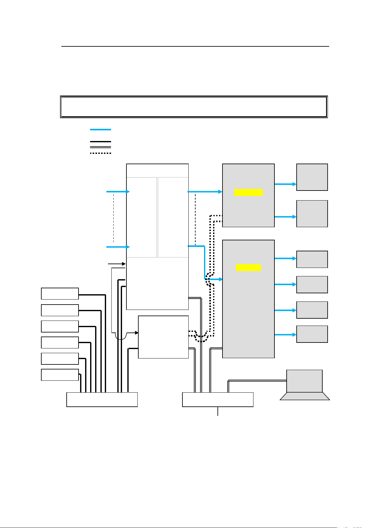
3-3-2. If Configuring an MFR-TALM
Before using an MFR-TALM unit for the system, change Tally Control Unit to MFR-TALM
in the [Main unit Web-based Control: MU Settings page].
VIDEO(SDI)
LAN (MFR-LAN)
LAN (PC LAN)
RS-422
MFR-LAN(CPU1)
MFR-LAN(CPU2)
RS-422(1)
RS-422(2)
SDI signal SDI
signal
REF IN
MFR-5000
MFR-16SDI
IN1
|
|
|
|
I
|
|
I
|
IN128
MFR-16SDO
OUT1
|
|
|
|
I
|
I
|
|
OUT128
PC
MFR Web Control
MV Layout Editor
MFR-TALM
SERIAL
Video Switcher
(HVS-2000)
SERIAL
Multi Viewer
(MV-4200)
RS-422(1)
RS-422(4)
PGM
Monitor
PRV
Monitor
DVI
DVI
MV
Monitor
MV
Monitor
DVI
MV
Monitor
DVI
MV
Monitor
SDI
SDI
MFR-16RU
MFR-16RUD
MFR-40RU
MFR-18RU
MFR-39RU
REF IN
BB
MFR-GPI
PC-LAN
Ethernet Hub (MFR-LAN)
Ethernet Hub (PC-LAN)
LAN
MFR-LAN
PC-LAN
The block diagram below shows an example signal name and tally link system comprised of
a FOR-A video switcher and multiviewer using an MFR-TALM unit. The MFR-TALM is
specifically designed to perform the task of tally data computation, which is ordinarily
undertaken by the MFR main unit, to accelerate the computation. RS-422 ports (1) to (4) are
available for video switcher connection.
53
Page 54
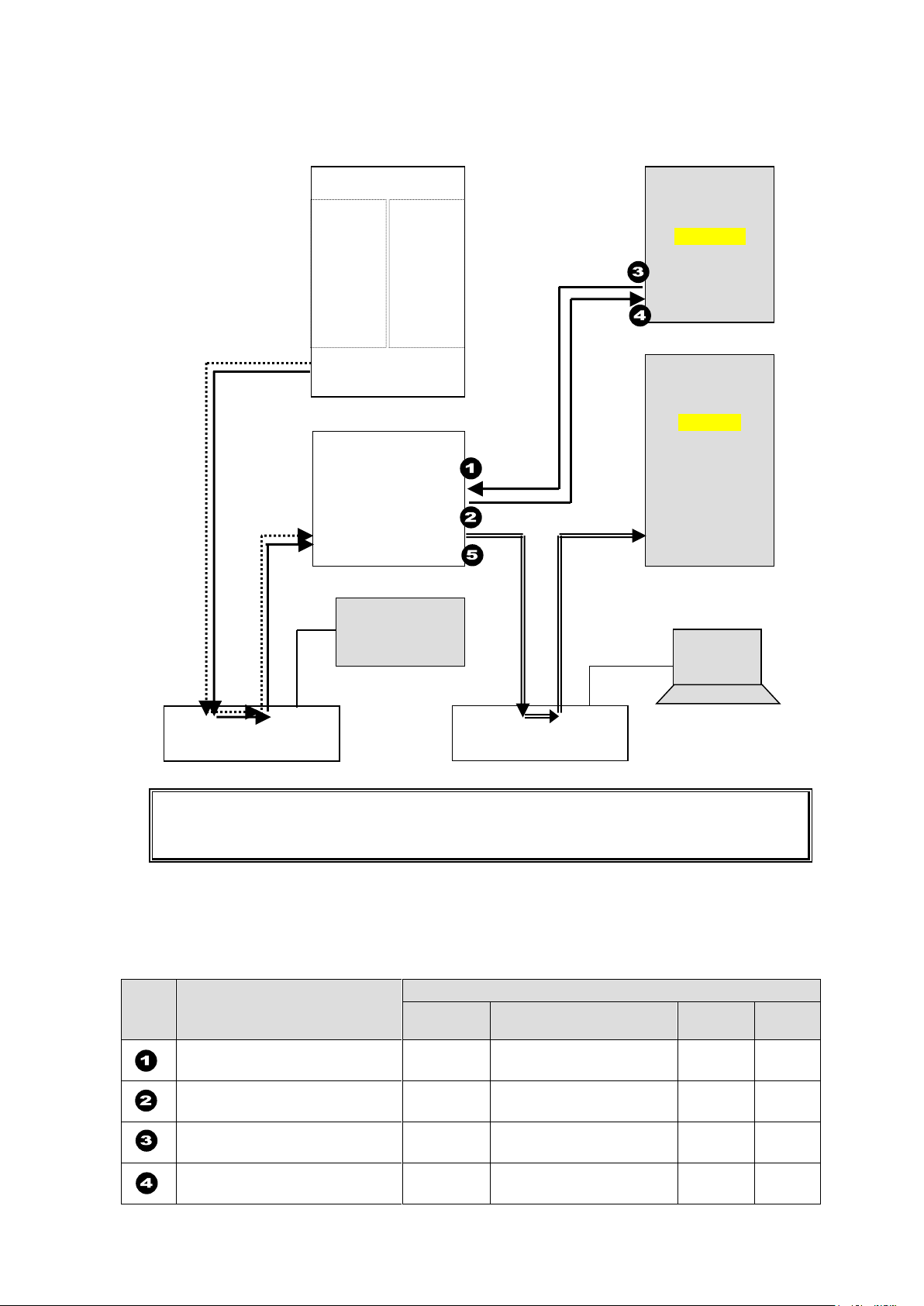
Transmitting Signal Name and Tally Data
Each serial port should be set as shown in the table below in the relevant page of the
MFR-TALM Web-based Control accessed from "http://192.168.1.62" (default IP address)
on your web browser.
Port
Menu
[Port Settings] - [Serial Port]
Connector
Function
Baud
rate
Parity
Web-based Control
[TALM Settings]
No. 1
HVS-TAL Protocol
Reception
38400
EVEN
Web-based Control
[TALM Settings]
No. 2
Router/HVS connection
type 2
38400
NONE
HVS-2000
[SETUP - SYSTEM - RS-422]
No. 1
TALLY
38400
EVEN
HVS-2000
[SETUP - SYSTEM - RS-422]
No. 4
ROUTER
38400
NONE
MFR-LAN
PC-LAN
RS-422(1)
RS-422(2)
MFR-5000
MFR-16SDI
IN1
|
|
|
|
I
|
IN128
MFR-16SDO
OUT1
|
|
|
|
|
|
OUT128
PC
MFR Web Control
MV Layout Editor
MFR-TALM
Video Switcher
(HVS-2000)
SERIAL
Multi Viewer
(MV-4200)
RS-422(1)
RS-422(4)
Ethernet Hub (MFR-LAN)
Ethernet Hub (PC-LAN)
LAN
MFR-LAN
MFR-xxRU
PC-LAN
Router's tally and name data
Switcher's
tally data
Signal name data
Tally and name data
The figure below shows an example signal name and tally data routing system using the
MFR-TALM.
Serial Port Settings
Open the [MFR-TALM Web-based Control: Port Settings page] and perform port settings
under Serial Port.
As for the HVS-2000 unit, perform port setting in the [SETUP - SYSTEM - RS-422] menu.
54
Page 55
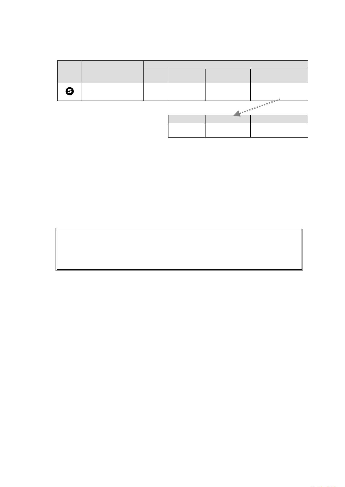
Port
Menu
[Port Settings] - [TCP/IP Port]
Access
Method
IP Address
Port
Function
Web-based Control
[TALM Settings]
Client
(MV
IP address)
(MV TCP/IP
port number)
TSL UMD protocol
V5.0 Tally out
Encode
DLE
Screen No.
Unicode
ON
(Set the same as in
MV)
The tally settings in the MFR system must be entered in the [MFR-TALM Web-based
Control: Tally System Settings page]. When using MFR-TALM for tally control, the [Main
unit Web-based Control: Tally System Settings page] and its subpages are all disabled.
Refer to your mulitviewer's user guide for the details on how to handle tally data on the
multiviewer.
TCP/IP Setting
Open the [MFR-TALM Web-based Control: Port Settings page] and perform port settings
under TCP/IP Port.
Data transmission settings between HVS-2000 and MFR-TALM
<HVS-2000-side>
To receive name data from the router, set LINK in the ROUTER NAME menu to MFR.
Perform the TALLY COLOR and TALLY UNIT settings so that the MFR-TALM unit can
receive switcher tally data.
<MFR-TALM-side>
Open the [MFR-TALM Web-based Control: HVS-TAL Protocol Reception page] and
perform the same tally settings as those in HVS-2000.
55
Page 56
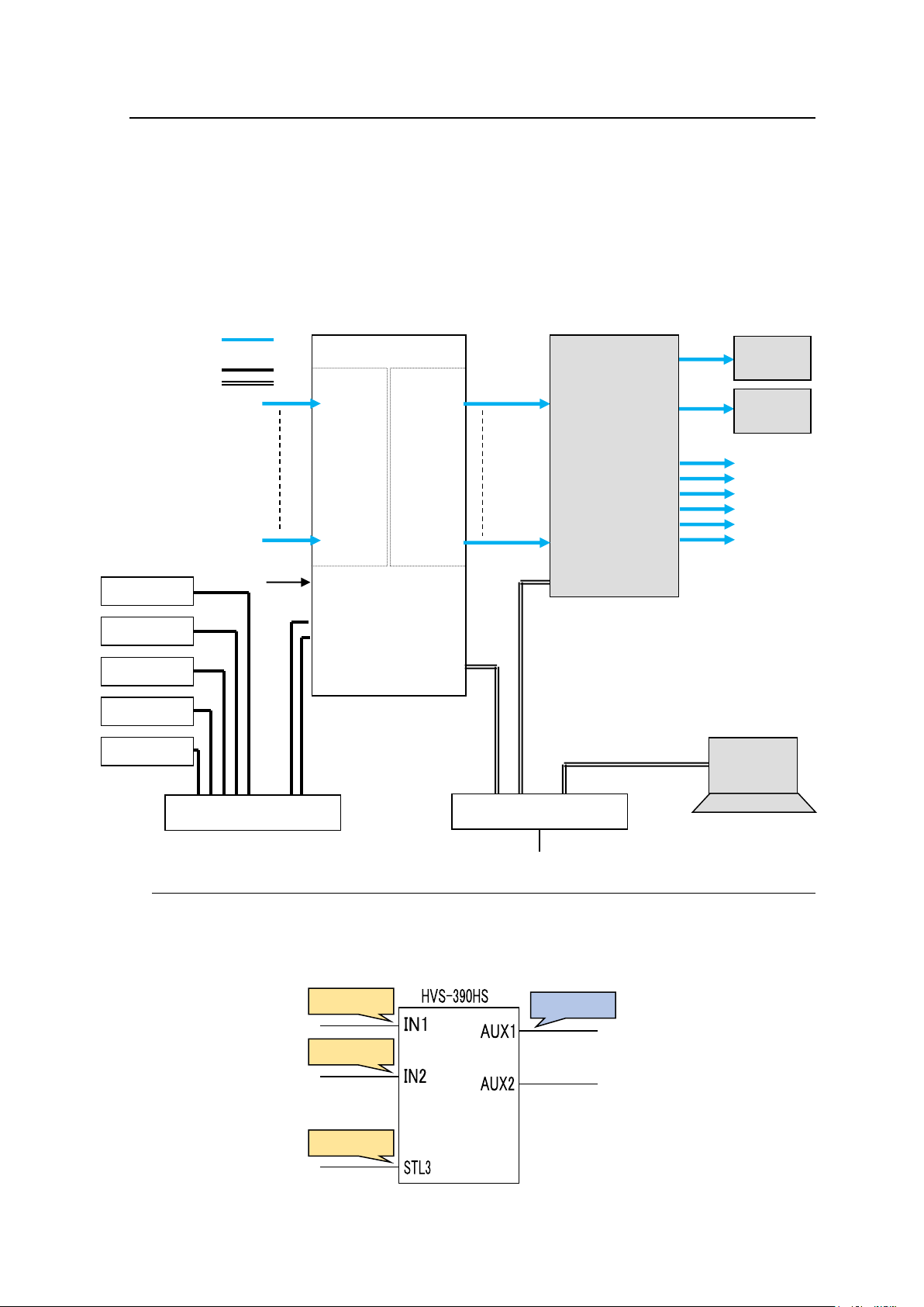
3-4. Switcher's AUX Crosspoints Switching System
DST129
SRC129
SRC130
SRC137
|
|
|
PGM
Monitor
PRV
Monitor
SDI
SDI
VIDEO(SDI)
LAN (MFR-LAN)
LAN (PC LAN)
MFR-LAN(CPU1)
MFR-LAN(CPU2)
PC-LAN
SDI
signals
SDI
signals
REF IN
MFR-5000
MFR-16SDI
IN1
|
|
|
|
I
|
|
I
|
IN128
MFR-16SDO
OUT1
|
|
|
|
I
|
I
|
|
OUT128
PC
MFR Web Control
Video Switcher
(HVS-390HS)
AUX1
AUX2
AUX3
AUX4
AUX5
AUX6
SDI
MFR-16RU
MFR-16RUD
MFR-40RU
MFR-18RU
MFR-39RU
Ethernet Hub (MFR-LAN)
Ethernet Hub (PC-LAN)
LAN
BB
This system enables the following two features:
Switches AUX crosspoints on a switcher using an MFR Series Remote Unit or serial
commands.
Switches AUX crosspoints on a switcher as well as the corresponding crosspoints on the
MFR-5000, if the MFR-5000 provides video souces to the switcher.
Supported switcher: HVS-390HS, HVS-100/110, HVS-2000
System Example
3-4-1. Switching an AUX Bus Signal
Assume that the system is configured as shown below:
AUX1 on the switcher is assigned to DST 129 (Level 1) on the MFR-5000.
IN1-8 and STL(Still) 3 on the switcher are assigned to SRC129-137 on the MFR-5000.
56
Page 57
Setup Settings
IP Address
Port
Protocol
Function
Local Port(MFR)
(Switcher's
IP address)
※
UDP
Editor(HVS)
Select a UDP port number.
Do not use the UDP port number
(Default: 23) already used in the
Server (MFR).
LogicalNo./Name
Switcher Channel
129
SRC 129
IN1
| | |
136
SRC 136
IN8
137
SRC 137
STL3
Switcher
Port
HVS-390HS
8740
HVS-100/110
8740
HVS-2000
53381
1) Connect and assign video signals as shown in the figure above.
2) Device Setup on the MFR-5000:
Connect to the MFR-5000 from the Web-based Control PC and open the [Tally System
Settings - Device Select] page. Select HVS-390HS in the [Switcher] field and click
[Send].
3) Network settings on the MFR-5000:
Open the [Router System Settings - PortSettings] page and set the TCP/IP menu as
shown below.
4) Assign AUX buses and input channels on the switcher to logical destination and sources
channels on the MFR-5000.
<AUX bus assignments>
a) Open the Destination Assignment page.
b) Select HVS(AUX) under Select Table.
c) Set Level to 1.
d) Assign AUX1 to DST 129.
<Input channel assignments>
a) Open the Source Assignment page.
b) Select HVS(AUX) under Select Table.
c) Set Level to 1.
d) Assign input channels to MFR sources as shown below.
5) Settings on the switcher:
Open the [SETUP - EXT I/F - EDITOR] menu on the HVS-390HS.
Change [TYPE] to [DVS] and [ENABLE] to [ON].
After above setup settings are complete:
If SRC 129 is selected for DST 129,
AUX1 outputs IN1 video on the switcher.
If SRC 137 is selected for DST 129,
AUX1 outputs Still 3 video on the switcher.
If IN4 is selected for AUX1 on the switcher,
SRC 132 is selected for DST 129 on the MFR-5000.
57
Page 58
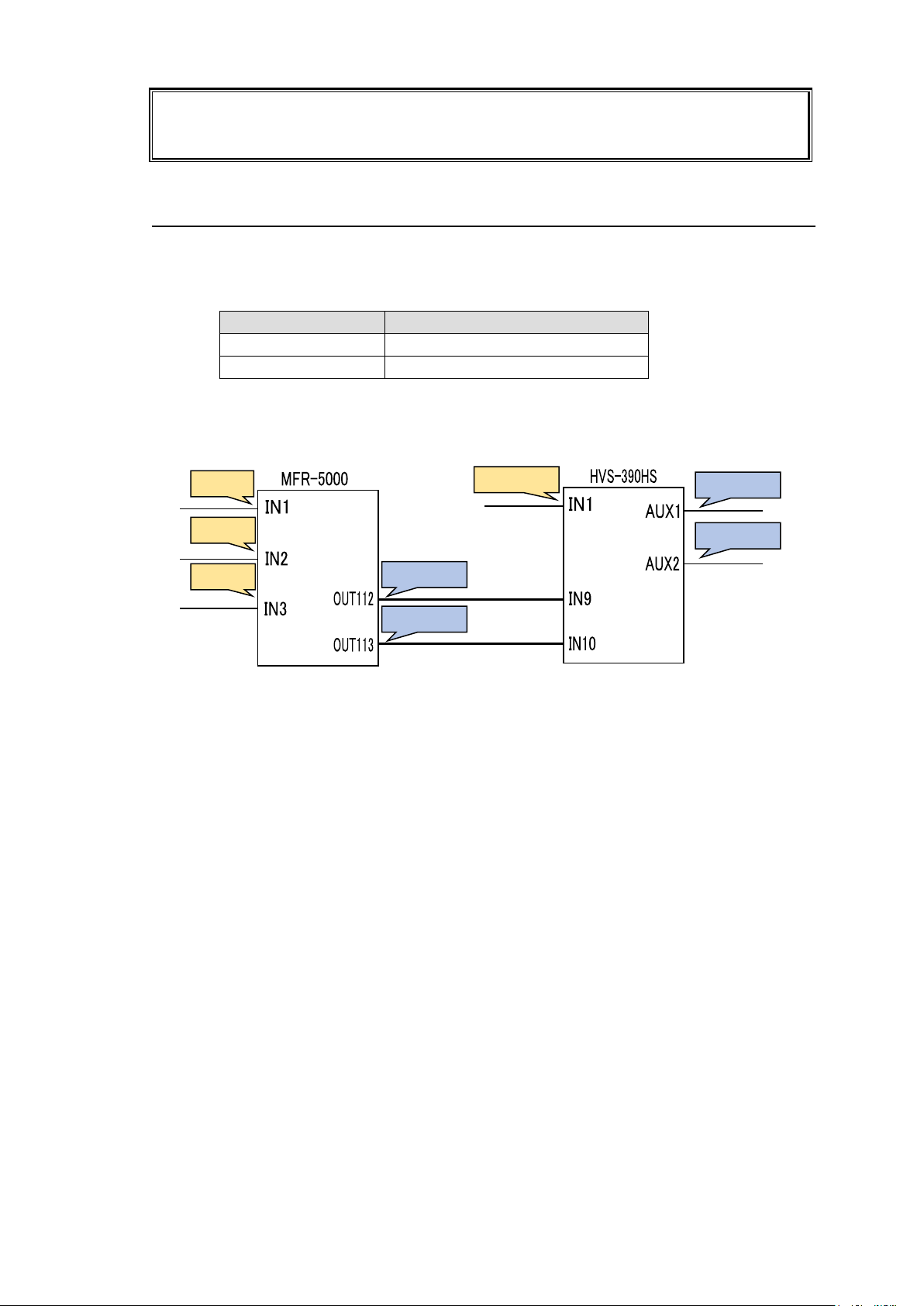
If input channels that are not assigned in the Source Assignment page are selected on
the switcher, they are replaced with the Alternative Source set in the Source Assignment
page in the MFR system.
Output
Input
MFR Dst 112
HVS-390HS IN9 > AUX 1
MFR Dst 113
HVS-390HS IN10 > AUX 2
DST113
SRC1
SRC2
SRC3
DST129
SRC129
DST130
DST112
3-4-2. Synchronous Crosspoints Switching
Configure the system as described 1) to 3) in Sec. 3-4-1.
4) Configure channel link settings:
Open the Re-Entry page and set the menu page as shown below.
* Physical destination channels must be assigned to these logical destination channels
on the MFR-5000.
5) Assign logical source and destination channels on the MFR-5000 to input channels and
AUX buses on the switcher.
<AUX bus assignments>
a) Open the Destination Assignment page.
b) Select HVS(AUX) under Select Table.
c) Set Level to 1.
d) Assign AUX1 to DST 129.
e) Assign AUX2 to DST 130.
<Input channel assignments>
a) Open the Source Assignment page.
b) Select HVS(AUX) under Select Table.
c) Set Level to 1.
d) Assign IN1 to SRC 129.
After above setup settings are complete:
If SRC 129 is selected for DST 129 on the MFR-5000,
IN1 is selected for AUX1 on the switcher.
If SRC 3 is selected for DST 129 on the MFR-5000,
IN9 is selected for AUX1 on the switcher and SRC 3 is also selected for DST 112 on the
MFR-5000.
If IN9 is selected for AUX1 on the switcher,
a source assigned to DST 112 is selected for DST 129 on the MFR-5000
If IN10 is selected for AUX2 on the switcher,
a source assigned to DST 113 is selected for DST 130 on the MFR-5000
58
Page 59

IMPORTANT
-Note that destination channels to which physical channels are assigned (DST 112
and DST 113 in the example above) on the MFR-5000 cannot select source channels
to which the switcher input channels are assigned (SRC 129 in the example above).
-If an AUX crosspoint is switched on the switcher by the Synchronous Crosspoints
switching and it is not listed in Re-Entry page, the AUX crosspoint returns to the
previous state.
59
Page 60
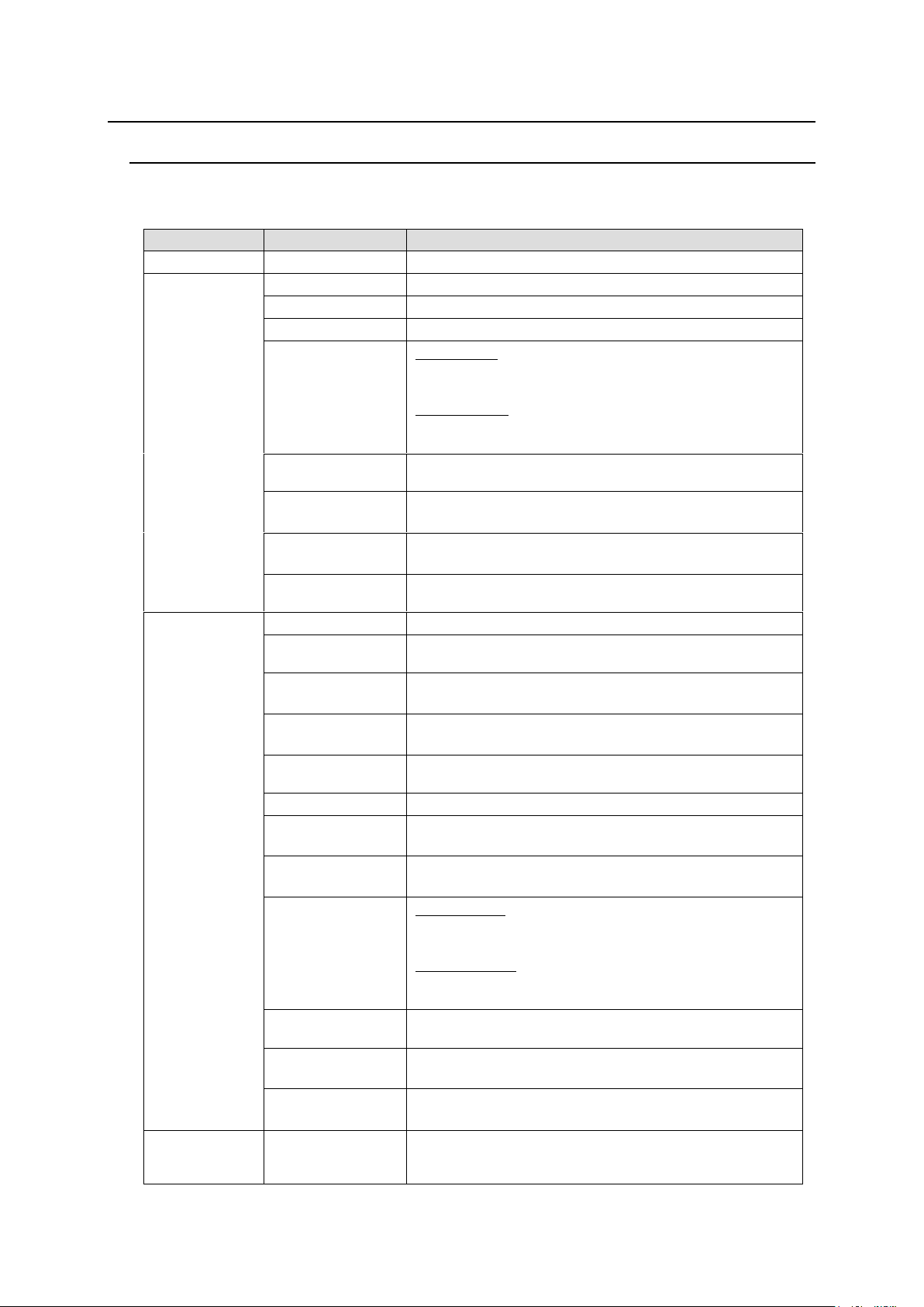
4. Settings via MFR-5000 Menus
Function
Indication
Description
MENU EXIT
MENU EXIT
Exits the menu.
ALARM
AC
Displays the AC alarm. (OK: Normal / NG: Alarm)
DC
Displays the DC alarm. (OK: Normal / NG: Alarm)
TEMP
Monitors the temperature (OK: Normal / NG: Alarm)
FAN
ALARM PS:
Displays the fan alarm for the power supply unit.
(OK: Normal / NG: Alarm)
ALARM FAN:
Displays the fan alarm for the main unit. (NORMAL /
WARNING / ERROR)
FAIL
Displays the overheat alarm for the power supply unit.
(OK: Running / NG: Stopped)
V1, V2, …
Displays an alarm for the each card voltage
(OK: Normal / NG: Alarm)
CPU2COND
Displays the Secondary CPU condition
(OK: Normal / NG: Alarm)
CNFG
Displays the CPU and MTX card startup status.
(OK: Startup successful / NG: Startup error)
STATUS
CPU1/2FIRM
Displays firmware versions
CPU1/2FPGA
MTX FPGA
Displays FPGA versions (CPU cards / MTX cards)
PS
Displays whether the power supply unit is present.
(INSTALLED: Present / NONE: Absent)
CPU
Displays whether the CPU card is present.
(INSTALLED: Present / NONE: Absent)
SLOT
Displays whether an input or output card is present in
each slot. (INSTALLED: Present / NONE: Absent)
TEMP
Monitors the temperature (°C)
AC
Displays the input voltage of the power supply unit
(OK: Normal / NG: Alarm)
DC
Displays the output voltage of the power supply unit
(OK: Normal / NG: Alarm)
FAN
PS STATUS:
Displays the fan alarm for the power supply unit.
(OK: Normal / NG: Alarm)
FAN STATUS:
Displays the fan alarm for the main unit. (NORMAL /
WARNING / ERROR)
FAIL
Displays the overheating alarm for the power supply
unit. (OK: Running / NG: Stopped)
V1, V2, …
Displays an alarm for the each card voltage
(OK: Normal / NG: Alarm)
CPU2COND
Displays the Secondary CPU condition
(OK: Normal / NG: Alarm)
SETTINGS
-
Allows you to change the Ethernet, menu display
brightness, and reference signal settings, and shut
down slots. See section 4-5. “SETTINGS”
4-1. Function List
The MFR-5000 front menu display allows you to change or verify settings as shown below.
* The status and alarm display for uninstalled functions will be indicated as “- -“.
60
Page 61
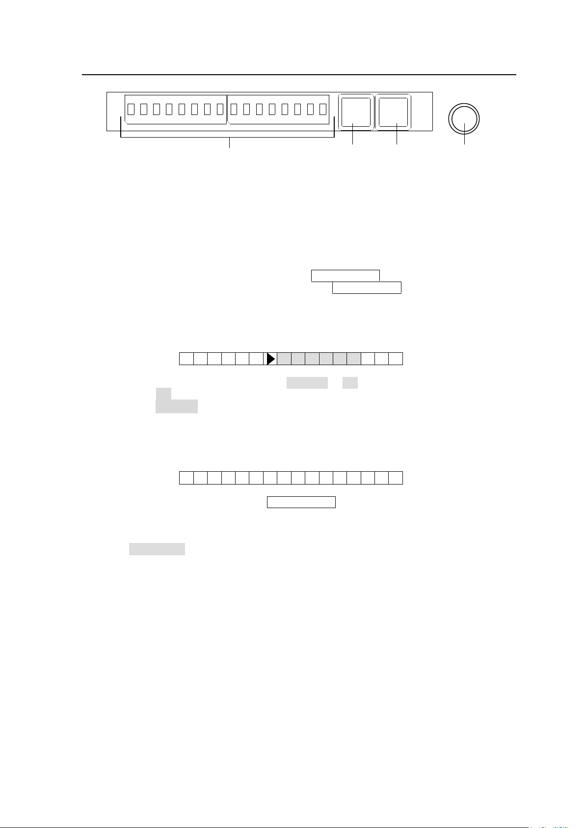
4-2. Front Menu Basic Operation
A G R E E ? C A N C E L | O
K
D A T A S E T D O N E !
1
2345678
1
2345678
ALARM
ACTIVE/BUSY
CONTROL knob
Menu display
1. Activate the menu display
Hold down the CONTROL knob for at least 3 seconds.
2. Select a menu item
Turn the CONTROL knob to select a menu item. Press the CONTROL knob after selecting an
item to go to the lower menu level.
* When multiple setting items are shown at the same time
Repeat the above for the items one by one from the left. (The subject item blinks.)
To return to the previous item, press the ACTIVE/BUSY button.
(To return to the above menu level, press the ACTIVE/BUSY button while the leftmost
item is blinking.)
3. Confirmation display
The confirmation display menu appears as shown below.
Turn the CONTROL knob to select either CANCEL or OK.
→ Select OK, and press the CONTROL knob to confirm the setting.
→ Select CANCEL, and press the CONTROL knob to cancel the setting and return to the
settings display.
4. Setting completion
The menu display appears as shown below.
Press either the CONTROL knob or ACTIVE/BUSY button while the menu is displayed as
above to return to the above menu level.
5. Exit the menu
Select MENU EXIT, and press the CONTROL knob to exit the menu.
61
Page 62
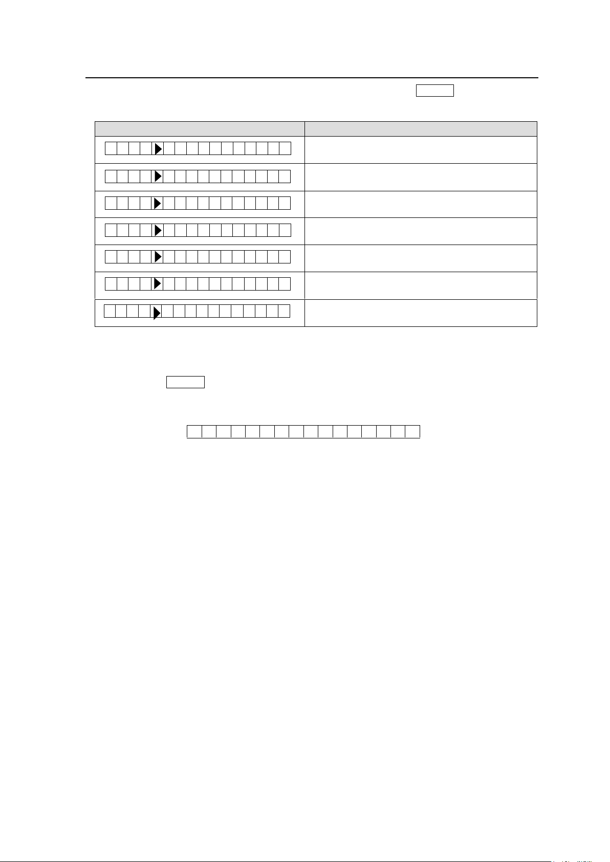
4-3. Blinking ALARM Button
Indication
Description
Displays the number of power supply units that
have an alarm triggered.
Displays the number of fans that have an alarm
triggered.
Displays the number of CPU cards that have an
alarm triggered.
Displays the number of MTX cards that have an
alarm triggered.
Displays the number of REAR cards that have an
alarm triggered.
Displays the number of alarms in each slot.
Displays the number of CPU or MTX cards that
have a configuration alarm triggered.
O P E R A T I O N N O R M A
L
P S 1 A L M F A N 1 A L M C P U 1 A L M M T X 1 A L M R E A R 1 A L M S L O T 1 A L M C N F G 1 A L M
Alarm buttons blink to indicate alarms as shown below. Press the ALARM button while the
buttons are blinking to see simplified alarm information.
* To see alarm information details, press the CONTROL knob while the above indications are
being displayed. (The Alarm menu will be displayed.)
* Pressing the ALARM button when no alarm is triggered, the menu display will appear as
shown below and return to the previous display.
62
Page 63
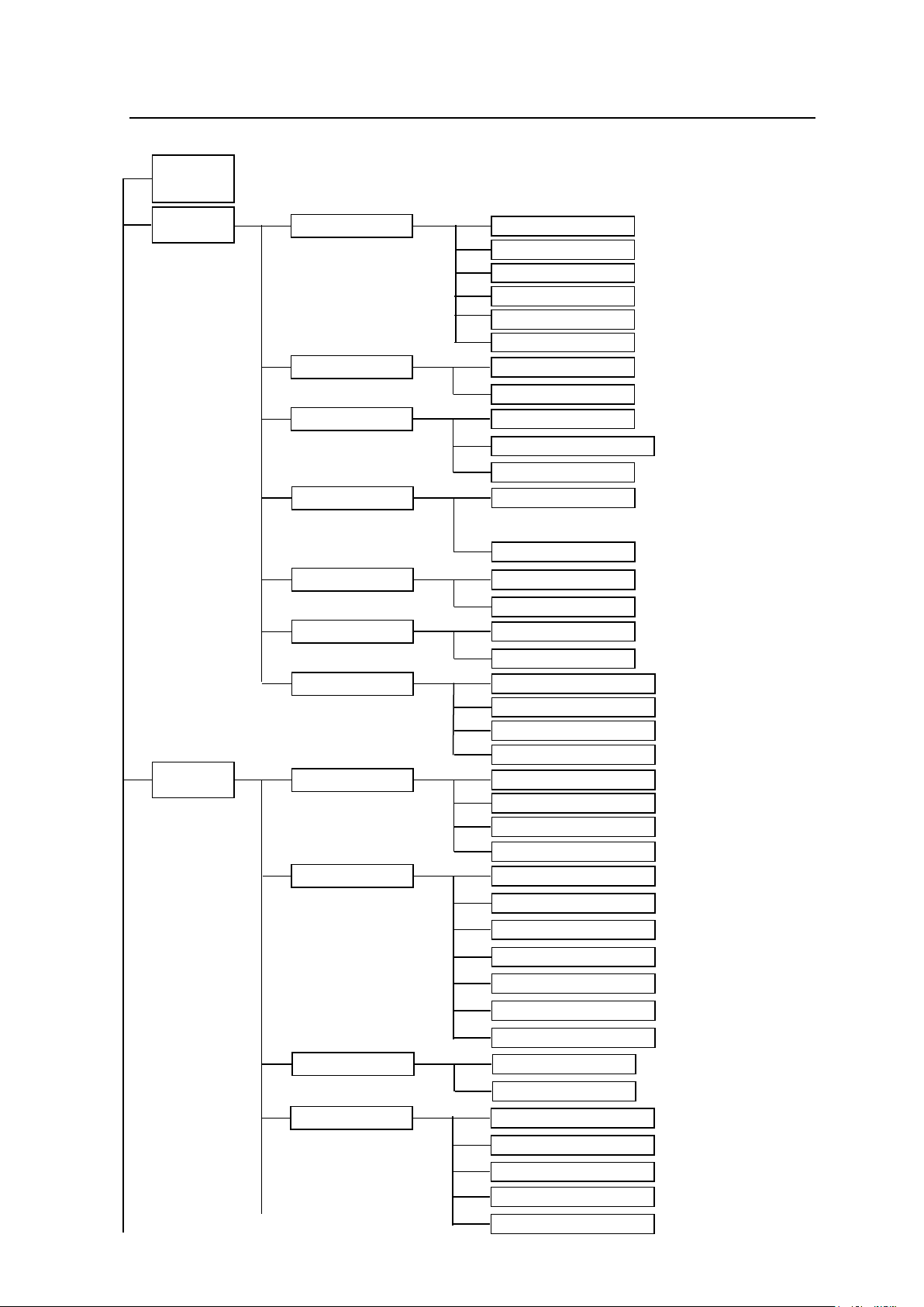
4-4. Menu Structure
ALM ► PS* ► FAIL
ALM ► PS* ► AC
ALM ► PS* ► DC
ALM ► PS* ► TEMP
(Exiting menu)
ALARM : PS EXIT
STATUS
ALARM
MENU
EXIT
ALARM PS
ALM ► PS* ► FAN
ALARM FAN
ALM ► FAN*
(Exiting menu)
ALARM : FAN EXIT
ALARM CPU
ALM ► CPU* ► V*
(Exiting menu)
ALARM : CPU EXIT
ALM ► CPU2 ► COND
ALARM REAR
ALM ► REAR ► V*
(Exiting menu)
ALARM : REAR EXIT
ALARM SLOT
ALM ► SLT* ► V*
(Exiting menu)
ALARM : SLOT EXIT
ALM ► CNFG ► MTX
ALARM CNFG
ALM ► CNFG ► F/W*
ALM ► CNFG ► CPU*
(Exiting menu)
ALARM : CNFG EXIT
PS* ► FAN
PS* ► FAIL
(Exiting menu)
STATUS : PS EXIT
PS* ► DC
PS* ►
PS* ► AC
PS* ► TEMP
PS STATUS
FAN STATUS
FAN* ►
(Exiting menu)
ALARM : FAN EXIT
MTX FPGA ►
CPU* FIRM ►
VERSION
CPU* FPGA ►
(Exiting menu)
STATUS : VER EXIT
CPU* ► TEMP
(Exiting menu)
STATUS : CPU EXIT
CPU* ► V*
CPU* ►
CPU2 ► COND
CPU STATUS
(Continues to next page)
ALARM MTX
ALM ► MTX ► V*
(Exiting menu)
ALARM : MTX EXIT
If CPU Card is Active:
63
Page 64
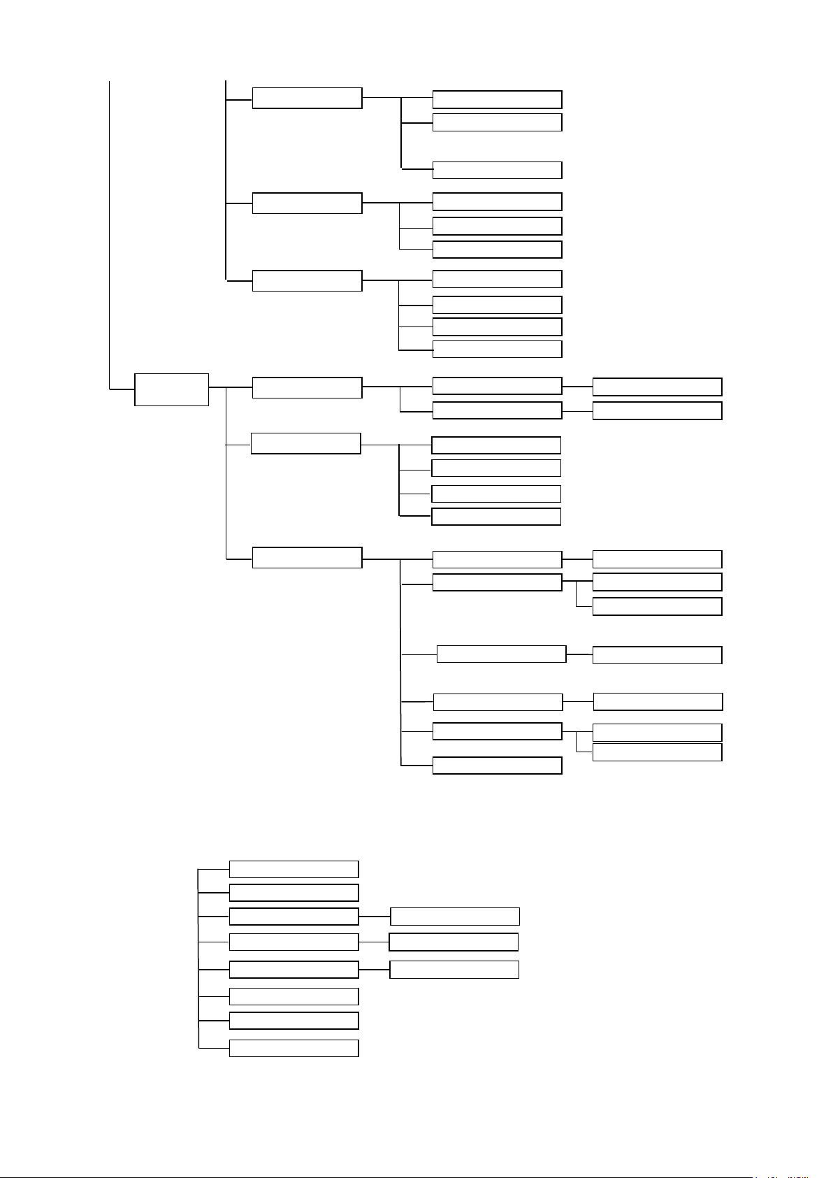
CPU REDUNDANT
IP ADDR[PC-LAN]
NETMASK[PC-LAN]
MENU EXIT
GATEWAY[PC-LAN]
NET MASK
MASK ►
IP ADDRESS
IP ►
MENU BRIGHTNESS
BRIGHT ►
MTX STATUS
REAR STATUS
SLOT STATUS
MFR-LAN
MU SETTING
(Exiting menu)
(Exiting menu)
(Exiting menu)
SLOT* ► V*
SLOT* ►
SLOT* ► TEMP
STATUS : SLOT
SETTINGS
MTX ► TEMP
STATUS : MTX EXIT
MTX ► V*
REAR ► V*
REAR ► TEMP*
STATUS:REAR EXIT
IP ►
MASK ►
BRIGHT►
REF ►
REF ►
IP ADDRESS
NET MASK
MENU BRIGHTNESS
REFERENCE
FORMAT
SLOT ► *
SLOT ► * ►
SHUT DOWN
CPU REDUNDANT
FMT ►
PS2 ►
PS2 INSTALL
PC-LAN
IP ADDRESS INFO
NET MASK INFO
GATEWAY INFO
PC-LAN REBOOT
If CPU Card is not Active:
64
Page 65
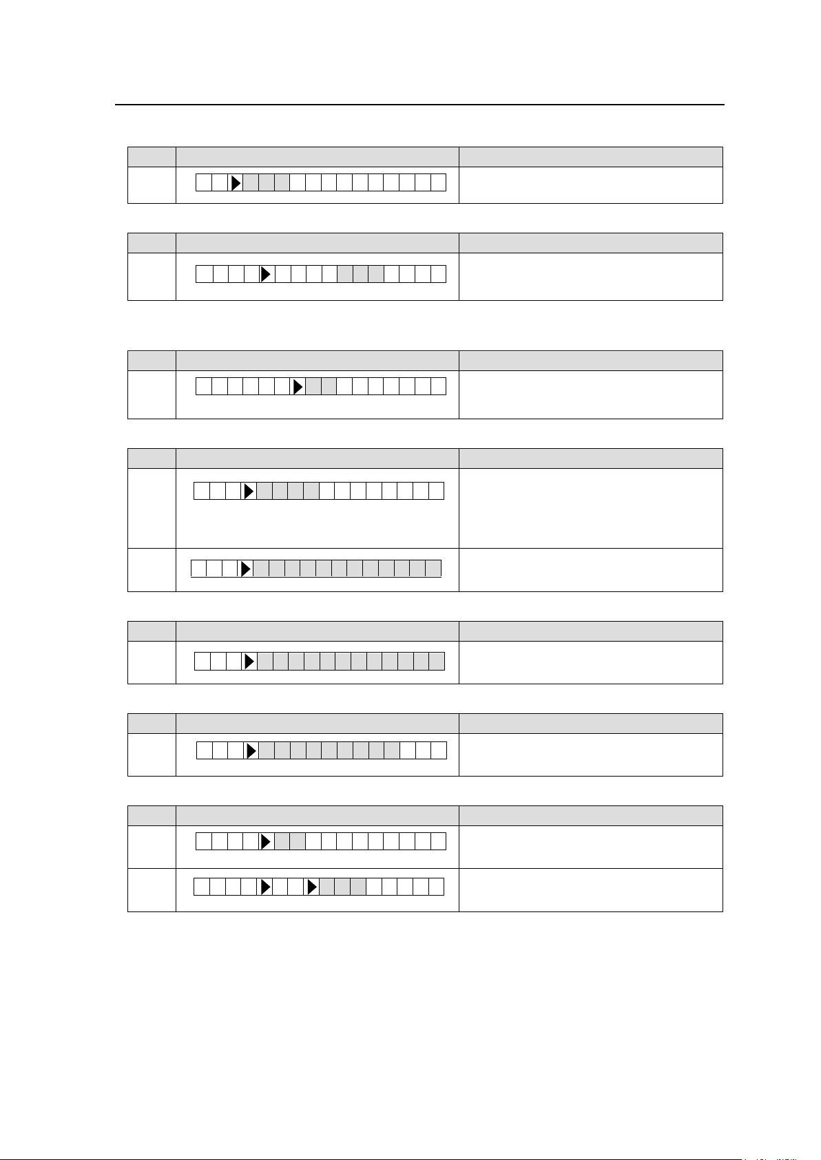
4-5. SETTINGS
Step
Display
Description
1
Allows you to set the IP address.
(For MFR-LAN/LAN (TO RU) connection)
Step
Display
Description
1
Allows you to set the subnet mask.
(255.0.0.0 to 255.255.255.254)
(For MFR-LAN/LAN (TO RU) connection)
Step
Display
Description
1
Allows you to set the menu display
brightness.
brightness: 1 (dark) to 15 (bright)
Step
Display
Description
1
Allows you to select how to select a
reference signal format.
AUTO: Automatic detection
MANUAL: Manual selection
If set to MANUAL, select a signal below.
2
Allows you to select a reference signal
from BB or TRI-SYNC.
Step
Display
Description
1 Allows you to select a video format
Step
Display
Description
1
Displays whether the redundant power
supply unit is present.
Step
Display
Description
1
Allows you to select a slot to shut down.
2
Select OFF to shut down.
Select ON to supply power.
I P 1 9 2 . 1 6 8 . 0 0 1 . 0 M A S K 2 5 5 . 2 5 5 . 0 0 0 B R I G H T 0 7 S L O T 0 1 P S 2 I N S T A L L E D S L O T 0 1 O F F R E F A U T O R E F B B F M T 1 0 8 0 5 9 . 9 4 i
1. MFR-LAN
[ IP ADDRESS ]
[ NET MASK ]
2. MU SETTING
[ MENU BRIGHTNESS ]
[ REFERENCE ]
[ FORMAT ]
[ PS2 INSTALL ]
[ SHUT DOWN ]
* When selecting the following functions, the confirmation display appears. (Select OK to
execute the function.)
■CPU REDUNDANT: Manually switches CPU cards 1 and 2.
Requires time for sharing files between CPUs after startup or
CPU changeover, during which crosspoint switchings cannot
be performed.
■PC-LAN(IP ADDRESS INFO / NET MASK INFO / GATEWAY INFO):
Displays the PC-LAN port settings.
■PC-LAN REBOOT: Restarts the PC-LAN port.
65
Page 66
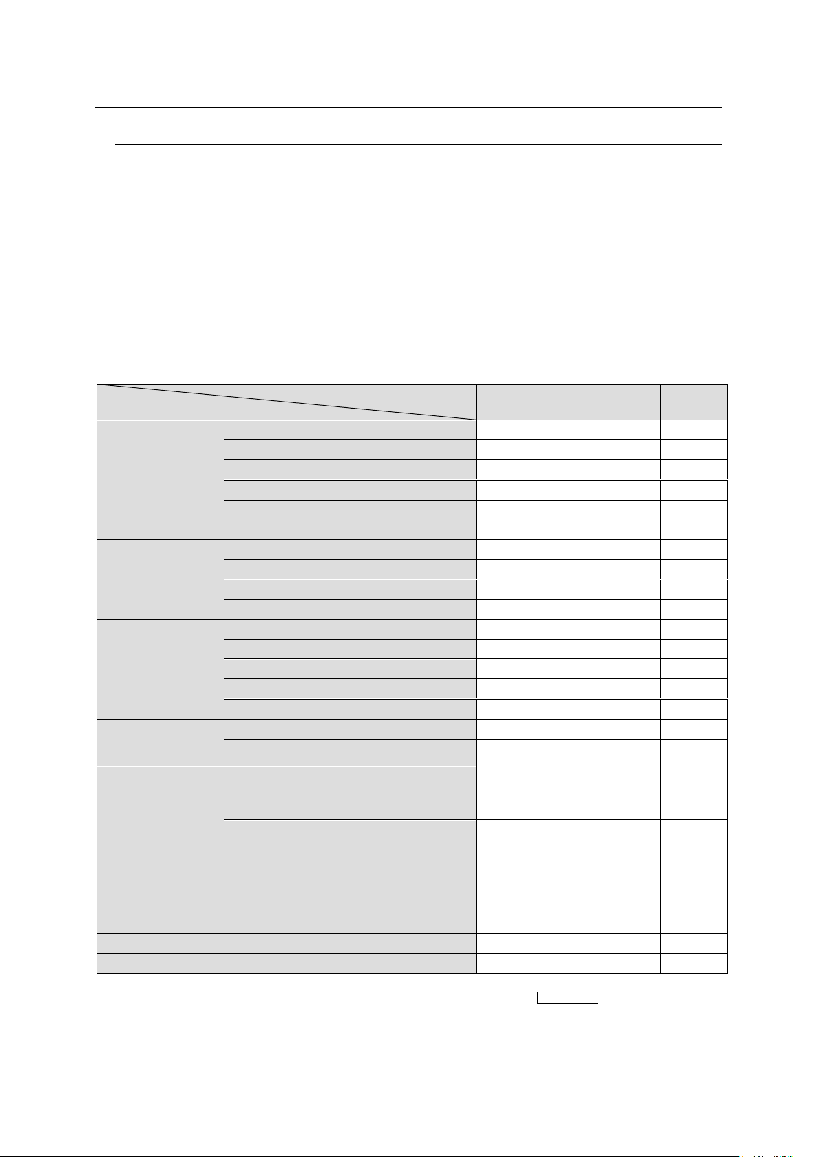
5. Remote control panel Operation
Controller
Function
Remote
Control Units
Web-based
Control
Ref.
Crosspoint
change
(1 channel)
By changing source and/or destination
○
○
6-1-1
Using bus buttons
○
---
6-1-2
Using buttons and the CONTROL knob
18, 16T
---
5-4-2
Using the display
16D
---
5-5-1
CHOP function
●
---
6-1-3
TAKE function
●
○
6-1-4
Crosspoint
change
(Simultaneous)
Main unit stored SALVO
●
▲
6-2-1
Control panel button assigned SALVO
39, ●
▲
6-2-2
TAKE function
●
○
6-2-3
LINK function
●
▲
6-2-4
Erroneous
operation
protection
LOCK LOCAL
○
---
6-3-1
LOCK OTHER/ALL
○
○
6-3-2
Crosspoint inhibit
---
○
Web
Monitor output function
(*1)
●
---
6-4
Operation Preview function
●
---
6-5
Main unit and
system setting
change
Source/destination name settings
---
○
Web
System tally settings
---
○
Web
Remote control
setting change
Mode menu
39, 18, 16T
---
5-4-2
Button assignment
39, 18, 16T
(*2)
16D
○
5-4-3-12
(5-4-2)
PAGE function
○
---
5-2-2
Group setting
---
○
5-2-2-1
Multi-remote control panel operation
39
(*3)
▲
5-11-2
IP address setting
▲
▲
5-6-1
Other settings
39
○
5-4-3
5-6
Status display
●
●
---
Alarm indication
●
●
---
5-1. Functions and Operations
The below table shows the functions that can be controlled using the remote control panel (RU)
and/or Web-based Control (GUI).
* For details on Web-based Control operation, see the separate MFR SERIES Web-based
Control Operation Manual.
Description on Control
○: Changing settings and execution are both supported
●: Execution is supported
▲: Changing settings is supported
39: Supported by the MFR-39RU, MFR-39RUA
18: Supported by the MFR-18RU, MFR-18RUA
16D: Supported by the MFR-16RUD
16T: Supported by the MFR-16RUTA
*1 This function is supported only for the MFR-5000.
*2 Source and destination button/channel assignments can be performed using CONTROL on MFR-18RU/
16RUTA/18RUA/39RUA units.
*3 MFR-39RU/39RUA can change multi-remote control panel operation settings while other remote control panels
can only be used for operation.
66
Page 67

5-2. Basic Operation on Control Panels
This section describes basic operation of the remote control panel and how to set and execute
various functions.
5-2-1. Buttons
1) Assign functions to buttons (change assignments)
To use buttons on the remote control panel, assign functions to the buttons in the Web-based
Control: Assign Function page]. Any function can be assigned to any button except the
CANCEL, PAGE A, PAGE B, UP, DOWN and ENTER buttons.
Button Assign Procedure
(1) In the Web-based Control, click to open the menu tree at the left side. Click to select
Assign Function to display the menu page.
(2) Set the page, button and function respectively to assign functions to buttons. Buttons can
be selected by specifying Button IDs or clicking on button icons.
(3) After selecting a function, set the function specific settings.
(4) After all settings are completed, click Send to apply the settings.
The MFR-39RU menu display can also assign functions.
► See section 5-4-3-12 “BTN ASSIGN”
The MFR-39RUA menu display can also assign functions.
► See section 5-4-4-4 “BUTTON ASSIGN”
Source and destination button/channel assignments can be performed using the control
knob on MFR-18RU/ 16RUTA/18RUA / 39RUA units.
► See section 5-2-3. “Control Knob”
MFR-16RUD can perform assignments using the display on the front panel.
► See section 5-5-2 “Changing Button Assignments” for details
2) Press buttons to execute functions
Press a button to execute the assigned function. The button LED indication, NAME
DISPLAY, and MENU display change according to the assigned function.
67
Page 68
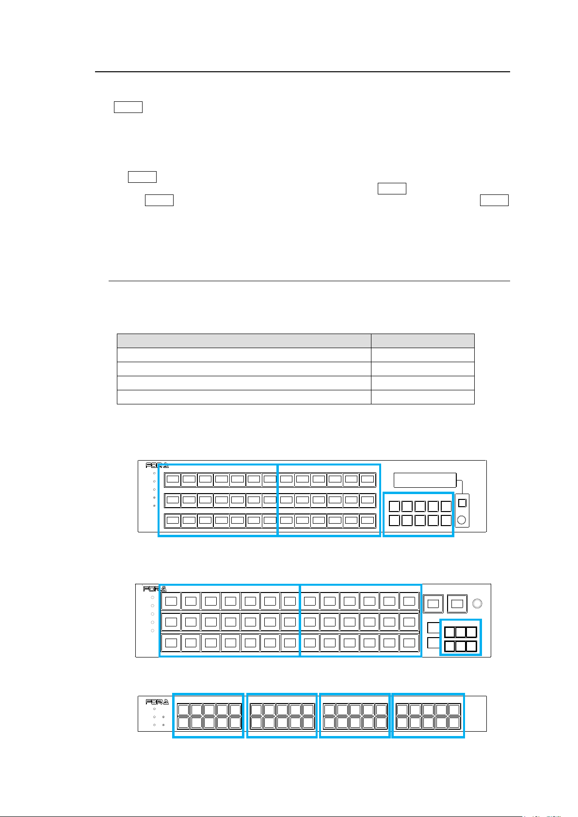
5-2-2. Page Function
Remote Control Unit
Button group
MFR-16RU/16RUD
A to B
MFR-16RUW/32RUW
A to C
MFR-39RU/40RU/18RU/16RUTA/39RUA/18RUA
A to D
MFR-64RUW
A to E
RESET
CANCEL
MFR-39RU
REMOTE CONTROL UNIT
POWER
BUSY
LOCK
SETUP
Group A
Group B
Group C
POWER
BUSY SETUP
LOCK R ESET
MFR-40RU
REMOTE CONTROL UNIT
Group A
Group B
Group C
Group D
POWER
BUSY
LOCK
SETUP
RESET
DEST SRC
A
B
C
D
PAGE
MFR-39RUA
REMOTE COMTROL UNIT
Group A
Group B
Group C
By managing a set of remote control panel front panel buttons as a page, page-assigned
functions can be performed by a single button press. Pages can be changed either by using
the PAGE button (see section 5-3 “Function Buttons”) or the control knob by changing the
Mode. (See section 5-4 “MODE Button and Mode Menu.")
There also are settings for the Page function in the Mode and Setting menus. Please also
refer to the following sections.
For PAGE button assignment: 5-4-3-5 “PAGE ASSIGN”
This section describes the setting for whether to assign the PAGE button in all pages.
Having PAGE buttons assigned to all pages helps you not to have to look for the PAGE
button.
For Mode menu settings: 5-4-3-4 “PAGE MODE”
This section describes how to select pages using the control knob.
5-2-2-1. Group Page Changes
Pages can be changed per a button group. The number of available button groups differ
depending on a remote control unit as shown in the table below. These groupings can be
freely changed using the Web-based Control menu.
Default button groups of control panels are determined as shown in the figures below.
MFR-39RU
MFR-39RUA
MFR-40RU
68
Page 69
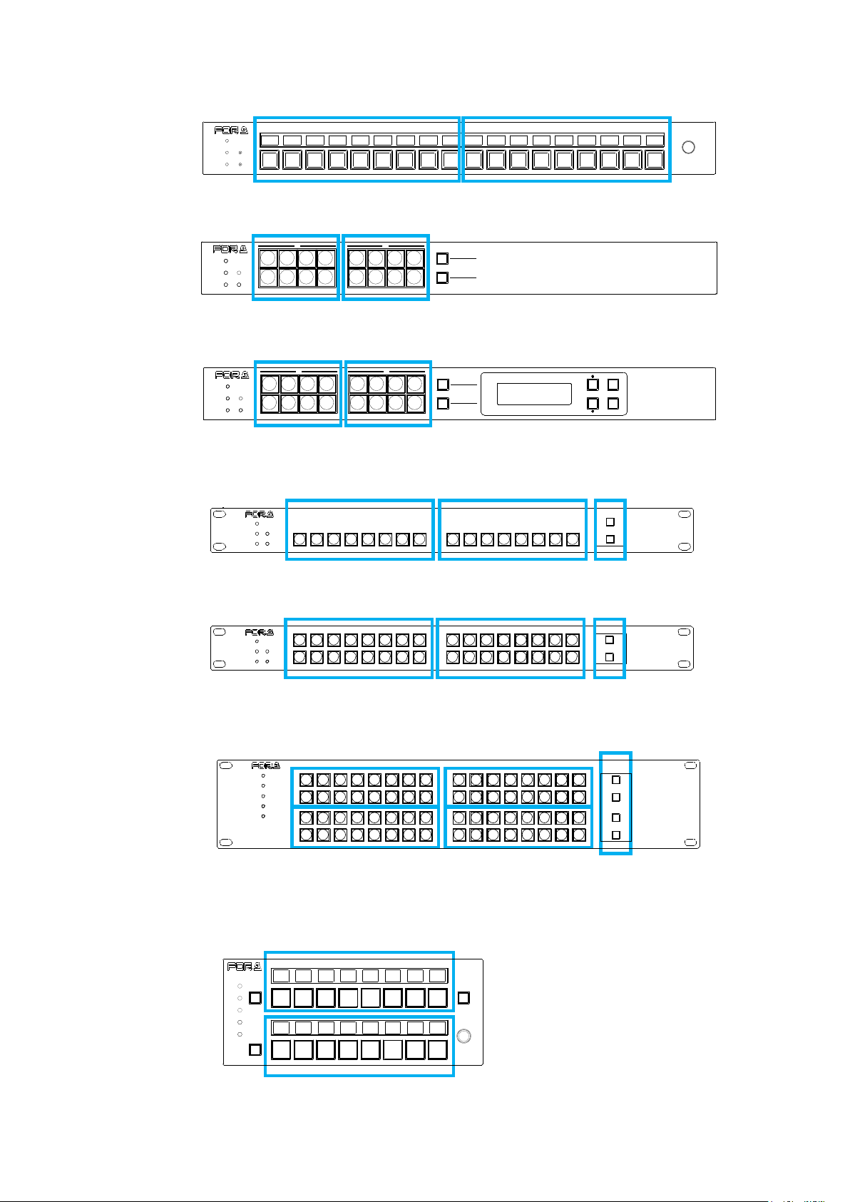
PAGE A
(HOLD 3SEC)
PAGE B
LOCK RESET
POWER
BUSY SETUP
LOCK DEST
(HOLD 3SEC)
LOCK PANL
A B
REMOTE CONTROL UNIT
MFR-16RU
Group A
Group B
POWER
BUSY SETUP
LOCK RESET
MFR-18RU
REMOTE CONTROL UNIT
Group A
Group B
PAGE A
(HOLD 3SEC )
PAGE B
LOCK RESET
POWER
BUSY SETUP
LOCK DEST
(HOLD 3SEC )
LOCK PANL
CANCEL
ENTER
A B
MFR-16RUD
REMOTE CONTROL UNIT
Group A
Group B
POWER
BUSY SETUP
LOCK RESET
MFR-16RUW
FUNCTION
1
2
REMOTE CONT ROL UNIT
Group C
Group A
Group B
POWER
BUSY SETUP
LOCK RESET
FUNCTION
1
2
REMOTE CONTROL UNIT
MFR-32RUW
Group A
Group B
Group C
Group C
Group D
Group E
Group A
Group B
MFR-64RUWREMOTE CONTROL UNIT
1
2
1
2
POWER
BUSY
LOCK
SETUP
RESET
FUNCTION
Group A
Group B
MFR-16RUTA
REMOTE CONTROL UNIT
LOCK
POWER
BUSY
PAGE A
LOCK
SETUP
RESET
PAGE B
MFR-18RU/18RUA
MFR-16RU
MFR-16RUD
MFR-16RUW
MFR-32RUW
MFR-64RUW
MFR-16RUTA
69
Page 70
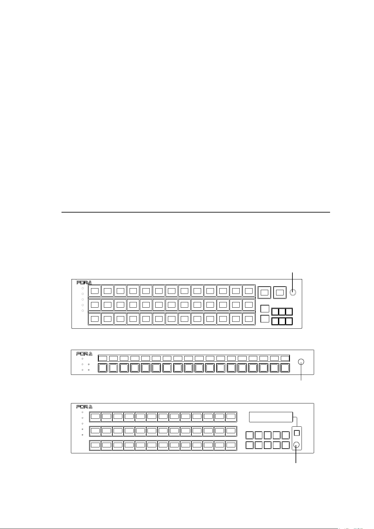
Page Limit and Maximum Page Number Setting
POWER
BUSY
LOCK
SETUP
RESET
DEST SRC
A
B
C
D
PAGE
MFR-39RUA
REMOTE COMTROL UNIT
RESET
CANCEL
MFR-39RU
REMOTE CONTROL UNIT
POWER
BUSY
LOCK
SETUP
CONTROL
POWER
BUSY SETUP
LOCK RESET
MFR-18RU
REMOTE CONTROL UNIT
CONTROL
CONTROL
- The maximum number of assignable pages (page limit) is:
32 for MFR-39RUA/18RUA/39RU /40RU /18RU / 16RUW / 32RUW / 64RUW / 16RUTA
2 for MFR-16RU/16RUD
- The maximum number of pages, within which the page can be changed by the Mode menu
or Page buttons, can be set within the page limit (excluding MFR-16RU/16RUD).
- The maximum page number setting is shared by all groups.
- Any page assignments or jumps are possible, but have no effect if they exceed the page
limit. ("x" will appear instead of buttons on the MFR-39RUA/18RUA/39RU/18RU/16RUTA
units.)
- The maximum page number can be set under Page-Max number in the [Web-based
Control: RU Settings page]. A warning dialog box will appear when the number is reduced
and sent.
- If the page limit is set to a number less than the displayed page, the displayed page will
automatically change to the page number limit.
5-2-3. Control Knob
If your MFR Remote control panel has a control knob, you can select destination channels or
other items using the knob.
You can also select menu items by turning and pressing the knob to confirm the selection.
Using the control knob, it is easy to select items to be displayed or to change settings by
changing modes in the Mode menu. See section 5-4 “MODE Button and Mode Menu.”
MFR-39RUA
MFR-18RU/18RUA
MFR-39RU
70
Page 71
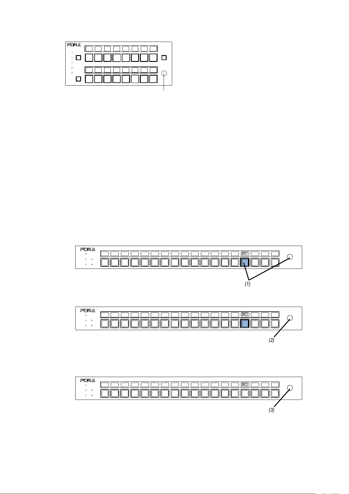
MFR-16RUTA
POWER
BUSY SETUP
LOCK RESET
MFR-18RU
REMOTE CONTROL UNIT
POWER
BUSY SETUP
LOCK RESET
MFR-18RU
REMOTE CONTROL UNIT
POWER
BUSY SETUP
LOCK RESET
MFR-18RU
REMOTE CONTROL UNIT
MFR-16RUTA
REMOTE CONTROL UNIT
LOCK
POWER
BUSY
PAGE A
LOCK
SETUP
RESET
PAGE B
CONTROL
* The Control knob can be disabled or enabled in the [Web-based Control: RU Settings
page]
Selecting a source or non-function button on MFR-18RU/16RUTA/39RUA/18RUA units
allows you to change the source channel assignment.
Selecting a destination button allows you to perform one of the following three operations set
in the RU Settings page. (MFR-39RUA units perform Assign operations.)
Assign (default): Allows you to change the channel assignment of the selected
destination button.
Crosspoint: Allows you to change the crosspoint assignment of the selected destination
button.
Disable: The operation is disabled.
The operation procedure is as follows:
(1) Press the desired source, destination or non-function button while holding down the
control knob. The button light sequentially changes its color from red to orange, then
green.
(2) Turn the control knob to select a source channel to assign to the button.
(3) Press the control knob to confirm the change. To cancel the change, press the
selected source button. After confirming or canceling the change, the button light
returns to the previous state.
71
Page 72
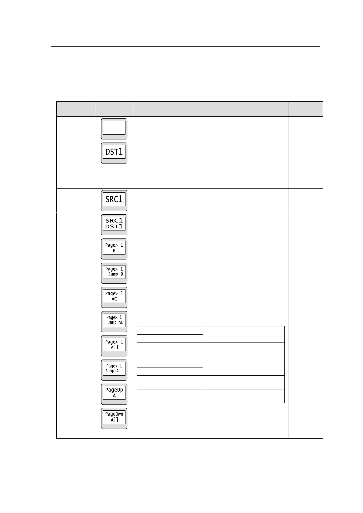
5-3. Function Buttons
Function
Button
indication
Description
Reference
None
No function is assigned.
Destination
Allows you to change a destination to the destination
specifically assigned to the button.
If locked, the button lights up with a color indicating
LOCK OTHER or LOCK ALL, which can be set in the
[Web-based Control: RU Settings page].
Re-pressing the button allows you to display the Unit ID
that locks the destination button.
6-1-1
Source
Allows you to change a source to the source specifically
assigned to the button.
6-1-1
Bus
Allows you to change a source to the source specifically
assigned to the button for a destination of the
source-destination assignment of the button.
6-1-2
PAGE
Allows you to change pages to be displayed to a
specific, next or previous page.
There is a menu that allows you to select whether to
return to the previously displayed page or to display the
next specified page.
Target group(s) is/are displayed on the bottom of the
button indication.
See Sec. 5-2-2. “Page Function” and Appendix: “How
to use Page buttons” for details on Page button setting
and operation.
Button indications (from the top to the bottom)
PAGE JUMP (single)
Switches the page to 1 for
Group B.
PAGE JUMP (single)
(*1)
PAGE JUMP (multi)
Switches the page to 1 for
Group A and C.
PAGE JUMP (multi)
(*1)
PAGE JUMP (all)
Switches the page to 1 for all
groups.
PAGE JUMP (all)
(*1)
PAGE UP (single)
Moves the page forward by 1
for Group A.
PAGE DOWN (all)
Moves the page backward by 1
for all groups.
* A corresponding page name is displayed when
assigning PAGE JUMP on MFR-18RUA/39RUA/
16RUTA units.
(*1) MFR-18RUA/39RUA/16RUTA only
5-2-2
Functions that are assignable to Remote control panel buttons are as shown in the below table.
Normally, functions are assigned via Web-based Control ([Web-based Control: Assign
Function page]).
MFR-39RU (see section 5-4-3-12. “BTN ASSIGN”) and MFR-16RUD (see section 5-5-2. “Button
Assignment Change”) are enabled to assign functions.
72
Page 73
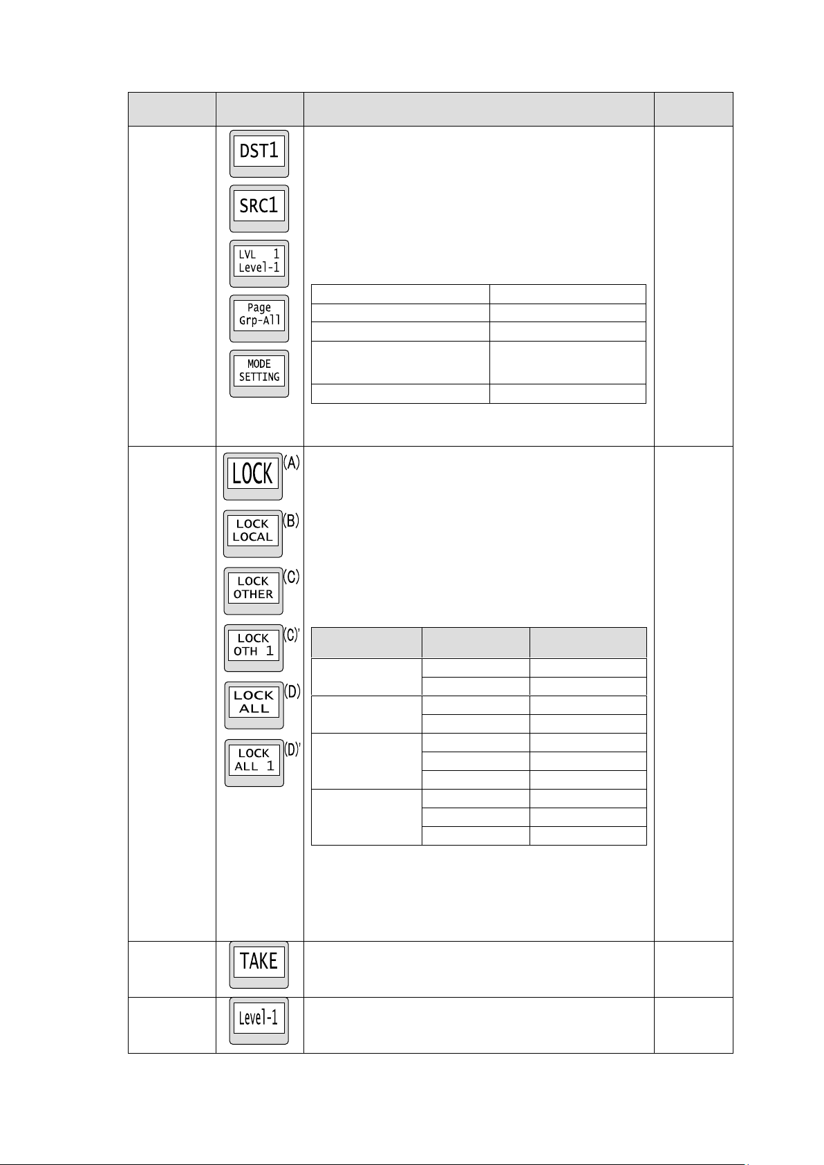
Function
Button
indication
Description
Reference
MODE
* Supported for MFR-39RU/ 18RU/ 16RUTA/ 39RUA/
18RUA.
Allows you to change mode menus.
Mode function can be assigned to either one or multiple
buttons. One button assignment allows you to change
modes one by one by every press.
To assign modes to respective buttons, select modes in
the BTN ASIGN menu.
Button indications (from the top to the bottom)
Destination mode
Source mode
Level mode
Page mode
(*1)
(PAGE_Grp-All / A / B / C / D)
* The example at left
shows the PAGE_Grp-All
mode
Setting mode
(*1)
The name set under Page Name Settings is displayed for
PAGE_Grp-A/B/C/D. (MFR-39RUA/18RUA/16RUTA
only)
5-4
LOCK
The following 4 Lock modes can be set by pressing a
button for either a short or a long time (more than 3
seconds).
-LOCK OTHER: Disables control from external devices.
-LOCK ALL: Disables all controls.
-LOCK LOCAL: Disables local control.
-NONE
Assignable 2-way button functions (short and long
press combinations) are as shown in the table below.
Assign the functions to buttons in the Web-based
Control menu.
Short press
function
Long press
function
Button indication
LOCK OTHER
NONE
(C) or (C)’ (*1)
LOCAL
(A) (*2)
LOCK ALL
NONE
(D) or (D)’ (*1)
LOCAL
(A) (*2)
LOCK LOCAL
NONE
(B)
OTHER
(A) (*2)
ALL
(A) (*2)
NONE
OTHER
(C) or (C)’ (*1)
ALL
(D) or (D)’ (*1)
LOCAL
(B)
(*1) Button indications differ depending on the current or fixed
destination.
(*2) The button indication changes if enabling either function,
for example, If a combination of LOCK OTHER (short
press) and LOCK LOCAL (long press) functions are
assigned to a button, long pressing the button changes
the indication to LOCK LOCAL.
6-3-1
6-3-2
TAKE
Allows you to enable the TAKE function for
simultaneous crosspoint changes.
6-1-4
LEVEL
Allows you to change a level to the level specifically
assigned to the button.
6-6
73
Page 74
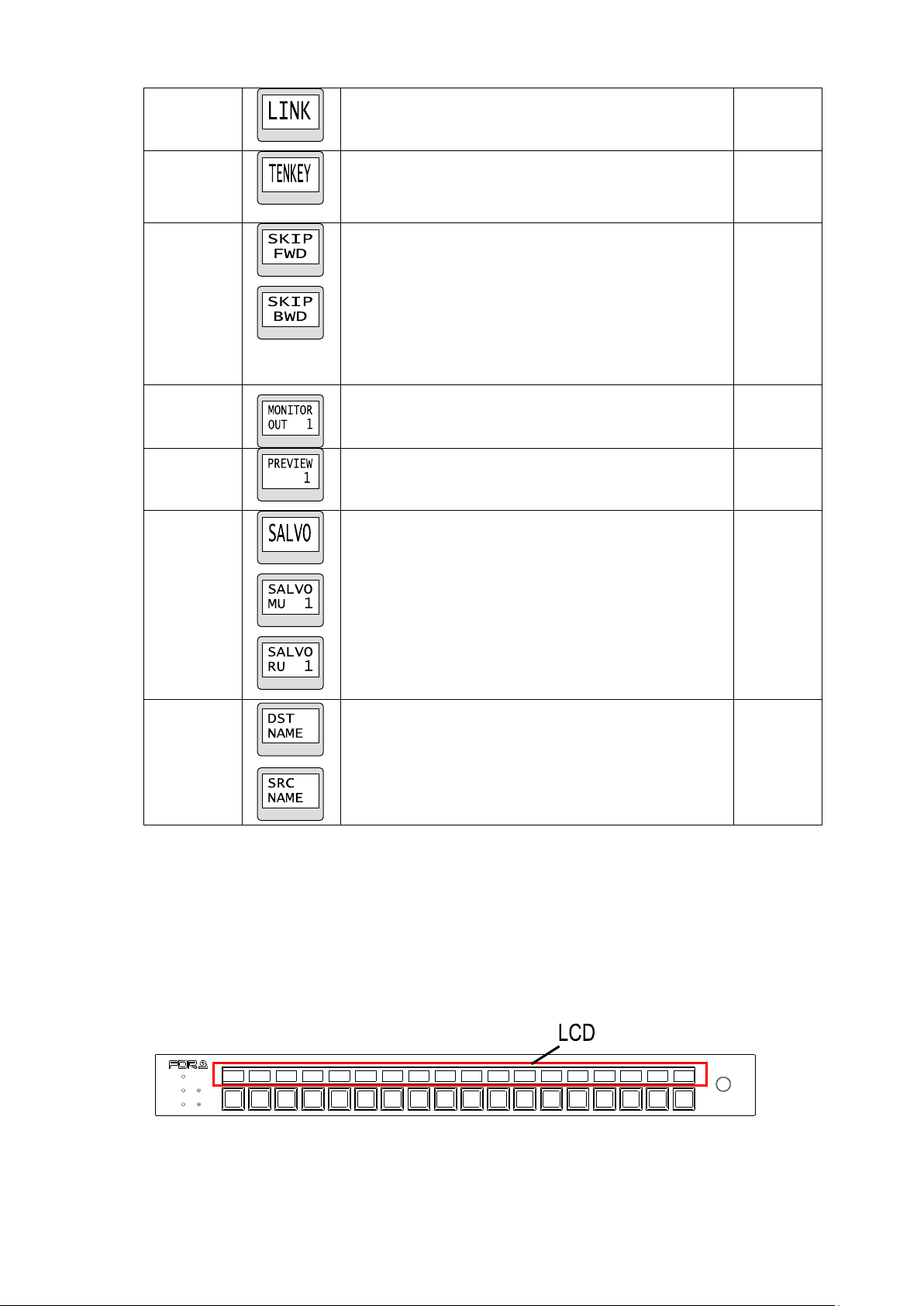
LINK
Allows you to enable or disable the LINK function.
6-2-4
TENKEY
Allows you to enable numeric keypad mode on the
remote control panel for assigning destinations and
source by their channel numbers.
* Supported only for MFR-39RU and MFR-39RUA.
6-1-1-2
SKIP
Allows you to skip the set number of destination or
source channels forward or backward to select one.
* The control knob needs to be pressed for Source
selections.
Button indications
Top: Channel number increases in the set step
Bottom: Channel number decreases in the set step
* Supported for MFR-39RU/18RU/16RUTA/
39RUA/18RUA.
6-1-1-1
Monitor Out
Allows you to enable or disable the Monitor Out
function.
* Supported only for MFR-5000.
6-4
Operation
Preview
Allows you to enable or disable the Operation Preview
function.
6-5
SALVO
Allows you to assign salvos to buttons and execute a
salvo assigned to the button or stored to a main or
remote control panel.
Button indications
Top: Salvo Store – Allows you to assign salvos to
buttons.
Middle: Salvo Recall (MU) – Executes a main
unit-stored salvo
Bottom: Salvo Recall (RU) – Executes a remote control
panel button-assigned salvo
6-2-1
6-2-2
Display
Mode
* MFR-18RU/16RUTA/18RUA only
Allows you to change button indication between
Destination and Source channel names.
<Button indication>
Top: DST NAME
Bottom: SRC NAME
Destination Button LCD Indication
POWER
BUSY SETUP
LOCK RESET
MFR-18RU
REMOTE CONTROL UNIT
Usually destination channel names are displayed on the LCD above the destination buttons.
The MFR-18RU can also display source channel names that are selected for destinations. To
display source channel names, set the menu under Display Setting in the [Web-based Control:
RU Settings page]. Note that Display Mode buttons on MFR-18RU/16RUTA units can switch
the button indication between destination and source names.
In the case of breakaway switching with multiple levels, the name of the level with the smallest
number will be displayed.
MFR-18RU/18RUA
74
Page 75
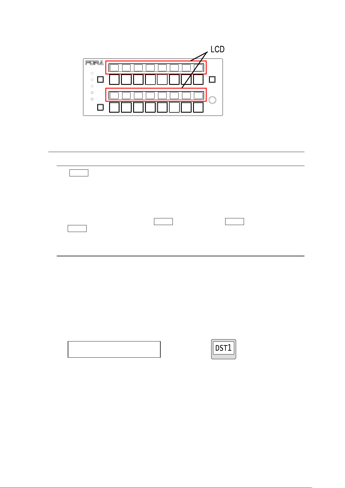
Menu display
Button LCD / Current DEST button (39RUA only)
MFR-16RUTA
REMOTE CONTROL UNIT
LOCK
POWER
BUSY
PAGE A
LOCK
SETUP
RESET
PAGE B
DST : 1 [DST1 ]
LVL : 0001 [Level-1 ]
MFR-16RUTA
5-4. MODE Button and Mode Menu
(MFR-39RU/18RU/16RUTA/39RUA/18RUA)
5-4-1. Outline
The MODE button allows you to select different setting modes. As the setting mode changes
available items on the MENU and LCD displays and for the control knob change.
(Supported only for MFR-39RU/18RU/16RUTA/39RUA/18RUA.)
Modes are selectable for assignment. Assign only necessary modes to allow for easier
searches.
Multiple buttons can be assigned to MODE buttons. If multiple MODE buttons are assigned,
the MODE button will be highlighted (the text background illuminates) when it is pressed.
5-4-2. Mode Menu
The Mode menu has 5 mode options. In Setting mode, setting options are different in the
MFR-18RU/16RUTA/39RU/39RUA and MFR-18RUA.
(The menu display and control knob setting mode are supported only for MFR-39RU.)
Destination Mode
MENU: Displays the current destination channel [name] and its level [name].
LCD: Displays the current destination channel.
Current DEST button: Displays the current destination channel. Pressing the button shift
the status display between LEVEL and LOCK.
Turning the knob: Changes the current destination channel.
75
Page 76
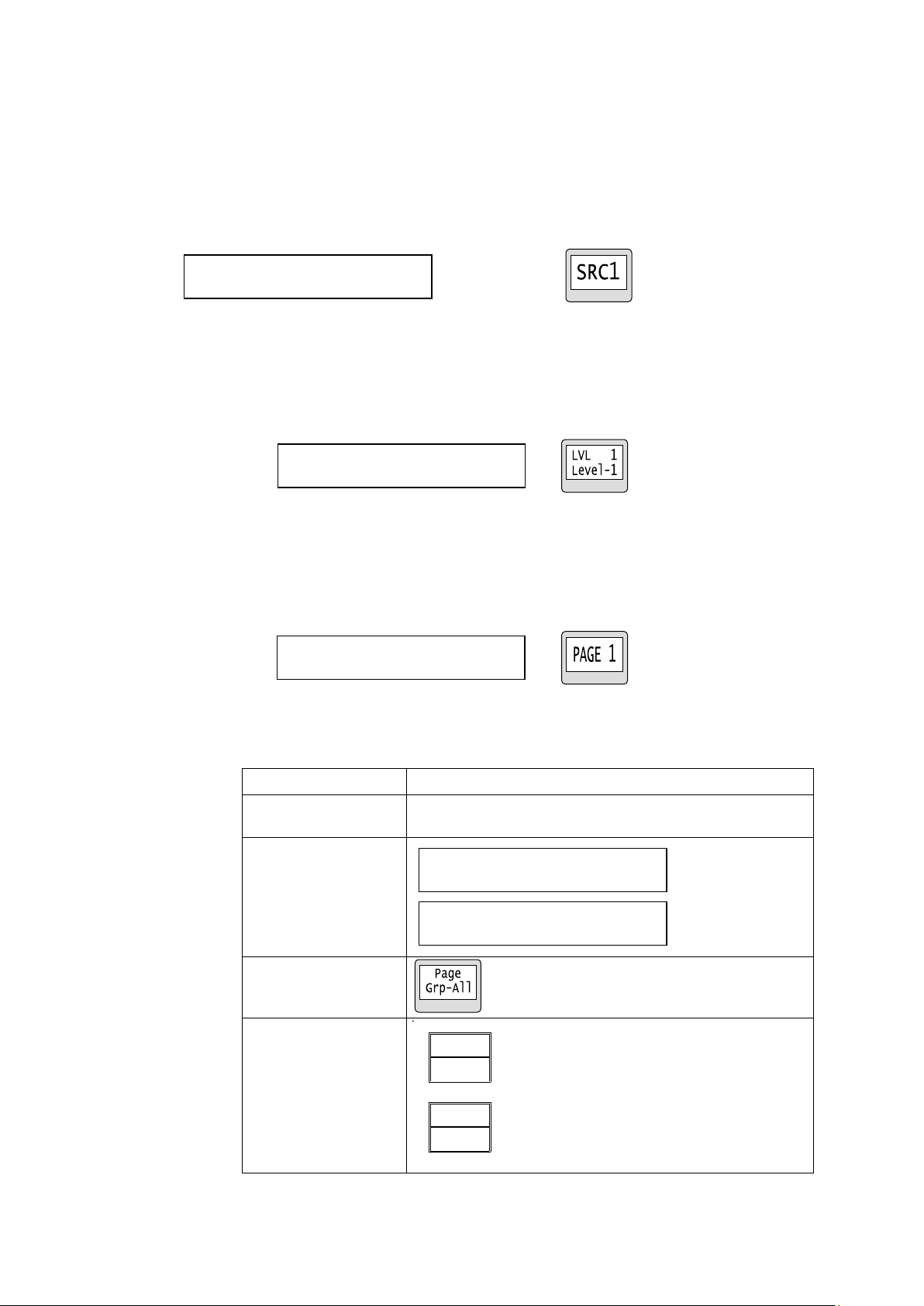
Source Mode
Menu display
Button LCD / Current SRC button (39RUA only)
PAGE JUMP
Moves the page to the specified number for all groups.
PAGE UP/DOWN
Moves the page forward or backward by the specified
number for all groups.
MENU display
LCD display
Current PAGE
display
LVL : 0001 [Level-1 ]
PAGE (UP/DOWN) : 1
PAGE (UP/DOWN)
Grp-A: 1 B: 1 C: 1 D: 1
PAGE (JUMP)
Grp-A: 1 B: 1 C: 1 D: 1
SRC : 1 [SRC1 ]
A
B
C
D
PAGE
01
01
01
01
MENU: Displays the source channel [name] for the current destination.
LCD: Displays the source channel for the current destination.
Current SRC button: Displays the source channel of the current destination channel.
Turning the knob: Changes the source channel.
Pressing the control knob applies the change.
* Press TAKE instead of the control knob when applying source changes in TAKE mode.
Level Mode
MENU: Displays the current level [name] of the remote control panel.
LCD: Displays the current level and its display on the remote control panel.
Menu display Button LCD
Page Mode
MENU: Displays the page number currently assigned to the remote control panel.
LCD: Displays the page number currently assigned to the remote control panel.
Turning the knob: Changes the page number.
Menu display Button LCD
MODE PAGE(PAGE_Grp-ALL)
76
Page 77
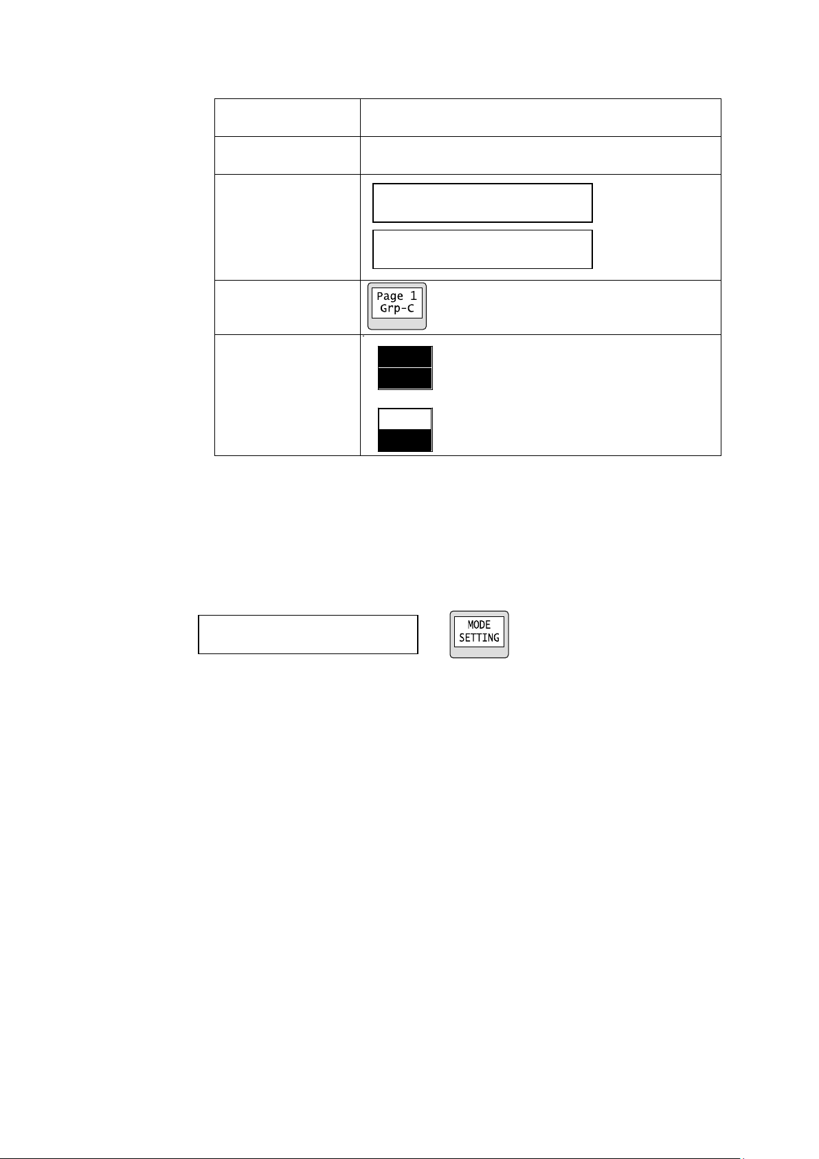
MODE PAGE(PAGE_Grp-A/B/C/D)
PAGE JUMP
Moves the page to the specified number for the specified
group(s).
PAGE UP/DOWN
Moves the page forward or backward by the specified
number for the specified group(s).
MENU display
LCD display
Current PAGE
display
PAGE (UP/DOWN)
Grp-C: 1
PAGE (JUMP)
Grp-C: 1
SETTING>DEF MODE <ENT>
A
B
C
D
PAGE
01
01
01
01
Setting Mode
In MFR-39RU
Displays available menu settings that can be changed using the control knob.
Turn the control knob to select an item, then change the setting.
The items that can be changed are highlighted.
►See section 5-4-3. “Setting Mode Menu (MFR-39RU)”
MENU display Button LCD
77
Page 78
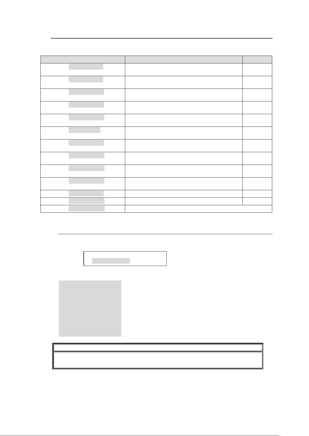
5-4-3. Setting Mode Menu (MFR-39RU)
MENU indication
Description
Reference
SETTING>DEF MODE <ENT>
Allows you to change the remote control panel
start-up default mode.
5-4-3-1
SETTING>DEF DEST <ENT>
Allows you to change the remote control panel
start-up default destination.
5-4-3-2
SETTING>DEF LEVEL <ENT>
Allows you to change the remote control panel
start-up default level.
5-4-3-3
SETTING>PAGE MODE <ENT>
Allows you to select the behavior of the control
knob in Page mode.
5-4-3-4
SETTING>PAGEASSIGN <ENT>
Allows you to select a performance feature for the
PAGE button assignment.
5-4-3-5
SETTING>DSTINHIBIT <ENT>
Allows you to set the inhibit function to a desired
destination.
5-4-3-6
SETTING>SRCINHIBIT <ENT>
Allows you to set the inhibit function to a desired
source.
5-4-3-7
SETTING>NAME TYPE <ENT>
Allows you to select a type for the destination,
source and level name displays.
5-4-3-8
SETTING>TENKEY MOD <ENT>
Allows you to select how to confirm changes in
numeric keypad mode.
5-4-3-9
SETTING>TENKEY NO <ENT>
Allows you to set thresholds of setting ranges in
numeric keypad mode.
5-4-3-10
SETTING>SALVO CLR <ENT>
Allows you to clear the button-assigned Salvo.
5-4-3-11
SETTING>BTN ASSIGN <ENT>
Allows you to assign functions to buttons.
5-4-3-12
SETTING>EXIT <ENT>
Exits the Setting Mode menu.
IMPORTANT
Do not turn off the remote control panel until the BUSY indicator, which lights orange,
goes off when changing modes. Doing so will disable the change.
SETTING>DEF MODE
DESTINATION <ENT>
Setting Mode menu items are as shown below.
Setting Mode menu items
5-4-3-1. DEF MODE
This menu allows you to select a mode to be displayed on the menu display at start-up of
the remote control panel.
Turn the control knob to select a mode, then press the knob to confirm.
DESTINATION : Destination mode
SOURCE : Source mode
LEVEL : Level mode
PAGE_Grp-All : Page mode (all groups)
PAGE_Grp-A : Page mode (Group A)
PAGE_Grp-B : Page mode (Group B)
PAGE_Grp-C : Page mode (Group C)
PAGE_Grp-D : Page mode (Group D)
SETTING : Control knob setting mode
78
Page 79
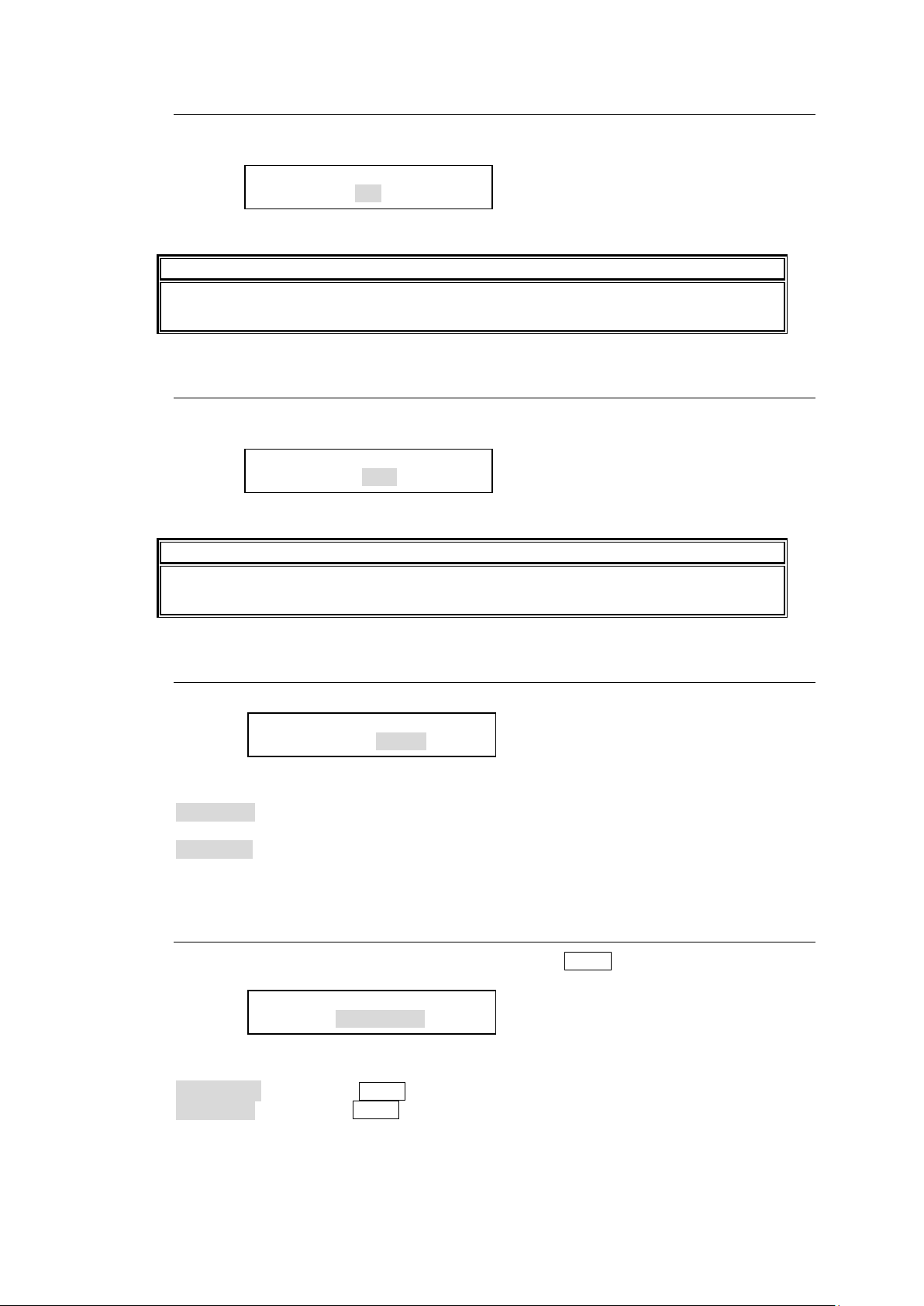
5-4-3-2. DEF DEST
IMPORTANT
Do not turn off the remote control panel until the BUSY indicator, which lights orange,
goes off when changing modes. Doing so will disable the change.
IMPORTANT
Do not turn off the remote control panel until the BUSY indicator, which lights orange,
goes off when changing modes. Doing so will disable the change.
SETTING>DEF DEST
DEF DEST: 1<ENT>
SETTING>PAGE MODE
PAGE MODE :JUMP <ENT>
SETTING>PAGEASSIGN
ASIGN : ONE PAGE <ENT>
SETTING>DEF LEVEL
DEF LEVEL:0001<ENT>
This menu allows you to select a destination to be displayed on the menu display at
start-up of the remote control panel.
Turn the control knob to select a destination, then press the knob to confirm the selection.
5-4-3-3. DEF LEVEL
This menu allows you to select a level to be displayed on the menu display at start-up of
the remote control panel.
Turn the control knob to select a level, then press the knob to confirm the selection.
5-4-3-4. PAGE MODE
This menu allows you to select the behavior for the control knob in Page mode.
Turn the control knob to select a behavior pattern from the below options, then press the
knob to confirm the selection.
UP/DOWN: Every turn of the control knob changes the page one page forward or
backward.
JUMP : Turn the control knob to display the desired page and press the knob to
confirm the display selection.
5-4-3-5. PAGE ASSIGN
This menu allows you to select whether to assign the PAGE button to the selected page
or all pages by a page button assignment procedure.
Turn the control knob to select a performance feature from the below options, then press
the knob to confirm the selection.
ONE PAGE: Assigns the PAGE button to the selected page.
ALL PAGE: Assigns the PAGE button to the button in all pages.
79
Page 80
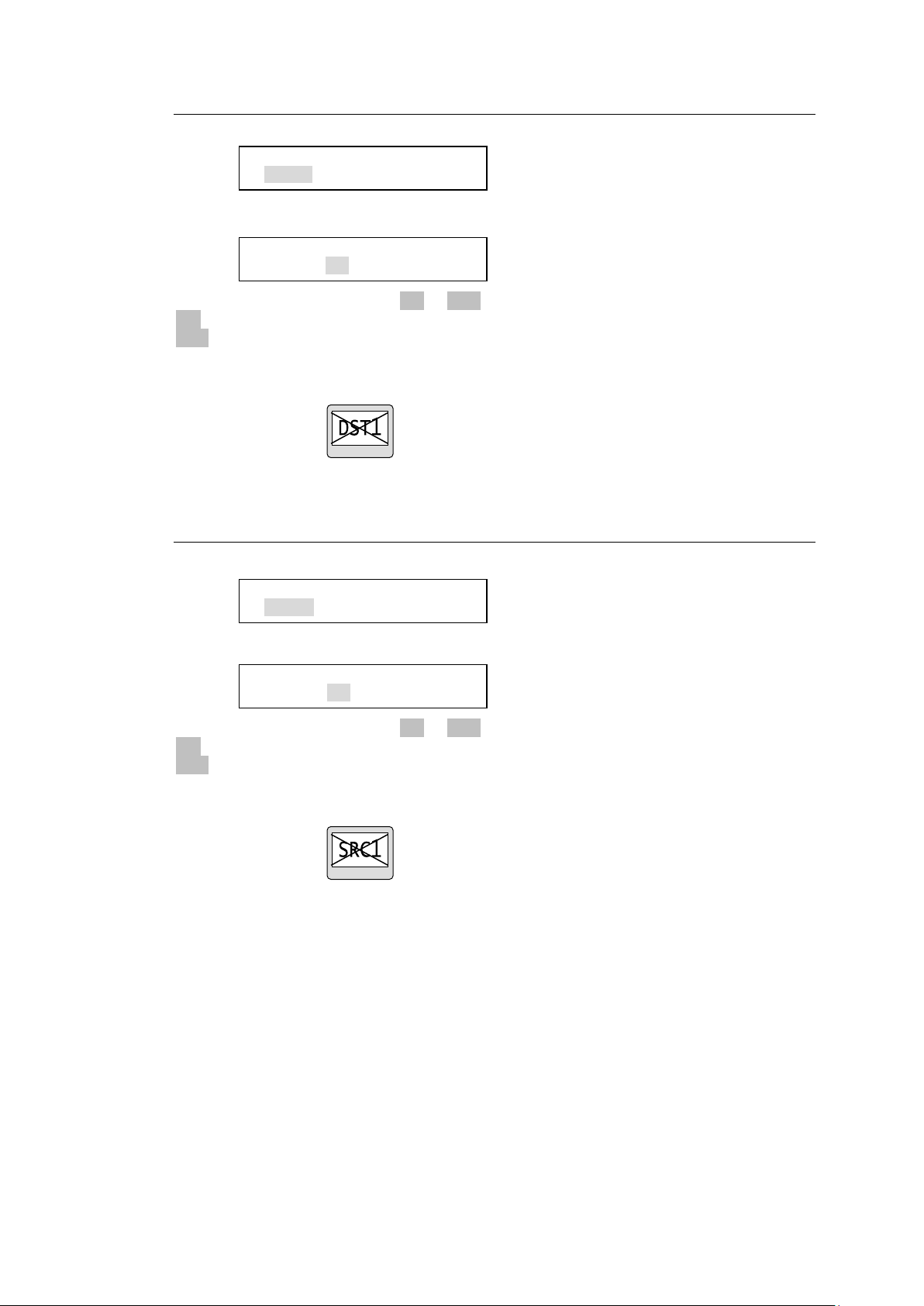
5-4-3-6. DST INHIBIT
SETTING> DSTINHIBIT
DST 1 : ON <ENT>
SETTING>SRCINHIBIT
SRC 1 : OFF <ENT>
SETTING>SRCINHIBIT
SRC 1 : ON <ENT>
SETTING>DSTINHIBIT
DST 1 : OFF <ENT>
Set INHIBIT to enabled or disabled for a destination channel.
Turn the control knob to select a destination channel, then press the knob to confirm the
selection.
Turn the control knob to select ON or OFF, then press the knob to confirm the selection.
ON disables the output selection of the selected destination channel.
OFF cancels the Inhibit setting.
The indication of buttons assigned to the inhibited destination will be crossed.
5-4-3-7. SRCINHIBIT
Set INHIBIT to enabled or disabled for a source channel.
Turn the control knob to select a source channel, then press the knob to confirm the
selection.
Turn the control knob to select ON or OFF, then press the knob to confirm the selection.
ON disables the output selection of the selected source channel.
OFF cancels the Inhibit setting.
The indication of buttons assigned to the inhibited source channel will be crossed.
80
Page 81
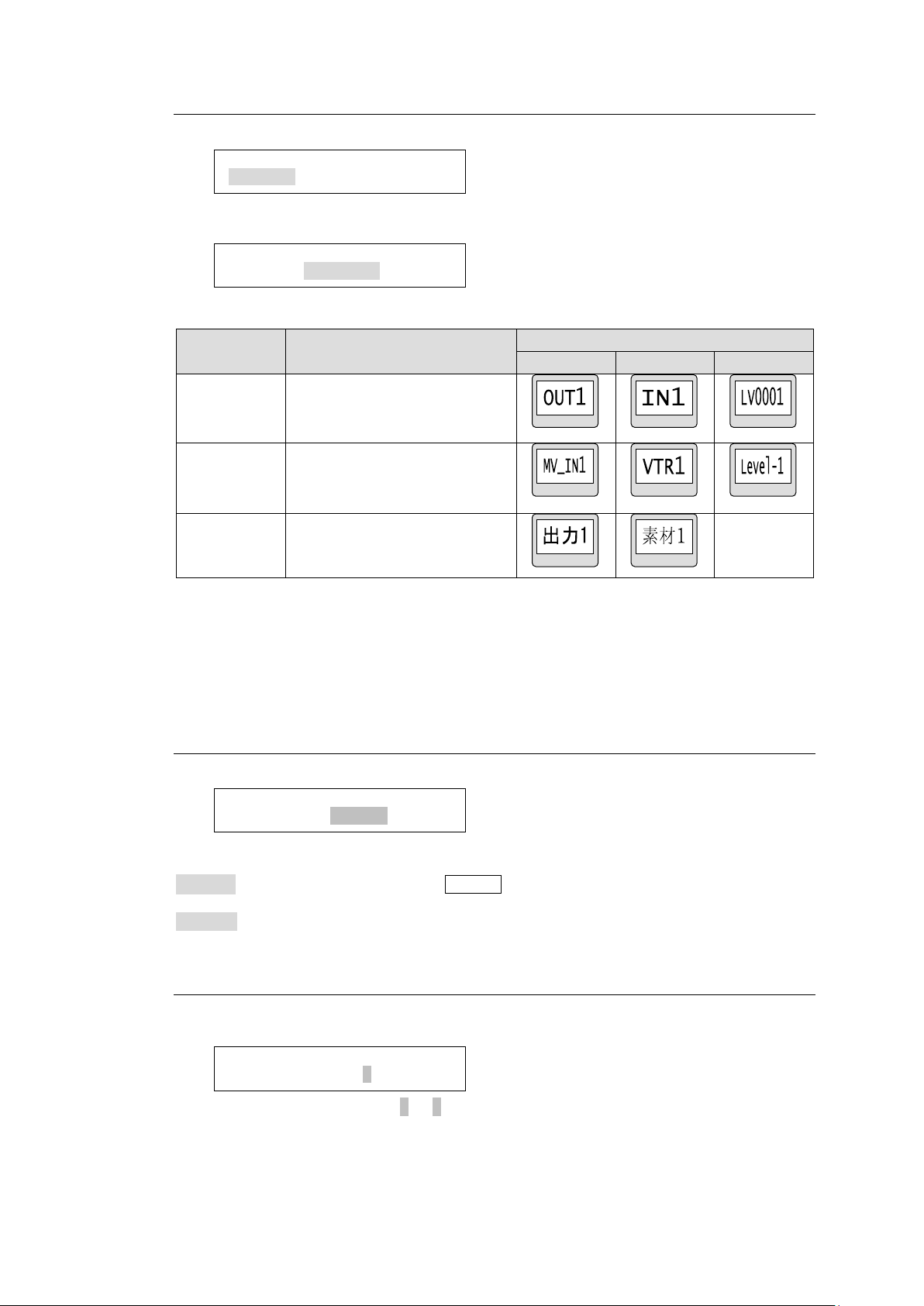
5-4-3-8. NAME TYPE
Display type
Description
Example indication
DST
SRC
LEVEL
PHY NUM
Physical number display
ASCII
Ascii character display
(Alphanumeric characters and
symbols)
KANJI
2-byte character code including
1-byte character code
(Not selectable for LEVEL)
SETTING>TENKEY MOD
INPUT MODE:ENTER <ENT>
SETTING>TENKEY NO
INPUT START NO:0<ENT>
SETTING>NAME TYPE
DST BTN :PHY NUM <ENT>
SETTING>NAME TYPE
DST BTN :PHY NUM <ENT>
This menu allows you to select a name display type for the destination, source and level.
Turn the control knob to select a button group from the destination, source and level
buttons. Press the control knob to confirm the selection.
Turn the control knob to select a display type, then press the knob to confirm the selection.
* When using 2-byte characters:
Up to 8 characters (including one-byte characters) on MFR-39RUA/18RUA/16RUTA
units
Up to 4 characters (including one-byte characters) on MFR-39RU/18RU units.
* Up 14 characters when using only one-byte characters.
5-4-3-9. TENKEY MOD
This menu allows you to change the method to confirm changes in numeric keypad mode.
Turn the control knob to select a method from the below options, then press the knob to
confirm the selection.
ENTER : Enter a value and press the ENTER button on the displayed numeric keypad on
the remote control panel.
DIRECT: Enter a value using the numeric keypad. The value is confirmed.
5-4-3-10. TENKEY NO
This menu allows you to select the start point of each setting between 0 and 1 in numeric
keypad mode.
Turn the control knob to select 0 or 1, then press the knob to confirm the selection.
81
Page 82
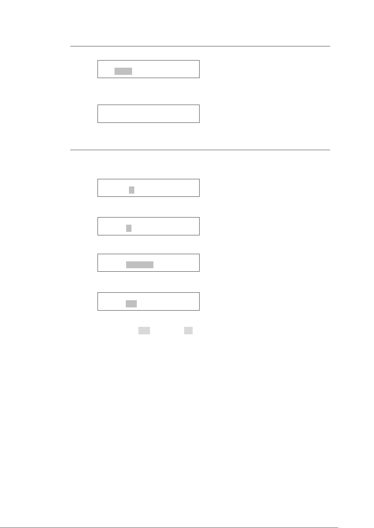
5-4-3-11. SALVO CLR
SETTING>BTN ASSIGN
BTN NO: 1<ENT>
SETTING>BTN ASSIGN
PAGE: 1<ENT>
SETTING>BTN ASSIGN
FUNC:DEST <ENT>
SETTING>BTN ASSIGN
EXEC:NO <ENT>
SALVO DELETE
NO: 1<ENT>
SALVO DELETE
(NO SALVO DATA)
This menu allows you to clear a specific salvo assigned to a button.
Turn the control knob to select a salvo to clear, then press the knob to confirm the
selection.
If any salvo is assigned, the menu display appears as shown below.
5-4-3-12. BTN ASSIGN
This menu allows you to assign button functions.
►See section 5-3 “Function Buttons” for the assignable functions.
Select a button to change the button assignment by turning and pressing the control knob,
or by pressing the desired button.
Select a page to change the button assignment by turning the control knob, then press the
knob to confirm the selection.
Turn the control knob to select a function, then press the knob to confirm the selection. Set
details for the function if necessary.
The menu display asks you to confirm the assignment change as shown above when
necessary settings are complete. To apply the change to the system, turn and press the
control knob to select Yes. Selecting No cancels the change and returns to the menu
display to select buttons.
82
Page 83
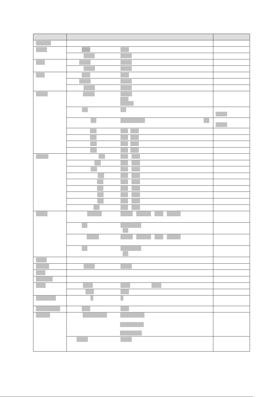
Setting Function Parameters
Function
Parameter
Note
(NONE)
DEST
DEST:XXX
(XXX: Destination channel number)
LEVEL:XXXX
(XXXX: Level)
SRC
SRC:XXXX
(XXXX: Source channel number)
LEVEL:XXXX
(XXXX: Level)
BUS
DEST:XXX
(XXX: Destination channel number)
SRC:XXXX
(XXXX: Source channel number)
LEVEL:XXXX
(XXXX: Level)
PAGE
MODE:JUMP
(JUMP: Jump to a specified page
/UP : Go forward a page
/DOWN: Go back a page)
PAGE:XX
(XX: Page number)
* Effective for
JUMP
RETPAGE:XX
(PREV PAGE: Return to the previous page /XX:
Jump to the next specified page)
* Effective for
JUMP
GROUP-A:ON
(ON / OFF)
GROUP-B:ON
(ON / OFF)
GROUP-C:ON
(ON / OFF)
GROUP-D:ON
(ON / OFF)
MODE
DESTINATION:ON
(ON / OFF)
SOURCE :ON
(ON / OFF)
LEVEL :ON
(ON / OFF)
PAGE_Grp-All:ON
(ON / OFF)
PAGE_Grp-A :ON
(ON / OFF)
PAGE_Grp-B :ON
(ON / OFF)
PAGE_Grp-C :ON
(ON / OFF)
PAGE_Grp-D :ON
(ON / OFF)
SETTING :ON
(ON / OFF)
LOCK
LOCK[S]:OTHER
(NONE / OTHER / ALL / LOCAL)
LOCK function by short press
DEST:XX
(CURRENT: Locks the current destination.
/ XX: Destination Channel number to be locked)
* Effective for
OTHER and ALL
LOCK[L]:NONE
(NONE / OTHER / ALL / LOCAL)
LOCK function by long press
DEST:XX
(CURRENT: Locks the current destination.
/ XX: Destination Channel number to be locked)
* Effective for
OTHER and ALL
TAKE
LEVEL
LEVEL:XXXX
(XXXX: Level)
LINK
TENKEY
SKIP
MODE:FWD
(FWD: Forward / BWD: Backward)
COUNT:XXX
(XXX: number of channels to skip)
MON-OUT
OUT :X
(X:MONITOR OUT)
* MFR-5000/
8000 only
O-PREVIEW
DEST:XXX
(XXX: Destination channel number)
SALVO
MODE:MU RECALL
(MU RECALL: Execute the main unit-assigned
SALVO
/RU RECALL: Execute the button-assigned
SALVO
/RU STORE: Assign a SALVO to a button)
NO:XXXX
(XXXX: Salvo number)
* Effective for
MU RECALL,
and RU RECALL
83
Page 84
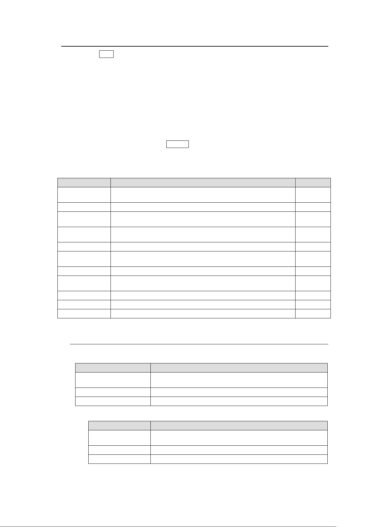
5-4-4. Setting Mode Menu (MFR-39RUA)
MENU indication
Description
Reference
NETWORK
Allows you to change the IP address of the remote control unit
and display the PC-LAN network information.
5-4-4-1
VER/ALARM
Allows you to display the version and alarm information.
5-4-4-2
DEFAULT
Allows you to change the default settings that are loaded when
the remote control unit is powered on.
5-4-4-3
BUTTON
ASSIGN
Allows you to assign functions to user-assignable buttons.
5-4-4-4
INHIBIT
Allows you to enable/disable the INHIBIT function for a channel.
5-4-4-5
NAME TYPE
Allows you to select the display type for Destination, Source and
Level.
5-4-4-6
BRIGHTNESS
Allows you to set the brightness of buttons.
5-4-4-7
RU-RU
CONNECT
Allows you to configure a link system of multiple remote control
units.
5-4-4-8
TENKEY
Allows you to set TENKEY (numeric keypad) operation.
5-4-4-9
PAGE
Allows you to change PAGE settings.
5-4-4-10
SALVO CLEAR
Allows you to clear salvo data stored in buttons.
5-4-4-11
Submenu
Description
RU NETWORK
Allows you to change the IP address of the remote control unit
and display the network information.
PC-LAN NETWORK
Displays the network settings of the PC-LAN port.
PC-LAN REBOOT
Restarts the PC-LAN port.
Menu item
Description
IP
Displays and changes the IP address of the remote control
unit. The lower 8 bits (the fourth byte) represent the Unit ID.
MASK
Displays the subnet mask of the remote control unit.
UNIT NAME
Displays the unit name of the remote control unit.
The current SRC button functions as an EXIT/CANCEL button used for exiting mode or
processes during Setting mode.
Use the following procedures to change settings.
Press a button to turn On/Off.
Use the control knob to change values.
(1) Press to select a desired menu item.
(2) Turn the control knob to change its value.
(3) Press the control knob to confirm the setting.
After menu setting, do not turn off the remote control unit until the BUSY indicator changes
from lit orange to unlit. Otherwise, settings may not be applied.
* To enter Setting mode, press the SETUP button. The BUSY indicator lights orange during
Setting mode. To exit Setting mode, press the EXIT/CANCEL button. Before powering off
the remote control unit, verify that the BUSY indicator is turned off.
Setting Mode menu items are as shown below.
5-4-4-1. NETWORK
The following submenus are available in NETWORK setting mode.
NETWORK > RU NETWORK
84
Page 85
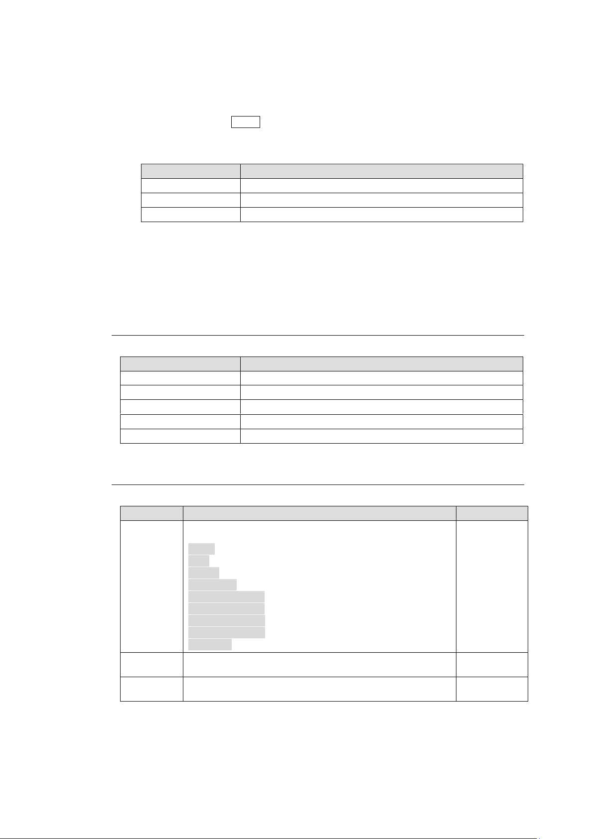
To Change IP Address:
Menu item
Description
IP
Displays the PC-LAN IP address.
MASK
Displays the PC-LAN subnet mask.
GW
Displays the PC-LAN Default Gateway IP address.
Menu item
Description
VERSION
Displays the firmware version.
PS1
Displays the AC adapter 1 status.
PS2
Displays the AC adapter 2 status.
TEMPERATURE
Displays the temperature.
VOLTAGE
Displays the voltage status.
Menu item
Description
Set by
MODE
Allows you to select a mode when the remote control unit is
powered on.
DEST: Destination mode
SRC: Source mode
LEVEL: Level mode
PAGE ALL: Page mode (all groups)
PAGE GROUP A: Page mode (Group A)
PAGE GROUP B: Page mode (Group B)
PAGE GROUP C: Page mode (Group C)
PAGE GROUP D: Page mode (Group D)
SETTING: Setting mode
Pressing a
button
DEST
Allows you to select a destination channel when the remote
control unit is powered on.
CONTROL
LEVEL
Allows you to select a level when the remote control unit is
powered on.
Pressing a
button
(1) Hold down the button where the number to be changed is displayed. The button will
blink.
(2) Turn the control knob to change the number.
(3) Repeat (1) and (2) to change the IP address.
(4) Hold down the current DEST button to confirm the change. The remote control unit will
automatically restart.
NETWORK > PC-LAN NETWORK
NETWORK > PC-LAN REBOOT
To restart the PC-LAN port:
(1) Press REBOOT.
(2) Hold down EXEC HOLD 1s to restart the PC-LAN port while showing "STARTUP" or
"NOW".
5-4-4-2. VER/ALARM
Menu List
5-4-4-3. DEFAULT
Menu List
85
Page 86
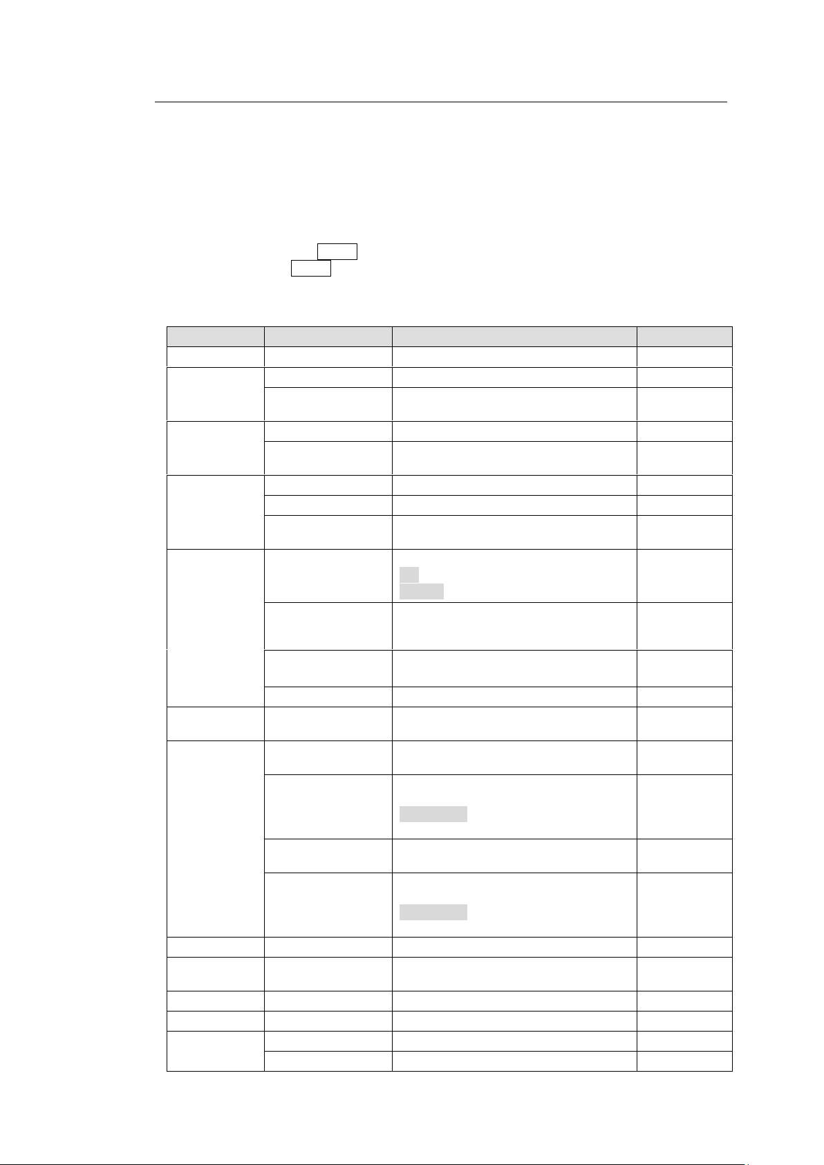
5-4-4-4. BUTTON ASSIGN
FUNC
Parameter
Description
Remarks
NONE
DEST
DESTINATION
Destination channel
LEVEL
Level (Available level number are
displayed.)
SRC
SOURCE
Source channel
LEVEL
Level (Available level number are
displayed.)
BUS
DESTINATION
channel
SOURCE
Source channel
LEVEL
Level (Available level number are
displayed.)
PAGE
TYPE
JUMP: Moves to the set page.
UP: One page forward
DOWN: One page back
FORWARD
Page to jump
When TYPE
is set to
JUMP:
REVERSE
Page to return
HOME: Back to the origin page
GROUP
Page group selection
MODE
TARGET
Mode selection when using the Mode
button
LOCK
TYPE[S]
Lock mode selection for the
short-press of the LOCK button.
DESTINATION[S]
Destination channel setting for the
short-press of destination buttons.
CURRENT: Locks the current
destination
When ALL or
OTHER is
set for
TYPE[S]:
TYPE[L]
Lock mode selection for the
long-press of the LOCK button.
DESTINATION[L]
Destination channel setting for the
long-press of destination buttons.
CURRENT: Locks the current
destination
When ALL or
OTHER is
set for
TYPE[S]:
TAKE
LEVEL
Level (Available level number are
displayed.)
LINK
TENKEY
SKIP
BWD/FWD
Mode selection
COUNT
Number to be skipped
This menu displays the assignment list for PAGE 1.
To Assign Functions to Buttons:
(1) Turn the control knob to select a page.
(2) Press a button for assignment. The button will blink and its information will be
displayed.
(3) Turn the control knob to select a function to the button.
(4) Use the control knob to set the corresponding parameter(s). Once the settings are
complete, the current DEST button blinks and "SAVE" is displayed on the button.
(5) Press the current DEST button to confirm the settings.
To perform another assignment, proceed from Step (1).
FUNC Menu List
86
Page 87
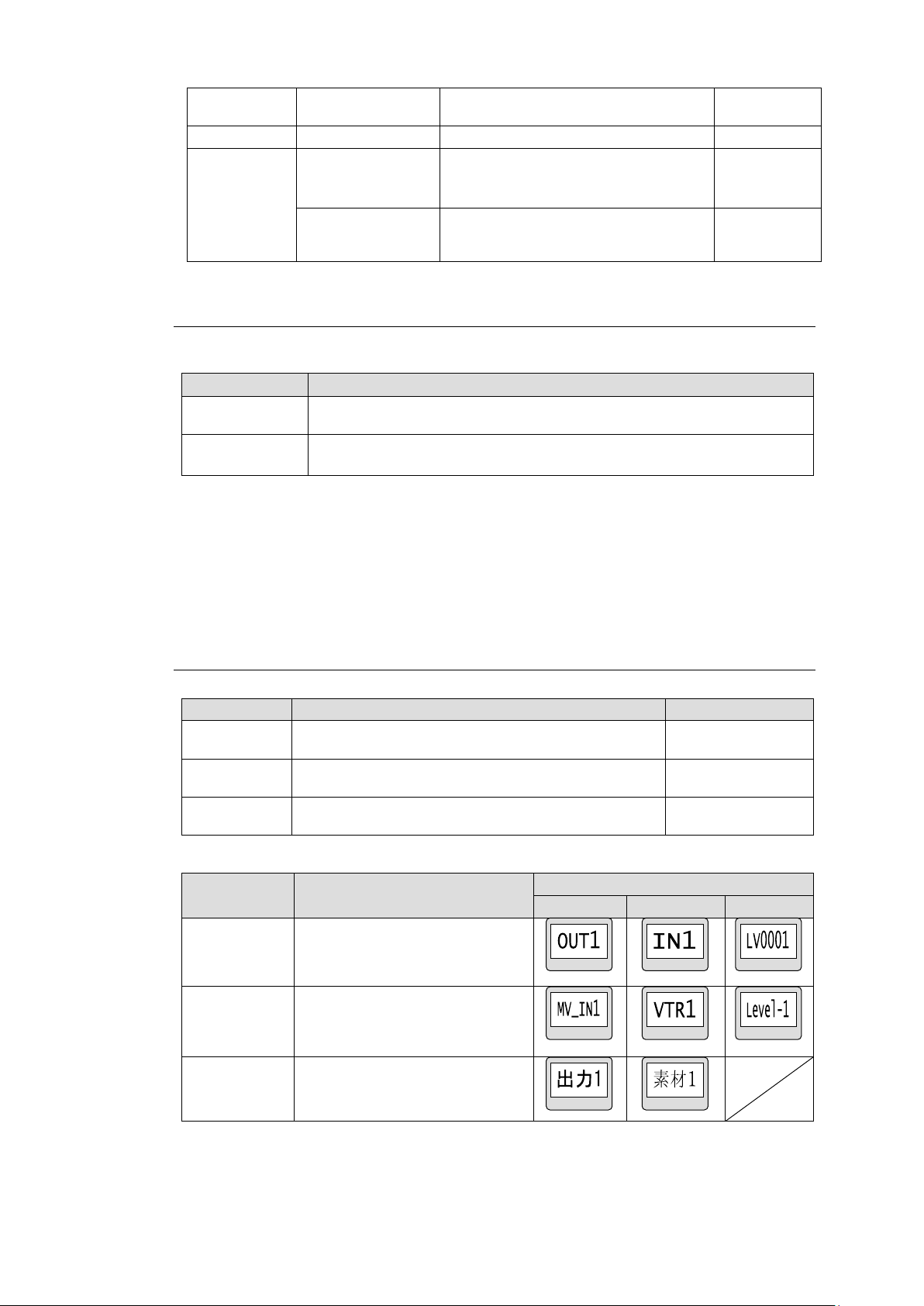
MON-OUT
NO.
Number of monitor output
MFR-5000/8
000 only
O-PREV
DESTINATION
Destination channel
SALVO
TYPE
MU: Execution of an MU salvo.
RU: Execution of an RU button salvo
STORE: Registration of an MU salvo
NO.
Salvo number
When TYPE
is set to MU
or RU:
Submenu
Description
DEST
Allows you to set INHIBIT to enabled / disabled for a destination
channel. Symbol "X" appears on channels when INHIBIT is enabled.
SRC
Allows you to set INHIBIT to enabled / disabled for a source channel.
Symbol "X" appears on channels when INHIBIT is enabled.
Menu Item
Description
Set by
DEST
Allows you to select the display format for a
destination button.
Pressing a button
SRC
Allows you to select a display format for a source
button.
Pressing a button
LEVEL
Allows you to select the display format for a level
button.
Pressing a button
Display
format
Description
Display example
DST
SRC
LEVEL
PHY NUM
Physical number display
ASCII
Ascii character display
(Alphanumeric characters and
symbols)
KANJI
2-byte character code including
1-byte character code
(Not selectable for LEVEL)
5-4-4-5. INHIBIT
The following submenus are available in INHIBIT Setting mode.
INHIBIT > DEST
Displays the destination channel list. Press a channel to enable/disable the INHIBIT
function.
INHIBIT > SRC
Displays the source channel list. Press a channel to enable/disable the INHIBIT function.
5-4-4-6. NAME TYPE
Menu List
Available formats are as shown in the table below.
* When using 2-byte characters:
Up to 8 characters (including one-byte characters) on MFR-39RUA/18RUA/16RUTA
units
Up to 4 characters (including one-byte characters) on MFR-39RU/18RU units
* Up 14 characters when using only one-byte characters
87
Page 88
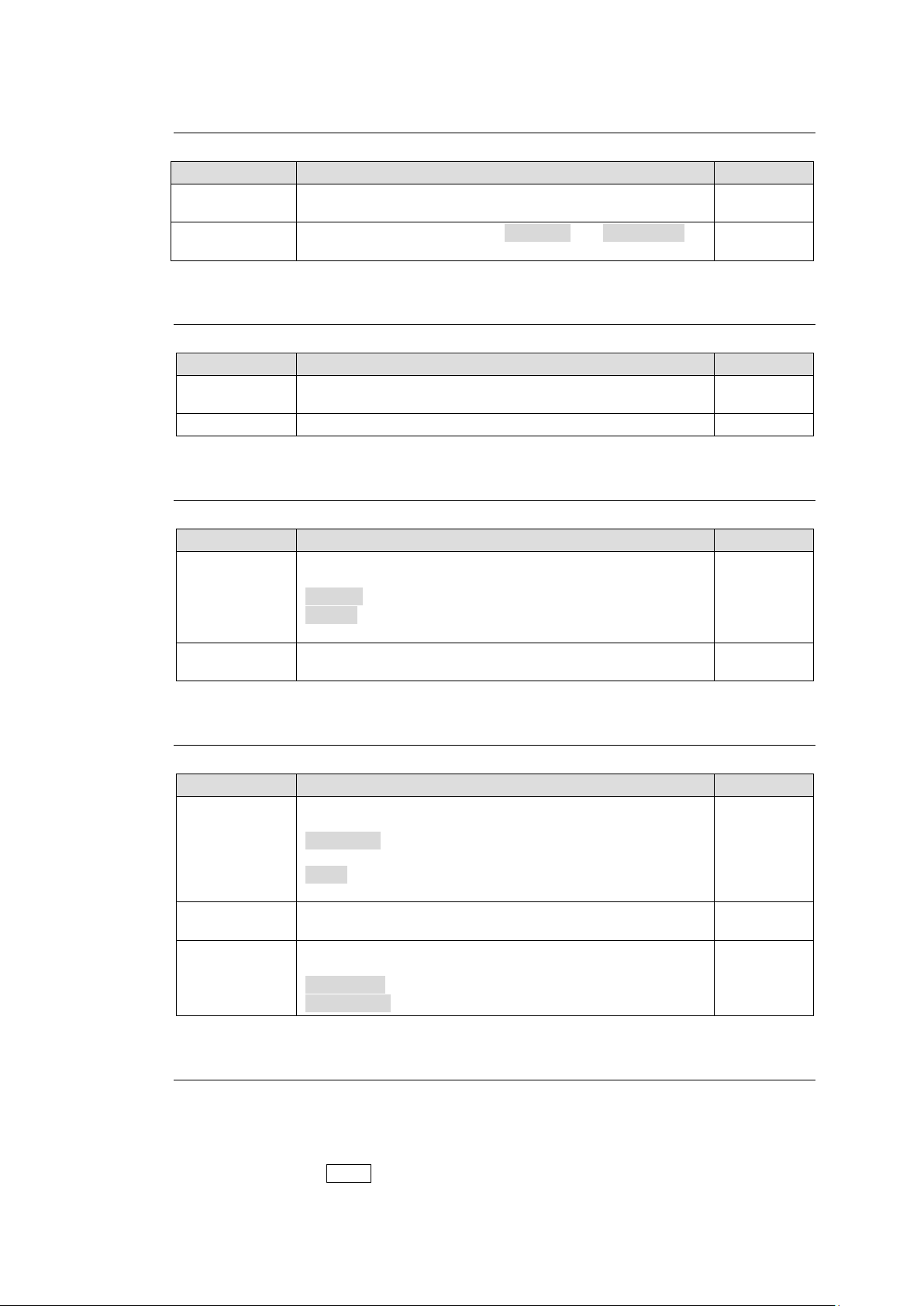
Menu item
Description
Set by
BUTTON
Allows you to select a button.
Pressing a
button
LOW LIGHT
Allows you to select between NORMAL and LOWLIGHT for
dim lighting.
Pressing a
button
Menu item
Description
Set by
CONNECT
Allows you to enable /disable the link of remote control
units.
Pressing a
button
MASTER ID
Allows you to select a link ID.
CONTROL
Menu item
Description
Set by
INPUT MODE
Allows you to select the confirmation method when using
the numeric keypad.
DIRECT: Confirms setting by just pressing a numeric key.
ENTER: Confirms setting by pressing a numeric key then
pressing ENTER.
Pressing a
button
START
This menu allows you to select the start point of each
setting between 0 and 1 in numeric keypad mode.
Pressing a
button
Menu item
Description
Set by
MODE
Allows you to select the control knob behavior in Page
mode.
UP/DOWN: Turns the control knob to move one page
forward/back.
JUMP: Turns the control knob to select a page then
presses the control knob to move to the page.
Pressing a
button
ASSIGN
Allows you to select ONE PAGE or ALL PAGE for PAGE
button assignments.
Pressing a
button
DISPLAY
Allows you to select whether to display unit names for
Current PAGE display (C/D).
PAGE C&D: Current PAGE display for Group C and D.
UNIT NAME: Displays unit names.
Pressing a
button
5-4-4-7. BRIGHTNESS
Menu List
5-4-4-8. RU-RU CONNECT
Menu List
5-4-4-9. TENKEY
Menu List
5-4-4-10. PAGE
Menu List
5-4-4-11. SALVO CLEAR
This menu displays the button-assigned salvo list and allows you to clear salvos.
To Clear a Button-assigned Salvo:
(1) Press a salvo button. The button will blink and "CLEAR" is displayed on the button.
(2) Press the current DEST button.
88
Page 89
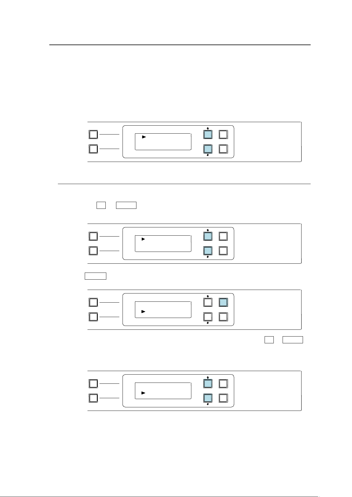
5-5. Operation Using the Menu Display (MFR-16RUD)
D
DST 1
S: SRC 1
PAGE A
(HOLD 3SEC )
PAGE B
LOCK DEST
(HOLD 3SEC )
LOCK PANL
CANCEL
ENTER
MFR-16RUD
REMOTE CONTROL UNIT
D
DST 5
S: SRC 5
PAGE A
(HOLD 3SEC )
PAGE B
LOCK DEST
(HOLD 3SEC )
LOCK PANL
CANCEL
ENTER
MFR-16RUD
REMOTE CONTROL UNIT
D: DST 5
S
SRC 8
PAGE A
(HOLD 3SEC )
PAGE B
LOCK DEST
(HOLD 3SEC )
LOCK PANL
CANCEL
ENTER
MFR-16RUD
REMOTE CONTROL UNIT
D: DST 5
S
SRC 5
PAGE A
(HOLD 3SEC )
PAGE B
LOCK DEST
(HOLD 3SEC )
LOCK PANL
CANCEL
ENTER
MFR-16RUD
REMOTE CONTROL UNIT
The MFR-16RUD, a remote control unit with a display, allows you to select destination channels
and switch crosspoints using the menu display.
Function button assignments are also possible.
Default Display
The name of Current Destination Channel is displayed on the first line.
The name of Source Channel selected for Current Destination is displayed on the second
line.
5-5-1. Crosspoint Switching
To switch crosspoints on the MFR-16RUD, proceed as follows:
(1) Press the UP or DOWN button to change Current Destination to the desired number.
(DST 5 in this example)
(2) Press ENTER.
The cursor automatically moves to the second line (Source side). Press UP or DOWN to
select a source channel.
Note that source names blink during the selection.
89
Page 90
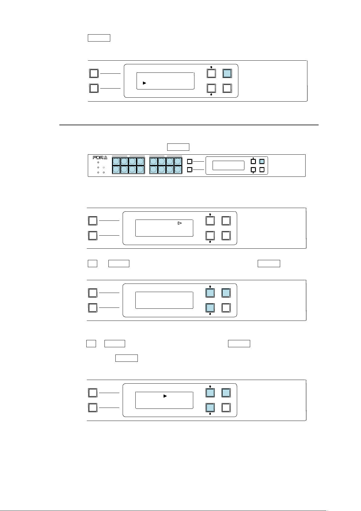
(3) Press ENTER to perform the crosspoint switch. The screen will return to the default
PAGE A
(HOLD 3SEC )
PAGE B
LOCK DEST
(HOLD 3SEC )
LOCK PANL
CANCEL
ENTER
MFR-16RUD
REMOTE CONTROL UNIT
DESTINATION
5
[DST 5 ]
D: DST 5
S
SRC 8
PAGE A
(HOLD 3SEC )
PAGE B
LOCK DEST
(HOLD 3SEC )
LOCK PANL
CANCEL
ENTER
MFR-16RUD
REMOTE CONTROL UNIT
PAGE A
(HOLD 3SEC )
PAGE B
LOCK RESET
POWER
BUSY SETUP
LOCK DEST
(HOLD 3SEC )
LOCK PANL
CANCEL
ENTER
A B
MFR-16RUD
REMOTE CONTROL UNIT
SOURCE
PAGE A
(HOLD 3SEC )
PAGE B
LOCK DEST
(HOLD 3SEC )
LOCK PANL
CANCEL
ENTER
MFR-16RUD
REMOTE CONTROL UNIT
SOURCE
1
[SRC 1 ]
PAGE A
(HOLD 3SEC )
PAGE B
LOCK DEST
(HOLD 3SEC )
LOCK PANL
CANCEL
ENTER
MFR-16RUD
REMOTE CONTROL UNIT
display.
5-5-2. Button Assignment Change
To change button assignments, proceed as follows:
(1) Press a button while holding down ENTER. The button will blink.
The first line will display the function and its parameter currently assigned to the button
and the second line will display its detailed information.
(2) Press UP or DOWN to select a function to be assigned. Press ENTER to apply the
change.
(3) The display changes to the parameter selection according to the selected function.
Press UP or DOWN to select the parameter value. Press ENTER to confirm the selection.
The cursor will move to the next parameter if there are two or more parameters. Set the
value and press ENTER in the same way.
Note that parameters blink during the selection.
When all settings are finished, the screen automatically returns to its default display.
90
Page 91
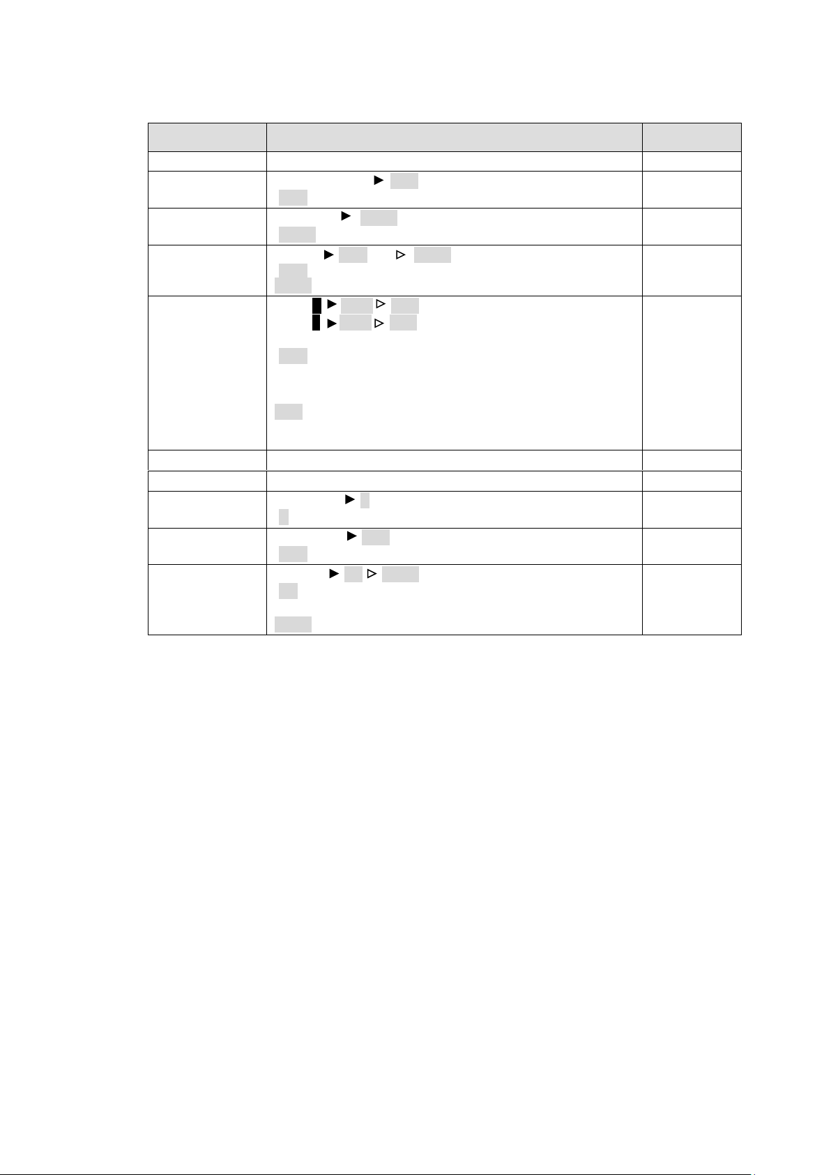
Function
Parameter
Description
(NONE)
None
DESTINATION
DESTINATION XXX
(XXX: Destination Channel number)
SOURCE
SOURCE YYYY
(YYYY: Source Channel number)
BUS
BUS D XXX S YYYY
(XXX: Destination Channel number
YYYY: Source Channel number)
LOCK
LOCKS XXX YYY (Lock function by short press)
LOCKL XXX YYY (Lock function by long press)
(XXX: OTH LOCK OTHER
/ALL LOCK ALL
/LOC LOCK LOCAL
/NON No lock
YYY: CUR Current Destination
/Destination Channel number)
YYY is effective only when XXX is set to OTHER or ALL.
TAKE
None
LINK
None
MON-OUT
MON-OUT X
(X: MONITOR OUT number)
* MFR-5000
only
PREVIEW
PREVIEW XXX
(XXX: Destination Channel number)
SALVO
SALVO XX YYYY
(XX : MU Main Unit Stored Salvo
/RU Remote Control Panel Button Assigned Salvo
YYYY: Salvo number)
Assignable Function/Parameter List
91
Page 92
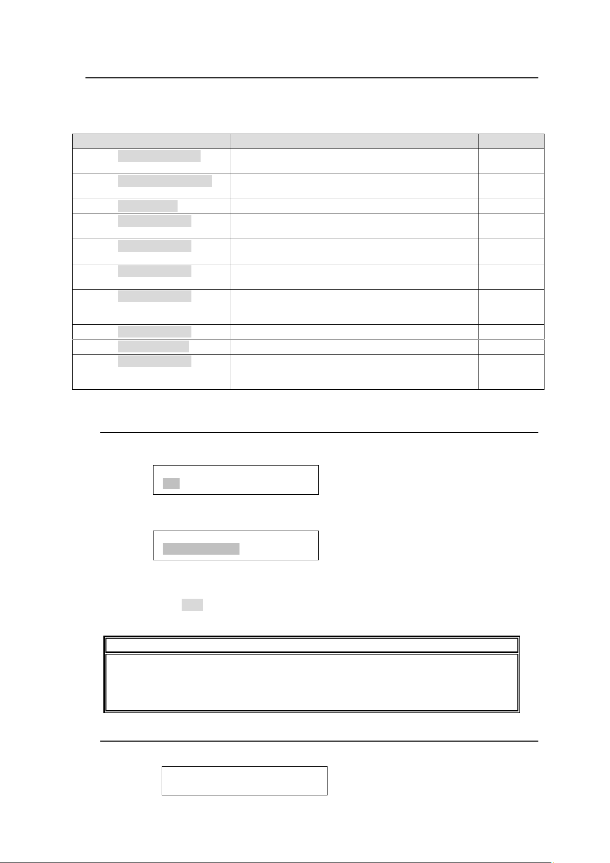
5-6. Setup Menu (MFR-39RU)
Menu display
Description
Reference
SETUP>IP ADDRESS[RU]
<ENT>
Allows you to set the IP address for the remote
control panel. The last 8bits will be the unit ID.
5-6-1
SETUP>SUBNET MASK[RU]
<ENT>
Displays the subnet mask setting in the Remote
Control Unit.
5-6-2
SETUP>PC-LAN[MU]<ENT>
Displays the PC-LAN[MU] menu.
5-6-3
SETUP>RU CONN ID <ENT>
Allows you to set the ID to recognize remote control
panels connected to be used in conjunction.
5-6-4
SETUP>RU CONNECT <ENT>
Allows you to select whether to connect and use
multiple remote control panels.
5-6-5
SETUP>BRIGHTNESS <ENT>
Allows you to set the brightness for buttons and the
menu display.
5-6-6
SETUP>BTN ASSIGN <ENT>
Allows you to assign functions to buttons.
Assignments the same as in the Setting mode menu
can be performed.
5-6-7
SETUP>VER/ALARM <ENT>
Displays version and alarm information.
5-6-8
SETUP>REBOOT <ENT>
Allows you to reboot the unit.
5-6-9
SETUP>EXIT <ENT>
Allows you to exit the Setup menu. The menu returns
to display the menu before entering the SETUP
menu. (The CANCEL button works the same.)
IMPORTANT
The saved IP address is applied when the remote control panel restarts. Selecting NO
will necessitate a manual restart of the remote control panel to apply the new IP
address. The IP address must not be identical to the IP address of the MFR main unit
or other remote control panels.
SETUP>IP ADDRESS[RU]
192.168.001.100<ENT>
SETUP>IP ADDRESS
192.168.001.100<ENT>
SETUP>SUBNET MASK[RU]
255.255.255.000
The SETUP button enables you to use the setup menu. The Setup menu has the following sub
menus. To select a submenu, turn the control knob to select and press to confirm.
Setup Menu Sub-menu List
5-6-1. IP ADDRESS[RU]
This menu allows you to change the IP address of remote control panels. The last 8 bits
(the 4th byte) will be the unit ID.
Turn the control knob to select a byte to be changed. The selected byte will be highlighted.
After changing the value, press the knob. The next byte to be changed will be highlighted.
Pressing the control knob while the 4th byte is highlighted will highlight the whole IP
address, and the changed IP address will be saved. Press the control knob again. The
remote control panel will restart, or a message appears to ask to restart the remote control
panel. Select YES and press the control knob to restart the remote control panel with the
new IP address.
5-6-2. SUBNET MASK[RU]
Displays the subnet mask setting in the Remote Control Unit.
92
Page 93
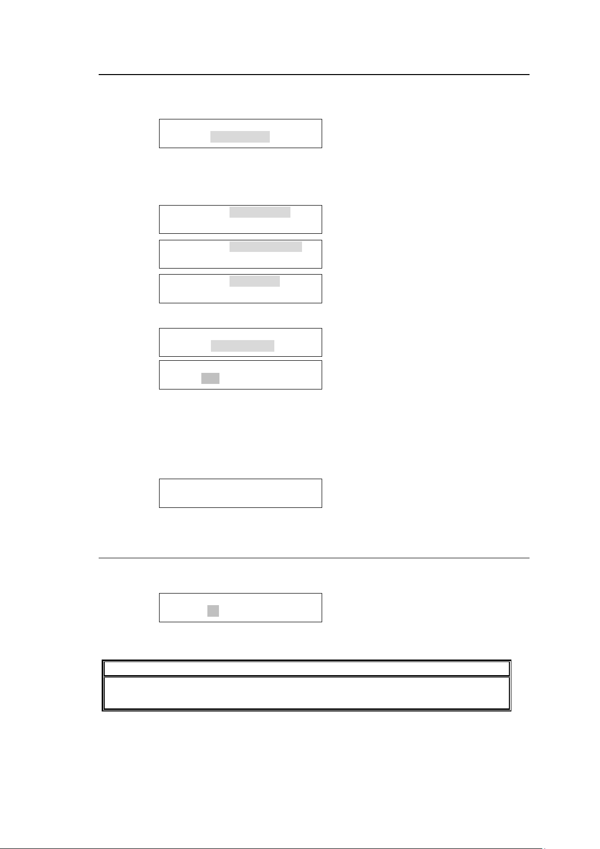
5-6-3. PC-LAN[MU]
IMPORTANT
Do not turn the power of the remote control panel off before the orange BUSY lamp
goes off when changing ID. Doing so will obstruct the settings to be applied.
SETUP>RU CONN ID
UNIT ID: 0<ENT>
SETUP>PC-LAN[MU]>
NET <ENT>
PC-LAN[MU]>IP ADDRESS
192.168.001.012 <ENT>
PC-LAN[MU]>SUBNET MASK
255.255.255.000 <ENT>
PC-LAN[MU]>GATEWAY
000.000.000.000 <ENT>
SETUP>PC-LAN[MU]
GUI REBOOT<ENT>
PC-LAN[MU]>GUI REBOOT
EXEC: NO <ENT>
PC-LAN[MU]>GUI REBOOT
Startup…
The PC-LAN[MU] menu allows you to display the network settings for the PC-LAN port on the
MU and restart the port.
Selecting NET allows you to display the network port settings.
Turning the control knob allows you to scroll through all network settings.
Selecting GUI REBOOT allows you to restart the network port.
To restart the port, turn the control knob to select YES, then press the control knob.
To cancel the process, turn the control knob to select NO. The display will return to the initial
SETUP menu page.
The following message will appear while the port is being restarted.
5-6-4. RU CONN ID
This menu allows you to set the ID for remote control panel IDs to be recognized in the
integrated use of multiple remote control panels.
Turn the control knob to select an ID, then press the knob to confirm the selection. See
section 5-11-2 “Enabling Multi-Panel Operation”
93
Page 94
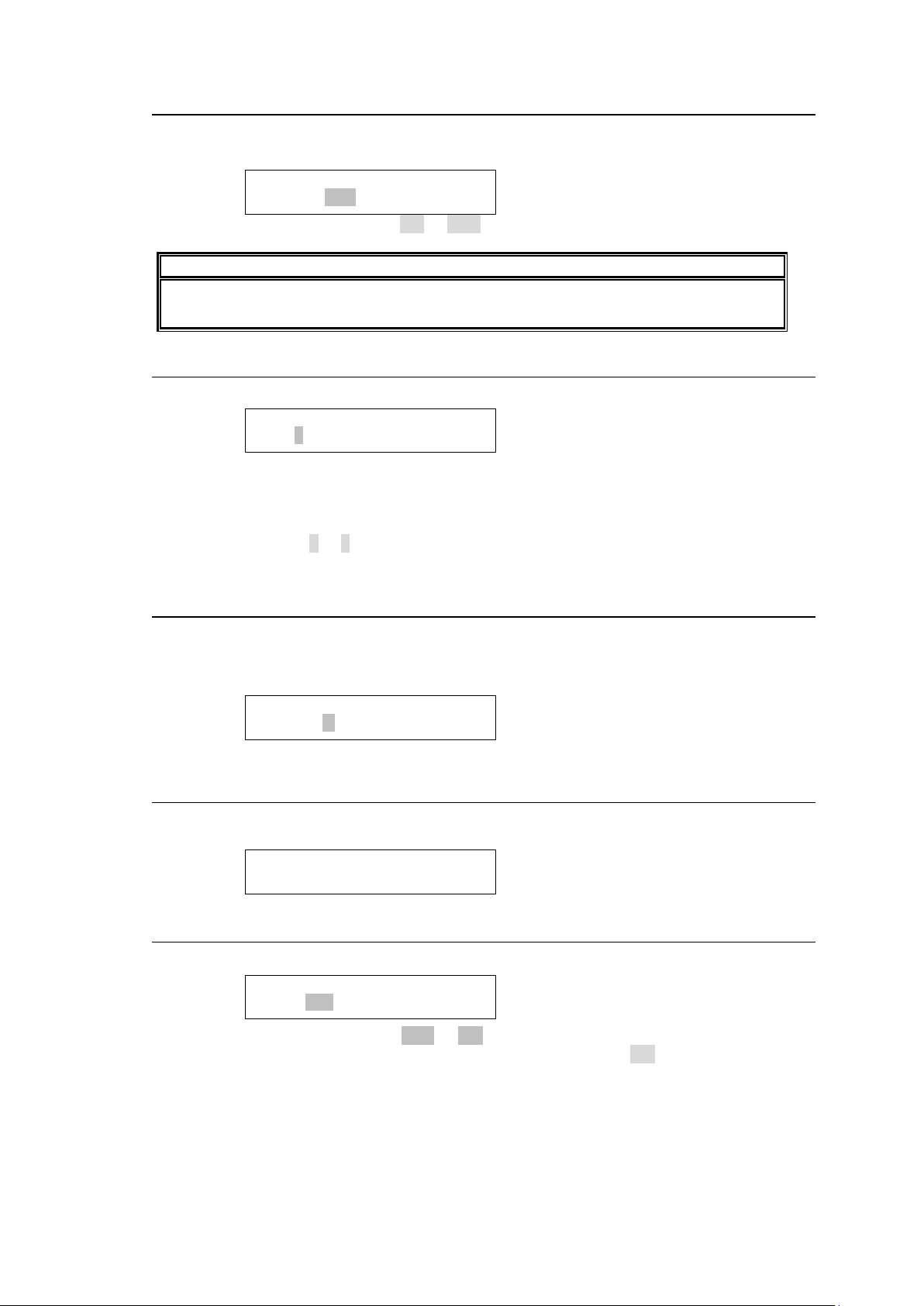
5-6-5. RU CONNECT
IMPORTANT
Do not turn the power of the remote control panel off before the orange BUSY lamp
goes off when changing ID. Doing so will obstruct the settings to be applied.
SETUP>RU CONNECT
ENABLE:OFF<ENT>
SETUP>BRIGHTNESS
BTN:8 MENU:8<ENT>
SETUP>BTN ASSIGN
BTN NO: 1<ENT>
Ver.0.05.1
PS1: Normal
SETUP>REBOOT
EXEC:NO <ENT>
This menu allows you to enable or disable integrated operation of connected multiple
remote control panels.
Turn the control knob to select ON or OFF, then press the knob to confirm the selection.
5-6-6. BRIGHTNESS
This menu allows you to set the brightness for the button LCDs and menu display.
Turn the control knob to select the brightness. Press the control knob to change the BTN
and MENU selection. Pressing the control when MENU is selected confirms the changes.
After settings are complete, press the CANCEL button to exit the menu.
Brightness: (dark) 1 to 8 (bright)
5-6-7. BTN ASSIGN
This menu allows you to assign functions to buttons. The functions that are the same as
those assignable in the Setting mode BTN ASSIGN menu can be assigned.
► See section 5-4-3-12 “BTN ASSIGN” for the setting procedure.
5-6-8. VER/ALARM
This menu displays the version and alarm information. Turn the control knob to scroll the
page.
5-6-9. REBOOT
This menu allows you to execute a restart of the remote control panel.
Turn the control knob to select YES or NO, then press the knob to confirm the selection.
Selecting YES will restart the remote control panel. Pressing NO will return you to the
menu display to select menus.
94
Page 95
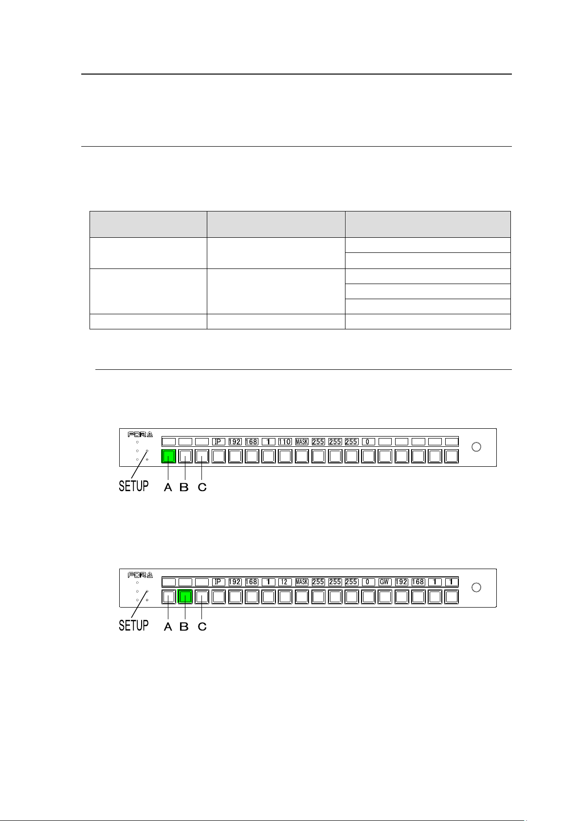
5-7. Setup Menu (MFR-39RUA)
Selection buttons
(See the figures below)
LAN Port
Display / Execution
Button A
Remote Control Unit (RU)
IP address display and change
Subnet mask display
Button B
PC-LAN on Main Unit (MU)
IP address display
Subnet mask display
Default gateway display
Button C
PC-LAN on Main Unit (MU)
Reboot
POWER
BUSY SETUP
LOCK RESET
MFR-18RU
REMOTE CONTROL UNIT
POWER
BUSY SETUP
LOCK RESET
MFR-18RU
REMOTE CONTROL UNIT
The SETUP button allows you to enter Setup Menu mode, in which menu settings can be
performed as shown in Sec 5-4-4. "Setting Mode Menu (MFR-39RUA)."
5-8. Setup Menu (MFR-18RU/18RUA)
The SETUP button allows you to enter Setup Menu mode, in which RU and MU PC-LAN
network settings are displayed, the MU-PC LAN port can be rebooted, and RU network settings
can be changed. The left three buttons are used to select information to be displayed or the
PC-LAN reboot. To exit Setup Menu mode, press the SETUP button again.
5-8-1. Displaying Network Settings
To Display RU IP Address and Subnet Mask
Press SETUP to enter Setup Menu mode. The RU IP address and subnet mask are
displayed as shown below. (If Button A is off (unlit), press Button A.)
To Display IP address, Subnet Mask and Default Gateway of MU PC-LAN
Press Button B in Setup Menu mode. The network settings are displayed as shown below, in
order, as "IP address, Subnet Mask and Default Gateway."
95
Page 96
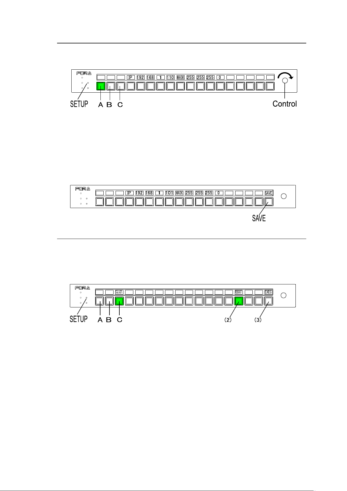
5-8-2. Changing the RU Network Settings
POWER
BUSY SETUP
LOCK RESET
MFR-18RU
REMOTE CONTROL UNIT
POWER
BUSY SETUP
LOCK RESET
MFR-18RU
REMOTE CONTROL UNIT
POWER
BUSY SETUP
LOCK RESET
MFR-18RU
REMOTE CONTROL UNIT
(1) Press SETUP to enter Setup Menu mode. The RU IP address and subnet mask are
displayed as shown below. (If Button A is off (unlit), press Button A.)
(2) Press and hold down a button below the number for change. The number will blink.
(3) Turn the control knob to change the number value. To clear the number setting, press and
hold down the button.
(4) Repeat steps (2) and (3) to change the IP address.
(5) When a number is changed, the SAVE button will blink. Press and hold down SAVE to
confirm the change. The Remote Control Unit will automatically restart.
To cancel the process, display another information without pressing SAVE.
5-8-3. Rebooting MU PC-LAN
(1) Press Button C in Setup Menu mode.
(2) Press and hold down the REBOOT button shown below. The EXEC button will appear.
(3) Press and hold down EXEC. The "PC-LAN Startup" message is displayed during
rebooting. The message will disappear when the reboot is complete.
96
Page 97
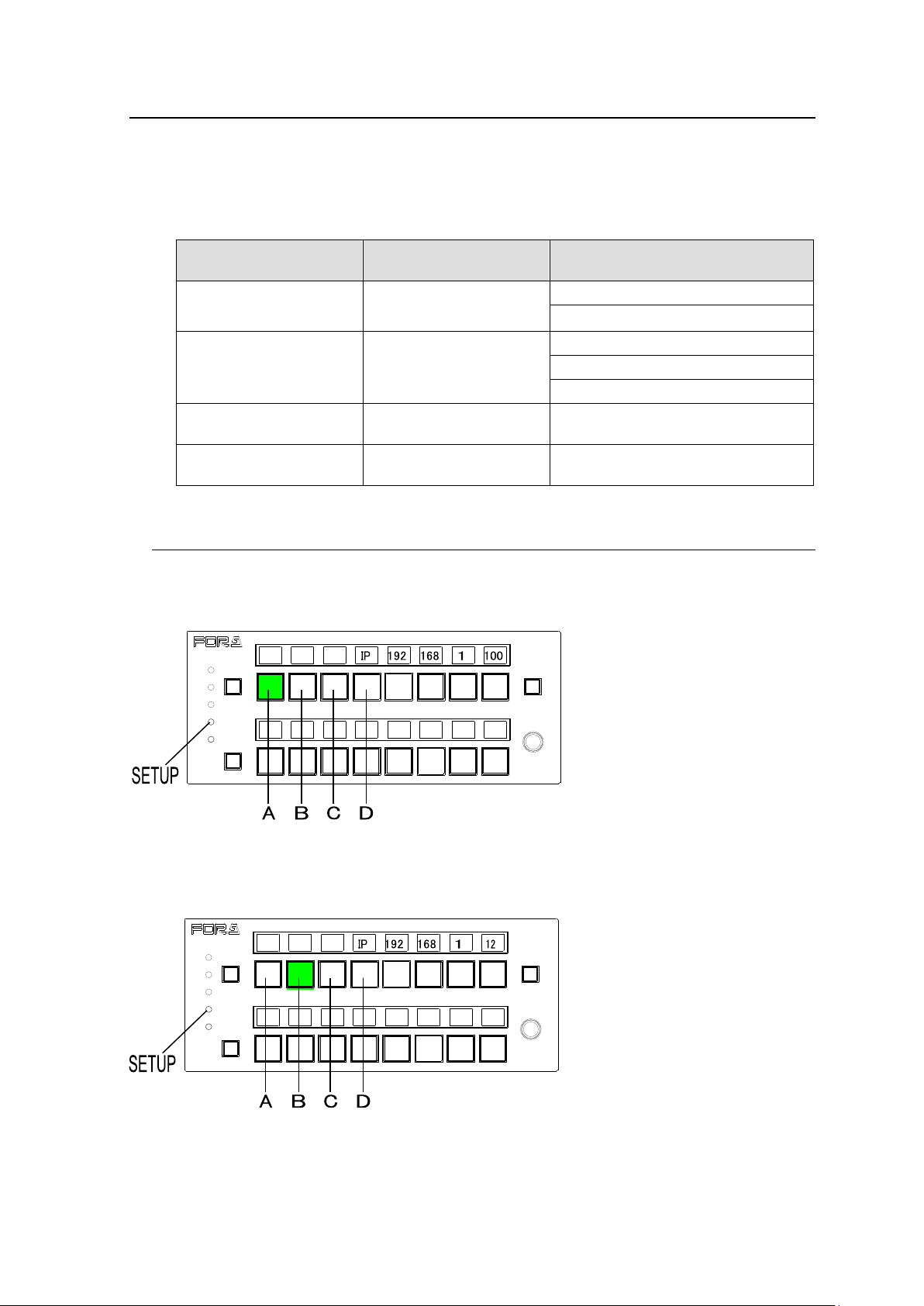
5-9. Setup Menu (MFR-16RUTA)
Selection buttons
(See the figures below)
LAN Port
Display / Execution
Button A
Remote Control Unit
(RU)
IP address display and change
Subnet mask display
Button B
PC-LAN on Main Unit
(MU)
IP address display
Subnet mask display
Default gateway display
Button C
PC-LAN on Main Unit
(MU)
Reboot
Button D
If Button A or B is
selected
Display item change
MFR-16RUTA
REMOTE CONTROL UNIT
LOCK
POWER
BUSY
PAGE A
LOCK
SETUP
RESET
PAGE B
MFR-16RUTA
REMOTE CONTROL UNIT
LOCK
POWER
BUSY
PAGE A
LOCK
SETUP
RESET
PAGE B
The SETUP button allows you to enter Setup Menu mode, in which RU and MU PC-LAN
network settings are displayed, the MU PC-LAN port can be rebooted, and RU network settings
can be changed. The left three buttons are used to select information to be displayed or the
PC-LAN reboot. The fourth button from the left is used to switch network information display. To
exit Setup Menu mode, press the SETUP button again.
5-9-1. Displaying Network Settings
To Display RU IP Address and Subnet Mask
Press SETUP to enter Setup Menu mode. (If Button A is off (unlit), press Button A.)
Pressing Button D displays the RU IP address and repressing it displays the subnet mask.
To Display IP address, Subnet Mask and Default Gateway of MU PC-LAN
Press Button B in Setup Menu mode. The IP address, subnet mask and default gateway are
successively displayed by pressing Button D.
97
Page 98
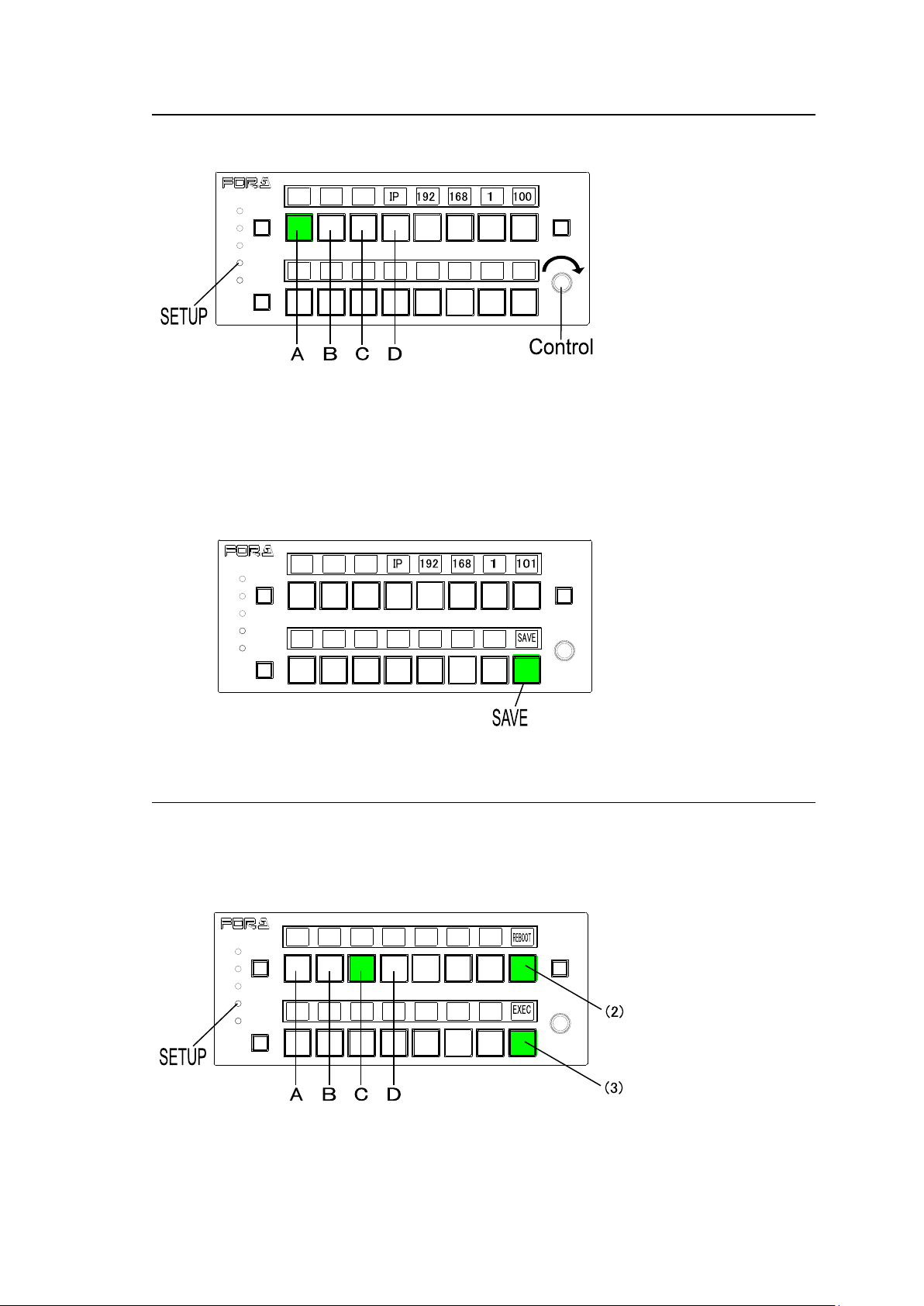
5-9-2. Changing the RU Network Settings
MFR-16RUTA
REMOTE CONTROL UNIT
LOCK
POWER
BUSY
PAGE A
LOCK
SETUP
RESET
PAGE B
MFR-16RUTA
REMOTE CONTROL UNIT
LOCK
POWER
BUSY
PAGE A
LOCK
SETUP
RESET
PAGE B
MFR-16RUTA
REMOTE CONTROL UNIT
LOCK
POWER
BUSY
PAGE A
LOCK
SETUP
RESET
PAGE B
(1) Press SETUP to enter Setup Menu mode. (Press Button A if other information is
displayed.)
(2) Press and hold down a button below the number for change. The number will blink.
(3) Turn the control knob to change the number value. To clear the number setting, press and
hold down the button.
(4) Repeat steps (2) and (3) to change the IP address.
(5) When a number is changed, the SAVE button will blink. Press and hold down SAVE to
confirm the change. The Remote Control Unit will automatically restart.
To cancel the process, display another information without pressing SAVE.
5-9-3. Rebooting MU PC-LAN
(1) Press Button C in Setup Menu mode.
(2) Press and hold down the REBOOT button shown below. The EXEC button will appear.
(3) Press and hold down EXEC. The "PC-LAN Startup" message is displayed during
rebooting. The message will disappear when the reboot is complete.
98
Page 99
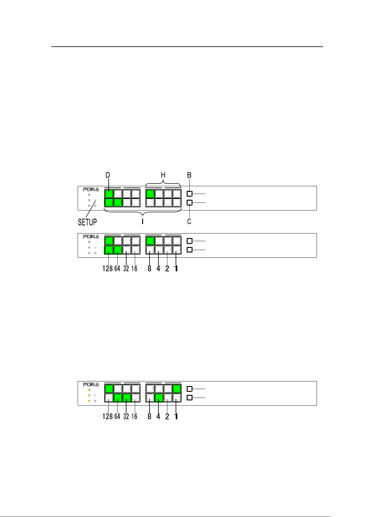
5-10. Setup Menu (Other Remote Control Units)
PAGE A
(HOLD 3SEC)
PAGE B
LOCK RESET
POWER
BUSY SETUP
LOCK DEST
(HOLD 3SEC)
LOCK PANL
A B
REMOTE CONTROL UNIT
MFR-16RU
PAGE A
(HOLD 3SEC)
PAGE B
LOCK RESET
POWER
BUSY SETUP
LOCK DEST
(HOLD 3SEC)
LOCK PANL
A B
REMOTE CONTROL UNIT
MFR-16RU
PAGE A
(HOLD 3SEC)
PAGE B
LOCK RESET
POWER
BUSY SETUP
LOCK DEST
(HOLD 3SEC)
LOCK PANL
A B
REMOTE CONTROL UNIT
MFR-16RU
The SETUP button changes the RU to Setup Menu mode, which allows you to display RU and
MU PC-LAN network settings, reboot the MU PC-LAN port, and change the RU network settings
To exit Setup Menu mode, press the SETUP button again.
IP Address Display
The following procedure shows how to display an IP address in Setup Menu mode using
MFR-16RU as an example.
(1) Press SETUP. All idicators, POWER, BUSY and LOCK, turn on orange to indicate that the
RU enters in Setup Menu mode.
(2) Press Button D. (If Button B or C is lit, press the lit button.)
(3) Press the left-most button (the first octet) of Buttons H.
The first octet number will be displayed on Buttons I. If the MFR-16RU IP address is set to
"192.168.1.100," The eight buttons (8 bits) displays "192" (128+64) by turning the light On or
Off for each bit (On, On, Off, Off, Off, Off, Off, Off).
(4) Press the second button (the second octet) of Buttons H.
The number value will be displayed on Buttons I.
If the MFR-16RU IP assress is set to "192.168.1.100," "168" will be displayed.
(5) Press the third button (the third octet) of Buttons H.
The number value will be displayed on Buttons I.
If the MFR-16RU IP assress is set to "192.168.1.100," "1" will be displayed.
(6) Press the right-most button (the fourth octet) of Buttons H.
The number value will be displayed on Buttons I.
If the MFR-16RU IP address is set to "192.168.1.100," "100" (64+32+4) will be displayed as
shown below (Off, On, On, Off, Off, On, Off, Off).
99
Page 100
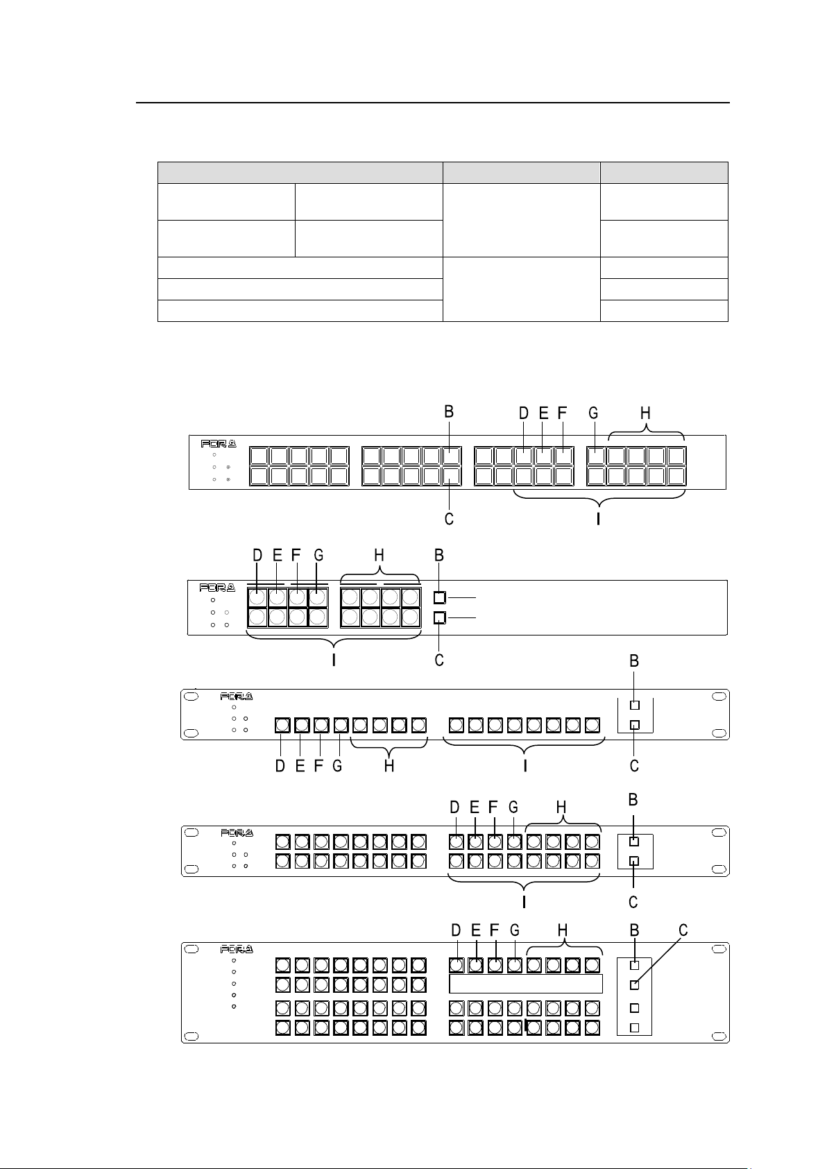
5-10-1. Displaying Network Settings
Button operation
LAN port
Display Info.
Press D.
If B is lit, press B.
If C is lit, press C.
Remote Control Unit
(LAN)
IP address
Press E.
If B is lit, press B.
If C is lit, press C.
Subnet mask
Press B, then D.
PC-LAN on Main Unit
(MU)
IP address
Press B, then E.
Subnet mask
Press B, then F.
Default Gateway
POWER
BUSY SETUP
LOCK RESET
MFR-40RU
REMOTE CONTROL UNIT
POWER
BUSY SETUP
LOCK RESET
FUNCTION
1
2
REMOTE CONTROL UNIT
MFR-32RUW
POWER
BUSY SE TUP
LOCK RES ET
MFR-16RUW
FUNCTION
1
2
REMOTE CONT ROL UNIT
PAGE A
(HOLD 3SEC)
PAGE B
LOCK RESET
POWER
BUSY SETUP
LOCK DEST
(HOLD 3SEC)
LOCK PANL
A B
REMOTE CONTROL UNIT
MFR-16RU
MFR-64RUWREMOTE CONTROL UNIT
1
2
1
2
POWER
BUSY
LOCK
SETUP
RESET
FUNC TION
I
(1) In Setup Menu mode, press a button shown in the table below to display the desired
network setting. Note that button locations vary depending on remote control units.
(2) Press an octet button of Buttons H to select an octet. The right-most button represents the
fourth octet. (See the previous page.)
(3) The octet value will be displayed on Buttons I (eight buttons). (See the previous page.)
MFR-40RU
MFR-16RU (MFR-16RUD)
MFR-16RUW
MFR-32RUW
MFR-64RUW
100
 Loading...