

Page 1

OPERATION
MANUAL
HVS-XT100/100OU
HVS-XT110
Digital Video Switcher
1st Edition
Page 2

Edition Revision History
Edit.
Rev.
Date
Description
Section, Page
1 2013/08/30
1st edition
2
Page 3
Precautions
Operate unit only on the specified supply voltage.
Disconnect power cord by connector only. Do not pull on cable portion.
Do not place or drop heavy or sharp-edged objects on power cord. A damaged cord
can cause fire or electrical shock hazards. Regularly check power cord for
excessive wear or damage to avoid possible fire / electrical hazards.
Ensure unit is properly grounded at all times to prevent electrical shock hazard.
Do not ground the unit to gas lines, units, or fixtures of an explosive or dangerous
nature.
Ensure power cord is firmly plugged into AC outlet.
Do not operate unit in hazardous or potentially explosive atmospheres. Doing so
could result in fire, explosion, or other dangerous results.
Do not allow liquids, metal pieces, or other foreign materials to enter the unit. Doing
so could result in fire, other hazards, or unit malfunction.
If foreign material does enter the unit, turn power off and disconnect power cord
immediately. Remove material and contact authorized service representative if
damage has occurred.
Handle with care to avoid shocks in transit. Shocks may cause malfunction. When
you need to transport the unit, use the original packing materials or alternate
adequate packing.
Stop
Caution
Hazard
MHazard
Caution
Hazard
Caution
Caution
Important Safety Warnings
[Power]
[Grounding]
[Operation]
[Transportation]
3
Page 4
[Circuitry Access]
Do not remove covers, panels, casing, or access circuitry with power applied to the
unit! Turn power off and disconnect power cord prior to removal. Internal servicing /
adjustment of unit should only be performed by qualified personnel.
Do not touch any parts / circuitry with a high heat factor.
Capacitors can retain enough electric charge to cause mild to serious shock, even
after power is disconnected. Capacitors associated with the power supply are
especially hazardous. Avoid contact with any capacitors.
Unit should not be operated or stored with cover, panels, and / or casing removed.
Operating unit with circuitry exposed could result in electric shock / fire hazards or
unit malfunction.
If abnormal smells or noises are noticed coming from the unit, turn power off
immediately and disconnect power cord to avoid potentially hazardous conditions. If
problems similar to above occur, contact authorized service representative before
attempting to again operate unit.
To rack mount or ground the unit, or to install rubber feet, do not use screws or
materials other than those supplied. Otherwise, it may cause damage to the internal
circuits or components of the unit. If you remove the rubber feet attached on the unit,
do not reinsert the screws securing the rubber feet.
The consumables used in unit must be replaced periodically. For further details on
which parts are consumables and when they should be replaced, refer to the
specifications at the end of the Operation Manual. Since the service life of the
consumables varies greatly depending on the environment in which they are used,
they should be replaced at an early date. For details on replacing the consumables,
contact your dealer.
Caution
Hazard
Stop
Caution
Caution
[Potential Hazards]
[Rack Mount Brackets, Ground Terminal, and Rubber Feet]
[Consumables]
4
Page 5
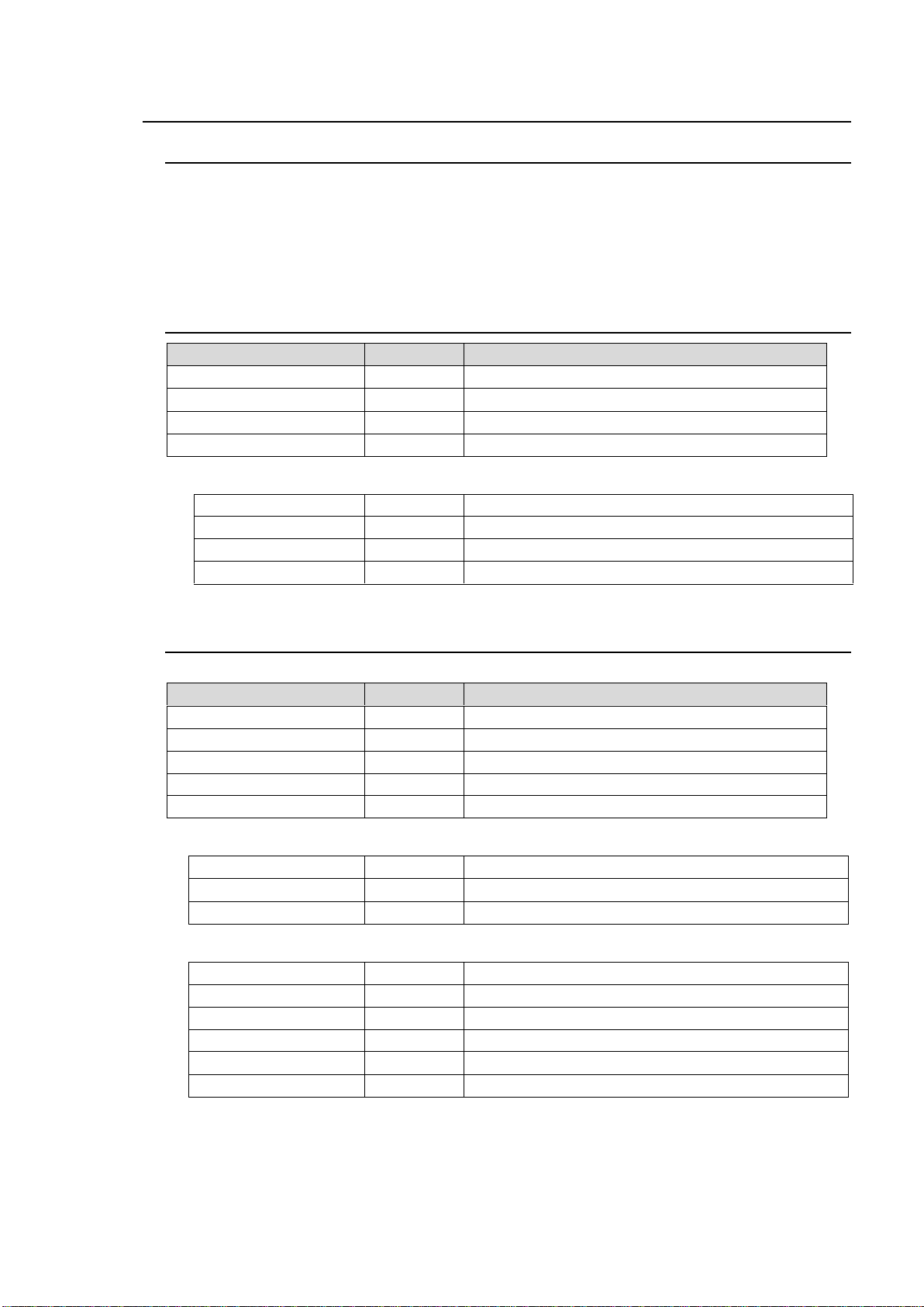
Upon Receipt
ITEM
QTY
REMARKS
HVS-XT110
1
AC Adaptor
1 set
Quick Setup Guide
1
CD-ROM
1
Operation manual (PDF)
HVS-XT100ARC
1
Arcnet I/F Card
HVS-XT100ED
1
Editor Control Software
HVS-XT110PSM
1
Redundant Power Supply Unit
Rack Mount Brackets
1 set
EIA standard type
ITEM
QTY
REMARKS
HVS-XT100
1
Switcher Main Unit (MU)
AC cable
1 set
Retaining clips included
Quick Setup Guide
1
CD-ROM
1
Operation manual (PDF)
Rack Mount Brackets
1 set
EIA standard type
HVS-XT100ARC
1
Arcnet I/F Card
HVS-XT100ED
1
Editor Control Software
HVS-XT100PSM
1
MU Redundant Power Supply Unit
HVS-XT100DI
1
Digital Input Card
HVS-XT100PCI
1-2
VGA/HDMI Input Card
HVS-XT100AI
1-2
Analog Input Card
HVS-XT100DO
1-2
Digital Output Card
HVS-XT100PCO
1-2
VGA/HDMI Output Card
HVS-XT100AO
1-2
Analog Output Card
Unpacking
HANABI Series switchers and their accessories are fully inspected and adjusted prior to
shipment. Operation can be performed immediately upon completing all required connections
and operational settings.
Check your received items against the packing lists below. Check to ensure no damage has
occurred during shipment. If damage has occurred, or items are missing, inform your supplier
immediately.
HVS-XT110 Packing List
Options
HVS-XT100 Packing List
HVS-XT100 (MU) Box
Options
Options (planned for future support)
5
Page 6
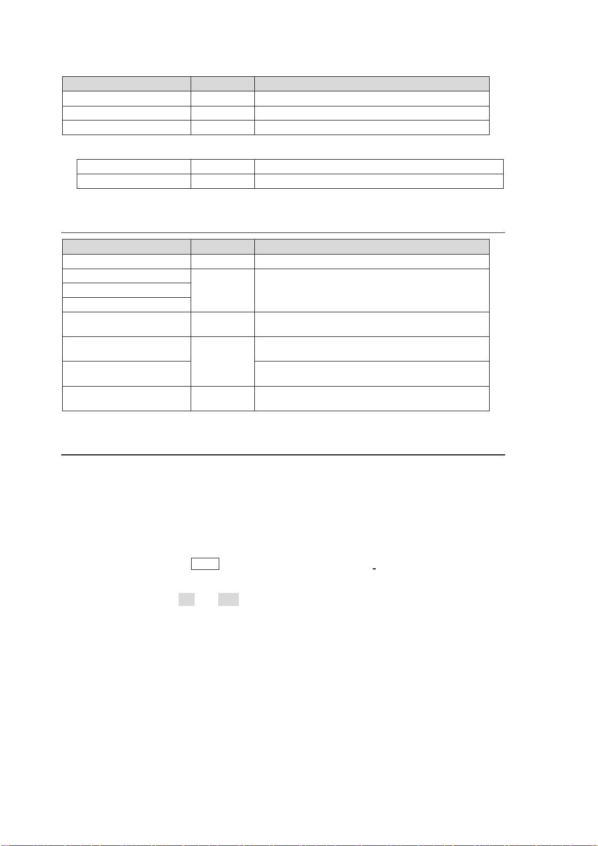
HVS-XT100OU Box
ITEM
QTY
REMARKS
HVS-XT100OU
1
Switcher Control Panel (OU)
LAN cable
1
For HVS-XT100 connection, 10m
AC Adaptor
1 set
AC cable and retaining clip included
HVS-XT100PSO
1 set
OU Redundant Power Supply Unit
Rack Mount Brackets
1 set
EIA standard type
ITEM
QTY
REMARKS
HVS-30RU
1
Remote Control Unit (via RS-422)
HVS-AUX8
Up to 5 total
AUX bus Control Boxes
(HVS-XT100ARC is required)
HVS-AUX16
HVS-AUX32
HVS-AUX8RK or
HVS-AUXRK
---
Remote Kit for Aux bus Control Boxes
HVS-TALR20/32
Up to 3 total
Tally Control Unit
(Relay type) (via RS-422)
HVS-TALOC20/32
Tally Control Unit
(Open Collector type) (via RS-422)
Control Cable
1
BNC cable for ARCNET connection
(10 m) , (BNC 5C2V 75Ω)
Options
HANABI Series Options
About This Manual
This manual is intended to help the user easily operate Hanabi series switchers and make full
use of their functions during operation. Before configuring or operating your system, read this
operation manual thoroughly to ensure you understand the product. Afterwards, it is important to
keep this manual in a safe place and available for future reference.
Font Conventions
The following conventions are used throughout this manual:
Boxed text (for example KEY1) is used to indicate control panel buttons.
Bold text (such as SIGNAL, TYPE and COLOR) is used to indicate setting parameters in
menus and important words.
Shaded text (such as ON and 50.0) is used to indicate menu setting values.
Text enclosed by square brackets (such as [SETUP - SYSTEM]) indicate menu names.
A "double-press" is the act of quickly pressing a control panel button twice in this manual.
6
Page 7

Table of Contents
1. Prior to Starting ......................................................................................................................... 15
1-1. About HVS-XT100 Series Switchers ................................................................................. 15
1-2. Features ............................................................................................................................ 15
2. Panel Descriptions .................................................................................................................... 16
2-1. HVS-XT100OU .................................................................................................................. 16
2-2. HVS-XT100 ....................................................................................................................... 17
2-3. HVS-XT110 ....................................................................................................................... 19
2-4. Interfaces ........................................................................................................................... 21
2-4-1. RS-422 Connector 1-2 ............................................................................................... 21
2-4-2. GPI IN/TALLY OUT Connector .................................................................................. 21
3. Connection ................................................................................................................................ 22
3-1. HVS-XT100 / XT100OU .................................................................................................... 22
3-1-1. Basic Configuration .................................................................................................... 22
3-1-2. Installing the Power Cord Retaining Clamp ............................................................... 23
3-1-3. Optional Configuration ............................................................................................... 24
3-2. HVS-XT110 ....................................................................................................................... 25
3-2-1. Basic Configuration .................................................................................................... 25
3-2-2. Optional Configuration ............................................................................................... 26
3-3. Power ON .......................................................................................................................... 27
3-3-1. HVS-XT100/XT100OU ............................................................................................... 27
3-3-2. HVS-XT110 ................................................................................................................ 27
3-4. System Signal Format Selection at Initial Use .................................................................. 28
3-5. Setting Date, Time and Time Zone at Initial Use .............................................................. 29
4. Menu Operation ........................................................................................................................ 30
4-1. How to Access Menus ....................................................................................................... 30
4-1-1. Menu Access Buttons ................................................................................................ 30
4-1-2. Other Menu Access Buttons ...................................................................................... 31
4-1-3. USER Buttons (Menu Shortcut) ................................................................................. 31
4-2. How to Set Values ............................................................................................................. 32
4-2-1. Displaying Parameters ............................................................................................... 32
4-2-2. Changing Settings or Values Using F1 to F4............................................................. 33
4-2-3. Changing Settings or Values Using the Numeric Keypad ......................................... 34
4-2-4. Changing Settings or Values Using the Joystick ....................................................... 35
4-3. How to Return Settings to Default ..................................................................................... 36
4-3-1. Returning Parameters to Default ............................................................................... 36
4-3-2. Returning Menus to Default ....................................................................................... 36
4-4. How to Back up Settings ................................................................................................... 36
5. Video Sources .......................................................................................................................... 37
5-1. How to Assign User Names to Sources ............................................................................ 37
5-2. How to Assign Sources to Bus Buttons ............................................................................ 38
5-3. Resize Function ................................................................................................................. 39
5-4. INPUT STILL (Freezing Input Video) ................................................................................ 40
5-5. Changing the Side Panel Image ....................................................................................... 41
5-6. XPT DELAY ....................................................................................................................... 41
5-7. Frame Synchronizer .......................................................................................................... 42
7
Page 8

5-8. Adjusting Video Signal Levels............................................................................................ 43
5-8-1. Proc Amp .................................................................................................................... 43
5-8-2. Video Level Clip .......................................................................................................... 43
5-9. Bus Matte ........................................................................................................................... 44
5-9-1. Setting the Matte Color ............................................................................................... 44
5-9-2. Setting the Gradient Matte .......................................................................................... 44
6. Video Outputs ............................................................................................................................ 46
6-1. Aux Outputs ....................................................................................................................... 46
6-1-1. Selecting Video via Bus Buttons ................................................................................. 46
6-1-2. Selecting Video from Menu Selection ......................................................................... 46
6-1-3. AUX Video Switching with Effects .............................................................................. 47
6-2. Preview Set Up .................................................................................................................. 48
6-2-1. Preview Bus Monitoring .............................................................................................. 48
6-2-2. Setting Up Preview Images ........................................................................................ 48
6-3. Clean Set Up ...................................................................................................................... 49
6-4. KEY OUT Set Up ............................................................................................................... 49
6-5. HDMI Output ...................................................................................................................... 50
6-6. Safety Area Markers .......................................................................................................... 51
6-7. Ancillary Data ..................................................................................................................... 52
6-7-1. Passing Incoming Ancillary Data on-through to AUX Outputs ................................... 52
6-7-2. Ancillary Data in PGM and PREV Bus Signals .......................................................... 52
6-8. AUX LINK ........................................................................................................................... 53
6-8-1. Creating AUX Output Link Groups ............................................................................. 53
6-8-2. Creating Signal Link Groups ....................................................................................... 53
6-8-3. Enabling AUX LINK ..................................................................................................... 54
7. Bus Operation ........................................................................................................................... 55
7-1. Selecting Video Sources .................................................................................................... 55
7-1-1. Selecting Video Sources on the PGM/PST ................................................................ 55
7-1-2. Selecting Video Sources for AUX1 to AUX4 .............................................................. 56
7-1-3. Selecting Video Sources for KEY and DSK................................................................ 56
7-2. Button Switching Mode in the M/E Bus .............................................................................. 57
7-3. Setting-up and Using the SHIFT Function ......................................................................... 57
7-3-1. Assigning the SHIFT Function to a Bus Button: ......................................................... 57
7-3-2. Using the SHIFT Function .......................................................................................... 58
8. Transitions ................................................................................................................................. 59
8-1. Transition Block Description .............................................................................................. 60
8-2. Quick Reference for Available Transitions ........................................................................ 60
8-3. Background Transitions ..................................................................................................... 61
8-4. KEY Transitions ................................................................................................................. 63
8-5. DSK Transitions ................................................................................................................. 65
8-5-1. Where DSK Images Appear ...................................................................................... 65
8-6. Simultaneous BKGD and Key Transitions ......................................................................... 66
8-7. Black Transitions ................................................................................................................ 66
8-8. Pattern (WIPE/DVE) Transitions ........................................................................................ 67
8-8-1. Selecting a Pattern ...................................................................................................... 67
8-8-2. Use Limitations for Pattern Transitions ....................................................................... 68
8-8-3. Direct Pattern Function ............................................................................................... 69
8
Page 9

8-8-4. Other Transition Settings ........................................................................................... 71
8-9. Modifying Patterns ............................................................................................................. 72
8-9-1. WIPE Type (No. 0-99) ................................................................................................ 72
8-9-2. DVE Type (No. 100-137)............................................................................................ 74
8-10. KEY/DSK Transitions ...................................................................................................... 76
8-10-1. Setting the KEY/DSK Transition Button Function .................................................... 76
8-10-2. USER Transitions ..................................................................................................... 77
8-11. Transition Settings ........................................................................................................... 78
8-11-1. TRANS Menu ........................................................................................................... 78
8-11-2. Transition Rate ......................................................................................................... 78
8-11-3. Transition Limit ......................................................................................................... 79
8-11-4. Adjusting the Fader Offset ....................................................................................... 79
8-11-5. Endpoint Processing for DVE Transitions ................................................................ 79
9. KEY/DSK .................................................................................................................................. 80
9-1. Luminance Key .................................................................................................................. 81
9-2. Full Key .............................................................................................................................. 82
9-3. Bus Key ............................................................................................................................. 82
9-3-1. Key Link ...................................................................................................................... 83
9-3-2. KEY INSERT MATT ................................................................................................... 83
9-4. Adjusting the Key Signal ................................................................................................... 84
9-5. Changing KEY or DSK Layer Order .................................................................................. 84
9-6. Mask and Invert ................................................................................................................. 85
9-6-1. Inverting Key and Background ................................................................................... 85
9-6-2. Key Masks .................................................................................................................. 85
9-7. Key Edge ........................................................................................................................... 87
9-8. DVE Effects on KEY/DSK ................................................................................................. 88
9-8-1. How to Enable 2D DVEs ............................................................................................ 88
9-8-2. Changing Position and Size ....................................................................................... 89
9-8-3. Changing the Aspect Ratio ........................................................................................ 90
9-8-4. FADE .......................................................................................................................... 90
9-8-5. Rotation ...................................................................................................................... 91
9-8-6. CROP ......................................................................................................................... 93
9-8-7. BORDERS .................................................................................................................. 94
10. Chromakey ............................................................................................................................. 95
10-1. Creating a Chromakey .................................................................................................... 95
10-2. Adjusting Chromakey ...................................................................................................... 97
10-2-1. Adjusting Key Levels ................................................................................................ 97
10-2-2. Adjusting the Foreground Image (Chromakey Color) .............................................. 98
10-2-3. Adjusting Edges ....................................................................................................... 99
10-3. Chromakey Menu .......................................................................................................... 100
10-3-1. [CHR KEY - ADJUST] Menu .................................................................................. 100
10-3-2. [CHR KEY - MATT] Menu ...................................................................................... 101
10-3-3. [CHR KEY - FORGND] Menu ................................................................................ 102
10-3-4. Resetting Chromakey Settings .............................................................................. 102
10-4. Assigning the Chromakey to Another KEY or DSK ...................................................... 103
10-5. Sending Chromakey Signals to Other Devices ............................................................. 103
11. SUB EFFECT Channel ......................................................................................................... 104
9
Page 10

11-1. Selecting a SUB EFFECT Channel and Source Signal ................................................ 104
11-2. MONO COLOR .............................................................................................................. 104
11-3. DEFOCUS ...................................................................................................................... 104
11-4. PAINT COLOR ............................................................................................................... 105
11-5. FREEZE, STROBE, NEGA, MOSAIC ........................................................................... 105
12. Still and Clip Store ................................................................................................................. 106
12-1. Managing Still Images .................................................................................................... 106
12-1-1. Saving Stills............................................................................................................. 106
12-1-2. Displaying Still Images ............................................................................................ 106
12-1-3. Backing-up Stills ..................................................................................................... 107
12-2. Managing Clips .............................................................................................................. 108
12-2-1. Clip Recording ........................................................................................................ 108
12-2-2. Playing Clips ........................................................................................................... 110
12-2-3. Clearing Clip Data ................................................................................................... 111
12-3. Backing-up Still and Clip Data using USB Flash Drive .................................................. 112
12-3-1. Structure for Backing Up Still and Clip Data ........................................................... 112
12-3-2. Setting Automatic Backup to ON ............................................................................ 113
12-3-3. Manually Loading Backup Data .............................................................................. 113
12-3-4. Deleting Backup Data ............................................................................................. 114
12-3-5. Automatic Loading at Startup ................................................................................. 114
12-4. Transferring Image Files ................................................................................................ 115
12-4-1. LAN Connection ...................................................................................................... 115
12-4-2. Image files ............................................................................................................... 116
12-4-3. Sending / Receiving Still Images ............................................................................ 118
12-4-4. Sending Images to Clip Memory ............................................................................ 119
12-5. CG WIPE ........................................................................................................................ 120
12-5-1. CG WIPE Operation Example 1 ............................................................................. 121
12-5-2. Saving CG WIPE Settings ...................................................................................... 122
12-5-3. CG WIPE Menu Quick Reference .......................................................................... 122
13. Multiviewer ............................................................................................................................ 123
13-1. Assigning the Multiviewer to an Output Bus .................................................................. 123
13-2. Selecting the Split-screen Type ..................................................................................... 123
13-3. Video Signal Mapping .................................................................................................... 124
13-4. Setting Up Each Split Area ............................................................................................ 125
13-4-1. Titles ........................................................................................................................ 125
13-4-2. Audio Level Meter ................................................................................................... 126
13-4-3. Safety Area ............................................................................................................. 126
13-4-4. Frame Border .......................................................................................................... 127
13-4-5. On-air Tally.............................................................................................................. 127
13-5. Saving / Loading Screen Layouts .................................................................................. 128
13-5-1. Saving a Screen Layout .......................................................................................... 128
13-5-2. Loading a Screen Layout ........................................................................................ 128
13-5-3. Deleting Screen Layout Data .................................................................................. 128
14. USER Buttons ....................................................................................................................... 129
14-1. USER Button Operation ................................................................................................. 129
14-2. Triggering User Buttons ................................................................................................. 133
15. Event Memory ....................................................................................................................... 135
10
Page 11

15-1. Storing Events ............................................................................................................... 135
15-2. Recalling Events ............................................................................................................ 136
15-3. Protecting / Deleting Event Data ................................................................................... 137
15-4. Event Data ..................................................................................................................... 138
15-4-1. Data Not Saved in Events ...................................................................................... 138
15-4-2. Detailed Data Selection for Saving Events ............................................................ 138
15-4-3. Setting the User Default Menu when Storing an Event ......................................... 139
15-4-4. Detailed Data Selection for Loading Events .......................................................... 139
15-5. Transitions Using Event Recall ..................................................................................... 140
15-6. Loading an Event at Start-up ........................................................................................ 141
16. Macros .................................................................................................................................. 142
16-1. Recording Macros ......................................................................................................... 142
16-2. Executing Macros .......................................................................................................... 143
16-2-1. Operation Example 1 ............................................................................................. 143
16-2-2. Operation Example 2 ............................................................................................. 144
16-2-3. Operation Example 3 (Using KEY/AUX Bus Buttons) ........................................... 144
16-2-4. Operation Example 4 (Using Macro Attach Buttons) ............................................. 144
16-3. Macro Memory Operation ............................................................................................. 145
16-3-1. Overwrite Protection ............................................................................................... 145
16-3-2. Naming Macros ...................................................................................................... 145
16-3-3. Deleting Macros ..................................................................................................... 146
16-4. Macro Execution Buttons .............................................................................................. 147
16-4-1. Changing KEY/AUX Bus Buttons to Macro EXE Buttons ...................................... 147
16-4-2. Macro Attach and Macro Detach ........................................................................... 148
17. File Operation ....................................................................................................................... 149
17-1. USB Flash Drive ............................................................................................................ 149
17-2. Available Files ............................................................................................................... 149
17-3. Saving Data to USB Flash Drives ................................................................................. 150
17-4. Loading Data from USB Flash Drives ........................................................................... 151
17-4-1. Loading Setting Data .............................................................................................. 151
17-4-2. Downloading Image Files ....................................................................................... 151
17-5. Moving between USB Flash Drive Directories .............................................................. 152
17-6. Deleting Files from USB Flash Drives ........................................................................... 153
17-7. Renaming Files in USB Flash Drives ............................................................................ 153
18. System Setup Settings ......................................................................................................... 154
18-1. Selecting System Signal Format ................................................................................... 154
18-2. Crosspoint Switch Timing .............................................................................................. 154
18-3. Selecting a Reference Signal ........................................................................................ 155
18-3-1. To Set Reference Input .......................................................................................... 155
18-3-2. To Set Reference Output ....................................................................................... 155
18-4. Setting Date, Time and Time Zone ............................................................................... 155
18-4-1. Setting Time Using SNTP (Time) Server ............................................................... 156
18-5. Buzzer, Brightness and Screen Saver .......................................................................... 157
18-6. Status Information ......................................................................................................... 158
18-6-1. Checking Alarm Status........................................................................................... 158
18-6-2. Verifying Versions .................................................................................................. 159
18-6-3. Installed Options .................................................................................................... 159
11
Page 12

18-7. Upgrading an Operational Version ................................................................................ 160
18-7-1. Upgrade Procedure................................................................................................. 160
18-7-2. Upgrading the Switcher .......................................................................................... 161
18-7-3. Loading Setting Data .............................................................................................. 161
19. Reboot and Initialize .............................................................................................................. 162
19-1. Rebooting System .......................................................................................................... 162
19-2. System Initialization ....................................................................................................... 162
20. External Device Connection .................................................................................................. 163
20-1. GPI IN/OUT and Tally Outputs ...................................................................................... 163
20-1-1. GPI IN/TALLY OUT Connector ............................................................................... 163
20-1-2. Pin Assignment Examples ...................................................................................... 164
20-1-3. Sending Tally Signals to Tally Units ....................................................................... 167
20-1-4. GPI / Tally Function List .......................................................................................... 168
20-2. VTR / VDCP Control ...................................................................................................... 172
20-2-1. RS-422 Port Settings (VTR/VDCP) ........................................................................ 172
20-2-2. Controlling the VTR ................................................................................................. 173
20-2-3. Playback and Recording ......................................................................................... 174
20-2-4. VDCP Operation ..................................................................................................... 175
20-3. Router Control ................................................................................................................ 180
20-3-1. RS-422 Port Settings .............................................................................................. 180
20-3-2. Setting MFR Link .................................................................................................... 181
20-3-3. Crosspoint Switches Using the Menu ..................................................................... 181
20-3-4. Crosspoint Switches with Control Buttons (Setup) ................................................. 182
20-3-5. Crosspoint Switches with Control Buttons (Execution) .......................................... 183
20-3-6. Displaying Destination / Source Settings................................................................ 183
20-3-7. Saving and Loading Crosspoints ............................................................................ 184
20-3-8. Simultaneous Switching Using Take ...................................................................... 185
20-4. Editor Control (HVS-XT100ED) ..................................................................................... 186
20-4-1. RS-422 Port Settings .............................................................................................. 186
20-4-2. Editor Control Settings ............................................................................................ 186
20-4-3. Editor ON/OFF ........................................................................................................ 187
20-5. AUX Bus Control Box (HVS-AUX8/16/32) ..................................................................... 188
20-5-1. Connecting AUX Boxes .......................................................................................... 188
20-6. Remote Panel (HVS-30RU) ........................................................................................... 189
20-6-1. RS-422 Port Settings (HVS-30RU) ......................................................................... 189
20-6-2. Assigning Sources to PGM/PST Bus Buttons ........................................................ 189
20-6-3. Setting USER Buttons............................................................................................. 190
21. Web-based Control ............................................................................................................... 191
21-1. System Setup ................................................................................................................. 191
21-2. HOME ............................................................................................................................. 192
21-3. TRANS ........................................................................................................................... 193
21-4. BUS TRANS ................................................................................................................... 193
21-5. WIPE PATTERN ............................................................................................................ 194
21-5-1. WIPE PATTERN - WIPE/DVE/Other ...................................................................... 194
21-5-2. WIPE PATTERN - DIRECT .................................................................................... 194
21-6. WIPE MODIFY ............................................................................................................... 195
21-7. KEY and DSK ................................................................................................................. 196
12
Page 13

21-8. COPY SWAP (Web Control Only)................................................................................. 197
21-9. CHROMAKEY ............................................................................................................... 198
21-10. SUB EFF ..................................................................................................................... 199
21-11. STILL ........................................................................................................................... 200
21-11-1. Still Store and Still Capture .................................................................................. 200
21-11-2. Play Clips ............................................................................................................. 201
21-11-3. Backing Up/Loading Stills .................................................................................... 202
21-11-4. Backing-up Still and Clip Data using USB Flash Drive ........................................ 202
21-12. MATTE ........................................................................................................................ 204
21-13. EVENT ......................................................................................................................... 205
21-14. MACRO ....................................................................................................................... 206
21-14-1. To Execute Macros .............................................................................................. 206
21-14-2. To Edit Macros (Web Control Only) ..................................................................... 206
21-15. SETUP ......................................................................................................................... 207
21-15-1. SETUP - SYSTEM ............................................................................................... 207
21-15-2. SETUP - INPUT ................................................................................................... 208
21-15-3. SETUP - OUTPUT ............................................................................................... 209
21-15-4. SETUP - PANEL .................................................................................................. 211
21-15-5. SETUP - GPI/TLY ................................................................................................ 212
21-15-6. SETUP - FUNCTION ........................................................................................... 213
21-16. STATUS ...................................................................................................................... 213
21-17. EXT IF ......................................................................................................................... 214
21-17-1. EXT IF - EDITOR (Option) ................................................................................... 214
21-17-2. EXT IF - TSL TLY ................................................................................................. 214
21-17-3. EXT IF - VTR/VDCP ............................................................................................. 214
21-17-4. EXT I/F - ROUTER ............................................................................................... 218
21-18. Pop-up Menu Operation .............................................................................................. 221
21-18-1. Menu Shortcuts .................................................................................................... 221
21-18-2. Executing User Buttons ....................................................................................... 221
21-18-3. Setting Parameters to Default .............................................................................. 222
21-19. Backing Up Settings .................................................................................................... 222
22. Specifications and Dimensions ............................................................................................ 223
22-1. Specifications ................................................................................................................ 223
22-1-1. HVS-XT100 ............................................................................................................ 223
22-1-2. HVS-XT100OU ....................................................................................................... 224
22-1-3. HVS-XT110 ............................................................................................................ 225
22-2. External Dimensions ..................................................................................................... 227
22-2-1. HVS-XT100 ............................................................................................................ 227
22-2-2. HVS-XT100OU ....................................................................................................... 228
22-2-3. HVS-XT110 ............................................................................................................ 229
Appendix 1. Available Files for Saving and/or Loading ............................................................. 230
Appendix 2. Transition Pattern List ............................................................................................ 231
Index
13
Page 14

Page 15

1. Prior to Starting
1-1. About HVS-XT100 Series Switchers
HVS-XT100 series HANABI switchers are powerful and compact 1M/E video switchers that are
easy to use. They can be used in all types of locations, including at live and sporting events, in
news studios, OB vans, editorial offices and presentation venues, making it the ideal tool for
shaping the imaginative ideas of video creators.
1-2. Features
<HVS-XT100>
Compact HD/SD 1M/E switcher: Main Unit 2U in height
Switcher Processor (Main Unit) and separate Control Panel
HD/SD-SDI 8-input/4-output and single HDMI output
Redundant Power Supply (with HVS-XT100PSM and HVS-XT100PSO options)
<HVS-XT110>
Compact HD/SD 1M/E switcher (3U)
Switcher Processor and integrated Control Panel
HD/SD-SDI 12-input/8-output and single HDMI output
Redundant Power Supply (with HVS-XT110PSM option)
<HVS-XT100/XT110>
Frame synchronizer on IN01 to IN08
Resizing engine on IN05 to IN08
Built-in multiviewer output, supporting various multi-view layouts with title, tally and audio
meter display
2-Key and 2-DSK channels
Chromakey generator
More than 130 of transition patterns including 2D DVE
4-channel DVE for Background, Keys and DSKs
Two upstream effect channels
Transition effects using event-load or AUX-signal switch
Two still stores and two clip stores (approx. 7.5 sec on HD) with backup and data transfer
capabilities
Safety area markers
Internal color-bar generator
Various interfaces
-VTR, Router, Editor and/or Tally Unit connection (RS-422)
-Aux Bus Control Box connection (Arcnet LAN)
-Windows PC, Mac computer, tablet, etc. connection for Web-based control and image data
transfer (Ethernet LAN)
Optional Remote Panel (HVS-30RU)
15
Page 16
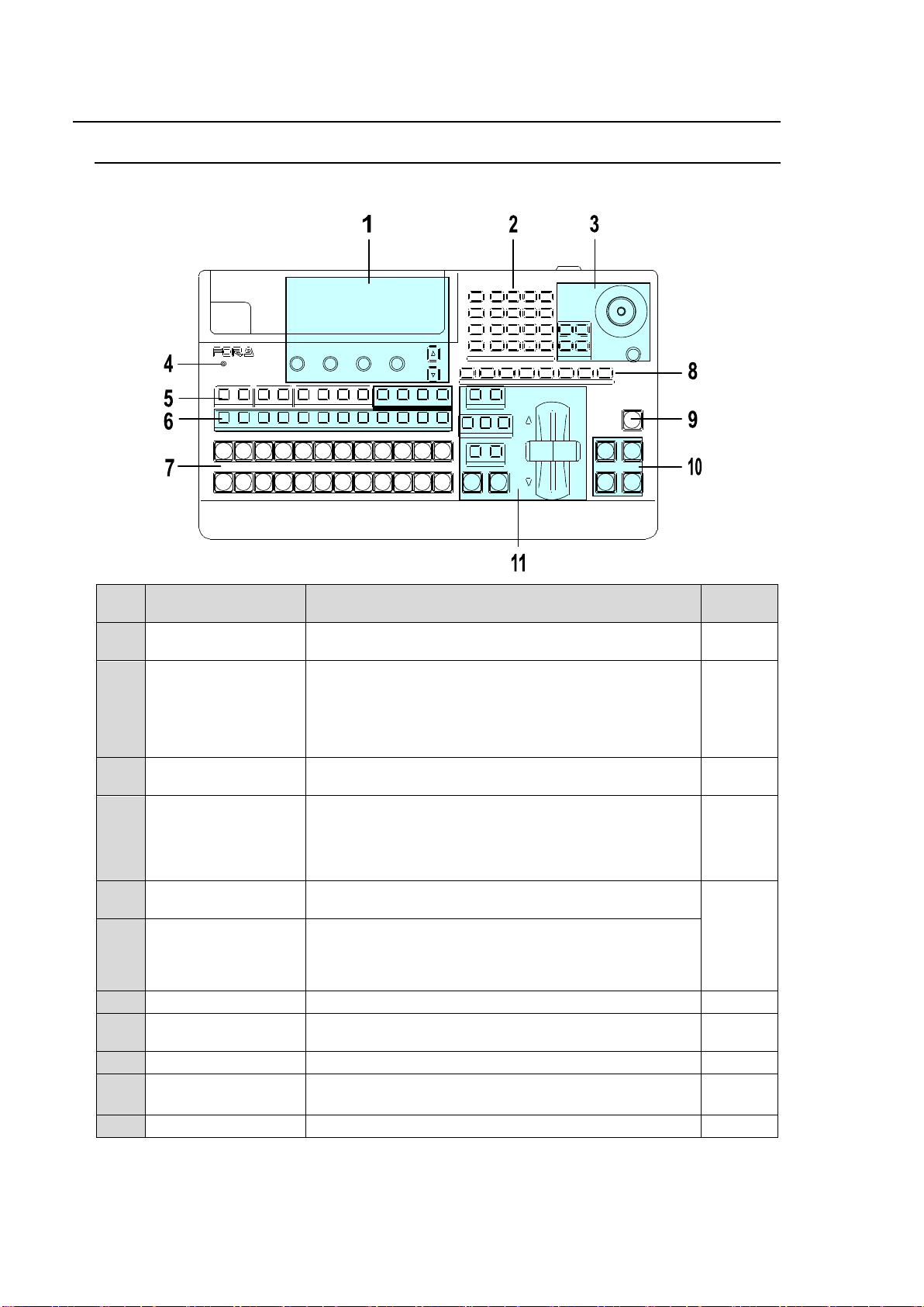
2. Panel Descriptions
No.
Name
Description
Refer to
sec.
1
Menu Control Block
Composed of the menu display, menu control
push-buttons (F1 to F4) and page up/down buttons.
4
2
SELECT/KEYPAD
Block
Multi-function keypad. Four control buttons (MENU,
DIRECT PATT, EVENT, and MACRO) on the left side
change the keypad operation mode, in which 12 buttons
are used for menu display and input, transition pattern
selection, event and macro operations.
4-1-1
4-2-3
8-8-3
15
16
3
JOYSTICK Block
Used to set position, size or color settings in the specific
menu parameters.
4-2-4
4
ALARM indicator
Indicates fan alarm status. Normally unlit, the indicator
blinks red when an alarm occurs. In such case, power
off the system and consult your FOR-A supplier. (It also
blinks red when a power supply does not work in
redundant configuration.)
18-6-1
5
BUS SELECT Block
Used to select a bus, then to select a video in the
KEY/AUX bus (No 7).
6
7
9
13-1
6
KEY/AUX Bus
Used to select video for the bus selected in the BUS
SELECT block (No. 6).
The video can be selected from KEY/AUX bus buttons,
PGM, PREV, CLEAN and MV.
7
PGM/PST (M/E) Bus
Used to select video for the background.
5
8
USER BUTTON
User assignable buttons. Menu shortcuts or functions
can be assigned to these buttons.
14
9
BLACK TRANS
Used to perform black transitions.
8-6
10
KEY/DSK Transition
Block
Used to perform Key/DSK transitions.
8-4
8-5
11
Transition Block
Used to perform background and key transitions.
8
‚o‚n‚r‚h‚s‚h ‚n‚m
DIGITAL VIDEO SWI TCHER HVS-
XT
MENU
7 8 9
4 5 6
DIRECT
PATT
STILL MATT F ILE
KEY2 DSK1 DSK2
0
1 2 3±
EVENT
MACRO CLEAR
RECALL STORE
ENTER
POS ROT
2D DVE
WIPE
POS
MENU
CK EFFECT
TRANS RATE WIPE
SELECT/KEYPA D JOYSTICK
SIZE
(PUSH to DEF)
1 2 3 4 5 6 7 8
USER BUTTON
REV NOR/REV
DIRECTION
BKGD KEY1 KEY2
NEXT TRANSITION
MIX WIPE
TRANSITION TYPE
CUT
KEY1 KEY2
DSK1 D SK2
PGM
PST
1 2 3 4 5 6 7 8 9 10 11 12
1 1 1
1
2 2 2 3 4
2 3 4 5 6 7 8 9 10 11 12
PGM PREV CLEAN MV
KEYER DSK AUX
KEY/AUX
ALARM
F1 F2 F3 F4
PAGE
TRANS
BLACK
AUTO
SETUP
KEY1
ATTACH
DETACH
2-1. HVS-XT100OU
Control Panel
16
Page 17
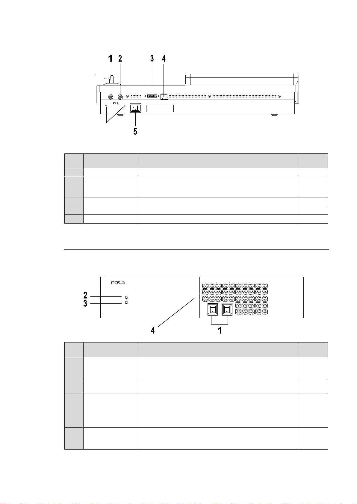
Rear Panel
No.
Name
Description
Refer to
sec.
1
DC IN1
Supply power (12 V DC) using the supplied AC adaptor.
3-1-2
2
DC IN2
Optional power supply (HVS-XT110PSM) for power
redundancy. Supply power (12 V DC) using the supplied
AC adaptor.
3-1-2
3
MODE SW
For maintenance use. Do not change.
4
TO MU
5
Power Switch
Switch used to turn unit power ON / OFF.
No.
Name
Description
Refer to
sec.
1
Power switch1
Power switch2
Switch used to turn unit power ON / OFF.
Set both switches to ON if redundant power supply is
configured.
2
POWER indicator
Power indication is lit green when power switch is set to
ON and power is applied to unit.
3
ALARM indicator
Indicates fan alarm status.
Normally unlit, the indicator blinks red when an alarm
occurs. In such case, power off the system and consult
your FOR-A supplier. (It also blinks red when a power
supply does not work in redundant configuration.)
18-6-1
4
USB MEMORY
Used to connect a USB flash drive for image file import /
export or system setting backup.
(USB1.1, Type-A)
12-3
17
POWE R 2
OFF
ON
DIGITAL VIDEO SWITCH ER
POWER
ALARM
POWE R 1
USB
HVS-XT100
DC12V
1 2
POWER
OFF ON
MODE SW TO MU
Holes for securing
cables with clamps
2-2. HVS-XT100
Front Panel
17
Page 18
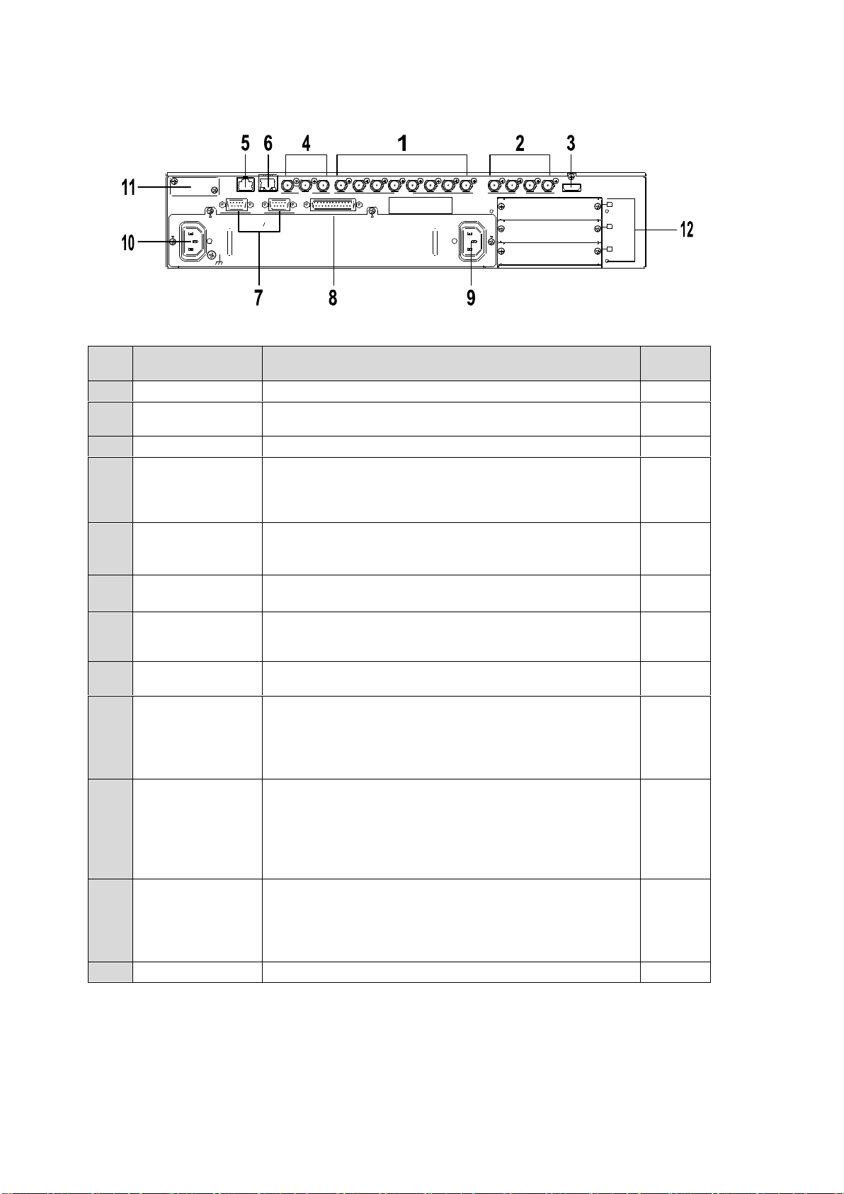
Rear Panel
No.
Name
Description
Refer to
sec.
1
SDI INPUT
Used to input HD/SD SDI video signal. 8 inputs (BNC)
5
2
SDI OUTPUT
Used to output HD/SD SDI video signal. 4 outputs
(AUX1-4) (BNC)
6
3
HDMI
Used to output an HDMI output. (Type A connector)
6-5
4
GENLOCK
(REF IN
REF OUT)
Used to input and output a genlock signal; tri-level sync or
black burst. (BNC)
The center terminal is used for loopthrough connection. It
must be 75-ohm terminated if not looped-through.
18-3
5
TO OU
LAN port , used for HVS-XT100OU connection (RJ-45)
Use the supplied LAN cable with the HVS-XT100OU to
connect the HVS-XT100 and HVS-XT100OU.
6
LAN
Ethernet port used for image transport and web control
100BASE-TX/1000BASE-T (RJ-45)
12-4-1
21
7
RS-422 (1)
RS-422 (2)
Used to connect peripheral devices such as
HVS-30RU,VTR/VDCP devices, Routers.
(9-pin D-sub, female)
2-4-1
8
GPI IN/
TALLY OUT
Used for GPI input/output and Tally output.
(25-pin D-sub, female)
20-1-1
9
AC IN1
Used for connection to AC power source via supplied
accessory cord. (AC 100V-240V 50/60Hz)
Be sure to ground the protective earth terminal before
turning on power to the system to prevent electrical shock.
Use the attached cord clamp to secure the power cord.
10
AC IN2
Optional power supply for power redundancy.
Used for connection to AC power source via supplied
accessory cord. (AC 100V-240V 50/60Hz)
Be sure to ground the protective earth terminal before
turning on power to the system to prevent electrical shock.
Use the attached cord clamp to secure the power cord.
11
ARCNET
Optional Arcnet LAN port (HVS-XT100ARC).
One port is used for HVS-AUX bus Control Box
connection.
The other port is used for loopthrough connection. It must
be 75-ohm terminated if not looped-through.
20-5-1
12
Option card slots
Used for installing input /output expansion cards.
REF OUT 112 3 4 5 6 7 8
2 3 4
A
B
C
REF IN
1 2
2
AC100-240V 50/60Hz INAC100-240V 50/60Hz IN
1
TO OU
LAN GENLOCK SDI INPUT
RS-422 GPI IN/TALLY OUT
HDMI OUTAUX
18
Page 19
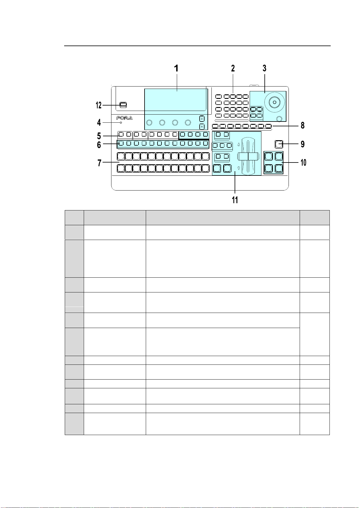
2-3. HVS-XT110
No.
Name
Description
Refer to
sec.
1
Menu Control Block
Composed of the menu display, menu control
push-buttons (F1 to F4) and page up/down buttons.
4
2
SELECT/KEYPAD
Block
Multi-function keypad. Four control buttons (MENU,
DIRECT PATT, EVENT, and MACRO) on the left side
change the keypad operation mode, in which 12 buttons
are used for menu display and input, transition pattern
selection, event and macro operations.
4-1-1
4-2-3
8-8-3
15
16
3
JOYSTICK Block
Used to set position, size or color settings in the specific
menu parameters.
4-2-4
4
ALARM indicator
Indicates fan alarm status. Normally unlit, the indicator
blinks red when an alarm occurs. In such case, power
off the system and consult your FOR-A supplier.
18-6-1
5
BUS SELECT Block
Used to select a bus, then to select a video in the
KEY/AUX bus (No 7).
6
7
9
13-1
6
KEY/AUX Bus
Used to select video for the bus selected in the BUS
SELECT block (No. 6).
The video can be selected from KEY/AUX bus buttons,
PGM, PREV, CLEAN and MV.
7
PGM/PST (M/E) Bus
Used to select video for the background.
5
8
USER BUTTON
User assignable buttons. Menu shortcuts or functions
can be assigned to these buttons.
14
9
BLACK TRANS
Used to perform black transitions.
8-6
10
KEY/DSK Transition
Block
Used to perform Key/DSK transitions.
8-4
8-5
11
Transition Block
Used to perform background and key transitions.
8
12
USB MEMORY
Used to connect a USB flash drive for image file import /
export or system setting backup.
(USB1.1, Type-A)
12-3
17
USB MEMORY
DIGITAL VIDEO SWITCHER HVS-
XT
SIZE
(PUSH to DEF)
1 2 3 4 5 6 7 8
USER BUTTON
REV NOR/REV
DIRECTION
BLACK
TRANS
BKGD KEY1 KEY2
NEXT TRANSITION
MIX WIPE
KEY1 KEY2
TRANSITION T YPE
AUTO CUT DSK1 DSK2
ALARM
F1 F2 F3 F4
PAGE
1 1 1
1
2 2 2 3 4
2 3 4 5 6 7 8 9 10 11 12
KEYER DSK AUX
KEY/AUX
PGM PREV CLEAN MV
PGM
PST
1 2 3 4 5 6 7 8 9 10 11 12
MENU ATTACH
DIRECT
PATT
DETACH
SETUP
KEY1
POSITION
POS ROT
2D DVE
WIPE
POS
MENU
JOYSTICK
8 9
4 5 6
STILL M ATT FILE
KEY2 DSK1 DSK2
EVENT
MACRO
1 2 3
0
CLEAR
RECALL STORE
ENTER
CK EFFECT
TRANS RATE WIPE
SELECT/KEYPAD
±
7
Control Panel
19
Page 20
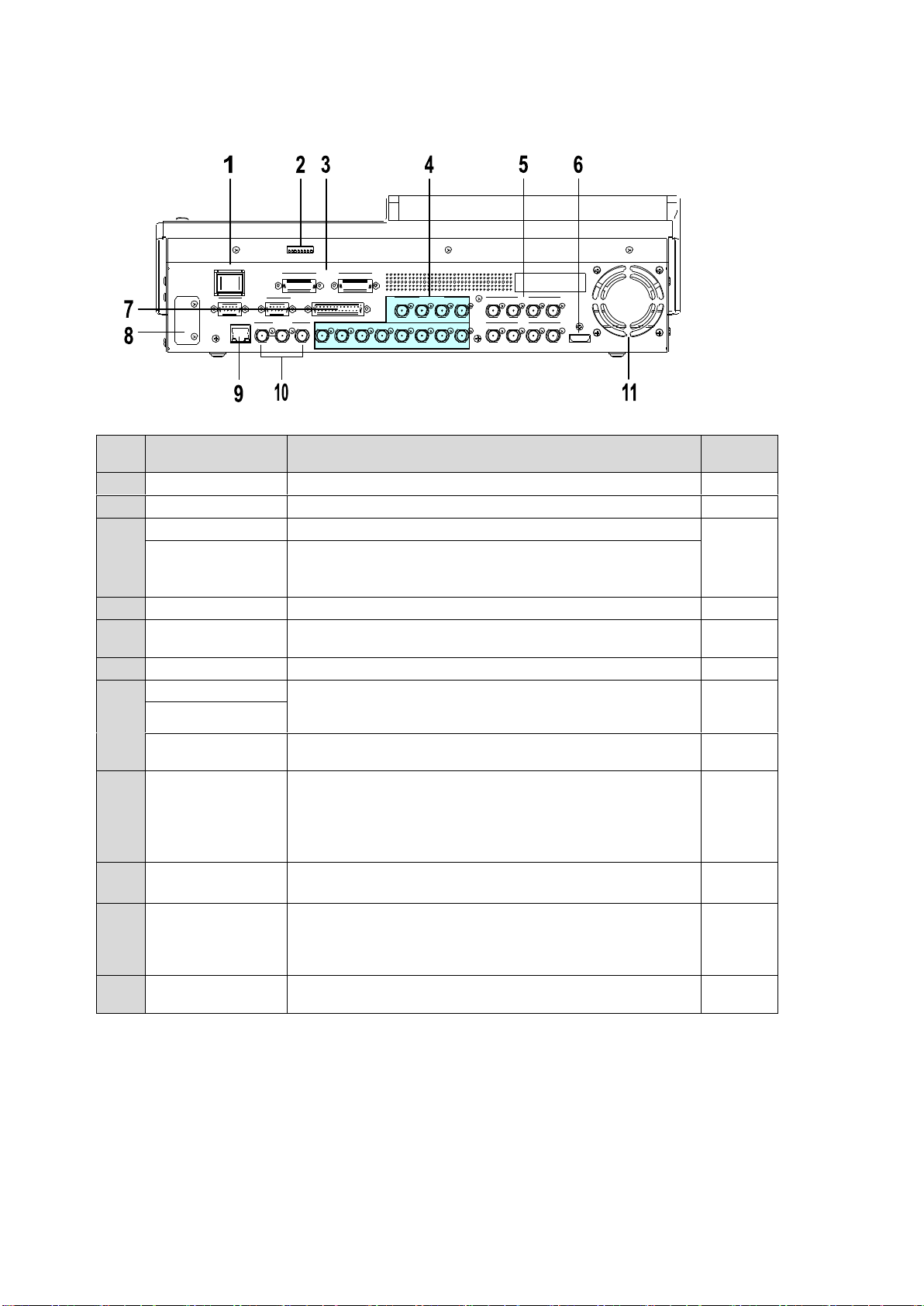
Rear Panel
No.
Name
Description
Refer to
sec.
1
Power Switch
Switch used to turn unit power ON / OFF.
2 MODE SW
For maintenance use. Do not change.
3 DC IN1
Supply power (12 V DC) using the supplied AC adaptor.
3-3
DC IN2
Optional power supply (HVS-XT110PSM) for power
redundancy.
Supply power (12 V DC) using the supplied AC adaptor.
4
SDI INPUT
Used to input HD/SD SDI video signal. 12 inputs (BNC)
5
5
SDI OUTPUT
Used to output HD/SD SDI video signal. 8 outputs
(AUX1-8) (BNC)
6
6
HDMI
Used to output an HDMI output. (Type A connector)
6-5
7
RS-422 (1)
Used to connect peripheral devices such as
HVS-30RU,VTR/VDCP devices, Routers.
(9-pin D-sub, female)
2-4-1
RS-422 (2)
GPI IN/
TALLY OUT
Used for GPI input/output and Tally output.
(25-pin D-sub, female)
20-1-1
8
ARCNET
Optional Arcnet LAN port (HVS-XT100ARC).
One port is used for HVS-AUX bus Control Box
connection.
The other port is used for loopthrough connection. It must
be 75-ohm terminated if not looped-through.
20-5-1
9
LAN
Ethernet port used for image transport and web control
100BASE-TX/1000BASE-T (RJ-45)
12-4-1
21
10
GENLOCK
(REF IN
REF OUT)
Used to input and output a genlock signal; tri-level sync or
black burst. (BNC)
The center terminal is used for loopthrough connection. It
must be 75-ohm terminated if not looped-through.
18-3
11
Cooling Fan
Used to air cool the unit to prevent overheating. Do not
block the ventilation openings.
18-6-1
REF OUT 1 12 3 4 5 6 7 8 2 3 4REF IN
HDMI OUT
AUX
5 6 7 8
AUX
LAN
SDI INPUT
9 10 11 12
SDI INPUT
GPI IN/TA LLY OUT
DC12V IN
1 2
MODE SW
POWER
OFF ON
GENLOCK
RS-422
1 2
20
Page 21
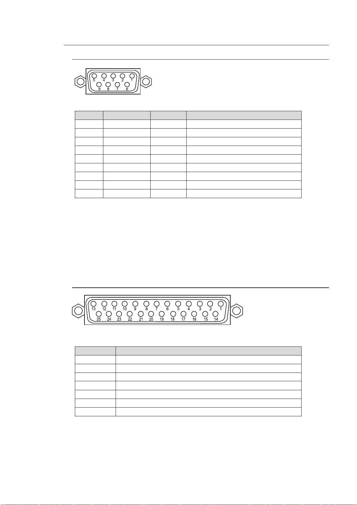
2-4. Interfaces
Pin No.
Signal Name
In/Out
Description
1
FG Frame ground
2
R-
In
Receive data (-)
3
T+
Out
Transmit data (+)
4
SG Signal ground
5
NC Not used
6
SG Signal ground
7
R+
In
Receive data (+)
8
T-
Out
Transmit data (-)
9
FG Frame ground
Pin No.
Description
1
BKGD AUTO TRANS (input) (default setting)
2
KEY1 AUTO TRANS (input) (default setting)
3
KEY2 AUTO TRANS (input) (default setting)
4
DSK1 AUTO TRANS (input) (default setting)
5
DSK2 AUTO TRANS (input) (default setting)
6-24
Unassigned (default setting)
25
Frame ground
2-4-1. RS-422 Connector 1-2
Pin Assignment Table (9-pin D-sub ,female, with inch screws)
RS-422 ports are used for the following device connections. See the related chapters to
configure the connections.
HVS-30RU: See section 20-6. "Remote Panel (HVS-30RU)."
Tally Units: See section 20-1-3. "Sending Tally Signals to Tally Units."
VTR/VDCP devices: See section 20-2. "VTR / VDCP Control."
Routers: See section 20-3. "Router Control."
Editor: See section 20-4 "Editor Control."
2-4-2. GPI IN/TALLY OUT Connector
Pin Assignment Table (25-pin D-sub, female, with inch screws)
See section 20-1-1. "GPI IN/TALLY OUT Connector" for more details.
21
Page 22
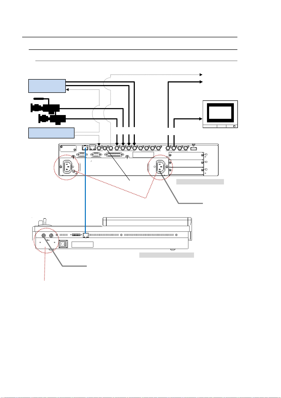
3. Connection
DC12V
1 2
POWER
OFF ON
MODE SW TO MU
HVS-XT100OU rear panel
Supplied LAN cable
75Ω-terminator
PGM(AUX1)
To AC power source
Video server,
VTR, etc.
TSG (REF signal)
HD/SD SDI
HD/SD SDI
Preview
(AUX2)
HVS-XT100 rear panel
REF OUT 112 3 4 5 6 7 8
2 3 4
A
B
C
REF IN
1 2
2
AC100-240V 50/60Hz INAC100-240V 50/60Hz IN
1
TO OU
LAN GENLOCK SDI INPUT
RS-422 GPI IN/TALLY OUT
HDMI OUTAUX
REF signal
To AC adaptor
Secure the power cord with the attached
AC cord clamp. (See the next page.)
Secure the power cord with the supplied
DC cord clamp. (See the next page.)
3-1. HVS-XT100 / XT100OU
3-1-1. Basic Configuration
See section 18-3. "Selecting a Reference Signal" for details on setting a reference signal.
See section 6-2. "Preview Set Up" for details on displaying preview image.
22
Page 23
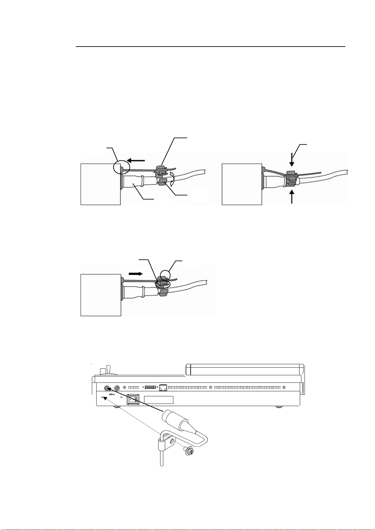
3-1-2. Installing the Power Cord Retaining Clamp
2)
4)
3)
5)
6)
1)
2)
DC12V
1 2
POWER
OFF ON
MODE SW TO MU
AC cord clamp
Installation
1) Wrap the retaining clamp around the AC cord (with the anchor of the ladder strap toward
the unit).
2) Insert the anchor into the hole next to the AC IN socket.
3) Lightly fasten the clamp around the AC cord.
4) Plug in the power cord.
5) Slide the clamp on the ladder strap toward the plug.
6) Fasten the clamp tightly.
7) Gently pull on the AC cord to ensure it is secured.
Uninstallation
1) Push the tab on the retaining up to unfasten the clamp.
2) Push the tab on the ladder strap up and slide the clamp back.
3) Unplug the AC cord.
DC Cord Clamp Installation
Insert the DC cord into the DC IN connector, then secure the cord with the DC cord clamp
attached to the hole as shown in the figure.
23
Page 24
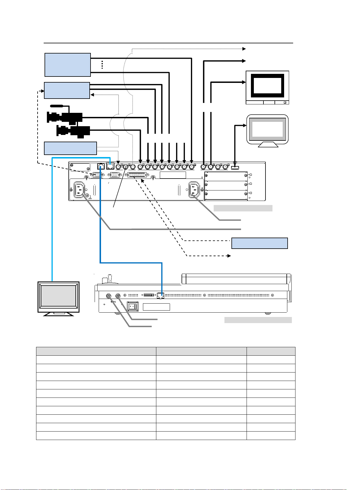
3-1-3. Optional Configuration
Device / Signal
Connection / Interface
Refer to sec.
Multiviewer output
SDI (BNC) or HDMI
13
GPI in/out, Tally out
GPI IN/TALLY OUT
20-1
Tally unit
RS-422
20-1-3
VTR
RS-422
20-2
Router
RS-422
20-3
Editor
RS-422 (with software option)
20-4
AUX bus control boxes (HVS-AUX8/16/32)
ARCNET LAN (optional)
20-5
Remote Panel (HVS-30RU)
RS-422
20-6
PC (Web browser control)
Ethernet
21
PC (Image transport)
Ethernet
12-4
GPI OUT
TALLY OUT
GPI Controller
Web-based control
Image file transfer
PC
Router
Multiview
(HDMI)
DC12V
1 2
POWER
OFF ON
MODE SW TO MU
HVS-XT100OU rear panel
Supplied LAN cable
75Ω-terminator
PGM(AUX1)
To AC power source
Video Server,
VTR, etc.
TSG (REF signal)
HD/SD SDI
Preview
(AUX2)
HVS-XT100 rear panel
REF OUT 112 3 4 5 6 7 8
2 3 4
A
B
C
REF IN
1 2
2
AC100-240V 50/60Hz INAC100-240V 50/60Hz IN
1
TO OU
LAN GENLOCK SDI INPUT
RS-422 GPI IN/TALLY OUT
HDMI OUTAUX
REF signal
HD/SD SDI
To AC power source
To AC adaptor
To AC adaptor
External Device Connections
24
Page 25
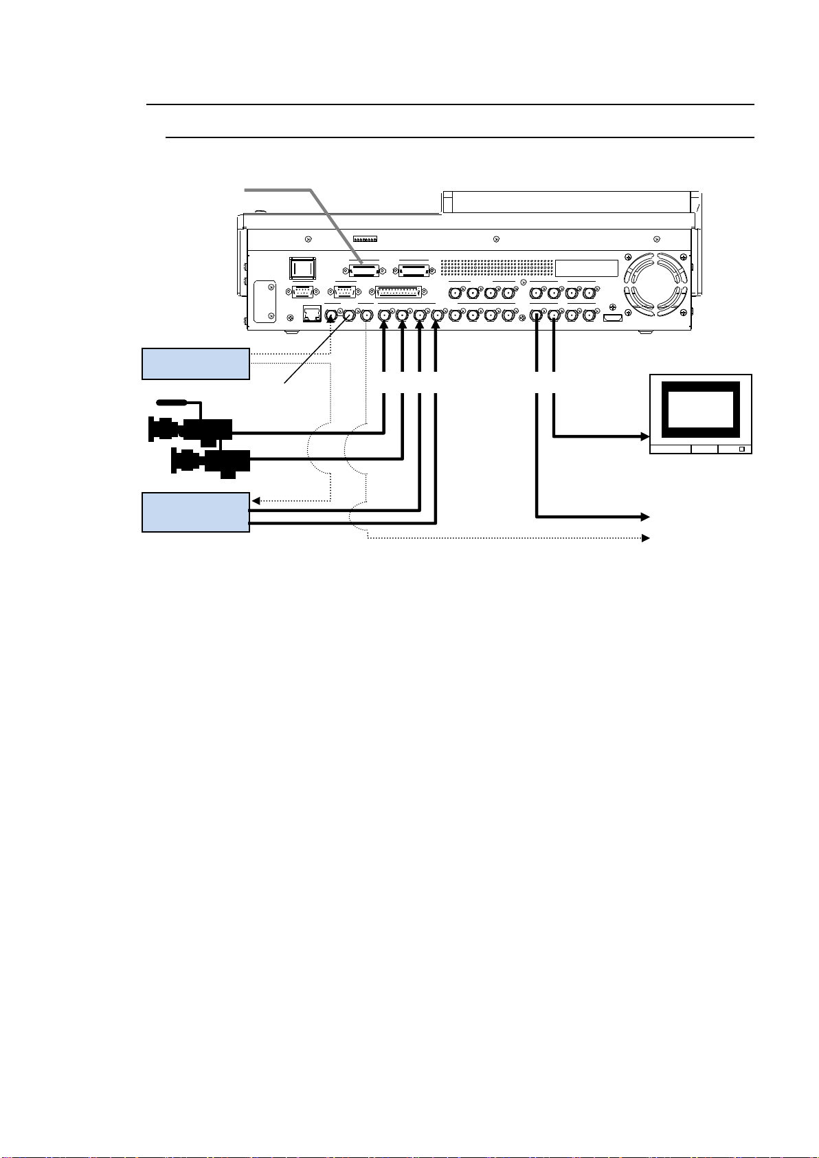
3-2. HVS-XT110
REF OUT 1 12 3 4 5 6 7 8 2 3 4REF IN
HDMI OUT
AUX
5 6 7 8
AUX
LAN
SDI INPUT
9 10 11 12
SDI INPUT
GPI IN/TA LLY OUT
DC12V IN
1 2
MODE SW
POWER
OFF ON
GENLOCK
RS-422
1 2
75Ω terminator
PGM(AUX1)
AC adaptor
Video Server,
VTR, etc.
TSG (reference)
HD/SD SDI
REF signal
HD/SD SDI
Preview
(AUX2)
3-2-1. Basic Configuration
See section 18-3. "Selecting a Reference Signal" for details on setting a reference signal.
See section 6-2. "Preview Set Up" for details on displaying preview image.
25
Page 26
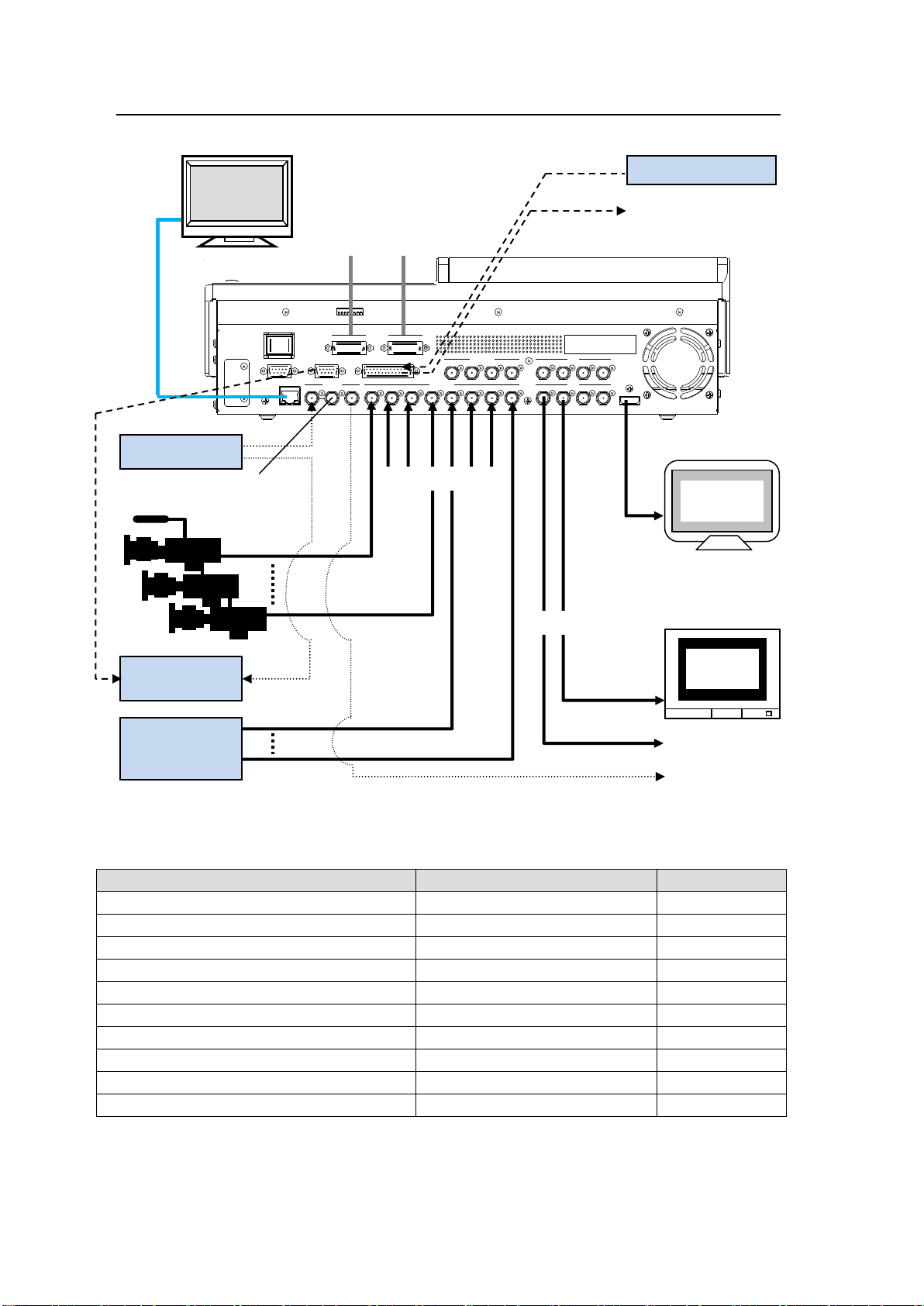
3-2-2. Optional Configuration
Device / Signal
Connection / Interface
Refer to sec.
Multiviewer output
SDI (BNC) or HDMI
13
GPI in/out, Tally out
GPI IN/TALLY OUT
20-1
Tally unit
RS-422
20-1-3
VTR
RS-422
20-2
Router
RS-422
20-3
Editor
RS-422 (with software option)
20-4
AUX bus control boxes (HVS-AUX8/16/32)
ARCNET LAN (optional)
20-5
Remote Panel (HVS-30RU)
RS-422
20-6
PC (Web browser control)
Ethernet
21
PC (Image transport)
Ethernet
12-4
REF OUT 1 12 3 4 5 6 7 8 2 3 4REF IN
HDMI OUT
AUX
5 6 7 8
AUX
LAN
GENLOCK SDI INPUT
9 10 11 12
SDI INPUT
EDITOR RS-422 GPI IN/TALLY OUT
DC12V IN
1 2
MODE SWPOWER
OFF ON
AC
adaptor
GPI OUT
TALLY OUT
GPI Controller
AC
adaptor
75Ω-terminator
PGM(AUX1)
Video Server,
VTR, etc.
TSG (REF signal)
HD/SD SDI
Preview
(AUX2)
Multiview
(HDMI)
Router
Web-based control
Image file transfer
REF signal
HD/SD SDI
PC
External Device Connections
26
Page 27

3-3. Power ON
IMPORTANT
Do not plug in or out of AC adaptors or power cords while the switcher is powered on.
IMPORTANT
Do not plug in or out of AC adaptors or power cords while the switcher is powered on.
Before powering on the system, verify that all system connections have been properly made
according to the previous sections.
3-3-1. HVS-XT100/XT100OU
(1) Use the supplied LAN cable with the HVS-XT100OU to connect the TO OU connector on
the HVS-XT100 rear panel and the TO MU connector on the HVS-XT100OU rear panel.
(2) Use the supplied power cord to supply AC power to the HVS-XT100. Secure the power
cord with the attached cord clamp.
See section 3-1-2. "Installing the Power Cord Retaining Clamp."
(3) Use the supplied AC adaptor and power cord to supply power to the HVS-XT100OU.
Secure the DC cord to the HVS-XT100OU rear panel with the supplied cord clamp.
See section 3-1-2. "Installing the Power Cord Retaining Clamp."
(4) Turn on the power switches on the HVS-XT100 front panel and HVS-XT100OU rear
panel.
3-3-2. HVS-XT110
Supply DC power to the control panel using the provided AC adaptor and power cord and
turn on the power switch located on the rear panel of the switcher. If redundant power is
supplied using the HVS-XT110PSM, the power switch on both power units will turn on.
27
Page 28
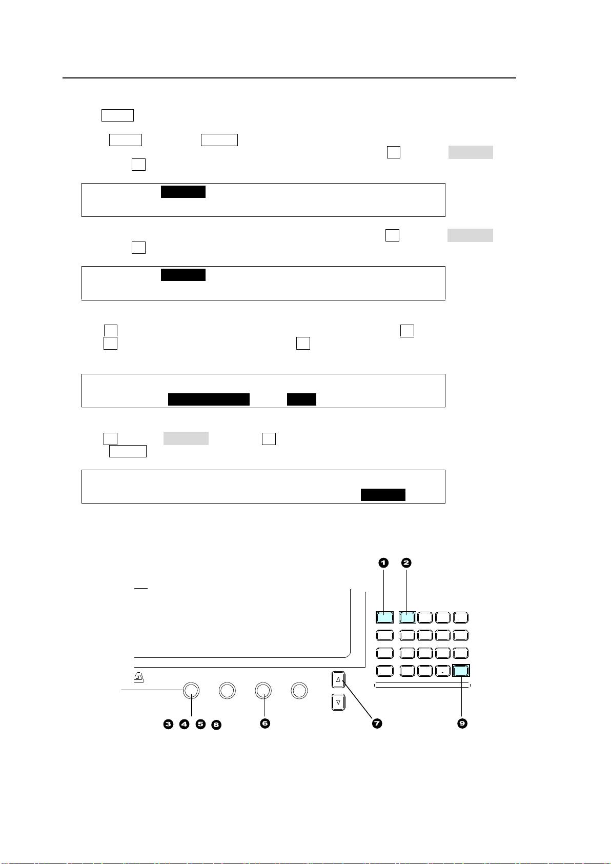
3-4. System Signal Format Selection at Initial Use
SETUP :>SYSTEM >INPUT >OUTPUT >PANEL
MENU :>GPI/TLY >FUNCTION>EXT I/F >STATUS
SETUP :>FORMAT >REF I/O >ARCNET >ETHERNET
SYSTEM :>RS-422 >TIME >INIT >REBOOT
SYSTEM : FORMAT :ASPECT :SW TMNG: 1/1
FORMAT : =1080/59.94i : =16:9 : =ODD :
SETUP :>FORMAT >REF I/O >ARCNET >ETHERNET
SYSTEM :>RS-422 >TIME >INIT >REBOOT
DIGITAL VIDEO SWITCHER
F1 F2 F3 F4
PAGE
MENU ATTACH
DIRECT
PATT
DETACH
SETUP
KEY1
8 9
4 5 6
STILL MATT FILE
KEY2 DSK1 DSK2
EVENT
MACRO
1 2 3
0
CLEAR
RECALL STORE
ENTER
CK EFFECT
TRANS RATE WIPE
SELECT/KEYPAD
±
7
F1-F4
When first switching your unit on, select a signal format as shown below.
(1) The MENU button in the SELECT/KEYPAD block at the right of the menu display should
blink when powered ON.
(2) Press MENU, then press SETUP.
(3) The SETUP menu top page appears in the menu display. Turn F1 to select SYSTEM and
then press F1.
(4) The [SETUP - SYSTEM] menu as shown below appears. Turn F1 to select FORMAT and
then press F1.
(5) The [SETUP - SYSTEM - FORMAT] menu as shown below appears.
Turn F1 to select the signal format used in the switcher, then press F1.
(6) Turn F3 to select the aspect ratio, then press F3.
For example, to use HD-SDI signals (1080i, 59.94Hz), set as shown below.
(7) Press the page up button to return to the [SETUP - SYSTEM] menu.
(8) Turn F1 to select REBOOT and press F1.
(9) Press ENTER in the SELECT/KEYPAD block to reboot the switcher
After restarting the switcher, the selected format and aspect are applied.
28
Page 29
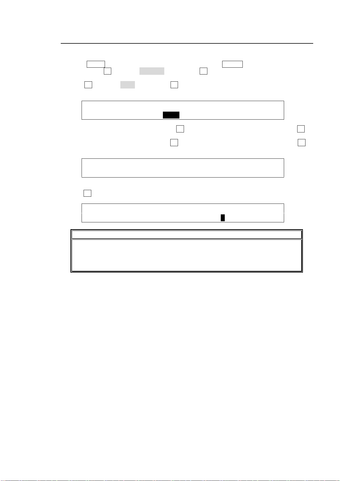
3-5. Setting Date, Time and Time Zone at Initial Use
SETUP :>FORMAT >REF I/O >ARCNET >ETHERNET
SYSTEM :>RS-422 >TIME >INIT >REBOOT
SYSTEM : DATE(mm/dd/yy):TIME[10:20:10] : 1/4
TIME : =SEP/01/13 : =10:20:20 :
SYSTEM :1st CHK:SUMMER :TIME ZONE : 2/4
TIME : =OFF : =OFF : =UTC[ 9:00] :
IMPORTANT
The date and time information are used for the multiviewer clock and when backing up
image or setting files. Note that date and time information may be lost if the switcher is
powered OFF for more than 100 hours (or less if it is not fully charged). In such case,
reset the date and time.
When first switching your unit on, set the date, time and time zone as shown below.
(1) Press MENU in the SELECT/KEYPAD block, then press SETUP to display the SETUP top
menu. Turn F1 to select SYSTEM, then press F1 or the page down button to open the
[SETUP - SYSTEM] menu.
(2) Turn F1 to select TIME, then press F1 or the page down button to open the [SETUP -
SYSTEM - TIME] menu.
(3) If you need to change the date, press F1 to select Month, Day or Year, then turn F1 to
change the setting.
(4) If you need to change the time, press F3 to select Hour, Minute or Second, then turn F3 to
change the setting.
(5) Press the page down button to open PAGE 2.
(6) Turn F3 to set the time zone offset value.
29
Page 30
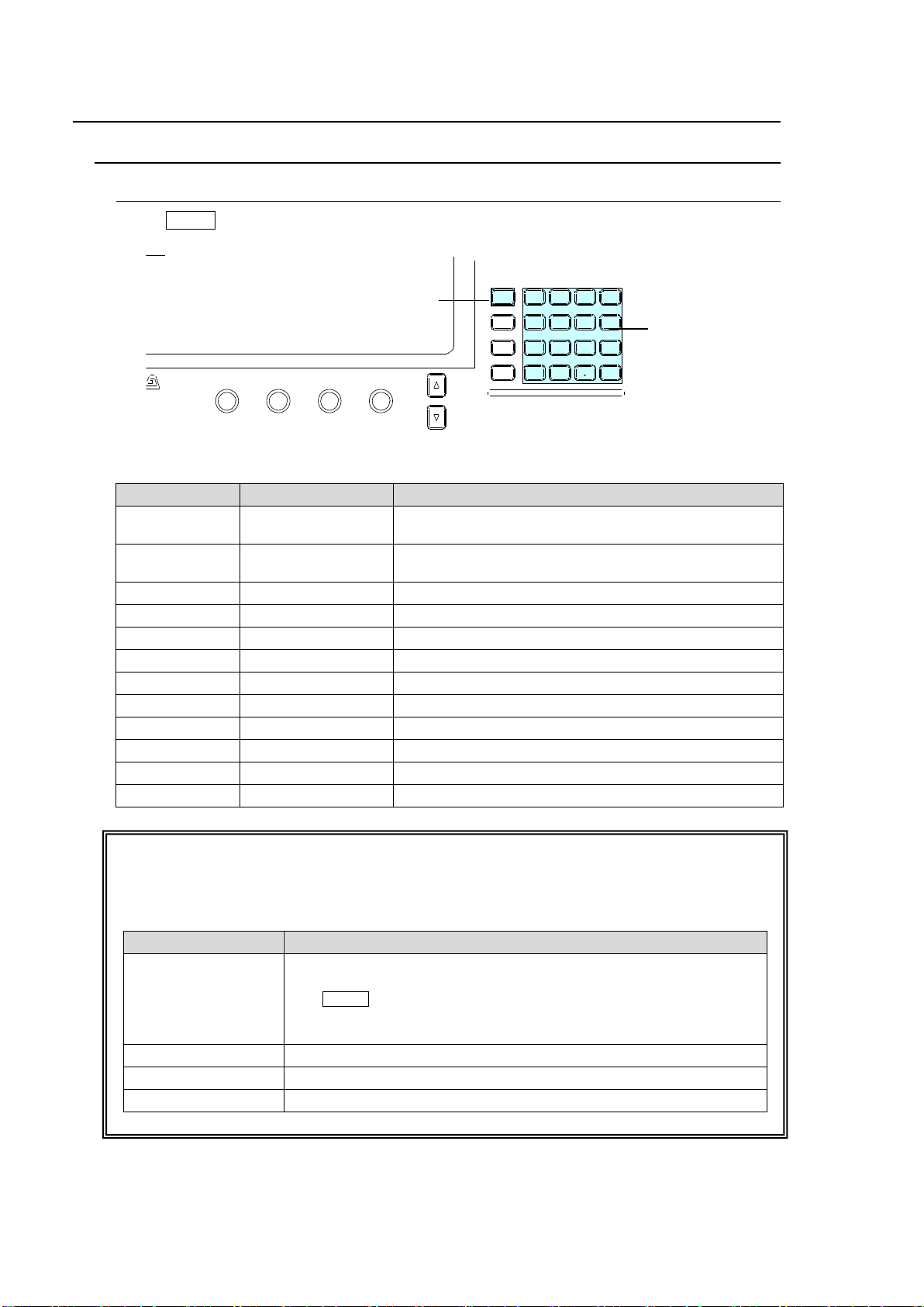
4. Menu Operation
Button
Accessed menu
Menu Description
SETUP
SETUP MENU
Accesses menu for the setups of system, panel, video
input, video output and external interface settings.
STILL
STILL STORE
Accesses menu for operations with involving still
images and video clips.
MATT
MATT COLOR
Accesses menu for matte color.
FILE
FILE TOP
Accesses menu for file operations using a USB.
KEY1
KEY1 SETUP
Accesses menu for KEY1 settings.
KEY2
KEY2 SETUP
Accesses menu for KEY2 settings.
DSK1
DSK1 SETUP
Accesses menu for DSK1 settings.
DSK2
DSK2 SETUP
Accesses menu for DSK2 settings.
CK
CHR KEY SETUP
Accesses menu for chromakey settings.
EFFECT
EFFECT SETUP
Accesses menu for sub effect channel settings.
TRANS RATE
TRANS RATE
Accesses menu for transition settings.
WIPE
WIPE
Accesses menu for WIPE pattern modification.
Mode Button
Function
MENU
Changes the keypad to menu access buttons. Pressing a button in
the keypad displays the associated menu.
The MENU control button blinks if a parameter has changed and
requires rebooting. In such case, reboot the switcher.
See section 19-1. "Rebooting System."
DIRECT PATT
Changes the keypad to direct pattern selection buttons.
EVENT
Changes the keypad to event memory buttons.
MACRO
Changes the keypad to macro control and memory buttons
DIGITAL VIDEO SWITCHER
F1 F2 F3 F4
PAGE
MENU ATTA CH
DIRECT
PATT
DETACH
SETUP
KEY1
8 9
4 5 6
STILL MATT FI LE
KEY2 DSK1 DSK2
EVENT
MACRO
1 2 3
0
CLEAR
RECALL STORE
ENTER
CK EFFECT
TRANS RATE WIPE
SELECT/KEYPAD
±
7
KEYPAD block
MENU button
4-1. How to Access Menus
4-1-1. Menu Access Buttons
Press MENU on the left side of the SELECT/KEYPAD block, then press the buttons on the
keypad to access menus.
KEYPAD Block
SELECT / keypad Block
Four modes buttons on the left side of the SELECT/KEYPAD block change the keypad mode
as shown in the table below.
30
Page 31
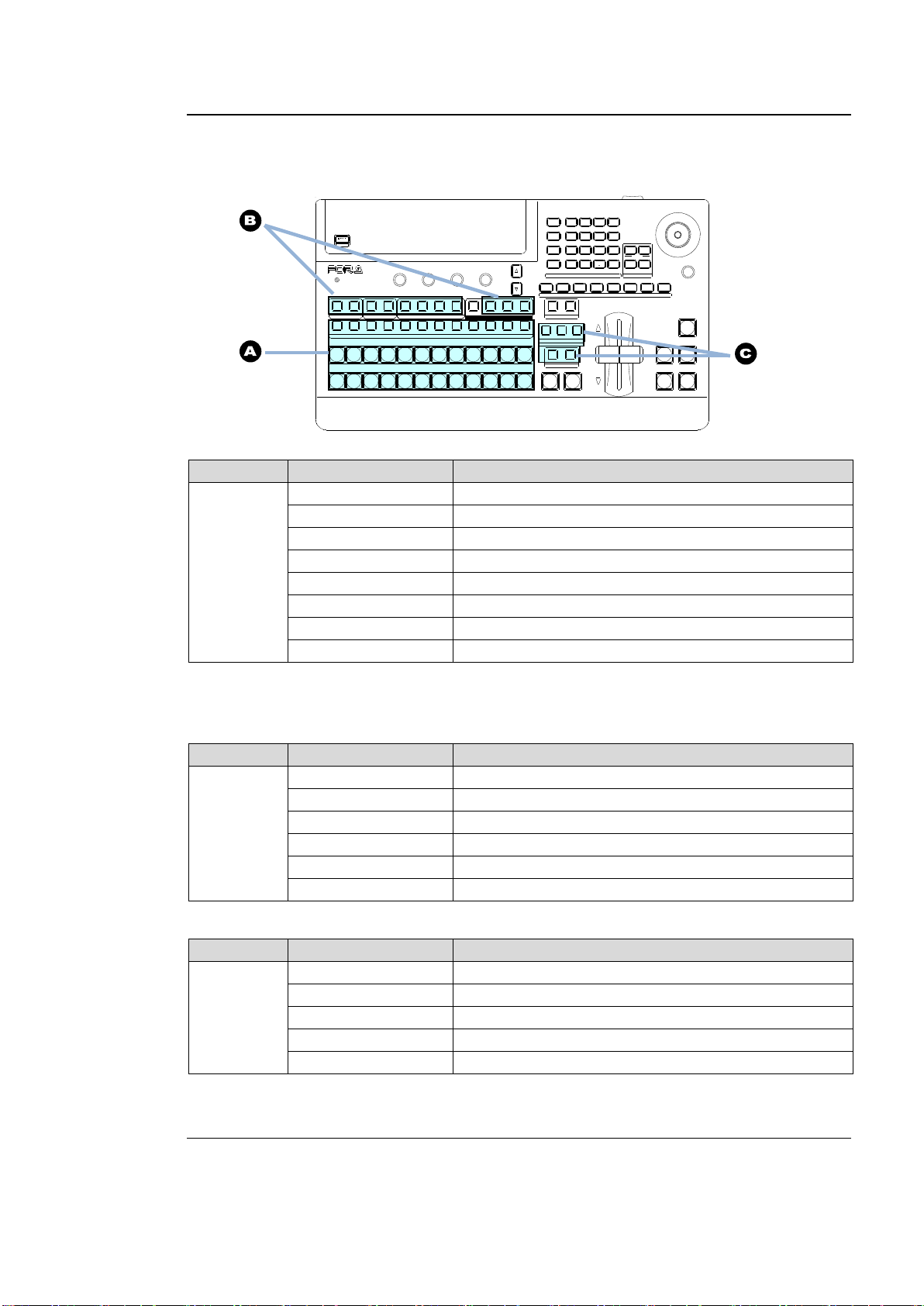
4-1-2. Other Menu Access Buttons
See Fig.
Button
Accessed Menu (Page)
A
MATT1-2
[MATT] menu
STL1-2
[STILL] menu
STK1-2
[STILL] menu
CKFIL
[CHR KEY - SETUP] menu
CKKEY
[CHR KEY - SETUP] menu
CB
[SETUP - INPUT - COLRBAR] menu
EFF1-2
[EFFECT(1, 2)] menu
SHIFT
[SETUP-INPUT-ASSIGN](3/3) menu
Note that the buttons in this table represent the bus buttons assigned to MATT1, MATT2, STILL1, STILL2,
and other signals respectively on the PGM/PST and KEY/AUX bus blocks. (Refer to section 5. "Video
Sources.")
See Fig.
Button
Accessed Menu (Page)
B
KEY1, KEY2
[KEY (1, 2)- SETUP] menu
DSK1, DSK2
[DSK (1, 2)- SETUP] menu
AUX1 to AUX4
[SETUP - OUTPUT - OUT XPT](1/3) menu
PREV
[SET UP - OUTPUT - CLN/PREV] PREV menu
CLEAN
[SET UP - OUTPUT - CLN/PREV] CLEAN menu
MV
[SETUP - OUTPUT - MV] menu
See Fig.
Button
Accessed Menu (Page)
C
BKGD
[TRANS](1/6) menu
KEY1
[TRANS](2/6) menu
KEY2
[TRANS](3/6) menu
MIX
[TRANS](1/6) menu
WIPE
[TRANS](1/6) menu
USB MEMORY
DIGITAL VIDEO SWITCHER
HVS-
XT
SIZE
(PUSH to DEF)
1 2 3 4 5 6 7 8
USER BUTTON
REV NOR/REV
DIRECTION
BLACK
TRANS
BKGD KEY1 KEY2
NEXT TRANSITION
MIX WIPE
KEY1 KEY2
TRANSITION TYPE
AUTO CUT DSK1 DSK2
ALARM
F1 F2 F3 F4
PAGE
1 1 1
1
2 2 2 3 4
2 3 4 5 6 7 8 9 10 11 12
KEYER DSK AUX
KEY/AUX
PGM PREV CLEAN MV
PGM
PST
1 2 3 4 5 6 7 8 9 10 11 12
MENU ATTACH
DIRECT
PATT
DETACH
SETUP
KEY1
POSITION
POS ROT
2D DVE
WIPE
POS
MENU
JOYSTICK
8 9
4 5 6
STILL MATT FILE
KEY2 DSK1 DSK2
EVENT
MACRO
1 2 3
0
CLEAR
RECALL STORE
ENTER
CK EFFECT
TRANS RATE WIPE
SELECT/KEYP AD
±
7
Asidefrom the menu buttons, the related menu pages can be displayed by pressing (buttons
in C) or Double-pressing (quickly pressing twice) (buttons in A and B) specific buttons as
shown in the tables below.
PGM/PST and KEY/AUX blocks
BUS SELECT and KEY/AUX blocks
Transition block
4-1-3. USER Buttons (Menu Shortcut)
User buttons can be assigned to specific menu pages and used as menu shortcuts.
See section 14. "USER Buttons" for details.
31
Page 32
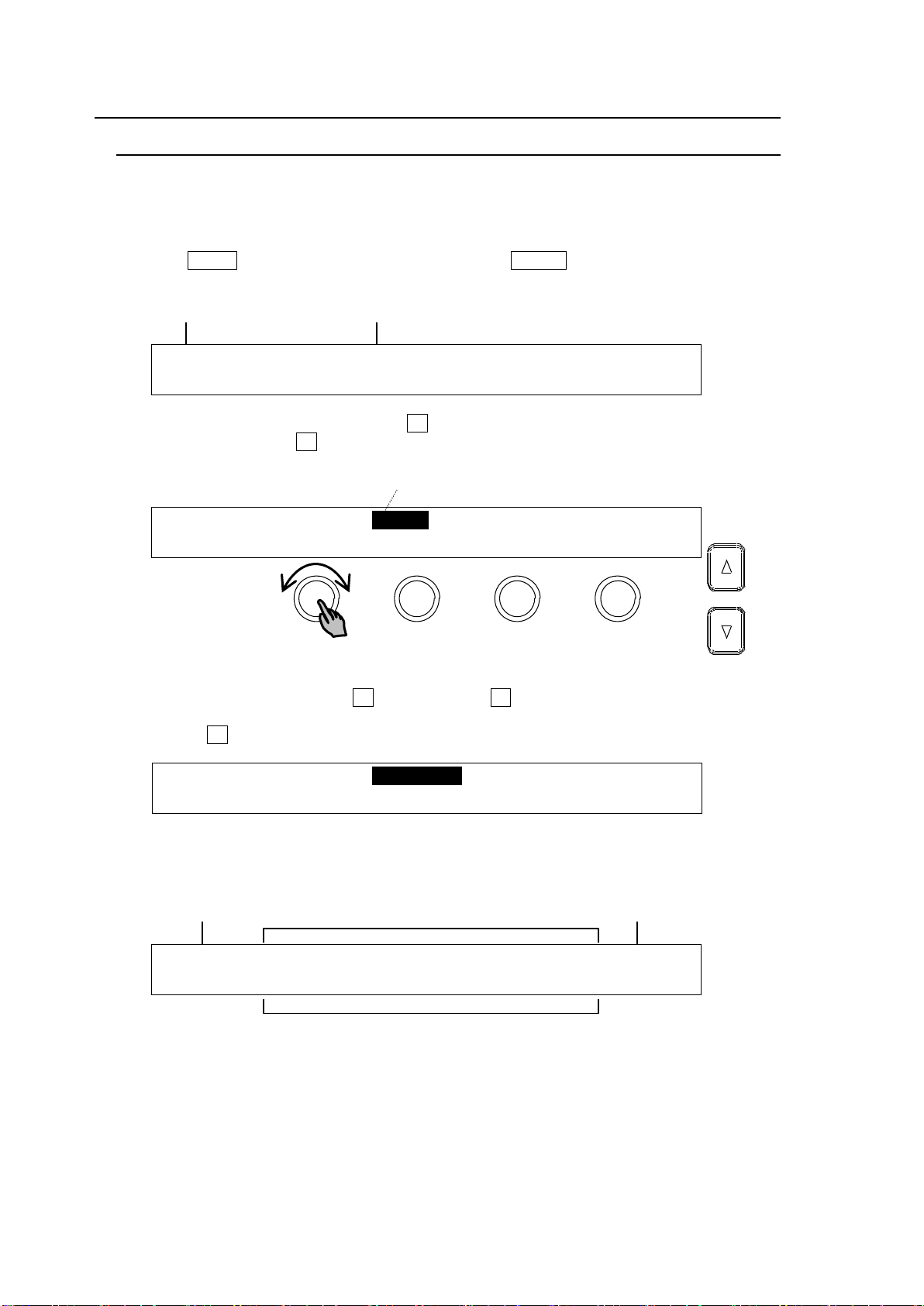
4-2. How to Set Values
SETUP :>SYSTEM >INPUT >OUTPUT >PANEL
MENU :>GPI/TLY >FUNCTION>EXT I/F >STATUS
SETUP :>SYSTEM >INPUT >OUTPUT >PANEL
MENU :>GPI/TLY >FUNCTION>EXT I/F >STATUS
SETUP :>SIGNAL >PROC AMP>RENAME >ASSIGN
INPUT :>COLORBAR
INPUT :SELECT :LumGain: Setup :ENABLE : 1/3
PROC AMP: =IN04 : =10.00: =0 : =ON :
Menu title
Submenu title
The current selection is shown in reverse video.
Menu title
Parameters
Page / Total page
Values
F1 F2 F3 F4
PAGE
4-2-1. Displaying Parameters
See section 4-1. "How to Access Menus" to display a desired menu. If a menu has multiple
submenus such as the SETUP menu, navigate to submenus following the procedure below.
Menu Navigation (Example for the SETUP menu)
(1) Press MENU in the SELECT/KEYPAD block, then SETUP to display the SETUP menu.
The SETUP menu top page will then appear on the display, as shown below.
(2) Select a submenu to open by turning F1 (The INPUT submenu is selected in the example
below.) Then press F1 or the page down button to the right to open the selected
submenu.
(3)The [SETUP - INPUT] menu then opens. The [SETUP - INPUT] menu also has submenus.
Select a submenu by turning F1 and then press F1 or the page down button to open the
submenu. A ">" in front of menu items indicates that a detail submenu can be accessed by
pressing F1.
(4) The [SETUP - INPUT - PROC AMP] menu is displayed as shown below. Now users can
change the parameter values.
32
Page 33
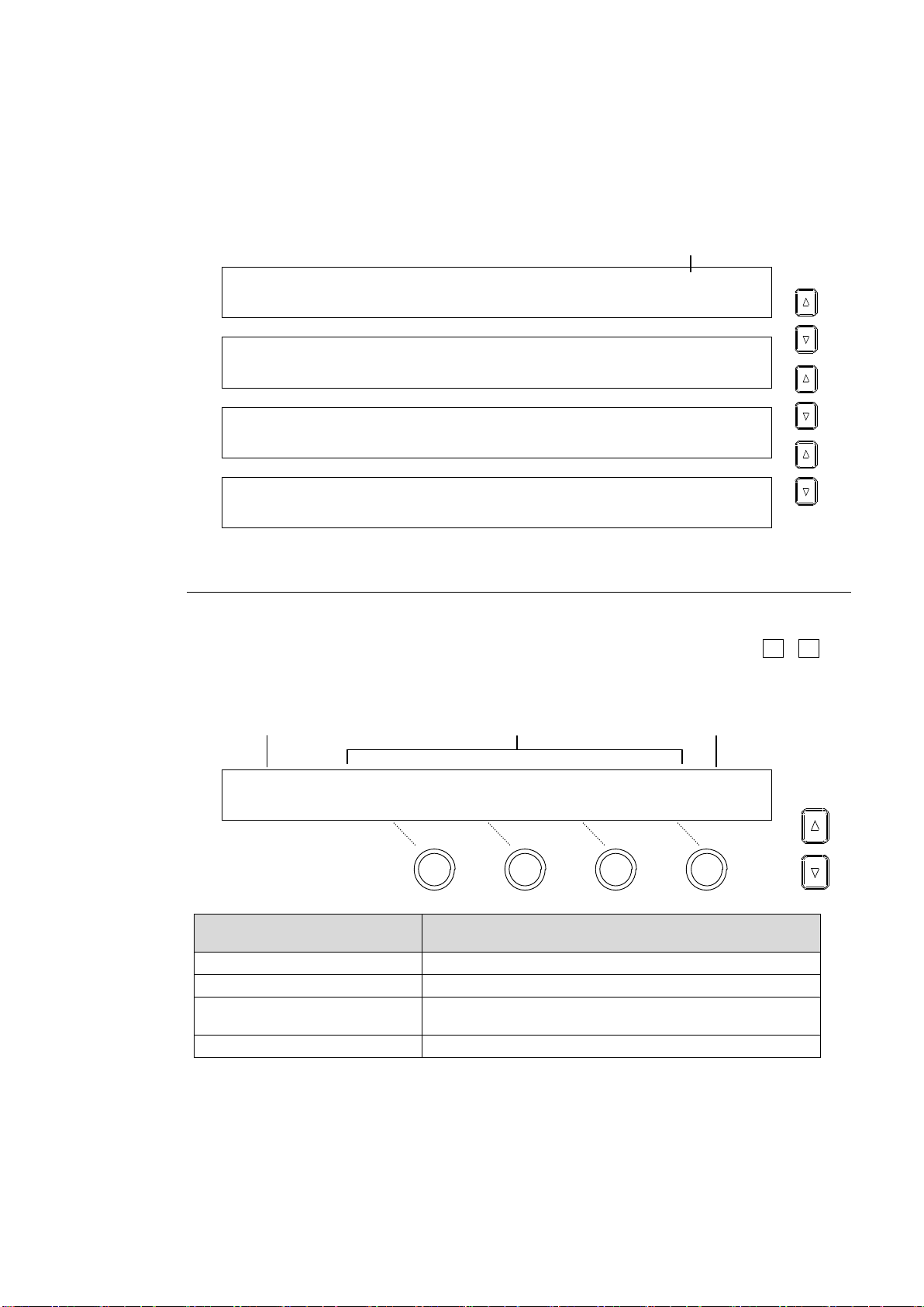
Page Navigation
INPUT :SELECT :LumGain: Setup :ENABLE : 1/3
PROC AMP: =IN04 : =10.00: =0 : =ON :
INPUT :SELECT :ChmGain: Hue :ENABLE : 2/3
PROC AMP: =IN04 : =10.00: =0 : =ON :
INPUT :WHT-Lv :BLK-Lv :Chroma : : 3/3
CLIP : =1019 : =-70 : =1110 : :
SETUP :>SIGNAL >PROC AMP>RENAME >ASSIGN
INPUT :>COLORBAR
INPUT :SELECT :FORMAT :RESIZE : FS : 1/4
SIGNAL : =IN01 : =AUTO : =--- : =ON :
Menu Control Push-buttons
(F1 to F4)
Description
Turn clockwise
Increases value.
Turn counter-clockwise
Decreases value.
Press and hold down
at least 1 sec.
Resets the parameter to its default value.
Turn while pressing
Quickly increases/decreases value.
Page no. / Total page
PAGE
PAGE
PAGE
Parameters (First line)
Settings (Second line)
Title
Page/Total page
F1 F2 F3 F4
PAGE
PAGE
As shown in the example below, the [SETUP - INPUT - PROC AMP] submenu spreads
across three pages. When first accessed, page 1 of 3 will be displayed. To go to page 2,
simply press the page down button. Pressing the page up button returns you to page 1.
Pressing the page up button when located on the first page brings you up one level in the
menus. The same happens when pressing the page down button when located on the last
page of a menu.
4-2-2. Changing Settings or Values Using F1 to F4
Once parameters appear in the display window, data is displayed over 2 lines. A maximum of
four parameters can be displayed at a time. An "=" or ">" in front of a value indicates that it is
possible to change a parameter setting by turning a menu control push-button (F1 - F4), or
trigger an action by pressing it.
System Parameters Requiring Confirmation
For some system parameters, you will have to press menu control push-buttons after
changing parameter settings by turning menu control push-buttons. This prevents users from
making mistakes when important system settings are changed.
33
Page 34
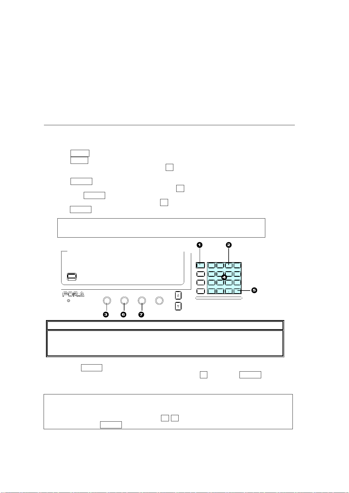
Parameters with the sign ">"
MATT1 : BUS MATT1 COLOR :RECALL : 1/4
COLOR :S=50.0 L=80.2 H=125.5: >GREEN:
IMPORTANT
When pressing a push-button, press down lightly and release it within 1 sec. Note that
if you press and hold a control button for more than 1 sec., the associated settings will
return to their default value and a beep will sound.
KEYPAD Operation in Numeric Input mode
The keypad can operate in multiple modes such as Menu, Direct Pattern, Macro and Event
using the mode buttons on the left side of the keypad. To input menu settings using the
keypad, display a desired parameter, press the menu control push-button located just
below the parameter in the menu dsiplay (F1-F4), enter the value using the numeric
keypad, then press ENTER on the KEYPAD.
USB MEMORY
DIGITAL VIDEO SWITCHER
ALARM
F1 F2 F3 F4
PAGE
MENU ATTACH
DIRECT
PATT
DETACH
SETUP
KEY1
8 9
4 5 6
STILL MATT FILE
KEY2 DSK1 DSK2
EVENT
MACRO
1 2 3
0
CLEAR
RECALL STORE
ENTER
CK EFFECT
TRANS RATE WIPE
SELECT/KEYPAD
±
7
Parameters with ">" sign in front of them are executable by pushing the relevant menu
control push-button. For example, pressing a menu control push-button initializes menus,
stores/recalls still images, clips or setting files.
See section 4-3. "How to Return Settings to Default."
See section 12. "Still and Clip Store."
See section 17. "File Operation."
The relevant menu control push-button should be pressed to apply a preset color.
See section 5-9. "Bus Matte")
4-2-3. Changing Settings or Values Using the Numeric Keypad
Users can also use the keypad to input numerical settings to a menu. A procedure example
for changing the matte color by using the keypad is as follows.
(1) Press MENU in the SELECT/KEYPAD block.
(2) Press MATT to display the [MATT COLOR] menu.
(3) To change the S (Saturation) item, press F1.
(4) Input a new setting from the keypad.
(5) Press ENTER to confirm the setting.
(6) To change the L (Luminance) setting, press F2, input the new setting from the keypad,
then press ENTER.
(7) To change the H (Hue) setting, press F3, input the new setting from the keypad, then
press ENTER.
Pressing CLEAR cancels the changes just made.
To enter a negative number, enter the number, press ± then press ENTER.
34
Page 35
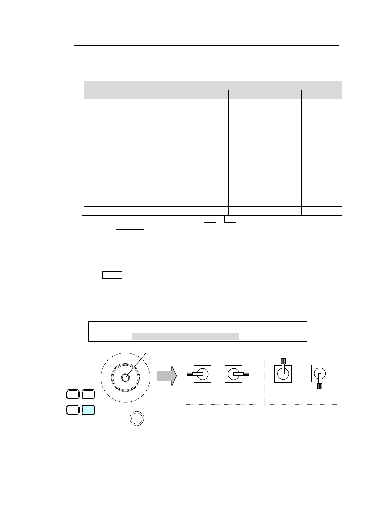
4-2-4. Changing Settings or Values Using the Joystick
Menu
Parameter
Menu item
X-axis
Y-axis
SIZE
MATT1
BUS MATT1 COLOR
SAT
LUM
HUE
MATT2
BUS MATT2 COLOR1-2
SAT
LUM
HUE
KEY1, KEY2
DSK1, DSK2
BORDER COLOR
SAT
LUM
HUE
POSITION SIZE
(*1)
X Y SIZE
LOCAL ROTATION
(*1)
X Y Z
CENTER POSITION
(*1)
X Y Z
INSERT MATT COLOR
SAT
LUM
HUE
KEY1, KEY2
KEY EDGE COLOR
SAT
LUM
HUE
WIPE (0 to 99)
BORDER COLOR
SAT
LUM
HUE
POSITION ANGLE
(*2)
POS-X
POS-Y
ANGLE
WIPE (100 to 137)
BORDER COLOR
SAT
LUM
HUE
POSITION SIZE
(*2)
POS-X
POS-Y
SIZE
CHR KEY
AUTO CK
POS-X
POS-Y
SELECT
(*1) To open the associated menu, Double-press POS or ROT in the Joystick section.
See section 9-8." DVE Effects on KEY/DSK .")
(*2) Pressing WIPE POS on the Joystick block allows you to control parameters via the joystick without
opening the menu.
WIPE : BORDER COLOR :RECALL : 2/2
BORDER :S=66.3 L=5.4 H=3.5 : >BLUE :
Move down
(-Y)
Move up
(+Y)
Move left
(-X)
Move right
(+X)
Joystick operation
Joystick
SIZE control (to turn)
SIZE
(PUSH to DEF)
POSITION
POS ROT
2D DVE
WIPE
POS
MENU
JOYS TICK
Users can also use the joystick to set position, size and color settings to specific parameters.
Menu pages controllable from the JOYSTICK block are shown in the table below.
Controllable Parameters
How to Use the Joystick
Users can simultaneously perform up to three item settings using the joystick as below.
(1) Open a menu page you want to set.
(2) Press MENU in the joystick block.
(3) Move the joystick to the desired direction to change three items simultaneously.
X-axis Moves the joystick left and right (for S item above).
Y-axis Moves the joystick up and down (for L item above).
Z-axis Turn SIZE clockwise or counterclockwise
(for H item above).
FINE Control (using a user button)
Assign "JOYSTICK -FINE ENABLE" to a user button, then press the button. The button will
turn on to allow the user to have finecontrol over the joystick.
See section 14. "USER Buttons."
35
Page 36
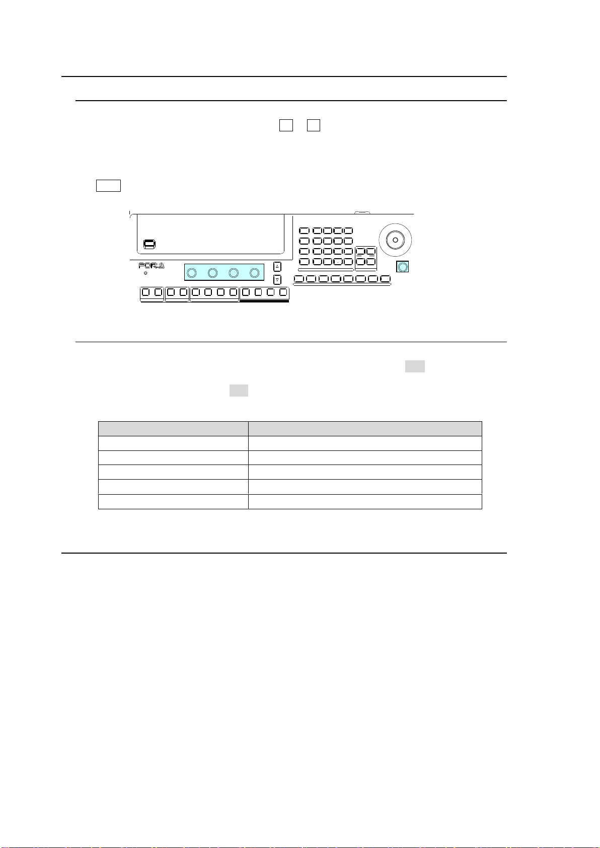
4-3. How to Return Settings to Default
Menu where INIT included
Menus to be returned to default settings
[SETUP - SYSTEM] menu
See section 19-2. "System Initialization."
[WIPE - MODIFY] menu
Each submenu in the [WIPE MODIFY] menu.
[KEY - SETUP] menu
Each submenu in a [KEY - SETUP] menu.
[CHR KEY - SETUP] menu
The [CHR KEY - SETUP] menu
[EFFECT - SETUP] menu
Each submenu in an [EFFECT - SETUP] menu
USB MEMORY
DIGITAL VIDEO SWITCHER HVS-
XT
SIZE
(PUSH to DEF)
1 2 3 4 5 6 7 8
USER B UTTON
ALARM
F1 F2 F3 F4
PAGE
1 1 12 2 2 3 4
KEYER DSK AUX
PGM PREV CLEAN MV
MENU ATTA CH
DIRECT
PATT
DETACH
SETUP
KEY1
POSITION
POS ROT
2D DVE
WIPE
POS
MENU
JOYSTICK
8 9
4 5 6
STILL MATT FILE
KEY2 DSK1 DSK2
EVENT
MACRO
1 2 3
0
CLEAR
RECALL STORE
ENTER
CK EFFECT
TRANS RATE WI PE
SELECT/KEYPAD
±
7
4-3-1. Returning Parameters to Default
Pressing and holding down Control Push-buttons
Press and hold the control push-button (F1 - F4) below each parameter to return the
resoectuve settings to their factory default.
Briefly pressing the DEF button
If you need to reset parameters that can be set by the joystick, display parameters and press
the SIZE control (PUSH TO DEF). The selected parameters will simultaneously reset to
factory default.
4-3-2. Returning Menus to Default
Using INIT parameters
Some menus have an INIT parameter in the menu top page. Selecting INIT and pressing the
control push-button returns all parameters in the menu to their default settings. Turn the
associated push-button to select ALL or a category you want to return to default if INIT can be
set, then press the push-button to reset the parameters.
4-4. How to Back up Settings
One of the following three operations allows users to back up and load panel settings
automatically at startup. Any of the three operations is recommended after changing menu
settings.
Rebooting (Be sure to reboot the switcher instead of turning the power off then on.)
See section 19-1. "Rebooting System."
Moving to the top page in the SETUP menu.
Saving / loading an event.
Background and key settings can be automatically loaded to the panel at startup.
See section 15-6. "Loading an Event at Start-up" for details.
36
Page 37
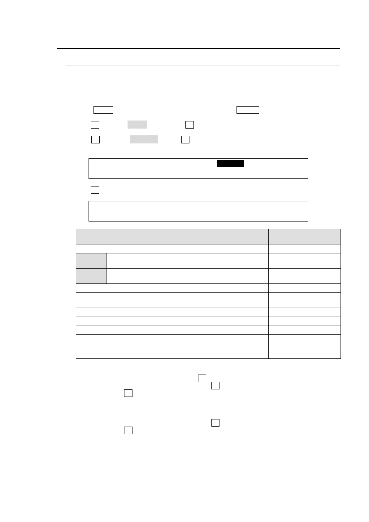
5. Video Sources
SETUP :>SIGNAL >PROC AMP>RENAME >ASSIGN
INPUT :>COLORBAR
INPUT :SELECT :SHORT : LONG NAME(MV) : 1/1
RENAME : =IN04 : =IN04 : =INPUT04 :
SELECT
SHORT
default setting
LONG NAME
default setting
(*1)
Signal description
BLACK
BLAK
BLACK
Black signal
XT100
IN01 to IN08
IN01 to IN08
INPUT01 to INPUT08
SDI video input to rear
connectors 1-8
XT110
IN01 to IN12
IN01 to IN12
INPUT01 to INPUT12
SDI video input to rear
connectors 1-12
STILL1, STILL2
STL1, STL 2
STILL1, STILL2
Still images 1-2
STILK1, STILK2
STK1, STK2
STILLKEY1,
STILLKEY2
Still KEYOUT (alpha
channel) images1 -2
CKFIL
CKFL
CK FILL
Chromakey fill signal
CKKEY
CKKY
CK KEY
Chromakey key signal
MATT1, MATT2
MAT1, MAT2
MATTE1, MATTE2
BUS matte color 1 and 2
SBEF1, SBEF2
EFF1, EFF2
SUB EFF1, SUB
EFF2
Sub effect channels
CLBAR
CLBR
COLOR BAR
Color bar
(*1) Long names are used for titles displayed on the multiviewer screen.
5-1. How to Assign User Names to Sources
Video inputs, Still1-2, StillKey1-2, Matte, Black and Color bar can be assigned user-specific
names, to make them easier to identify for operators. User names can be given to input signals,
internally generated black mattes and matte signals, and still pictures. Follow the procedure
below to name a signal source.
(1) Press MENU in the SELECT/KEYPAD block, then press SETUP to display the SETUP menu
top page.
(2) Turn F1 to select INPUT. Then press F1 or the page down button to display the [SETUP -
INPUT] menu.
(3) Turn F1 to select RENAME. Press F1 or the page down button to display the [SETUP -
INPUT - RENAME] menu.
(4) Turn F1 to select a signal under SELECT. (See the table below.)
(5) To change the short name of a signal, use F2 to assign a name up to 4 characters in length,
entering the characters one by one. First, press F2 to highlight a character. When the latter is
highlighted, turn F2 to change it. Alphanumeric characters and symbols (ASCII characters)
can be used for names.
(6) To change the long name of a signal, use F3 to assign a name up to 8 characters in length,
entering the characters one by one. First, press F3 to highlight a character. When the latter is
highlighted, turn F3 to change it. Alphanumeric characters and symbols (ASCII characters)
can be used for names.
37
Page 38
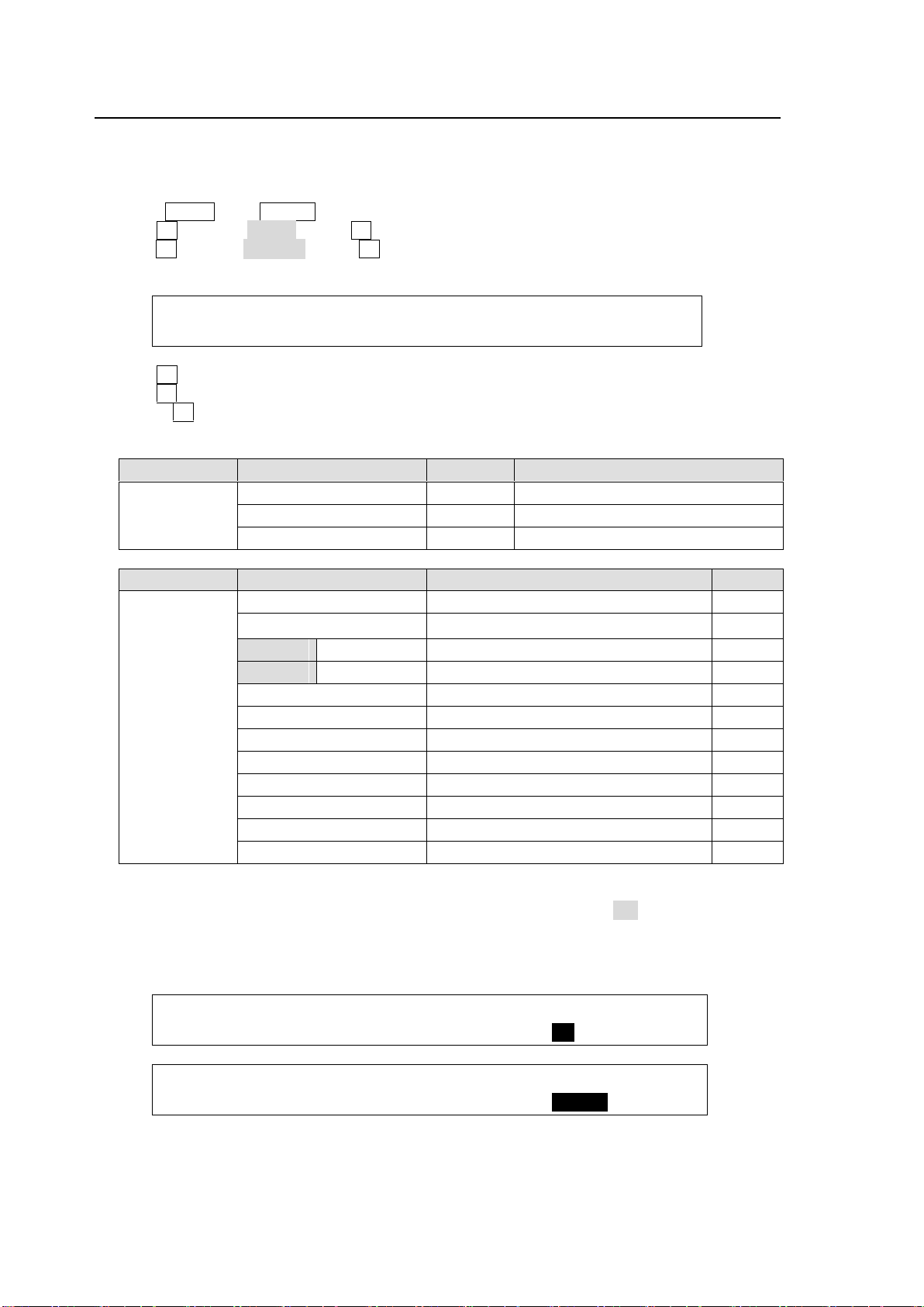
5-2. How to Assign Sources to Bus Buttons
INPUT :BUTTON : SIGNAL NAME :INHIBIT: 1/3
OU ASGN : =01 : =IN04 =IN04 : =OFF :
Submenu
Parameter
Default
Setting range
OU ASSIGN
BUTTON
1
1-20, sft1-sft20 (shifted buttons)
SIGNAL NAME
IN01
(See the table below)
INHIBIT
OFF
OFF, ON
BUTTON
SIGNAL setting
Description
Refer to
01 to 12,
sft01 to sft12
(shifted
buttons)
NONE
No signal assignment
BLACK
Black signal
XT100
IN01 to IN08
Video input to rear connectors 1-8
6
XT110
IN01 to IN12
Video input to rear connectors 1-12
6
STIL1, STIL2
Still images 1 and 2
12-1
STILK1, STILK2
Still key (alpha channel) images 1 and 2
12-1
CKFIL
Chromakey fill signal
10
CKKEY
Chromakey key signal
10
SBEF1, SBEF2
Sub Effect channels
MATT1, MATT2
BUS MATT Color 1 and 2
5-9
CLBAR
Internally generated color bar signal
SHIFT
Shift button function
7-3
INPUT :BUTTON : SIGNAL NAME :INHIBIT: 1/3
OU ASGN : =01 : =IN04 : =IN04 : =ON :
INPUT :SELECT : SHIFT : LINK :INHIBIT: 3/3
ASSIGN : =OU : =NORML: =--- : =ENABL:
Primary and optional video inputs, internally generated signals (black, mattes, etc.), and
captured stills can be freely assigned to bus buttons using the procedure below.
Signal-to-Button mappings are shared on the PGM/PST and KEY/AUX bus.
(1) Press MENU, then SETUP to display the SETUP menu top page.
(2) Turn F1 to select INPUT. Press F1 or the page down button to display the menu.
(3) Turn F1 to select ASSIGN. Press F1 or the page down button to display the [SETUP - INPUT
- ASSIGN] (1/3) menu.
(4) Turn F1 to select a bus button under BUTTON.
(5) Turn F2 to select the signal to be assigned under SIGNAL. Users can also select a signal by
turning F3 under NAME. SIGNAL and NAME are linked to each other.
See section 5-1. "How to Assign User Names to Sources" for more details.
To Disable Bus Button Operation
Users can inhibit operation of specific bus buttons. First, set INHIBIT to ON for a bus button on
PAGE 1, and the selected bus button on the PGM/PST is set to INHIBIT. Next, set INHIBIT to
ENABLE on PAGE 3 to enable the bus button inhibit function. Bus buttons, set to INHIBIT
cannot select signals. The INHIBIT setting has no effect on the KEY/AUX bus.
38
Page 39
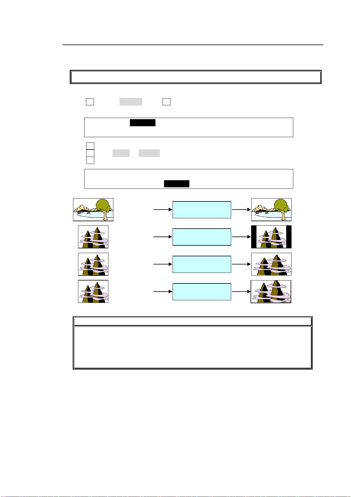
5-3. Resize Function
The Resize function is available on 4 inputs: IN05 to IN08.
SETUP :>SIGNAL >PROC AMP>RENAME >ASSIGN
INPUT :>COLORBAR
INPUT :SELECT :FORMAT :RESIZE : FS : 1/4
SIGNAL : =IN05 :=SD-SDI: =4:3 : =ON :
IMPORTANT
The Resize function is automatically enabled when SD signals are input to the
switcher in HD mode, and FORMAT in the [SETUP - INPUT - SIGNAL] menu is set to
SD-SDI. (Ensure the Resize function stays disabled if HD-SDI is set for FORMAT.)
The side panel color or image can be changed in 4:3 mode.
See section 5-5 "Changing the Side Panel Image."
IN01 (HD)
(1080/59.94i)
FORMAT (AUTO)
RESIZE (OFF)
IN05 (SD)
(525/59.94i)
FORMAT (SD-SDI)
RESIZE (4:3)
IN05 (SD)
(525/59.94i)
FORMAT (SD-SDI)
RESIZE (SQUEEZE)
IN05 (SD)
(525/59.94i)
FORMAT (SD-SDI)
RESIZE (LETTER)
A resize function allows users to input SD signals at the same frame-rate as that in HD mode,
and enlarge them to use as HD images.
(1) Display the [SETUP - INPUT] menu.
(2) Turn F1 to select SIGNAL. Press F1 or the page down button to display the [SETUP - INPUT
- SIGNAL] menu.
(3) Turn F1 to select an input signal for resizing.
(4) Turn F2 to set AUTO or SD-SDI for FORMAT.
(5) Turn F3 to select an aspect ratio under RESIZE.
39
Page 40
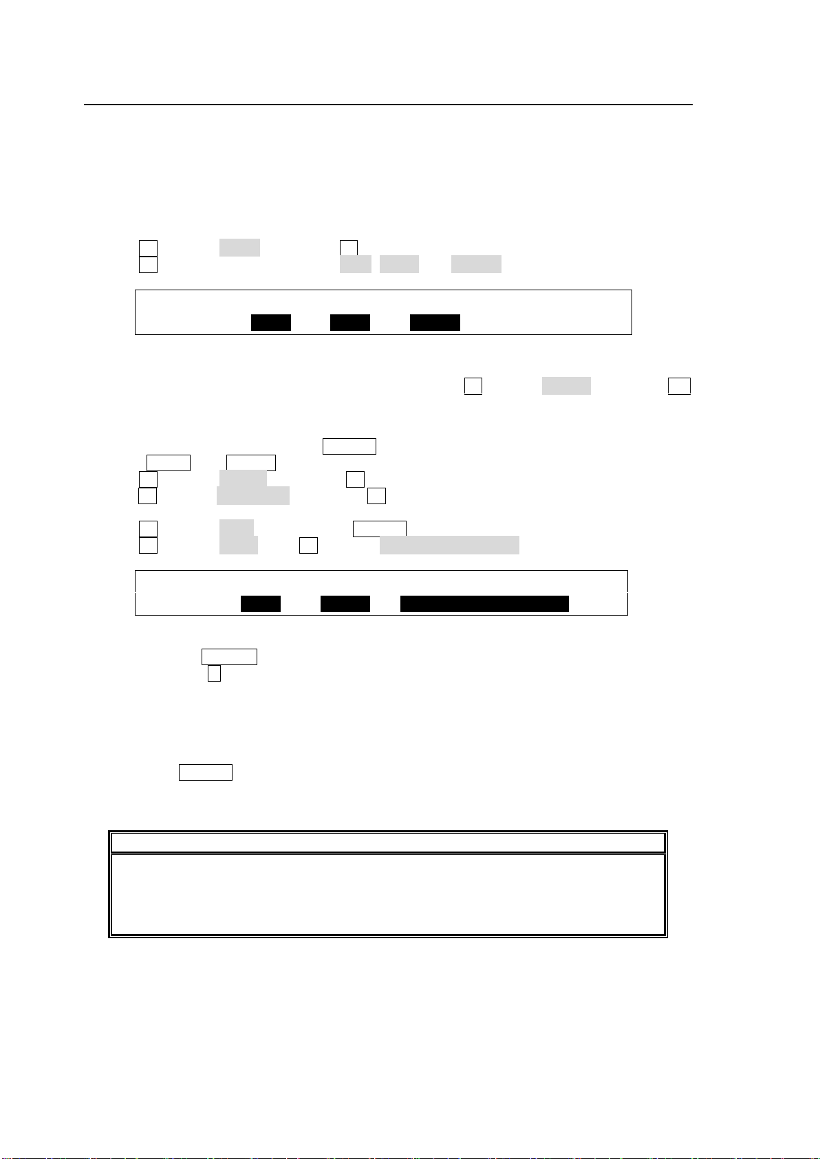
5-4. INPUT STILL (Freezing Input Video)
INPUT :SELECT :CONTROL:FREEZE : : 2/4
STILL : =IN01 : >GRAB : =FRAME: :
USER :SELECT : TYPE : FUNC(F3) : 1/2
BUTTON : =OU-1 : =STILL: =INPUT STILL STORE
IMPORTANT
INPUT STILLs use the frame synchronizer buffer memory. Therefore, the frame
synchronizer will be inoperable while an INPUT STILL image is being displayed or
enabled.
See section 5-7. "Frame Synchronizer."
Video inputs (IN01 to IN08) can display frozen images (INPUT STILLs) by capturing video. Still
images for INPUT STILLs can also be uploaded using the FILE menu.
See section 12-4-3. "Sending / Receiving Still Images.")
To Freeze Input Video
(1) Display [SETUP - INPUT - SIGNAL] menu PAGE 2.
(2) Select an input under SELECT.
(3) Turn F2 to select GRAB, then press F2. The input video will be displayed frozen.
(4) Turn F3 to select a freeze type from ODD, EVEN and FRAME.
Returning to the Input Video Display
To display the input video again from the frozen image, turn F2 to select CLEAR, then press F2.
To Freeze Input Video Using a User Button (Operation Example)
<Assigning INPUT STILL STORE to USER 1>
(1) Press MENU then SETUP in the SELECT/KEYPAD block to open the [SETUP] top menu.
(2) Turn F1 to select PANEL, then press F1 or the page down button to display the submenu.
(3) Turn F1 to select USER BTN, then press F1 or the page down button to display the [SETUP-
PANEL - USER BUTTON](1/2) menu.
(4) Turn F1 to select OU-1 (OU USER 1). USER 1 will blink.
(5) Turn F2 to select STILL. Turn F3 to select INPUT STILL STORE.
<Freezing IN01>
(1) Holding down USER 1, press the KEY/AUX bus button to which IN01 is assigned. (For
example, press 1 , if IN01 is assinged to Bus Button 1.)
(2) A still image for IN01 is automatically captured and saved to memory. Then the KEY/AUX
bus button will turn on and the IN01 output video will freeze (replaced with the captured still
image.)
<Restoring the IN01 Input Video>
Holding down USER 1, press the KEY/AUX bus button to which IN01 is assigned. The frozen
image for IN01 is cleared and the IN01 input video is restored and displayed on an output
screen.
40
Page 41
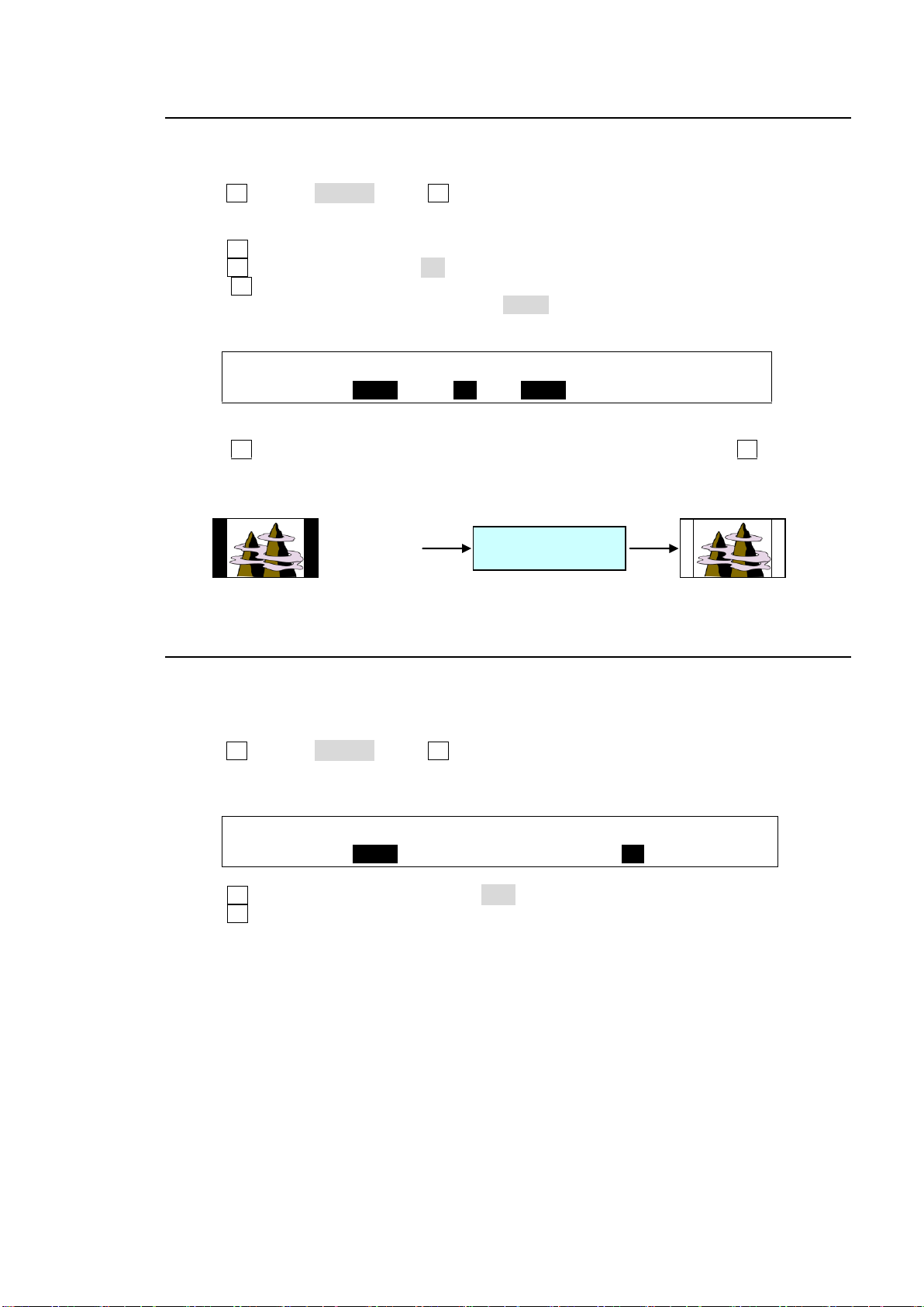
5-5. Changing the Side Panel Image
INPUT :SELECT : SIDE PANEL :XPT DLY: 3/4
SIDE PNL: =IN01 :En=ON S=SDMT : =0 :
INPUT :SELECT : SIDE PANEL :XPT DLY: 3/4
SIDE PNL: =IN01 :En=ON S=SDMT : =30 :
IN05 (SD)
(525/59.94i)
COLOR=WHITE
The side panel image of 4:3 video can be changed as shown in the procedure below.
(1) Display the [SETUP - INPUT] menu.
(2) Turn F1 to select SIGNAL. Press F1 or the page down button to display the [SETUP - INPUT
- SIGNAL] menu.
(3) To change the side bar color for 4:3 images, press the page down button to go to PAGE3.
(4 Turn F1 to select an input signal to which side panels are to be added.
(5) Turn F2 to set the side panel to ON.
(6) Turn F3 to select an input signal to be used for the side panel. Options are BLACK,
INPUT01-12, STILL1-2, and SDMT. Select SDMT (single color for side panel) for the signal
in this example.
(7) Press the page down button to go to PAGE 4 to set the SDMT color.
(8) Turn F4 to select a color from the following 8 standard colors. Then press F4 to apply the
setting. If you want to adjust the selected color or set the color by entering its HSL values.
See section 5-9. "Bus Matte" for details on how to set colors.
5-6. XPT DELAY
The XPT DELAY (crosspoint delay) feature allows you to add a time delay until a signal is
changed after pressing a bus button. To enable the feature, proceed as follows:
(1) Display the [SETUP - INPUT] menu.
(2) Turn F1 to select SIGNAL. Press F1 or the page down button to display the [SETUP - INPUT
- SIGNAL] menu.
(3) Press the page down button to go to PAGE 3.
(4) Turn F1 to select an input signal. Select IN01 in this example.
(5) Turn F4 to set a delay value in frames.
(6) Press IN01 (the bus button to which IN01 is assigned) on the PGM bus. The PGM image is
switched to the IN01 image 30 frames after the bus button is pressed.
41
Page 42
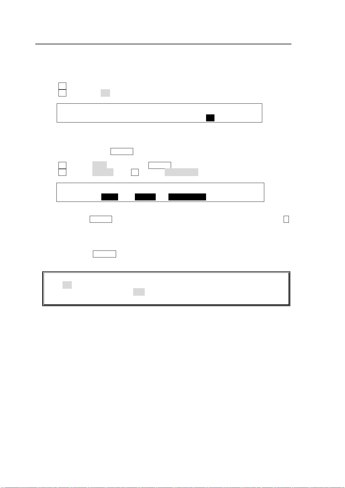
5-7. Frame Synchronizer
INPUT :SELECT :FORMAT :RESIZE : FS : 1/4
SIGNAL : =IN02 : =AUTO : =16:9 : =ON :
USER :SELECT : TYPE : FUNC(F3) : 1/2
BUTTON : =OU-3 : =OTHER: =FS ENABLE
Ancillary data in input video cannot be passed through if FS (input frame synchronizer) is
set to ON or RESIZE is enabled. To pass ancillary data, input the video synchronized with
the genlock signal and set FS to OFF. Note that ancillary data in SD inputs cannot be used
when the switcher operates in HD mode.
A video frame synchronizer is provided respectively for IN01 to IN08 and is used to synchronize
asynchronous signals. Users can select whether to apply frame synchronization to input signals
or not (for each signal) as shown in the procedure below.
(1) Display the [SETUP - INPUT - SIGNAL] menu.
(2) Turn F1 to select an input signal for use.
(3) Turn F4 to set FS to ON and activate the frame synchronizer.
To Enable/Disable FS Using a User Button (Operation Example)
<Assigning FS ENABLE to USER 3>
(1) Open the [SETUP - PANEL - USER BUTTON] (1/2) menu.
(2) Turn F1 to select OU-3 (OU USER 3). USER 3 will blink.
(3) Turn F2 to select OTHER. Turn F3 to select FS ENABLE.
<Enabling FS for IN01>
While holding down USER 3, press a KEY/AUX bus button to which IN01 is assigned. (Press 1 ,
for example, if IN01 is assigned to Bus Button 1.) The frame synchronizer function for IN01 will
be enabled.
<Disabling FS for IN01>
While holding down USER 3, press a KEY/AUX bus button to which IN01 is assigned. The
frame synchronizer function for IN01 will be disabled.
42
Page 43
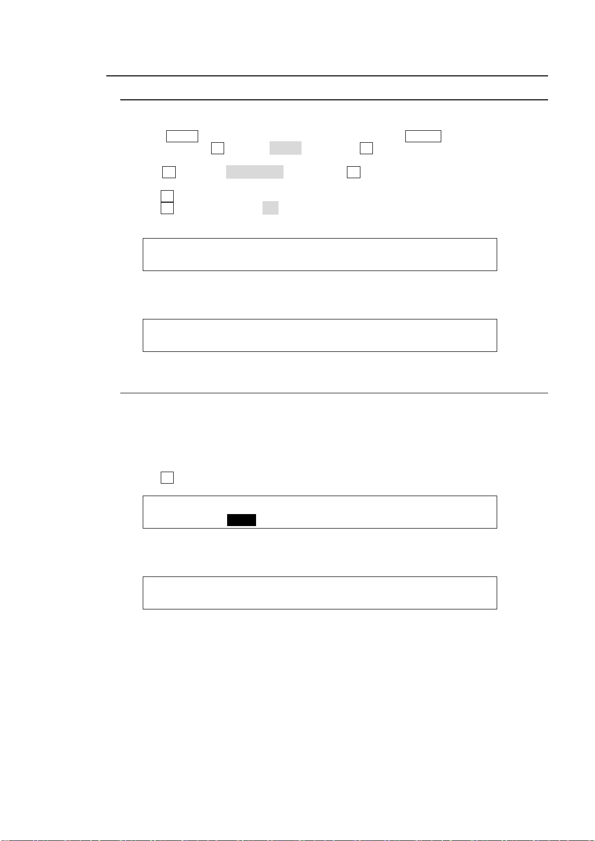
5-8. Adjusting Video Signal Levels
INPUT :SELECT :LumGain: Setup :ENABLE : 1/3
PROC AMP: =IN04 : =1.00 : =0 : =ON :
INPUT :SELECT :ChmGain: Hue :ENABLE : 2/3
PROC AMP: =IN04 : =10.00: =0.0 : =ON :
INPUT :SELECT :LumGain: Setup :ENABLE : 1/3
PROC AMP: =IN04 : =1.00 : =0 : =ON :
INPUT :WHT-Lv :BLK-Lv :Chroma : : 3/3
CLIP : =1019 : =4 : =1100 : :
5-8-1. Proc Amp
The switcher provides the following Proc Amp features.
(1) Press MENU in the SELECT/KEYPAD block, then press SETUP to display the SETUP
top menu. Turn F1 to select INPUT, then press F1 or the page down button to open the
[SETUP - INPUT] menu.
(2) Turn F1 to select PROC AMP, then press F1 or the page down button to open the
[SETUP - INPUT - PROC AMP] menu.
(3) Turn F1 to select the input to be adjusted.
(4) Turn F4 to set ENABLE to ON to enable the PROC AMP feature.
(5) You can adjust the luminance level under LumGain and the black level under Setup.
(6) Press the page down button to go to PAGE 2.
(7) You can adjust the chrominance level under ChmGain and the color under Hue.
5-8-2. Video Level Clip
To maintain the desired signal level after adjusting video levels with the Proc Amp, use the
Video Level Clip function to adjust the upper and lower limits of YPbPr color space. Note that
Video Level Clip can be applied only when the Proc Amp is enabled.
(1) Open the [SETUP - INPUT - PROC AMP] menu.
See section 5-8-1. "Proc Amp.")
(2) Turn F1 to select an input signal to be corrected.
(3) Press the page down button twice to go to PAGE 3.
(4) You can limit signal level settings under WHT-Lv, BLK-Lv and Chroma respectively.
43
Page 44
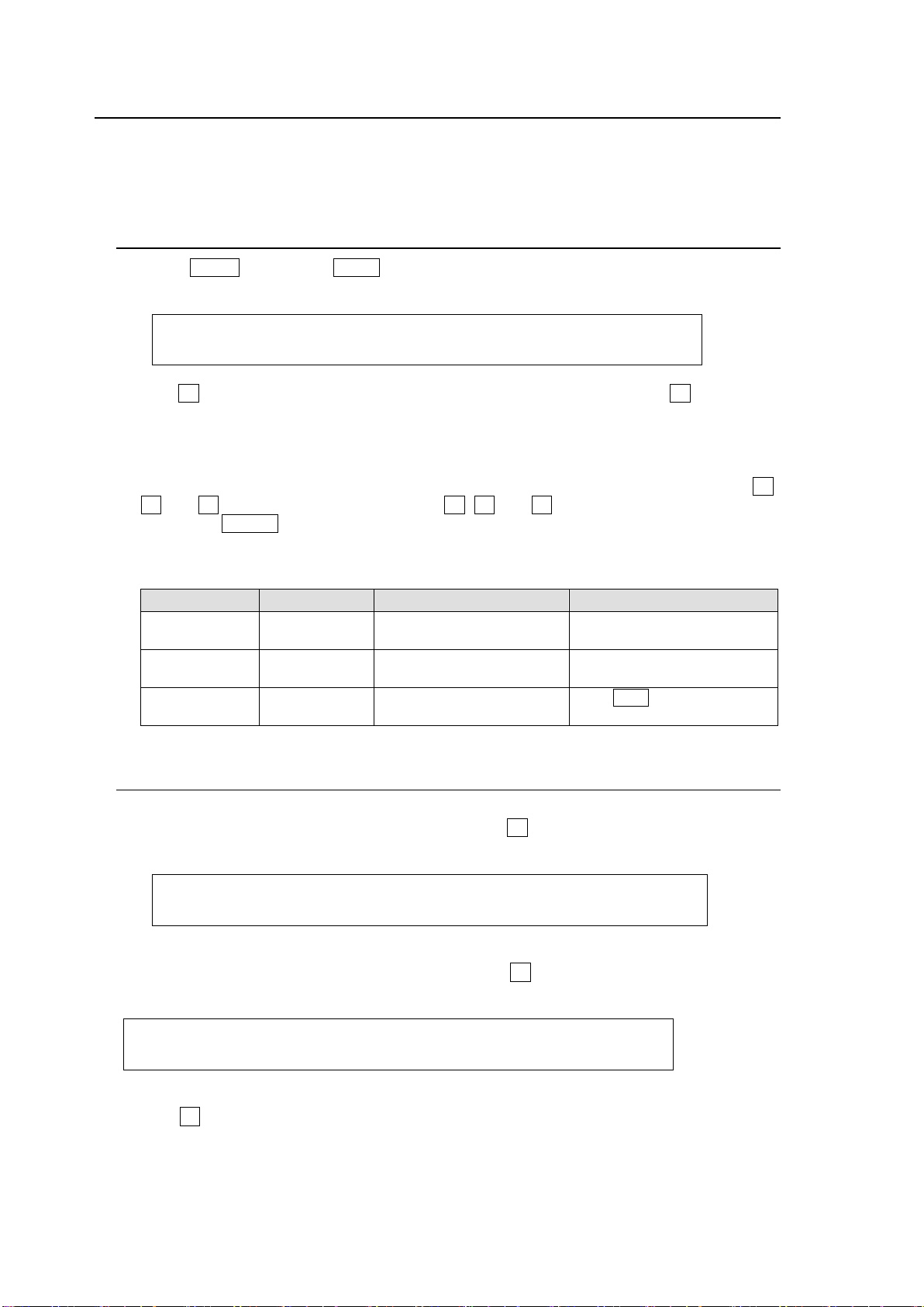
5-9. Bus Matte
MATT1 : BUS MATT1 COLOR :RECALL : 1/4
COLOR :S=50.0 L=80.2 H=125.5: >GREEN:
Parameter
Setting Range
Description
Joystick operation
S(Saturation)
0.0 to 100.0
Adjusts color saturation.
Moves Joystick horizontally
(X -axis)
L (Luminance)
0.0 to 100.0
Adjusts color luminance.
Moves Joystick vertically
(Y -axis)
H (Hue)
0.0 to 359.5
Adjusts color hue.
Turn SIZE cw or ccw.
(Z -axis)
MATT2 : BUS MATT2 COLOR1 :RECALL : 2/4
COLOR1 :S=50.0 L=80.2 H=125.5: >GREEN:
MATT2 : BUS MATT2 COLOR2 :RECALL : 3/4
COLOR2 :S=50.0 L=80.2 H=125.5: >GREEN:
Matte signals can be assigned to any bus buttons for PGM, PST and KEY/AUX. (Default
assignment: MAT1 to Button 12). Bus matte colors can be specified in the [MATT COLOR]
menu.
5-9-1. Setting the Matte Color
(1) Press MENU then press MATT in the SELECT/KEYPAD block to display the MATT
menu.
(2) Turn F4 to select a color from the following 8 standard colors. Then press F4 to apply the
setting.
WHITE, YELLOW, CYAN, GREEN, MAGENTA, RED, BLUE and BLACK
If you want to adjust the selected color or set the color by entering its HSL values, turn F1,
F2 and F3 to enter these values or press F1, F2 and F3, enter a value from the keypad
then press ENTER (from the keypad). Users can also set these three parameters via the
JOYSTICK block.
See section 4-2-4. "Changing Settings or Values Using the Joystick."
5-9-2. Setting the Gradient Matte
(1) Display [BUS MATT 2 COLOR] menu PAGE 2.
(2) To select a start color for the gradient matte, turn F4 to select a color or enter the HSL
values to specify the color.
(3) Press the page down button to go to [MATT COLOR] menu PAGE 3.
(4) To select an end color for the gradient matte, turn F4 to select a color or enter the HSL
values to specify the color.
(5) Press the page down button to go to [MATT COLOR] menu PAGE 4.
(6) Turn F1 to select a pattern for the gradation matte. Set the position at POS and border
softness at SOFT.
44
Page 45

MATT2 :PATTERN : POS : SOFT : 4/4
GMAT : =H : =0 : =0 :
PATTERN setting
Description
COLOR1
Displays the matte color set at BUS MATT2 COLOR1.
H
Displays a horizontal gradient from COLOR1 to COLOR2.
V
Displays a vertical gradient from COLOR1 to COLOR2.
H/V
Displays a diagonal gradient from COLOR1 to COLOR2.
45
Page 46
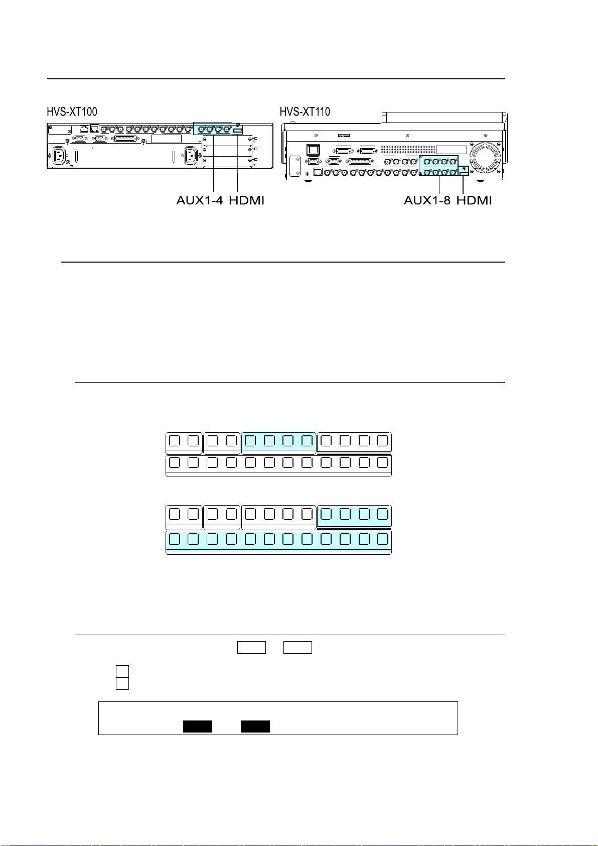
6. Video Outputs
OUTPUT :SELECT : XPT : TRANS RATE : 1/3
OUT XPT : =AUX1 : =IN01 :En=OFF =OFF :
1 1 1
1
2 2 2 3 4
2 3 4 5 6 7 8 9 10 11 12
KEYER DSK AUX
KEY/AUX
PGM PREV C LEAN MV
1 1 1
1
2 2 2 3 4
2 3 4 5 6 7 8 9 10 11 12
KEYER DSK AUX
KEY/AUX
PGM PREV CL EAN MV
REF OUT 1 12 3 4 5 6 7 8 2 3 4REF IN
HDMI OUT
AUX
5 6 7 8
AUX
LAN
SDI INPUT
9 10 11 12
SDI INPUT
GPI IN/TALLY OUT
DC12V IN
1 2
MODE SW
POWER
OFF ON
GENLOCK
RS-422
1 2
REF OUT 112 3 4 5 6 7 8
2 3 4
A
B
C
REF IN
1 2
2
AC100-240V 50/60Hz INAC100-240V 50/60Hz IN
1
TO OU
LAN GENLOCK SDI INPUT
RS-422 GPI IN/TALLY OUT
HDMI OUTAUX
6-1. Aux Outputs
The switcher does not have any dedicated outputs for combined video such as Program or
Preview images. Instead, eight user-assignable AUX ports are provided. AUX output signals
can be selected from all bus sources (primary inputs, stills, mattes, etc.), program, preview,
clean and key out signals. There are two signal selection procedures for auxiliary outputs: via
bus buttons or from menu selection. If you want to select a signal easily and quickly, select the
signal in the KEY/AUX bus. If you want to select a signal not assigned to bus buttons, select it in
the menu.
6-1-1. Selecting Video via Bus Buttons
AUX1-4 outputs can select signals using the bus buttons.
(1) Press an AUX button, from AUX1 to AUX4 indicated below.
(2) Press a button in the KEY/AUX bus section to select a signal for the selected AUX output.
AUX5 to AUX8 bus buttons can be assigned to USER buttons.
See section 14. "USER Buttons."
6-1-2. Selecting Video from Menu Selection
(1) Double-press an AUX button (AUX1 to AUX4) on the left side of the control panel to
display the [SETUP - OUTPUT - OUT XPT] menu.
(2) Turn F1 to select an AUX bus.
(3) Turn F2 to select a video signal.
46
Page 47
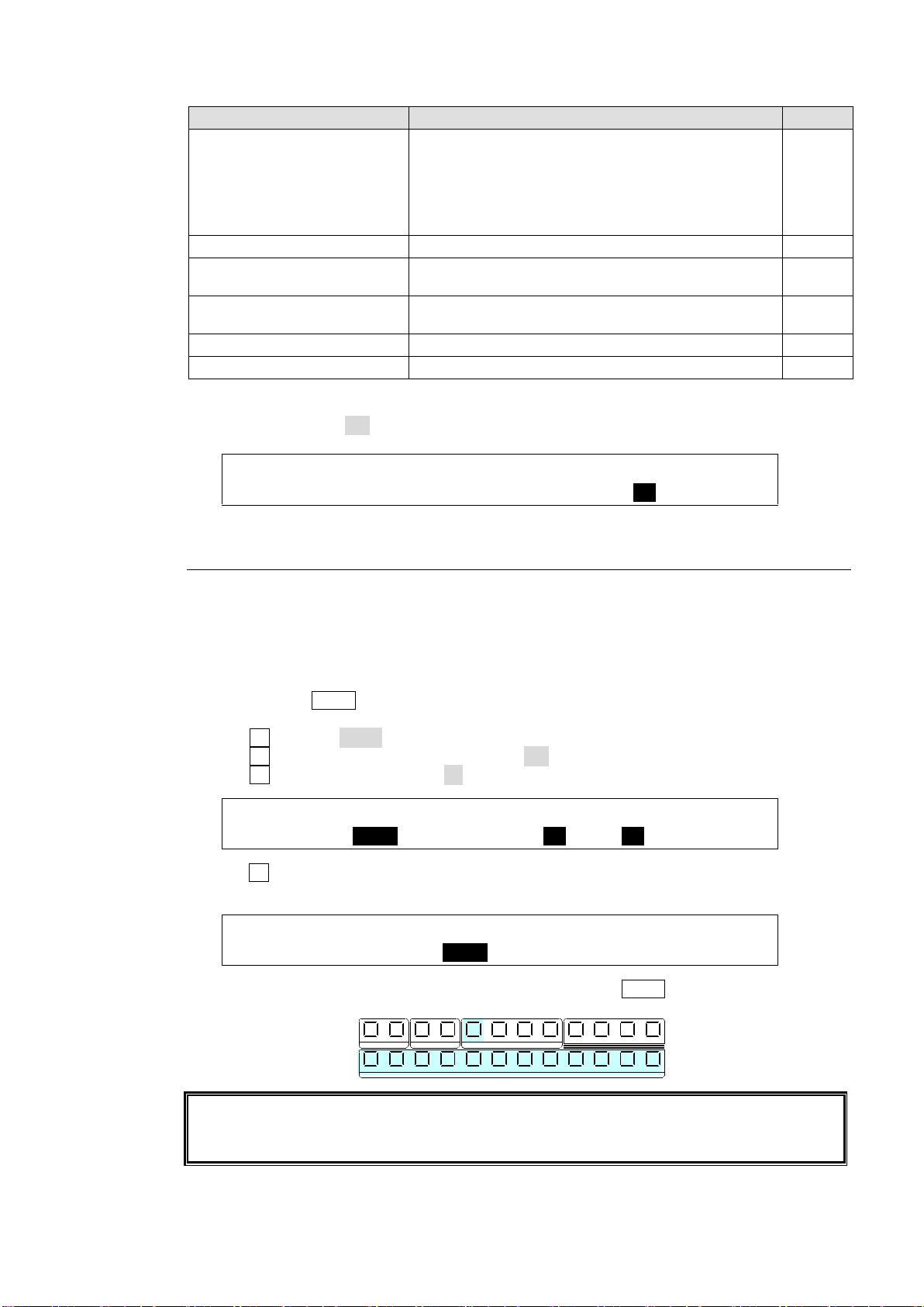
Available signal selections are as described below:
Button
Signal
Refer to
BLACK,
IN01-08 (XT100)
IN01-12 (XT110),
STILL1-2, STILLK1-2,
CKFIL, CKKEY,
MATT1-2, CLBAR, EFF1-2
Signals assignable to M/E and KEY/AUX bus
buttons
5-2
PGM
Program video
PREV
Preview video
(next video with or without KEY1-2 and DSK1-2)
6-2
CLEAN
Clean video
(program video with or without KEY1-2 and DSK1-2)
6-3
KEY
Key cut signal combined with Key, DSK and DVE
6-4
MV
Multiviewer video
13-1
OUTPUT :M/E KEY: : AUX INHIBIT : 2/3
OUT XPT : =MEKEY: :S=AUX1 En=ON :
OUTPUT :SELECT : XPT : TRANS RATE : 1/3
OUT XPT : =AUX1 : =IN01 :En=ON =30 :
OUTPUT :SELECT : XPT : TRANS RATE : 1/3
OUT XPT : =AUX1 : =IN05 :En=ON =30 :
AUX bus transition effects are enabled when video input, matte, still or program signals are
assigned to the AUX outputs. When multi-view images are assigned to AUX buses,
however, video streams are switched using CUT.
1 1 1
1
2 2 2 3 4
2 3 4 5 6 7 8 9 10 11 12
KEYER DSK AUX
KEY/AUX
PGM PREV CLEAN MV
(4) To prevent operational errors, AUX signal selection via bus buttons can be disabled by
setting INHIBIT to ON in the [SETUP - OUTPUT - OUT XPT] (2/3) menu.
6-1-3. AUX Video Switching with Effects
The background video displayed on an AUX bus can be easily switched using effects. The
auxiliary video can be changed using crossfade transitions. This chapter explains how to
switch AUX video using an operational example.
Ex.) : Changes the AUX1 video in 30 frames using a crossfade.
(1) Double-press AUX1 on the left side of the control panel to display the [SETUP - OUTPUT-
OUT XPT] (1/3) menu.
(2) Turn F1 to select AUX1.
(3) Turn F3 to set TRNS RATE En (Enable) to ON.
(4) Turn F4 to set TRANS RATE to 30 frames.
(5) Turn F2 to select the next video. The current video will fade out and a new image will fade
into the screen in 30 frames.
(6) Let's change the AUX1 video on the control panel. Press AUX1 then select a video in the
KEY/AUX bus.
47
Page 48
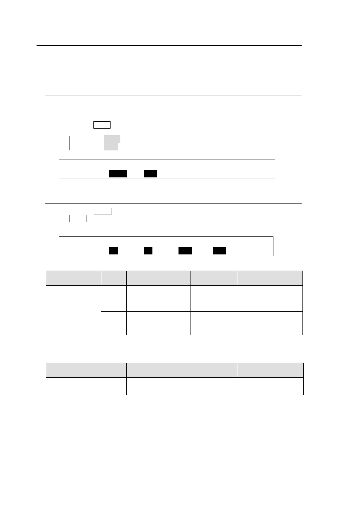
6-2. Preview Set Up
OUTPUT :SELECT : XPT : TRANS RATE : 1/3
OUT XPT : =AUX1 : =PVW :En=OFF =0 :
OUTPUT : KEY1 : KEY2 : DSK1 : DSK2 : 2/2
M/E PRV : =ON : =ON : =OFF : =OFF :
Parameter
Setting
NEXT TRANSITION
KEY
On-Air/Off-Air
KEY1-2 on
PREVIEW images
PREVIEW OUT KEY1
ON
KEY1 button ON
On-Air
Not displayed
ON
KEY1 button OFF
On-Air
Displayed
PREVIEW OUT KEY2
ON
KEY2 button ON
Off-Air
Displayed
ON
KEY2 button OFF
Off-Air
Not displayed
PREVIEW OUT KEY1-2
OFF
---
---
Not displayed
Whether KEY images are displayed on the preview depends on both the PREVIEW OUT settings and KEY
button status in the NEXT Transition block.
Parameter
Setting
DSK1-2 on
PREVIEW images
PREVIEW OUT - DSK1
PREVIEW OUT - DSK2
ON
Displayed
OFF
Not displayed
The switcher does not have a dedicated PREVIEW output. A preview bus output can be
assigned to, however, an AUX output. Users can also add key images to PREVIEW. This can be
done as explained below:
6-2-1. Preview Bus Monitoring
Follow the procedure below to assign a preview video to an AUX output. AUX1 is used in the
example below.
(1) Double-press AUX1 on the left side of the control panel to display the [SETUP - OUTPUT
- OUT XPT] (1/3) menu.
(2) Turn F1 to select AUX1.
(3) Turn F2 to select PVW.
6-2-2. Setting Up Preview Images
(1) Double-press PREV to display the [SETUP - OUTPUT - CLN/PREV] (2/2) menu.
(2) Turn F1 to F4 to set whether the key images are to be displayed on the preview image,
then press the push-button to confirm the setting for each.
KEY1-2
DSK 1-2
48
Page 49
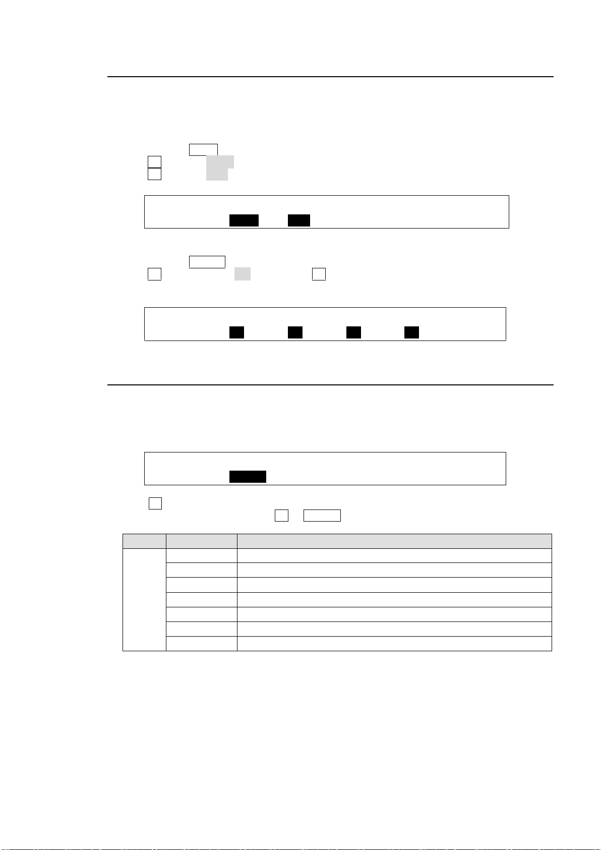
6-3. Clean Set Up
OUTPUT :SELECT : XPT : TRANS RATE : 1/3
OUT XPT : =AUX3 : =CLN :En=OFF =0 :
OUTPUT : KEY1 : KEY2 : DSK1 : DSK2 : 1/2
M/E CLN : =ON : =ON : =ON : =ON :
OUTPUT :M/E KEY: : AUX INHIBIT : 2/3
OUT XPT : =MEKEY: :S=AUX1 En=OFF :
Item
Setting
Description
M/E
KEY
PGM
Key signal of PGM when using DVE
PST
Key signal of PST when using DVE
ME A
Key signal of M/E-A when using DVE
ME B
Key signal of M/E-B when using DVE
KEY1, KEY2
Key signal of each KEY1 or KEY2
DSK1, DSK2
Key signal of each DSK1 or DSK2
MEKEY
Key signal of program including KEY1-2 and DSK1-2
The switcher can output CLEAN video (background video of the program signal) via an auxiliary
output. Users can also add KEY or DSK images to CLEAN. Follow the procedure below to
assign the clean video to an AUX output. AUX3 is used in this example.
Outputting the Clean Video from AUX 3
(1) Double-press AUX1 to display the [SETUP - OUTPUT- OUT XPT](1/3) menu.
(2) Turn F1 to select AUX3.
(3) Turn F2 to select CLN.
Displaying KEY1-2 and DSK1-2 Images on the Clean Video
(1) Double-press CLEAN to display the [SETUP - OUTPUT - CLN/PREV] (1/2) menu.
(2) Turn F1 to set KEY1 to ON. Then press F1 to confirm the setting.
(3) Set KEY2 and DSK1-2 in the same way.
6-4. KEY OUT Set Up
The KEY OUT signal, switcher processed key cut signal (alpha channel), can be assigned to
AUX outputs. Various kinds of key cut signals can be used for KEY OUT sources.
(1) Open [SETUP - OUTPUT - OUT XPT] menu PAGE 2.
(3) Turn F1 to select a KEY OUT signal. Various types of KEY OUT signals are available as
shown in the table below. Press F1 or ENTER to confirm the setting.
49
Page 50
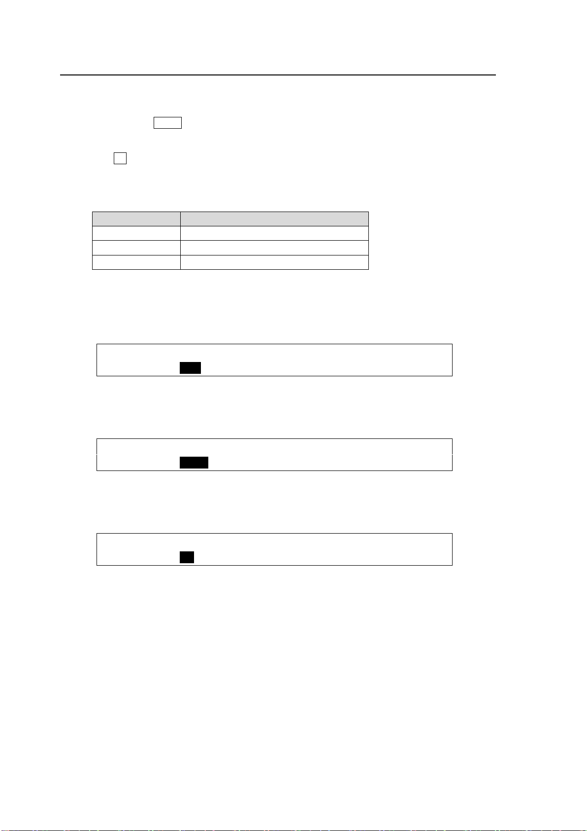
6-5. HDMI Output
System Format
Output signal format
1080i
HDTV (1920 x 1080)
720p
HDTV (1280 x 720)
SD
SDTV (720 x 480)
OUTPUT : XPT : : 3/3
HDMI OUT: =PGM : :
OUTPUT : XPT : : 3/3
HDMI OUT: =AUX1 : :
OUTPUT : XPT : : 3/3
HDMI OUT: =MV : :
Video output through the HDMI port can be selected from an M/E program, preview, clean or
key out video, to AUX1-8 and MV.
(1) Double-press AUX1 on the left side of the control panel to display the [SETUP - OUTPUT
- OUT XPT] (1/3) menu.
(2) Press the page down button to go to PAGE 3.
(3) Turn F1 to select a video to be output from the HDMI port.
Available options are:
PGM, PREV, CLEAN, MEKY and AUX1-8 and MV
Signals are output at the same frequency as that of the system format.
Ex. 1
Switcher System Format: 1080/59.94i
To Output the PGM video (at 1920 x 1080 resolution):
Ex. 2
Switcher System Format: 720/50p
To Output the AUX1 video (at 1280 x 720 resolution):
Ex. 3
Switcher System Format: SD PAL (625/50)
To Output the MV SDTV video:
50
Page 51
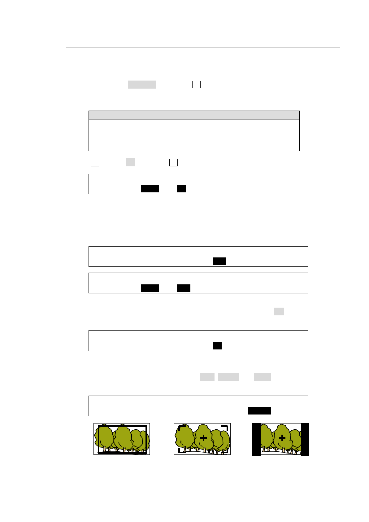
6-6. Safety Area Markers
XT100
XT110
AUX1 to AUX4
B-Ch1, B-Ch2 (Support planned)
C-Ch1, C-Ch2(Support planned)
HDMI
AUX1 to AUX8
HDMI (HDMI OUTPUT)
OUTPUT :SELECT :ENABLE :MARKER :SIDECUT: 1/2
MARKER : =AUX1 : =ON : =BOX : =OFF :
OUTPUT :SELECT :ENABLE :MARKER :SIDECUT: 1/2
MARKER : =AUX1 : =ON : =BOX : =OFF :
OUTPUT :ASPECT : SIZE :CENTER : : 2/2
MARKER : =16:9 : =85% : =ON : :
OUTPUT :ASPECT : SIZE :CENTER : : 2/2
MARKER : =16:9 : =85% : =ON : :
OUTPUT :SELECT :ENABLE :MARKER :SIDECUT: 1/2
MARKER : =AUX1 : =ON : =OFF : =BLACK:
MARKER: BOX
ASPECT: 16:9
SIZE: 85%
MARKER: HOOK
ASPECT: 16:9
SIZE: 85%
CENTER: ON
MARKER: OFF
SIDECUT: BLACK
CENTER: ON
Various markers indicating the safety area, screen center and aspect ratio can be displayed on
the desired output.
(1) Open the [SETUP - OUTPUT] menu.
(2) Turn F1 to select MARKER, then press F1 or the page down button to open the [SETUP -
OUTPUT - MARKER] menu.
(3) Turn F1 to select a video output.
(4) Turn F2 to set to ON then press F2 to enable the Marker function.
Safety Area Marker
To display a safety area marker in the selected output, first select the type of marker under the
MARKER item in the [SETUP - OUTPUT - MARKER] menu from BOX and HOOK. (See the
figures at the bottom of the page.) Then go to PAGE 2, select an aspect ratio, and set the marker
size.
Center Marker
To display the center marker in the selected output, set CENTER to ON in PAGE 2 of the
[SETUP - OUTPUT - MARKER] menu. (See the figures at the bottom of the page.)
Side Cut Display
To display a Side Cut image converting the aspect ratio from 16:9 to 4:3, select the display type
under the SIDECUT item. Available types are LINE, BLACK and HALF. (See the figures at the
bottom of the page.)
51
Page 52
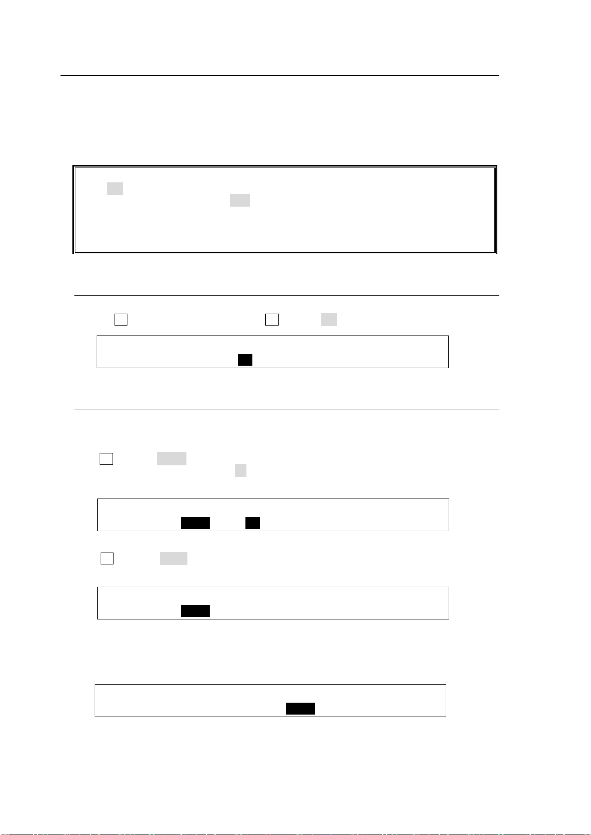
6-7. Ancillary Data
Ancillary data in input video cannot be passed through if FS (input frame synchronizer) is
set to ON or RESIZE is enabled. To pass ancillary data, input the video synchronized with
the genlock signal and set FS to OFF.
See section 5-3. "Resize Function" and section 5-7. "Frame Synchronizer."
Note that ancillary data in SD inputs cannot be used when the switcher operates in HD
mode.
OUTPUT :SELECT :ENABLE : : 2/2
ANCI THR: =AUX1 : =ON : :
OUTPUT : M/E PGM SWAP :PREV SW: : 1/2
ANCI SWP: =EACH Lv=50 : =OFF : :
OUTPUT : M/E PGM SWAP :PREV SW: : 1/2
ANCI SWP: =AUX1 Lv=50 : =OFF : :
OUTPUT : M/E PGM SWAP :PREV SW: : 1/2
ANCI SWP: =AUX1 Lv=50 : =EACH : :
Ancillary data does not pass through all outputs as the factory default setting.
The switcher can be set to pass or blank the ancillary data in the AUX outputs using the menu.
The switcher also allows users to pass or substitute ancillary data in the Program (Clean) and
Preview video. Ancillary data in the current video stream is once cleared, then the same or
different data inserted.
Ancillary data operation is set in the [SETUP - OUTPUT - ANCI] menu.
6-7-1. Passing Incoming Ancillary Data on-through to AUX Outputs
(1) Open the [SETUP - OUTPUT - ANCI] menu PAGE 2.
(2) Turn F1 to select an output, then turn F2 to set to ON (pass).
6-7-2. Ancillary Data in PGM and PREV Bus Signals
Program (Clean) bus
To Pass Through Ancillary Data
Turn F1 to select EACH. The Lv (level) item selects the point at which the new data is to be
inserted, from 0-100. Setting Lv to 50 passes ancillary data through from the halfway point of
the background transition.
To Replace Ancillary Data with Data in an AUX bus signal
Turn F1 to select AUX1. Ancillary data in the program bus signal is replaced with ancillary
data in AUX1 video. (Note that the Lv setting is ignored.)
Preview bus
Ancillary data in the Preview bus signal can be processed in the same way as that for the
program bus under PREV SW.
52
Page 53
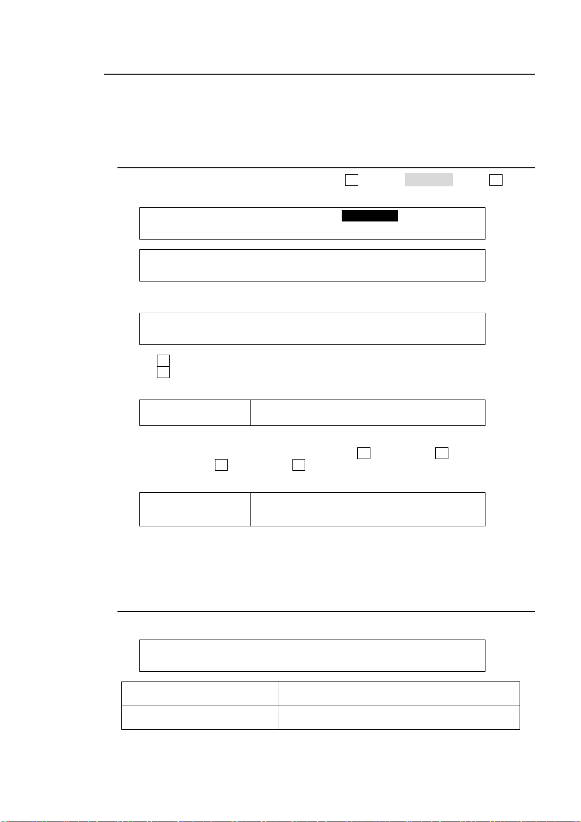
6-8. AUX LINK
SETUP :>M/E_KEY >VIRTUAL >AUX LINK
FUNCTION:
FUNCTION:ENABLE : : 1/3
AUX LINK: =OFF : :
FUNCTION:SELECT:MASTER: SLAVE SEL/AUX : 2/3
AUX GRP : =1 : =AUX1:1=AUX2 2=AUX3 3=AUX4
Master Output
AUX1-8, PGM, PST
ABUS, BBUS, KEY1, KEY2, DSK1, DSK2
Slave Output
(Normal link)
Same options as Master Output.
Note that video set as Master cannot be selected for
the Slave.
FUNCTION:SELECT:MASTER: SLAVE SEL/AUX : 3/3
LINK GRP: =1 : =IN01:1=IN02 2=IN03 3=IN04
Available Signals
BLK, IN01 to 12, STL1, STL2, STK1, STK2, CKFL,
CKKY, EFF1, EFF2, CB, MAT1, MAT2
(If AUX1-8 is selected for the
MASTER or SLAVE bus)
PGM, PVW, CLN, MEKY, MV
In the AUX-LINK function, the auxiliary outputs are grouped, and the master and slave outputs
are set to allow all slave output signals to be switched simultaneously by simply selecting the
master output signal. A group consists of one master output and up to three slave outputs.
Seven auxiliary output groups can be set. Examples of AUX LINK settings and operation are
shown below.
6-8-1. Creating AUX Output Link Groups
(1) Open the [SETUP - FUNCTION] menu. Turn F1 to select AUX LINK. Press F1 or the
page down button to display the AUX LINK menu.
(2) Press the page down button again to go to the [AUX LINK - AUX GRP] menu page.
(3) Turn F1 to select a group to be set from 1-7
(4) Turn F2 to set the auxiliary output serving as the MASTER. Available outputs are shown
below.
(5) Select the auxiliary outputs (up to three) serving as the SLAVE linking to the MASTER
output. Available outputs are shown below. Press F3 and then turn F3 to select an output
for Slave 1. Press F3 and then turn F3 to select an output for Slave 2. Select an output for
Slave 3 in the same way.
The A or B bus cannot be set for Slave when the Program or Preset bus is selected for Master.
In the same way, the Program or Preset bus cannot be set for Slave output when the A or B
bus is selected for Master.
6-8-2. Creating Signal Link Groups
(1) Press the page down button to go to the [AUX LINK - LINK GRP] menu.
53
Page 54
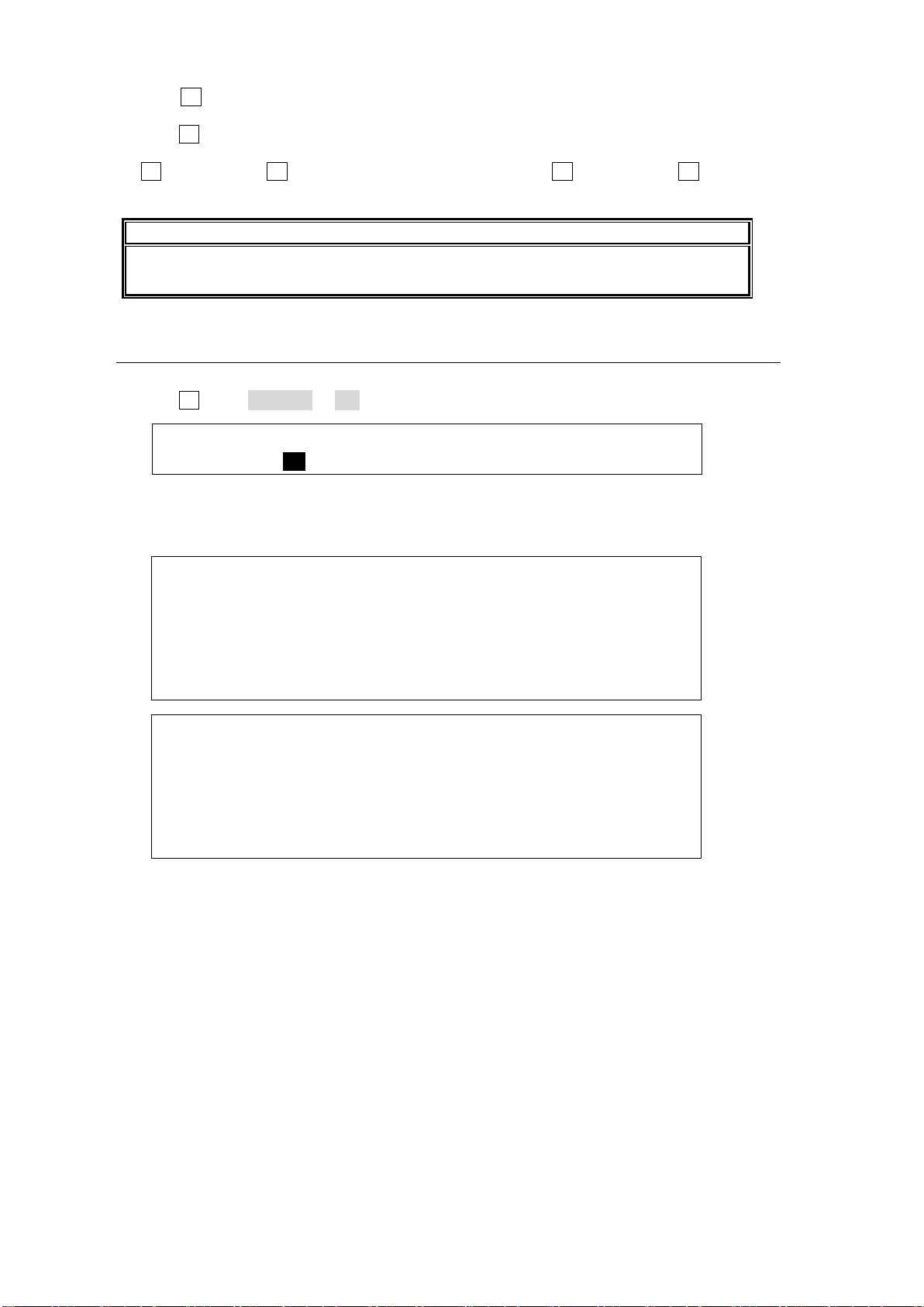
(2) Turn F1 to select an AUX LINK group to be set in the LINK GROUP menu (up to 20
NOTE
The same MASTER output signal cannot be selected twice. SLAVE output signals can
be selected multiple times.
FUNCTION:ENABLE : : 1/3
AUX LINK: =ON : :
:SELECT:MASTER: SLAVE SEL/AUX : 2/3
AUX GRP : =1 : =AUX1 :1=AUX2 2=AUX3 3=AUX4
: =2 : =AUX7 :1=AUX8 2=OFF 3=OFF
: =3 : =PGM :1=KEY1 2=KEY2 3=OFF
: =4 : =ME-A :1=ME-B 2=OFF 3=OFF
: =5 : =OFF :1=--- 2=--- 3=---
: ... : ... : ...
:SELECT:MASTER: SLAVE SEL/AUX : 3/3
LINK GRP: =1 : =IN01 :1=IN02 2=IN03 3=IN04
: =2 : =PGM :1=PREV 2=OFF 3=OFF
: =3 : =IN05 :1=STL1 2=STL2 3=OFF
: =4 : =IN06 :1=IN07 2=OFF 3=OFF
: =5 : =OFF :1=--- 2=--- 3=---
: ... : ... : ...
groups).
(3) Turn F2 to select a signal to be set for MASTER
(4) To set the SLAVE output signals (up to three) that link to the MASTER output signal, press
F3 and then turn F3 to select a signal for Slave 1. Press F3 and then turn F3 to select a
signal for Slave 2. Select a signal for Slave 3 in the same way.
6-8-3. Enabling AUX LINK
(1) Display the [SETUP - FUNCTION - AUX LINK] menu.
(2) Turn F1 to set ENABLE to ON. This activates all AUX LINK groups.
Operation examples:
Assume that the AUX output link groups and their signal link groups were set as shown
below.
Press AUX1 in the BUS SELECT-AUX block and select IN01 on the AUX/KEY bus:
>> IN02 is assigned to AUX2, IN03 to AUX3 and IN04 to AUX4.
Press AUX7 in the BUS SELECT-AUX block and select PGM:
>> PREV is assigned to AUX8.
Select IN05 in PGM bus:
>> STL1 is assigned to KEY1-INSERT and STL2 to KEY2-INSERT.
Select IN06 in M/E- A bus:
>> IN07 is assigned to M/E-B bus
54
Page 55
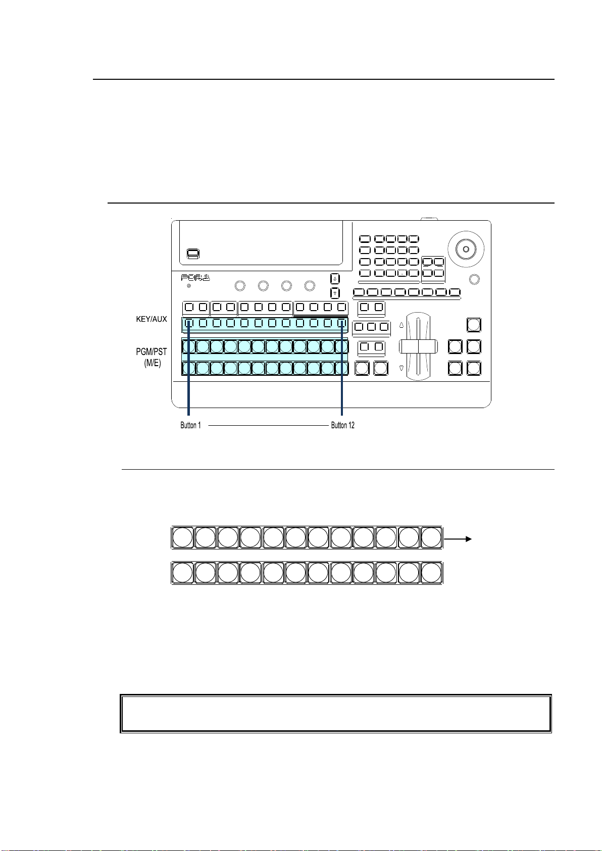
7. Bus Operation
Users can change the M/E bus mode from PGM/PST to A/B.
See section 7-2. "Button Switching Mode in M/E Bus."
USB MEMORY
DIGITAL VIDEO SWITCHER HVS-
XT
SIZE
(PUSH to DEF)
1 2 3 4 5 6 7 8
USER BUTTON
REV NOR/REV
DIRECTION
BLACK
TRANS
BKGD KEY1 KEY2
NEXT TRANSITIO N
MIX WIPE
KEY1 KEY2
TRANSITION T YPE
AUTO CUT DSK1 DSK2
ALARM
F1 F2 F3 F4
PAGE
1 1 1
1
2 2 2 3 4
2 3 4 5 6 7 8 9 10 11 12
KEYER DS K AUX
KEY/AUX
PGM PREV CLEAN MV
PGM
PST
1 2 3 4 5 6 7 8 9 10 11 12
MENU ATTACH
DIRECT
PATT
DETACH
SETUP
KEY1
POSITION
POS ROT
2D DVE
WIPE
POS
MENU
JOYSTICK
8 9
4 5 6
STILL MATT FILE
KEY2 DSK1 DSK2
EVENT
MACRO
1 2 3
0
CLEAR
RECALL STORE
ENTER
CK EFFECT
TRANS RATE WIPE
SELECT/KEYPAD
±
7
PGM
PST
1 2 3 4 5 6 7 8 9 10 11 12
PGM row
PST row
PGM output
Video signals that are input to the switcher are assigned to the bus buttons on the control panel for
usage. The assigned signals are shared by the M/E(PGM/PST) and KEY/AUX bus sections.
As factory default settings, video inputs, Stills and Mattes are assigned to the bus buttons. The
video source assignments are freely changeable. To prevent accidental button operation, the
Button Inhibit function is also available.
See section 5-2. "How to Assign Sources to Bus Buttons."
7-1. Selecting Video Sources
7-1-1. Selecting Video Sources on the PGM/PST
Press the desired bus button on the PGM bus. The button light will turn red and the video
signal assigned to the selected bus button is displayed on the program output screen.
Press the desired bus button on the PST bus. The button light will turn orange and the video
signal assigned to the selected bus button is displayed on the preview output screen. Then
move the fader lever from end to end to check how the button indication changes as the
signals are switched. Once the transition is complete, the selected signals on PGM and PST
are switched (flip-flop).
The switcher's primary operation is to select the next video on the PST bus and send it to air
via transition. And to repeat the process over and over.
55
Page 56
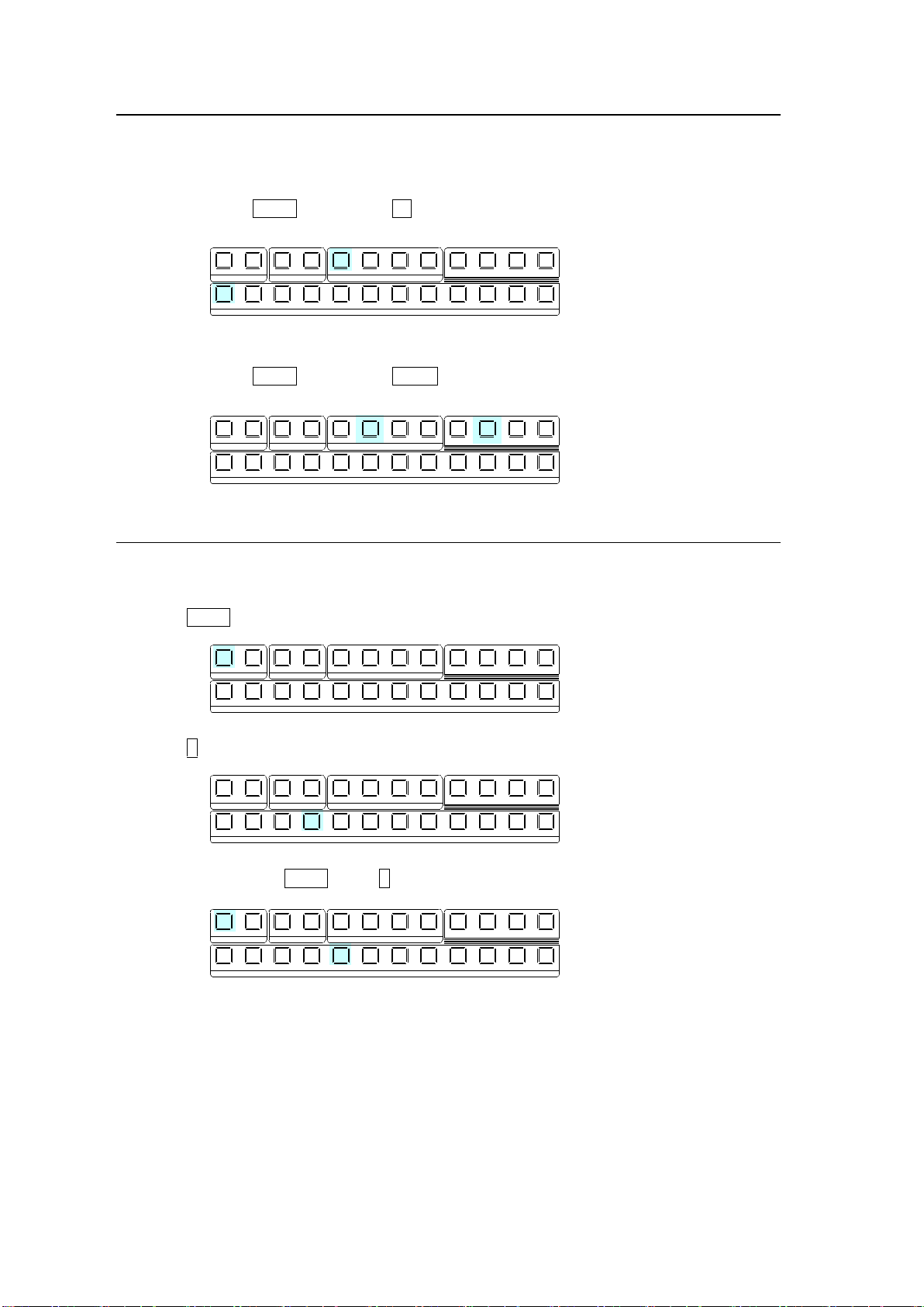
7-1-2. Selecting Video Sources for AUX1 to AUX4
1 1 1
1
2 2 2 3 4
2 3 4 5 6 7 8 9 10 11 12
KEYER DSK AUX
KEY/AUX
PGM PREV C LEAN MV
1 1 1
1
2 2 2 3 4
2 3 4 5 6 7 8 9 10 11 12
KEYER DSK AUX
KEY/AUX
PGM PREV C LEAN MV
1 1 1
1
2 2 2 3 4
2 3 4 5 6 7 8 9 10 11 12
KEYER DSK AUX
KEY/AUX
PGM PREV C LEAN MV
1 1 1
1
2 2 2 3 4
2 3 4 5 6 7 8 9 10 11 12
KEYER DSK AUX
KEY/AUX
PGM PREV C LEAN MV
1 1 1
1
2 2 2 3 4
2 3 4 5 6 7 8 9 10 11 12
KEYER DSK AUX
KEY/AUX
PGM PREV C LEAN MV
(1) Press the desired AUX button.
(2) Press a desired button on the KEY/AUX bus.
Ex.1) To Select IN1 for AUX1
Press AUX1. Then press 1 (IN01) on the KEY/AUX.
Ex. 2) To Select PREV for AUX2
Press AUX2. Then press PREV on the KEY/AUX.
7-1-3. Selecting Video Sources for KEY and DSK
To select the bus button 4 video for KEY1 Insert (fill) and the bus button 5 video for KEY1
Source (key), proceed as follows.
(1) Press KEY1.
(2) Press 4 in the KEY/AUX bus to select the KEY1 Insert signal.
(3) While holding down KEY1, press 5 in the KEY/AUX bus to select the KEY1 Source signal.
Once insert and source signals are selected for a key or DSK, they are stored as a key pair
and when a key or DSK then selects an insert signal, the paired source signal is automatically
set.
See section 9-3-1. "Key Link."
56
Page 57
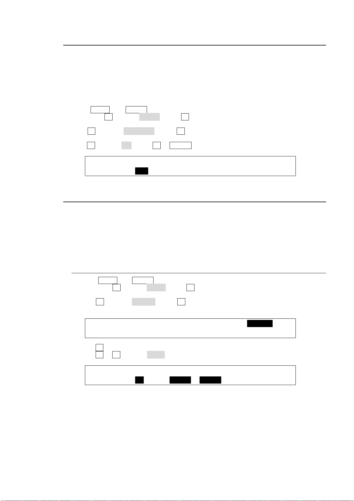
7-2. Button Switching Mode in the M/E Bus
PANEL :BUSTYPE: : FADER OFFSET : 1/1
M/E CTRL: =A/B : :U=1.00 L=1.00 :
SETUP :>SIGNAL >PROC AMP>RENAME >ASSIGN
INPUT :>COLORBAR
INPUT :BUTTON : SIGNAL NAME :INHIBIT: 1/3
OU ASGN : =12 : =SHIFT =SHIFT : =OFF :
Users can change the button switching mode for the M/E bus from P/P (PGM/PST) to A/B. In
P/P mode (default), the source selections in the PGM and PST buses are switched when
transitions occur and users can always select the next background signal from the PST bus (the
bottom row). In A/B mode, the source selections in the PGM and PST buses do not switch when
transitions occur and the next signal selection takes place in the different bus after each
transition.
To Change the Switching Mode to A/B:
(1) Press MENU then SETUP in the SELECT/KEYPAD block to display the SETUP menu top
page. Turn F1 to select PANEL. Press F1 or the page down button to display the [SETUP PANEL] menu.
(2) Turn F1 to select TRS CTRL. Press F1 or the page down button to display the [SETUP -
PANEL - M/E CTRL] menu.
(3) Turn F1 to select A/B. Press F1 or ENTER on the keypad to confirm the setting.
7-3. Setting-up and Using the SHIFT Function
Users can select a video signal from 12 sources on the control panel, because each bus row has
12 buttons. The SHIFT function can also be assigned to a bus button in the same way video
sources can. The SHIFT button allows users to select a video signal among 22 sources on the
panel. (The SHIFT button is also available on the KEY/AUX bus.) The SHIFT function is not
assigned to a button by default. To use the SHIFT function, assign it to a bus button as shown in
the procedure below.
7-3-1. Assigning the SHIFT Function to a Bus Button:
(1) Press MENU then SETUP in the SELECT/KEYPAD block to display the SETUP menu top
page. Turn F1 to select INPUT. Press F1 or the page down button to display the [SETUP
- INPUT] menu.
(2) Turn F1 to select ASSIGN. Press F1 or the page down button to display the [SETUP -
INPUT - ASSIGN] menu.
(3) Turn F1 to select a bus button for use.
(4) Turn F2 or F3 to select SHIFT under SIGNAL.
57
Page 58
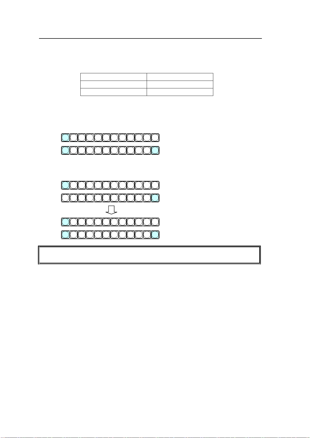
7-3-2. Using the SHIFT Function
Bus button 1
IN01
Bus button 1 (shifted)
STILL1
Bus button 12
SHIFT function
The SHIFT setting (NORMAL or TOGGLE) can be selected in the [SETUP - INPUT ASSIGN] (3/3) menu.
Press 1 while holding down 12 (SHIFT) to
select STILL1.
Press 1 to select IN01.
PGM
PST
1 2 3 4 5 6 7 8 9 10 11 12
Press 1 to select IN01.
Press 12 (SHIFT).
PGM
PST
1 2 3 4 5 6 7 8 9 10 11 12
Press 1 to select STILL 1.
PGM
PST
1 2 3 4 5 6 7 8 9 10 11 12
Once the SHIFT function has been assigned to a bus button, an additional 11 buttons are
available for signal selection.
This chapter explains how to select signals with the SHIFT button. Assume that video
sources and the shift function are assigned to bus buttons as shown in the table below:
Now, let's select IN01 on PGM and STILL1 on PST.
When SHIFT works in NORMAL mode:
Shifted buttons are enabled while holding down SHIFT.
When SHIFT works in TOGGLE mode:
To select shifted buttons, press SHIFT then press a bus button.
58
Page 59
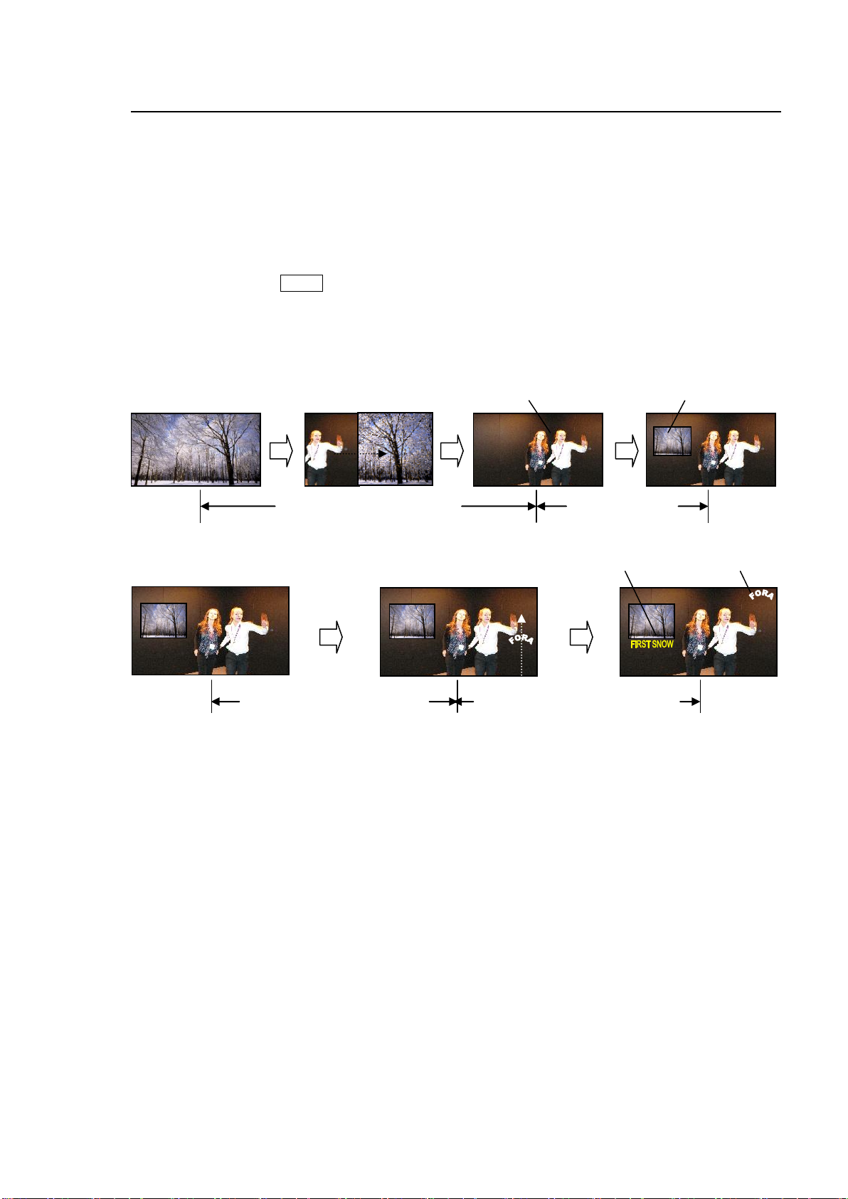
8. Transitions
Logo (DSK1) sliding in
Caption (DSK2)
Logo (DSK1)
Caption (DSK2) cutting in
Background pattern transition
KEY2 cutting in
KEY2
KEY1 (chromakey)
Available Transitions on the M/E (PGM/PST) bus
BLACK transition: MIX
Background: CUT, MIX and Pattern transitions
KEY1 and 2: CUT, MIX and Pattern transitions
SLIDE (4-direction), SCALER and WIPE (4-direction) transitions
DSK1 and 2: CUT and MIX transitions
SLIDE (4-direction), SCALER and WIPE (4-direction) transitions
-Transitions setup by next transition bus selection
-Transitions using the AUTO button or fader lever
-More than 130 types of various preset patterns
-Simultaneous background and key pattern transitions
Transition Example
Other Transitions
AUX crosspoint switching with effects
See section 6-1-3. "AUX Video Switching with Effects."
Transitions using Event Recall
See section15-5. "Transitions Using Event Recall."
59
Page 60
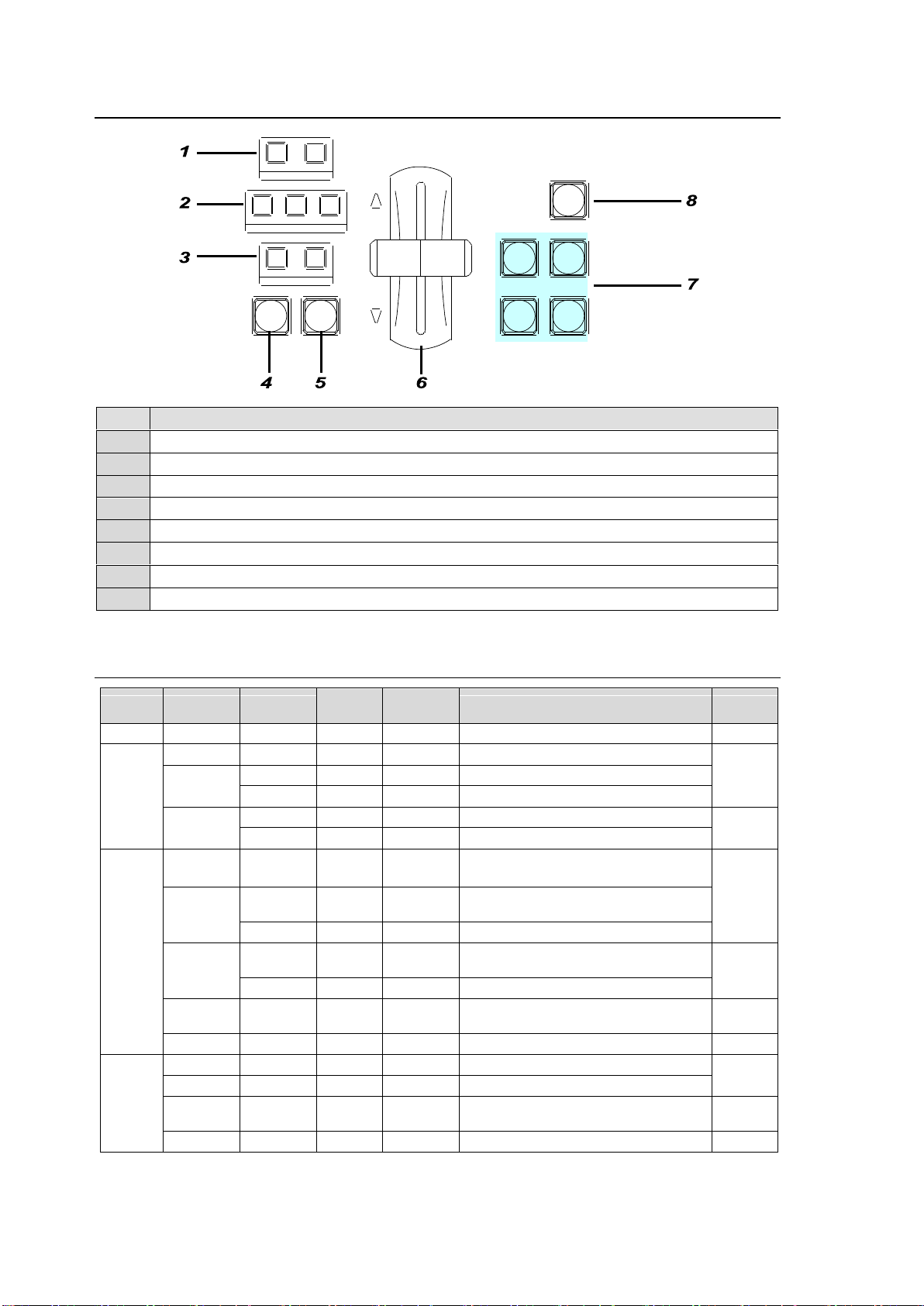
8-1. Transition Block Description
No.
Description
1
Pattern transition direction setting buttons
2
Next transition bus selection buttons
3
Transition type selection buttons for BKGD, KEY1 and KEY2
4
AUTO transition button for BKGD and KEY1 and KEY2
5
CUT transition button for BKGD and KEY1 and KEY2
6
Fader lever for performing BKGD, KEY1 and KEY2 transitions
7
KEY1, KEY2, DSK1 and DSK2 transition buttons
8
Black transition button
Bus
Type
Rate
Transitio
n Limit
Pattern
Direction
Transition Execute Button or Tool
Refer to
BLACK
BLACK
Available
-
-
BLACK TRANS button
8-6
BKGD
CUT
-
Available
-
BKGD >> CUT button
8-3
MIX
Available
Available
-
BKGD >> MIX >> AUTO button
--
Available
-
BKGD >> MIX >> Fader lever
WIPE
Available
Available
NOR/REV
BKGD >> WIPE >> AUTO button
8-3
8-8
-
Available
NOR/REV
BKGD >> WIPE >> Fader lever
KEY1
KEY2
CUT
-
Available
-
KEY >> CUT button
KEY1 and KEY2 transition buttons
8-4
MIX
Available
Available
-
KEY >> MIX >> AUTO (KEY1 and
KEY2 transition buttons)
--
Available
NOR/REV
BKGD >> MIX >> Fader lever
WIPE
Available
Available
NOR/REV
KEY >> WIPE>> AUTO (KEY1 and
KEY2 transition buttons)
8-4
8-8
-
Available
NOR/REV
KEY >> WIPE>> Fader lever
USER
TRANS
Available
-
-
Function-assigned user buttons
8-10
PRIORITY
- - -
Function-assigned user button
DSK1
DSK2
CUT
-
Available
-
DSK1 and DSK2 transition buttons
8-4
MIX
Available
Available
-
DSK1 and DSK2 transition buttons
USER
TRANS
Available
Available
-
Function-assigned user buttons
8-10
PRIORITY
- - -
Function-assigned user button
REV NOR/REV
DIRECTION
BLACK
TRANS
BKGD KEY1 KEY2
NEXT TRANSITION
MIX WIPE
KEY1 KEY2
TRANSITION TYPE
AUTO CUT DSK1 DSK2
8-2. Quick Reference for Available Transitions
60
Page 61
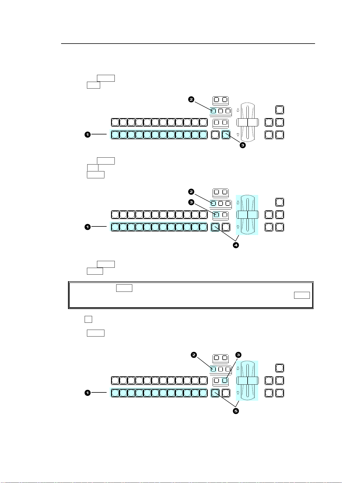
8-3. Background Transitions
If the light of the WIPE button does not turn on, a WIPE channel is already being used for
KEY1 or KEY2. In such case, change the KEY1 or KEY2 type to MIX, then press the WIPE
button again for the BKGD bus.
REV NOR/REV
DIRECTION
BLACK
TRANS
BKGD KEY1 KEY2
NEXT TRANSITION
MIX WIP E
KEY1 KEY2
TRANSITION TYPE
AUTO C UT DSK1 DSK2
PGM
PST
1 2 3 4 5 6 7 8 9 10 11 12
REV NOR/REV
DIRECTION
BLACK
TRANS
BKGD KEY1 KEY2
NEXT TRANSITION
MIX WIP E
KEY1 KEY2
TRANSITION TYPE
AUTO C UT DSK1 DSK2
PGM
PST
1 2 3 4 5 6 7 8 9 10 11 12
REV NOR/REV
DIRECTION
BLACK
TRANS
BKGD KEY1 KEY2
NEXT TRANSITION
MIX WIP E
KEY1 KEY2
TRANSITION TYPE
AUTO C UT DSK1 DSK2
PGM
PST
1 2 3 4 5 6 7 8 9 10 11 12
This chapter explains how to perform background transitions.
CUT Transition
(1) Select a video source in the PST bus block.
(2) Press the BKGD button in the NEXT TRANSITION block.
(3) Press CUT to perform the background CUT transition.
MIX Transition
(1) Select a video source in the PST bus block.
(2) Press the BKGD button in the NEXT TRANSITION block.
(3) Press MIX in the TRANSITION TYPE block.
(4) Press AUTO or move the fader lever to perform the background MIX transition.
WIPE Transition
(1) Select a video source in the PST bus block.
(2) Press the BKGD button in the NEXT TRANSITION block.
(3) Press WIPE in the TRANSITION TYPE block. The [TRANS] (1/6) menu is displayed.
(4)Turn F4 to select a desired pattern. (MIX, FAM and NAM transition types can be also
selected using Patterns 200 to 202.")
(5) Press AUTO or move the fader lever to perform the background WIPE transition.
61
Page 62

See section 8-8. "Pattern (WIPE) Transitions" for the WIPE transition details.
See section 8-11-2. "Transition Rate" for the transition rate.
See section 8-11-3. "Transition Limit" for the transition limit.
To Check Next Video:
To check the Preview video, assign the Preview video to an AUX bus to display the image.
See section 6-2. "Preview Set Up."
To check the clean video, assign the Clean video to an AUX bus to display the program video
clear signal.
See section 6-3. "Clean Set Up."
62
Page 63
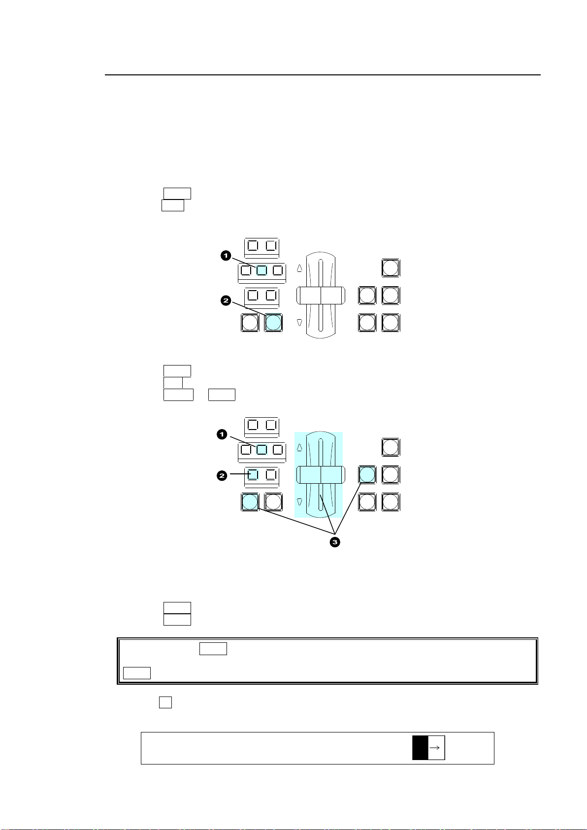
8-4. KEY Transitions
If the light of the WIPE button does not turn on, a WIPE channel is already being used for
BKGD or KEY2. In such case, change the BKGD or KEY2 type to MIX, then press the
WIPE button again for KEY1.
TRANS : RATE :TRANS LIMIT :PAT NO : 1/6
BKGD : =30 :=100.0 =OFF : =0 :
REV NOR/REV
DIRECTION
BLACK
TRANS
BKGD KEY1 KEY2
NEXT TRANSITION
MIX WIPE
KEY1 KEY2
TRANSITION TYPE
AUTO CUT DSK1 DSK2
REV NOR/REV
DIRECTION
BLACK
TRANS
BKGD KEY1 KEY2
NEXT TRANSITION
MIX WIPE
KEY1 KEY2
TRANSITION TYPE
AUTO CUT DSK1 DSK2
Key images are displayed on the M/E (background) output screen. This chapter explains how to
perform key transitions using KEY1 as an example.
1. Perform key setup for KEY1.
See section 9. "KEY/DSK."
2. Perform a desired transition referring to the below procedures.
CUT Transition
(1) Press KEY1 in the NEXT TRANSITION block.
(2)Press CUT to perform a key CUT transition. KEY1 will be inserted onto the program video.
Press the button again to remove KEY1 from the screen.
MIX Transition
(1) Press KEY1 in the NEXT TRANSITION block.
(2) Press MIX in the TRANSITION TYPE block.
(3) Press AUTO or KEY1 or move the fader lever to perform the KEY1 MIX transition.
Pattern transition
(1) Press KEY1 in the NEXT TRANSITION block.
(2) Press WIPE in the TRANSITION TYPE block. The [TRANS](1/6) menu is displayed.
(3) Turn F4 to select a desired pattern. (Note that only one pattern can be set at the same
time.)
63
Page 64
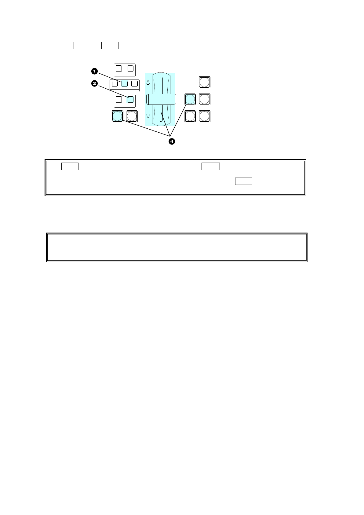
The KEY1 transition button behaves the same as the AUTO button when selecting KEY1
for the next transition. For example, if MIX is set as the KEY1 transition type under the
NEXT TRANSITION, the KEY1 mix transition is performed when KEY1 is pressed and a
KEY1 wipe transition is performed if WIPE is set as the transition type.
Note that when performing pattern transitions with a DVE pattern (No. 100 -137) for KEY1
or KEY2, all 2D DVE menu settings are disabled.
See section 9-8 "DVE Effect on KEY/DSK."
REV NOR/REV
DIRECTION
BLACK
TRANS
BKGD KEY1 KEY2
NEXT TRANSITION
MIX WIPE
KEY1 KEY2
TRANSITION TYPE
AUTO CUT DSK1 DSK2
(4) Press AUTO or KEY1, or move the fader lever to perform the pattern transition.
See section 8-8. "Pattern (WIPE) Transitions" for details on WIPE transitions.
See section 8-11-2. "Transition Rate" for details on the transition rate.
See section 8-11-3. "Transition Limit" for details on the transition limit.
USER Transition
Press a user button, to which a KEY1 effect transition (scaler, slide in/out, etc.) is assigned, to
insert the KEY1 image on the M/E program video.
See section 8-10-2. "USER Transitions" for details.
64
Page 65
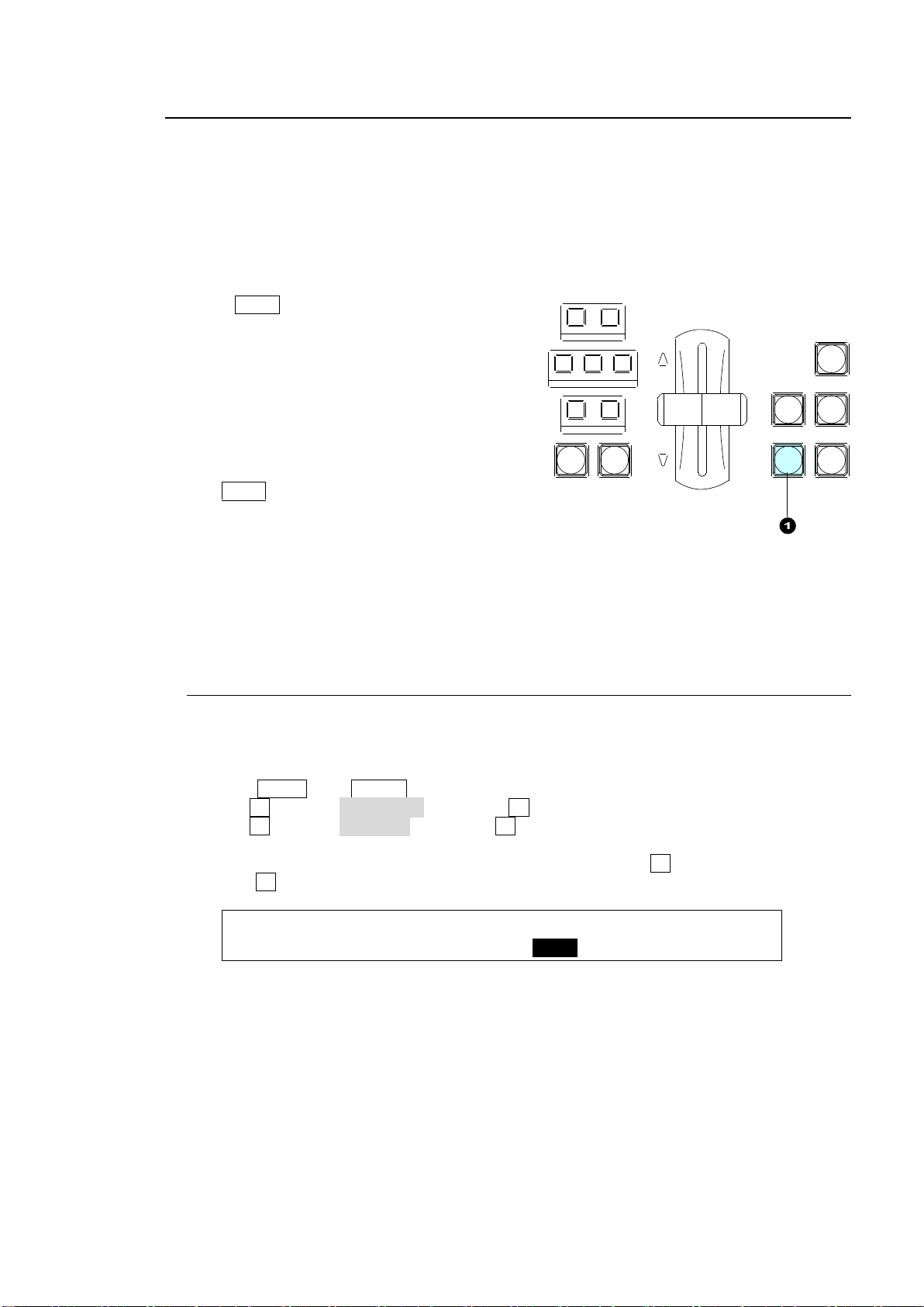
8-5. DSK Transitions
FUNCTION:TRSEDGE:KEY LNK: DSK ASSIGN : 1/1
M/E KEY : =ON : =ON :1=AUX1 2=M/E :
REV NOR/REV
DIRECTION
BLACK
TRANS
BKGD KEY1 KEY2
NEXT TRANSITION
MIX WIPE
KEY1 KEY2
TRANSITION TY PE
AUTO CUT DSK1 DSK2
DSK images are displayed on the M/E (background) or an AUX output screen. This chapter
explains how to perform DSK transitions using DSK1 as an example.
See section 8-5-1. "Where DSK Images Appear."
1. Perform key setup for the DSK1.
See section 9. "KEY/DSK."
2. Perform a desired transition referring to the below procedures.
MIX Transition
Press DSK1.
The transition rate can be set.
See section 8-11-2. Transition Rate."
CUT transitions are also available.
See section 8-10. "KEY/DSK Transitions."
The DSK1 button can also perform CUT transitions
by changing the button function in the menu.
See section 8-10-1."Setting the KEY/DSK Transition Button Function."
USER Transition
Press a user button, to which a DSK1 effect transition (scaler, slide in/out, etc.) is assigned, to
insert the DSK1 image on the M/E program video.
See section 8-10-2. "USER Transitions" for details.
8-5-1. Where DSK Images Appear
The DSK1 and DSK2 images appear on the program screen as a factory default setting.
Users can change the destination of DSK images to AUX1 to 8. To do this, follow the
procedure below.
(1) Press MENU, then SETUP in the SELECT/KEYPAD block to display the [SETUP] menu.
(2) Turn F1 to select FUNCTION, and press F1 to open the [SETUP - FUNCTION] menu.
(3) Turn F1 to select M/E_KEY, and press F1 to open the [SETUP - FUNCTION - M/E KEY]
menu.
(4) To display the DSK1 image on the AUX1 program video, turn F3 to select AUX1 and then
press F3. Select the destination for DSK2 in the same way.
65
Page 66
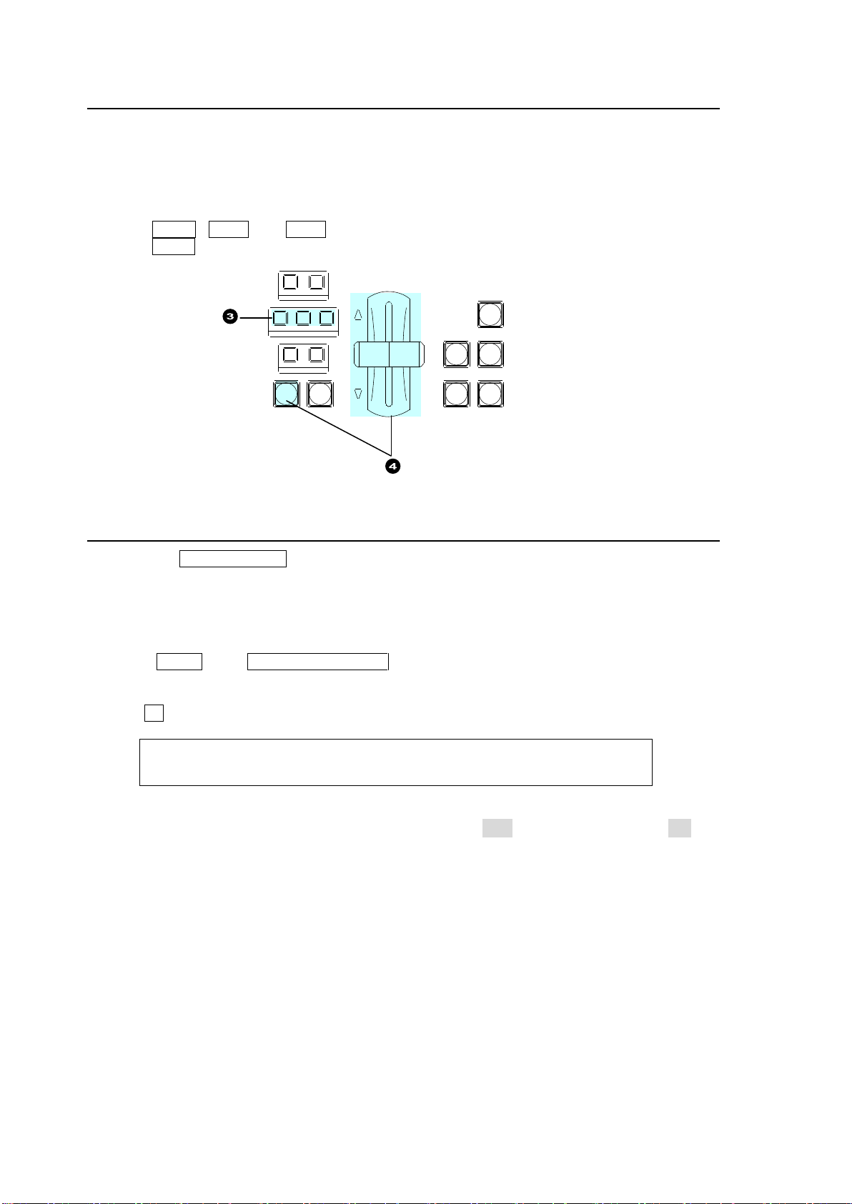
8-6. Simultaneous BKGD and Key Transitions
TRANS : RATE :ENABLE : : 6/6
BLACK : =30 : =ON : :
REV NOR/REV
DIRECTION
BLACK
TRANS
BKGD KEY1 KEY2
NEXT TRANSITION
MIX WIPE
KEY1 KEY2
TRANSITION TYPE
AUTO CUT DSK1 DSK2
Background and key transitions can be performed simultaneously. This chapter explains how to
perform simultaneous BKGD, KEY1 and KEY2 transitions as an example.
(1) Set transition types for the background, KEY1 and KEY2 to MIX or WIPE, respectively.
Select a pattern using the menu if set to WIPE.
(2) Set the transition rate or direction, if necessary.
(3) Press BKGD, KEY1 and KEY2 simultaneously to turn on the button lights.
(4) Press AUTO, or move the fader lever to perform a simultaneous transition.
8-7. Black Transitions
Pressing the BLACK TRANS button allows BLACK transitions to be performed. Pressing the
button initiates a fade to black of whichever source is currently on air (program output). Pressing
the button again starts another fade from black to the previous video.
BLACK transitions can be performed on the PGM output.
To Set the Black Transition Rate
(1) Press MENU then TRANSITION RATE in the SELECT/KEYPAD block to display the
[TRANS] menu.
(2) Press the page down button to go to PAGE 6.
(3) Turn F1 to set the transition rate in frames for BLACK transitions.
To Disable the BLACK TRANS button:
Set the ENABLE item in the [TRANS] (6/6) menu above to OFF. (The default setting is ON.)
66
Page 67
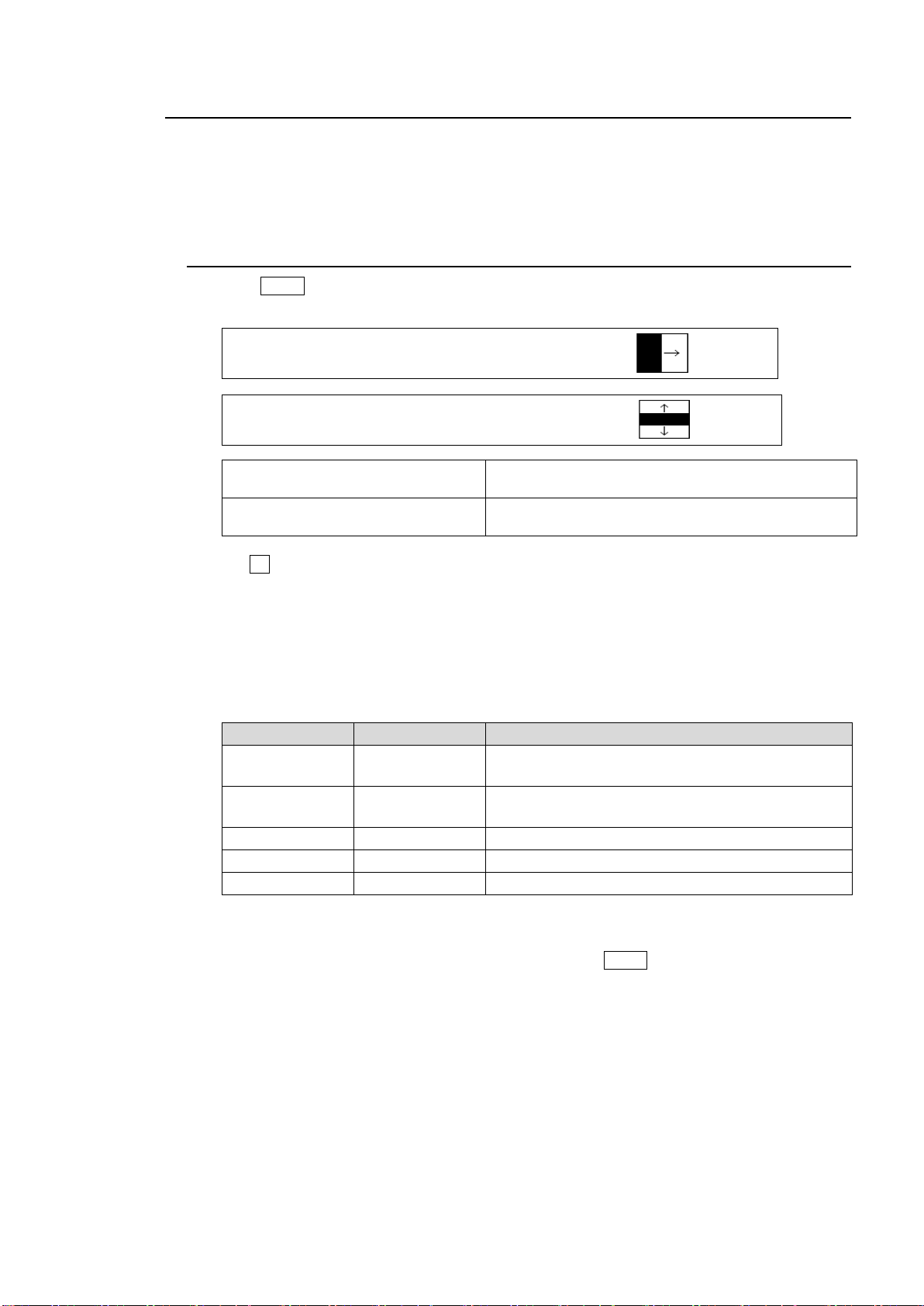
8-8. Pattern (WIPE/DVE) Transitions
TRANS : RATE :TRANS LIMIT :PAT NO : 1/6
BKGD : =30 :=100.0 =OFF : =0 :
TRANS : RATE :TRANS LIMIT :PAT NO : 1/6
BKGD : =30 :=100.0 =OFF := M20 :
Numbers starting with the letter M:
Indicates modified patterns.
See section 8-9. "Modifying Patterns."
Numbers starting with the letter C:
Indicates the pattern is being used by CG WIPE.
See section 12-5. "CG WIPE."
Pattern No.
Type of Group
Available modification settings
0 to 99
WIPE
2D border, multi, 2D position, 2D size, etc.
See "Appendix 2."
100 to 137
DVE
(2D DVE)
2D border, 2D position, 2D size, crop, etc.
See "Appendix 2."
200
MIX
Performs MIX transitions.
201
FAM
Performs Full-Additive Mix transitions.
202
NAM
Performs Non-Additive Mix transitions.
Pattern transitions are available for Background, KEY1 and KEY2.
See section 8-3. "Background Transitions."
See section 8-4. "KEY Transitions."
This chapter explains details on the pattern selection method and transition direction.
8-8-1. Selecting a Pattern
(1) Press WIPE in the transition block to display the [TRANS] (1/6) menu. The pattern
number and thumbnail will be displayed as shown in the menus below.
(2) Turn F4 to select a pattern.
The Direct Pattern function allows users to select patterns quickly.
See section 8-8-3. "Direct Pattern Function."
Available Patterns are:
There are two types of preset patterns: WIPE and DVE.
MIX, FAM or NAM can also be elected as pattern types.
Only one pattern can be selected for all BKGD, KEY1 and KEY2 buses.
Note that if WIPE is set for a bus, WIPE cannot be set for another bus. In such case, cancel
WIPE by selecting MIX for the current bus, then press the WIPE button again for the desired
bus.
67
Page 68

8-8-2. Use Limitations for Pattern Transitions
When using a WIPE type pattern (0-99):
Pattern transitions cannot be simultaneously performed both on KEY1 and KEY2.
If both KEY1 and KEY2 pattern transitions are performed, one transition is automatically
changed to MIX.
When using a DVE type pattern (100-137):
Either BKGD, KEY1 or KEY2 bus can perform pattern transitions.
If the WIPE type cannot be set, a DVE pattern must be assigned to another bus. Deselect
WIPE in another bus and set WIPE again for the bus.
Note that 2D DVE menu settings are all disabled while a pattern transition is being performed
on KEY1 or KEY2.
See section 9-8. "DVE Effects on KEY/DSK."
If 2D DVE is enabled on all four key buses, KEY1, KEY2, DSK1 and DSK2, BKGD pattern
transitions cannot be performed. In such case, set 2D DVE to OFF on any bus. Then press
WIPE again for BKGD.
See section 9-8-1. "How to Enable 2D DVEs."
When using FAM (Pattern 201) or NAM (Pattern 202):
FAM or NAM transitions cannot be performed on KEY1 and KEY2. If selecting Pattern 201 or
202 for a key, transitions are performed with MIX instead FAM or NAM.
68
Page 69
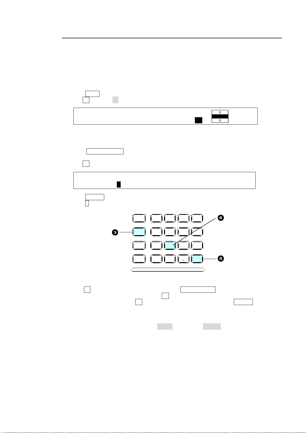
8-8-3. Direct Pattern Function
TRANS : RATE :TRANS LIMIT :PAT NO : 1/6
BKGD : =30 :=100.0 =OFF : =20 :
DIRECT : PAGE :DIRECT :CLEAR : : 1/1
PATTERN : =0 : =ON : >OFF : :
MENU ATTACH
DIRECT
PATT
DETACH
SETUP
KEY1
8 9
4 5 6
STILL MATT F ILE
KEY2 DSK1 DSK2
EVENT
MACRO
1 2 3
0
CLEAR
RECALL ST ORE
ENTER
CK EFF ECT
TRANS RAT E WIPE
SELECT /KEYPAD
±
7
The Direct Pattern Selection feature allows users to select a pattern easily and quickly.
The feature uses the number buttons on the keypad (0-9), to which WIPE patterns previously
registered can be recalled at the touch of a button. Up to 20 patterns can be registered as
direct patterns under two pages (PAGE 0 and PAGE 1).
As an operational example, let's save Pattern 20 to the Direct Pattern memory and load it to a
WIPE transition.
To Register Pattern 20 to Button 1 (PAGE 0):
(1) Press WIPE in the transition block to display the [TRANS] (1/6) menu.
(2) Turn F4 to select 20.
Modify the pattern, if necessary.
See section 8-9 "Modifying Patterns."
(3) Press DIRECT PATT on the left side of the SELECT/KEYPAD block to display the
[DIRECT PATTERN] menu. The keypad also changes to DIRECT PATTERN mode.
(4) Turn F1 to select PAGE 0, if it is not selected.
(5) Press STORE in the Keypad.
(6) Press 1 in the Keypad.
If a Pattern is already Saved to Button 1:
If Button 1 is lit in the keypad when pressing the DIRECT PATT button, another pattern has
already been saved to the button. Press 1 . The button will blink. To overwrite the current
pattern with Pattern 20, press 1 again. To cancel the overwrite, press STORE. To save to
another button, press an unregistered button.
If users cannot overwrite a number button (lit red), cancel the operation and change the
OVER WR (overwrite) parameter from DISBL (disable) to ENABL (enable) in the [DIRECT
RECALL] menu. The [DIRECT RECALL] menu is automatically displayed when the number
button to which a pattern is stored on the keypad is pressed.
69
Page 70
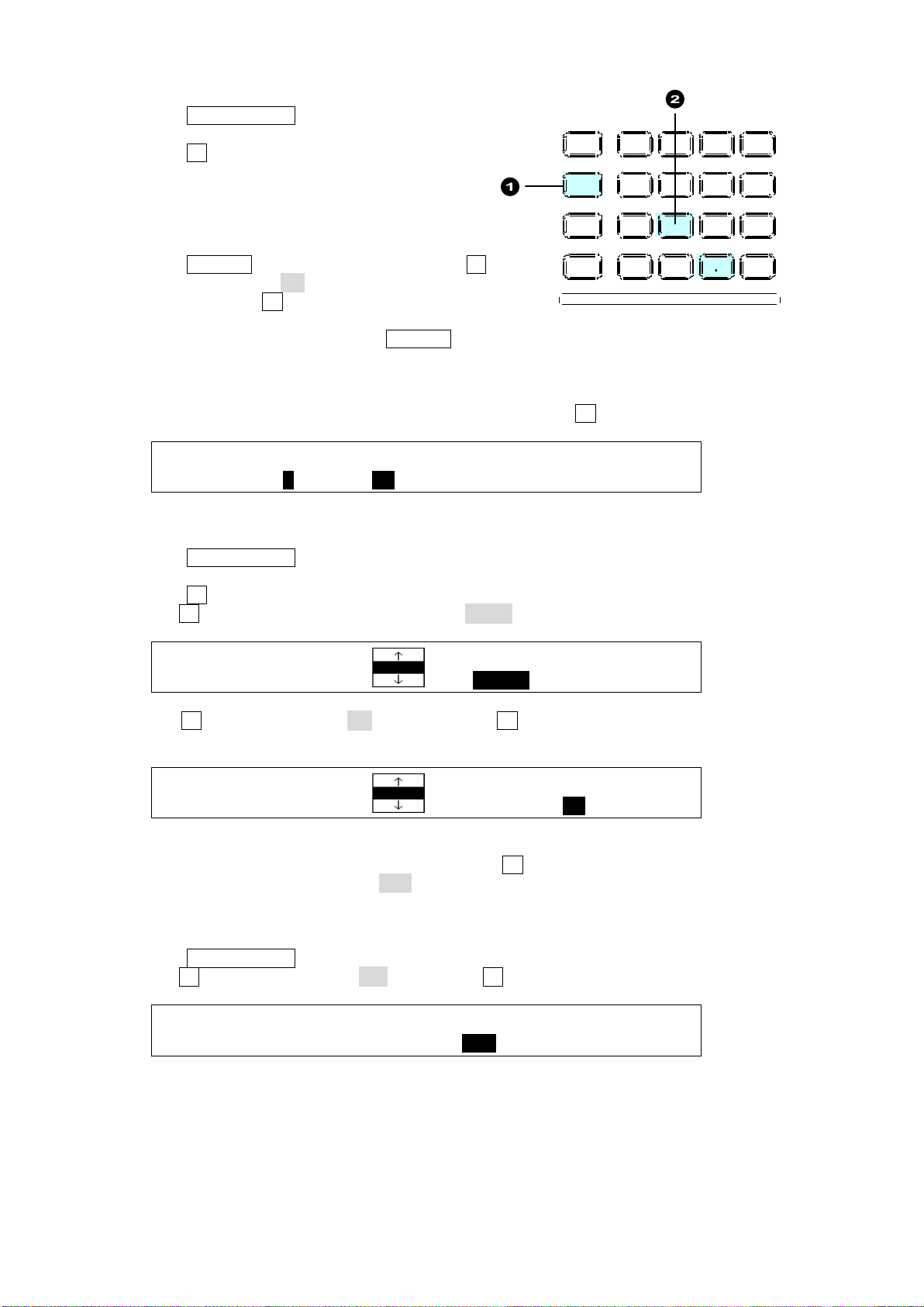
To Select Pattern 20:
DIRECT : PAGE :DIRECT :CLEAR : : 1/1
PATTERN : =0 : =ON : >OFF : :
DIRECT :PATTERN :OVER WR:DELETE : 1/1
RECALL : =020 : =DISBL: >OFF :
DIRECT :PATTERN :OVER WR:DELETE : 1/1
RECALL : =020 : =ENABL: >ON :
DIRECT : PAGE :DIRECT :CLEAR : : 1/1
PATTERN : =0 : =OFF : >ALL : :
MENU ATTACH
DIRECT
PATT
DETACH
SETUP
KEY1
8 9
4 5 6
STILL MATT F ILE
KEY2 DSK1 DSK2
EVENT
MACRO
1 2 3
0
CLEAR
RECALL ST ORE
ENTER
CK EFF ECT
TRANS RAT E WIPE
SELECT /KEYPAD
±
7
(1) Press DIRECT PATT to change the keypad
to DIRECT PATTERN mode.
(2) Press 1 on the Keypad. Pattern 20 will be
selected and the transition type is automatically
switched to WIPE.
If Pattern 20 is not selected…
Press RECALL on the keypad after pressing 1 .
If DIRECT is set to ON in the [DIRECT PATTERN]
menu by turning F2,Direct Recall mode is
enabled and patterns can be recalled by pressing
number buttons (without pressing RECALL.)
If another pattern is selected…
PAGE 1 is assumed to be selected.
Select PAGE 0 in the [DIRECT PATTERN] menu by turning F1.
To Set Overwrite Protection or Delete the Data
(1) Press DIRECT PATT to change the keypad mode.
(2) Verify that PAGE0 is selected.
(3) Press 1 on the Keypad. The [DIRECT RECALL] menu will be displayed.
(4) Turn F3 to change OVER WR (Overwrite) to DISBL (Disable) to set overwrite protection.
Turn F4 to set DELETE to ON and then press F4. The data will be deleted from the
button.
In the procedure above, Pattern 20 is recalled when 1 is pressed. To prevent the pattern,
from being recalled, set DIRECT to OFF in the menu before recalling the event, then press
the number button.
To Clear All Direct Pattern Registrations
(1) Press DIRECT PATT to change the keypad mode.
(2) Turn F3 to change CLEAR to ALL. Then press F3 to clear all direct patterns.
70
Page 71

8-8-4. Other Transition Settings
Transition direction
NOR/REV button
REV button
Always Normal
Unlit
Unlit
Always Reverse
Unlit
Lit
Normal at Normal/Reverse operation
Lit
Unlit
Reverse at Normal/Reverse operation
Lit
Lit
Transition Direction
Two direction buttons (NOR/REV, REVERSE) are used to set the pattern transition direction
as shown in the table below.
Transition Rate
The AUTO transition duration (Transition Rate) can be set in the menu.
See section 8-11-2. "Transition Rate."
Transition Limit
When performing transitions there may be times when you want the transition to the next
signal to only complete to a certain degree instead of fully switching from one picture to
another. In such case, change the Transition Limit setting in the menu.
See section 8-11-3. "Transition Limit."
71
Page 72

8-9. Modifying Patterns
Pattern No.
Type of Group
Available modification settings
0 to 99
WIPE
2D border, multi, 2D position, 2D size, etc.
100 to 137
DVE (2D DVE)
2D border, 2D position, 2D size, crop, etc.
TRANS : RATE :TRANS LIMIT :PAT NO : 1/6
BKGD : =30 :=100.0 =OFF : =M0 :
WIPE :>BORDER >POS/ANGL>MULTI >CG WIPE
No.0XX :>INIT
WIPE :SIGNAL : WIDTH : SOFT : : 1/2
BORDER : =MATT : =0.0 : =0.0 : :
WIPE : BORDER COLOR :RECALL : 2/2
BORDER :S=66.3 L=5.4 H=3.5 : >WHITE:
WIPE : POSITION : ANGLE :ASPECT : 1/1
POS/ANGL:X=0 Y=0 : =0.0 : =0.0 :
WIPE : MULTI : : 1/1
MULTI :X=1 Y=1 : :
WIPE : INIT : : 1/1
INIT : >OFF : :
Preset patterns can be modified using the WIPE menu. Two pattern types are available: WIPE
and DVE. Each type has its own menu pages.
If a pattern is modified, the pattern number starts with the letter "M" in the [TRANS](1/6) menu as
shown below.
The following chapters explain how to modify patterns using the background and KEY1 as
examples.
8-9-1. WIPE Type (No. 0-99)
WIPE menu
The pattern number is displayed instead of "0XX" in the top page of the submenu.
See section 12-5-3. "CG WIPE Menu Quick Reference" for details on CG WIPE pages.
72
Page 73
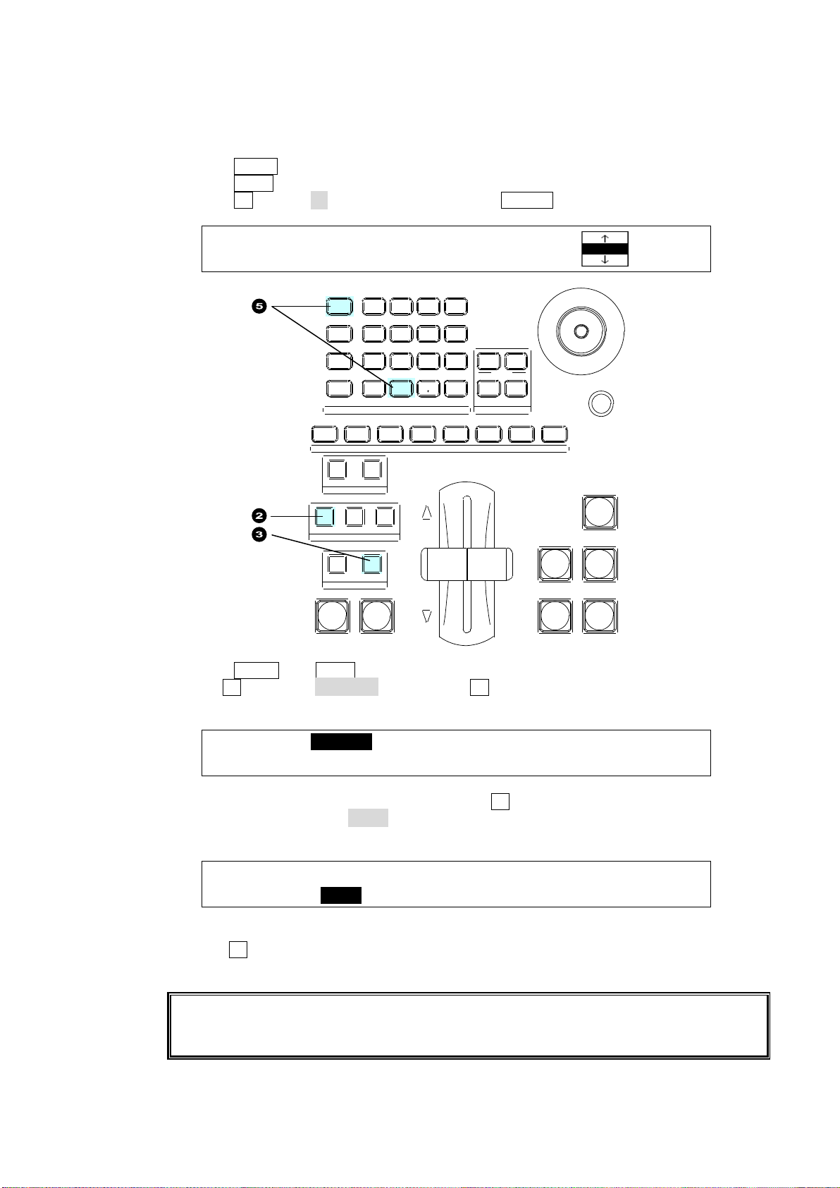
Modify Pattern 20
TRANS : RATE :TRANS LIMIT :PAT NO : 1/6
BKGD : =30 :=100.0 =OFF := 20 :
WIPE :>BORDER >POS/ANGL>MULTI >CG WIPE
No.020 :>INIT
WIPE :SIGNAL : WIDTH : SOFT : : 1/2
BORDER : =MATT : =5.0 : =2.0 : :
Modified pattern data is lost when the switcher is powered off. In addition, any modified
data is fully or partly lost when another pattern is selected. It is recommended that
important modified patterns be registered to Direct Patterns.
SIZE
(PUSH to DEF)
1 2 3 4 5 6 7 8
USER BUTTON
REV NOR/REV
DIRECTION
BLACK
TRANS
BKGD KEY1 KEY2
NEXT TRANSITION
MIX WIPE
KEY1 KEY2
TRANSITION TY PE
AUTO CUT DSK1 DSK2
MENU AT T ACH
DIRECT
PATT
DETACH
SETUP
KEY1
POSITION
POS ROT
2D DVE
WIPE
POS
MENU
JOYSTICK
8 9
4 5 6
STILL MA TT FI LE
KEY2 DS K1 DSK 2
EVENT
MACRO
1 2 3
0
CLEAR
RECALL STORE
ENTER
CK EFF ECT
TRANS RATE WIPE
SELECT/KEYPAD
±
7
This modification example adds a border to the background transitions using Pattern 20.
(1) Select a desired signal on the PST bus.
(2) Press BKGD in the NEXT TRANSITION block.
(3) Press WIPE. The [TRANS] (1/6) menu is displayed.
(4) Press F4 to enter 20 in the keypad, then press ENTER.
(5) Press MENU,then WIPE in the SELECT/KEYPAD block to display the [WIPE] menu.
(6) TurnF1 to select BORDER, then press F1 or the page down button to display the
submenu.
(7) The [WIPE - BORDER] menu appears. Turn F1 to select the signal used for the border
under SIGNAL. Select MATT in this example. Set the border width under WIDTH and
border softness under SOFT.
(8) Press the page down button to go to PAGE 2.
(9) Turn F4 to select a border color among eight standard colors.
See section 5-9-1. "Setting the Matte Color" for details on color setting.
73
Page 74
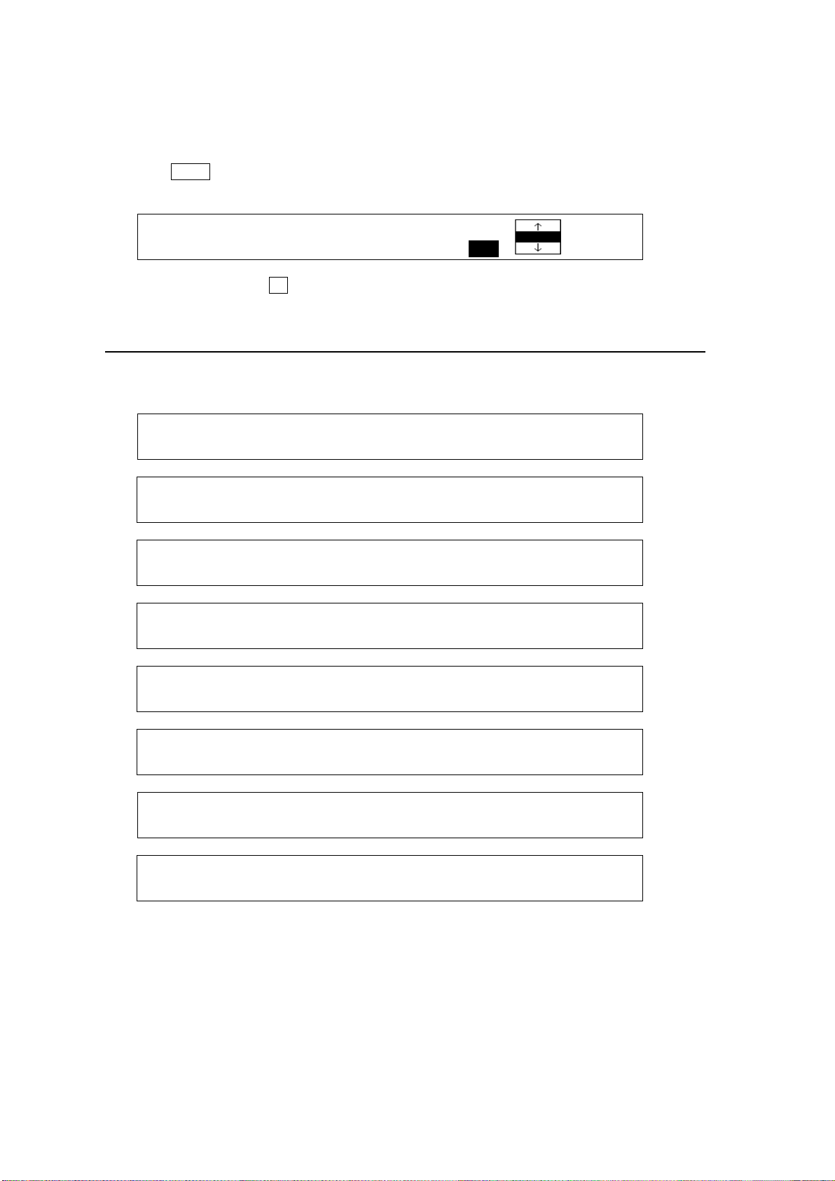
To Register the Modified Pattern to a Direct Pattern:
TRANS : RATE :TRANS LIMIT :PAT NO : 1/6
BKGD : =30 :=100.0 =OFF := M20 :
WIPE :>BORDER >POS/ASP >CROP >CG WIPE
No.1XX :>INIT
WIPE : INSIDE : OUTSIDE : 1/3
BORDER :X=0 Y=0 :X=0 Y=0 :
WIPE : INSIDE :OUTSIDE: : 2/3
BDR SOFT:X=0 Y=0 : =0 : :
WIPE : BORDER COLOR :RECALL : 3/3
BDR COL :S=0.0 L=100.0 H=0.0 : >WHITE:
WIPE : POSITION : SIZE : : 1/2
POS/SIZE:X=0 Y=0 : =1000 : :
WIPE : ASPECT :FADE LV: : 2/2
ASPT/FAD:X=1000 Y=1000 : =0.0 : :
WIPE : CROP POSITION : 1/1
CROP :T=0.0 B=0.0 L=0.0 R=0.0 :
WIPE : INIT : : 1/1
INIT : >OFF : :
Refer to section 8-8-3. "Direct Pattern Function" to save a modified pattern to a direct
pattern.
To Reset the Modified Pattern:
(1) Press WIPE in the transition block to display the [TRANS] (1/6) menu. The letter "M"
(Modified) will be displayed in front of 20.
(2) Press and hold down F4. Pattern 20 will be reset to its default settings.
8-9-2. DVE Type (No. 100-137)
WIPE menu
The pattern number is displayed instead of "1XX" in the top page of the submenu.
See section 12-5-3 "CG WIPE Menu Quick Reference" for details on CG WIPE pages.
74
Page 75
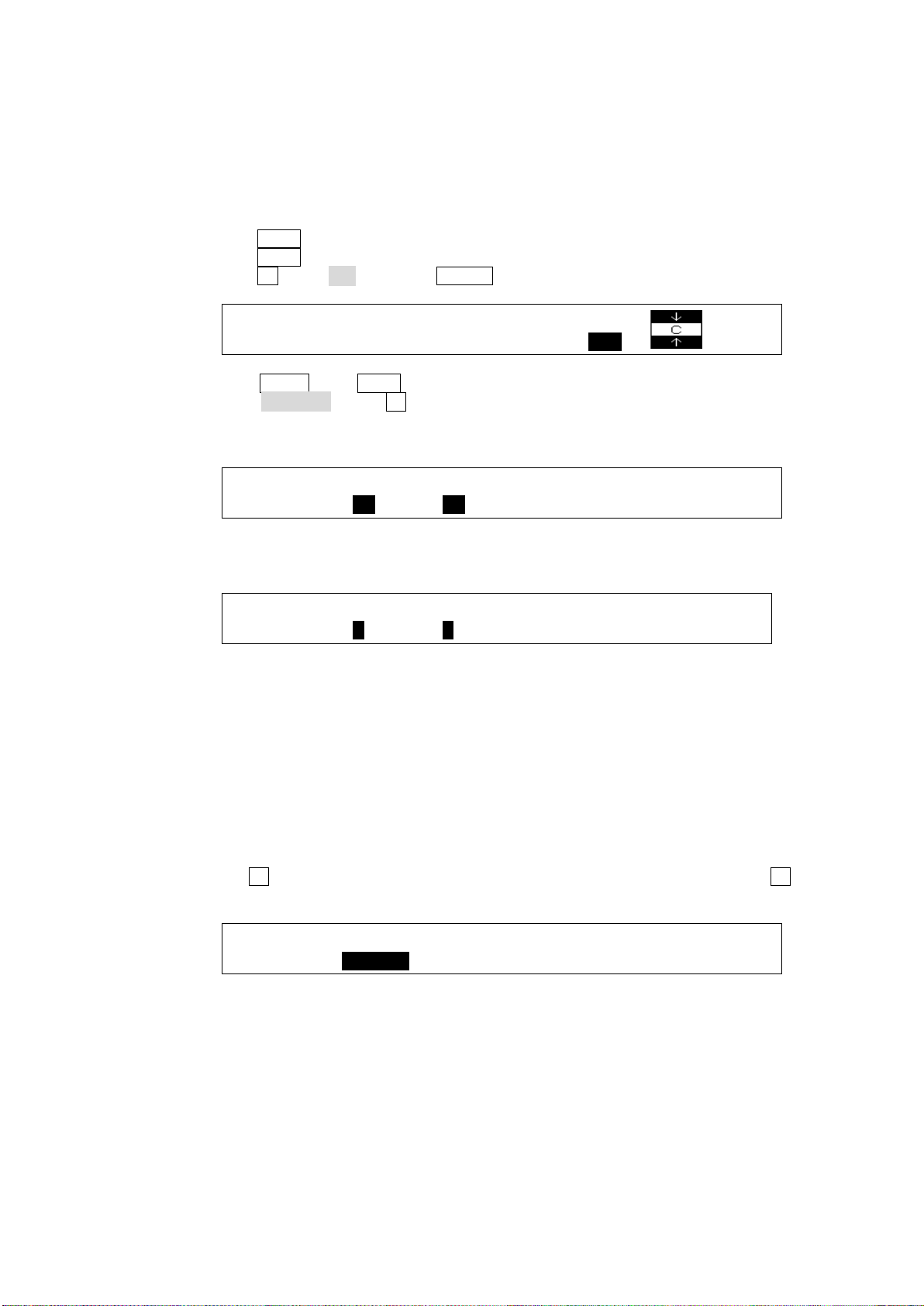
Modify Pattern 117
TRANS : RATE :TRANS LIMIT :PAT NO 1/6
BKGD : =30 :=100.0 =OFF := 117
WIPE : INSIDE : OUTSIDE : 1/3
BORDER :X=20 Y=50 :X=0 Y=0 :
WIPE : INSIDE :OUTSIDE: : 2/3
BDR SOFT:X=3 Y=3 : =0 : :
WIPE : INIT : : 1/1
INIT :>BORDER: :
This modification example also adds a border effect to KEY1 transitions using Pattern 117.
However Pattern 117 has different border settings than Pattern 20, and can be used for both
inside and outside border effects.
(1) Set up KEY1.
See section 9. "KEY/DSK."
(2) Press KEY1 in the NEXT TRANSITION block.
(3) Press WIPE. The [TRANS](1/6) menu is displayed.
(4) Press F4, enter 117 and press ENTER in the Keypad.
(5) Press MENU, then WIPE in the SELECT/KEYPAD block to display the [WIPE] menu.
Select BORDER. Press F1 or the page down button.
(6) An inside border is added in this example. To add a border, set the border width under
INSIDE X and Y.
(7) Press the page down button to go to PAGE 2. Set the softness for the inside border under
INSIDE X and Y.
(8) Press the page down button to go to PAGE 3 and set the border color.
See section 5-9-1. "Setting the Matte Color."
To Register the Modified Pattern to a Direct Pattern:
Refer to section 8-8-3. "Direct Pattern Function" to save the modified pattern to a direct
pattern.
To Fully or Partly Reset the Modified Pattern:
The INIT parameter allows the user to reset a submenu respectively in the WIPE menu.
(1) Display the [WIPE - INIT] menu.
(2) Turn F1 to select the parameter group you want to reset. Press and hold down F1 to reset
the selected parameter values.
75
Page 76
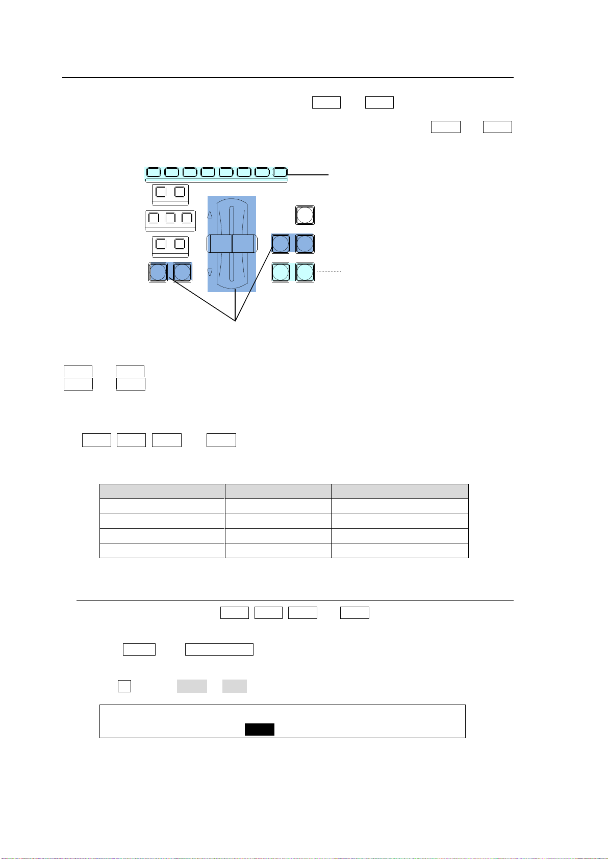
8-10. KEY/DSK Transitions
Transition state
Output bus
Transition button indication
On-Air
M/E
Lit red
On-Air (DSK1-2)
AUX1-8
Lit green
Transition
---
Flashing
Off-Air
---
Unlit
TRANS : RATE :ADV CTL: TRANS LIMIT : 2/6
KEY1 : =30 : =AUTO : =100.0En=OFF :
For KEY1 and KEY2
transitions
For DSK1 and DSK2
transitions
KEY1-2 and DSK1-2 transitions
possible if transition functions are
assigned.
1 2 3 4 5 6 7 8
USER BUTTON
REV NOR/REV
DIRECTION
BLACK
TRANS
BKGD KEY1 KEY2
NEXT TRANSITION
MIX WIPE
KEY1 KEY2
TRANSITION TYPE
AUTO CUT DSK1 DSK2
KEY1 and KEY2 transitions can be performed not only through the BKGD AUTO button and
fader lever, but also through key transition buttons (KEY1 and KEY2 in the transition section)
and user buttons, to which key transition functions are assigned.
DSK1 and DSK2 transitions can be performed through DSK transition buttons (DSK1 and DSK2
in the transition section) and user buttons, to which DSK transition functions are assigned.
KEY1 and KEY2 transition buttons can perform CUT and AUTO (MIX and WIPE) transitions.
DSK1 and DSK2 transition buttons can perform CUT and MIX transitions.
Key or DSK transitions such as CUT, MIX, SCALER, SLIDE (4 types) and WIPE (4 types) can
be assigned to user buttons.
KEY1, KEY2, DSK1 and DSK2 Transition Button Light Indications
The transition buttons turn on while On-Air and turn off when Off-Air.
The light-up color of DSK buttons indicates the output destination (M/E or AUX bus).
8-10-1. Setting the KEY/DSK Transition Button Function
Transition button functions for KEY1, KEY2, DSK1 and DSK2 are set in the menu as shown
below.
(1) Press MENU, then TRANS RATE in the SELECT/KEYPAD block to display the [TRANS]
(1/6) menu.
(2) Press the page down button to go to PAGE 2 in case of KEY1.
(3) Turn F2 to select AUTO or C/AT.
76
Page 77
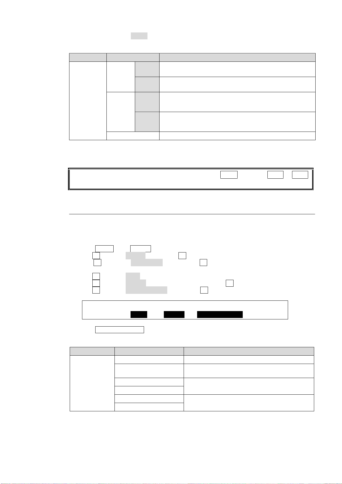
The buttons are set to AUTO as factory default. The transition buttons function as shown in
Parameter
Setting
Description
ADV CTL
AUTO
(default)
KEY1
KEY2
Always performs AUTO transitions regardless of how long
the button is pressed.
DSK1
DSK2
Always performs MIX transitions regardless of how long the
button is pressed.
C/AT
KEY1
KEY2
Performs Cut transitions when button is briefly pressed.
Performs AUTO transitions when button is pressed and
held down.
DSK1
DSK2
Performs Cut transitions when button is briefly pressed.
Performs MIX transitions when button is pressed and held
down.
OFF
Disables the button function.
Note that users can perform key transitions by pressing AUTO as well as KEY1 or KEY2.
See section 8-4. "KEY Transitions."
USER :SELECT : TYPE : FUNC(F3) : 1/2
BUTTON : =OU-3 : =USTRS: =DSK1 SCALER
TYPE Setting
FUNC Setting
Description
USTRS (User
Transition)
CUT
Cuts images in or out.
SCALER
Scales up to insert images or scales down to
remove images.
SLIDE RIGHT/LEFT
Slides in to insert images or slides out to remove
images.
SLIDE TOP/BOTTOM
WIPE RIGHT/LEFT
Wipes images in or out.
WIPE TOP/BOTTOM
the table below.
The transition time can be set under RATE in each [TRANS] menu.
See section 8-11-2. "Transition Rate" for details.
8-10-2. USER Transitions
The Key and DSK transition functions can be assigned to user buttons. This chapter explains
how to assign functions to buttons by assigning DSK1 SCALER to USER BUTTON 3 as an
example.
(1) Press MENU, then SETUP in the SELECT/KEYPAD block to display the menu.
(2) Turn F1 to select PANEL, then press F1 to display the [SETUP - PANEL] menu.
(3) Turn F1 to select USER BTN, then press F1 to display [SETUP - PANEL - USER
BUTTON] (1/2) menu.
(4) Turn F1 to select OU-3 (USER BUTTON 3).
(5) Turn F2 to select USTRS (User Transition), then press F2.
(6) Turn F3 to select DSK1 SCALER, then press F3.
(7) Press USER BUTTON 3 to perform the DSK1 transition.
Avilable User Transitions
See section 14. "User Buttons."
77
Page 78
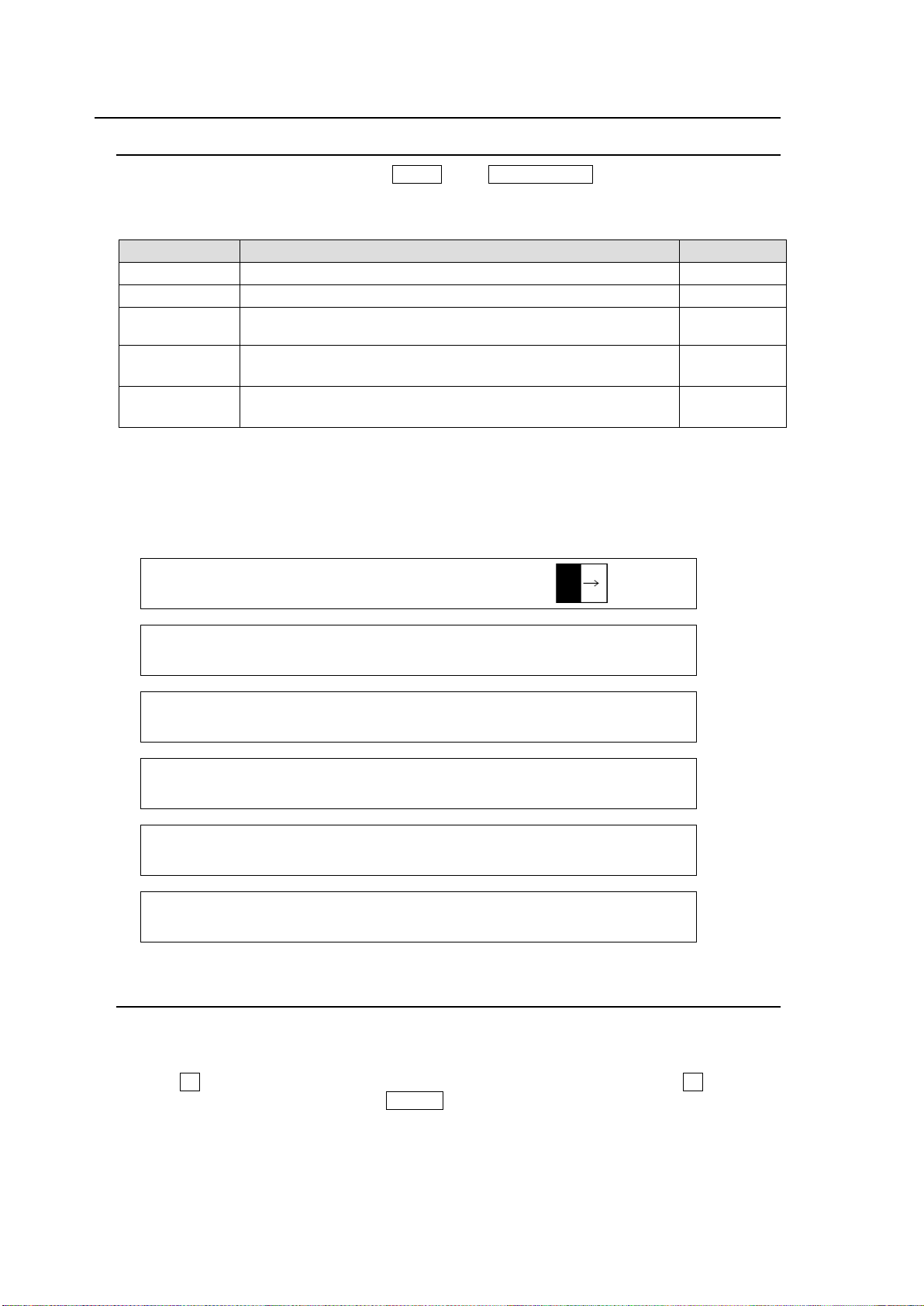
8-11. Transition Settings
Parameter
Description
Refer to sec.
RATE
Sets the transition rate for each bus.
8-11-2
TRANS LINIT
Sets the transition limit for each bus.
8-11-3
ADV CTL
Sets the transition function for the KEY1, KEY2, DSK1 and
DSK2 transition buttons (to the right side of the fader)
8-10-1
PAT NO
(PAGE 1)
Selects a pattern for the BKGD, KEY1 and KEY2 pattern
transitions.
8-8-1
ENABLE
(PAGE 6)
Enables/Disables the BLACK TRANSITION button.
8-7
TRANS : RATE :TRANS LIMIT :PAT NO : 1/6
BKGD : =30 :=100.0 =OFF : =0 :
TRANS : RATE :ADV CTL: TRANS LIMIT : 2/6
KEY1 : =30 : =AUTO : =100.0En=OFF :
TRANS : RATE :ADV CTL: TRANS LIMIT : 3/6
KEY2 : =30 : =AUTO : =100.0En=OFF :
TRANS : RATE :ADV CTL: TRANS LIMIT : 4/6
DSK1 : =30 : =AUTO : =100.0En=OFF :
TRANS : RATE :ADV CTL: TRANS LIMIT : 5/6
DSK2 : =30 : =AUTO : =100.0En=OFF :
TRANS : RATE :ENABLE : : 6/6
BLACK : =30 : =ON : :
8-11-1. TRANS Menu
To display the [TRANS] menu, press MENU, then TRANS RATE in the SELECT/KEYPAD
block. The [TRANS] menu consists of six pages for each bus. Use the page down or up
button to move between pages.
Pressing the following buttons in the transition block can also open the related TRANS menu
page.
BKGD, KEY1, KEY2 (NEXT TRANSITION butons on the left side of the fader)
MIX, WIPE (TRANSITION TYPE buttons)
8-11-2. Transition Rate
The transition rate setting determines how long the transition takes in frames to complete.
(1) Open the desired [TRANS] menu page.
(2) Turn F1 to set the transition rate. To enter the rate in the KEYPAD, press F1, enter the
rate using the keypad, then press ENTER in the keypad to store the new transition rate.
The setting range is 0 to 999 on a frame basis.
78
Page 79
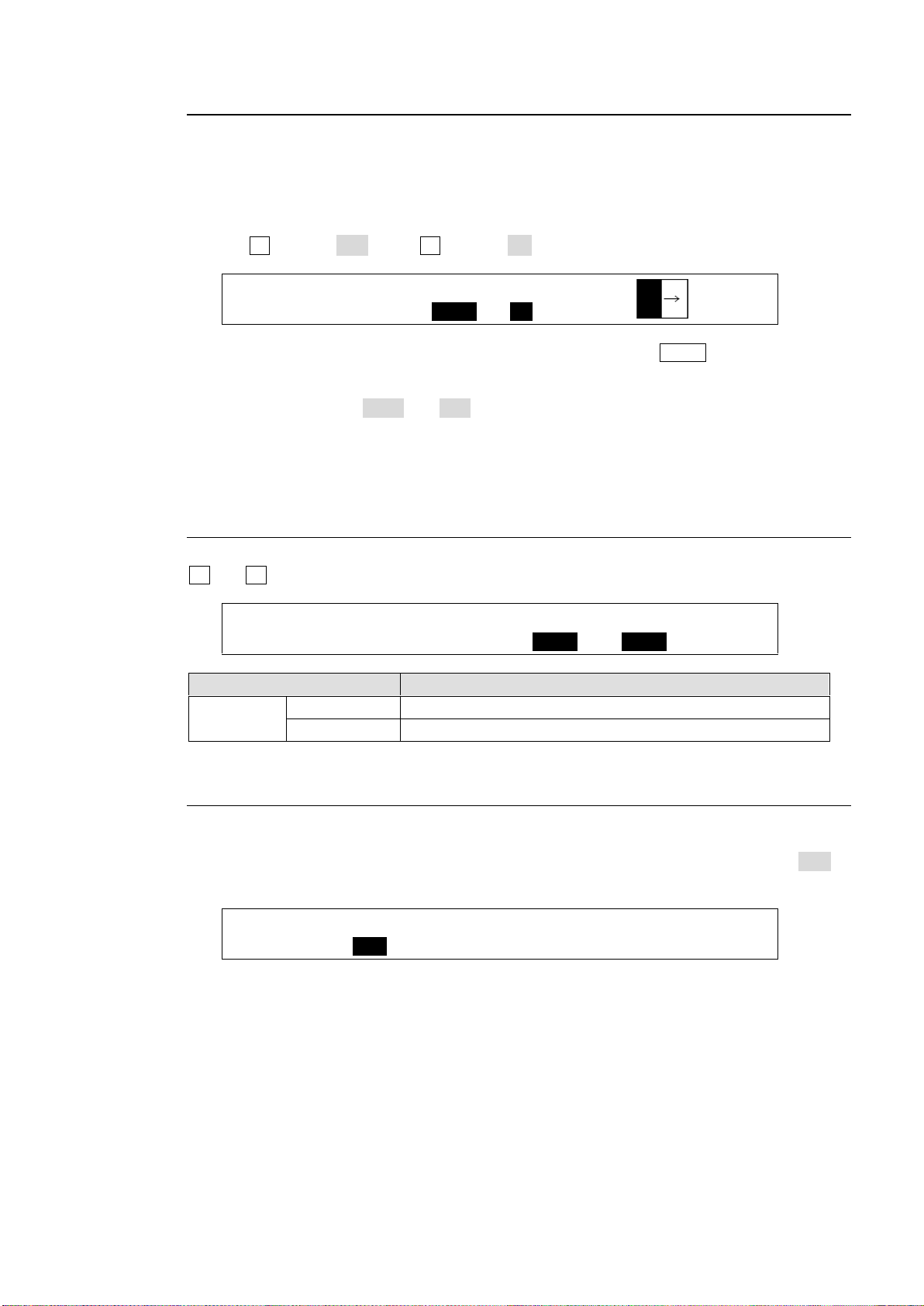
8-11-3. Transition Limit
TRANS : RATE :TRANS LIMIT :PAT NO : 1/6
BKGD : =30 :=90.0 =ON : =0 :
PANEL :BUSTYPE: : FADER OFFSET : 1/1
M/E CTRL: =P/P : :U=1.00 L=1.00 :
Parameter
Description
FADER
OFFSET
U
Sets the upper edge offset.
L
Sets the bottom edge offset.
FUNCTION:TRSEDGE:KEY LNK: DSK ASSIGN : 1/1
M/E KEY : =OFF : =ON :1=M/E 2=M/E :
The Transition Limit setting determines how far your transition can proceed. When
performing transitions (mix or other) there may be times when you want the transition to the
next signal to only complete to a certain degree instead of fully switching from one picture to
another.
To perform background transitions that do not fully switch pictures, proceed as follows.
(2) Turn F2 to set to 90.0. Turn F3 to set to ON under TRANS LIMIT.
(3) Let's perform background MIX or WIPE transitions by pressing AUTO or moving the fader
lever. The transition must be completed before the background pictures are fully switched.
The default settings are 100.0 and OFF. With this setting, the transition is complete with fully
switching pictures.
In the following menu pages, the transition limit for KEY1-2 and DSK1-2 can be set in the
same way
8-11-4. Adjusting the Fader Offset
The fader offset range can also be adjusted in the [SETUP - PANEL - TRS CTRL] menu. Turn
F3 and F4 to adjust the fader OFFSET.
8-11-5. Endpoint Processing for DVE Transitions
In DVE operations, differences in video delay times when entering and exiting DVE effects
can cause the video to appear choppy. This choppiness can be reduced by menu setting so
that the DVE effect always exits at the transition start and end points (TRS EDGE to OFF in
the [SETUP - FUNCTION - M/E_KEY] menu).
79
Page 80
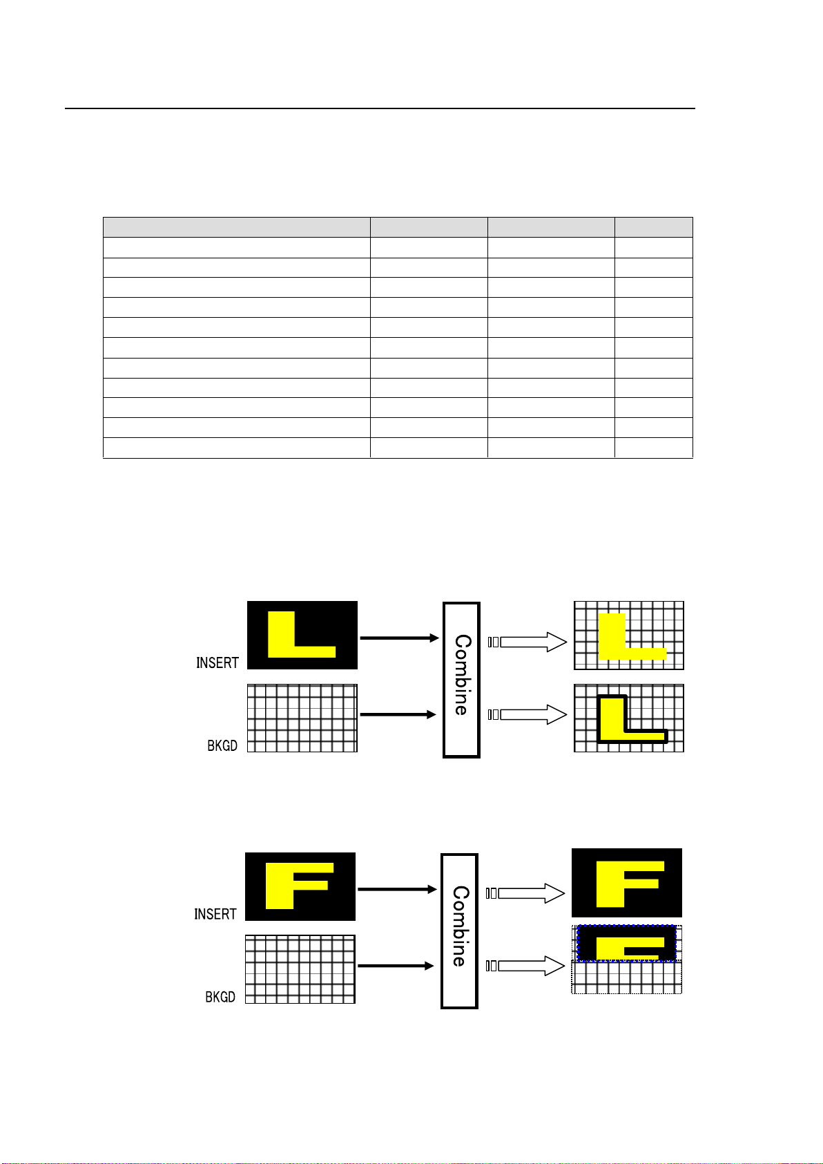
9. KEY/DSK
Feature
KEY1 and KEY2
KEY3 and KEY4
Refer to
Luminance key
Available
Available
9-1
Full key
Available
Available
9-2
Bus key
Available
Available
9-3
Key invert
Available
Available
9-6-1
Box mask, signal mask
Available
Available
9-6-2
Preset mask
Available
-
9-6-2
Edge effect
Available
-
9-7
Pattern transition
Available
-
8-8
2D DVE
Available
Available
9-8
IN/OUT effects
Available
Available
8-10
AUX output
-
Available
8-5-1
Luminance Key
Edge
Full Key
BOX(AND)
mask
The key feature enables you to superimpose titles and images onto background signals. With the
switcher, four key channels are provided: KEY1-2 and DSK1-2. Three key types are available in all
keyers: Luminance Key, Full Key and Bus Key. Key Invert, Mask and 2D DVE effects can also be
added to keys. Furthermore, Edge effects can be used in KEY1 and KEY2.
KEY1, KEY2, DSK1 and DSK2 Features
The following section describes key setup and adjustment using KEY1 as an example.
Luminance Key
Luminance Key, also called Self Key, uses the same image for Key Source and Key Insert. This
image is selected from Key Insert.
Full Key
Full Key displays the key insert signal full-screen.
80
Page 81
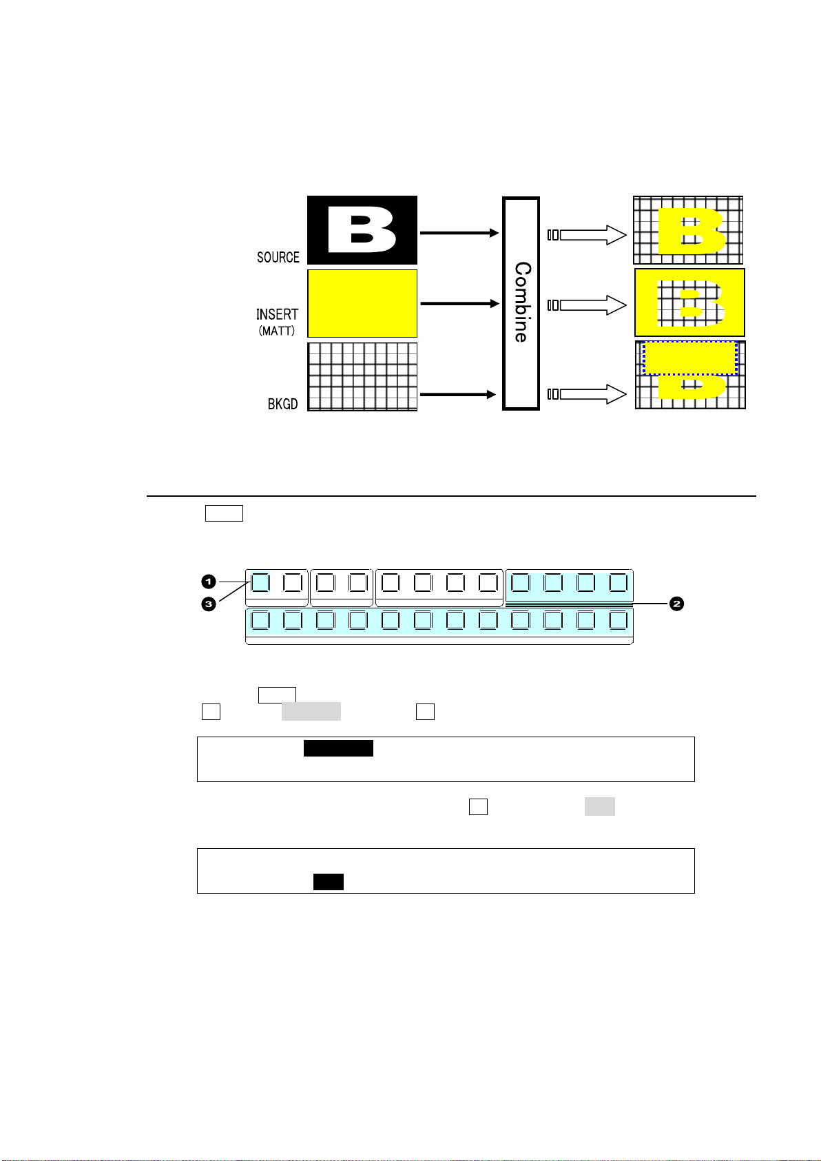
Bus Key
KEY1 :>INS/SRC >EDGE >MASK
SETUP :>POS/SIZ >BORDER >INIT
KEY1 : TYPE :INSERT :SOURCE :INVERT : 1/4
INS/SRC : =LUM : =IN01 : =IN01 : =OFF :
Bus key
BOX(OR)
mask
INVERT
1 1 1
1
2 2 2 3 4
2 3 4 5 6 7 8 9 10 11 12
KEYER DSK AUX
KEY/AUX
PGM PREV CLEAN MV
Bus Key, also called External Key, uses different images for Key Source and Key Insert. The
background signal is cut out using Key Source and Key Insert fills in the cut-out part of the
signal.
9-1. Luminance Key
(1) PressKEY1 above the KEY/AUX bus.
(2) Select a signal for Key Insert in the KEY/AUX bus.
(3) Double-press KEY1 above the KEY/AUX bus to display the [KEY1 SETUP] menu.
(4) Turn F1 to select INS/SRC, and press F1 or the page down button.
(5) The [KEY1 - INS/SRC] menu is displayed. Turn F1 to set TYPE to LUM. The insert signal can
also be selected at INSERT.
See section 8-4. "KEY Transitions" and 8-10. "KEY/DSK IN/OUT Effects" for details on
transitions.
See section 9-4. "Adjusting Key Signal" for details on making fine adjustments. Edge (KEY1
and 2 only), Invert, Mask and 2D DVE effects can be applied to Luminance keys.
81
Page 82
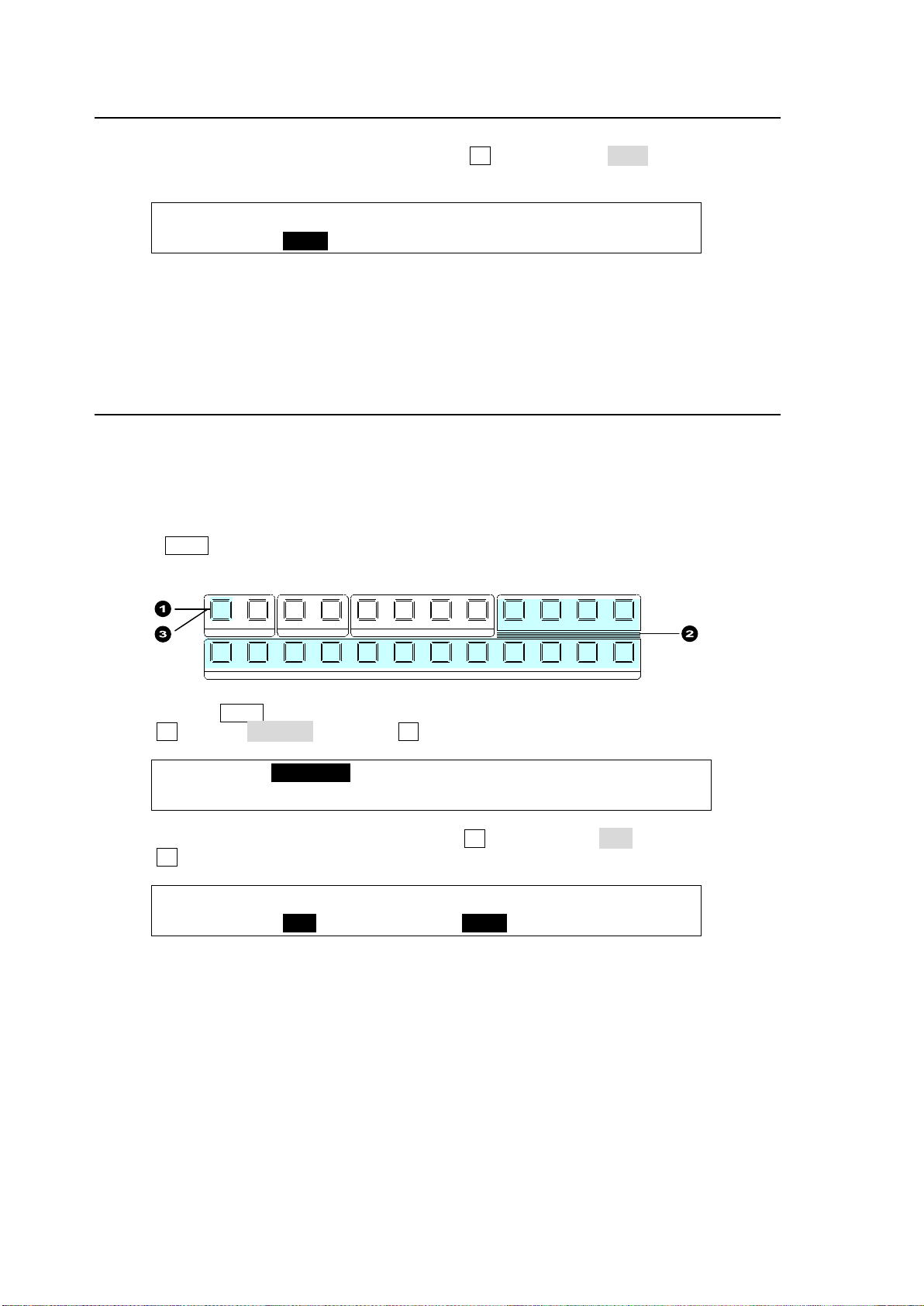
9-2. Full Key
KEY1 : TYPE :INSERT :SOURCE :INVERT : 1/4
INS/SRC : =FULL : =IN01 : =IN01 : =OFF :
KEY1 :>INS/SRC >EDGE >MASK
SETUP :>POS/SIZ >BORDER >INIT
KEY1 : TYPE :INSERT :SOURCE :INVERT : 1/4
INS/SRC : =BUS : =IN01 : =IN02 : =OFF :
1 1 1
1
2 2 2 3 4
2 3 4 5 6 7 8 9 10 11 12
KEYER DSK AUX
KEY/AUX
PGM PREV CLEAN MV
(1) Follow Step (1) to (4) in "Luminance Key" above.
(2) The [KEY1 - INS/SRC] menu is displayed. Turn F1 to set TYPE to FULL. The insert signal
can also be selected at INSERT.
See section 8-4. "KEY Transitions" and 8-10. "KEY/DSK IN/OUT Effects" for details on
transitions.
See section 9-4. "Adjusting Key Signal" for details on making fine adjustments. Edge (KEY1
and 2 only), Invert, Mask and 2D DVE effects can be applied to Luminance keys.
9-3. Bus Key
Bus Key uses different signals for Key Insert and Key Source. To create a Bus Key, select a Key
Insert signal and a Key Source signal in the menus. Since selecting a signal in the menu takes
time, the switcher has a KEY LINK function, which enables you to select a key source and insert
using only a source button.
See section 9-3-1. "Key Link" for details.
(1) Press KEY1 above the KEY/AUX bus.
(2) Select a signal for Key Insert in the KEY/AUX bus.
(3) Double-press KEY1 above the KEY/AUX bus to display the [KEY1 SETUP] menu.
(4) Turn F1 to select INS/SRC, and press F1 or the page down button.
(5) The [KEY1 - INS/SRC] menu is displayed. Turn F1 to set TYPE to BUS.
(6) Turn F3 to select a signal for Key Source in SOURCE.
See section 8-4. "KEY Transitions" and 8-10. "KEY/DSK IN/OUT Effects" for details on
transitions.
See section 9-4. "Adjusting Key Signal" for details on making fine adjustments. Edge (KEY1
and 2 only), Invert, Mask and 2D DVE effects can be applied to Luminance keys.
82
Page 83
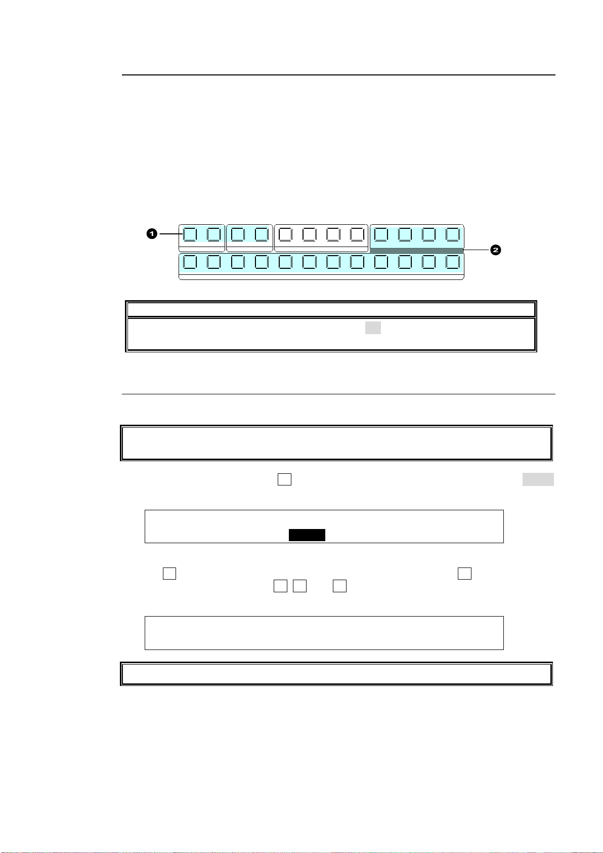
9-3-1. Key Link
NOTE
If key links do not work properly, set LINK to ON in the [SETUP- FUNCTION M/E_KEY] menu.
KEY INSERT MATT is a dedicated matte signal for keys and it is not the same as BUS
MATT. The different colors can be set in KEY INSERT MATT for each key.
KEY1 : TYPE :INSERT :SOURCE :INVERT : 1/4
INS/SRC : =BUS : >InMAT: =IN02 : =OFF :
KEY1 : MATT COLOR :RECALL : 4/4
INS MATT:S=67.3 L=15.8 H=257.5: >RED :
Key Links cannot be applied to KEY MATT.
1 1 1
1
2 2 2 3 4
2 3 4 5 6 7 8 9 10 11 12
KEYER DSK AUX
KEY/AUX
PGM PREV CLEAN MV
A Key Source signal can be selected concurrently when a Key Insert signal is selected if KEY
LINK is on. The INSERT/SOURCE signal pairs for Bus keys are automatically set once they
are selected for a key. To change signal assignment, select the INSERT/SOURCE signal pair
again for the key or another key. The same assignments are shared among all keys of
KEY1-2 and DSK1-2.
When Using the Key Link:
(1) Select a key among KEY1-2 and DSK1-2.
(2) Select a signal for KEY INSERT in the KEY/AUX. This allows users to set a key signal
pair: KEY INSERT and KEY SOURCE signals.
9-3-2. KEY INSERT MATT
In addition to the bus matt signal, the internally generated MATT can be used as key fill.
(1) Set up a Bus Key, then press F2 in the [KEY1 - INS/SRC] menu to set INSERT to InMAT
(Insert Matt).
(2) Press the page down button to go to PAGE 4.
(3) Turn F4 and select a color among eight standard colors, then press F4.
To use a different color, turn F1, F2, and F3 to adjust the color.
See section 5-9-1. "Setting the Matte Color."
83
Page 84
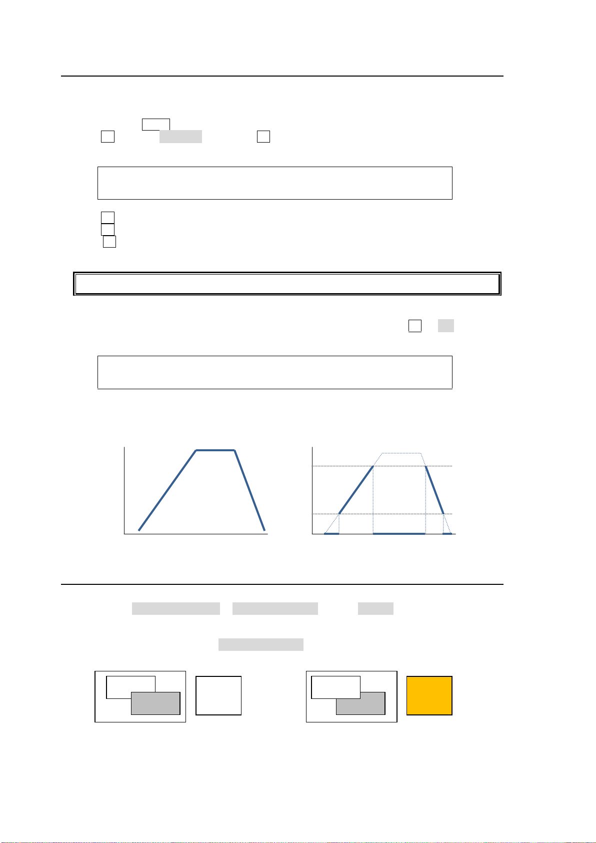
9-4. Adjusting the Key Signal
KEY1 : GAIN : CLIP :TRANSP :FAM : 2/4
ADJUST : =1.0 : =6.2 : =0.0 : =OFF :
Clip thresholds of key signals can be set for Bus and Luminance keys.
KEY1 :CLIP-H :CLIP-L :ENABLE : : 3/4
KEY CLIP: =100.0: =0.0 : =ON : :
100.0%
Pixel
0.0%
CLIP-H
CLIP-L
Key
luminance
level
100.0%
Pixel
0.0%
USER
button
lit orange
USER
button
lit white
KEY1
KEY2
KEY2
KEY1
Clip and Gain allows users to adjust the key signal and its composition over the background.
KEY transparency can also be adjusted.
(1) Double-press KEY1 above the KEY/AUX bus to display the [KEY1 SETUP] menu.
(2) Turn F1 to select INS/SRC, and press F1 or the page down button.
(3) The [KEY1 - INS/SRC] menu is displayed. Press the page down button to go to PAGE2.
(4) Turn F1 to adjust GAIN
(5) Turn F2 to adjust CLIP for adjusting the key.
(6) Turn F3 to set the level of key transparency. Increasing the value makes the key more
transparent.
(7) Go to PAGE 3.
(8) Set key luminance thresholds levels under CLIP-H and CLIP-L. Turn F3 to ON to enable
these limits.
Clip Example
Original Key signal Clipped Key signal
9-5. Changing KEY or DSK Layer Order
Layer order between KEY1 and KEY2, and DSK1 and DSK2 can be changed using a USER
button. Assign KEY1/2PRIORITY or DSK1/2PRIORITY (TYPE: KEYER) to a USER button.
See section 14. "USER Buttons."
Press the USER button, to which KEY1/2PRIORITY is assigned.
KEY1 appears in front of KEY2.
The DSK layer order can be changed in the same way as that of KEY order.
Also note that two DSK layers are always placed in front of two KEY layers.
84
Page 85
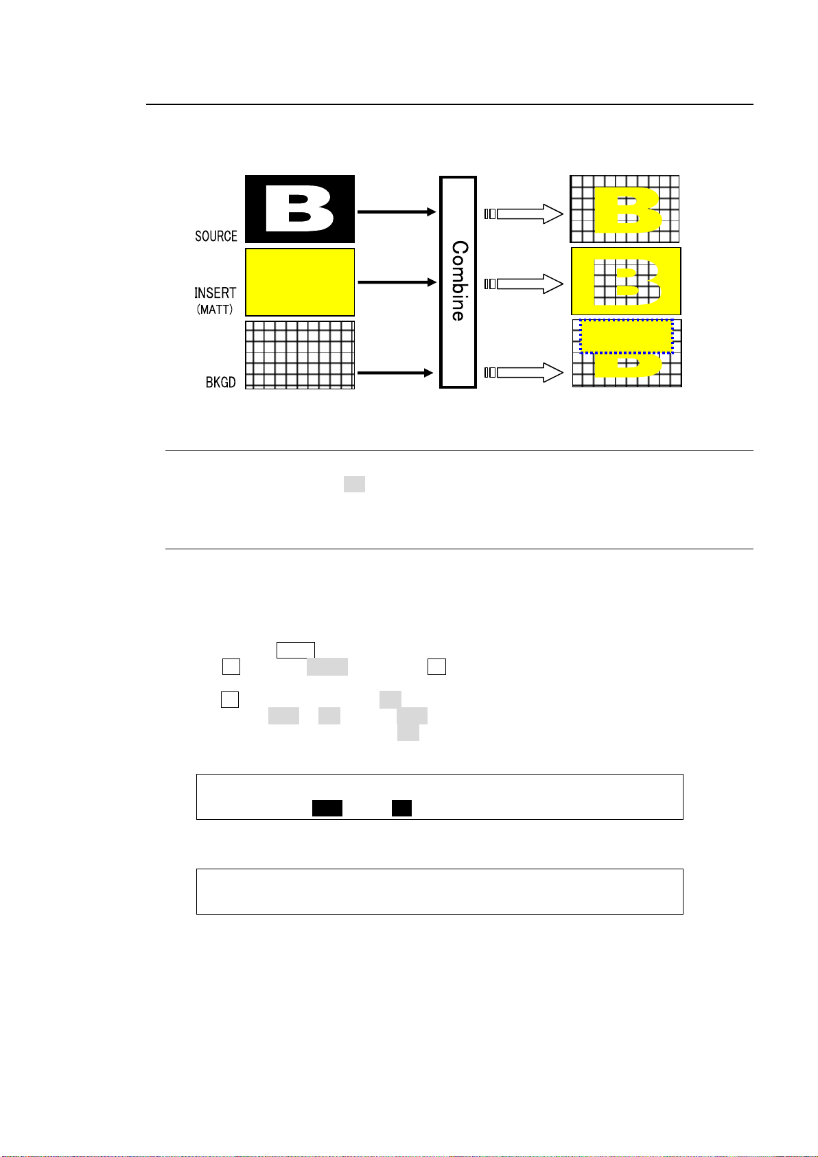
9-6. Mask and Invert
KEY1 : TYPE :BOX MSK:MASK(EXT/PST) : 1/5
MASK : =AND : =ON : S=OFF :INV=OFF:
KEY1 : BOX MASK POSITION : 2/5
MASK POS:T=0 B=0 L=0 R=0 :
Bus key
BOX(OR)
mask
INVERT
Mask and Invert can be used for all keys. Preset masks are available only for KEY1 and KEY2.
9-6-1. Inverting Key and Background
Setting Invert to ON inverts the key image and the background image. Set INVERT in the
[KEY1 - INS/SRC] menu to ON. The key signal is then inverted.
9-6-2. Key Masks
BOX Mask
Box-shaped masks can be applied to keys. They can also be inverted so that the keyed area
inside the box becomes invisible.
(1) Create KEY1.
(2) Double-press KEY1 above the KEY/AUX block to display the [KEY1 SETUP] menu.
(3) Turn F1 to select MASK, and press F1 or the page down button to open the [KEY1 -
MASK] menu.
(4) Turn F2 to set BOX MASK to ON in PAGE 1 of the [KEY1 - MASK] menu.
(5) Set TYPE to AND or OR. If set to AND, the area where Key Source and Box Mask overlap
is used as the key signal. If set to OR, both Key Source and Box Mask are used as the key
signal.
(6) Set the horizontal and vertical mask width on PAGE 2 in the MASK menu.
85
Page 86
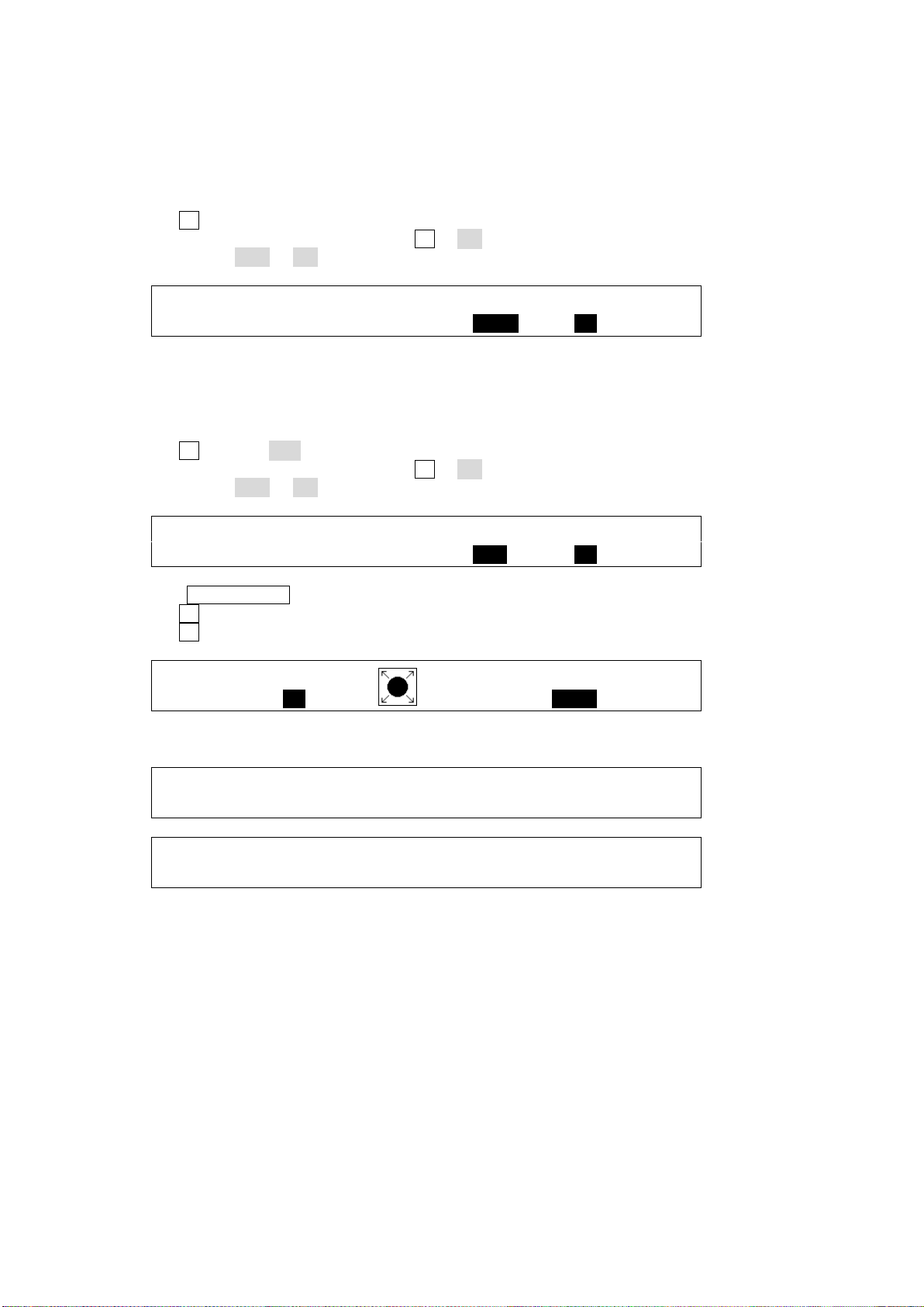
Signal Mask
KEY1 : TYPE :BOX MSK:MASK(EXT/PST) : 1/5
MASK : =AND : =OFF : S=AUX5:INV=ON :
KEY1 : TYPE :BOX MSK:MASK(EXT/PST) : 1/5
MASK : =AND : =OFF : S=PST :INV=ON :
KEY1 :PATTERN : :LEVEL : 3/5
WIP PTRN: =51 : : =50.0 :
KEY1 : POSITION : ANGLE :ASPECT : 4/5
WIP POS :X=0 Y=0 : =0.0 : =0.0 :
KEY1 : MULTI : SOFT : : 5/5
WIP MULT:X=1 Y=1 : =0.0 : :
Video inputs can be used for mask signals instead of Box. Inputs used for masks must be
assigned to AUX1 to AUX8. Combined video signals such as program or multi-view cannot
be used.
(1) Open [KEY1 - MASK] menu PAGE 1. (See the previous page.)
(2) Turn F3 to select a mask signal.
(3) If you want to invert a key signal, turn F4 to ON.
(4) Set TYPE to AND or OR.
Preset Mask
WIPE patterns can be used for mask signals for KEY1 and KEY2.
(1) Open the [KEY1 - MASK] menu PAGE 1. (See the previous page.)
(2) Turn F3 to select PST (PRESET).
(3) If you want to invert a key signal, turn F4 to ON.
(4) Set TYPE to AND or OR.
(5) Press PAGE DOWN to go to PAGE 3.
(6) Turn F1 to select a wipe pattern.
(7) Turn F4 to change the pattern shape.
(8) Mask patterns can be modified referring to PAGE 4 and 5
86
Page 87
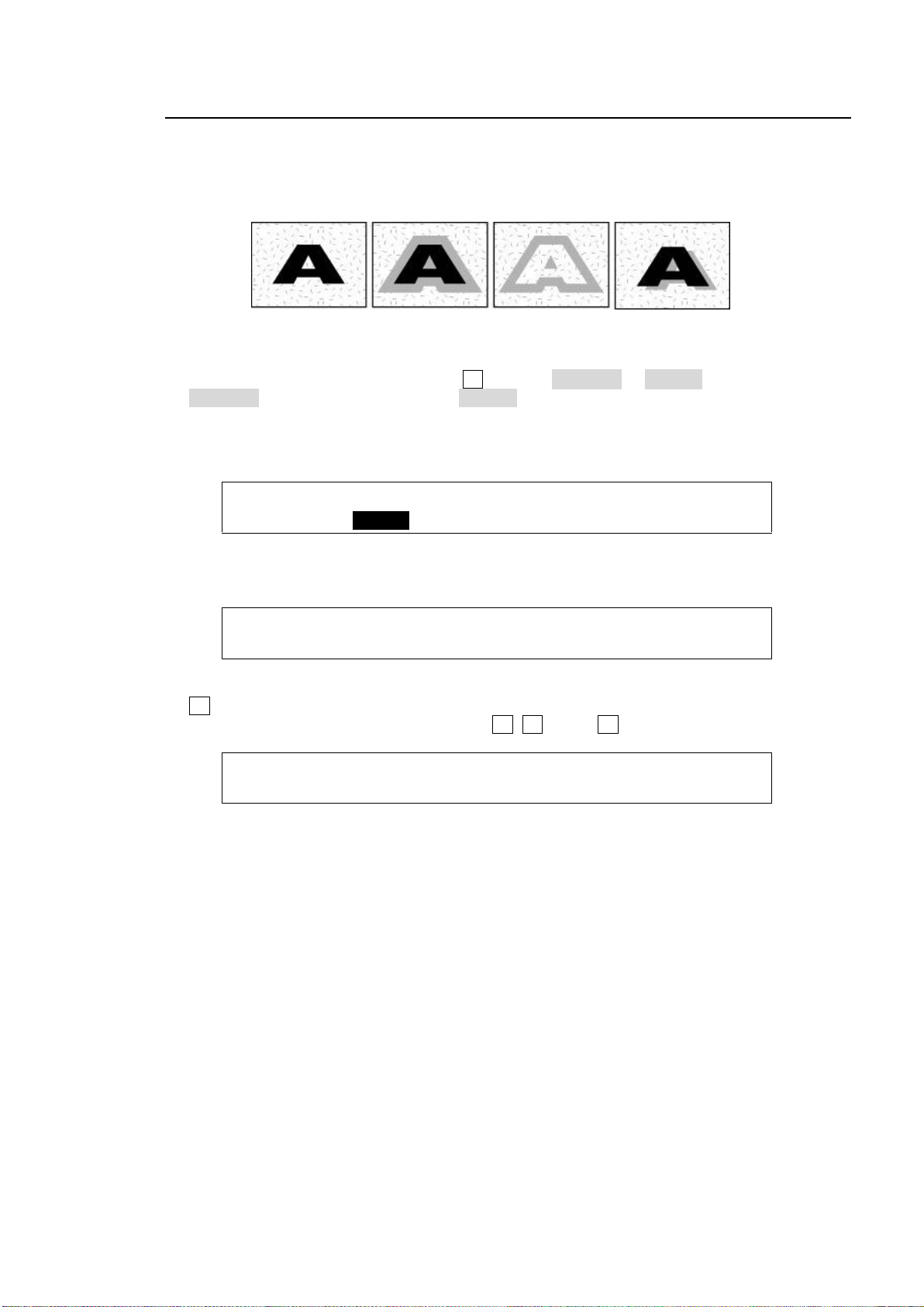
9-7. Key Edge
KEY1 : TYPE : SOFT :TRANSP : WIDTH : 1/3
EDGE : =O_LIN: =0 : =0 : =1 :
KEY1 : POSITION : : 2/3
EDGE POS:X=0 Y=0 : :
KEY1 : EDGE COLOR :RECALL : 3/3
EDGE COL:S=0.0 L=0.0 H=0.0 : >BLACK:
No edge, no shadow
Normal edge
Outline edge
Shadow
The EDGE function allows users to add border type edges on KEY1 and KEY2. Two types of
edges are available: Normal and Outline. The width, transparency, and color can be set for the
edges. Shadow effects can also be added by changing the position of edges. This chapter
shows how to add a key edge using KEY1 as an example.
(1) Go to the [KEY1 - EDGE] menu. Turn F1 to select NORMAL or O_LINE for TYPE. Selecting
NORMAL allows users to add edges. O_LINE allows users to display outlines without key fill
images.
(2) The SOFT parameter is for setting softness, TRANSP is for transparency, and WIDTH is for
edge width.
(3) Press the page down button to go to PAGE2. Change the X and Y values to set the edge
position.
(4) Press the page down button to go to PAGE3. The edge color can be set on this page. Turn
F4 to select a color among eight standard colors. If you wish to use a color other than the
standard eight, adjust the color by turning F1, F2 and/or F3.
87
Page 88
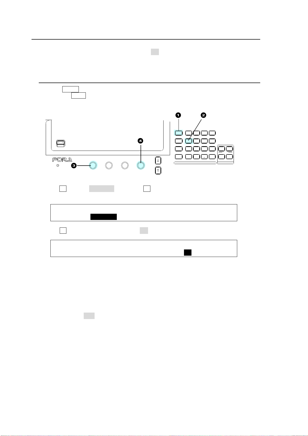
9-8. DVE Effects on KEY/DSK
KEY1 :>INS/SRC >EDGE >MASK
SETUP :>POS/SIZ >BORDER >INIT
KEY1 : POSITION : SIZE :2D DVE : 1/5
POS/SIZE:X=0 Y=0 : =1000 : =ON :
USB MEMORY
DIGITA L VIDEO SWITCHER
ALARM
F1 F2 F3 F4
PAGE
MENU ATTACH
DIRECT
PATT
DETACH
SETUP
KEY1
POSITION
POS ROT
2D DVE
WIPE
POS
MENU
JOYSTICK
8 9
4 5 6
STILL MATT FILE
KEY2 DSK1 DSK2
EVENT
MACRO
1 2 3
0
CLEAR
RECALL STORE
ENTER
CK EFFECT
TRANS RATE WIPE
SELECT/KEYPAD
±
7
Dedicated 2D-DVE(2.5D) effects are available for each key in the standard configuration.
2D-DVE is available just by setting 2D DVE to ON in each key menu. As an example, this
section explains how to add a 2D-DVE effect on KEY1.
9-8-1. How to Enable 2D DVEs
(1) Press MENU in the SELECT/KEYPAD block.
(2) Press the KEY1 button to display the [KEY1 SETUP] menu.
(3) Turn F1 to select POS/SIZE, then press F1 or the page down button to display the [KEY1
- POS/SIZE] menu
(4) Turn F4 to set 2D DVE in the menu to ON.
The 2D DVE function is enabled for KEY1, and therefore the POS/SIZE and BORDER
menus for KEY1 become available.
If 2D DVE cannot be set to ON:
Up to 4 channels of DVE can be assigned to BKGD, KEY1-2 and DSK1-2. If no free DVE
channels remain, 2D DVE cannot be enabled. In such case, deselect the assigned DVE
channels as shown below to create free channels.
Set 2D DVE to OFF (for KEY and DSK)
See section 9-8-1. "How to Enable 2D DVEs."
Change transitions from WIPE (pattern: 100-137) to MIX (for KEY and BKGD):
See section 8-3. "Background Transitions" and section 8-4. "KEY Transitions."
88
Page 89
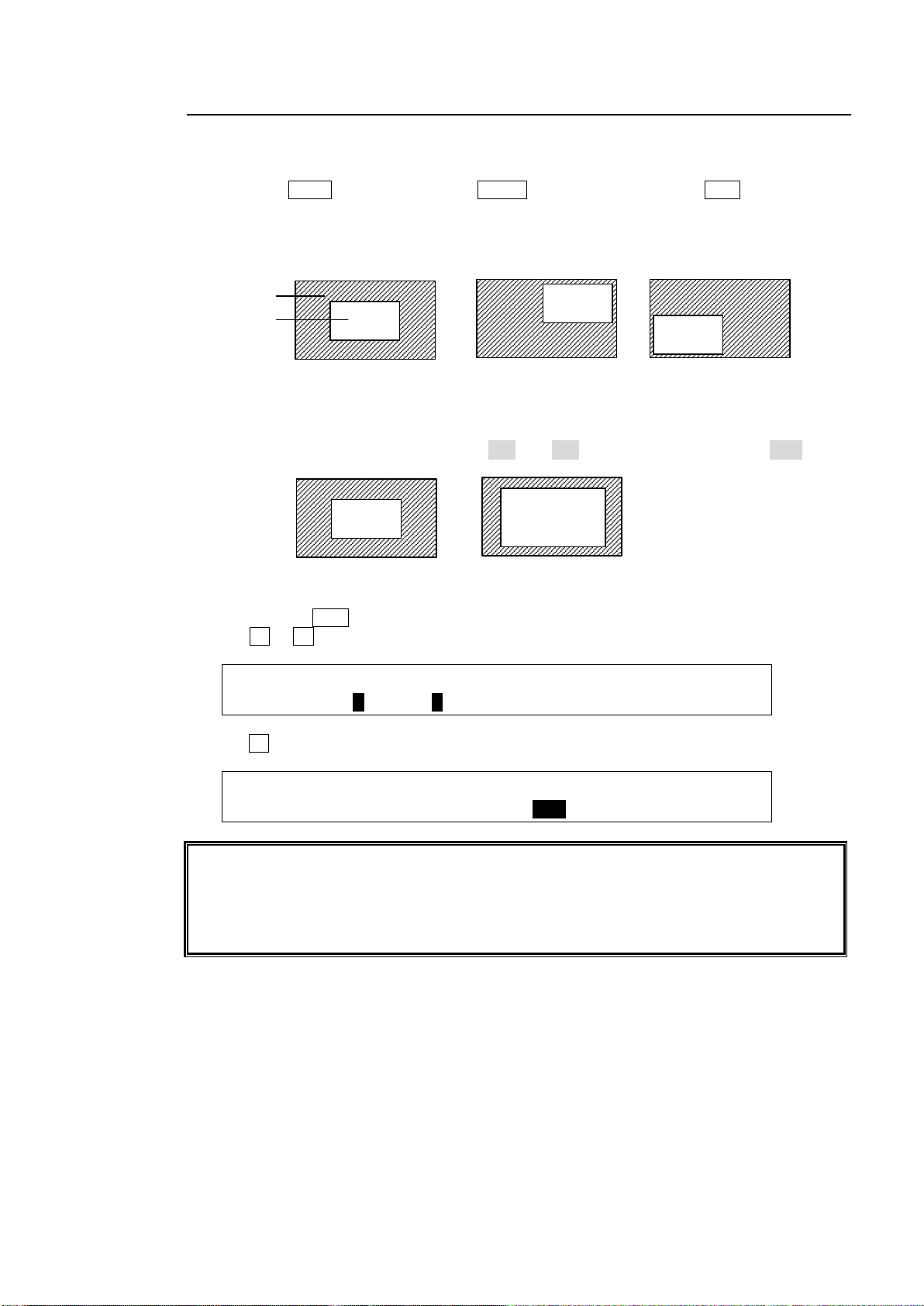
9-8-2. Changing Position and Size
KEY1 : POSITION : SIZE :2D DVE : 1/5
POS/SIZE:X=0 Y=0 : =500 : =ON :
KEY1 : POSITION : SIZE :2D DVE : 1/5
POS/SIZE:X=0 Y=0 : =500 : =ON :
The original base POSITION of a key is at the center of the output screen. You can set the
position of the key images by specifying X and Y coordinates, with the origin of the axes
located at the center of the screen.
Setting the size allows users to change the size of key images while retaining aspect ratios.
If the value is 1,000, the key images will be full-screen size.
POSITION(0,0)
POSITION(200,200)
POSITION(-200,-200)
Background
KEY1 image
SIZE(500)
SIZE(750)
The position and size of key images can be changed using the menu or joystick as follows:
Using the Joystick:
(1) Press the KEY1 menu button (with MENU lit) while holding down POS in the joystick
block.
(2) Change the KEY1 position by moving the joystick up, down, left and right.
Change the key size by turning the SIZE control in the joystick block.
The figures below are examples of SIZE=500 and 750 when POSITION is set to (0, 0).)
Using the Menu
(1) Double-press POS in the joystick block to display [KEY1 - POS/SIZE] menu PAGE1.
(2) Turn F1 or F2 to set the position of the KEY1 image.
(3) Turn F3 to set the size of the KEY1 image.
89
Page 90
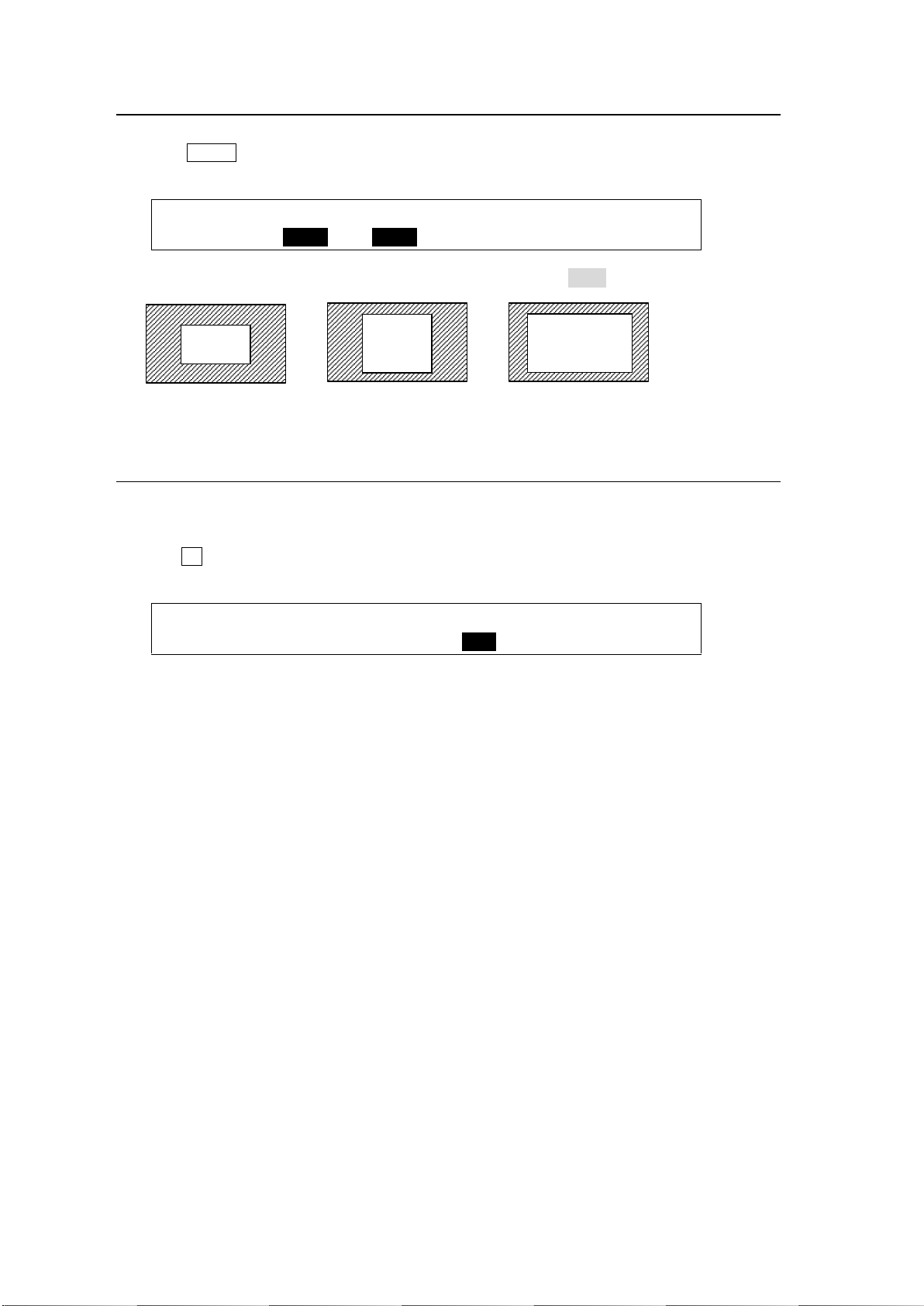
9-8-3. Changing the Aspect Ratio
KEY1 : ASPECT :FADE LV: : 2/5
ASPECT :X=1000 Y=1000 : =0.0 : :
KEY1 : ASPECT :FADE LV: : 2/5
ASPECT :X=1000 Y=1000 : =0.0 : :
(500, 500)
(500, 750)
(750, 750)
(1) Go to the [KEY1 - POS/SIZE] menu PAGE 2.
(2) Press MENU in the joystick block.
(3) Change the KEY1 ASPECT values by moving the joystick up, down, left and right.
(The figures below are examples when POSITION is set to (0, 0).)
9-8-4. FADE
FADE allows users to add an effect to make backgrounds transparent.
(1) Go to the [KEY1 - POS/SIZE] menu PAGE 2.
(2) Turn F3 to set the FADE level for the KEY1 image. Increasing the value makes the
background transparent.
90
Page 91
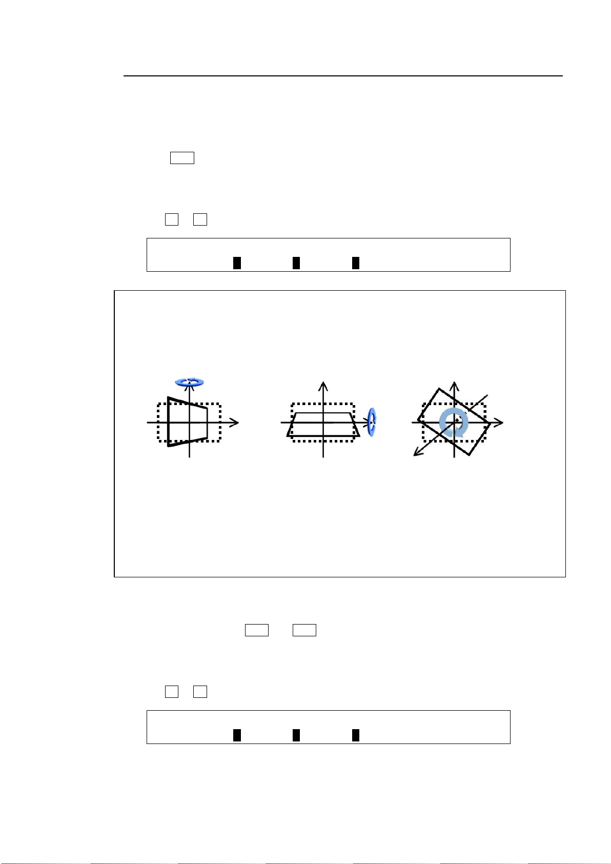
9-8-5. Rotation
KEY1 : LOCAL ROTATION : : 3/5
ROTATION:X=0 Y=0 Z=0 : :
KEY1 : CENTER POSITION : : 4/5
ROTATION:X=0 Y=0 Z=0 : :
X-Rotation
LOCAL ROTATION
(100,0,0)
Y-Rotation
LOCAL ROTATION
(0,100,0)
Z-Rotation
LOCAL ROTATION
(0,0,100)
In addition to positional and size changes, users can add a rotation effect to key images.
Specifying the Rotation Angle (Number of Rotation)
Using the Joystick
(1) Press ROT for 2D DVE in the joystick block.
(2) Move the joystick (X/Y-axes) and SIZE control (Z-axis) to change the rotation angles.
Using the Menu
(1) Go to PAGE 3 of the [KEY1 - POS/SIZE] menu.
(2) Turn F1 to F3 to change rotation angles in the X, Y and Z directions.
The LOCAL ROTATION values allow the key image around the base point to rotate up to
approximately eight times in the positive or negative direction.
X-Rotation: Rotates around the Y-axis.
Y-Rotation: Rotates around the X-axis.
Z-Rotation: Rotates around the origin.
In the factory default setting, the base point coordinates (0,0,0) coincide with the center point
of the key image. The figure examples above show them rotating around the base point (0, 0,
0). Changing the CENTER POSITION values in the menu allows the base point to move.
Moving the Center of Rotation
Using the Joystick
(1) Simultaneously press POS and ROT for 2D DVE in the joystick block to turn them on.
(2) Move the joystick (X/Y-axes) and SIZE control (Z-axis) to move the center of rotation.
Using the Menu
(1) Go to PAGE 4 of the [KEY1 - POS/SIZE] menu.
(2) Turn F1 to F3 to move the center of rotation.
91
Page 92
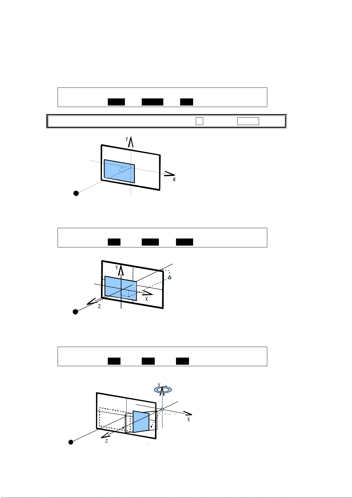
Setting Example
KEY1 : POSITION : SIZE :2D DVE : 1/5
POS/SIZE:X=-200 Y=-200 : =500 : =ON :
To enter a negative number, enter the number, press ± , then press ENTER.
KEY1 : CENTER POSITION : : 4/5
ROTATION:X=150 Y=-200 Z=-400 : :
KEY1 : LOCAL ROTATION : : 3/5
ROTATION:X=100 Y=100 Z=100 : :
POSITION(-200,-200)
SIZE 500
Point of view
Screen surface
POSITION(-200,-200)
SIZE 500
CENTER POSITION (150,-200,-400)
Center of rotation
Point of view
Screen surface
POSITION (-200,-200)
SIZE 500
CENTER POSITION (150,-200,-400)
ROTATION (100,0,0)
Point of view
Screen surface
Center of
rotation
(1) Set the key position and size on PAGE 1 of the [KEY1 - POS/SIZE] menu. Note that the
position is two-dimensional and its origin is placed on (0, 0), which coincides with the
center of the screen. The position values represent the distance between the origin and
the center of the KEY1 images. These values will be positive if the center of the key image
is above the origin and negative if it is below the origin.
(2)Change the center of rotation on PAGE4 of the [KEY1 - POS/SIZE] menu. To rotate the
key image at the current POSITION, leave CENTER POSITION (0, 0, 0) unchanged.
(3) Set the rotation value on PAGE3 of the [KEY1 - POS/SIZE] menu.
[Example 1] X-axis Rotation
92
Page 93
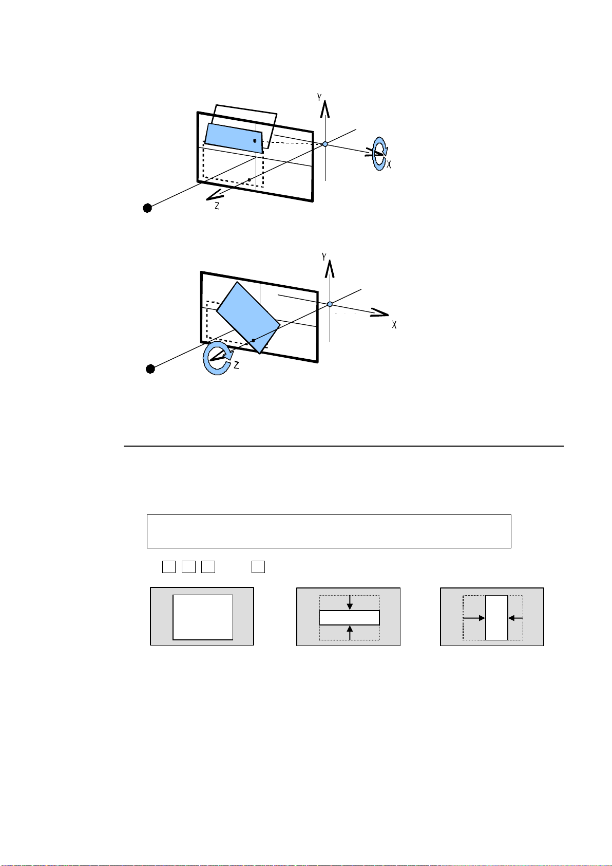
KEY1 : CROP POSITION : 5/5
CROP :T=0 B=0 L=0 R=0 :
POSITION (-200,-200)
SIZE 500
CENTER POSITION (150,-200,-400)
LOCAL ROTATION (0,0,100)
Point of view
Screen surface
Center of
rotation
Key image
Crops from top and bottom.
Crops from right and left.
POSITION (-200,-200)
SIZE 500
CENTER POSITION (150,-200,-400)
ROTATION (0,0,100)
Point of view
Screen surface
Center of
rotation
[Example 2] Y-axis Rotation
[Example 3] Z-axis Rotation
9-8-6. CROP
CROP allows users to trim a key image from all four directions. The background image then
only remains visible in the cropped area.
(1) Go to PAGE5 of the [KEY1 - POS/SIZE] menu.
(2) Use F1, F2, F3 and/or F4 to crop the KEY1 image.
93
Page 94
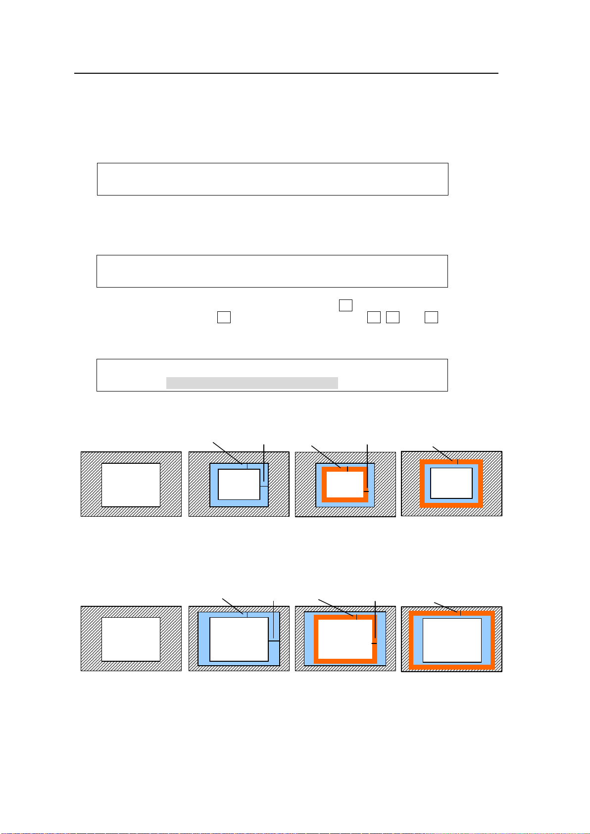
9-8-7. BORDERS
KEY1 : INSIDE : OUTSIDE : 1/3
BORDER :X=0 Y=0 :X=0 Y=0 :
KEY1 : INSIDE :OUTSIDE: : 2/3
BDR SOFT:X=0 Y=0 : =0 : :
KEY1 : BORDER COLOR :RECALL : 3/3
BDR COL :S=66.3 L=5.4 H=3.5 : >BLUE :
W/ border
Inner half
softness
SOFT-Y
SOFT-X
Key image
W/ border
Outer half
softness
EDGE SOFT
Key image
W/o border
Key image
W/ border
Y
X
Key image
W/o border
Key image
Key image
W/ border
Inner half
softness
SOFT-Y
SOFT-X
Key image
W/ border
Y
X
Key image
W/ border
Outer half
softness
EDGE SOFT
Borders can be added to key images. Inside borders and outside borders can be adjusted
independently.
(1) Go to the [KEY1 - BORDER] menu.
(2) To use the inside border, set the width on the INSIDE X and Y. To use the outside border,
set the width on the OUTSIDE X and Y.
(3) Press the page down button to go to PAGE2. In this menu, border softness can be
adjusted. INSIDE X and Y allow users to set softness for the inner half of a set border. The
softness of the outer half of the border is set at OUTSIDE.
(4) Press the page down button to go to PAGE3. Turn F4 to select a color among eight
standard colors, then press F4 . To use a different color, turn F1, F2, and F3 to adjust the
color.
See section 5-9-1. "Setting the Matte Color."
Inside Border
Outside Border
94
Page 95
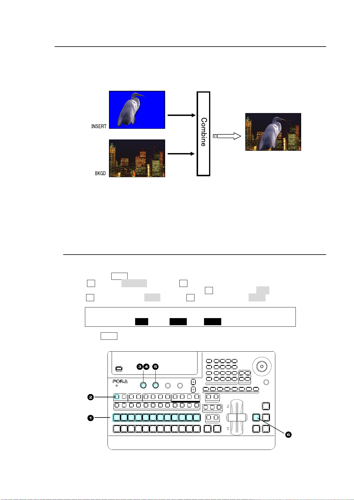
10. Chromakey
KEY1 : TYPE :INSERT :SOURCE :INVERT : 1/4
INS/SRC : =BUS : >CKFL : =CKKY : =OFF :
Chromakey
USB MEMORY
DIGITAL VIDEO SWITCHER HVS-
XT
SIZE
(PUSH to DEF)
1 2 3 4 5 6 7 8
USER BUTTON
REV NOR/REV
DIRECTION
BLACK
TRANS
BKGD KEY1 KEY2
NEXT TRANSITION
MIX WIPE
KEY1 KEY2
TRANSITION TYPE
AUTO CUT DSK1 D SK2
ALARM
F1 F2 F3 F4
PAGE
1 1 1
1
2 2 2 3 4
2 3 4 5 6 7 8 9 10 11 12
KEYER DSK AUX
KEY/AUX
PGM PREV CLEAN MV
PGM
PST
1 2 3 4 5 6 7 8 9 10 11 12
MENU AT TA CH
DIRECT
PATT
DETACH
SETUP
KEY1
POSITION
POS R OT
2D DVE
WIPE
POS
MENU
JOYSTICK
8 9
4 5 6
STILL MATT FILE
KEY2 DSK1 DSK2
EVENT
MACRO
1 2 3
0
CLEAR
RECALL STORE
ENTER
CK EFFECT
TRANS RATE WIPE
SELECT/KEYPAD
±
7
The chromakey method of key signal creation, which uses a chroma component instead of a
luminance component, is mostly used to composite moving subjects such as a person inside a
virtual background environment. For example, to place a person over a virtual background, first film
the person standing in front of a background such as a blue screen. The blue part of the filmed
image is detected and will be used to create the key signal.
The switcher has a single chromakey generator, which generates chromakey Fill and Key
signals by specifying a video signal and chromakey color. The Fill and Key signals can be output
respectively from AUX outputs, and assigned to any KEY or DSK on the switcher to display the
output onto the background video.
This chapter explains how to create and combine a chromakey with background video and adjust
the appearance using KEY1 as an example .
10-1. Creating a Chromakey
Setting Up KEY1
(1) Select a signal to be used as a background on the PGM bus.
(2) Double-press KEY1 above the KEY/AUX block to display the [KEY1 SETUP] menu
(3) Turn F1 to select INS/SRC, and press F1 or the page down button.
(4) The [KEY1 - INS/SRC] menu is displayed. Turn F1 to set TYPE to BUS.
(5)Turn F2 to set INSERT to CKFL and turn F3 to set SOURCE to CKKY.
(6) Press the KEY1 transition button in the bottom right of the control panel to display KEY1 on
the PGM image.
95
Page 96
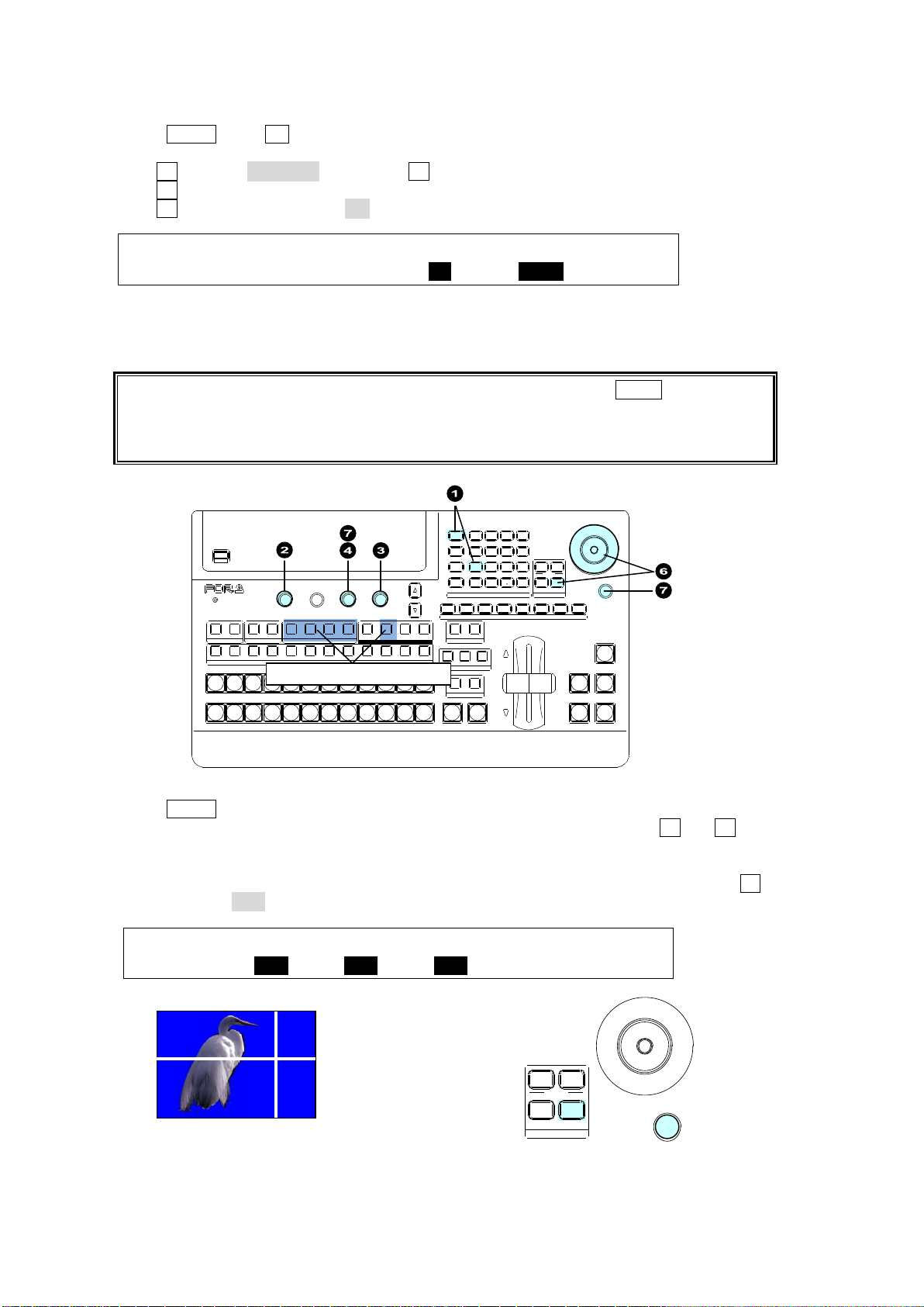
CHR KEY : POSITION :SELECT :SIGNAL : 1/2
AUTO CK :X=0 Y=0 : =ON : =IN01 :
If the preview picture is not displayed, press an AUX button, then PREV to display the
preview picture on the screen.
If you need to have a crosshair cursor also appear on the PGM screen, set PGM OUT to
ON in the [CHR KEY - AUTO CK] (2/2) menu.
CHR KEY : POSITION :SELECT :SIGNAL : 1/2
AUTO CK :X=100 Y=400 : =OFF : =IN01 :
USB MEMORY
DIGITAL VIDEO SWITCHER HVS-
XT
SIZE
(PUSH to DEF)
1 2 3 4 5 6 7 8
USER BUTTON
REV NOR/REV
DIRECTION
BLACK
TRANS
BKGD KEY1 KEY2
NEXT TRANSITION
MIX WIPE
KEY1 KEY2
TRANSITION TYPE
AUTO CUT DSK1 D SK2
ALARM
F1 F2 F3 F4
PAGE
1 1 1
1
2 2 2 3 4
2 3 4 5 6 7 8 9 10 11 12
KEYER DSK AUX
KEY/AUX
PGM PREV CLEAN MV
PGM
PST
1 2 3 4 5 6 7 8 9 10 11 12
MENU AT TA CH
DIRECT
PATT
DETACH
SETUP
KEY1
POSITION
POS R OT
2D DVE
WIPE
POS
MENU
JOYSTICK
8 9
4 5 6
STILL MATT FILE
KEY2 DSK1 DSK2
EVENT
MACRO
1 2 3
0
CLEAR
RECALL STORE
ENTER
CK EFFECT
TRANS RATE WIPE
SELECT/KEYPAD
±
7
Display the PREV iamge
SIZE
(PUSH to DEF)
POSITION
POS ROT
2D DVE
WIPE
POS
MENU
JOYSTICK
Move the crosshair with
the joystick along the X-Y
axes and twist the SIZE
control counter-clockwise
to create a Chroma key.
Preview screen
Creating a Chromakey
(1) Press MENU, then CK in the SELECT/KEYPAD block to display the [CHR KEY SETUP]
menu.
(2) Turn F1 to select AUTO CK, then press F1 to display the [CHR KEY - AUTO CK] menu.
(3) Turn F4 to select a signal used for chromakey under SIGNAL.
(4) Turn F3 to change SELECT to ON to activate the Auto Chroma key.
(5) KEY1 is displayed on the topmost layer of the Preview image and a cross hair cursor
appears. The current position of the cursor is displayed at POSITION X and Y in the [CHR
KEY - AUTO CK] menu.
(6) Press MENU in the joystick block. Move the joystick up, down left and right to move the
crosshair cursor onto the desired color. To precisely adjust the position, turn F1 and F2 to set
POSITION X and Y. Selecting a darker color makes adjustment easier.
(7) To create a chromakey, turn the SIZE control in the joystick counter-clockwise. Or, turn F3 to
set SELECT to OFF.
96
Page 97
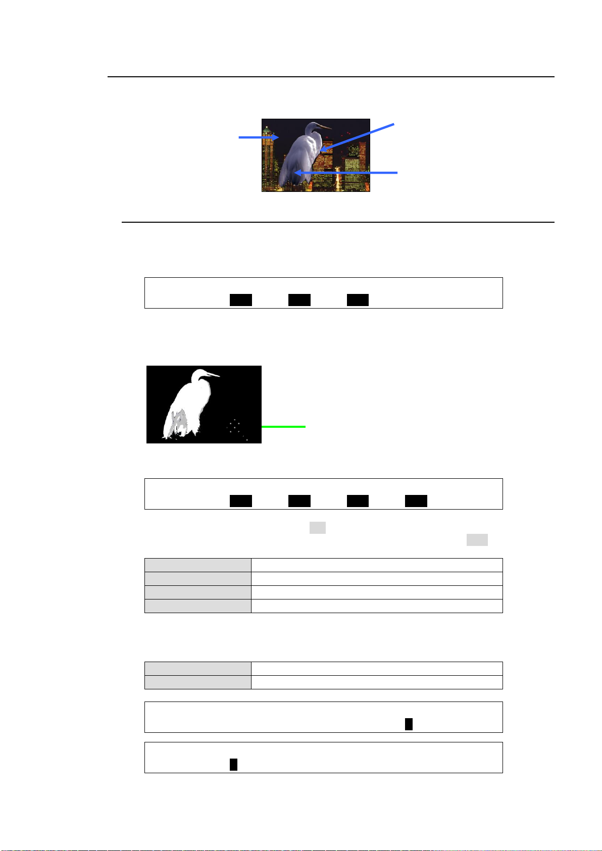
10-2. Adjusting Chromakey
CHR KEY : SAT : LUM : HUE : : 1/5
BKGND : =0.0 : =0.0 : =0.0 : :
CHR KEY : LUM : RED : GREEN : BLUE : 3/3
CORING : =OFF : =OFF : =OFF : =OFF :
LUM CORING
Effective for areas illuminated un-uniformly.
GREEN CORING
Effective for areas that are colored green unevenly.
BLUE CORING
Effective for the areas that are colored blue unevenly.
RED CORING
Effective for the areas that are colored red unevenly.
WHITE
Effective for bright walls and flooring
BLACK
Effective for dark walls and flooring.
CHR KEY :DENSITY:SOLDNES: : WHITE : 2/5
DENSITY : =0 : =0 : : =0 :
CHR KEY : BLACK : RED : GREEN : BLUE : 3/5
DENSITY : =0 : =0 : =0 : =0 :
Remove noises while monitoring
the key cut image.
Use EDGE SHRINK and
EDGE REPLACE to smooth
chroma key edges.
See section 10-2-3.
Use COLOR CANCEL and
SUPPRESSION to
eliminate or reduce color
noise on the bird.
See section 10-2-2.
Adjust key levels to
make the background
clear.
See section 10-2-1.
If the desired result is not achieved using the automatic chromakey generation procedure, fine
adjustments can be made as follows:
10-2-1. Adjusting Key Levels
(1) Adjusting the Chromakey Color
Open the [CHR KEY - ADJUST] (1/5) menu.
Finely adjust the chromakey color using the SAT, LUM and HUE parameters.
(2) Adjusting the KEY Cut Signal (Background)
Remove unwanted noise from the background areas (blue or green wall and floor) following
the procedure below.
(a) Open the [CHR KEY - MATTE] (3/3) menu.
Set the following 4 parameters to ON one by one and check the chromakey image.
If not noticeable changes appear in the image, return the setting to OFF.
(b) Reduce the WHITE or BLACK value in [CHR KEY - ADJUST] menu PAGE 2 or 3.
If not noticeable changes appear in the image, return the setting to the previous value.
97
Page 98
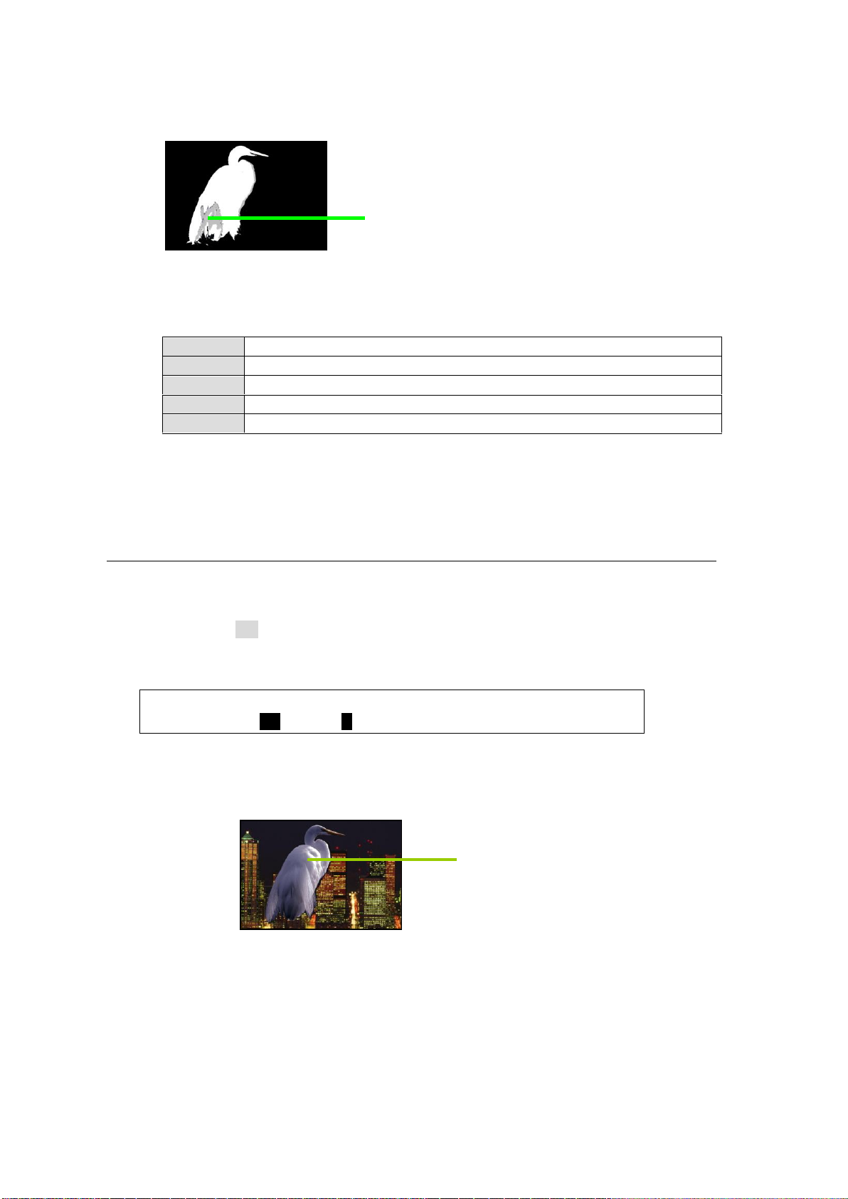
(3) Adjusting the KEY Cut Signal (Foreground)
WHITE
Effective for blue or green reflections on white hair, skin or clothes.
BLACK
Effective for blue or green reflections on black hair, skin or clothes.
RED
Effective for blue or green reflections on the reddish hair, skin or clothes.
GREEN
Effective for strong green reflections.
BLUE
Effective for strong blue reflections.
CHR KEY :SELECT :SUPPRES:SOLDNES: WHITE : 4/5
SUPPRES : =ON : =0 : =0 : =0 :
Remove noises while monitoring
the key cut image.
Reduce the background reflections
while monitoring the mixed image.
Remove unwanted noise from foreground areas (figures or objects) following the
procedure below.
(a) Use the parameters in the [CHR KEY - ADJUST] menu PAGE 2 and 3 to decrease the
level one by one and check the chromakey image. If not noticeable changes appear in
the image, return the setting to the previous value.
(4) If the key level of the Foreground is not high enough:
Gradually increase the SOLIDNESS value (about 10 for each) in PAGE 2 and repeat
Steps (2) and (3).
10-2-2. Adjusting the Foreground Image (Chromakey Color)
(1) Foreground (FILL) Coarse Adjustment
Adjust the foreground image coarsely following the procedure below.
Set SELECT to ON in the [CHR KEY - ADJUST] (4/5) menu.
Increase the SUPPRESSION value to reduce the blue or green reflections. At this
moment, you may substantially suppress reflections until unnecessary areas are affected.
(2) Foreground (FILL) Fine Adjustment
Finely reduce background reflections on the foreground image following the procedure
below.
Use the parameters in [CHR KEY - ADJUST] menu PAGE 4 and 5 (shown in the next
page) to reduce reflections.
98
Page 99
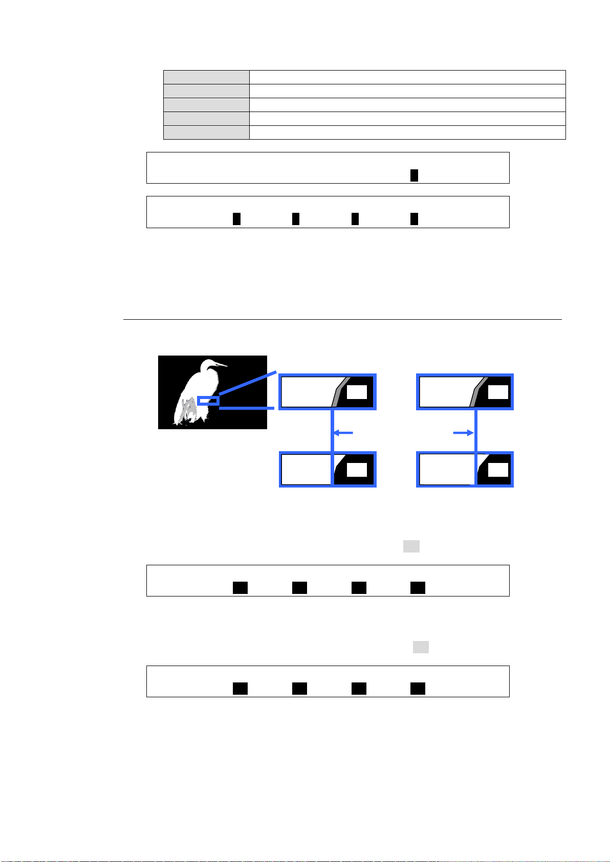
WHITE
Effective for reflections on white hair, skin or clothes.
BLACK
Effective for reflections on black hair, skin or clothes.
RED
Effective for reflections on reddish hair, skin or clothes.
BLUE
Effective for strong blue reflections.
GREEN
Effective for strong green reflections.
CHR KEY :SELECT :SUPPRES:SOLDNES: WHITE : 4/5
SUPPRES : =ON : =0 : =0 : =0 :
CHR KEY : BLACK : RED : GREEN : BLUE : 5/5
SUPPRES : =0 : =0 : =0 : =0 :
CHR KEY : EDGE SHRINK : 1/3
CK ADJT :T=ON B=ON L=ON R=ON :
CHR KEY : EDGE REPLACE : 2/2
FOREGND :T=ON B=ON L=ON R=ON :
EDGE SHRINK
FG
BG
FG
BG
EDGE REPLACE
FG
BG
FG
BG
(3) If the Color is not restored:
Gradually decrease the SOLIDNESS value (about 10 levels for each setting) and repeat
Step (2).
10-2-3. Adjusting Edges
EDGE SHRINK and EDGE REPLACE parameters allow users to adjust chromakey edges.
To Shrink Foreground Edges by Replacing them with the Background Video (EDGE
SHRINK)
Open the [CHR KEY - MATTE] (1/3) menu.
Set EDGE SHRINK (TOP, BOTTOM, LEFT, RIGHT) to ON.
To Replace Background Edges with the Foreground Video (EDGE REPLACE)
Open the [CHR KEY - FOREGND] (2/2) menu.
Set EDGE REPLACE (TOP, BOTTOM, LEFT, RIGHT) to ON.
99
Page 100
10-3. Chromakey Menu
CHR KEY :>AUTO CK >ADJUST >MATT >FORGRND
SETUP :>INIT
CHR KEY : SAT : LUM : HUE : : 1/5
BKGND : =0.0 : =0.0 : =0.0 : :
Parameter
Default
Setting range
Description
SAT
0.0
0.0-100.0
Finely adjusts the chromakey reference
color using these three parameters.
LUM
0.0
0.0-100.0
HUE
0.0
0.0-359.9
CHR KEY :DENSITY:SOLDNES: : WHITE : 2/5
DENSITY : =0 : =0 : : =0 :
CHR KEY : BLACK : RED : GREEN : BLUE : 3/5
DENSITY : =0 : =0 : =0 : =0 :
Parameter
Default
Setting range
Description
DENSITY
0
-100 to 100
Reduces edge spills (reflections) between
foreground and background adjusting the
density or solidness of the reference color.
SOLIDNESS
0
-100 to 100
WHITE
0
-100 to 100
Finely adjusts DENSITY of the referece
color.
BLACK
0
-100 to 100
RED
0
-100 to 100
GREEN
0
-100 to 100
BLUE
0
-100 to 100
CHR KEY :SELECT :SUPPRES:SOLDNES: WHITE : 4/5
SUPPRES : =OFF : =0 : =0 : =0 :
CHR KEY : BLACK : RED : GREEN : BLUE : 5/5
SUPPRES : =0 : =0 : =0 : =0 :
Parameter
Default
Setting range
Description
SELECT
OFF
OFF, ON
Sets Color Suppression ON/OFF.
If set to OFF, all other parameters in
PAGE 4 and 5 are disabled.
SUPPRESSION
0
-100 to 100
Applied when creating the foreground
(FILL) video.
This can be used to reduce background
reflections on the foreground.
SOLIDNESS
0
-100 to 100
Adjusts the color boundaries applied to
Color Suppression.
To display the Chromakey menu, press MENU, then CK in the SELECT/KEYPAD block. To
create and adjust a Chromakey, go to each submenu and set or adjust parameters.
10-3-1. [CHR KEY - ADJUST] Menu
100
 Loading...