

Page 1
OPERATION
MANUAL
FA-9600
Frame Synchronizer
FA-96PS
FA-964K
FA-96UDC
FA-96AHDR
FA-96AES-UBL
FA-96AES-UBLC
FA-96EX3G44-R
FA-96EX12G06
FA-96GPI
FA-96DB9-CBL
FA-96DIN4-CBL
2nd Edition - Rev. 4
Page 2
Edition Revision History
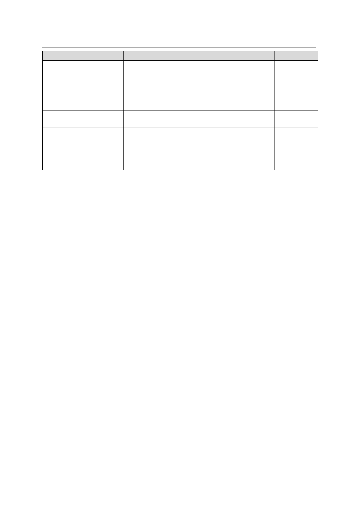
Edit.
Rev.
Date
Description
Section
1 - 2017/09/15
Supported 1080/59.94i, 1080/59.94p and 2160/59.94p.
2 2017/09/25
Supported multi-format video signals.
Supported HDMI, etc.
2 1 2017/11/17
Added FA-96DIN4-CBL.
Revised HDR related menus.
3-5
5-4 to 5-8
10-2-5
2 2 2017/12/22
Corrected GPI IN circuits.
Revised Loss Mode description.
3-3, 3-4
5-10, 10-2-1
2 3 2018/03/16
SNMP function added.
Factual errors corrected.
1-2, 12-2, 13
2 4 2018/04/16
SNMP function deleted.
FA-96EX12G06 option added.
Event data (csv files) description
3, 5, 10, 13
Appendix
2
Page 3
Precautions
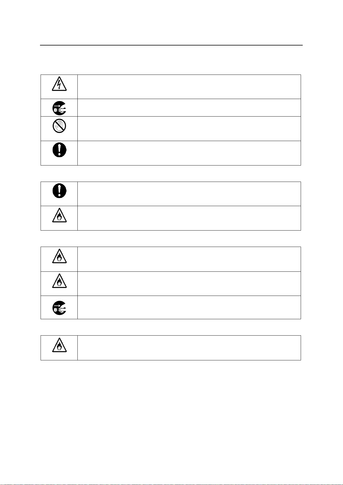
Caution
Operate unit only at the specified supply voltage.
Disconnect the power cord via the power plug only. Do not pull on the cable portion.
Stop
Do not place or drop heavy or sharp-edged objects on the power cord. A damaged
cord can cause fire or electrical shock hazards. Regularly check the power cord for
excessive wear or damage to avoid possible fire / electrical hazards.
Caution
Ensure the power cord is firmly plugged into the AC outlet.
Caution
Ensure the unit is properly grounded at all times to prevent electrical shock.
Hazard
Do not ground the unit to gas lines, units, or fixtures of an explosive or dangerous
nature.
Hazard
Do not operate the unit under hazardous or potentially explosive atmospheric
conditions. Doing so could result in fire, explosion, or other hazardous results.
Hazard
Do not allow liquids, metal pieces, or other foreign materials to enter the unit. Doing so
could result in fire, other hazards, or a unit malfunction.
If a foreign material does enter the unit, turn the power off and immediately disconnect
the power cord. Remove the material and contact an authorized service representative
if damage has occurred.
Hazard
Handle with care to avoid impact shock during transit, which may cause malfunction.
When you need to transport the unit, use the original or suitable alternative packing
material.
Important Safety Warnings
[Power]
[Grounding]
[Operation]
[Transportation]
3
Page 4
[Circuitry Access]
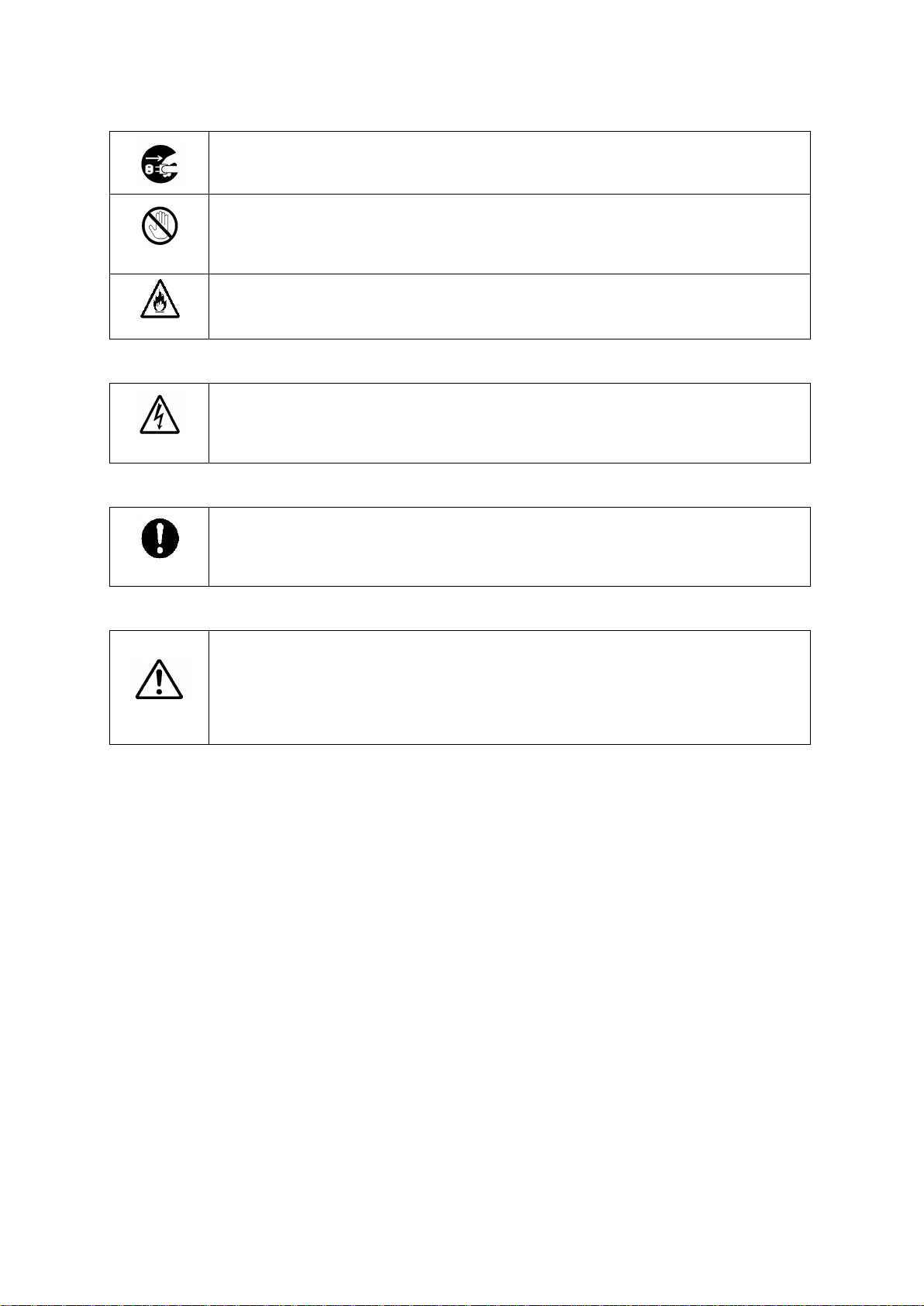
Do not remove covers, panels, casing, or access the circuitry with power applied to the
unit. Turn the power off and disconnect the power cord prior to removal. Internal
servicing / adjustment of unit should only be performed by qualified personnel.
Stop
Do not touch any parts / circuitry with a high heat factor.
Capacitors can retain enough electric charge to cause mild to serious shock, even after
the power has been disconnected. Capacitors associated with the power supply are
especially hazardous.
Hazard
Unit should not be operated or stored with cover, panels, and / or casing removed.
Operating the unit with circuitry exposed could result in electric shock / fire hazards or
a unit malfunction.
Caution
If abnormal odors or noises are noticed coming from the unit, immediately turn the
power off and disconnect the power cord to avoid potentially hazardous conditions. If
problems similar to the above occur, contact an authorized service representative
before attempting to operate the unit again.
Caution
To rack-mount or ground the unit, or to install rubber feet, do not use screws or
materials other than those supplied. Doing so may cause damage to the internal
circuits or components of the unit. If you remove the rubber feet that are attached to the
unit, do not reinsert the screws that secure the rubber feet.
Caution
Consumable items that are used in the unit must be periodically replaced. For further
details on which parts are consumables and when they should be replaced, refer to the
specifications at the end of the Operation Manual. Since the service life of the
consumables varies greatly depending on the environment in which they are used,
such items should be replaced at an early date. For details on replacing consumable
items, contact your dealer.
[Potential Hazards]
[Rack Mount Brackets, Ground Terminal, and Rubber Feet]
[Consumables]
4
Page 5
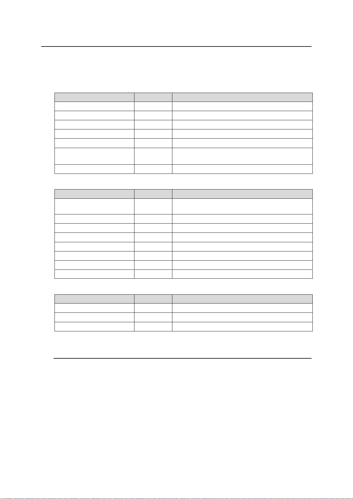
Upon Receipt
ITEM
QTY
REMARKS
FA-9600
1
AC Cord
1 set
(Includes an AC cord retaining clip)
Rubber foot
4
HDMI Cable Lacing Bracket
2 sets
Rack Mount Brackets
1 set
EIA standard type (Includes 4 screws)
CD-ROM
1
Windows GUI installation disc
User manuals (PDF) included
Quick Setup Guide
1
ITEM
QTY
REMARKS
FA-96PS
1 set
Redundant power supply unit (Including AC cord
and AC cord retaining clip)
FA-96AES-UBL
1
Digital audio (unbalanced) I/O card
FA-96AES-UBLC
1
Digital audio (unbalanced) I/O expansion cable
FA-96GPI
1-2
External I/O control card
FA-96EX3G44-R
1
3G-SDI I/O card
FA-96EX12G06
1
12G-SDI 6-output expansion card
FA-96DB9-CBL
1
GPI expansion cable
FA-96DIN4-CBL
1
LTC I/O expansion cable
ITEM
QTY
REMARKS
FA-964K
1
4K and 12G-SDI option
FA-96UDC
1
Up/down converter option
FA-96AHDR
1
Advanced functions for HDR
FA-9600 units and their accessories are fully inspected and adjusted prior to shipment. Check your
received items against the packing lists below. Check to ensure no damage has occurred during
shipment. If damage has occurred, or items are missing, inform your supplier immediately.
FA-9600 Box
Hardware Option
Software Option
Trademarks
* Microsoft, Windows and Internet Explorer are either registered trademarks or trademarks of
Microsoft Corporation in the United States and/or other countries
* Intel Core and Pentium are trademarks of Intel Corporation in the U.S. and/or other countries.
* Firefox is a registered trademark of the Mozilla Foundation.
* Dolby is a trademark of Dolby Laboratories Inc.
* All other trademarks are trademarks or registered trademarks of their respective owners.
5
Page 6
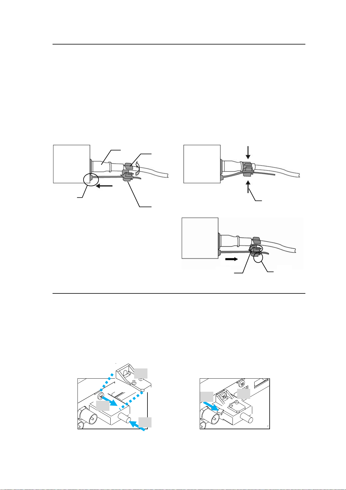
Installing the AC Cord Retention Clip
2)
4)
3)
5)
6)
1)
2)
5)
4)
1)
3)
2)
Secure the AC cord with the supplied ladder strap/retention clip assembly to prevent accidental
removal from the unit.
Installing the clip
1) Wrap the retention clip around the AC cord (with the anchor of the ladder strap toward the
unit).
2) Insert the anchor into the hole next to the AC IN socket.
3) Lightly fasten the clip around the AC cord.
4) Plug in the power cord.
5) Slide the clip on the ladder strap toward the plug.
6) Fasten the clip tightly.
7) Gently pull on the AC cord to ensure it is secured.
Unplugging the AC cord
1) Push the tab on the retention clip up to
unfasten the clip.
2) Push the tab on the ladder strap up and
slide the clip back.
3) Unplug the AC cord.
Installing the HDMI Cable Lacing Bracket
Secure the HDMI cable to the panel with the supplied cable lacing bracket.
1) Plug the HDMI cable into the HDMI connector on the rear panel.
2) Loosen (but do not remove) the screw above the connector.
3) Place the bracket on the screw, above the connector.
Tighten the screw (but not too tight) to secure the bracket.
4) Use the supplied tie wrap to secure the bracket to the connector.
5) Tighten the tie wrap and cut off any excess.
6
Page 7

Table of Contents
1. Prior to Starting ...................................................................................................................................11
1-1. Overview ...................................................................................................................................11
1-2. Key Features .............................................................................................................................11
2. Panel Descriptions ..............................................................................................................................13
2-1. Front Panel ................................................................................................................................13
2-2. Rear Panel ................................................................................................................................14
3. Option Slots ........................................................................................................................................15
3-1. FA-96EX3G44-R (SDI I/O Expansion) ......................................................................................15
3-2. FA-96EX12G06 (12G-SDI Output Expansion)..........................................................................15
3-3. FA-96AES-UBL and 96AES-UBLC (Audio Expansion) ............................................................16
3-4. FA-96DB9-CBL (7 GPI Input/Output) ........................................................................................17
3-5. FA-96GPI (10 Inputs and 10 Outputs) ......................................................................................19
3-6. FA-96DIN4-CBL (LTC I/O Expansion Cable)............................................................................21
4. Front Panel Operation ........................................................................................................................22
4-1. Basic Operation .........................................................................................................................22
4-2. Memory Access Icon .................................................................................................................23
5. Video Setting Menus ..........................................................................................................................24
5-1. VIDEO PREPROCESS AMPLIFIER .........................................................................................24
5-2. SPLIT MODE SELECT .............................................................................................................24
5-3. AREA MAKER (FA-96AHDR) ...................................................................................................25
5-4. INPUT / OUTPUT GAMMA/COLOR (UHD & HD) ....................................................................25
5-5. OOTF for HLG (FA-96AHDR) ...................................................................................................27
5-6. COLOR CORRECTION (Balance) ............................................................................................28
5-7. COLOR CORRECTION (Differential) .......................................................................................29
5-8. KNEE (RGB) CLIP (White/Black) ..............................................................................................29
5-9. YPbPr CLIP ...............................................................................................................................30
5-10. INPUT SELECT (Synchronizer) ..............................................................................................30
5-11. INPUT SELECT (Color Processor) .........................................................................................31
5-12. DYNAMIC RANGE GAIN CONTROL .....................................................................................31
5-13. OUTPUT SELECT ..................................................................................................................32
5-13-1. HDMI Output Restrictions ................................................................................................33
5-14. CONVERTER FORMAT (FA-96UDC) ....................................................................................34
5-14-1. Available Conversions on Converter 1 (FS1) ..................................................................35
5-14-2. Available Conversions on Converter 2 (FS2) ..................................................................36
5-15. CONVERTER / VIDEO FRAME DELAY (FA-96UDC) ............................................................37
5-16. FORMAT SETTING 1, 2, 3 (FS1) (FA-96UDC) ......................................................................38
5-17. I/P CONVERTER SETTING (FA-96UDC) ..............................................................................39
5-18. ANTIALIAS (FS1) (FA-96UDC) ...............................................................................................40
5-19. UHD UPCONVERSION 1, 2 (FS1) (FA-96UDC/964K) ..........................................................40
5-20. ANCILLARY MULTIPLEX .......................................................................................................41
5-21. VIDEO PAYLOAD ID ..............................................................................................................41
5-22. TIME CODE MULTIPLEX .......................................................................................................41
5-23. TIMECODE GENERATOR LTC 1, 2, 3 ..................................................................................42
5-24. TIMECODE GENERATOR VITC 1, 2, 3 .................................................................................43
5-25. LTC OUT SELECT (FA-96DIN4-CBL) ....................................................................................43
5-26. SYNCHRONIZED FORMAT ...................................................................................................44
5-27. SYNCHRONIZER ...................................................................................................................45
5-28. VIDEO FREEZE ......................................................................................................................45
5-29. SDI BYPASS ...........................................................................................................................46
5-30. VIDEO TEST SIGNAL .............................................................................................................46
5-31. VIDEO INPUT STATUS ..........................................................................................................47
5-32. PROCESSED SIGNAL STATUS ............................................................................................48
7
Page 8

5-33. SDI ERROR DETECTION ......................................................................................................48
5-34. VIDEO OUTPUT STATUS ......................................................................................................49
5-35. Payload ID (FA-96EX3G44-R) ................................................................................................49
5-36. INPUT TIMECODE DETECTION ...........................................................................................50
6. Audio Setting Menus ..........................................................................................................................51
6-1. AUDIO DEMUX .........................................................................................................................51
6-2. AUDIO MUX CLOCK (GROUP1-4) ..........................................................................................52
6-3. AUDIO MUX ENABLE (GROUP1-4) .........................................................................................52
6-4. EMD. AUDIO INPUT POLARITY ..............................................................................................52
6-5. SOURCE AUDIO SELECT .......................................................................................................53
6-6. SAMPLING RATE CONVERTER (SRC) ..................................................................................54
6-7. MONO SUM SETTINGS (1-16) ................................................................................................54
6-8. AUDIO DOWNMIX 1 and 2 .......................................................................................................55
6-9. EMB. AUDIO OUTPUT MAPPING ...........................................................................................57
6-10. AES AUDIO OUTPUT MAPPING ...........................................................................................57
6-11. AES INPUT HYSTERESIS .....................................................................................................58
6-12. AES TERMINAL IN/OUT SET ................................................................................................58
6-13. AES AUDIO INPUT POLARITY ..............................................................................................59
6-14. AUDIO OUTPUT GAIN ...........................................................................................................59
6-15. AUDIO INPUT DELAY ............................................................................................................60
6-16. AUDIO DELAY ADJUST FS SELECT ....................................................................................60
6-17. DOLBY E ALIGNMENT...........................................................................................................61
6-18. AUDIO OUTPUT CONV. DELAY MODE ................................................................................62
7. System Setting Menus ........................................................................................................................63
7-1. GPI UTILITY / INPUT / OUTPUT ..............................................................................................63
7-2. AUDIO SYSTEM 1, 2 ................................................................................................................65
7-3. AUDIO TEST SIGNAL ..............................................................................................................66
7-4. Remote Control Unit Setting .....................................................................................................66
7-5. FRONT PANEL SETTINGS ......................................................................................................66
7-6. NETWORK INFORMATION......................................................................................................67
7-7. EMB. AUDIO INPUT STATUS ..................................................................................................68
7-8. AES AUDIO INPUT STATUS....................................................................................................68
7-9. EMB. AUDIO OUT STATUS .....................................................................................................69
7-10. AES AUDIO OUT STATUS .....................................................................................................69
7-11. FAN / DC POWER / TEMP. STATUS .....................................................................................70
7-12. VERSION INFO. .....................................................................................................................70
7-13. UNIT INFO. .............................................................................................................................70
7-14. SLOT INFO. ............................................................................................................................71
7-15. SLOT D/E, POWER UNIT INFO. ............................................................................................71
7-16. SOFTWARE OPTION INFO. ..................................................................................................71
8. Event Memory ....................................................................................................................................72
8-1. LOAD EVENT MEMORY ..........................................................................................................72
8-2. SAVE EVENT MEMORY ..........................................................................................................72
8-3. START UP EVENT ...................................................................................................................72
8-4. Items Not Stored in Event Memory ...........................................................................................73
8-5. Notes on Event Memory............................................................................................................73
9. Windows GUI Setup ...........................................................................................................................74
9-1. System Requirements ...............................................................................................................74
9-2. Installing Windows GUI Software ..............................................................................................74
10. Windows GUI Control .......................................................................................................................76
10-1. Main Unit Tab (Editable Setting, Name Change) ....................................................................76
10-2. Video Tab Settings ..................................................................................................................77
10-2-1. Input Select ......................................................................................................................77
8
Page 9

10-2-2. Synchronizer ....................................................................................................................79
10-2-3. Converter 1, 2 ..................................................................................................................80
10-2-3-1. If Format Convert Selected (FA-96UDC): ................................................................80
10-2-3-2. If Delay Selected ......................................................................................................82
10-2-3-3. If Resize Selected (Converter 1 only).......................................................................82
10-2-3-4. If Noise Reduce Selected (Converter 1 only) ...........................................................84
10-2-4. Color Processor Select ....................................................................................................85
10-2-5. Color Processor 1, 2 ........................................................................................................85
10-2-5-1. Input / Output Gamma / Color ..................................................................................86
10-2-5-2. Pre Process Amp/Post Process Amp .......................................................................88
10-2-5-3. Dynamic Range Gain ...............................................................................................89
10-2-5-4. Differential Color Correct ..........................................................................................90
10-2-5-5. Knee (RGB) Clip .......................................................................................................91
10-2-5-6. Balance Color Correct ..............................................................................................92
10-2-5-7. YPbPr Clip ................................................................................................................93
10-2-5-8. Other .........................................................................................................................94
10-2-6. Ancillary 1/2 .....................................................................................................................95
10-2-6-1. If Multiplexer Selected ..............................................................................................95
10-2-6-2. If Time Code Selected: .............................................................................................96
10-2-7. Output Select ...................................................................................................................97
10-2-8. LTC OUT Select (FA-96DIN4-CBL) .................................................................................97
10-2-9. Bypass .............................................................................................................................97
10-2-10. Reference Select ...........................................................................................................98
10-2-11. Video Status...................................................................................................................98
10-3. Audio Tab Settings ..................................................................................................................99
10-3-1. INPUT Block (FS 1/2 IN) ..................................................................................................99
10-3-2. INPUT Block (AES IN and Option IN) ............................................................................100
10-3-3. Source Select.................................................................................................................101
10-3-4. Input Delay .....................................................................................................................102
10-3-5. Sampling Rate Converter ..............................................................................................102
10-3-6. Output Mapping 32x48 ..................................................................................................103
10-3-7. Mono Sum/Downmix/Mute/Test Signal .........................................................................104
10-3-7-1. If Downmix 1 or Downmix 2 Selected.....................................................................104
10-3-7-2. If Monosum Selected ..............................................................................................105
10-3-7-3. If Test / Mute Selected ...........................................................................................105
10-3-8. FS 1/2 Gain ....................................................................................................................106
10-3-9. AES Gain / Option Gain .................................................................................................106
10-3-10. FS 1/2 Output Delay ....................................................................................................107
10-3-11. AES/Option Output Delay ............................................................................................108
10-3-12. FS 1/2 OUT ..................................................................................................................109
10-3-13. Audio System ...............................................................................................................110
10-3-14. Input Status ..................................................................................................................111
10-3-15. Output Status ...............................................................................................................111
10-4. GPI Tab Settings ...................................................................................................................112
10-4-1. GPI Setting Screen (Slot B or Slot C) ............................................................................112
10-4-2. GPI Setting Screen (Slot E) ...........................................................................................113
10-5. Event Tab Settings ................................................................................................................114
10-6. Network Tab Settings ............................................................................................................115
10-7. Status Tab Display ................................................................................................................116
11. Web GUI Setup ..............................................................................................................................117
12. Web GUI Control ............................................................................................................................117
12-1. Unit Information .....................................................................................................................118
12-2. Network Settings ...................................................................................................................119
12-3. Event Data ............................................................................................................................120
12-4. Gamma Data .........................................................................................................................121
9
Page 10

12-5. Gamut Data ...........................................................................................................................121
12-6. LUT and GMT Files ...............................................................................................................122
13. Specifications and Dimensions ......................................................................................................124
13-1. Specifications ........................................................................................................................124
13-2. External Dimensions .............................................................................................................126
Appendix. Event Data (CSV File) .........................................................................................................127
10
Page 11
1. Prior to Starting
POWER
EVENT
LOCK
FS2
FS1
F4F3F2
UNITYUNITYUNITYUNITY
F1
GENLOCK
DC POWER
FAN ALARM
ON/OFFDISP
FA-9600
OPTION
MAPPING
CLIP
DELAY
OUTPUT
DWN MIX
CC
STATUSSYSTEM
GAIN
ANC
AES
INPUT
HDR/WCG
VIDEO
AUDIO
EMB
PROC
ANALOG
SETUP
FRAME SYNCHRONIZER
ON
OFF
AC100-240V 50/60Hz IN
12
IN2 OUT2a OUT2b
IN1 OUT1a OUT1b
IN OUT
1/2 7/85/63/4
3G/HD/SD-SDILAN 12G/6G/3G/HD/SD-SDI
GENLOCK IN
HDMI
DIGITAL AUDIO IN/OUT
B DA C
E
1-1. Overview
The FA-9600 multi-purpose signal processor provides dual channel SD/HD frame synchronizer,
with optionally supporting 4K UHD signals through Quad-Link 3G-SDI
and HDMI 2.0
(*1)
interfaces.
(*1,*2)
, Single-Link 12G-SDI
(*1)
More than a basic frame synchronizer, the FA-9600 is equipped with various converting capabilities
including up-/down-conversions
(*3)
. A newly developed color processing circuit supports the latest
gamut and dynamic range specifications, and allows to interchange various video signals. Offering
a wide range of audio processing, core features of remapping and gain adjustment.
The FA-9600 can be expanded by adding optional cards that make it an ideal standalone solution
at transmission centers, in mobile production trucks, production studios, news stations, and other
nonlinear editing and playout production environments.
(*1)
FA-964K required
(*2)
FA-96EX3G44-R required
(*3)
FA-96UDC required
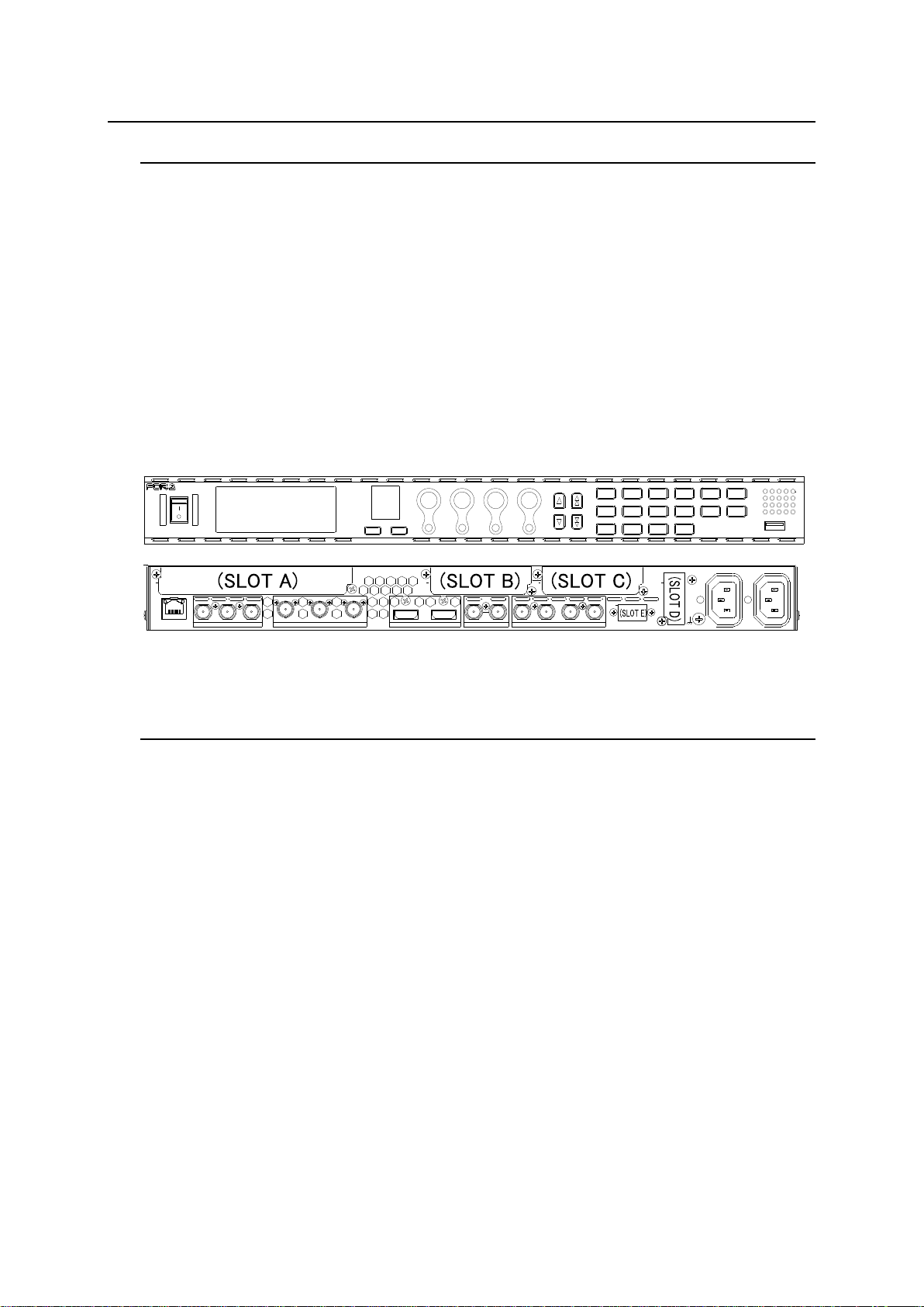
FA-9600 front and rear panels
1-2. Key Features
Dual channel signal processor (FS) with 2 inputs and 4 outputs for each
FA-964K option allows 4K/60p signals processing in either one of two FS channels
Optional cards allow the latest 12G-SDI interface
(*1)
and support from SD to 4K/60p
(*2)
HDMI ports as standard for various connectivity purposes (HDMI audio not supported)
New Color Processor
ITU-R BT.2020 (WCG) and ITU-R BT.709 processing and conversion.
Various HDR/ SDR EOTF and OETF reduce differences with external devices.
Custom EOTF / OETF log curves and color space data upload from computer
Dynamic Range conversion for Display light, OOTF (HLG)
(*4)
Optional FA-96UDC converter
Up-/down-/IP-conversions, ranging from SD to HD/4K
SQD / 2SI
(*2,*3)
and 3G-SDI Level-A/B
(*3)
conversion
4K conversion between Single-Link 12G-SDI and Quad-Link 3G-SDI (Gearbox)
(*2)
(*5)
Robust frame synchronizer with audio and SDI error correction
GUI software (full) and web browser (limited) control and SNMP monitoring (Support planned
in the future)
Miscellaneous options
-Digital audio input/output expansion
-3G-SDI input/output expansion
-12G-SDI 6-output expansion
-Redundant power supply system
-GPI input/output
11
Page 12

-GPI expansion cable
(*1)
SD/HD and 3G-SDI if no FA-964K option installed.
(*2)
FA-964K required
(*3)
FA-96UDC required
(*4)
FA-96AHDR required
(*5)
FA-964K and FA-96EX3G44-R required
12
Page 13
2. Panel Descriptions
POWER
EVENT
LOCK
FS2
FS1
F4F3F2
UNITYUNITYUNITYUNITY
F1
GENLOCK
DC POWER
FAN ALARM
ON/OFFDISP
FA-9600
OPTION
MAPPING
CLIP
DELAY
OUTPUT
DWN MIX
CC
STATUSSYSTEM
GAIN
ANC
AES
INPUT
HDR/WCG
VIDEO
AUDIO
EMB
PROC
ANALOG
SETUP
FRAME SYNCHRONIZER
ON
OFF
No
Name
Description
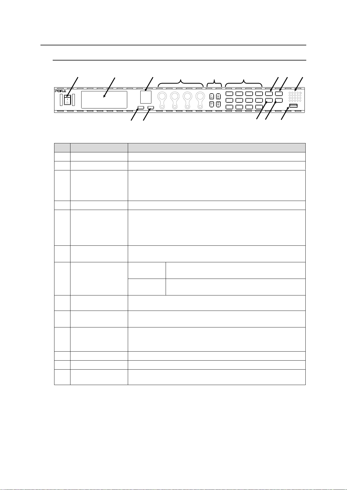
1
Power switch
Turns unit ON / OFF.
2
Color LCD panel
Displays menus and enters operational settings
3
Alarm display
FAN ALARM: Lit when a fan alarm occurs.
DC POWER: Lit when FA-96PS is installed and DC power error
occurs.
GENLOCK: Lit when an external reference signal is present.
4
DISP button
Switches the LCD panel display.
5
ON/OFF button
Turns the LCD panel display on/off.
Turn OFF the LCD display while unused. This will extend the life of
your LCD panel. Time out period can also be set, allowing you to
automatically turn off the LCD display when no panel operation is
detected for this period.
6
F1-F4 control knobs
UNITY buttons
Sets menu parameters by turning the control knobs.
UNITY buttons allow you to reset parameters to their default values.
7
Arrow buttons
Single
Selects a menu.
(The arrows light to indicate movable directions.)
Double
Selects a menu category.
(The arrows light to indicate movable directions.)
8
Menu buttons
Displays the top menu in each menu category on the LCD panel by
pressing a button.
9
FS1 button
FS2 button
Selects between FS1 and FS2.
10
LOCK button
Locks the front panel operation.
To lock the front panel, press and light the LOCK button.
To release the panel lock, press and hold the lit LOCK button.
11
EVENT button
Changes mode to event memory.
12
USB slot
Do not use.
13
Air supply vents
Internal cooling fans prevent overheating. Do not block the front,
rear or side vents with other equipment or objects.
3
13 1 2 6 9 8 7
10
4 9 5
11
12
2-1. Front Panel
* Install your FA-9600 unit in places where the LCD panel display can be correctly seen at the right angle,
due to viewing angle problems caused by LCD systems. Installing the unit into a rack in a too-high
position and viewing the screen from below may change contrast ratio and color values and distort
menus, depending on the viewing angle.
13
Page 14
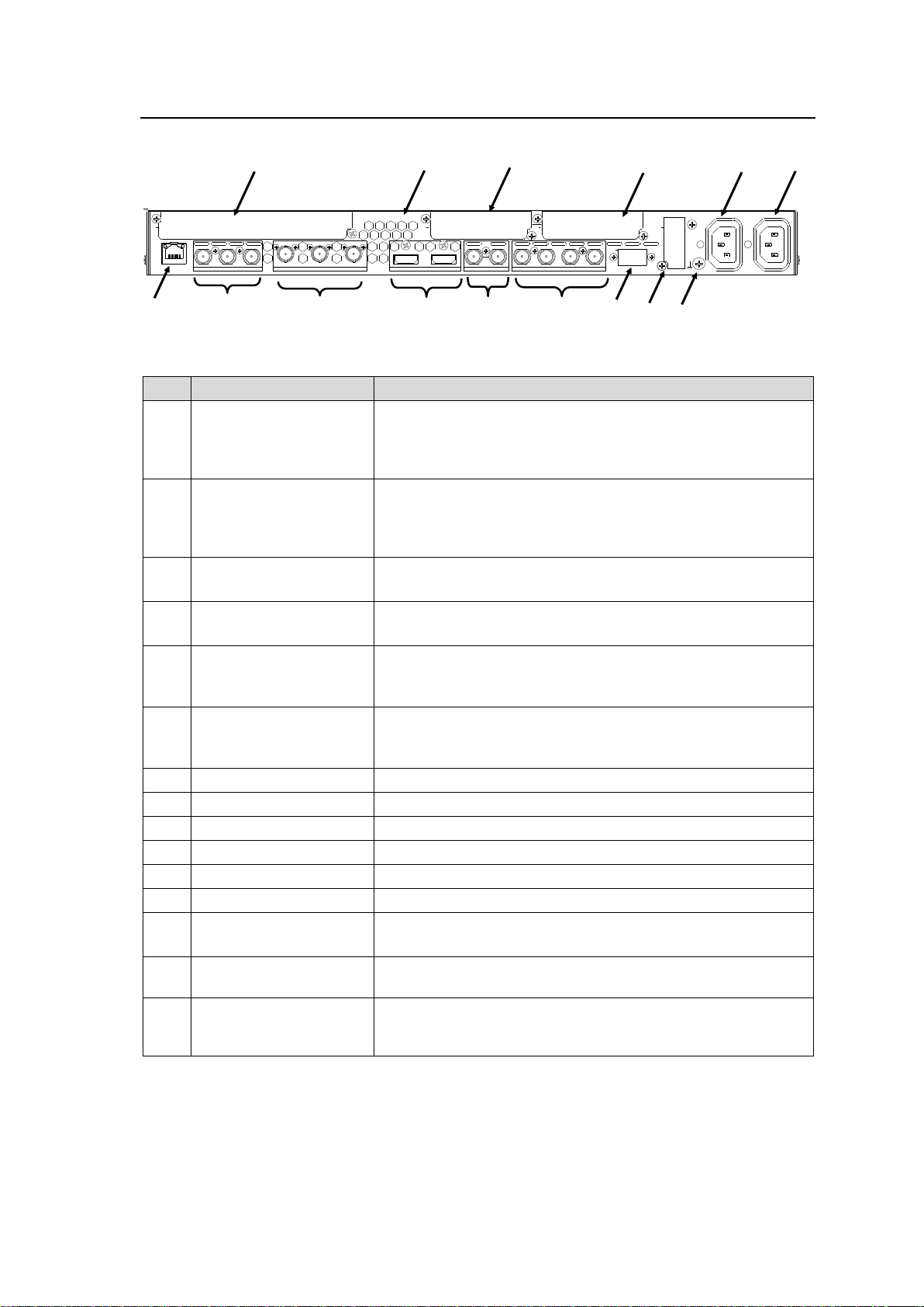
2-2. Rear Panel
AC100-240V 50/60Hz IN
12
IN2 OUT2a OUT2b
IN1 OUT1a OUT1b
IN OUT
1/2 7/85/63/4
3G/HD/SD-SDILAN 12G/6G/3G/HD/SD-SDI
GENLOCK IN
HDMI
DIGITAL AUDIO IN/OUT
B DA C
E
No
Name
Description
1
12G/6G/3G/HD/SD-SDI
IN 1
OUT 1a/1b
SDI video input and output, supporting transmission rates of
270 Mbps to 12 Gbps. (BNC)
* 12G-SDI supported with FA-964K option.
Up to 3G-SDI supported without FA-964K
2
3G/HD/SD-SDI
IN 2
OUT 2a/2b
SDI video input and output, supporting transmission rates of
270 Mbps to 3 Gbps. (BNC)
Bypassing relay from IN2 to OUT2a is possible when unit
power is off or via manual operation.
3
HDMI IN
HDMI OUT
HDMI input and output (Standard-A connectors)
* Audio unsupported
4
GENLOCK IN
External reference signal input (BNC)
Input a corresponding Black Burst or Tri-level Sync signal.
5
DIGITAL AUDIO
IN/OUT
1/2 to 7/8
Digital audio input / output.
Input or output selectable per 2-port pair. (BNC)
6
LAN
Ethernet port supporting 100/1000BASE-T (RJ-45)
To control the unit from a Windows GUI interface or remote
control unit, use an Ethernet hub to expand LAN ports.
7
SLOT-A
Option card installation slot for video expansion.
8
SLOT-B
Option card installation slot for audio expansion.
9
SLOT-C
Option card installation slot for audio expansion.
10
SLOT-D
Option card installation slot for control interface expansion.
11
SLOT E
Option card installation slot for control interface expansion
12
AC IN 1
AC power input. (100-240 V AC 50/60 Hz)
13
AC IN 2
AC power input when FA-96PS is installed.
(100-240 V AC 50/60 Hz)
14
Ground Terminal
Used to ground the unit to protect operators from static
electricity and/or electrical shock.
15
Air exhaust vents
Internal cooling fans prevent overheating. Do not block the
front, rear or side exhaust vents with other equipment or
objects.
9 8 7
15
12
13 1 3 4 5 6 14
10 2 11
(SLOT A)
(SLOT B)
(SLOT C)
14
Page 15
3. Option Slots
Product name
Description
Slot
FA-96PS
Power supply option to enable redundant power supply mode.
-
FA-964K
Allows you to use 12G-SDI signals.
(Software)
FA-96UDC
Allows you to perform up-, down- and cross conversions.
(Software)
FA-96AHDR
Allows you to use advanced color imaging features such as
HDR (High Dynamic Range) and WCG (Wide Color Gamut).
(Software)
FA-96EX3G44-R
Allows you to expand 3G/HD/SD-SDI input/output.
A
FA-96EX12G06
Allows you to add 6 outputs of 12G/3G/HD/SD-SDI.
A
FA-96AES-UBL
Allows you to expand digital audio input/output.
B
FA-96AES-UBLC
Allows you to expand digital audio input/output.
B or C
FA-96GPI
Allows you to add a GPI interface (10-input/10-output)
B or C
FA-96DIN4-CBL
Allows you to expand LTC input/output (1-input/1-output)
D
FA-96DB9-CBL
Allows you to add a GPI interface (7 input or output)
E
12G/6G/3G/HD/SD-SDI
OUT1a
OUT1b
OUT2 OUT3a OUT3b OUT4
The FA-9600 can be upgraded by installing optional modules into Slots A to C.
Install option cards into the correct slots since available slots are defined depending on the option type
cards as shown below.
FA-9600 option list
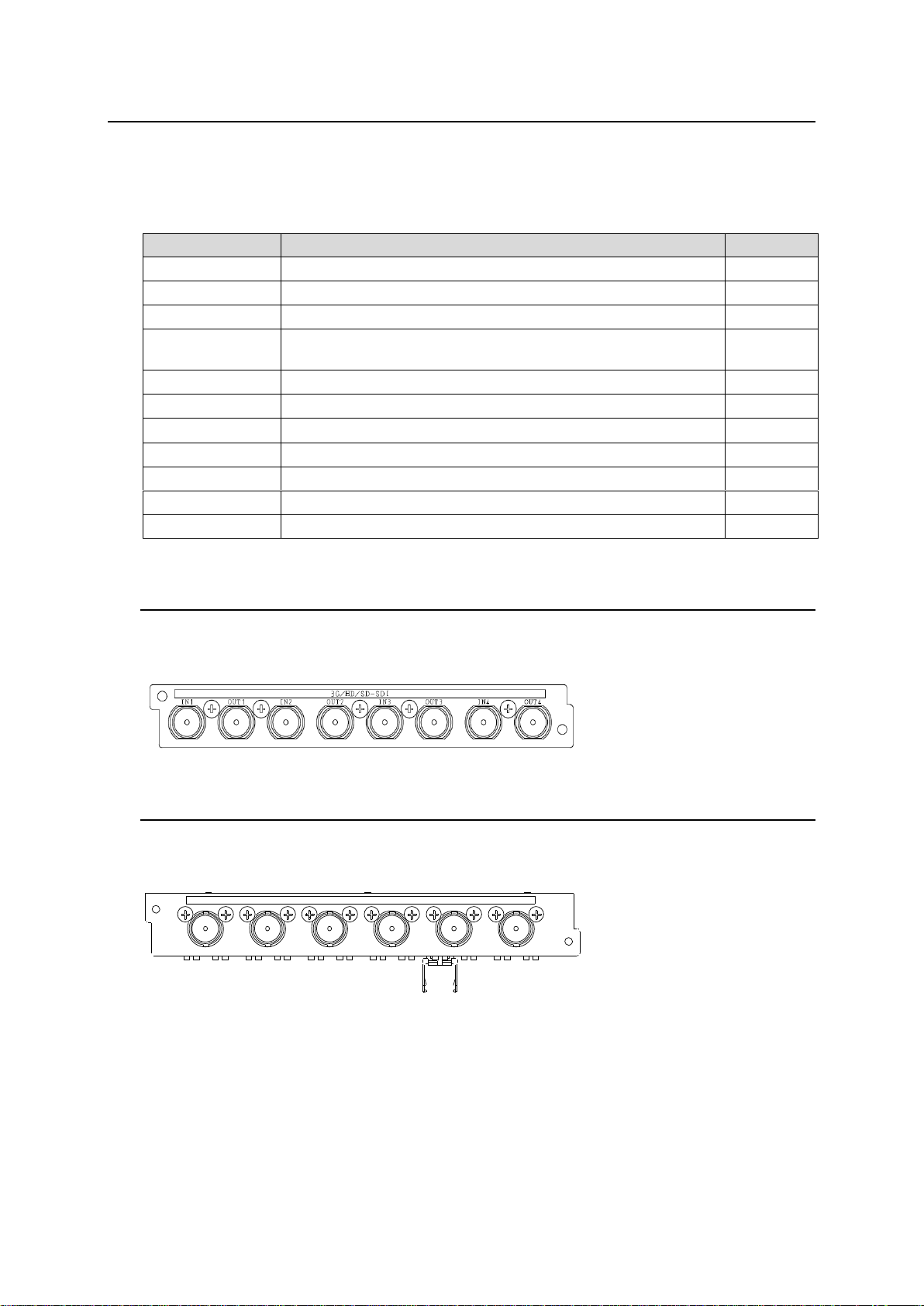
3-1. FA-96EX3G44-R (SDI I/O Expansion)
SDI expansion card that supports 4-input/4-output 3G/HD/SD-SDI and allows relay bypass.
Install the card to Slot A.
3-2. FA-96EX12G06 (12G-SDI Output Expansion)
SDI output expansion card that supports 12G/3G/HD/SD-SDI. Up to 6 output can be added.
Install the card to Slot A.
15
Page 16
3-3. FA-96AES-UBL and 96AES-UBLC (Audio Expansion)
1/2 3/4 5/6 7/8
DIGITAL AUDIO IN/OUT
3/4 5/6 7/81/2
DIGITAL AUDIO OUT
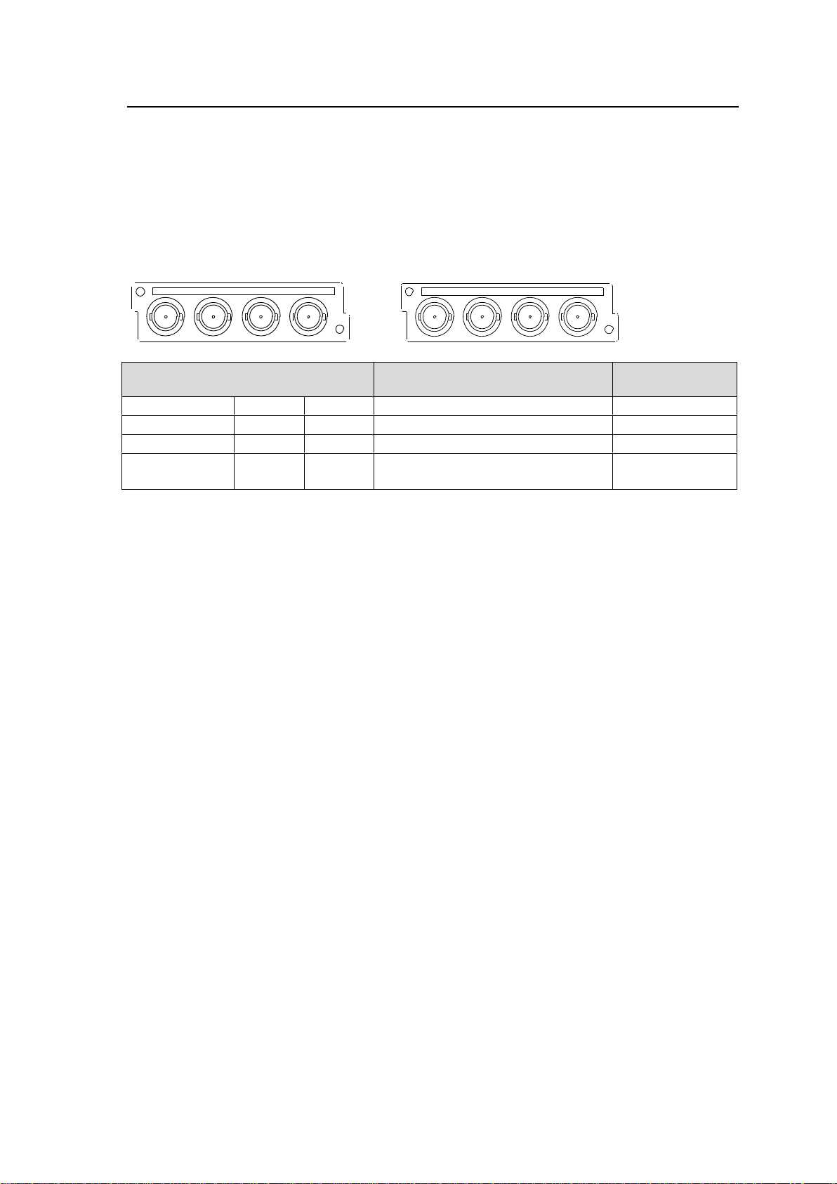
Installed AES card/cable
Input / Output
Total number of
channels
Standard AES
- - I/O selectable per 4 channels
8
Standard AES
UBL - I/O selectable per 4 channels
16
Standard AES
-
UBLC
Std AES: 8-ch input, UBLC: 8-ch output
16
Standard AES
UBL
UBLC
Std AES: 8-ch input, UBLC: 8-ch output
UBL: I/O selectable per 4 channels
24
AES/EBU (digital) audio expansion card and cable that can add 4 ports respectively. Install a card
into Slot B and a cable into Slot B or C.
Installing an FA-96AES-UBL card adds 4 ports (8 channels) for input or output. Input or output
can be selected per 2 ports (4 channels) in the AES TERMINAL IN/OUT SET menu (see Sec. 6-12)
in the same manner as standard AES ports.
Installing an FA-96AES-UBLC cable adds 4 ports (8 channels) for output and sets all standard
AES ports to input.
FA-96AES-UBL (Expansion card) FA-96AES-UBLC (Expansion cable)
16
Page 17
3-4. FA-96DB9-CBL (7 GPI Input/Output)
Pin No.
Description
1
DC IN or DC OUT
* DC IN or OUT (+5.0 V) set by the jumper pin: JP1 (See the next page.)
* Factory default: DC OUT
* Total max load current is 200 mA.
2
GPI 1 (Input or output)
3
GPI 2 (Input or output)
4
GPI 3 (Input or output)
5
GPI 4 (Input or output)
6
GPI 5 (Input or output)
7
GPI 6 (Input or output)
8
GPI 7 (Input or output)
9
GND (Signal ground)
1
3
PIN 9
PIN 2-8
FA-9600
+5.0V
JP1
PIN 1
FUSE
10 kΩ
3 4 5 1 2 8 9 7 6
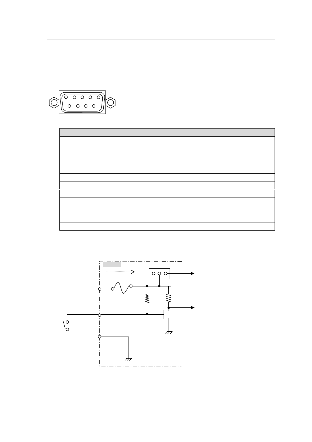
A GPI expansion cable that can be add 7 GPI input/output. Install the option to Slot E.
The FA-96DB9-CBL connector pin assignments are as shown in the table below.
Use the menu to select input or output function for each pin. (See Sec. 7-1. “GPI UTILITY / INPUT
/ OUTPUT.”)
FA-96DB9-CBL Connector (9-pin D-sub, female, with inch screws)
Connector pin assignments
GPI Input Circuit
Function ON: Pin shorted to ground
Function OFF: Pin opened
17
Page 18
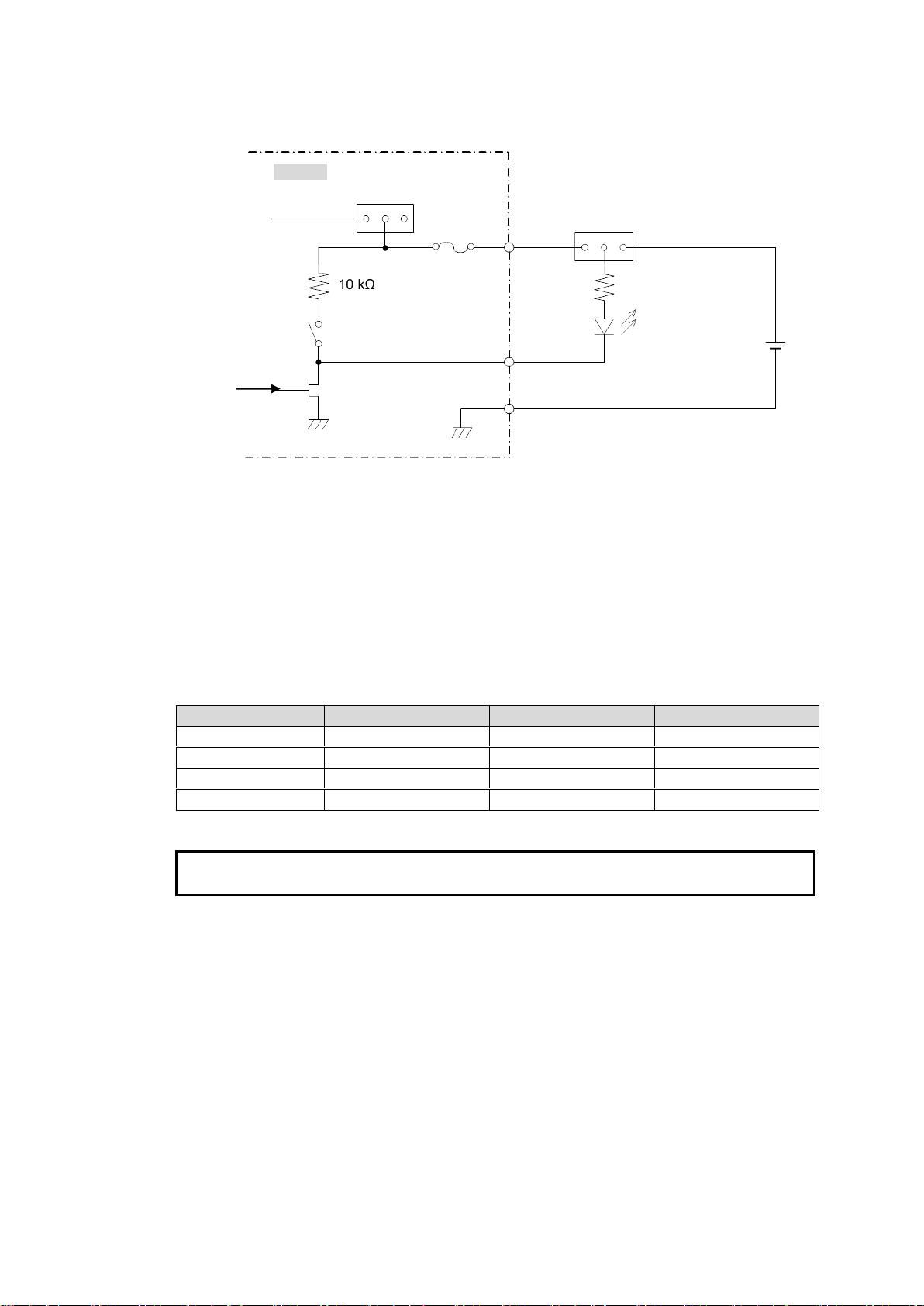
GPI Output Circuit
Dipswitch pin
Controlled output
Dipswitch pin
Controlled output
S2-1
GPI OUT 1
S2-5
GPI OUT 5
S2-2
GPI OUT 2
S2-6
GPI OUT 6
S2-3
GPI OUT 3
S2-7
GPI OUT 7
S2-4
GPI OUT 4
IMPORTANT
Loadable current for the GPI output circuit: Max 50 mA.
External power supply voltage: +5 to +24V DC
10 kΩ
JP1
+5.0V
FUSE
PIN 1
PIN 2-8
+5-24V
External power
S2-1-7
Max 50 mA
PIN 9
3
1
FA-9600
Jumper setting
JP1: Switches between internal and external power.
1-2 shorted: DC IN (External power input)
2-3 shorted: DC OUT (Internal power output)
Dipswitch settings
S2: 7 dipswitch pins turn output on/off.
Off: Push-pull output (factory default setting)
On: Open-drain output
Dipswitch Pin Assignments
18
Page 19
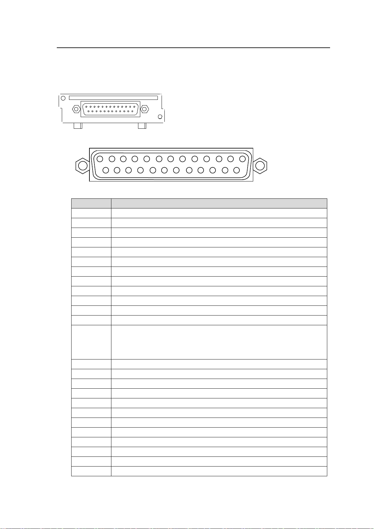
3-5. FA-96GPI (10 Inputs and 10 Outputs)
GPI
Pin No.
Description
1
GND (Signal ground)
2
GPI OUT 1
3
GPI OUT 2
4
GPI OUT 3
5
GPI OUT 4
6
GPI OUT 5
7
GND (Signal ground)
8
GPI IN 1
9
GPI IN 2
10
GPI IN 3
11
GPI IN 4
12
GPI IN 5
13
DC IN or DC OUT
* DC IN or OUT (+5.0 V) set by the jumper pin: JP1 (See the next page.)
* Factory default: DC OUT
* Total max load current is 500 mA.
14
GPI OUT 6
15
GPI OUT 7
16
GPI OUT 8
17
GPI OUT 9
18
GPI OUT 10
19
GND (Signal ground)
20
GPI IN 6
21
GPI IN 7
22
GPI IN 8
23
GPI IN 9
24
GPI IN 10
25
NC
2 3 1 5 4 6 7 8 9
10
11
12
13
15
16
17
18
19
20
21
22
23
24
25
14
1
GPI interface card that provides 10 inputs and 10 outputs.
Each input/output terminal is function-assignable. To assign functions, see Sec. 7-1 “GPI
UTILITY/INPUT/OUTPUT (FA-96GPI Slot B/C).”
Install to Slot B or C.
FA-10GPI Connector (25-pin D-sub, female, with inch screws)
Connector pin assignments
19
Page 20
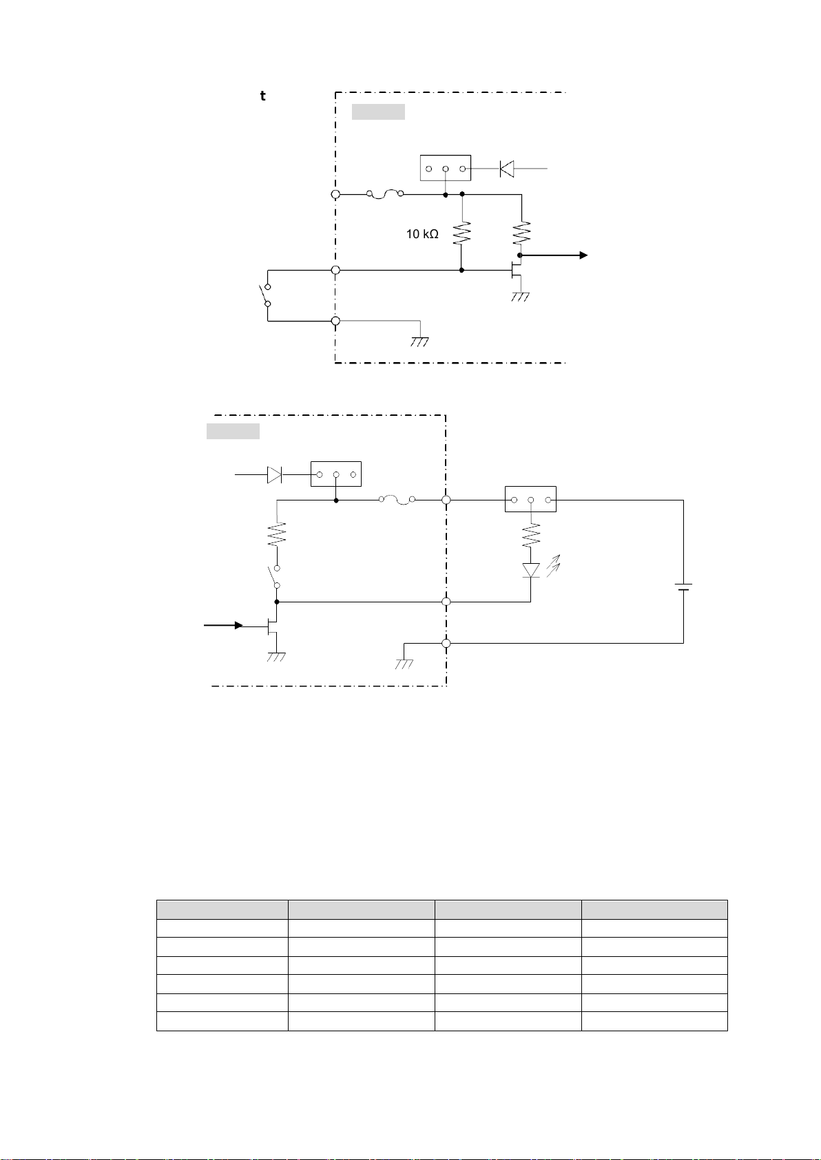
GPI Input Circuit
Dipswitch pin
Controlled output
Dipswitch pin
Controlled output
SW1-1
GPI OUT 1
SW2-1
GPI OUT 5
SW1-2
GPI OUT 2
SW2-2
GPI OUT 6
SW1-3
GPI OUT 3
SW2-3
GPI OUT 7
SW1-4
GPI OUT 4
SW2-4
GPI OUT 8
SW3-1
GPI OUT 9
SW3-2
GPI OUT 10
10 kΩ
JP1
+5.0 V
FUSE
1
3
13 PIN
PIN 8-12, 20-24
PIN 1, 7, 19
FA-9600
JP1
+5.0 V
FUSE
PIN 13
PIN 2-6, 14-18
+5-24 V
External power
SW1 (1-4)
SW2 (1-4)
SW3 (1-2)
Max. 50 mA
PIN 1, 7, 19
3
1
FA-9600
10 kΩ
GPI Output Circuit
Jumper setting
JP1: Switches between internal and external power.
1-2 shorted: DC IN (External power input)
2-3 shorted: DC OUT (Internal power output)
Dipswitch settings
SW1(1-4),SW2(1-4), SW3(1-2): 10 dipswitch pins turn output on/off.
Off: Push-pull output (factory default setting)
On: Open-drain output
Dipswitch Pin Assignments
20
Page 21
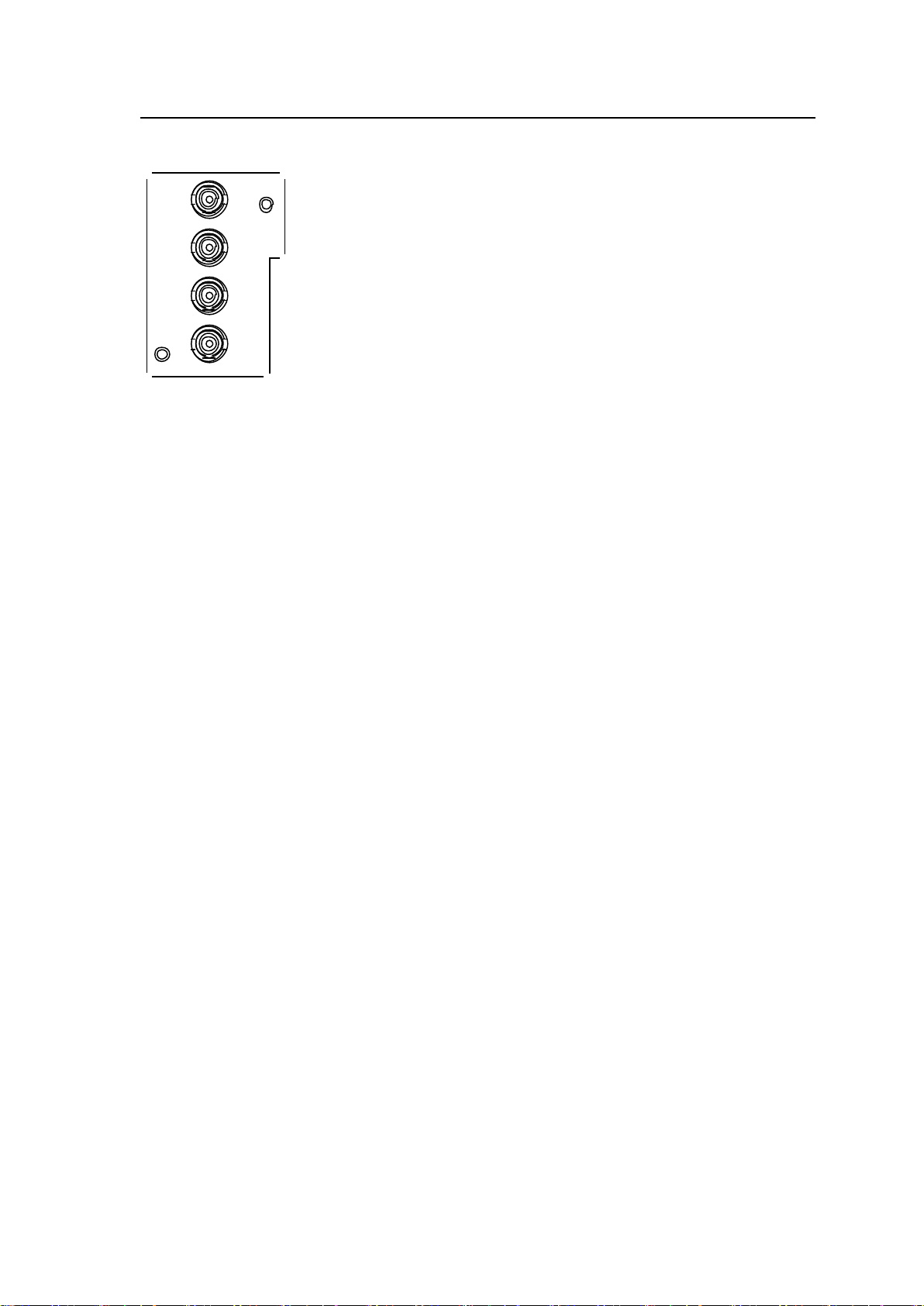
3-6. FA-96DIN4-CBL (LTC I/O Expansion Cable)
I/O
LTC
IN
LTC
OUT
I/O
1
2
The LTC Expansion Cable allows you to add one LTC input and one LTC output. Install the cable
into Slot D.
* I/O1 and I/O2 are reserved for future use.
21
Page 22
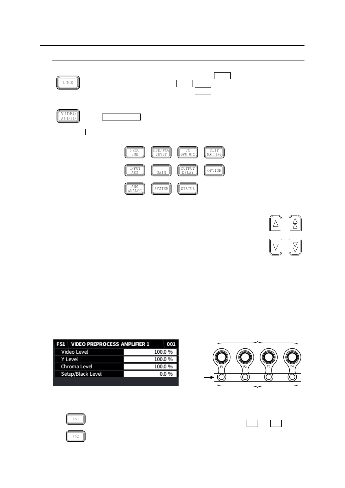
4. Front Panel Operation
VIDEO/AUDIO
selection button
UNITY
Outlines are lit when settable.
Lit orange to indicate default values.
4-1. Basic Operation
Lock Button
All front panel operations are disabled when the LOCK button is lit.
To lock the front panel, press the LOCK button. The button light will turn on.
To unlock the front panel, hold down the LOCK button. The button will turn off.
Selecting a Menu
Both Video and Audio menus are assigned to some menu buttons.
The VIDEO/AUDIO button allows you to select Video or Audio menus and lights to
indicate which menu is enabled. The blue button light indicates Video menus (upper
menu labels) are enabled, and the orange light indicates Audio menus (bottom menu
labels) are enabled. Press the button to change the light color.
Menu buttons
Arrow buttons
Moving between menu pages
Use up/down double-arrow buttons to move between menu pages.
Moving between menu items
Use up/down single-arrow buttons to move between menu items
in menu pages. The buttons are lit if available and unlit if unavailable.
Setting Parameters
Pressing a menu button displays the corresponding menu as shown below on the menu
display and function button (F1-F4) outlines will light if the buttons are available for menu
setting. Lighting orange indicates that the selected parameter is set to default.
To change parameter values, press the corresponding function buttons. (A buzzer sound will be
heard if the setting value exceeds the allowable parameter range.)
To set a parameter to its default value, press the corresponding UNITY button below F1-F4. (In
such cases, repressing the UNITY button reverts it to the previous state.)
LCD display
FS1/FS2 Selection Buttons
“FS1” and “FS2” in front of menu titles indicate that the menu can be set
independently between FS1 and FS2. Select an FS using the FS1 and FS2 buttons.
22
Page 23
4-2. Memory Access Icon
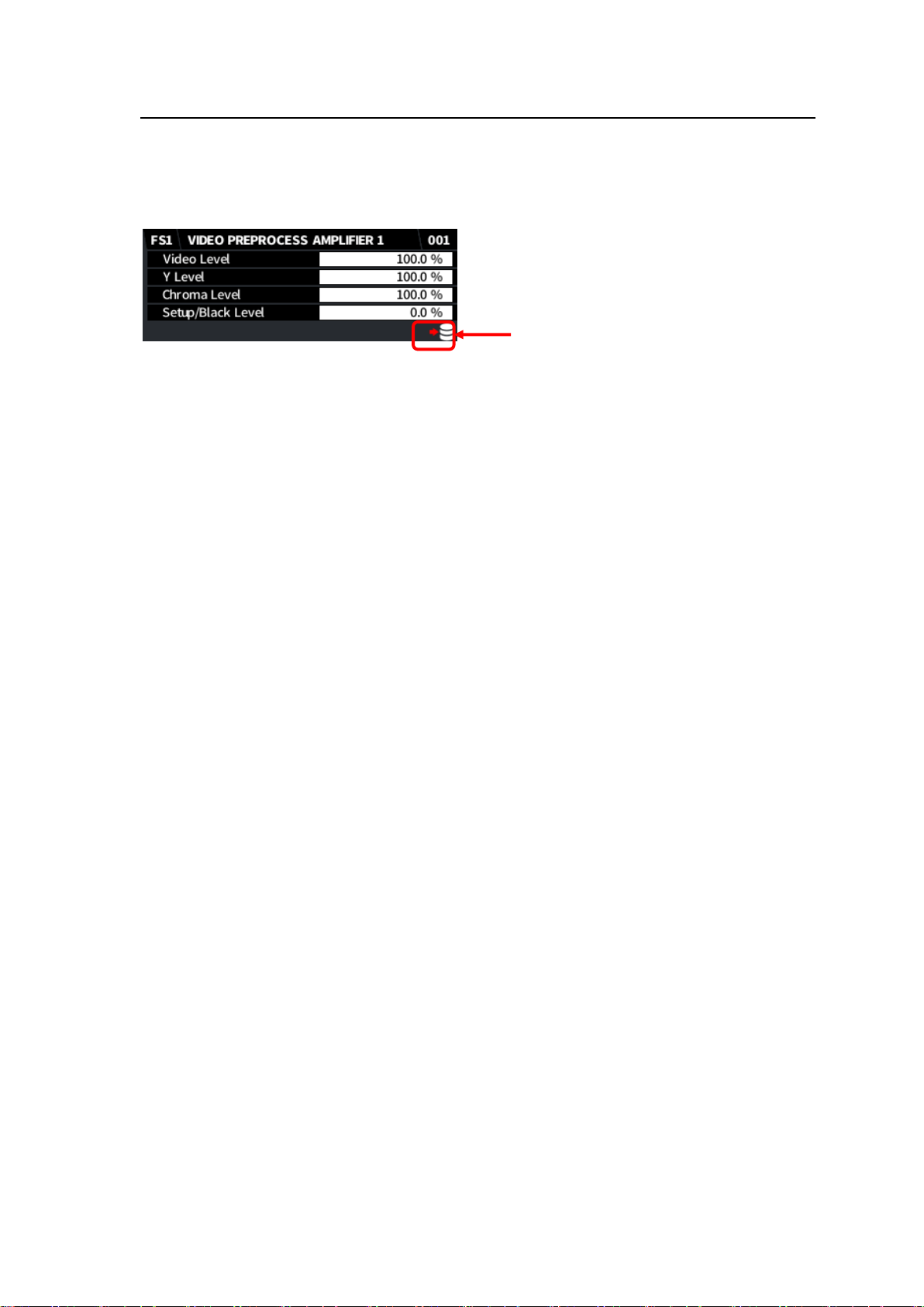
Access icon
An access icon as shown below will appear on the bottom-right corner of the menu screen while the
built-in memory is being accessed, such as during power-on or event operation.
Do not power off FA-9600 units while the icon is displayed. Otherwise, memory data may be lost or
broken.
23
Page 24
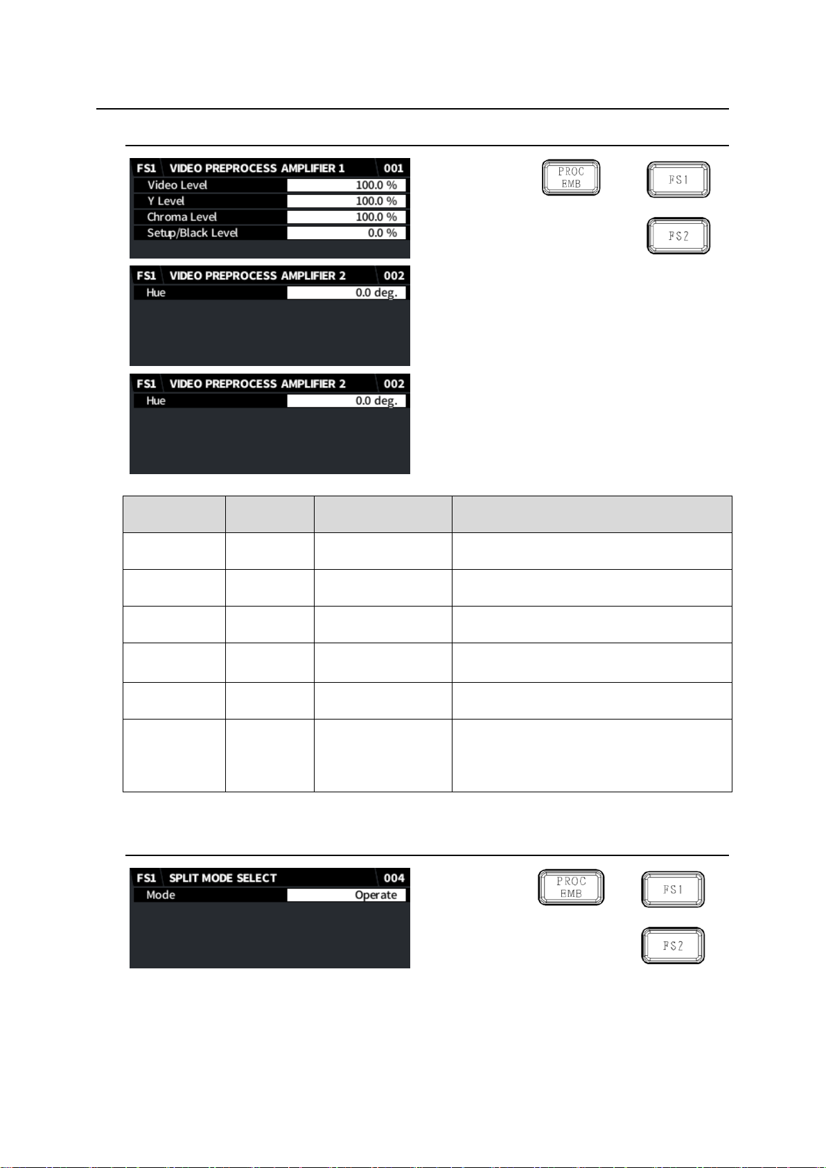
5. Video Setting Menus
Item
Default
Setting range
(Steps)
Description
Video Level
100.0 %
0.0 - 200.0 %
(0.1 %)
Adjusts the video level.
Y Level
100.0 %
0.0 - 200.0 %
(0.1 %)
Adjusts the luminance level.
Chroma Level
100.0 %
0.0 - 200.0 %
(0.1 %)
Adjusts the chrominance level.
Setup/Black
Level
0.0 %
-20.0 - 100.0 %
(0.1 %)
Adjusts the black level.
Hue
0.0 deg.
-179.8 - 180.0 deg.
(0.2 deg.)
Adjusts the chroma phase.
Control Select
(FA-96AHDR)
Preprocess
Preprocess
Postprocess
Selects where the Proc Amp process is
located.
Preprocess: Before Color Correction.
Postprocess: After Color Correction
5-1. VIDEO PREPROCESS AMPLIFIER
5-2. SPLIT MODE SELECT
24
Page 25
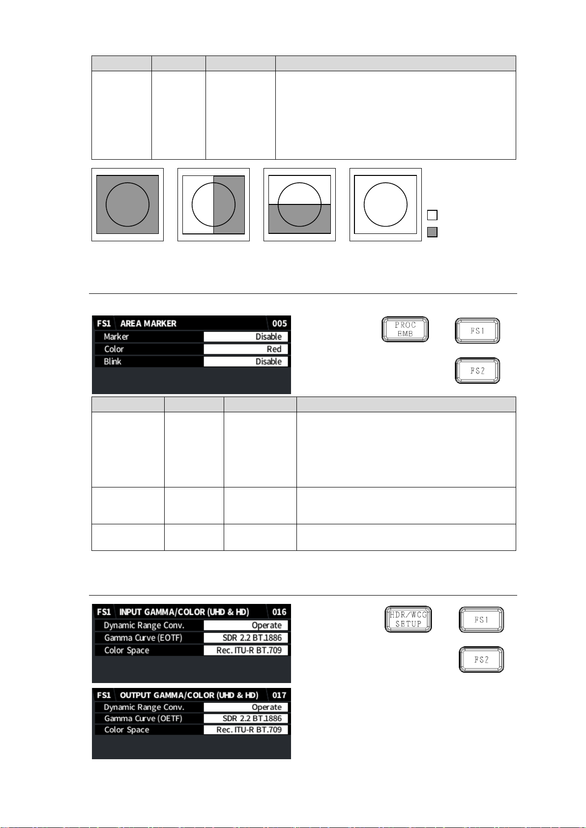
Item
Default
Setting range
Description
Mode
Operate
Operate
V-Split
H-Split
Bypass
Selects the output image display method.
Operate: Displays the image after correction.
H-Split: Splits the screen horizontally and displays
images before and after correction.
V-Split: Splits the screen vertically and displays
images before and after correction.
Bypass: Displays the input image without correction.
Item
Default
Setting range
Description
Marker
Disable
Disable
Luminance
Gamut
Selects the marker mode.
Disable: Plots no makers.
Luminance: Marks pixels above the high
threshold when enabling RGB Clip.
Gamut: Marks pixels whose RGB values exceed
the range between 0 and 1.0.
Color
Red
Red
Green
Blue
Selects the marker color.
Blink
Disable
Disable
Enable
Toggles marker flashing on/off.
H-Split
Operate
V-Split
Bypass
Input image
Corrected image
5-3. AREA MAKER (FA-96AHDR)
This menu requires FA-96AHDR optional software.
5-4. INPUT / OUTPUT GAMMA/COLOR (UHD & HD)
25
Page 26
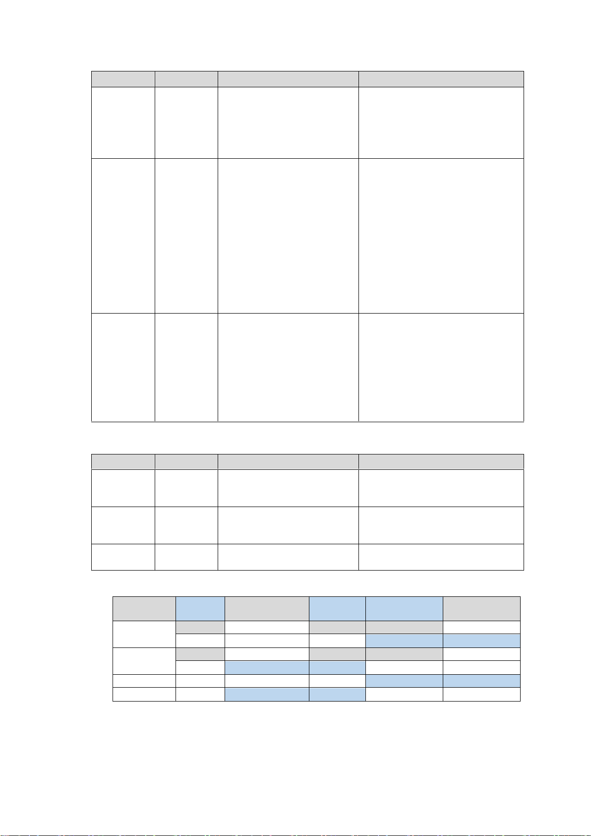
INPUT GAMMA/COLOR (UHD & HD)
Item
Default
Setting range
Description
Dynamic
Range
Conv.
Bypass
Bypass
Operate
Operate: Performs the Dynamic
Range/Color Space
processing and enables the
Gamma Curve and Color
Space settings.
Bypass: Bypasses the processing.
Gamma
Curve
(EOTF)
User 01:
SDR 2.2
BT.1886
User 01: SDR 2.2 BT.1886
User 02: SDR 2.4 BT.1886
User 03: HLG BT.2100
User 04: HLG (RGB SG1.2)
User 05: HLG (RGB SG1.4)
User 06: ST 2084 (PQ)
User 07: SDR 2.2 BT.709
User 08: S-Log3
User 09: Canon Log 2
User 10: SDR 2.4 BT.1886
Selects a gamma curve for input.
(See GAMMA / COLOR Setting
Examples <p. 26>)
Gamma settings as shown at left
are respectively stored in files
named User 01 to User 10.
Gamma setting names and content
can be changed by editing files in
the Web GUI. (See Sec. 12-4
“Gamma Data.”)
These settings are shared by both
input and output gamma settings.
Color
Space
Rec. ITU-R
BT.709
Rec. ITU-R BT.709
Rec. ITU-R BT.2020
User 01: S-Gamut/Gamut3
User 02
User 03
User 04
User 05
Selects a color space for input.
User 01-05 Gamut settings are
stored in files and these names and
content can be changed by editing
files in the Web GUI. (See Sec.
12-5. “Gamut Data”)
These settings are shared by both
input and output gamut settings.
Item
Default
Setting range
Description
Dynamic
Range
Conv.
Bypass
Bypass
Operate
(Same setting as in the INPUT
GAMMA/ COLOR menu above)
Gamma
Curve
(OETF)
User 01:
SDR 2.2
BT.1886
(Same as INPUT GAMMA /
COLOR menu)
Selects a gamma curve for output.
(See GAMMA / COLOR Setting
Examples below <p. 26>)
Color
Space
Rec. ITU-R
BT. 709
(Same as INPUT GAMMA /
COLOR menu)
Selects a color space for output.
Conversion
OOTF for
HLG
(*1)
Input Gamma
Curve
OOTF
(*2)
(HLG)
Inverse OOTF
(*3)
(HLG)
Output Gamma
Curve
SDR→HLG
Disable
SDR 2.2 BT.709
Disable
Disable
HLG BT.2100
Enable
SDR 2.4 BT.1886
-
Inverse OOTF
HLG BT.2100
HLG→SDR
Disable
HLG BT.2100
Disable
Disable
SDR 2.2 BT.709
Enable
HLG BT.2100
OOTF
-
SDR 2.4 BT.1886
PQ→HLG
Enable
ST 2084 (PQ)
-
Inverse OOTF
HLG BT.2100
HLG→PQ
Enable
HLG BT.2100
OOTF
-
ST 2084 (PQ)
OUTPUT GAMMA/COLOR (UHD & HD)
GAMMA / COLOR Setting Examples
(*1) See Sec. 5-5. “OOTF for HLG - Mode.”
(*2) See Sec. 5-5. “OOTF for HLG - INPUT SIDE.”
(*3) See Sec. 5-5. ““OOTF for HLG - OUTPUT SIDE.”
26
Page 27
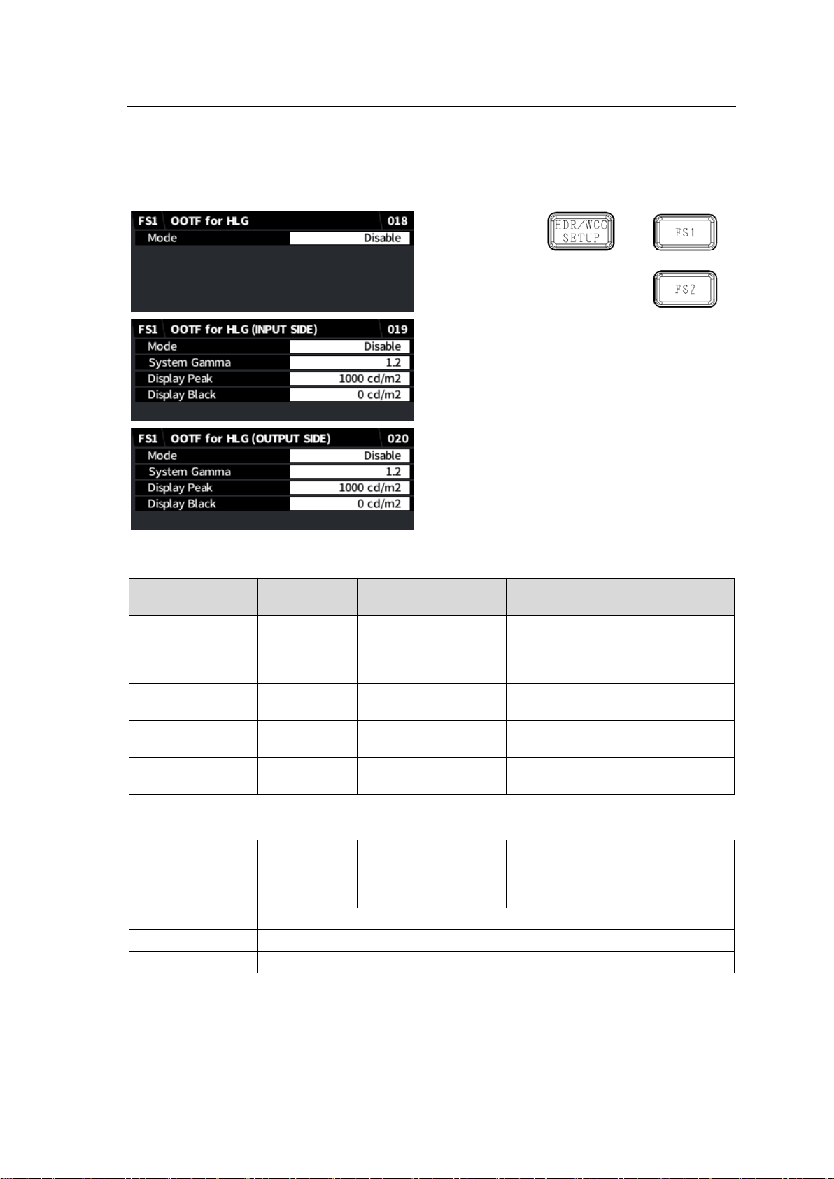
5-5. OOTF for HLG (FA-96AHDR)
Item
Default
Setting range
(Steps)
Description
Mode
Disable
Disable
OOTF
Selecting OOTF converts signals
from HLG to other gamma curve.
Selects the gamma and luminance
peaks below.
System Gamma
1.2
1.0 - 2.0
(0.1)
Sets the gamma value.
Display Peak
1,000 cd/m2
100 - 10,000 cd/m2
(100 cd/m2)
Sets the maximum luminance
peak for Display Light.
Display Black
0 cd/m2
0 - 100 cd/m2
(10 cd/m2)
Sets the minimum luminance peak
for Display Light.
Mode
Disable
Disable
Inverse OOTF
Selecting Inverse OOTF converts
signals to HLG from other gamma
curve. Selects the gamma and
luminance peaks below.
System Gamma
(Same as above)
Display Peak
(Same as above)
Display Black
(Same as above)
OOTF menus are effective only when HLG BT.2100 is selected under Input / Output Gamma
Curve. Set Mode to Disable in other cases.
If Enable is selected for Mode (in the OOTF for HLG menu), set OOTF settings in the OOTF for Y
GAMMA (INPUT SIDE) or OOTF for Y GAMMA (OUTPUT SIDE) menu (FA-96AHDR required).
OOTF for HLG (INPUT SIDE)
OOTF for HLG (OUTPUT SIDE)
27
Page 28
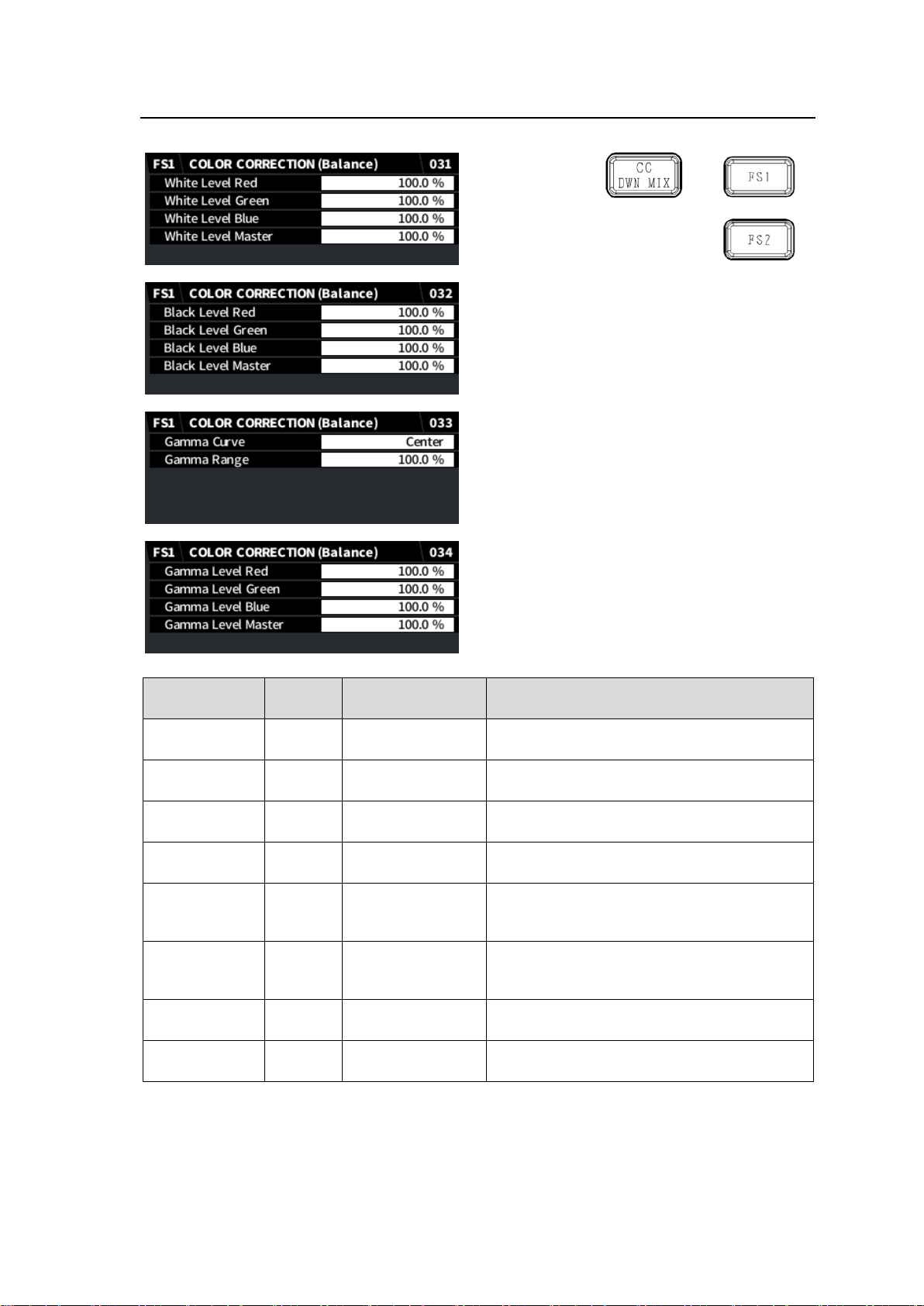
5-6. COLOR CORRECTION (Balance)
Item
Default
Setting range
(Steps)
Description
White Level
(RGB)
100.0%
0.0 - 200.0%
(0.5%)
Sets the white level by separately adjusting R,
G, and B components.
White Level
Master
100.0 %
0.0 - 200.0%
(0.5%)
Sets the white level by simultaneously
adjusting R, G, and B components.
Black Level
(RGB)
100.0%
0.0 - 200.0%
(0.5%)
Sets the black level by separately adjusting R,
G, and B components.
Black Level
Master
100.0 %
0.0 - 200.0%
(0.5%)
Sets the black level by simultaneously
adjusting R, G, and B components.
Gamma Curve
Center
Center
Black
White
Selects a gamma curve type.
Gamma Range
100.0%
0.5% - 100.0%
(0.5%)
Sets the upper threshold where the gamma
correction is enabled. A 100% value is based
on the OETF Maximum Input.
Gamma Level
(RGB)
100.0%
0.0 - 200.0%
(0.5%)
Sets the gamma level by separately adjusting
R, G, and B components.
Gamma Level
Master
100.0 %
0.0 - 200.0%
(0.5%)
Sets the gamma level by simultaneously
adjusting R, G, and B components.
If Color Correction Mode is set to Balance (RGB):
28
Page 29
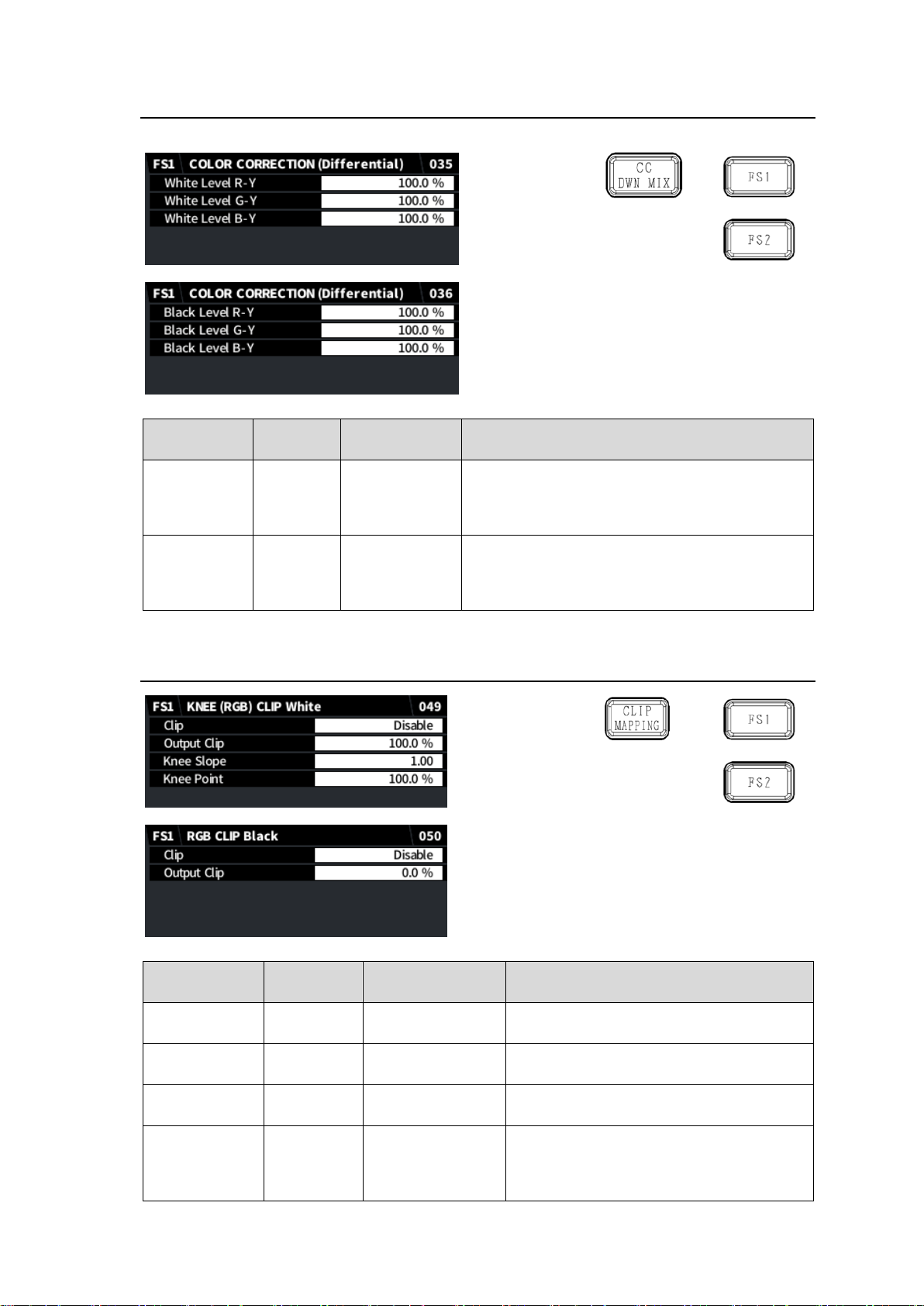
5-7. COLOR CORRECTION (Differential)
Item
Default
Setting range
(Steps)
Description
White Level
(R-Y)
(G-Y)
(B-Y)
100.0%
0.0 - 200.0%
(0.5%)
Sets the white level by separately adjusting R-Y,
G-Y and B-Y components.
Black Level
(R-Y)
(G-Y)
(B-Y)
100.0%
0.0 - 200.0%
(0.5%)
Sets the black level by separately adjusting R-Y,
G-Y and B-Y components.
Item
Default
Setting range
(Steps)
Description
Clip
Disable
Disable
Enable
Enables/disables KNEE CLIP (WHITE).
Output Clip
100.0 %
50.0 - 150.0 %
(0.5 %)
Sets the upper clip point in RGB color
space.
Knee Slope
1.00
0.1 - 1.0
(0.05)
Sets slope of knee clip in high luminance
areas.
Knee Point
100.0 %
50.0 - 150.0 %
(0.5 %)
Sets the knee clip start point in the high
luminance areas. Maximum and default
values vary depending on the White Level
(RGB white clip) setting.
If Color Correction Mode is set to Differential:
5-8. KNEE (RGB) CLIP (White/Black)
KNEE (RGB) CLIP White
29
Page 30
KNEE CLIP Black
Clip
Disable
Disable
Enable
Enables/disables Knee CLIP (BLACK).
Output Clip
0.0 %
-50.0 to 50.0 %
(0.1 %)
Sets the lower clip point in RGB color
space.
Item
Default
Setting range
(Steps)
Description
Clip
Disable
Disable
Enable
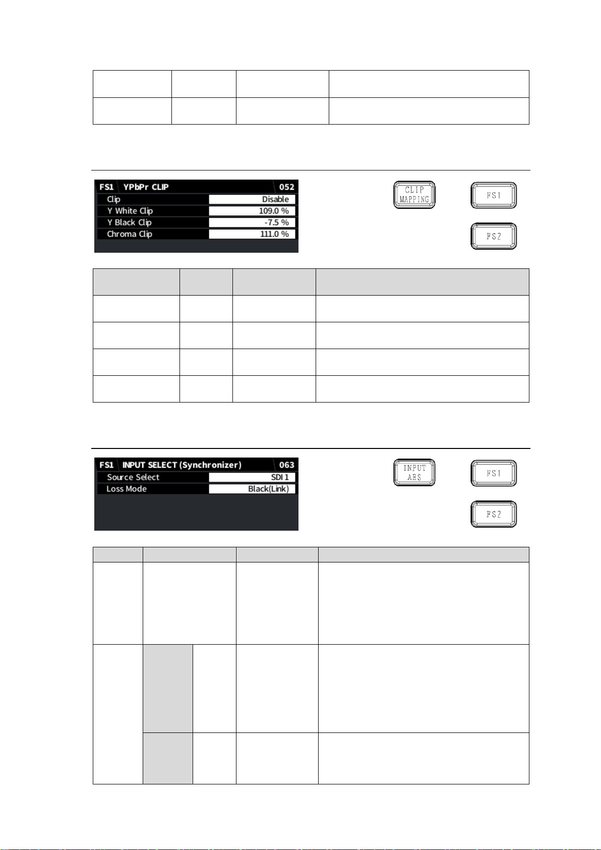
Enables/disables YPbPr CLIP.
Y White Clip
109.0%
50.0 to 109.0 %
(0.5 %)
Sets the upper Y signal limit.
Y Black Clip
-7.5%
-7.5 to 50.0 %
(0.5 %)
Sets the lower Y signal limit.
Chroma Clip
111.0%
50.0 to 111.0 %
(0.5 %)
Sets the upper and lower PbPr signal limits.
Item
Default
Setting range
Description
Source
Select
SDI1 (FS1)
SDI2 (FS2)
SDI 1
SDI 2
Slot-A 1
Slot-A 2
Slot-A 3
Slot-A 4
Slot-A 1-4
Selects a video signal input to FS1 or FS2.
* Slot-A 1 to Slot-A 14 are available when
FA-96EX3G44-R is installed into Slot A.
* Slot-A 1-4 is available only on FS1.
Loss
Mode
W/o
FA-964K
Black
Black
Auto Freeze
Output Mute
Selects the output mode for input signal loss.
Black: Outputs a black video.
Auto Freeze: Freezes and outputs the last
normal video.
Output Mute: Outputs no video signal so that
the FA-9600 downstream device can
detect video loss.
W/
FA-964K
Black
(Link)
Black(Link)
Black(Separate)
Auto Freeze
Output Mute
Black(Link): Outputs a black video.
Black(Separate): Output the input video
displaying black for the lost part. See <p
31> for partial loss of 4K Quad input.
5-9. YPbPr CLIP
5-10. INPUT SELECT (Synchronizer)
30
Page 31
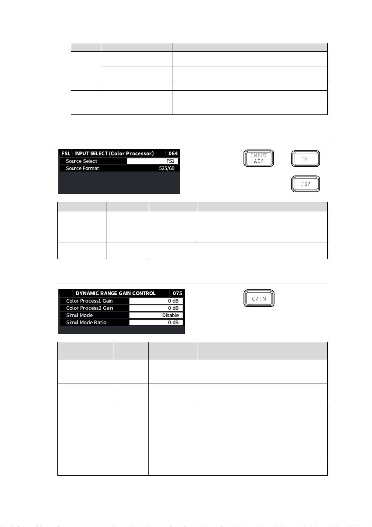
* Loss Mode: When a part of 4K video signal (Quad Link 3G) is lost:
4K input
Loss Mode setting
Output image when a part of image is lost
2-Sample
Interleave
Black(Link), Output Mute
Compensates the loss and restores the whole input image,
maintaining its appearance.
Black(Separate)
Replaces lost parts with black to restore the whole input
image. The image is displayed with lower luminance.
Auto Freeze
Freezes and outputs the last normal video.
Square
Black(Link)
Outputs a black video.
Black(Separate),
Auto Freeze, Output Mute
Outputs the input video displaying black for the lost part.
Item
Default
Setting range
Description
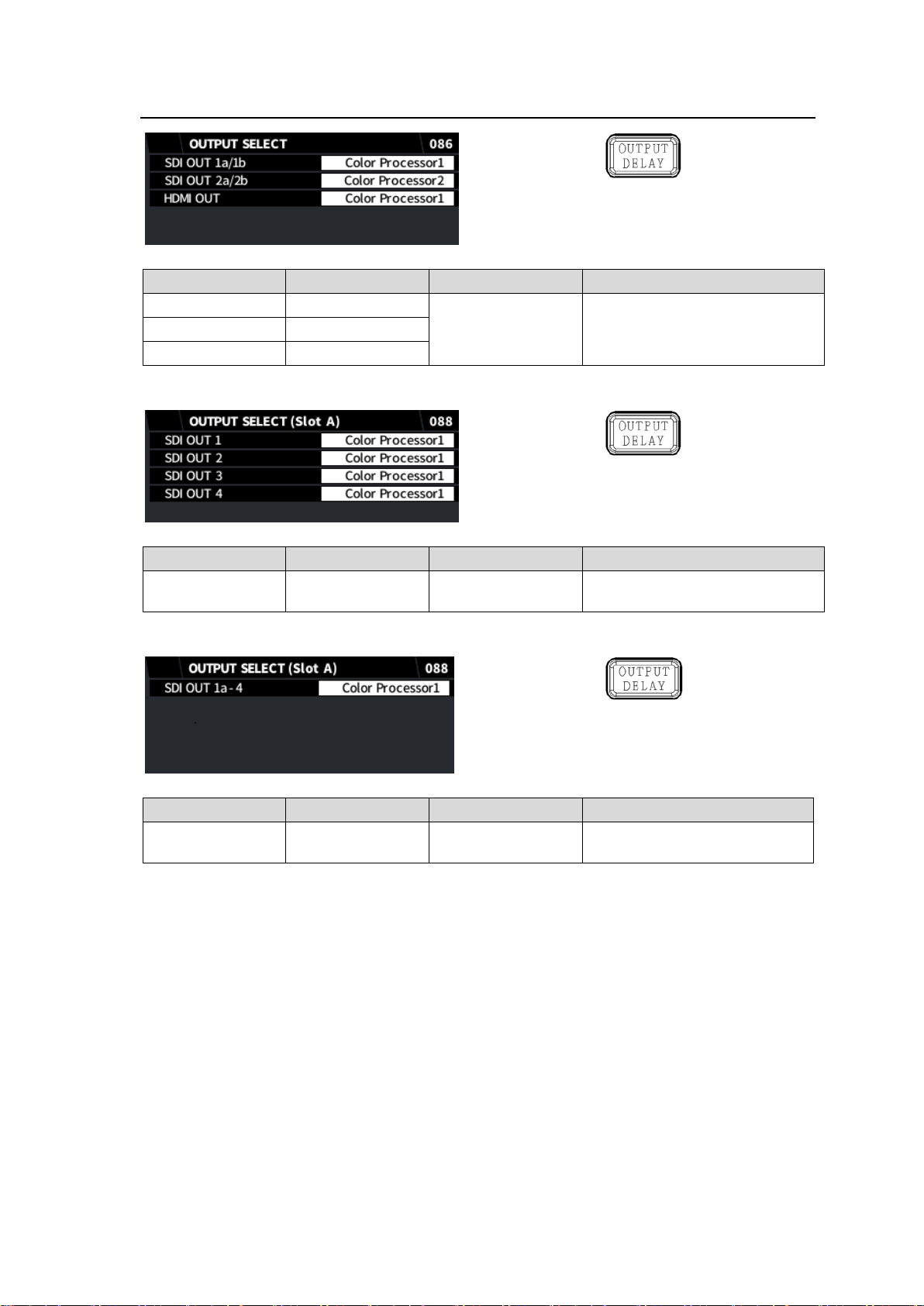
Source Select
FS1
FS1
Converter 1
FS2
Converter 2
Selects a source signal for FS1 or FS2 Color
Processor.
Source Format
-
-
Displays the signal format selected under
Source Select.
Item
Default
Setting range
(Steps)
Description
Color Process1
Gain
0 dB
-42dB to 42dB
(1dB)
Sets the gain for linear RGB signal values
that are EOTF-processed on Color Processor
1.
Color Process2
Gain
0 dB
-42dB to 42dB
(1dB)
Sets the gain for linear RGB signal values
that are EOTF-processed on Color Processor
2.
Simul Mode
Disable
Disable
Enable
Sets whether to keep the gain difference
between Color Processor 1 and 2.
Setting to Enable allows you to set Gain,
Color Correction (Differential, Balance)
and Clip (RGB Clip, YPbPr Clip)
parameters by preserving the gain difference
set under Simul Mode Ratio below.
Simul Mode Ratio
0 dB
-24 dB to 24 dB
(1 dB)
Sets the gain difference between Color
Processor 1 and 2. (Processor 1 base)
5-11. INPUT SELECT (Color Processor)
5-12. DYNAMIC RANGE GAIN CONTROL
31
Page 32
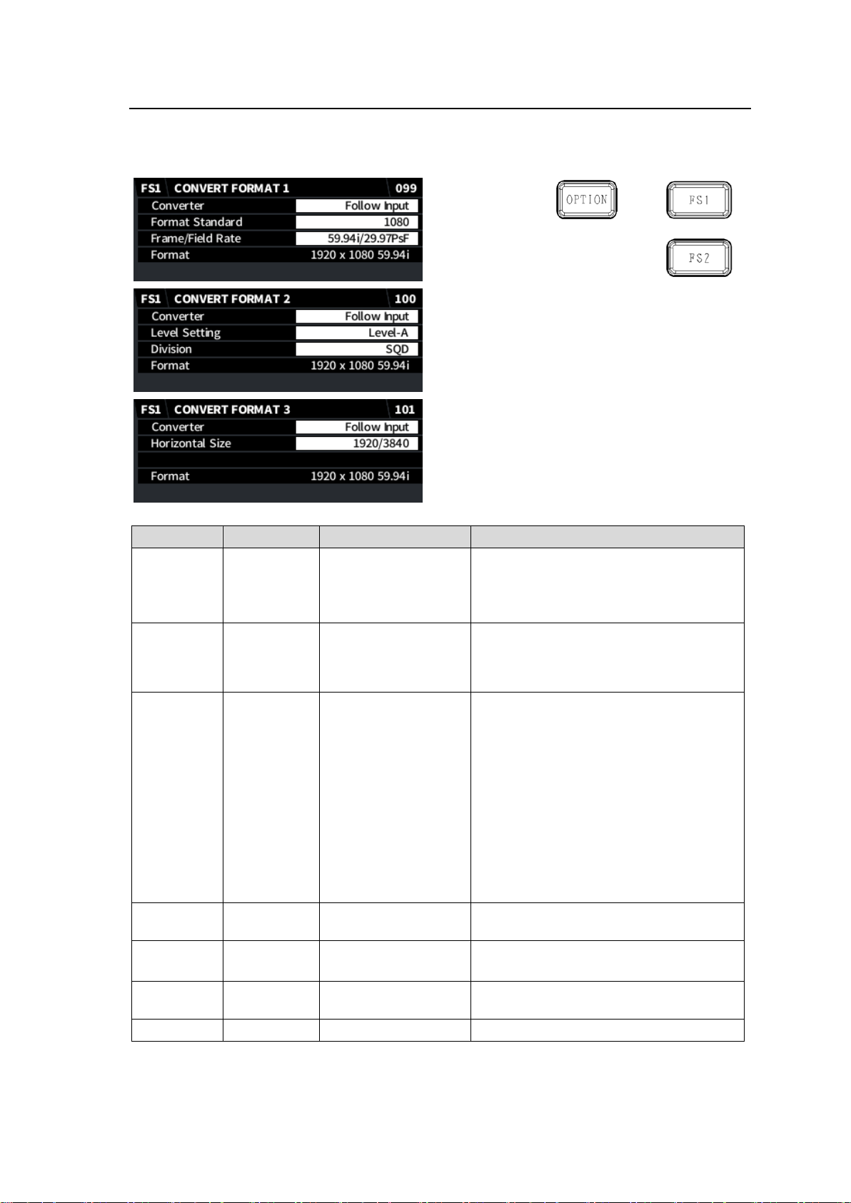
5-13. OUTPUT SELECT
Item
Default
Setting range
Description
SDI OUT 1a/1b
Color Processor1
Color Processor1
Color Processor2
Selects video signal output.
SDI OUT 2a/2b
Color Processor2
HDMI OUT
Color Processor1
Item
Default
Setting range
Description
SDI OUT 1 to 4
Color Processor1
Color Processor1
Color Processor2
Selects a video signal for each
output.
Item
Default
Setting range
Description
SDI OUT 1a - 4
Color Processor1
Color Processor1
Color Processor2
Selects a video signal for all
outputs.
This menu requires FA-96EX3G44-R to be installed into Slot A.
This menu requires FA-96EX12G06 to be installed into Slot A.
32
Page 33

5-13-1. HDMI Output Restrictions
Note that HDMI output cannot display the following format images properly even if they can be
selected under OUTPUT SELECT.
When in standard configuration:
-Black images displayed for 1080/24PsF, 23.98PsF format video signals (respectively output
as 1080/24p, 23.98p output).
-The following format video signals are output unsynchronized.
1080/60p, 59.94p, 50p(3G-SDI Level-B only)
720/30p, 29.97p, 25p, 24p, 23.98p
When FA-964K is configured:
-Black images displayed for 3840 x 2160/60p, 59.94p, 50p (3G-SDI Level-A, SQD only)
-The following format video signals are output unsynchronized.
3840 x 2160/60p, 59.94p, 50p (3G-SDI Level-B, SQD/2SI)
33
Page 34
5-14. CONVERTER FORMAT (FA-96UDC)
Item
Default
Setting range
Description
Converter
Follow Input
Follow Input
Manual
Specifies the converter output format.
Follow Input: Converter input signal
format
Manual: Signal format specified below.
Format
Standard
1080
SD
720
1080
2160
Specifies the output format after
conversion. (2160 available only on FS1
and FA-964K required)
Frame/Field
Rate
59.94i/
29.97PsF
60p
59.94p
50p
30p
29.97p
25p
24p
23.98p
60i/30PsF
59.94i/29.97PsF
50i/25PsF
24PsF
23.98PsF
Specifies the frame/field rate.
Level
Setting
Level-A
Level-A
Level-B (Dual Link)
Selects the SDI mapping level.
Division
(FA-964K)
SQD
SQD
2SI
Selects the SDI image division method.
(FS1 only, FA-964K required)
Horizontal
Size
1920/3840
1920/3840
Displays the horizontal image resolution.
(Display only)
Format - -
Displays the converter output format.
This menu requires FA-96UDC to be installed.
* See Sec. 5-14-1 “Available Conversions on Converter 1 (FS1)” and Sec. 5-14-2 “Available
Conversions on Converter 2 (FS2)” for more details.
34
Page 35
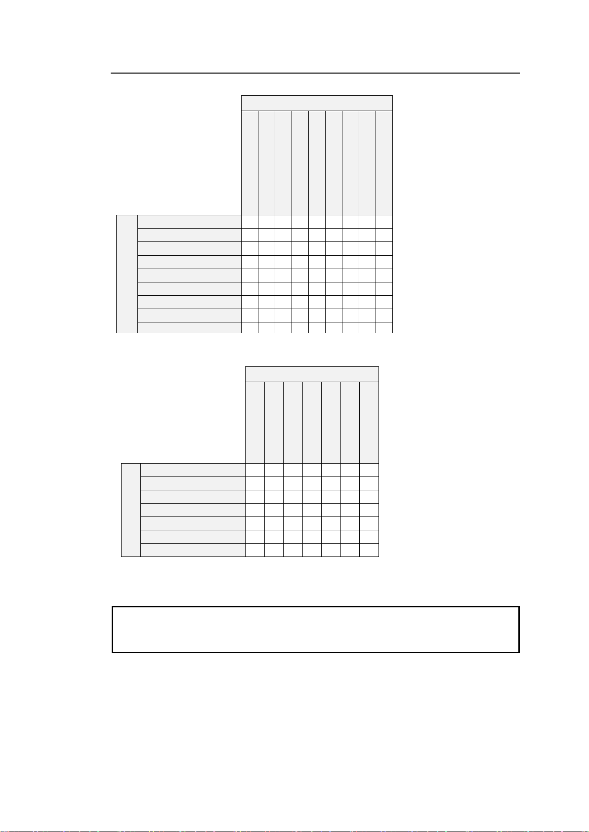
5-14-1. Available Conversions on Converter 1 (FS1)
IMPORTANT
Black video is output when any signal that is not listed in the above tables is specified
for converter input or output.
Conversions between 59.94 and 50 Hz family signals are not supported.
✔: Available conversion
Output
2160/59.94p
(
*
)
1080/59.94p(A) 1080/59.94p(
B)
1080/29.97p 1080/23.98p 1080/59.94i(29.97PsF) 1080/23.98PsF 720/59.94p 525/60(SD
-SDI)
Input
2160/59.94p (*)
✔ ✔ ✔
✔ ✔ ✔
✔
1080/59.94p(A)
✔ ✔ ✔
✔ ✔ ✔
✔
1080/59.94p(B)
✔ ✔ ✔
✔ ✔ ✔
✔
1080/29.97p
✔ ✔ ✔
✔ ✔ ✔
✔
1080/23.98p
✔ ✔
1080/59.94i(29.97PsF)
✔ ✔ ✔
✔ ✔ ✔
✔
1080/23.98PsF
✔ ✔
720/59.94p
✔ ✔ ✔
✔ ✔ ✔
✔
525/60(SD-SDI)
✔ ✔ ✔
✔ ✔ ✔
✔
✔: Available conversion
Output
2160/50p
(
*
)
1080/50p(A) 1080/50p(
B)
1080/2
5p
1080/5
0i(25PsF)
720/
50p
625/50(SD
-SDI)
Input
2160/50p (*)
✔ ✔ ✔ ✔ ✔ ✔ ✔
1080/50p(A)
✔ ✔ ✔ ✔ ✔ ✔ ✔
1080/50p(B)
✔ ✔ ✔ ✔ ✔ ✔ ✔
1080/25p
✔ ✔ ✔ ✔ ✔ ✔ ✔
1080/50i(25PsF)
✔ ✔ ✔ ✔ ✔ ✔ ✔
720/50p
✔ ✔ ✔ ✔ ✔ ✔ ✔
625/50(SD-SDI)
✔ ✔ ✔ ✔ ✔ ✔ ✔
<59.94 Hz family>
<50 Hz family>
(*) FA-964K option required for conversions (including 3G-SDI Level-A/B and SQD/2SI)
35
Page 36
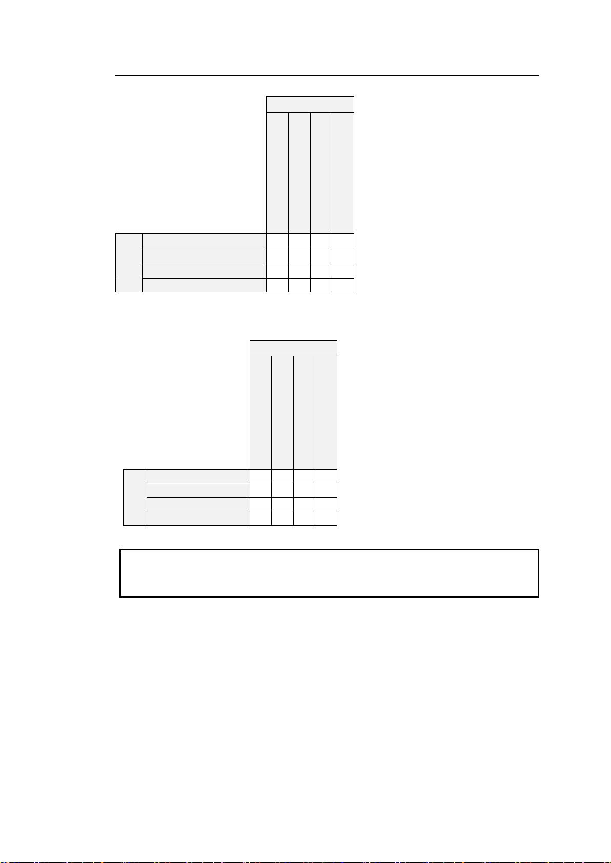
5-14-2. Available Conversions on Converter 2 (FS2)
IMPORTANT
Black video is output when any signal that is not listed in the above tables is specified
for converter input or output.
Conversions between 59.94 and 50 Hz family signals are not supported.
✔: Available conversion
Output
1080/59.94p(A) 1080/59.94p(
B)
1080/29.97p 1080/59.94i(29.97PsF)
Input
1080/59.94p(A)
✔ ✔ ✔
✔
1080/59.94p(B)
✔ ✔ ✔
✔
1080/29.97p
✔ ✔ ✔
✔
1080/59.94i(29.97PsF)
✔ ✔ ✔
✔
✔: Available conversion
Output
1080/50p(A) 1080/50p(
B)
1080/2
5p
1080/5
0i(25PsF)
Input
1080/50p(A)
✔ ✔ ✔
✔
1080/50p(B)
✔ ✔ ✔
✔
1080/25p
✔ ✔ ✔
✔
1080/50i(25PsF)
✔ ✔ ✔
✔
<59.94 Hz family>
<50 Hz family>
36
Page 37
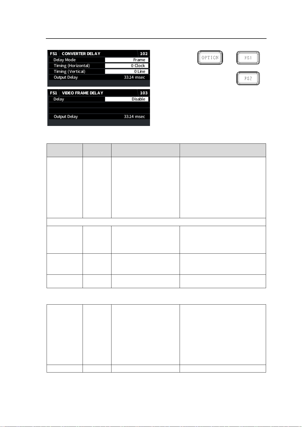
5-15. CONVERTER / VIDEO FRAME DELAY (FA-96UDC)
Item
Default
Setting range
(Steps)
Description
Delay Mode
Frame
Frame
Minimum
Adjustable
Selects the Conversion 1 or 2 output
timing (delay amount).
Frame: Outputs at the same timing
(delayed in frames) as that of
the FS.
Minimum: Outputs with the
minimum delay.
Adjustable: Outputs at the timing
adjusted by the following
parameters.
If Delay Mode is set to Adjustable, use the following parameters to adjust the output timing.
Timing
(Horizontal)
0 Clock
-2750 to 2750Clock (2160)
-1375 to 1375Clock (1080)
-2063 to 2063Clock (720)
-864 to 864Clock (SD)
Adjusts the horizontal timing.
Timing
(Vertical)
0 Line
-563 to 563Line (1080)
-375 to 375Line (720)
-313 to 313Line (SD)
Adjusts the vertical timing.
Output Delay - -
Displays the converter total delay
time.
Delay
Disable
Disable
0.5 - 8.0 Frames
(0.5 Frames)
Allows you to add a delay in 0.5
frame increments to the converter
output.
As for 3G-Level B, 1080i and SD
output signals, delays can be added
in 0.5 frame increments for
progressive signal input and aspect
ratio conversions, or in 1 frame
increments in other cases.
Output Delay - -
(Same as above)
This menu requires FA-96UDC to be installed.
CONVERTER DELAY
VIDEO FRAME DELAY (FA-96UDC)
37
Page 38
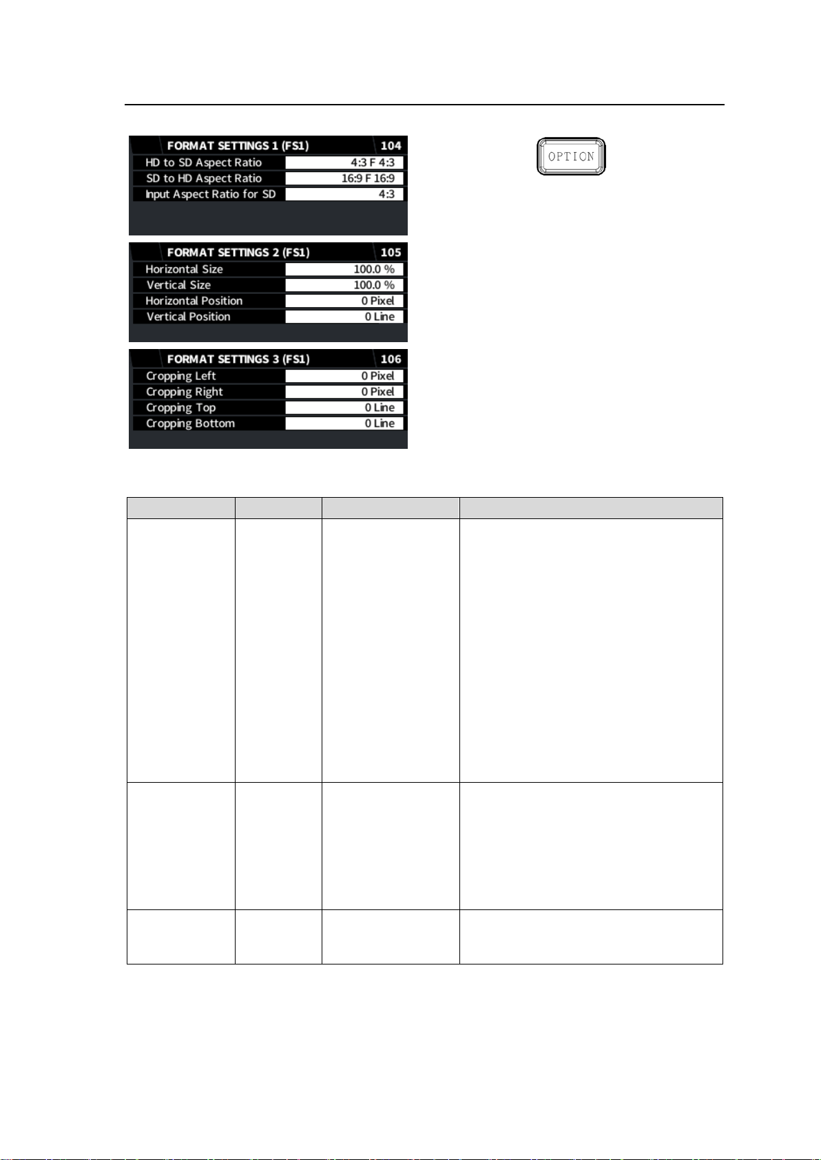
5-16. FORMAT SETTING 1, 2, 3 (FS1) (FA-96UDC)
Item
Default
Setting range
Description
HD to SD
Aspect Ratio
4:3 F 4:3
4:3 L 16:9 T
4:3 L 14:9 T
4:3 L>16:9
4:3 F 4:3
4:3 L 16:9 PRTD
4:3 L 14:9
4:3 F ALT 14:9
4:3 L ALT 14:9
4:3 L ALT 4:3
16:9 L>16:9
16:9 F 16:9
16:9 P 4:3
16:9 F PRTD
16:9 P 14:9
16:9 P ALT 14:9
16:9 F ALT 14:9
16:9 F ALT 4:3
Specifies the aspect ratio when
converting HD-SDI to SD-SDI signals.
SD to HD
Aspect Ratio
16:9 F 16:9
16:9 L>16:9
16:9 F 16:9
16:9 P 4:3
16:9 F PRTD
16:9 P 14:9
16:9 P ALT 14:9
16:9 F ALT 14:9
16:9 F ALT 4:3
Specifies the aspect ratio when
converting SD-SDI to HD-SDI signals.
Input Aspect
Ratio for SD
4:3
4:3
16:9
Selects the SD input aspect ratio.
If the input image is horizontally
squeezed, set to 16:9.
These menus (available only on FS1) require FA-96UDC to be installed.
FORMAT SETTING 1
38
Page 39
FORMAT SETTING 2
Item
Default
Setting range
(Steps)
Description
Horizontal Size
100.0%
50.0% to 150.0%
(0.1%)
Selects the horizontal image size
ratio after conversion.
Vertical Size
100.0%
50.0% to 150.0%
(0.1%)
Selects the vertical image size ratio
after conversion.
Horizontal
Position
0 Pixel
See the table below.
(2 Pixel)
Selects the horizontal image
position after conversion.
Vertical Position
0 Line
See the table below.
(1 Line)
Selects the vertical image position
after conversion.
Cropping Left
0 Pixel
See the table below.
(2 Pixel)
Crops the image from the left side.
Cropping Right
0 Pixel
Crops the image from the right side.
Cropping Top
0 Line
See the table below.
(1 Line)
Crops the image from the top.
Cropping Bottom
0 Line
Crops the image from the bottom.
Video signal
Horizontal
Position
Vertical Position
Cropping Left
Cropping Right
Cropping Top
Cropping Bottom
2160p
-1920 to 1920
-1080 to 1080
0-1918
0-1079
1080i/p
-960 to 960
-540 to 540
0-958
0-539
720p
-640 to 640
-360 to 360
0-638
0-359
525i (NTSC)
-360 to 360
-244 to 244
0-358
0-243
625i (PAL)
-360 to 360
-288 to 288
0-358
0-287
Item
Default
Setting range
Description
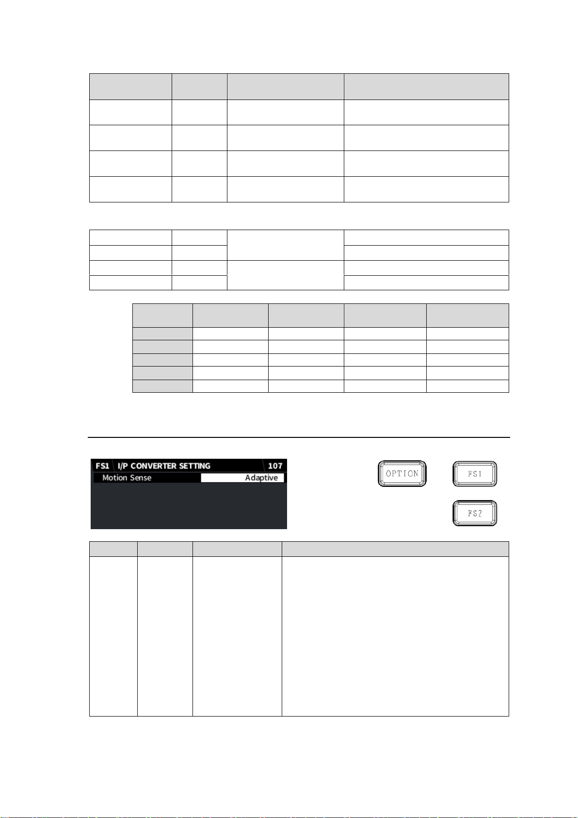
Motion
Sense
Adaptive
Field
Adaptive
Frame(ODD 1st)
Frame(EVEN 1st)
Field: Generates a progressive image from one
field of an interlaced image. The created
image has no motion artifacts, but vertical
resolution will be reduced.
Adaptive: Detects whether there is motion or no
motion in the scene, and generates an optimal
progressive image.
Frame(ODD 1st): Generates a progressive image
from two fields (odd and even) of an interlaced
image. Suitable for progressive segmented
frame input shot in progressive format.
Frame(EVEN 1st): Generates a progressive
image from two fields (even and odd) of and
interlaced image.
FORMAT SETTING 3
5-17. I/P CONVERTER SETTING (FA-96UDC)
The menu requires FA-96UDC option.
39
Page 40
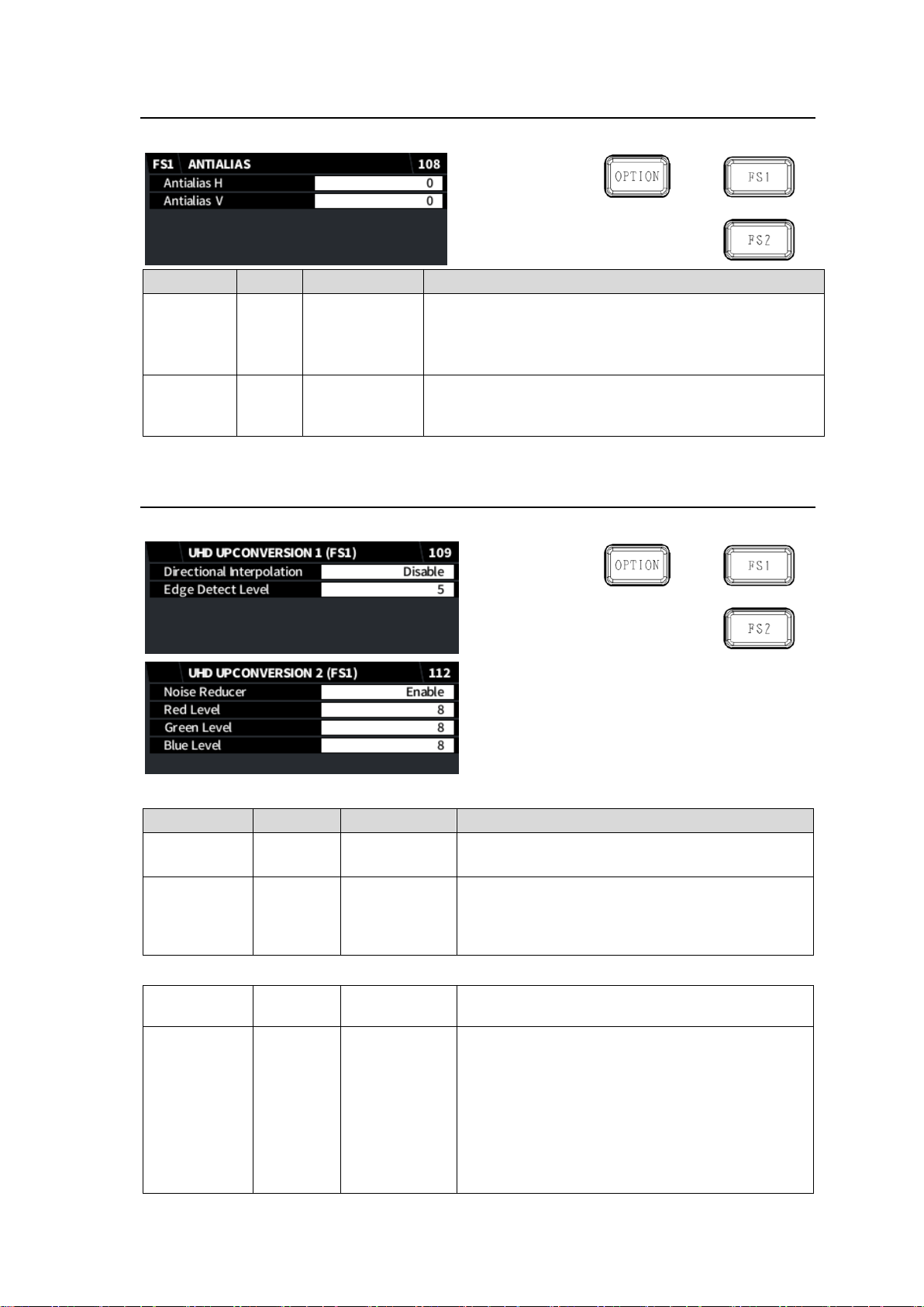
5-18. ANTIALIAS (FS1) (FA-96UDC)
Item
Default
Setting range
Description
Antialias H
0
Off
-7 to +8
Sets the horizontal anti-aliasing for the output video
image.
-7 to +8 (weak to strong)
Set to Off if no anti-aliasing is applied.
Antialias V
0
Off
-7 to +8
Sets the vertical anti-aliasing for the output video image.
-7 to +8 (weak to strong)
Set to Off if no anti-aliasing is applied.
Item
Default
Setting range
Description
Directional
Interpolation
Enable
Disable
Enable
Enables/disables Edge Detect Level setting.
Effective only for 4K up-conversions.
Edge Detect
Level
5
0 - 10
Sets Edge Detect Level.
The lower the value, the higher the detection
sensitivity, increasing the directional interpolation
area.
Noise
Reducer
Enable
Disable
Enable
Enables/disables Noise Reducer applied for 4K
up-conversions.
Red Level
Green Level
Blue Level
8
1-16
Sets the noise reduction level for low luminance
side (darker areas) in RGB. Effective for camera
lower random noises.
Ineffective for noises in high luminance side
(brighter areas) or block noises from compression.
The stronger (higher) the Red, Green, Blue or
Filter level, the fewer the high-frequency
components in video images.
The menu (FS1 only) requires FA-96UDC option.
5-19. UHD UPCONVERSION 1, 2 (FS1) (FA-96UDC/964K)
The menu (FS1 only) requires FA-964K and FA-96UDC options.
UHD UPCONVERSION 1
UHD UPCONVERSION 2
40
Page 41
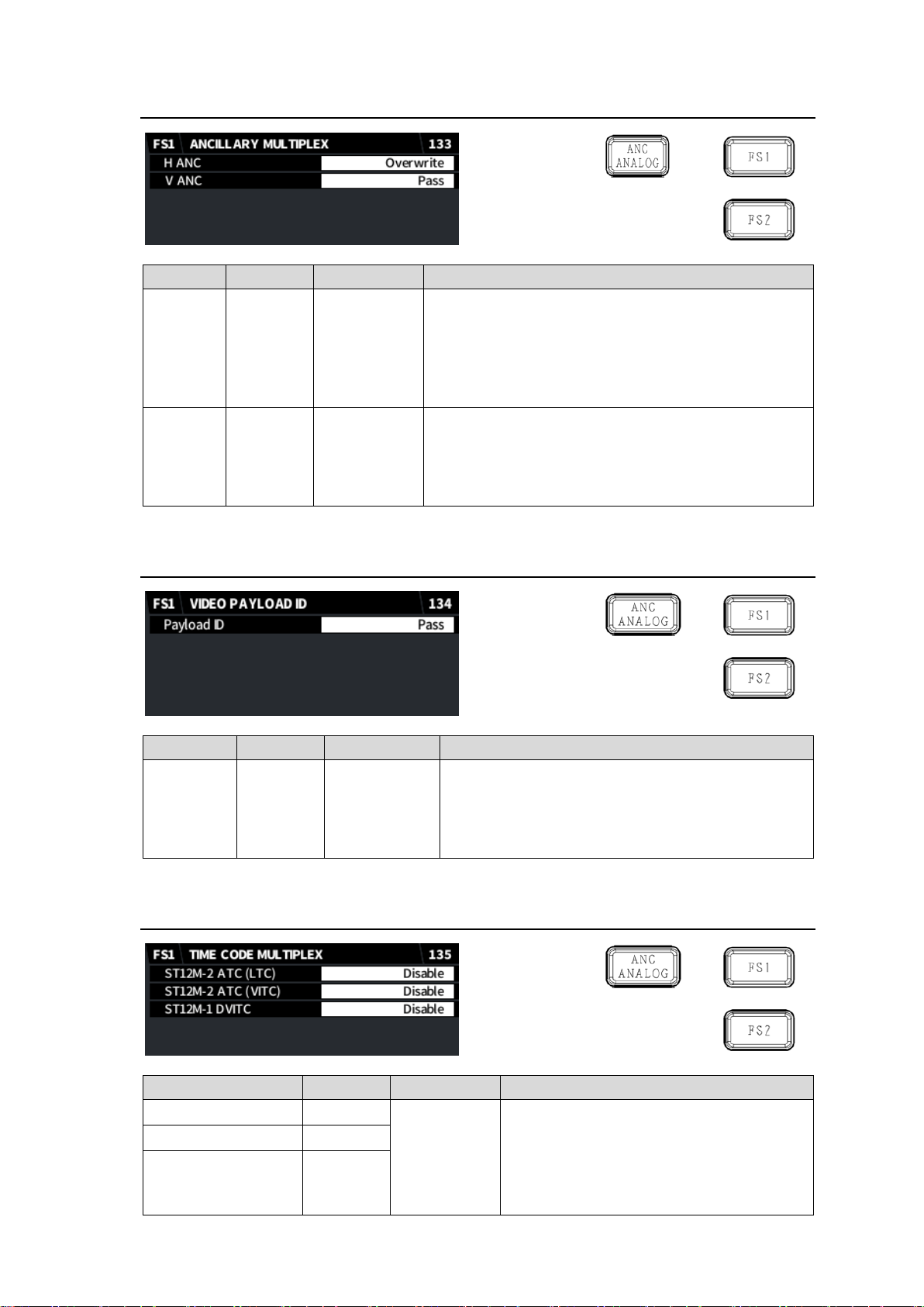
5-20. ANCILLARY MULTIPLEX
Item
Default
Setting range
Description
H ANC
Overwrite
Overwrite
Pass
Blank
Selects the H ANC data insertion mode to each FS
output.
Overwrite: Inserts the internally-processed input H
ANC data.
Pass: Inserts the input H ANC data without processing.
Blank: Embeds no input signal H ANC data.
V ANC
Pass
Pass
Blank
Selects the V ANC data insertion mode to each FS
output.
Pass: Inserts the input V ANC data without
processing.
Blank: Embeds no V ANC data.
Item
Default
Setting range
Description
Payload ID
Overwrite
Pass
Overwrite
Selects the Payload ID insertion mode.
Pass: Inserts input payload ID codes without
change.
Overwrite: Inserts internally-generated payload ID
codes.
Item
Default
Setting range
Description
ST12M-2 ATC(LTC)
Disable
Disable
Enable
Selects whether to embed timecode into
each FS output.
Disable: Embeds no timecode.
Enable: Embeds timecode. Generate a
timecode using following timecode
menus.
ST12M-2 ATC(VITC)
Disable
ST12M-1 DVITC
Disable
5-21. VIDEO PAYLOAD ID
5-22. TIME CODE MULTIPLEX
41
Page 42
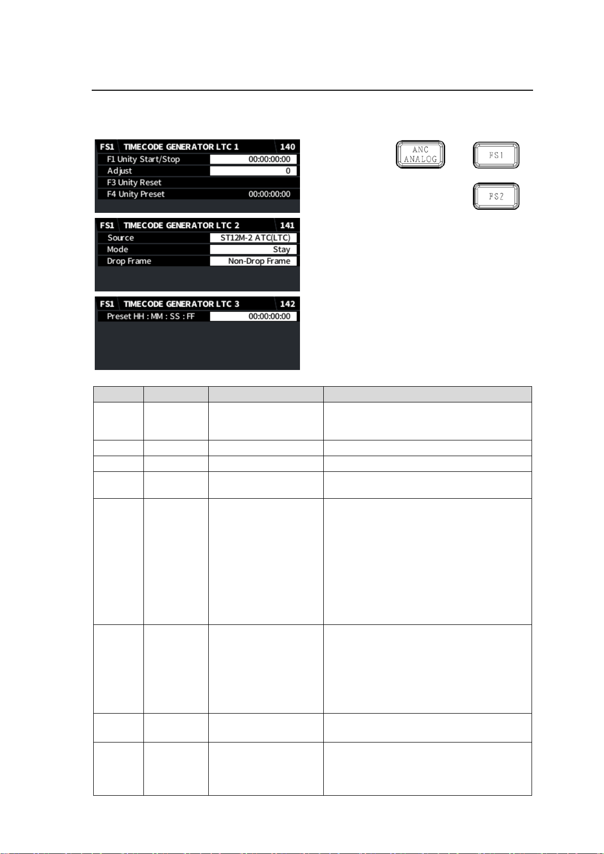
Item
Default
Setting range
Description
Start/
Stop
-
-
Pressing F1 Unity button starts the
timecode. Re-pressing the button stops the
timecode.
Adjust 0 -16 to +16
Sets the offset from the source timecode.
-
-
-
Pressing F3 Unity resets the timecode.
-
-
-
Pressing F4 Unity sets the timecode to the
preset value.
Source
ST12M-2
ATC(LTC)
ST12M-2 ATC(LTC)
ST12M-2 ATC(VITC)
ST12M-1 VITC(DVITC)
ST12M-1 LTC IN
Generator
Selects the timecode source.
ST12M-2 ATC(LTC): ATC(LTC) timecode in
the SDI input
ST12M-2 ATC(VITC): ATC(VITC) timecode
in the SDI input
ST12M-1 VITC(DVITC): VITC(DVITC)
timecode in the SD-SDI input
ST12M-1 LTC IN: LTC input (FA-96DIN4-
-CBL required)
Generator: Generator’s timecode
Mode
Stay
Stay
Continue
Disable
Selects the way to recover when a timecode
source loss is detected.
Stay: Stays outputting the last timecode.
Continue: Continues running with the timing
before loss.
Disable: Stops timecode output when the
source loss is detected.
Drop
Frame
Non-Drop
Frame
Non-Drop Frame
Drop Frame
Selects drop frame or non-drop frame
timecode.
Preset
HH:MM:
SS: FF
00:00:00:00
00:00:00:00 to
23:59:59:29
Sets the timecode preset value.
Pressing F4 Unity sets this value to the
timecode.
Invalid input values are corrected.
5-23. TIMECODE GENERATOR LTC 1, 2, 3
This menu allows you to generate LTC timecodes. To embed timecode onto FS output, set
ST12M-2 ATC(LTC) to Enable in the TIME CODE MULTIPLEX (135) menu.
42
Page 43
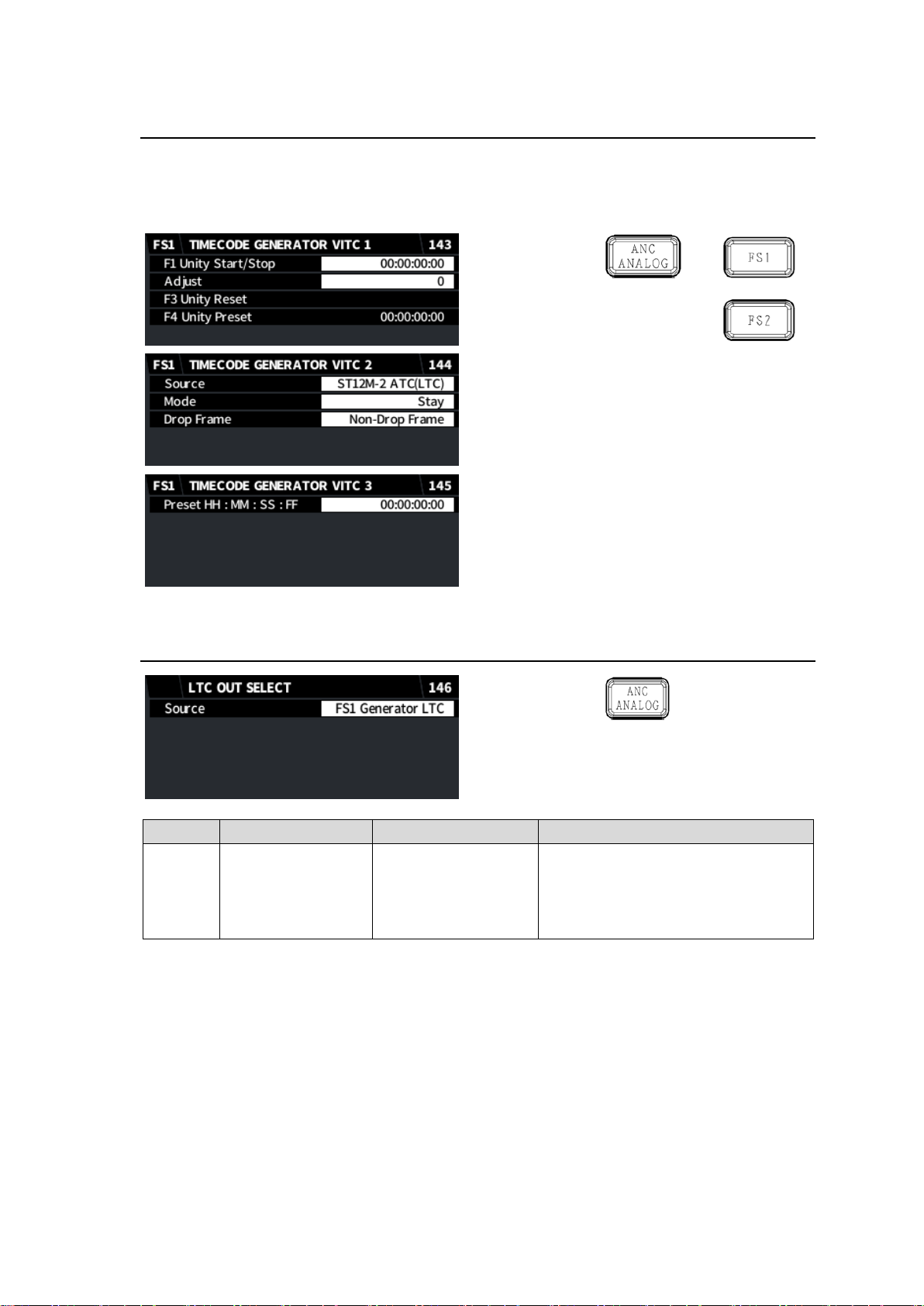
Item
Default
Setting range
Description
Source
FS1 Generator LTC
FS1 Generator LTC
FS2 Generator LTC
The LTC OUT on FA-96DIN4CBL
outputs an internally generated
timecode.
This menu selects which timecode
generator to be used.
5-24. TIMECODE GENERATOR VITC 1, 2, 3
This menu allows you to generate VITC timecodes. To embed timecode onto FS output, set
ST12M-1 VITC(DVITC) to Enable in the TIME CODE MULTIPLEX (135) menu.
See the LTC timecode menus to set the VITC(DVITC) timecode.
5-25. LTC OUT SELECT (FA-96DIN4-CBL)
43
Page 44
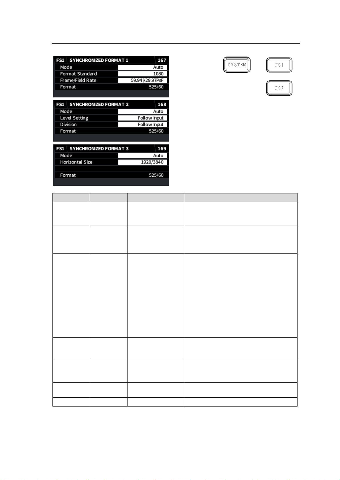
5-26. SYNCHRONIZED FORMAT
Item
Default
Setting range
Description
Mode
Auto
Auto
Manual
Selects the FS output format.
Auto: FS input signal format.
Manual: Signal format specified below
Format
Standard
1080
SD
720
1080
2160
Specifies the vertical image resolution.
(2160 available only on FS1 and FA-964K
required)
Frame/Field
Rate
59.94i/
29.97PsF
60p
59.94p
50p
30p
29.97p
25p
24p
23.98p
60i/30PsF
59.94i/29.97PsF
50i/24PsF
24PsF
23.98PsF
Specifies the frame / field rate.
Level
Setting
Follow Input
Follow Input
Level A
Level B (Dual Link)
Specifies the SDI mapping level.
Division
(FA-964K)
Follow Input
Follow Input
SQD
2SI
Specifies the SDI image division method.
(FS1 only, FA-964K required)
Horizontal
Size
1920/3840
1920/3840
Displays the horizontal image resolution
(Display only)
Format - -
Displays the FS output format.
See Sec. “13-1. “Specifications” for the supported signal formats.
44
Page 45
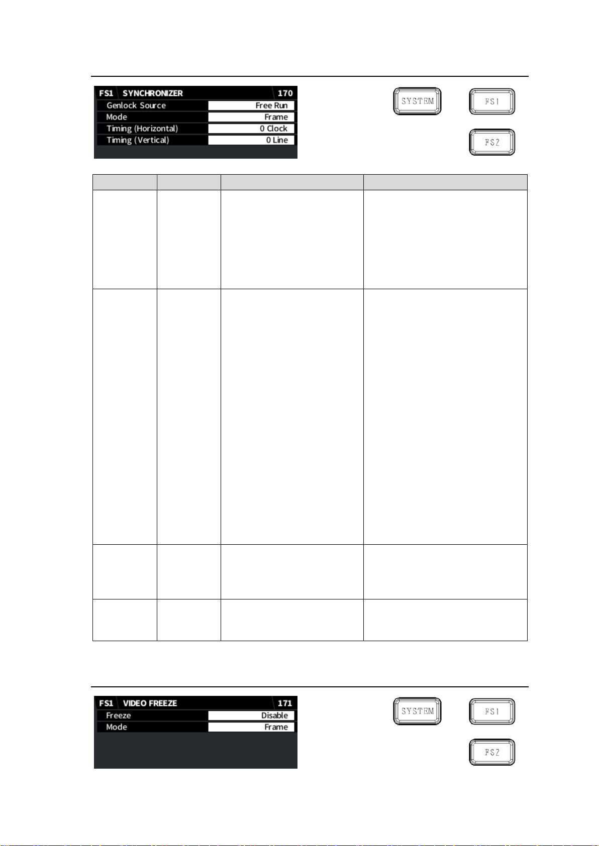
5-27. SYNCHRONIZER
Item
Default
Setting range
Description
Genlock
Source
GENLOCK
IN
GENLOCK IN
FS1
FS2
Free Run
Selects the reference signal.
GENLOCK IN: GENLOCK input
signal
FS 1/2: Input signal selected for
Synchronizer 1 or
Synchronizer 2.
Free Run: Internal reference
signal for both FS1 and FS2
Mode
Frame
Frame
Line
AVDL
Line(Min)
Selects the reference mode.
Frame: Horizontal and vertical
video signal adjustment
referring to genlock signal.
Not necessary for video input
and genlock to sync.
Line: ±1/2H horizontal video
signal adjustment output with
1H delay. Synchronization
necessary for video input and
genlock signal.
AVDL: Horizontal video signal
adjustment output with 1H
delay. Synchronization
necessary for video input and
genlock signal.
Line (Min): ±1/2H horizontal video
signal adjustment output with
minimum delay.
Synchronization necessary
for video input and genlock
signal.
Timing
(Horizontal)
0 Clock
-2750 to 2750 (1080/Level B)
-1375 to 1375 (1080)
-2063 to 2063 (720)
-864 to 864 (SD)
Sets the horizontal offset.
Timing
(Vertical)
0 Line
-563 to 563 (1080)
-375 to 375 (720)
-313 to 313 (SD)
Sets the vertical offset.
5-28. VIDEO FREEZE
45
Page 46
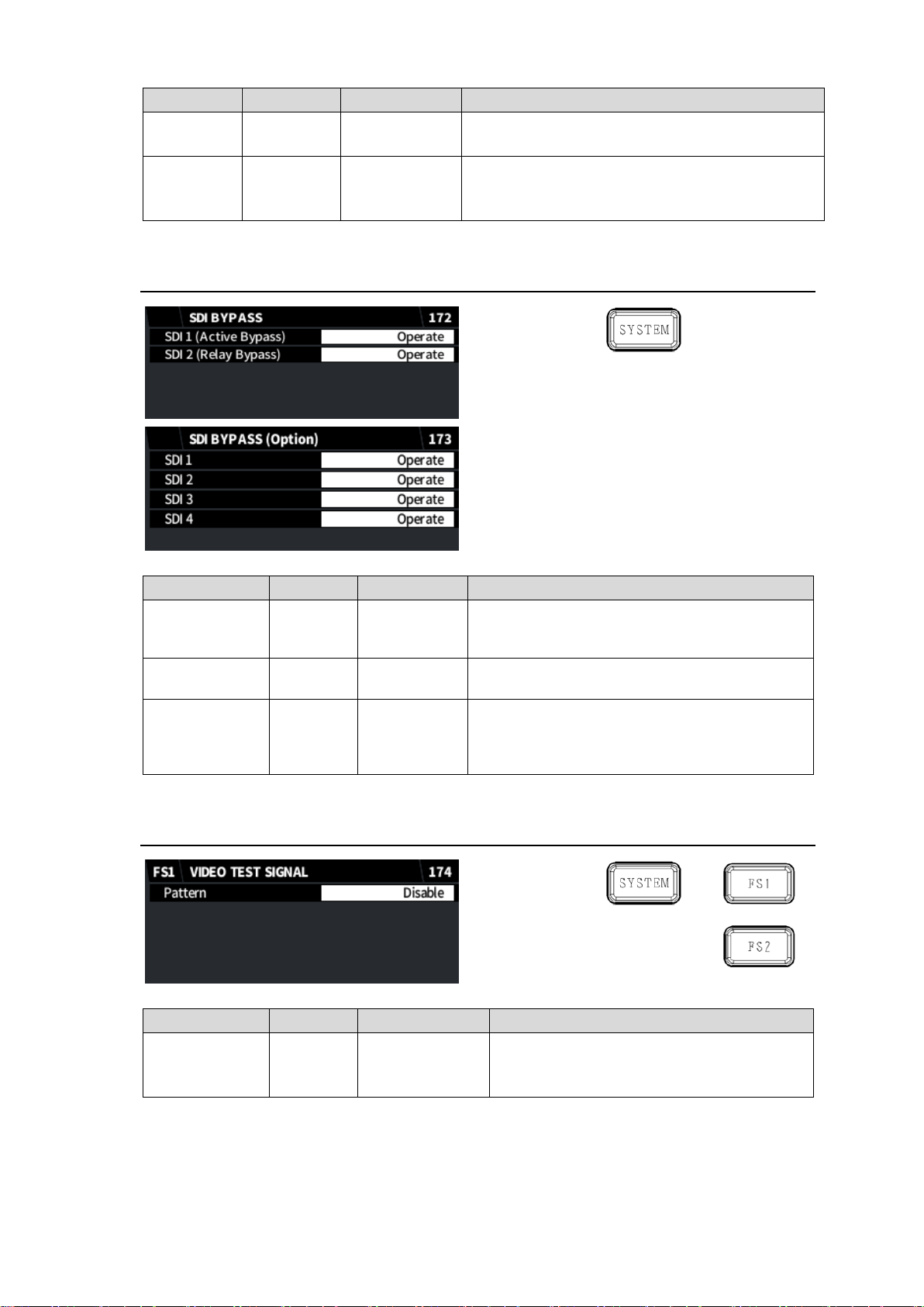
Item
Default
Setting range
Description
Freeze
Disable
Disable
Enable
Turns freeze On/Off.
Mode
Frame
Frame
Odd
Even
Sets the freeze mode.
This setting is ignored if progressive/no signal is
input to FS.
Item
Default
Setting range
Description
SDI 1
(Active Bypass)
Operate
Operate
Bypass
Enables/disables SDI 1 active bypass routing.
Note that Active Bypass is ineffective when unit
power is off.
SDI 2
(Relay Bypass)
Operate
Operate
Bypass
Enables/disables SDI 2 relay bypass routing.
SDI 1
SDI 2
SDI 3
SDI 4
Operate
Operate
Bypass
Enables/disables bypass routing for SDI 1-4 on
FA-96EX3G44-R cards installed into Slot A.
Item
Default
Setting range
Description
Pattern
Disable
Disable
100% Color Bar
75% Color Bar
Outputs the selected test signal.
5-29. SDI BYPASS
5-30. VIDEO TEST SIGNAL
46
Page 47
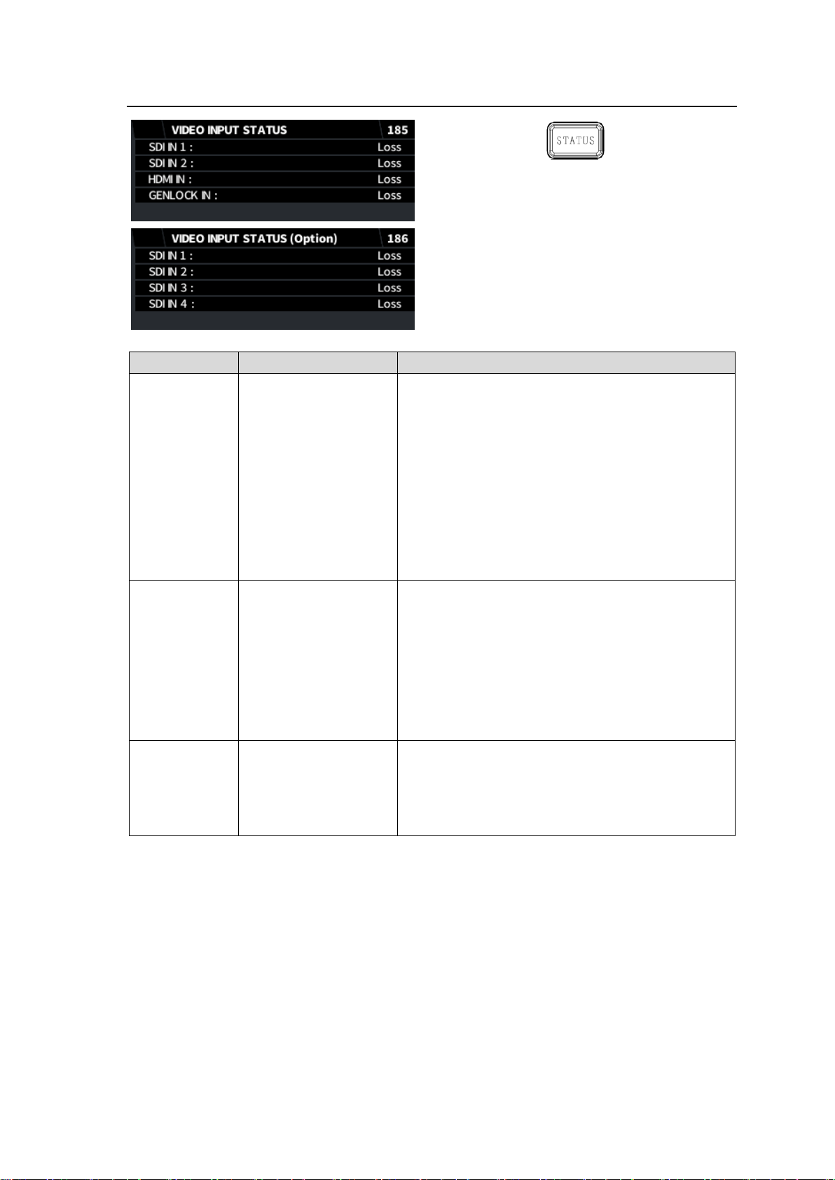
5-31. VIDEO INPUT STATUS
Item
Display
Description
SDI IN 1
SDI IN 2
HDMI IN
Loss
525/60
625/50
1080/59i
1080/50i
720/59p
720/50p
1080/23PsF
1080/24PsF
1080/59p
1080/50p
Bypass
Unknown
Displays each input signal format.
Loss: No input signal
Unknown: Input signal is not supported.
GENLOCK IN
Loss
525/60
625/50
1080/59i
1080/50i
720/59p
720/50p
1080/23PsF
1080/24PsF
Unknown
Displays the GENLOCK IN signal format.
Loss: No input signal
Unknown: Input signal is not supported.
SDI IN 1
SDI IN 2
SDI IN 3
SDI IN 4
(Same as SDI IN1-2)
Displays each input signal format.
(FA-96EX3G44-R, Slot A)
Loss: No input signal
Unknown: Input signal is not supported.
47
Page 48
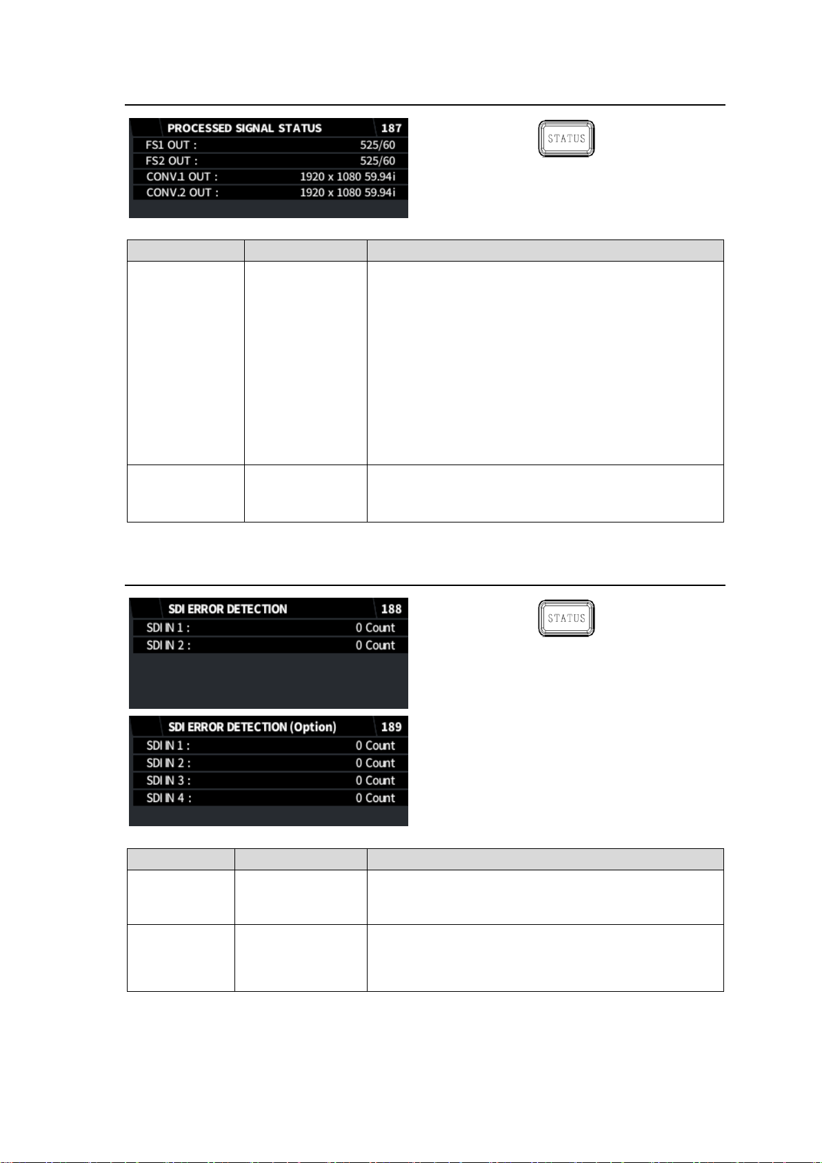
5-32. PROCESSED SIGNAL STATUS
Item
Display
Description
FS1 OUT
FS2 OUT
Loss
525/60
625/50
1080/59i
1080/50i
720/59p
720/50p
1080/23PsF
1080/24PsF
1080/59p
1080/50p
Bypass
Unknown
Displays the FS1 output signal format.
Displays the FS1 output signal format.
Loss: No input signal
Bypass: Input signal is passed through to output.
Unknown: Input signal is not supported.
CONV.1 OUT
CONV.2 OUT)
(Same as above)
Displays the CONV1 (converter) output signal format.
Displays the CONV2 (converter) output signal format.
(FA-96UDC required)
Item
Display
Description
SDI IN 1
SDI IN 2
Number of errors
Displays the input signal error (TRC and CRC) count for
SDI IN1-2.
To reset the count, press F1/F2 Unity.
SDI IN 1
SDI IN 2
SDI IN 3
SDI IN 4
Number of errors
Displays the input signal error (TRC, CRC) count for
optional SDI IN1-4. (FA-96EX3G44-R, Slot A)
To reset the count, press each Unity button.
5-33. SDI ERROR DETECTION
48
Page 49
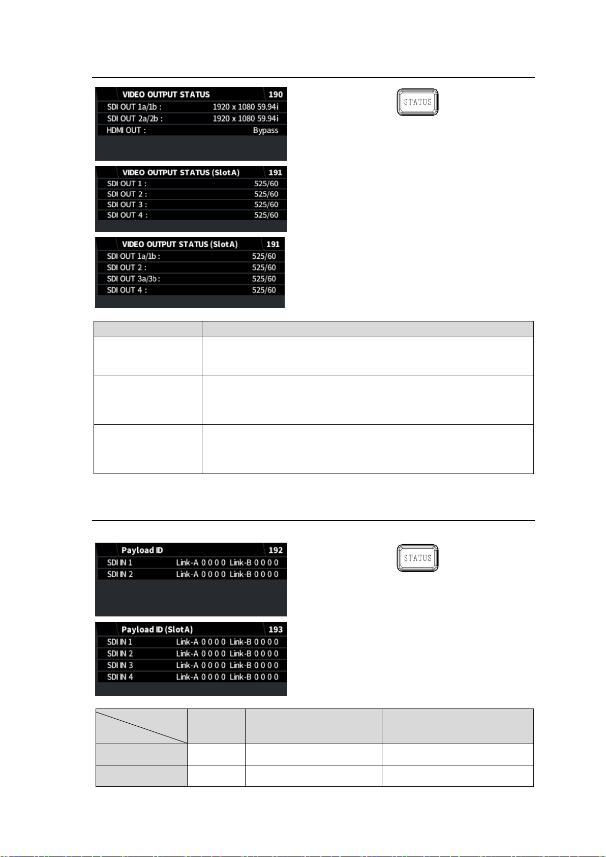
5-34. VIDEO OUTPUT STATUS
Item
Description
SDI OUT 1a/1b
SDI OUT 2a/2b
HDMI OUT
Displays each output signal format.
SDI OUT 1
SDI OUT 2
SDI OUT 3
SDI OUT 4
Displays each output signal format.
(FA-96EX3G44-R, Slot A)
SDI OUT 1a/1b
SDI OUT 2
SDI OUT 3a/3b
SDI OUT 4
Displays the output signal format.
(FA-96EX12G06, Slot A)
SDI signal
Display
SD/HD
3G Level A
3G Level B
Link A data
No display
Payload ID in Y signal
Payload ID in Link A
Link B data
No display
Payload ID in C signal
Payload ID in Link B
5-35. Payload ID (FA-96EX3G44-R)
The Payload ID (Slot A) page is displayed when FA-96EX3G44-R is installed.
49
Page 50
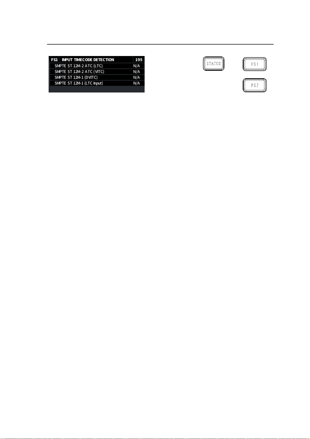
5-36. INPUT TIMECODE DETECTION
Displays the timecode detection status in the SDI input and LTC IN (FA-96DIN1-CBL).
50
Page 51
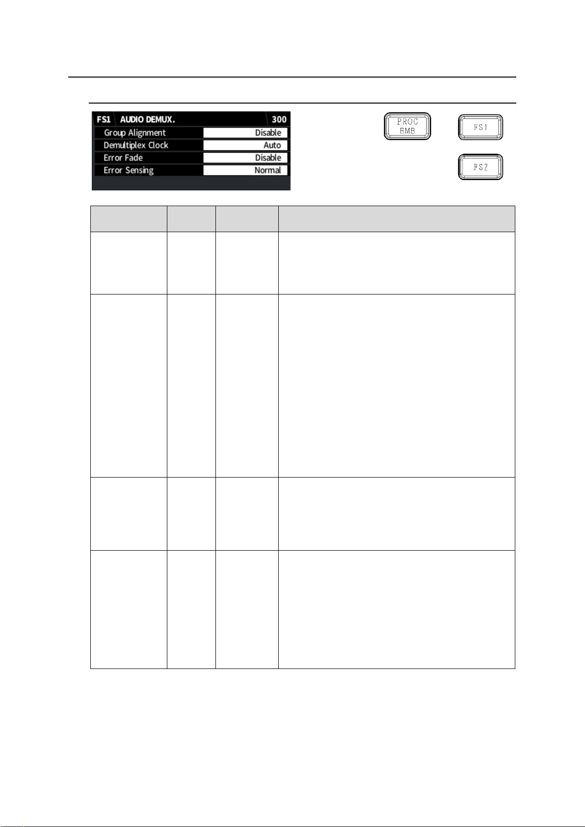
6. Audio Setting Menus
Item
Default
Setting
range
Description
Group
Alignment
Disable
Enable
Disable
Selects whether to perform auto phase adjustment
among each SDI input audio group.
Enable: Performs auto adjustment.
(*1)
Disable: Performs no auto adjustment (Normal
setting).
Demultiplex
Clock
Auto
Auto
Sync SDI
Audio Clock
Selects the audio de-embedding method for SDI
input.
Auto: Uses the audio clock phase data in the SDI
input to de-embed audio independently for each
group (Synchronous or asynchronous
de-embedding). If the audio phase data is
incorrect or de-embedded audio has noticeable
jitter, audio channels in all groups are de-embed
synchronously.
Sync SDI: Synchronously de-embeds audio
channels in all groups without using the audio
clock phase data.
Audio Clock: Uses the audio clock phase data in
the SDI input to de-embed audio independently
for each group (Synchronous or asynchronous
de-embedding).
Error Fade
Disable
Disable
Enable
Selects the way to handle output audio when an
error is detected in the input audio.
Disable: Passes through input audio without using
any effects.
Enable: Fades out and mutes audio when an input
error is detected and fades in when recovered.
Error Sensing
Normal
Disable
Normal
Sensitive
Selects the input audio error detection mode used for
Error Fade above.
Disable: Detects no errors for Error Fade. Normally
do not use.
Normal: Detects SDI signal switching, ADP (Audio
Data Packet) change and DBN (Data Block
Number) switching as Error Fade errors.
Sensitive: Adds channel status change and EDP
(Extended Data Packet) change (SD-SDI only)
to those described above as Error Fade errors.
6-1. AUDIO DEMUX
(*1)
Note that setting Enable resets all groups even when phase adjustment is performed in a
group.
51
Page 52
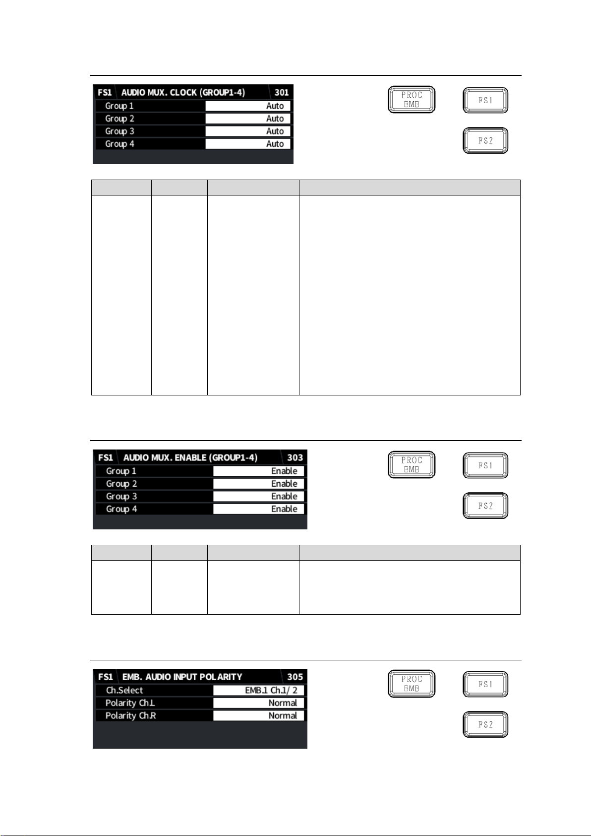
6-2. AUDIO MUX CLOCK (GROUP1-4)
Item
Default
Setting range
Description
Group 1
Group 2
Group 3
Group 4
Auto
Auto
Reference
Input Ch X/X
Input Ch X/X
Selects an audio clock for each group used for
SDI embedding.
Auto: Uses a non-PCM audio if it is included in
an audio group to be embedded. If there are
multiple non-PCM audio channels in a
group, a clock of the channel pair with the
smallest numbers is selected. Uses a clock
synced with the output video if all group
channels are PCM.
Reference: Uses a clock synced with the output
video (Synchronous output with SRC).
CH 1/2 to 15/16: Uses a selected input channel
clock. To output audio asynchronously,
select the non-PCM audio channel for use.
Reference is always applied to SD-SDI input
regardless of this setting.
Item
Default
Setting range
Description
Group 1
Group 2
Group 3
Group 4
Enable
Enable
Disable
Enables/disables SDI embedding for each audio
group.
6-3. AUDIO MUX ENABLE (GROUP1-4)
6-4. EMD. AUDIO INPUT POLARITY
52
Page 53
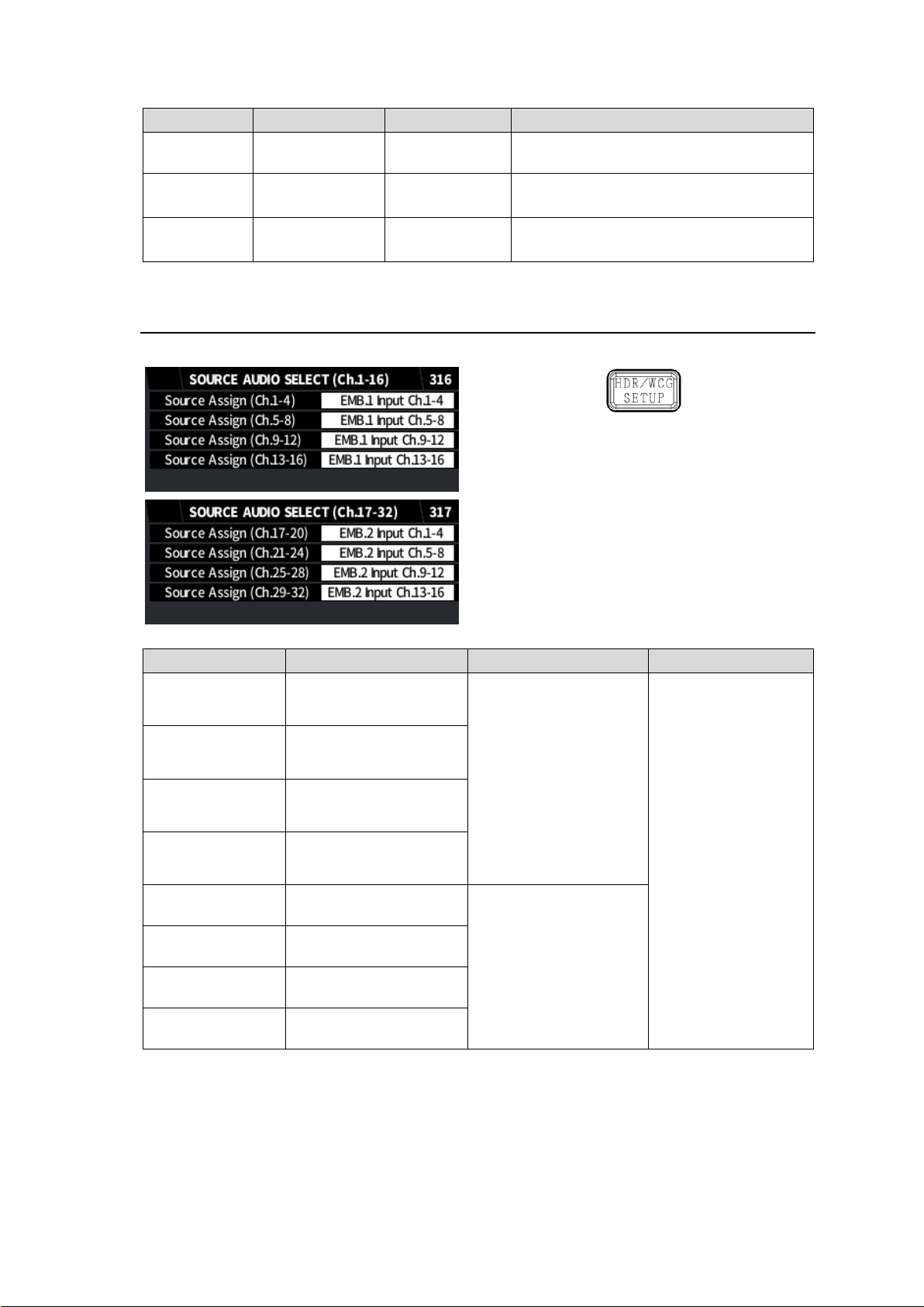
Item
Default
Setting range
Description
Ch.Select
EMB.1 Ch.1/2
Input Ch.1/2 to
Input Ch.15/16
Selects a channel pair from embedded
audio input.
Polarity Ch.L
Normal
Normal
Invert
Selects the L (odd number) channel
polarity.
Polarity Ch.R
Normal
Normal
Invert
Selects the R (even number) channel
polarity.
Item
Default
Setting range
Description
Source Assign
(Ch.1-4)
EMB.1 Input Ch.1-4
EMB1 Input Ch.1-4
EMB1 Input Ch.5-8
EMB1 Input Ch9-12
EMB1 Input Ch.13-16
EMB2 Input Ch.1-4
EMB2 Input Ch.5-8
EMB2 Input Ch.9-12
EMB2 Input Ch.13-16
AES Input Ch.1-4
AES Input Ch.5-8
AES(OP) Input Ch.1-4 *
AES(OP) Input Ch.5-8 *
Selects audio source
channels per 4
channels.
* AES (OP) Input
Ch.1-8: Requires
FA-96AES-UBL.
Source Assign
(Ch.5-8)
EMB.1 Input Ch.5-8
Source Assign
(Ch.9-12)
EMB.1 Input Ch.9-12
Source Assign
(Ch.13-16)
EMB.1 Input Ch.13-16
Source Assign
(Ch.17-20)
EMB.2 Input Ch.1-4
EMB1 Input Ch.1-4
EMB1 Input Ch.5-8
EMB1 Input Ch9-12
EMB1 Input Ch.13-16
EMB2 Input Ch.1-4
EMB2 Input Ch.5-8
EMB2 Input Ch.9-12
EMB2 Input Ch.13-16
Source Assign
(Ch.21-24)
EMB.2 Input Ch.5-8
Source Assign
(Ch.25-28)
EMB.2 Input Ch.9-12
Source Assign
(Ch.29-32)
EMB.2 Input Ch.13-16
6-5. SOURCE AUDIO SELECT
This menu allows you to select 32 audio source channels processed on the FA-9600.
53
Page 54
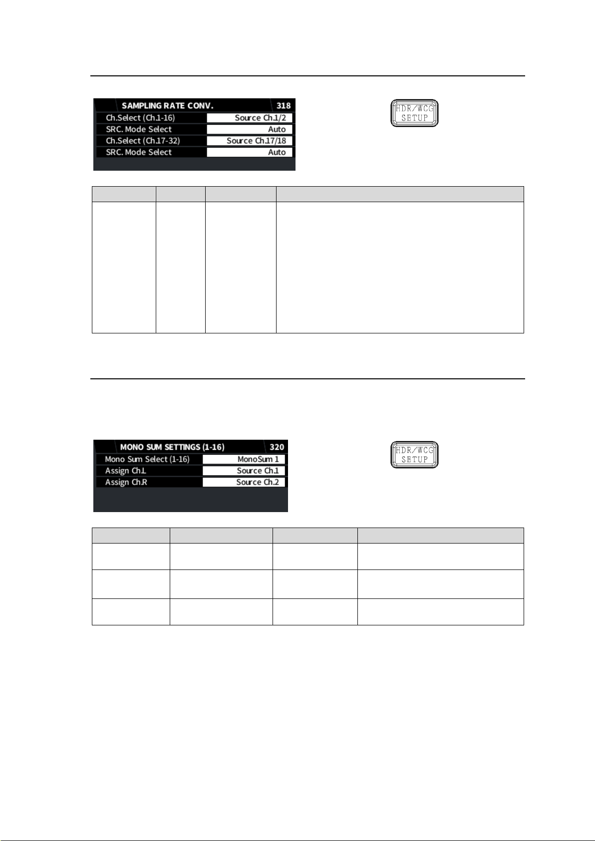
6-6. SAMPLING RATE CONVERTER (SRC)
Item
Default
Setting range
Description
SRC Mode
Select
Auto
Auto
SRC In
Bypass
Sets the SRC processing mode for each channel pair.
Auto: PCM audio is processed by the SRC. Non-PCM
audio is not processed by the SRC.
Bypass: Avoids the SRC. Use Bypass for non-PCM
audio. Note that to embed non-PCM audio to the
SDI output, audio clock should be properly
selected in the AUDIO MUX CLOCK (301) menu.
SRC In: Both PCM and non-PCM audio is processed
by SRC. Note that SRC-processed audio may not
be played properly if it is a true non-PCM audio
signal.
Item
Default
Setting range
Description
Mono Sum
Select (1-16)
MonoSum1
MonoSum1-16
Selects a MONO SUM circuit.
Assign Ch.L
Source Ch.1-31
(odd channel)
Source Ch.1-32
Selects the L-channel source.
Assign Ch.R
Source Ch.2-32
(even channel)
Source Ch.1-32
Selects the R-channel source.
Selects an audio pair under Ch. Select and the SRC processing mode under SRC Mode Select.
6-7. MONO SUM SETTINGS (1-16)
FA-9600 units are equipped with 16 MONO SUM circuits whose sources can be selected from
FA-9600 audio source channels 1-32. MONO SUM output audio can be used for SDI embedded
audio (EMB. AUDIO OUTPUT MAPPING menu, 345) and AES output audio (AES AUDIO
OUTPUT MAPPING, 347).
54
Page 55
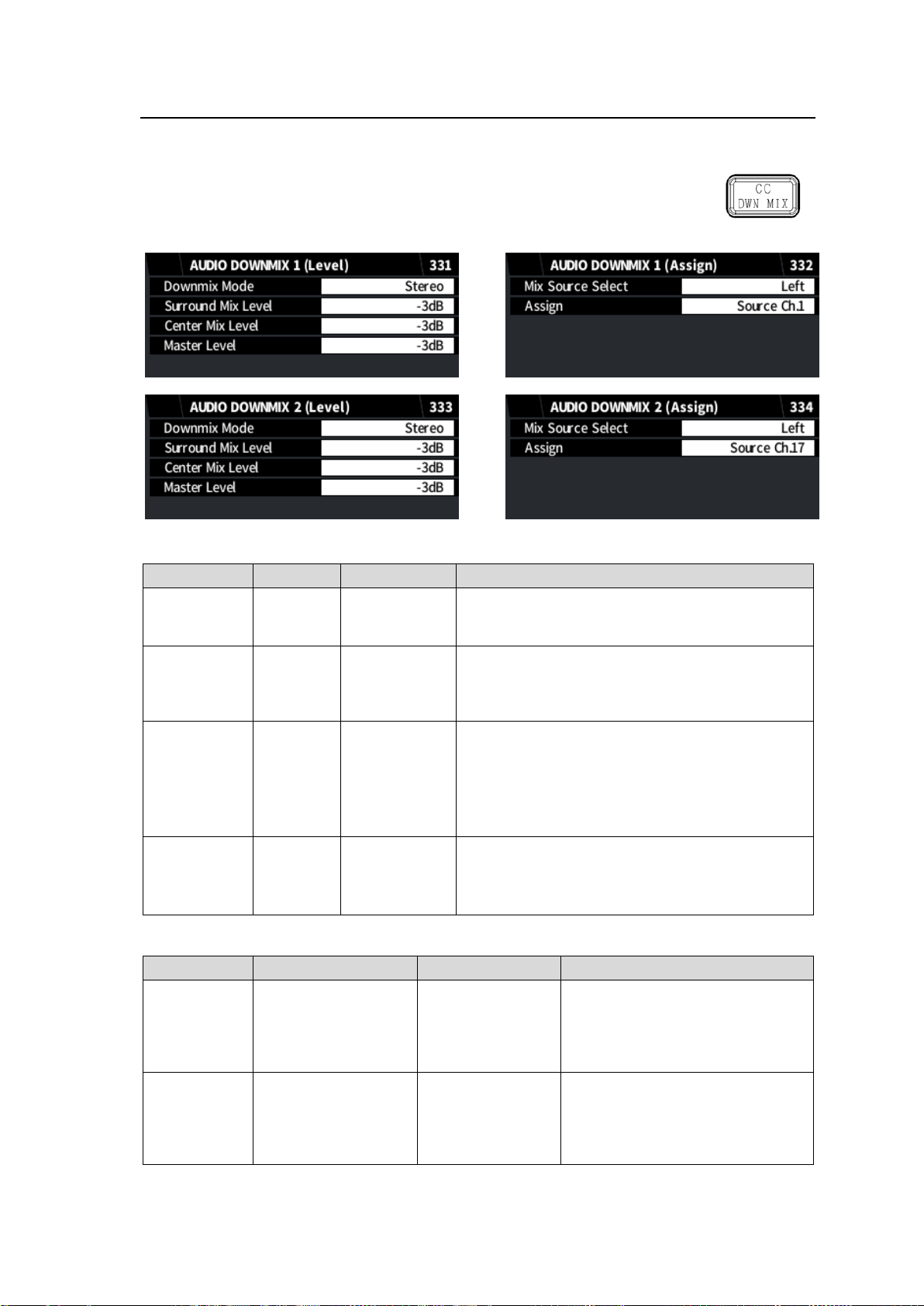
6-8. AUDIO DOWNMIX 1 and 2
Item
Default
Setting range
Description
Downmix
Mode
Stereo
Stereo
Surround
Monaural
Selects the Downmix mode.
Surround Mix
Level
-3dB
-3dB
-6dB
-9dB
Off
Sets the Ls/Rs (Surround channels) level.
Setting to Off removes the Ls/Rs channels from
mixing sources.
Center Mix
Level
-3dB
-3dB
-4.5 dB
-6dB
Sets the C (Center channel) level.
To use the same level as audio sources, set to
-3dB.
The L/R channel volume of downmixed audio may
sound too large. In such cases, decrease the
Center level to -4.5dB or -6dB.
Master Level
-3dB
-3dB
0dB
Auto
Sets the entire downmix audio level.
If set to Auto, Down MIX Master Level changes
according to Down Mix Mode and Surround Mix
Level settings.
Item
Default
Setting range
Description
Mix Source
Select
Left
Left
Right
Center
Ls
Rs
Selects a source channel for
downmixing.
Assign
Left: Source Ch.1
Right: Source Ch.2
Center: Source Ch.3
Ls: Source Ch.5
Rs: Source Ch.6
Source Ch.1-32
500Hz Tone
1kHz Tone
Silence
Selects an audio source for the
selected channel.
FA-9600 units are equipped with 2 Audio Downmix modules, which can accept FA-9600 audio
source channels 1-32, 1 kHz and 500 Hz test signals and Silence as Downmix sources.
Downmix output audio can be used for SDI embedded audio (EMB. AUDIO
OUTPUT MAPPING menu, 345) and AES output audio (AES AUDIO OUTPUT
MAPPING, 347).
Downmix 1/2(Level)
Downmix 1/2(Assign)
55
Page 56
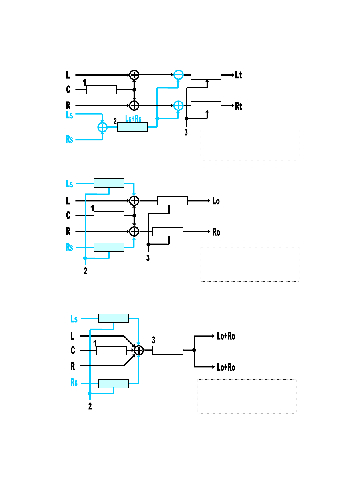
Down Mix Block Diagram
1: CENTER MIX level setting
2: SURROUND MIX level setting
3: MASTER LVL setting
* LFE channel is not subjected to the mix.
Gain Adjust
Gain Adjust
Gain Adjust
Gain Adjust
Gain Adjust
Gain Adjust
Gain Adjust
Gain Adjust
Gain Adjust
1: CENTER MIX level setting
2: SURROUND MIX level setting
3: MASTER LVL setting
* LFE channel is not subjected to the mix.
Gain Adjust
Gain Adjust
Gain Adjust
Gain Adjust
1: CENTER MIX level setting
2: SURROUND MIX level setting
3: MASTER LVL setting
* LFE channel is not subjected to the mix.
<Surround Mix (Lt/Rt)>
Ls/Rs surround channels are summed to produce a mono surround channel and mixed to right and
left channels by the 180 degree phase difference. (LFE channel is discarded.)
<Stereo Mix (Lo/Ro)>
For Stereo Monitors
<Monaural Mix (Lo+Ro/Lo+Ro)>
For Monaural Monitors
56
Page 57
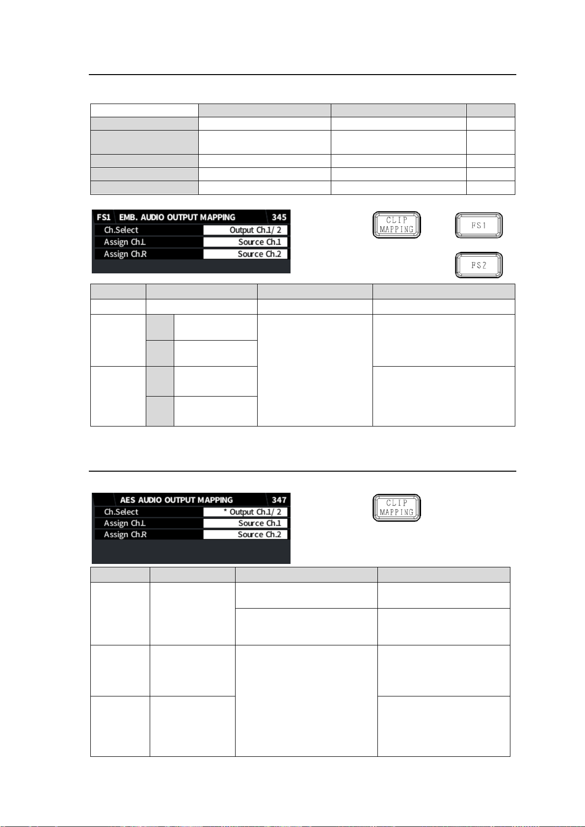
6-9. EMB. AUDIO OUTPUT MAPPING
Audio source signal
Description
Reference menu
Menu no.
Output Source Ch.1-32
Audio source channels 1-32
SOURCE AUDIO SELECT
316-317
Downmix 1L/1R
Downmix 2L/2R
Downmix 1 output
Downmix 2 output
AUDIO DOWN MIX1
AUDIO DOWN MIX2
331-332
333-334
Mono Sum Ch1-16
16 Mono Sum output
MONO SUM SETTINGS (1-16)
320
1kHz Tone, 500Hz Tone
Test signals
Silence
Silence signal
Item
Default
Setting range
Description
Ch.Select
Output Ch.1/2
Output Ch.1/2-15/16
Selects an output channel pair.
Assign
Ch.L
FS1
Source Ch.1-15
(Odd channel)
Source Ch.1-32
500Hz Tone
1kHz Tone
Silence
Downmix 1_L
Downmix 1_R
Downmix 2_L
Downmix 2_R
Mono Sum 1-16
Selects the L channel source.
FS2
Source Ch.17-31
(Odd channel)
Assign
Ch.R
FS1
Source Ch.2-16
(Even channel)
Selects the R channel source.
FS2
Source Ch.18-32
(Even channel)
Item
Default
Setting range
Description
Ch.Select
Output Ch.1/2
Output Ch.1/2-7/8
Selects an output channel
pair.
(OP) Output Ch.1/ 2-7/8
Selects an output channel
pair. (FA-96AES-UBL
required)
Assign
Ch.L
Source Ch.1-7
(Odd channels)
Source Ch.1-32
500Hz Tone
1kHz Tone
Silence
Downmix 1_L
Downmix 1_R
Downmix 2_L
Downmix 2_R
Mono Sum 1-16
Selects the L channel
source.
Assign
Ch.R
Source Ch.2-8
(Even channels)
Selects the R channel
source.
Allows you to assign the following audio signals to SDI output and AES output audio channels.
6-10. AES AUDIO OUTPUT MAPPING
Allows you to select AES output audio from the same audio sources as those for SDI output.
57
Page 58
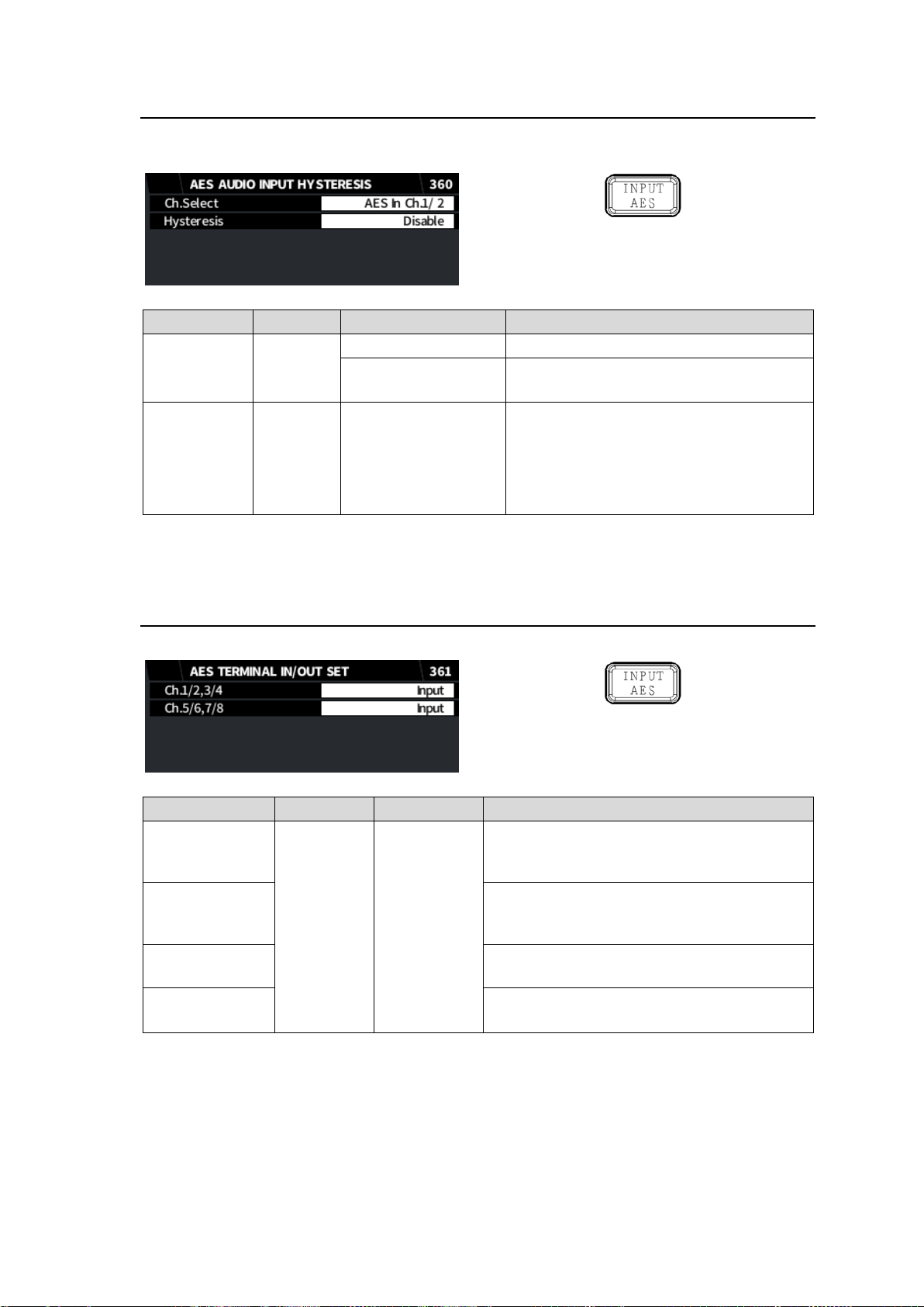
6-11. AES INPUT HYSTERESIS
Item
Default
Setting range
Description
Ch. Select
AES In
Ch. 1/2
AES In Ch. 1/2-7/8
Selects an AES input channel pair.
AES(OP) In
Ch.1/ 2-7/8
Selects an AES input channel pair.
(FA-96AES-UBL required)
Hysteresis
Disable
Disable
Group A
Group B
Disable: Disables channel alignment.
Group A/B: Adds the channel pair to a
group (A or B) and aligns audio word
timing within the channel group by
referring to the smallest channel pair.
(*1)
Item
Default
Setting range
Description
Ch.1/2,3/4
Input
Input
Output
Selects Input or Output for DIGITAL AUDIO
IN/OUT1/2 and 3/4.
* Fixed to Input if FA-96AES-UBLC installed.
Ch.5/6,7/8
Selects Input or Output for DIGITAL AUDIO
IN/OUT5/6 and 7/8.
* Fixed to Input if FA-96AES-UBLC installed.
Ch.1/2,3/4(OP)
Selects Input or Output for 1/2 and 3/4 on
FA-96AES-UBL.
Ch.5/6,7/8(OP)
Selects Input or Output for 5/6 and 7/8 on
FA-96AES-UBL.
Allows you to align timing of AES input channels by grouping them.
This function is useful for multi-channel audio input such as surround sound.
(*1)
If the reference audio is lost, the next smallest channel pair is used. Timing adjustment ranges
within ±0.25 samples.
6-12. AES TERMINAL IN/OUT SET
Allows you to select Input or Output for AES terminals.
58
Page 59
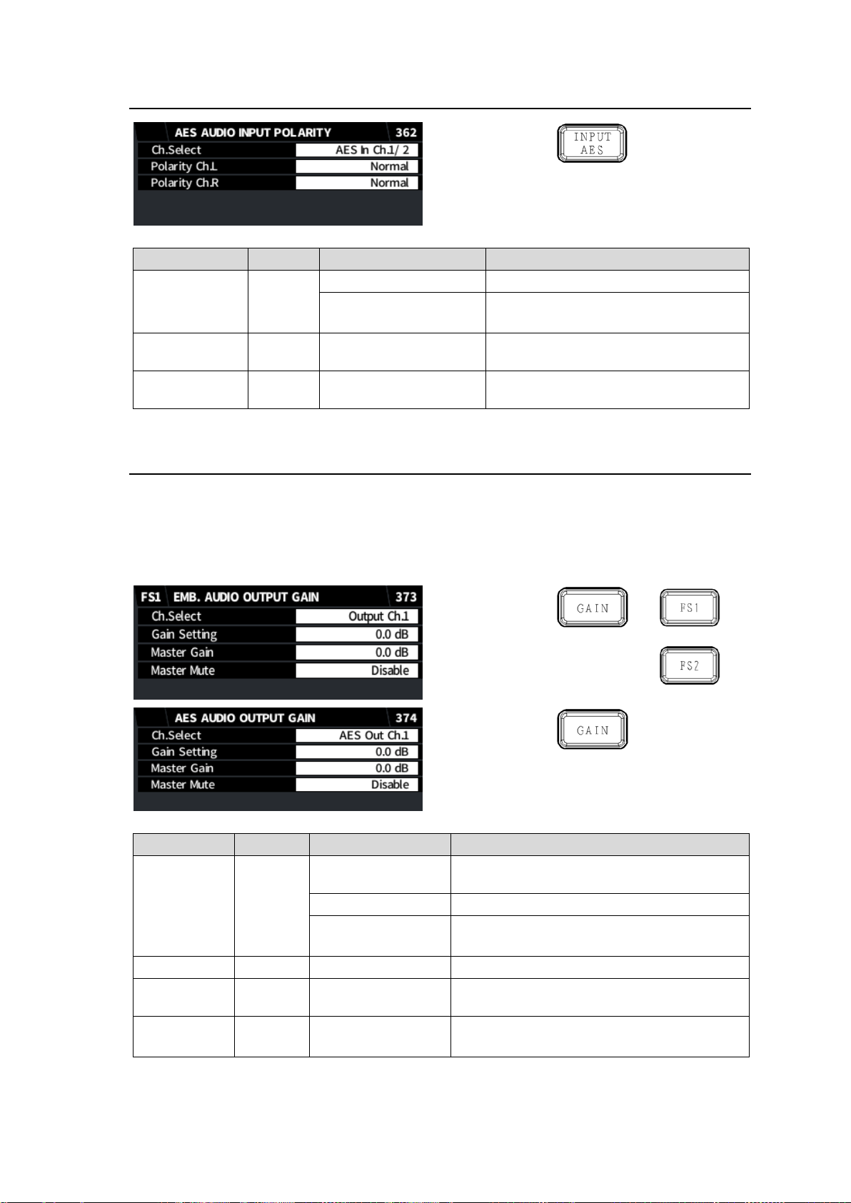
6-13. AES AUDIO INPUT POLARITY
Item
Default
Setting range
Description
Ch.Select
AES In
Ch.1/2
AES In Ch.1/2-7/8
Selects an AES input channel pair.
AES(OP) In Ch.
1/ 2-7/8
Selects an AES input channel pair.
(FA-96AES-UBL required)
Polarity Ch.L
Normal
Normal
Invert
Selects the polarity for the L (odd)
channel.
Polarity Ch.R
Normal
Normal
Invert
Selects the polarity for the R (even)
channel.
Item
Default
Setting range
Description
Ch. Select
Output
Ch.1
Output Ch.1 to 16
Selects a channel from audio to be
embedded into SDI output.
AES Out Ch1 to 8.
Selects an audio channel from AES output.
AES(OP) Out
Ch.1-8
Selects an audio channel from AES output.
(FA-96AES-UBL required)
Gain Setting
0.0dB
-20.0dB to +20.0dB
Sets the gain for the audio channel.
Master Gain
0.0dB
-20.0dB to +20.0dB
Sets the gain offset for all (embedded or
AES) channels.
Master Mute
Disable
Disable
Enable
Enable: Mutes all (embedded or AES) audio
channels.
6-14. AUDIO OUTPUT GAIN
Allows you to adjust output audio gain for the following channels:
SDI output audio (EMB. AUDIO OUTPUT MAPPING menu, 345)
AES output audio (AES AUDIO OUTPUT MAPPING menu, 347)
Allowable gain adjustment ranges from -20 dB to 20 dB with Master Gain and individual channel
Gain. Gain values exceeding these limits are clipped and set to the respective limit value.
59
Page 60
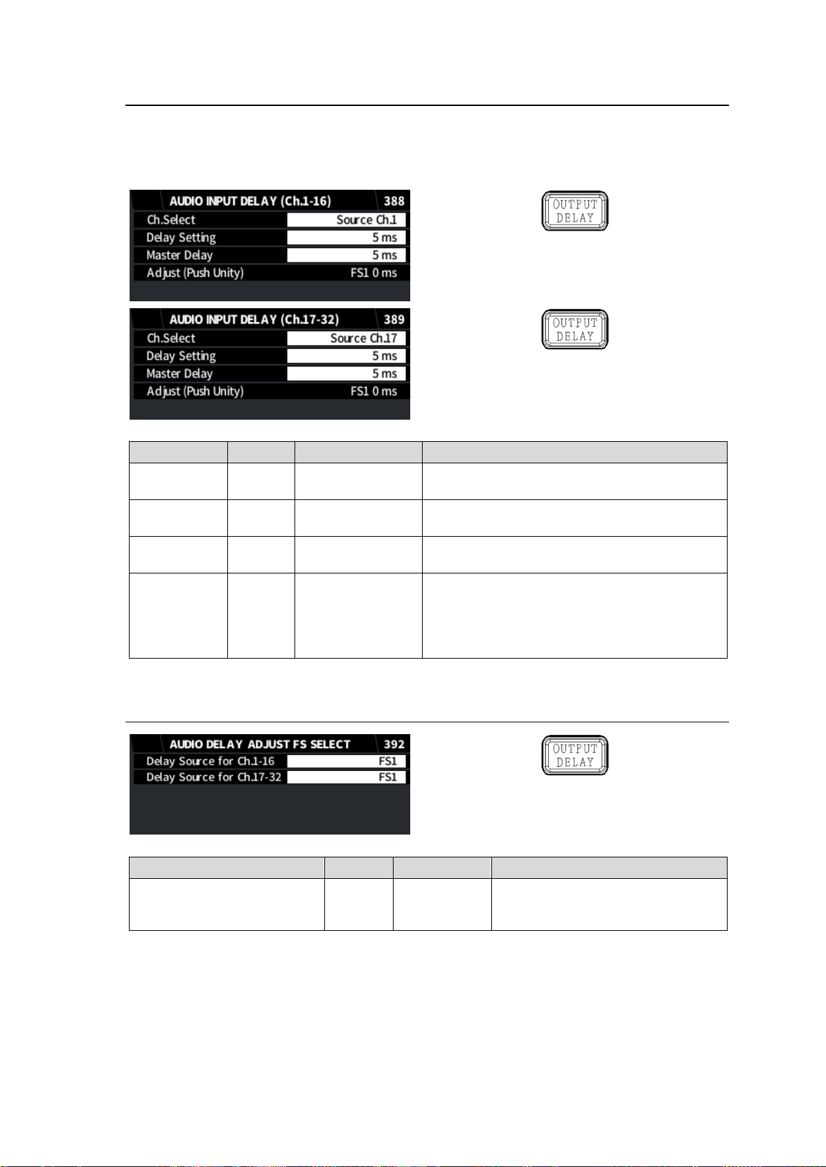
6-15. AUDIO INPUT DELAY
Item
Default
Setting range
Description
Ch.Select
Source
Ch.1
Source Ch.1-32
Selects an audio channel.
Delay Setting
5 ms
5 ms to 1,000 ms
Sets the delay added to the channel. Master
Delay is already added to the displayed value.
Master Delay
5 ms
5 ms to 1,000 ms
Sets the delay offset for all 16 channels in each
page.
Adjust
(Push Unity)
-
-
Displays video delay for FS1 or FS2 (selected in
AUDIO DELAY AJUST FS SELECT menu)
video delay.
Pressing F4-UNITY sets Master Delay to the
displayed FS video delay.
Item
Default
Setting range
Description
Delay Source for Ch.1-16
Delay Source for Ch.17-32
FS1
FS1
FS2
Selects an FS to be displayed under
Adjust in the AUDIO INPUT DELAY
menu.
Allows you to add delay to 32 audio sources on the FA-9600. (See SOURCE AUDIO SELECT
menu, 316-317). Allowable delay amount ranges from 5 msec to 1000 msec with Master Delay and
individual channel Delay. Delay values exceeding these limits are clipped and set to the respective
limit value.
6-16. AUDIO DELAY ADJUST FS SELECT
60
Page 61
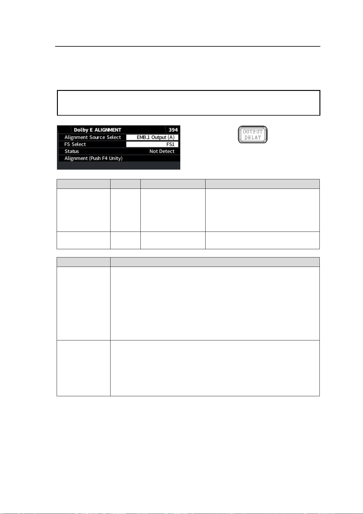
6-17. DOLBY E ALIGNMENT
Notes on Dolby Alignment function
Dolby Alignment function requires one frame delay (max).
To make the function effective, Dolby E and output video signals should be synchronized
and have the same frame rate.
Item
Default
Setting range
Description
Alignment
Source Select
EMB.1
Output
(A)
EMB.1 Output (A)
EMB.1 Output (B)
EMB.2 Output (A)
EMB.2 Output (B)
AES Output (A)
AES Output (B)
Selects an audio output.
FS Select
(AES output only)
FS1
FS1
FS2
If the selected audio is AES, select an
FS (SDI) for the timing reference.
Item
Description
Status
Displays the output channel number and the timing reference line in the SDI
signal.
If signals are unavailable, “Error” is displayed. If no Dolby E signals are
detected, “Not detected” is displayed.
[NOTE] If multiple Dolby E channels are detected, the Dolby E alignment
source is set to the smallest number of channel. If two or more Dolby E
channels are detected in EMB1, EMB2, AES Output respectively, the
smallest number of channel is assigned to Source (A) and next smaller
channel is assigned to Source (B).
Alignment (Push
Unity)
Press F4 Unity to execute the audio source (output) alignment.
Audio alignment settings are disabled and reset under the following
conditions
- When the Dolby E is changed to another audio.
- When an event is loaded
- When the FA-9600 is reset to default
- When the FA-9600 is powered off.
The Dolby E Alignment function allows you to adjust the Dolby E input timing to an SDI output by
aligning the Dolby E burst start point to the appropriate SDI line. Two aligners (A and B) are
available on EMB1, EMB2 and AES outputs respectively.
61
Page 62
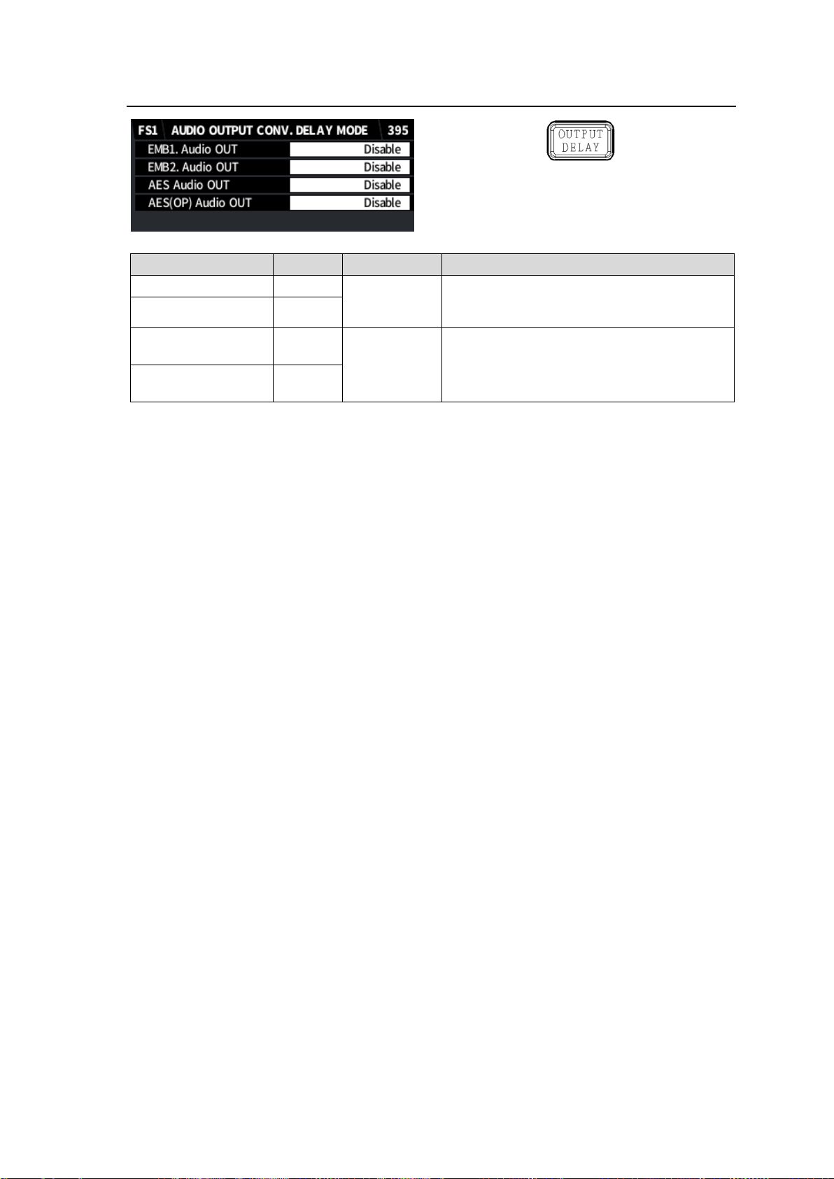
6-18. AUDIO OUTPUT CONV. DELAY MODE
Item
Default
Setting range
Description
EMB1. Audio OUT
Disable
Disable
Enable
Enables/disables converter additional delay
adjustment for audio to be embedded on the
SDI output.
EMB2. Audio OUT
Disable
AES Audio OUT
Disable
Disable
Enable(FS1)
Enable(FS2)
Enables/disables converter additional delay
adjustment for AES audio output from FS1 or
FS2.
AES(OP) Audio
OUT
Disable
62
Page 63
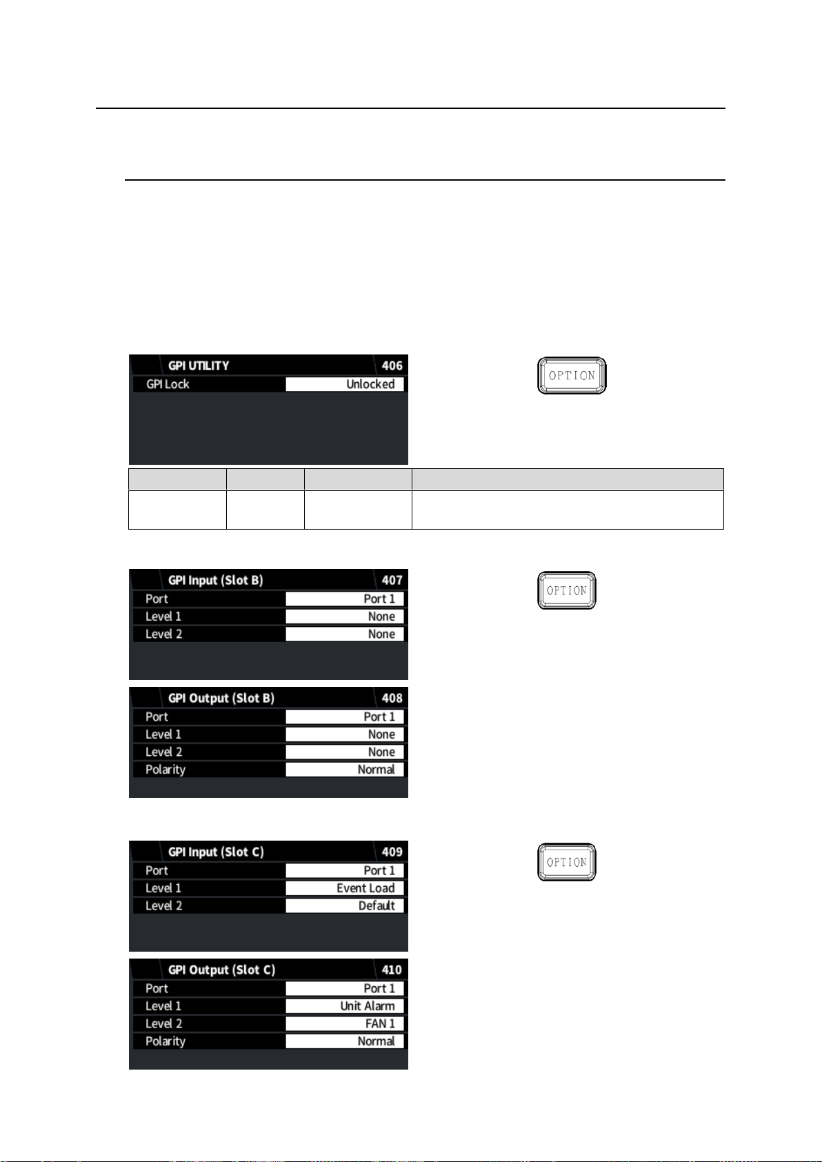
7. System Setting Menus
Item
Default
Setting range
Description
GPI Lock
Unlocked
Unlocked
Locked
Unlocked: Enables GPI inputs.
Locked: Disables GPI inputs.
The following menu allows you to overall FA-9600 settings and applied to both FS1 and FS2.
7-1. GPI UTILITY / INPUT / OUTPUT
FA-96GPI or FA-96DB9-CBL option is required for GPI input / output functions.
The FA-96GPI option card provides GPI 10 inputs and 10 outputs and should be installed into Slot
B or C. Refer to Sec. 3-5. “FA-96GPI (10 Inputs and 10 Outputs)” for details on the connector pin
assignments. Use the following menus to assign functions to input and output ports.
The FA-96DB9-CBL option cable provides 7 GPI input/output ports and should be installed into
Slot E. Refer to Sec. 3-4. “FA-96DB9-CBL (7 GPI Input/Output)” for details on the connector pin
assignments. Use the following menus to select input or output and assign functions to ports.
Enabling/disabling GPI inputs
GPI SETTINGS (If the FA-96GPI card installed on Slot B)
GPI SETTINGS (if the FA-96GPI card installed on Slot C)
63
Page 64
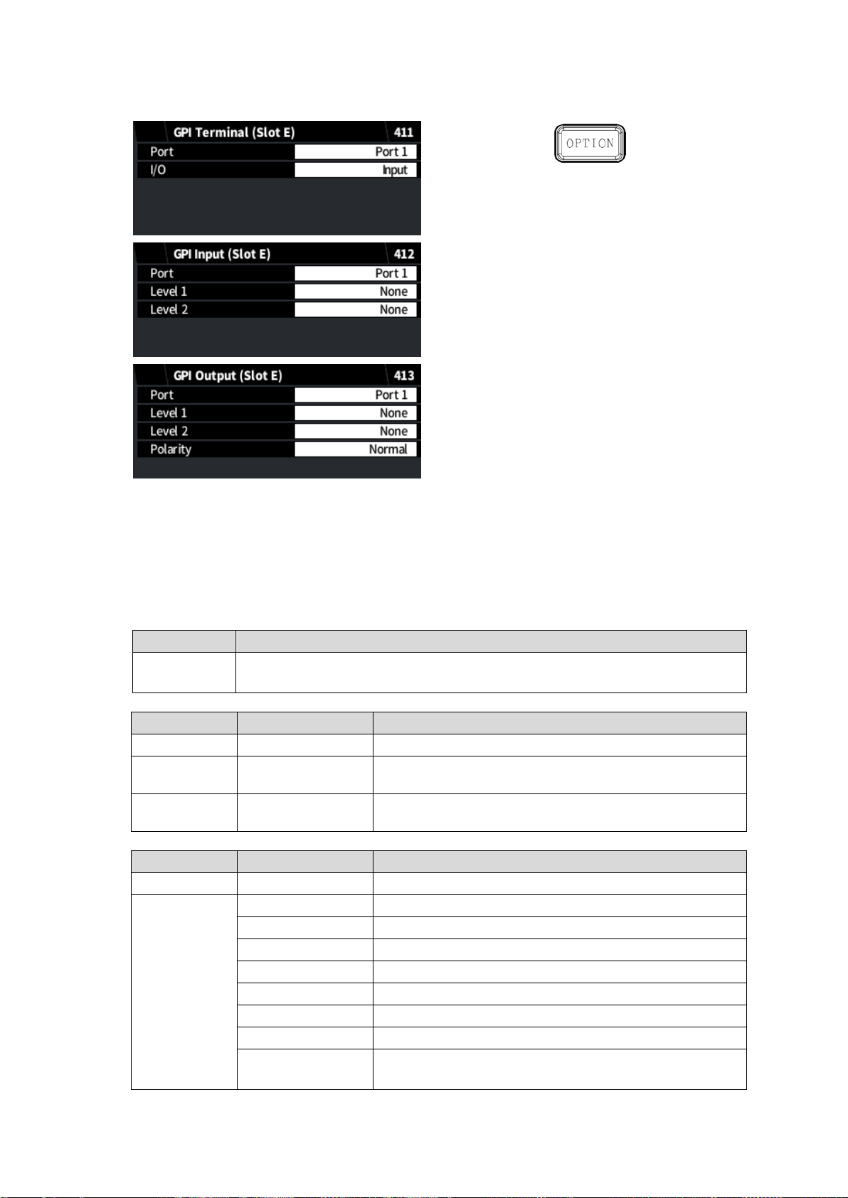
Item
Setting
I/O
Input: Sets the terminal to GPI input.
Output: Sets the terminal to GPI output.
Level 1 setting
Level 2 setting
Description
None
None
No function
Event Save
Event1 - 100
Saves settings to event by selecting an event number
under Level 2.
Event Load
Default
Event1 - 100
Loads settings from event by selecting an event number
under Level 2.
Level 1 setting
Level 2 setting
Description
None
None
No function
Unit Alarm
FAN1/2/3
Outputs an alarm when FAN 1, 2 or 3 fails.
FAN1
Outputs an alarm when FAN 1 fails.
FAN2
Outputs an alarm when FAN 2 fails.
FAN3
Outputs an alarm when FAN 3 fails.
DC Power 1/2
(*1)
Outputs an alarm when DC 1 or 2 has an error.
DC Power 1
(*1)
Outputs an alarm when DC 1 has an error.
DC Power 2
(*1)
Outputs an alarm when DC 2 has an error.
Any
Outputs an alarm when any of above occurs.
(Same as FAN1/2/3 if FA-96PS uninstalled)
GPI SETTINGS (if the FA-96DE9-CBL installed on Slot E)
GPI Settings
Select input or output. (FA-96DB9-CBL, Slot E only)
Select a port under Port and function under Level 1 and Level 2. Available Level 2 settings
will change according to Level 1 selection. Assign input functions in the GPI Input menu and
output functions in the GPI Output menu.
<GPI Terminal> (Slot E only)
<GPI Input>
<GPI Output>
(*1)
FA-96PS required
64
Page 65
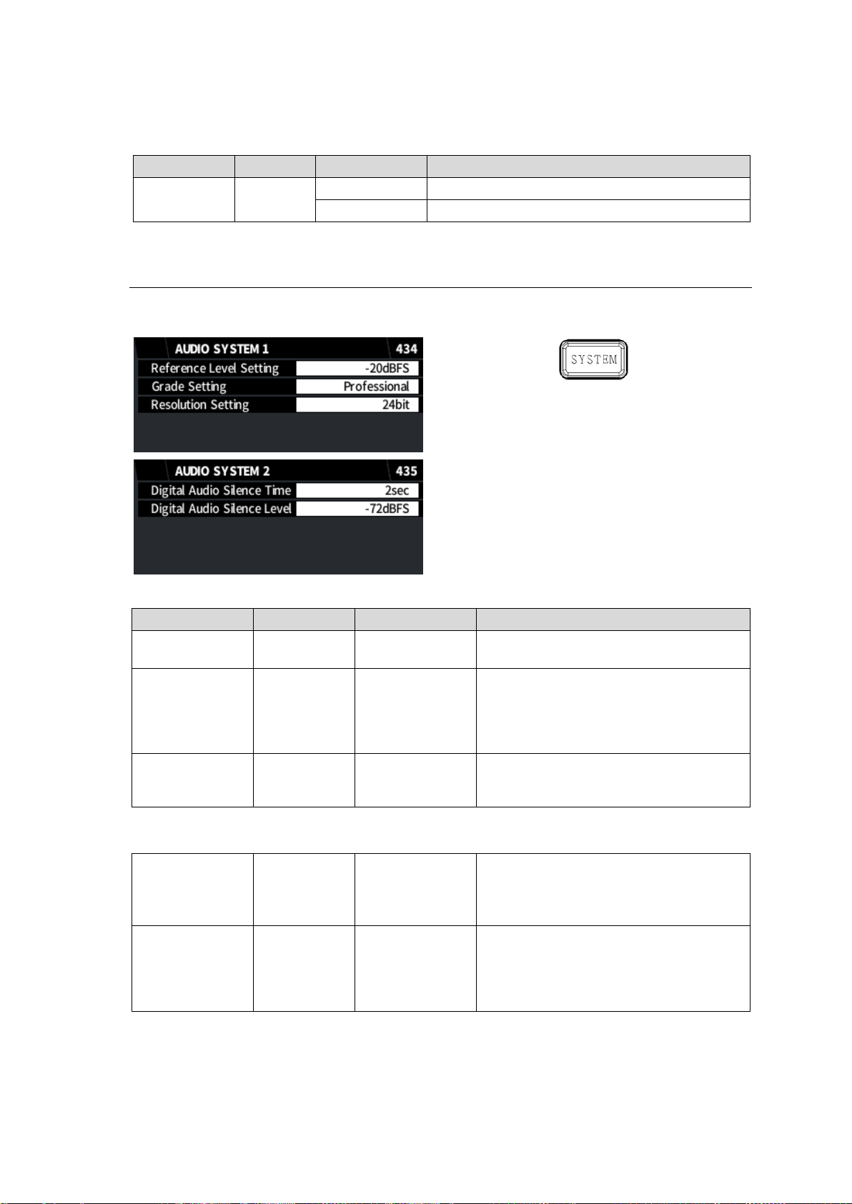
Item
Default
Setting range
Description
Polarity
Normal
Normal
Active low type
Invert
Active high type
Item
Default
Setting range
Description
Reference Level
-20 dBFS
-18 dBFS
-20 dBFS
Selects the reference level for digital
audio signals.
Grade
Professional
Professional
Consumer
Selects an audio application for AES
output.
Professional: Optimized for professional
use.
Consumer: Optimized for consumer use.
Resolution
24 bit
16 bit
20 bit
24 bit
Selects an audio word length for AES
outputs.
Digital Audio
Silence Time
2 sec
1 – 10 sec
Sets the duration to determine digital
audio signals are silent.
Digital audio signals are judged as silent
after the silent state lasts the set duration.
Digital Audio
Silence Level
-72 dBFS
-72 dBFS
-66 dBFS
-60 dBFS
-54 dBFS
-48 dBFS
Sets the audio level to determine the SDI
embedded audio and AES input signals
are silent.
Select the alarm signal polarity if Unit Alarm is selected under Level 1 according to the onnection
device polarity.
7-2. AUDIO SYSTEM 1, 2
AUDIO SYSTEM 1 settings are applied to all embedded and AES audio channels both in FS 1 and
FS 2.
AUDIO SYSTEM 1
AUDIO SYSTEM 2
65
Page 66
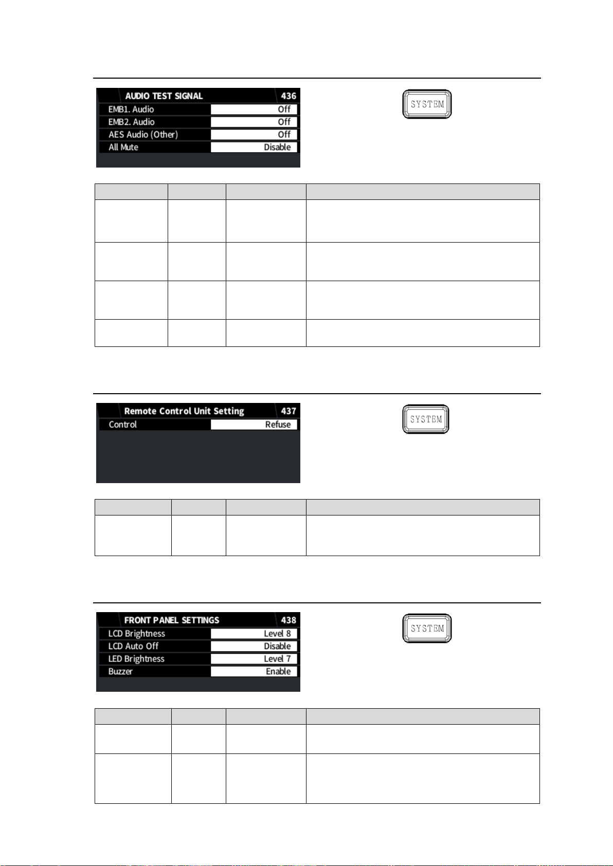
7-3. AUDIO TEST SIGNAL
Item
Default
Setting range
Description
EMB1.Audio
Off
Off
500Hz Tone
1kHz Tone
Allows you to assign an audio test signal to the
embedded audio on the FS1 SDI output.
EMB2.Audio
Off
Off
500Hz Tone
1kHz Tone
Allows you to assign an audio test signal to the
embedded audio on the FS2 SDI output.
AES.Audio
(Other)
Off
Off
500Hz Tone
1kHz Tone
Allows you to assign an audio test signal to all
AES output.
All Mute
Disable
Disable
Enable
Allows you to mute all output audio.
Item
Default
Setting range
Description
Control
Refuse
Refuse
Accept
Refuse: Accepts no remote control unit’
commands.
Accept: Accepts remote control unit’ commands.
Item
Default
Setting range
Description
LCD
Brightness
Level 8
Level 1- 15
Adjusts the LCD panel display brightness.
Level 1(dark), 15 (bright)
LCD Auto Off
Disable
Disable
5min
10min
30 min
Sets the LCD screen saver duration.
Setting to Disable disables the screen saving
feature.
7-4. Remote Control Unit Setting
7-5. FRONT PANEL SETTINGS
66
Page 67
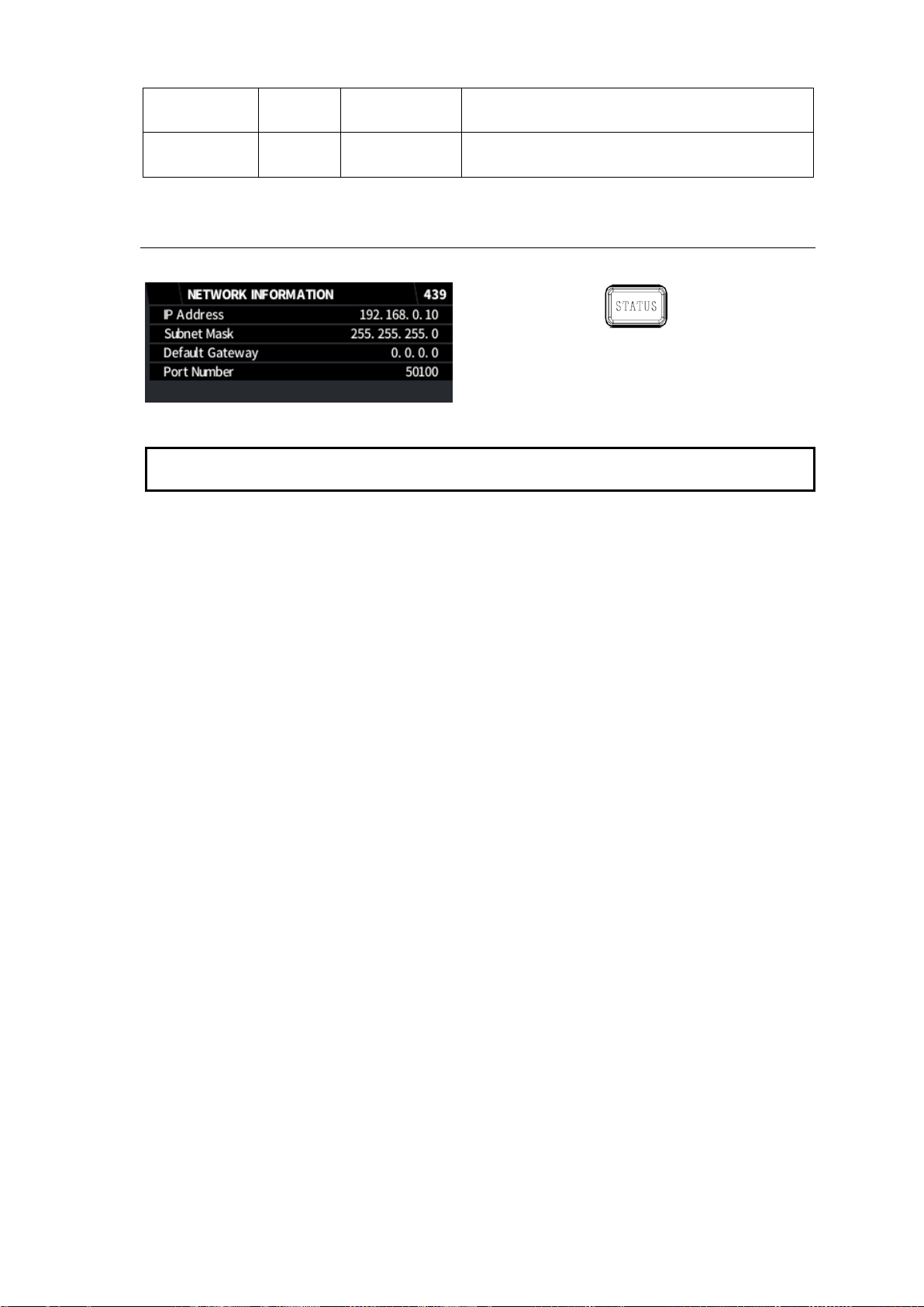
LED
Brightness
Level 7
Level 1- 15
Adjusts the brightness of button LEDs.
Level 1(dark), 15 (bright)
Buzzer
Enable
Enable
Disable
Turns the buzzer on/off.
IMPORTANT
The FA-9600 network settings cannot be changed on the front panel. Change settings in the
Windows GUI or Web GUI menu screen.
7-6. NETWORK INFORMATION
The following menu displays the FA-9600 network settings.
67
Page 68

7-7. EMB. AUDIO INPUT STATUS
Item
Display
Description
Ch.1/2
Ch.3/4
Ch.5/6
Ch.7/8
Ch.9/10
Ch.11/12
Ch.13/14
Ch.15/16
Loss
PCM
PCM (Async)
Silence
Silence (Async)
Dolby E
Dolby E (Async)
Non-PCM
Non-PCM (Async)
Blank
Displays each embedded audio
channel status of the FS1 or FS2 SDI
input.
Item
Display
Description
Ch.1/2
Ch.3/4
Ch.5/6
Ch.7/8
Loss
PCM (32kHz)
PCM (44.1kHz)
PCM (48kHz)
Silence (32kHz)
Silence (44.1kHz)
Silence (48kHz)
Dolby E
Non-PCM
Output Settings
Displays each channel status of AES audio
inputs.
Output Settings is displayed if AES ports
are set to output.
7-8. AES AUDIO INPUT STATUS
* If FA-96AES-UBL installed:
68
Page 69
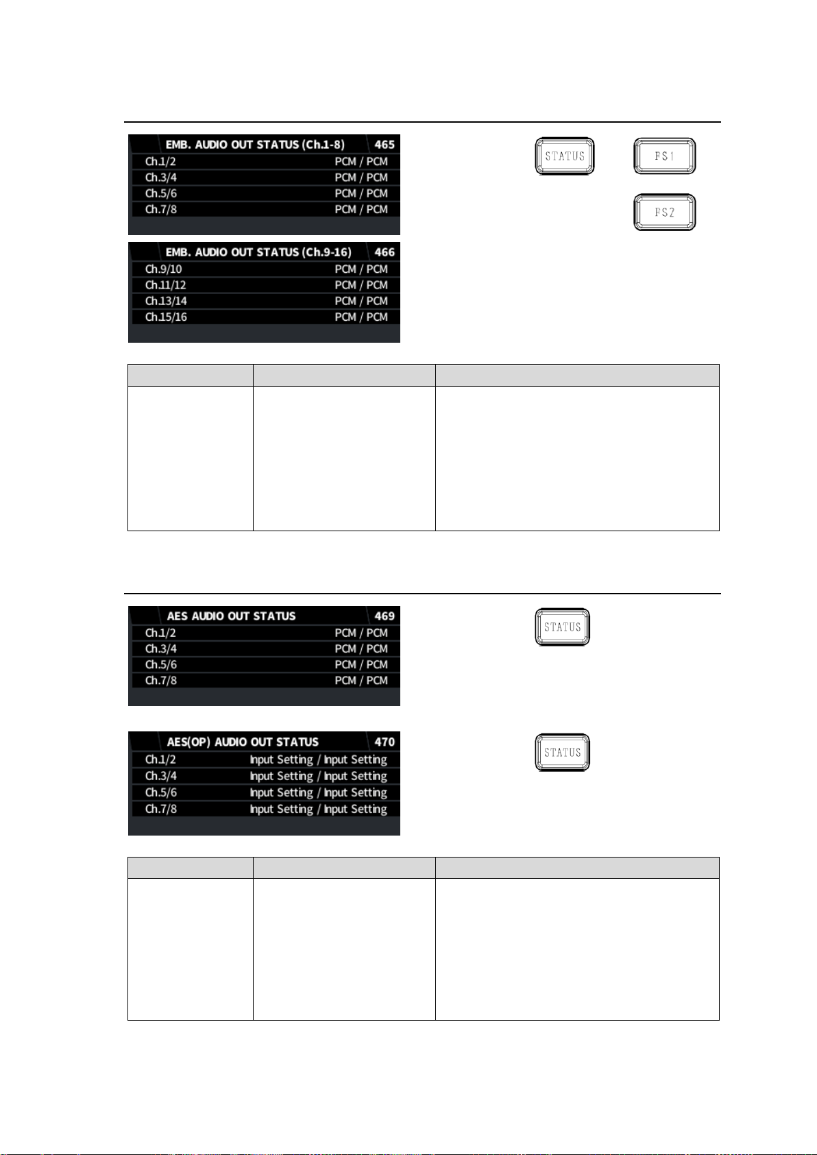
Item
Display
Description
Ch.1/2
Ch.3/4
Ch.5/6
Ch.7/8
Ch.9/10
Ch.11/12
Ch.13/14
Ch.15/16
PCM
PCM (Async)
Mute
Mute (Async)
Dolby E
Dolby E (Async)
Non-PCM
Non-PCM (Async)
Blank
Displays each embedded audio channel
status of the FS1 or FS2 SDI output.
Item
Display
Description
Ch.1/2
Ch.3/4
Ch.5/6
Ch.7/8
PCM
PCM (Async)
Mute
Mute (Async)
Dolby E
Dolby E (Async)
Non-PCM
Non-PCM (Async)
Input Setting
Displays each channel status of AES
outputs.
Input Settings is displayed if AES ports are
set to input.
7-9. EMB. AUDIO OUT STATUS
7-10. AES AUDIO OUT STATUS
If FA-96AES-UBL installed:
69
Page 70
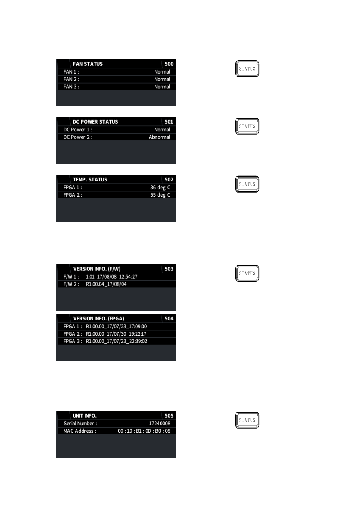
7-11. FAN / DC POWER / TEMP. STATUS
The following menu displays the FAN 1 to 3 states.
The following menu displays the Power 1 and 2 (FA-96PS) states.
The following menu displays the FPGA1 and 2 temperatures.
7-12. VERSION INFO.
The following menu displays the firmware and FPGA versions.
7-13. UNIT INFO.
The following menu displays the FA-9600 serial product number and MAC address of the network
port.
70
Page 71
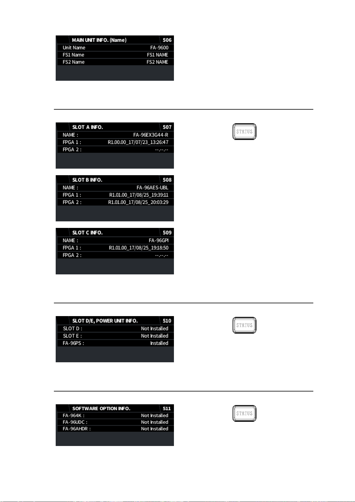
7-14. SLOT INFO.
The following menu displays the option slot status.
7-15. SLOT D/E, POWER UNIT INFO.
The following menu displays the installation status for Slot D, Slot E and FA-96PS.
7-16. SOFTWARE OPTION INFO.
The following menu displays the optional software installation status.
71
Page 72
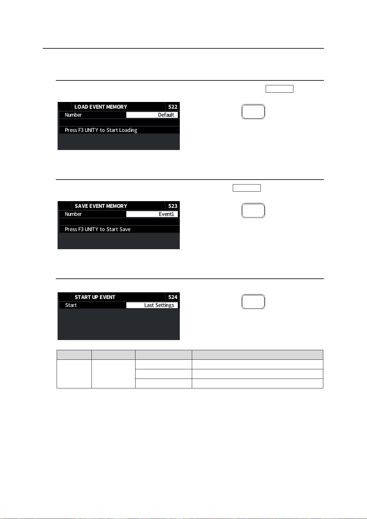
8. Event Memory
EVENT
EVENT
EVENT
Item
Default
Setting range
Description
Start
Last Settings
Last Settings
Loads the settings last used.
Default
Resets all settings to default at startup.
Event 1-100
Loads the selected event memory at startup.
Each FA-9600 unit can save and load 10 sets of event memory data.
8-1. LOAD EVENT MEMORY
Selects an event number for loading from Event1-100 and Default and press F3 UNITY to load the
event.
8-2. SAVE EVENT MEMORY
Selects an event number for saving from Event1-100 and press F3 UNITY to save settings to the
event number.
8-3. START UP EVENT
Selects an event number to be loaded when the unit power turns on.
72
Page 73
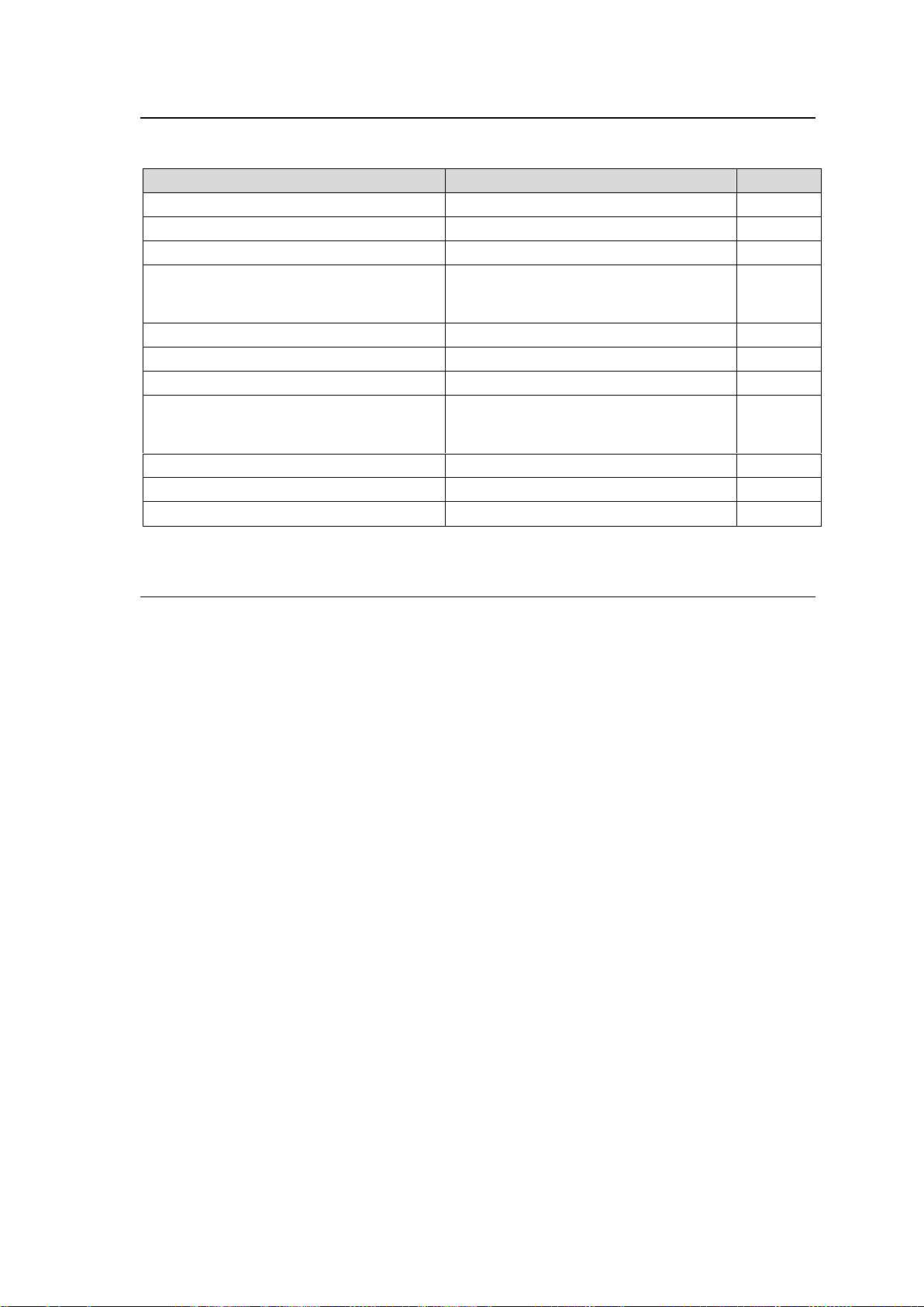
8-4. Items Not Stored in Event Memory
Menu
Items not stored
Sec.
SPLIT MODE SELECT
Mode setting
5-2
AREA MAKER
Marker
5-3
VIDEO FREEZE
Freeze
5-28
VIDEO INPUT STATUS
|
INPUT TIMECODE DETECTION
All information and status
5-31
|
5-36
AUDIO OUTPUT GAIN
Master Mute setting
6-14
GPI UTILITY / INPUT / OUTPUT
All menu settings
7-1
FRONT PANEL SETTINGS
All menu settings
7-5
NETWORK INFORMATION
|
SOFTWARE OPTION INFO.
All information and status
7-6
|
7-16
START UP EVENT
All menu settings
8-3
Main Unit tab
Unit / FS Name settings
10-1
Network tab
All menu settings
10-6
The following menu items are not stored in event memory.
8-5. Notes on Event Memory
Do not power off the FA-9600 unit while saving data to event memory. Otherwise, event data is
not stored correctly.
Wait at least 5 seconds and power off the FA-9600 unit before changing settings, since the unit
regularly auto-saves setting data. (See Sec. 4-2. “Memory Access Icon” for memory access
status.)
It is recommended to back up important data as files, referring to Sec. 12-3. “Event Data.”
73
Page 74
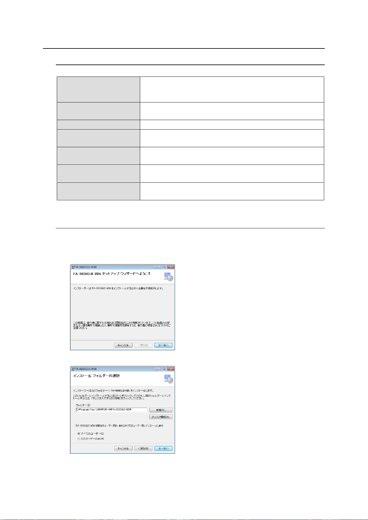
9. Windows GUI Setup
OS
Windows® 7 Professional SP1 (32/64bit)
Windows® 8.1,10 Pro (32/64bit)
(Mac OS is not supported.)
CPU
Intel® Core™ 2 Duo processor
2 GHz or higher
RAM
2 GB or more
Display
Resolution: 1280×1024 pixels or better recommended
Full color (24-bit) or more
Network port
Ethernet: More than 1 port
100BASE-TX/1000BASE-T
Network cable
100BASE-TX: Category 5 or higher
1000BASE-T: Category 5e or 6
Software
Microsoft® .NET Framework 4.6.2
Windows® Installer 3.1
9-1. System Requirements
To use the Windows GUI, your computer must meet the following requirements.
9-2. Installing Windows GUI Software
1. Open the CD-ROM, and the FA-9600GUI folder. Double-click the Setup icon to start the setup
wizard.
2. The following window will appear. Click Next (N).
3. Select the installation directory, then click Next.
74
Page 75
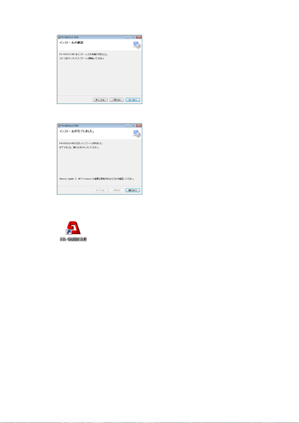
4. A confirmation screen will appear. Click Next to start the installation.
5. When installation is completed, the screen as shown below appears. Click Close to quit the
setup wizard.
6. Double-click the following icon on the desktop to start the Windows GUI.
75
Page 76
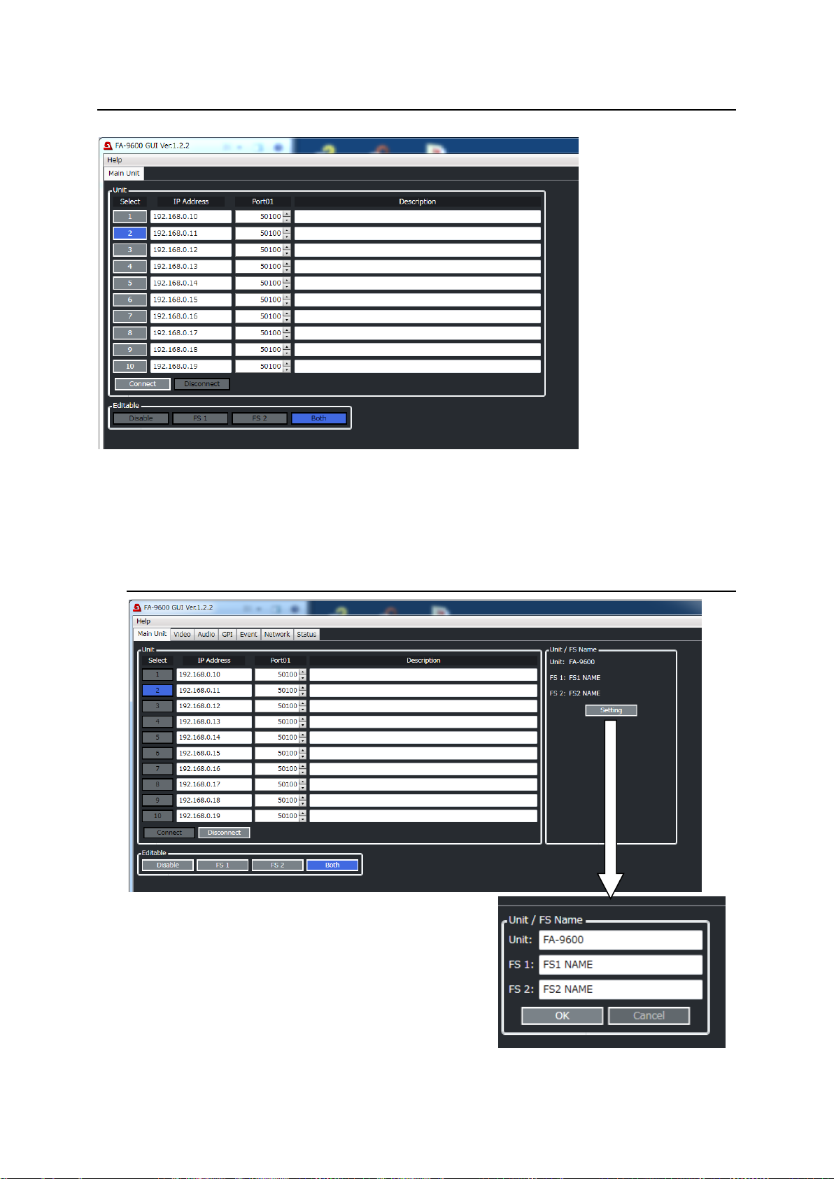
10. Windows GUI Control
When the Windows GUI starts, the following window will appear.
Enter the FA-9600 IP address and port number. Available up to 10 units.
Click the Unit Number under Select and click Connect to display the GUI screen. The Video tab screen
will open.
10-1. Main Unit Tab (Editable Setting, Name Change)
Editable Setting
Disable: Disables FS1 and FS2 relevant settings.
FS1: Enables only FS1 settings.
FS2: Enables only FS2 settings.
Both: Enables both FS1 and FS2 settings.
Unit and FS Name Change
Any names can be given to your FA-9600 unit and each FS.
To change names, click Setting to enter the setting mode.
76
Page 77
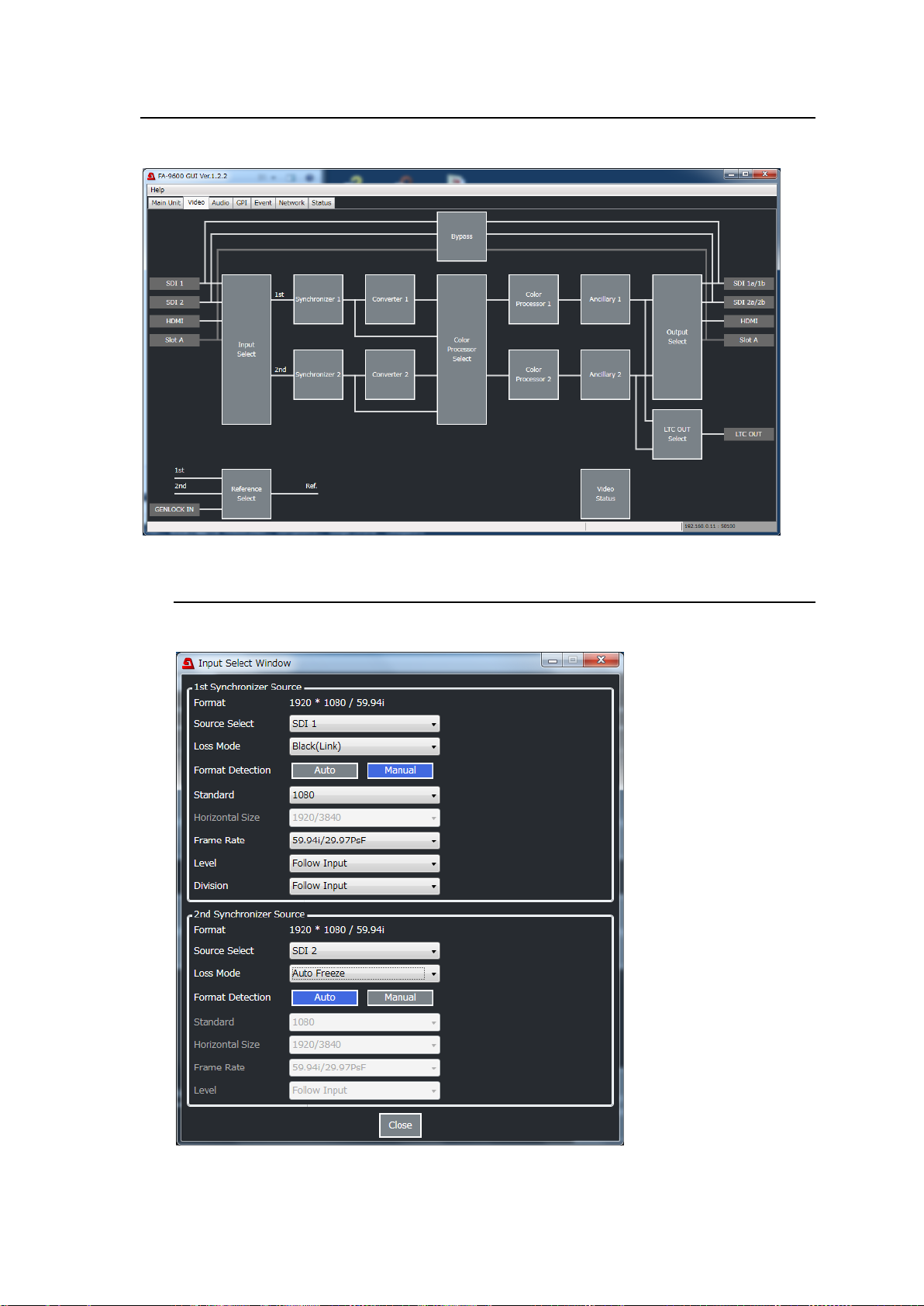
10-2. Video Tab Settings
Click the Video tab in the GUI screen to display the Video Block diagram as shown below.
10-2-1. Input Select
Click Input Select in the Video Block to display the following window.
Set the FS1 (1st Synchronizer) input in the Upper block and FS2 (2nd Synchronizer) input in
the Lower block.
77
Page 78
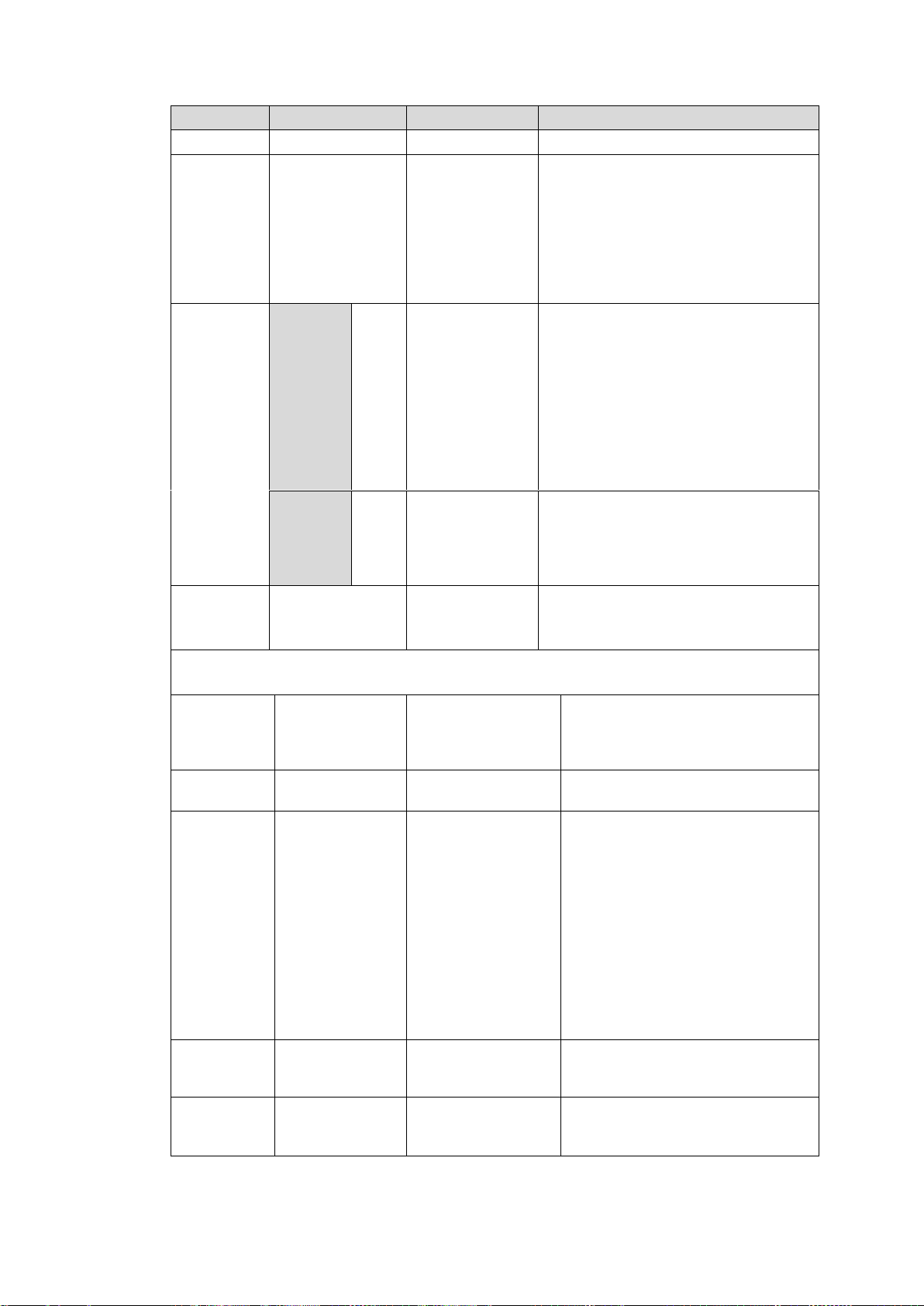
Item
Default
Setting range
Description
Format - -
Displays the detected input format.
Source
Select
SDI 1 (FS1)
SDI 2 (FS2)
SDI 1
SDI 2
HDMI
Slot A (SDI 1)
Slot A (SDI 2)
Slot A (SDI 3)
Slot A (SDI 4)
Slot A (SDI 1 - 4)
Selects a video signal input to FS1 or
FS2.
* Slot A (SDI 1) to Slot A (SDI 4)
are available when
FA-96EX3G44-R is installed into
Slot A.
* Slot A (SDI 1 - 4) is available only
on FS1
Loss Mode
W/o
FA-964K
(FS1/2)
Black
Black
Auto Freeze
Output Mute
Selects the output mode for input
signal loss.
Black: Outputs a black video.
Auto Freeze: Freezes and outputs the
last normal video.
Output Mute: Outputs no video signal
so that the FA-9600 downstream
device can detect video loss.
See <p 31> for partial loss of 4K Quad
input.
W/
FA-964K
(FS1)
Black
(Link)
Black(Link)
Black(Separate)
Auto Freeze
Output Mute
Black(Link): Outputs a black video.
Black(Separate): Output the input
video displaying black for the lost part.
See <p 31> for partial loss of 4K Quad
input.
Format
Detection
Auto
Auto
Manual
Specifies the FS output format.
Auto: FS input signal format.
Manual: Signal format specified below.
If Format Detection is set to Manual, specify the format using the following settings.
For supported video formats, see Sec. 13-1. “Specifications.”
Standard
1080
SD
720
1080
2160
Specifies the vertical image
resolution.(2160 available only on
FS1 and FA-964K required)
Horizontal
Size
1920/3840
1920/3840
(Not used)
Frame Rate
59.94i/ 29.97PsF
60p
59.94p
50p
30p
29.97p
25p
24p
23.98p
60i/30PsF
59.94i/29.97PsF
50i/25PsF
24PsF
23.98PsF
Specifies the frame / field rate.
Level
Follow Input
Follow Input
Level A
Level B(Dual Link)
Specifies the SDI mapping level.
Division
(FA-964K)
Follow Input
Follow Input
Square
2-Sample Interleave
Specifies the SDI image division
method. (FS1 only, FA-964K
required)
78
Page 79
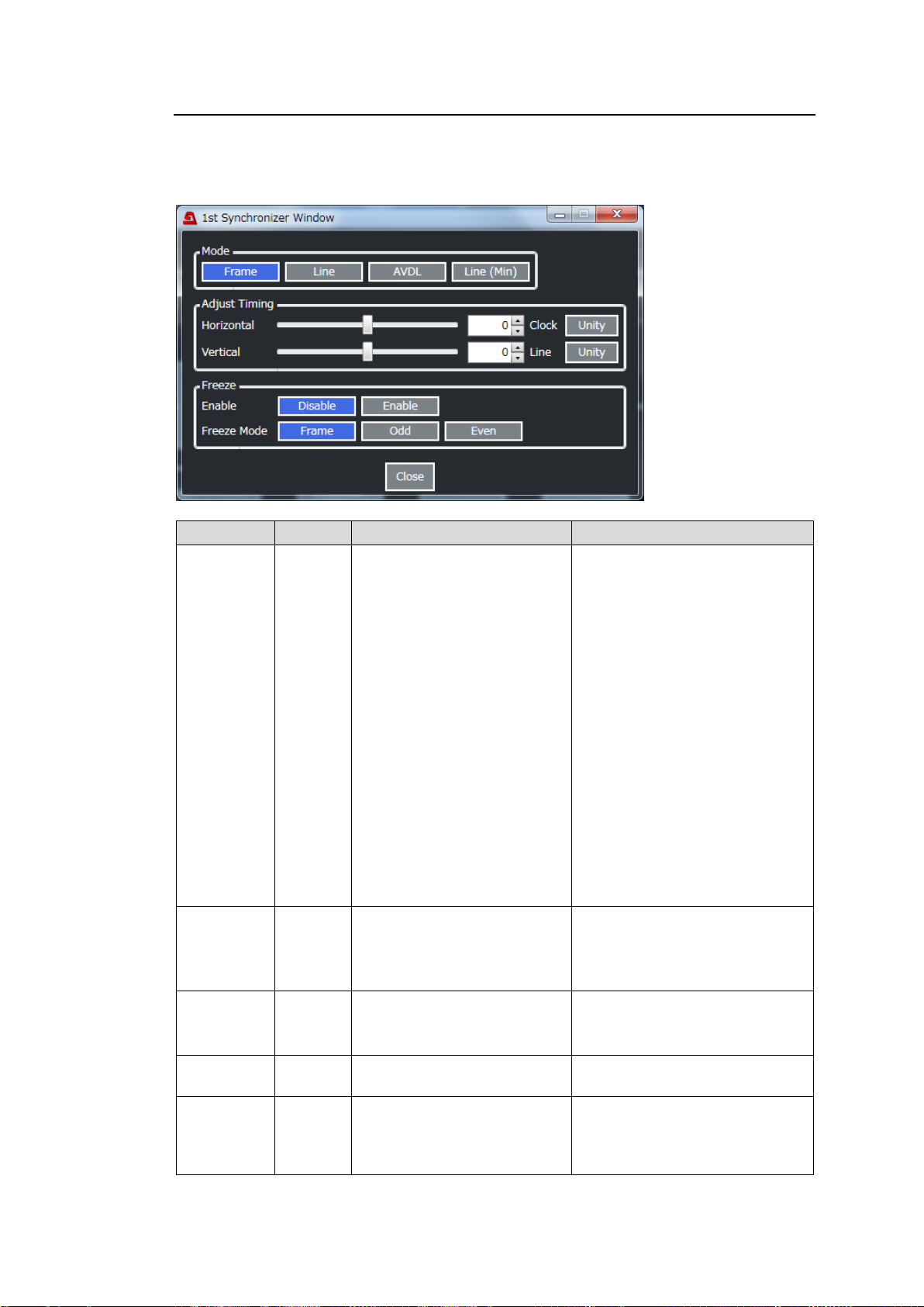
10-2-2. Synchronizer
Item
Default
Setting range
Description
Mode
Frame
Frame
Line
AVDL
Line(Min)
Selects the reference mode.
Frame: Horizontal and vertical
video signal adjustment referring
to genlock signal. Not necessary
for video input and genlock to
sync.
Line: ±1/2H horizontal video
signal adjustment output with 1H
delay. Synchronization
necessary for video input and
genlock signal.
AVDL: Horizontal video signal
adjustment output with 1H delay.
Synchronization necessary for
video input and genlock signal.
Line (Min): ±1/2H horizontal
video signal adjustment output
with minimum delay.
Synchronization necessary for
video input and genlock signal.
Adjust
Timing
(Horizontal)
0 Clock
-2750 to 2750 (1080/Level B)
-1375 to 1375 (1080)
-2063 to 2063 (720)
-864 to 864 (SD)
Sets the horizontal offset.
Adjust
Timing
(Vertical)
0 Line
-563 to 563 (1080)
-375 to 375 (720)
-313 to 313 (SD)
Sets the vertical offset.
Freeze
Enable
Disable
Disable
Enable
Turns freeze On/Off.
Freeze
Mode
Frame
Frame
Odd
Even
Sets the freeze mode.
This setting is ignored if
progressive/no signal is input to
FS.
Click Synchronizer, Timecode1 or Synchronizer, Timecode2 in the Video Block to display
the window as shown below.
If Synchronizer is selected:
79
Page 80
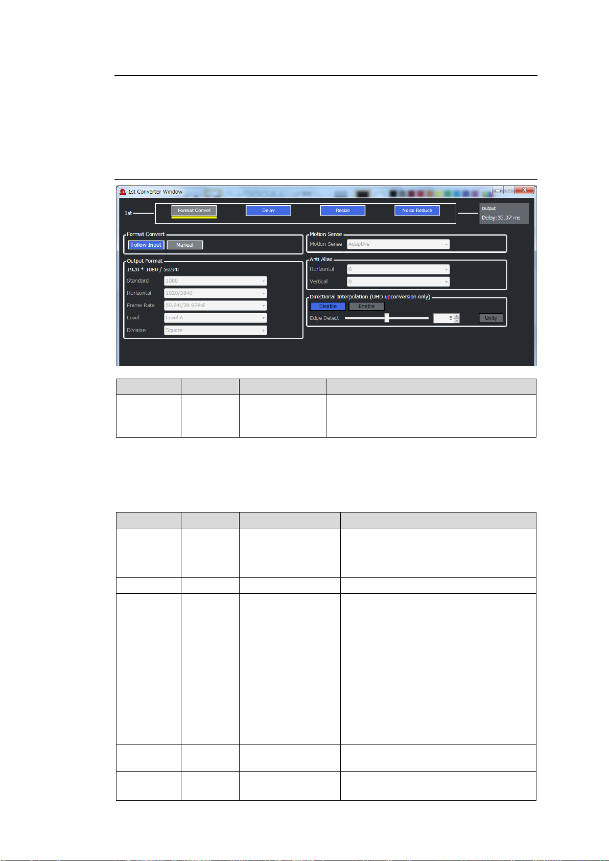
10-2-3. Converter 1, 2
Item
Default
Setting range
Description
Format
Convert
Follow
Input
Follow Input
Manual
Specifies the converter output format.
Follow Input: Converter input signal format
Manual: Signal format specified below.
Item
Default
Setting range
Description
Standard
1080
SD
720
1080
2160
Specifies the vertical image resolution.
(2160 available only on FS1 and
FA-964K required)
Horizontal - -
(Not used)
Frame Rate
59.94i/
29.97PsF
60p
59.94p
50p
30p
29.97p
25p
24p
23.98p
60i/30PsF
59.94i/29.97PsF
50i/25PsF
24PsF
23.98PsF
Specifies the frame/field rate.
Level
Level-A
Level-A
Level-B (Dual Link)
Selects the SDI mapping level.
Division
(FA-964K )
Square
Square
2-Sample Interleave
Selects the SDI image division method.
(FS1 only, FA-964K required)
Click Converter 1 or Converter 2 in the Video Block to display the window as shown below.
A converter flow will be displayed in the top. Click a block in the flow diagram to display the
detailed settings below. The selected block is underlined in yellow.
The converter total delay amount is displayed in the upper right corner of the screen.
10-2-3-1. If Format Convert Selected (FA-96UDC):
The following parameters are enabled when Format Convert is set to Manual.
Refer to Sec. 5-14-1. “Available Conversions on Converter 1 (FS1)” and Sec. 5-14-2.
“Available Conversions on Converter 2 (FS2)” for more details.
Output Format
80
Page 81
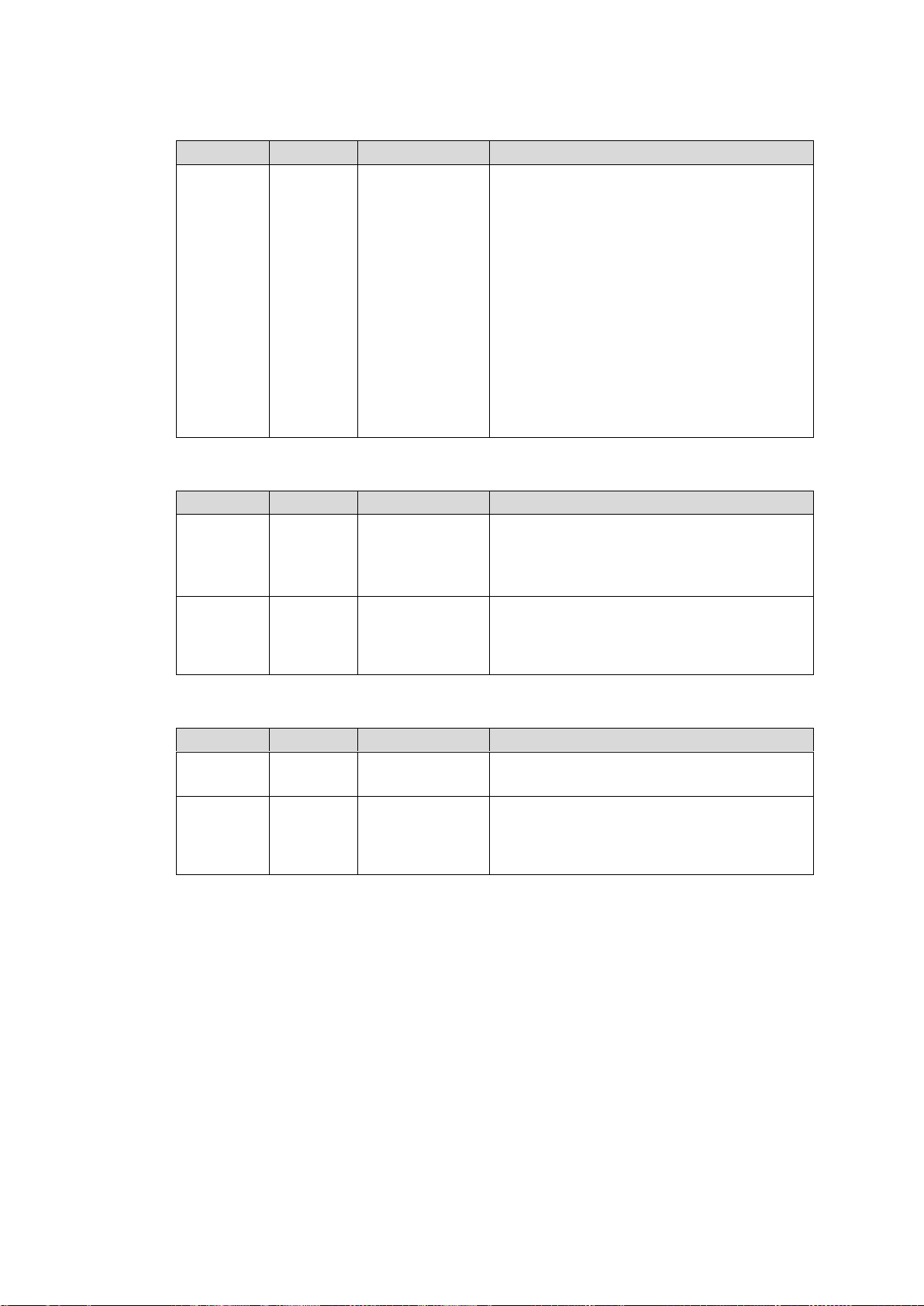
Item
Default
Setting range
Description
Motion
Sense
Adaptive
Adaptive
Field
Frame(Odd 1st)
Frame(Even 1st)
Field: Generates a progressive image from
one field of an interlaced image. The created
image has no motion artifacts, but vertical
resolution will be reduced.
Adaptive: Detects whether there is motion or
no motion in the scene, and generates an
optimal progressive image.
Frame(ODD 1st): Generates a progressive
image from two fields (odd and even) of an
interlaced image. Suitable for progressive
segmented frame input shot in progressive
format.
Frame(EVEN 1st): Generates a progressive
image from two fields (even and odd) of and
interlaced image.
Item
Default
Setting range
Description
Horizontal
0
Off
-7 to +8
Sets the horizontal anti-aliasing for the output
video image.
-7 to +8 (weak to strong)
Set to Off if no anti-aliasing is applied.
Vertical
0
Off
-7 to +8
Sets the vertical anti-aliasing for the output
video image.
-7 to +8 (weak to strong)
Set to Off if no anti-aliasing is applied.
Item
Default
Setting range
Description
Enable/
Disable
Enable
Disable
Enable
Enables/disables Edge Detect Level setting.
Edge
Detect
5
0 to 10
Sets Edge Detect Level.
The lower the value, the higher the detection
sensitivity, increasing the directional
interpolation area.
Motion Sense
Anti Alias
Directional Interpolation (for 4K up-conversion)
81
Page 82
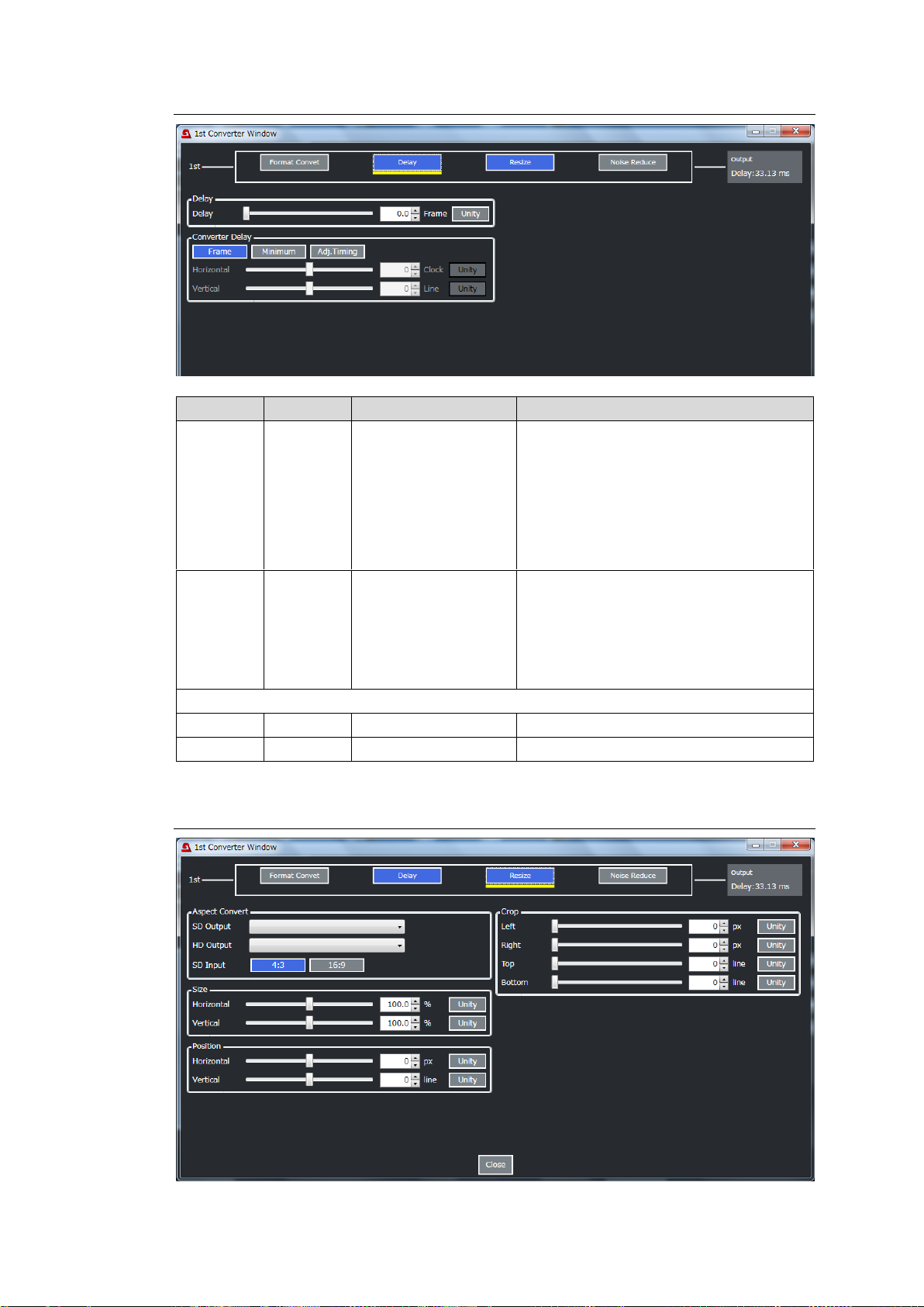
10-2-3-2. If Delay Selected
Item
Default
Setting range
Description
Delay
0.0
0.0-8.0
Allows you to add a delay in 0.5 frame
increments to the converter output.
As for 3G-Level B, 1080i and SD output
signals, delays can be added in 0.5 frame
increments for progressive signal input
and aspect ratio conversions, or in 1
frame increments in other cases.
Converter
Delay
Frame
Frame
Minimum
Adjustable
Sets the conversion delay mode.
Frame: Applies the delay set under
Delay.
Minimum: Applies the minimum delay.
Adjustable: Applies the adjustable delay
based on the Delay setting.
If Delay Mode is set to Adjustable, use the following parameters to adjust the output timing.
Horizontal
0 Clock
-2750 to 2750 Clock
Finely adjusts the horizontal timing.
Vertical
0 Line
-563 to 563 Line
Finely adjusts the vertical timing.
10-2-3-3. If Resize Selected (Converter 1 only)
82
Page 83
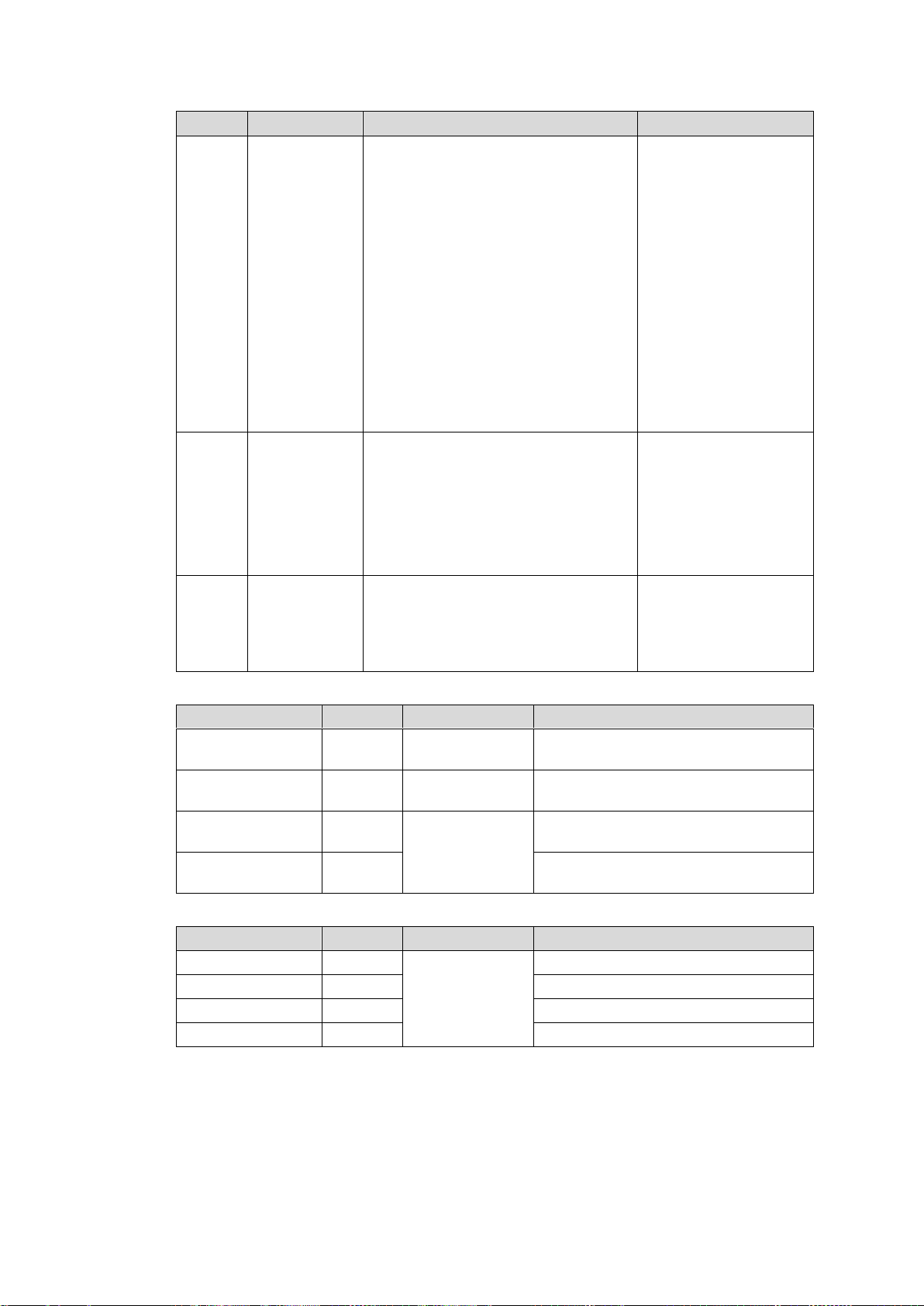
Aspect Convert
Item
Default
Setting range
Description
SD
Output
(4:3) Full
frame 4:3
(4:3) Letterbox 16:9 at top
(4:3) Letterbox 14:9 at top
(4:3) Letterbox greater than 16:9
(4:3) Full frame 4:3
(4:3) Letterbox 16:9 protected
(4:3) Letterbox 14:9
(4:3) Full frame 4:3 alternative 14:9
(4:3) Letterbox 16:9 alternative 14:9
(4:3) Letterbox 16:9 alternative 4:3
(16:9) Letterbox greater than 16:9
(16:9) Full frame 16:9
(16:9) Pillarbox 4:3
(16:9) Full frame protected
(16:9) Pillarbox 14:9
(16:9) Pillarbox 4:3 alternative 14:9
(16:9) Full frame 16:9 alternative 14:9
(16:9) Full frame 16:9 alternative 4:3
Sets the aspect ratio
when converting
HD-SDI to SD-SDI
signals.
HD
Output
(16:9) Full
frame 16:9
(16:9) Letterbox greater than 16:9
(16:9) Full frame 16:9
(16:9) Pillarbox 4:3
(16:9) Full frame protected
(16:9) Pillarbox 14:9
(16:9) Pillarbox 4:3 alternative 14:9
(16:9) Full frame 16:9 alternative 14:9
(16:9) Full frame 16:9 alternative 4:3
Sets the aspect ratio
when converting
SD-SDI to HD-SDI
signals.
SD
Input
4:3
4:3
16:9
Selects the SD input
aspect ratio.
If the input image is
horizontally squeezed,
set to 16:9.
Item
Default
Setting range
Description
Horizontal Size
100.0%
50.0 to 150.0%
Selects the horizontal image size ratio
after conversion.
Vertical Size
100.0%
50.0 to 150.0%
Selects the vertical image size ratio
after conversion.
Horizontal Position
0 Pixel
Varies
depending on
the signal
format.
Selects the horizontal image position
after conversion.
Vertical Position
0 Line
Selects the vertical image position
after conversion.
Item
Default
Setting range
Description
Left
0 Pixel
Varies
depending on
the signal
format.
Crops the image from the left side.
Right
0 Pixel
Crops the image from the right side.
Top
0 Line
Crops the image from the top.
Bottom
0 Line
Crops the image from the bottom.
Size/Position
Crop
83
Page 84
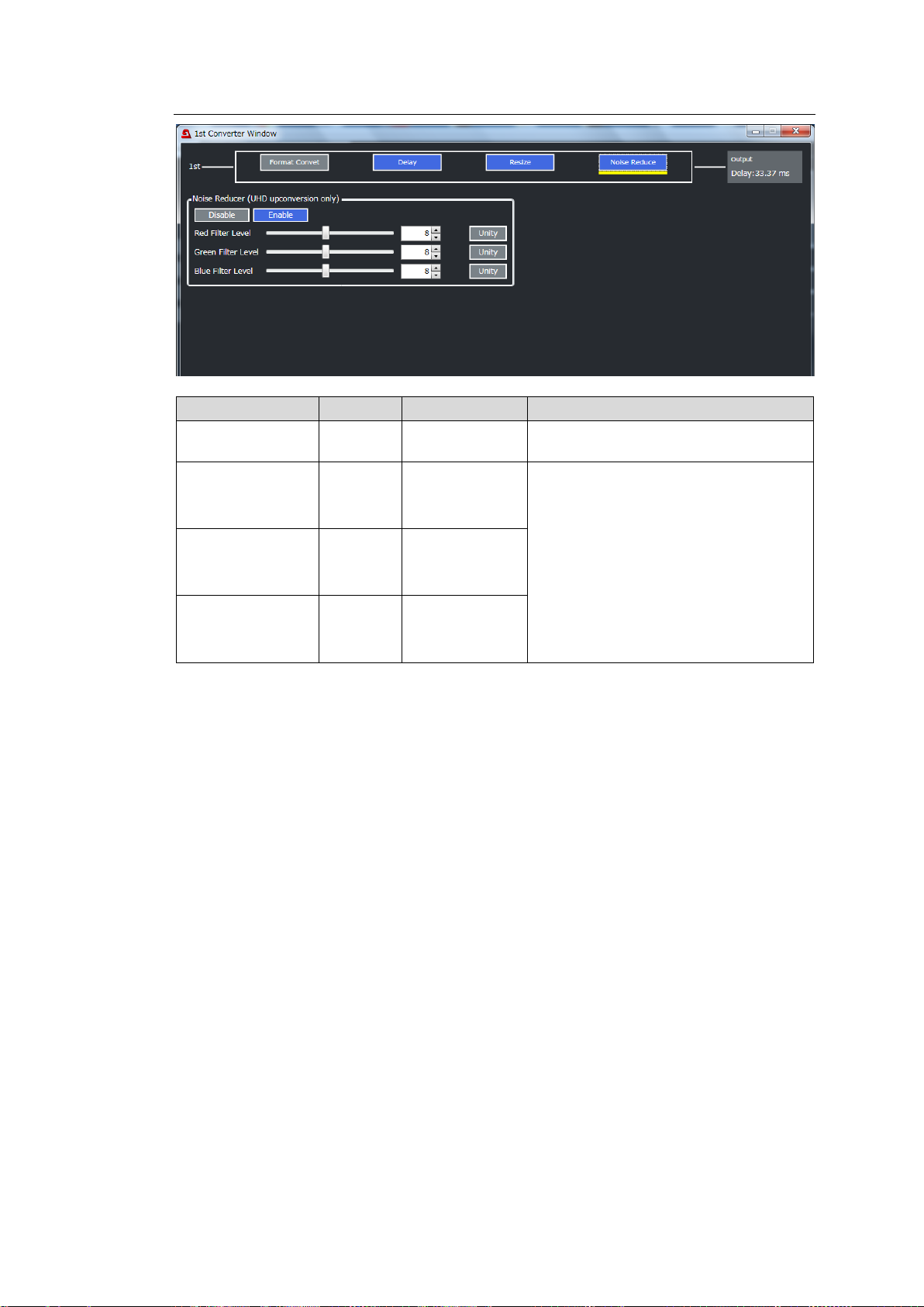
10-2-3-4. If Noise Reduce Selected (Converter 1 only)
Item
Default
Setting range
Description
Noise Reducer
Enable
Disable
Enable
Enables/disables Noise Reducer
applied for 4K up-conversions.
Red Filter Level
8
1-16
Sets the noise reduction level for low
luminance side (darker areas) in RGB.
Effective for camera lower random
noises.
Ineffective for noises in high luminance
side (brighter areas) or block noises
from compression.
The stronger (higher) the Red, Green,
Blue or Filter level, the fewer the
high-frequency components in video
images.
Green Filter Level
8
1-16
Blue Filter Level
8
1-16
84
Page 85
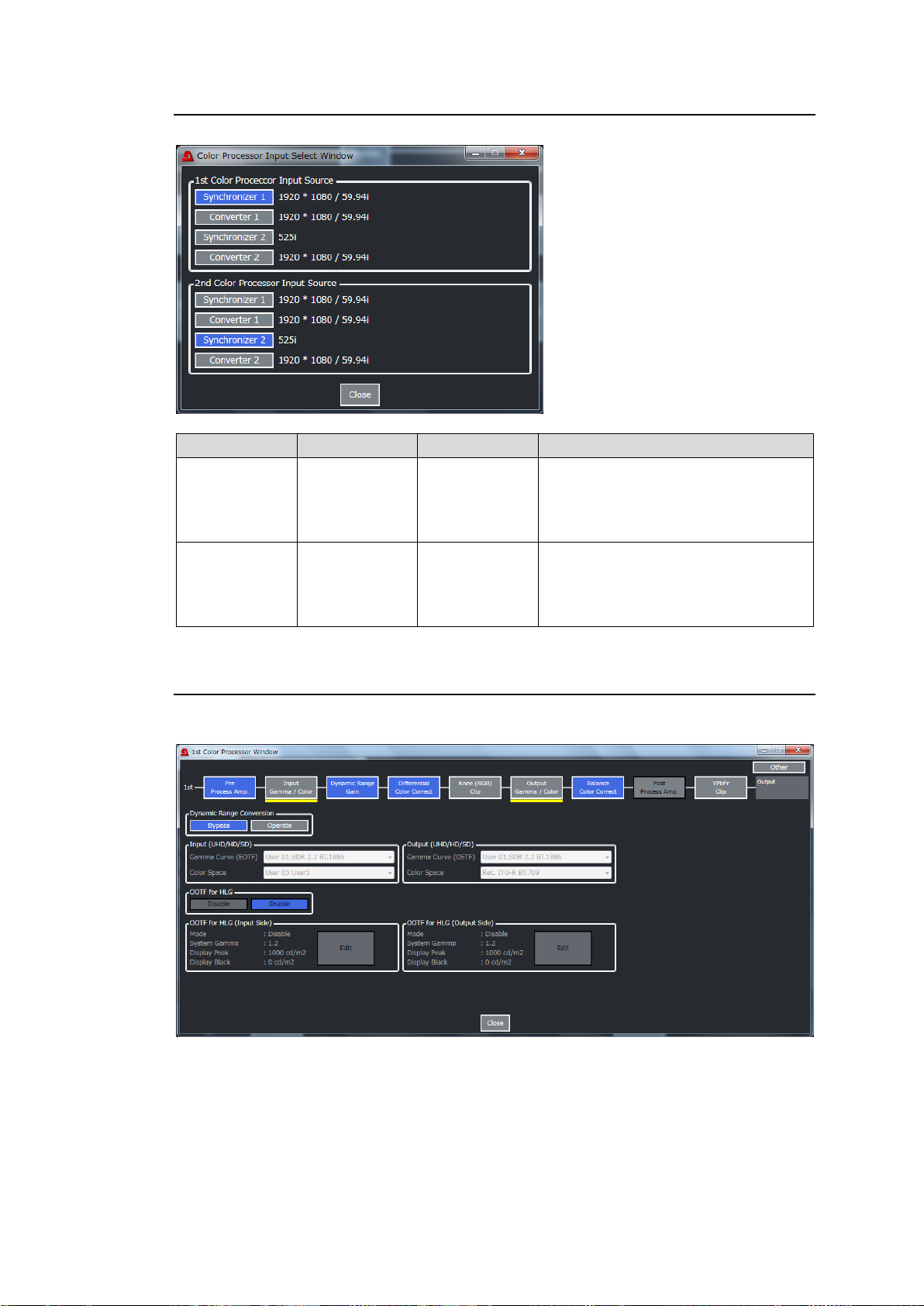
10-2-4. Color Processor Select
Item
Default
Setting range
Description
1st Color
Processor
Input Source
Synchronizer 1
Synchronizer 1
Converter 1
Synchronizer 2
Converter 2
Selects a source signal for FS1 Color
Processor.
2nd Color
Processor
Input Source
Synchronizer 2
Synchronizer 1
Converter 1
Synchronizer 2
Converter 2
Selects a source signal for FS2 Color
Processor.
Click Color Processor Select in the Video Block to display the windows as shown below.
10-2-5. Color Processor 1, 2
Click Color Processor 1 in or Color Processor 2 in the Video Block to display the windows
as shown below.
A color correction flow will be displayed in the top. Click a block in the flow diagram to display
the detailed settings below. The selected block is underlined in yellow.
85
Page 86
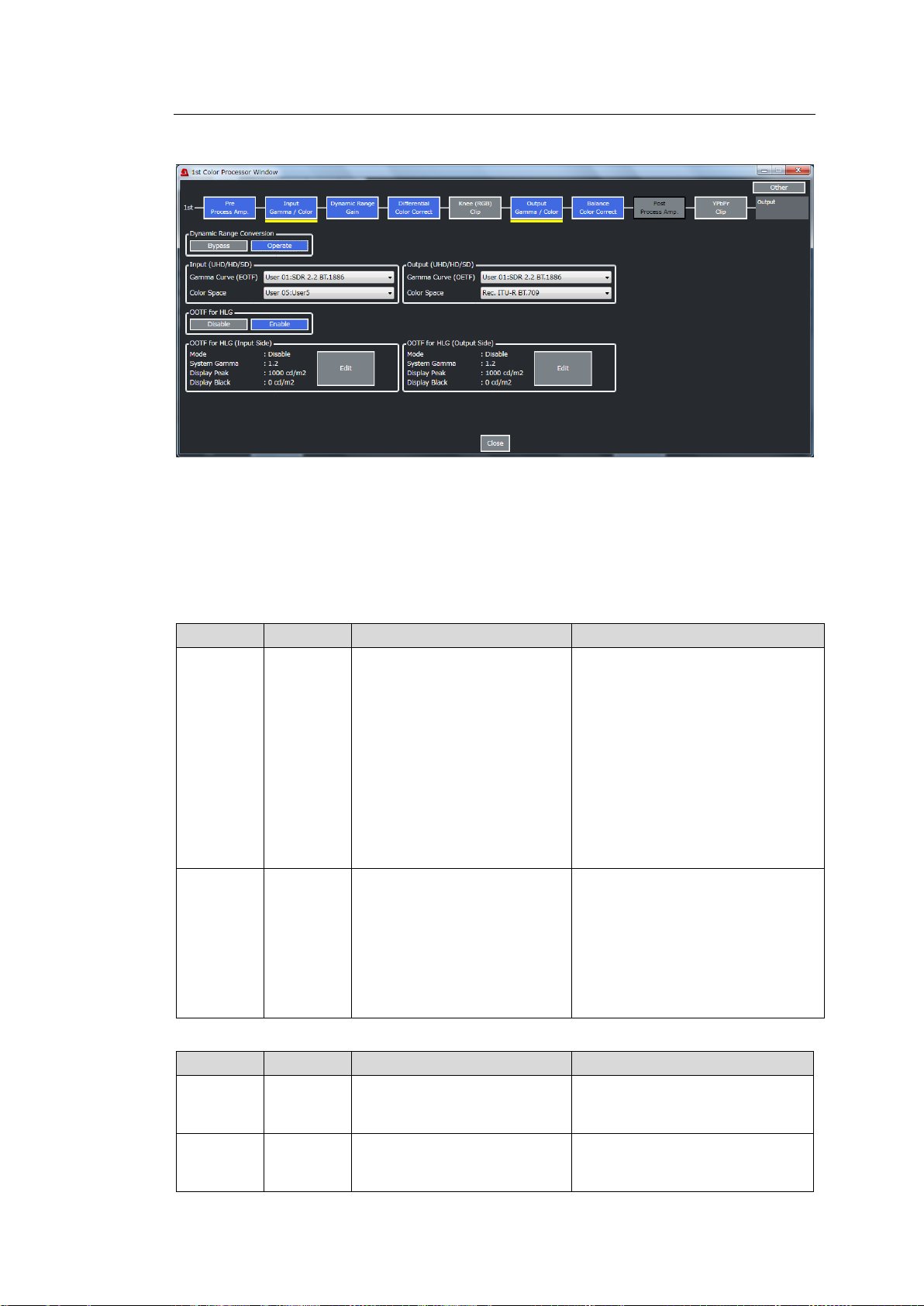
10-2-5-1. Input / Output Gamma / Color
Item
Default
Setting range
Description
Gamma
Curve
(EOTF)
User 01:
SDR 2.2
BT.1886
User 01: SDR 2.2 BT.1886
User 02: SDR 2.4 BT.1886
User 03: HLG BT.2100
User 04: HLG (RGB SG1.2)
User 05: HLG (RGB SG1.4)
User 06: ST 2084 (PQ)
User 07: SDR 2.2 BT.709
User 08: S-Log3
User 09: Canon Log 2
User 10: SDR 2.4 BT.1886
Selects a gamma curve for input.
(See GAMMA / COLOR Setting
Examples <p. 26>)
Gamma settings as shown at left
are respectively stored in files
named User 01 to User 10.
Gamma setting names and
content can be changed by editing
files in the Web GUI. (See Sec.
12-4 “Gamma Data.”)
These settings are shared by both
input and output gamma settings.
Color
Space
Rec.
ITU-R
BT.709
Rec. ITU-R BT.709
Rec. ITU-R BT.2020
User 01: S-Gamut/Gamut3
User 02
User 03
User 04
User 05
Selects a color space for input.
User 01-05 Gamut settings are
stored in files and these names
and content can be changed by
editint files in the Web GUI. (See
Sec. 12-5. “Gamut Data”)
These settings are shared by both
input and output gamut settings.
Item
Default
Setting range
Description
Gamma
Curve
(OETF)
User 01:
SDR 2.2
BT.1886
(Same as Input)
Selects a gamma curve for
output.
Color
Space
Rec.
ITU-R
BT.709
(Same as Input)
Selects the color space for output
Click Color Processor 1 or Color Processor 2 in the Video Block and select Input Gamma /
Color or Output Gamma / Color to display the window as shown below.
Dynamic Range Conversion
Enables/disables DRC (Dynamic Range Conversion). If setting to Bypass, the DRC process
is bypassed.
The following parameters are available when Dynamic Range Conversion is set to Operate.
Refer to the “GAMMA/COLOR Setting Examples” table <p 26> for setting details.
Input (UHD/HD/SD)
Output (UHD/HD/SD)
86
Page 87
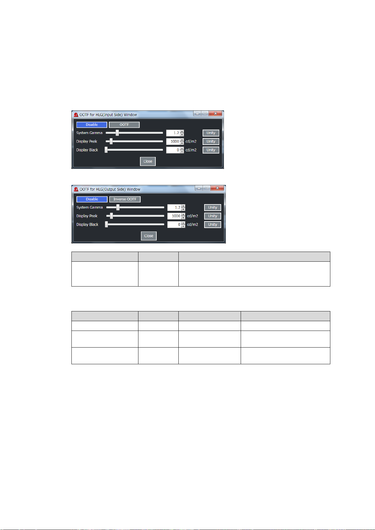
OOTF for HLG (Input Side/Output Side) (FA-96AHDR required)
Item
Default
Description
Disable button
OOTF button
Inverse OOTF button
Disable
Enables / disables OOFT or Inverse OOTF.
OOTF (for Input)
Inverse OOTF (for Output)
Item
Default
Setting range
Description
System Gamma
1.2
1.0 to 2.0
Sets the gamma value.
Display Peak
1000 cd/m2
100 to 10000 cd/m2
Sets the maximum luminance
peak for Display Light.
Display Black
0 cd/m2
0 to 100 cd/m2
Sets the minimum luminance
peak for Display Light.
Available only when HLG BT.2100 is set for Input / Output Gamma Curve. Set to Disable in
other cases.
Change OOTF for HLG to Enable and click Edit to set OOTF settings in the Input Side block
if Input Gamma Curve is set to HLG BT.2100 or in Output Side block if Output Gamma
Curve is set to HLG BT.2100. Refer to the “GAMMA/COLOR Setting Examples” table <p 26>
for setting details.
Input Side
Output Side
The following settings are available when OOTF or Inverse OOTF is enabled.
87
Page 88
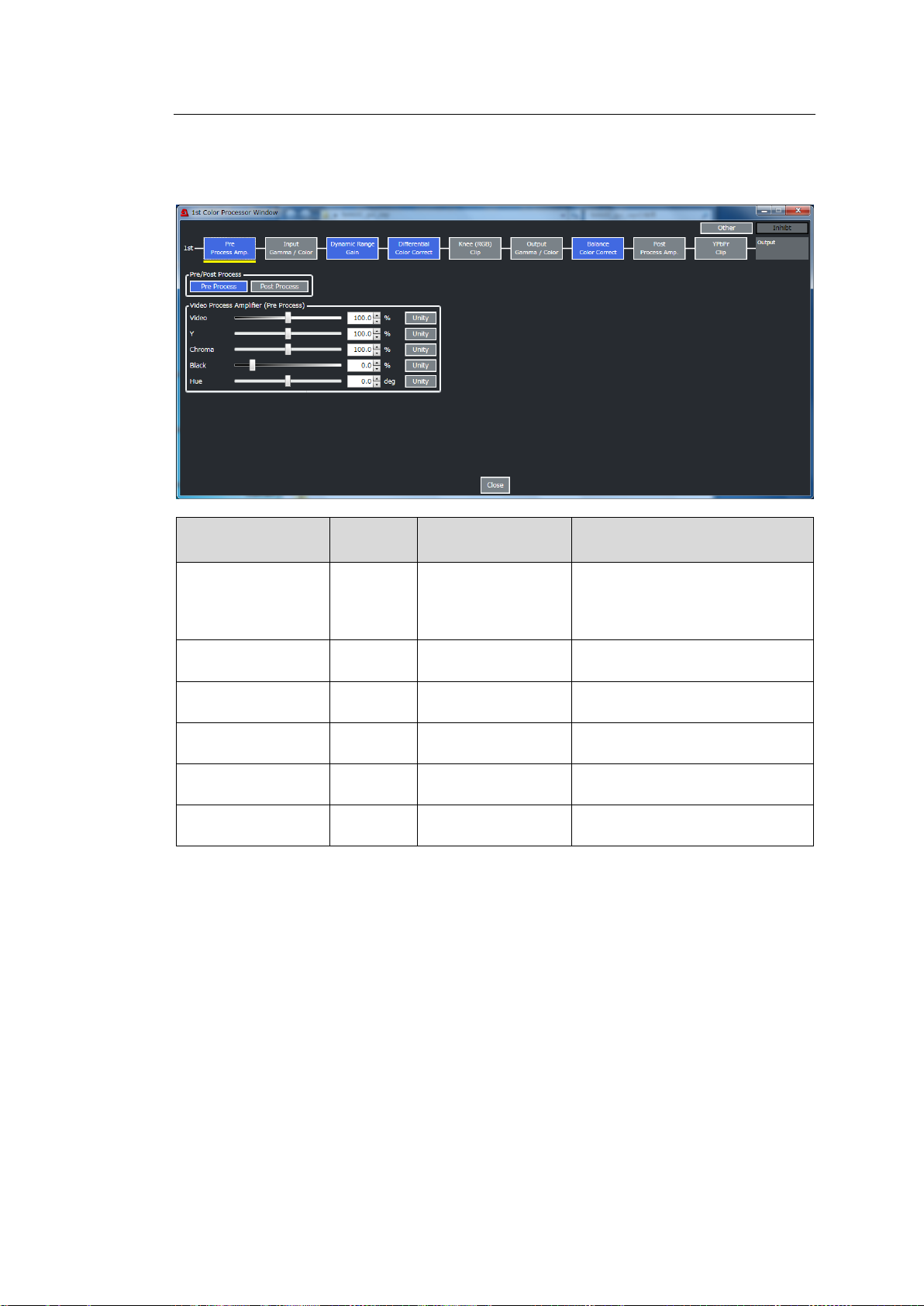
10-2-5-2. Pre Process Amp/Post Process Amp
Item
Default
Setting range
(Steps)
Description
Pre Process button
Post Process button
-
Pre Process
Post Process
Selects where the Proc Amp
process is located.
* Preprocess settings require
FA-96AHDR.
Video
100.0%
0.0 to 200.0%
(0.1%)
Adjusts the video level.
Y
100.0%
0.0 to 200.0%
(0.1%)
Adjusts the luminance level.
Chroma
100.0%
0.0 to 200.0%
(0.1%)
Adjusts the chrominance level.
Black
0.0%
-20.0 to 100.0%
(0.1%)
Adjusts the black level.
Hue
0.0deg.
-179.8 to 180.0deg.
(0.2 deg.)
Adjusts the chroma phase.
Click Color Processor1 or Color Processor 2 in the Video Block and select Pre Process
Amp. or Post Process Amp. to display the window as shown below.
* Post Process settings require the FA-96AHDR option.
88
Page 89
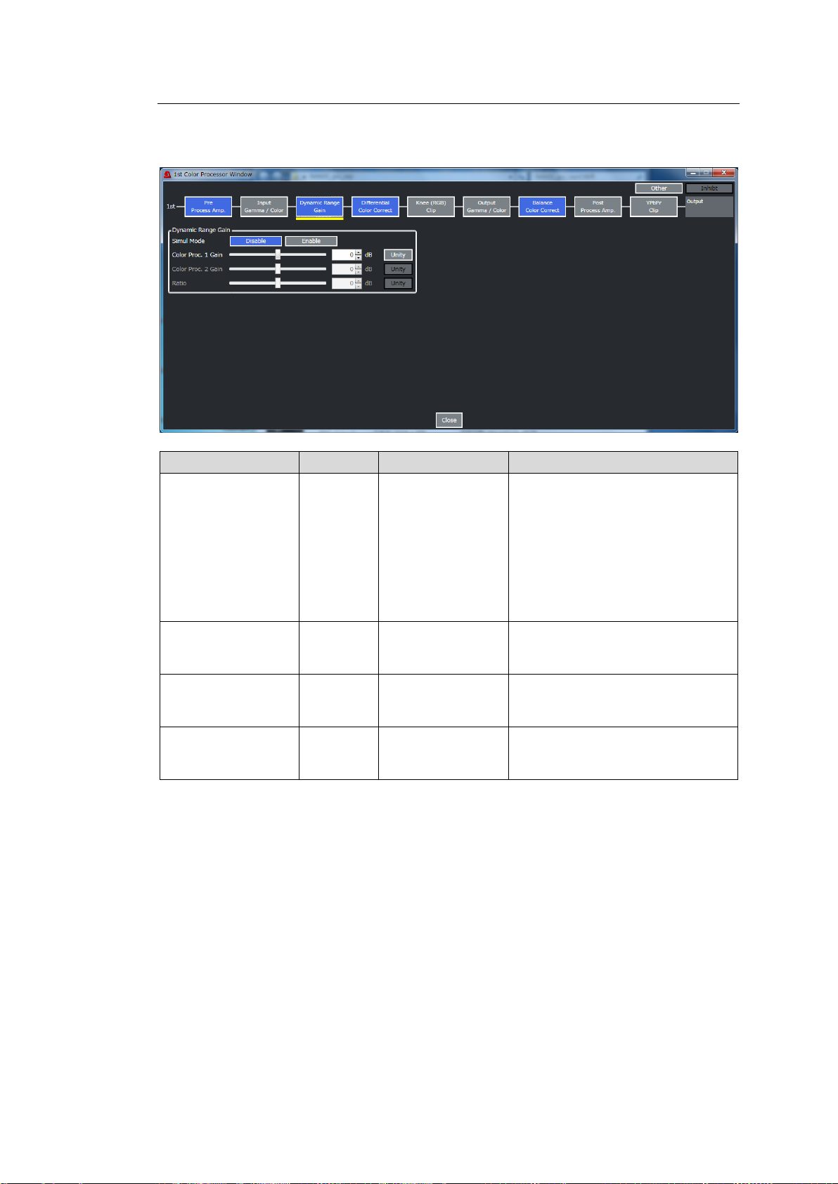
10-2-5-3. Dynamic Range Gain
Item
Default
Setting range
Description
Simul Mode
Disable
Disable
Enable
Sets whether to keep the gain
difference between Color
Processor 1 and 2.
Setting to Enable allows you to set
Gain, Color Correction
(Differential, Balance) and Clip
(RGB Clip, YPbPr Clip)
parameters by preserving the gain
difference set under Ratio below.
Color Proc.1 Gain
0 dB
-42dB to +42dB
Sets the gain for linear RGB signal
values that are EOTF-processed
on Color Processor 1.
Color Proc.2 Gain
0 dB
-42dB to +42dB
Sets the gain for linear RGB signal
values that are EOTF-processed
on Color Processor 2.
Ratio
0 dB
-24dB to +24dB
Sets the gain difference between
Color Processor 1 and 2.
(Processor 1 base)
Click Color Processor 1 or Color Processor 2 in the Video Block and select Dynamic
Range Gain to display the window as shown below.
89
Page 90
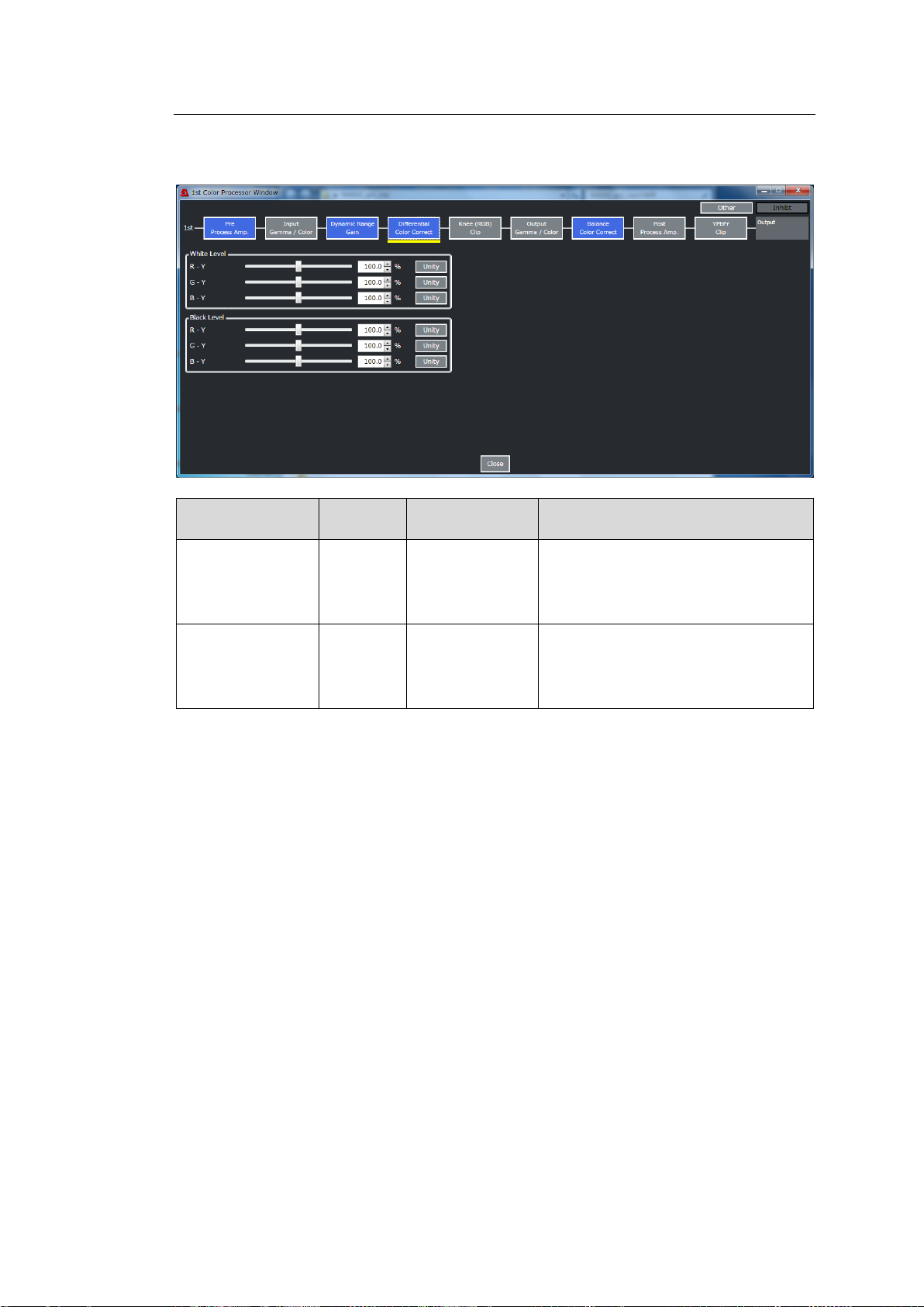
10-2-5-4. Differential Color Correct
Item
Default
Setting range
(Steps)
Description
White Level
(R-Y)
(G-Y)
(B-Y)
100.0%
0.0 to 200.0%
(0.5%)
Sets the white level by separately
adjusting R-Y, G-Y and B-Y
components.
Black Level
(R-Y)
(G-Y)
(B-Y)
100.0%
0.0 to 200.0%
(0.5%)
Sets the black level by separately
adjusting R-Y, G-Y and B-Y
components.
Click Color Processor 1 or Color Processor 2 in the Video Block and select Differential
Color Correct to display the window as shown below.
90
Page 91
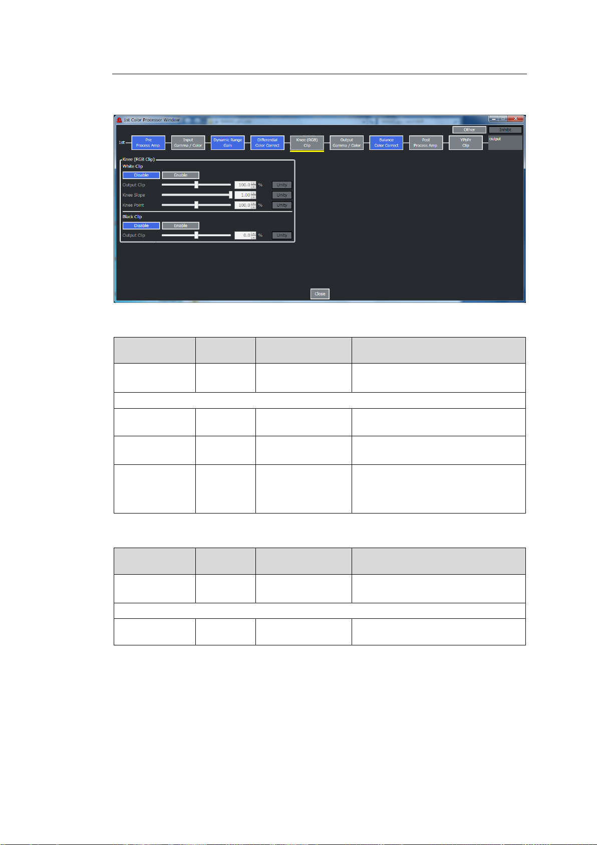
10-2-5-5. Knee (RGB) Clip
Item
Default
Setting range
(Steps)
Description
Disable /Enable
Disable
Disable
Enable
Enables/disables KNEE CLIP
(WHITE).
The following three parameters are available when White Clip is set to Enable.
Output Clip
100.0%
50.0 to 150.0%
(0.5%)
Sets the upper clip point in RGB color
space.
Knee Slope
1.0
0.1 to 1.0
(0.05)
Sets the knee clip slope clip in high
luminance areas.
Knee Point
(Variable)
50.0 to (Variable)
(0.5%)
Sets the knee clip start point in the
high luminance areas. Maximum and
default values vary depending on the
White Level (RGB white clip) setting.
Item
Default
Setting range
(Steps)
Description
Disable /Enable
Disable
Disable
Enable
Enables/disables Knee CLIP
(BLACK).
The following three parameters are available when Black Clip is set to Enable.
Output Clip
0.0%
-50.0 to 50.0%
(0.5%)
Sets the lower clip point in RGB color
space.
Click Color Processor 1 or Color Processor 2 in the Video Block and select Knee(RGB)
Clip to display the window as shown below.
White Clip
Black Clip
91
Page 92
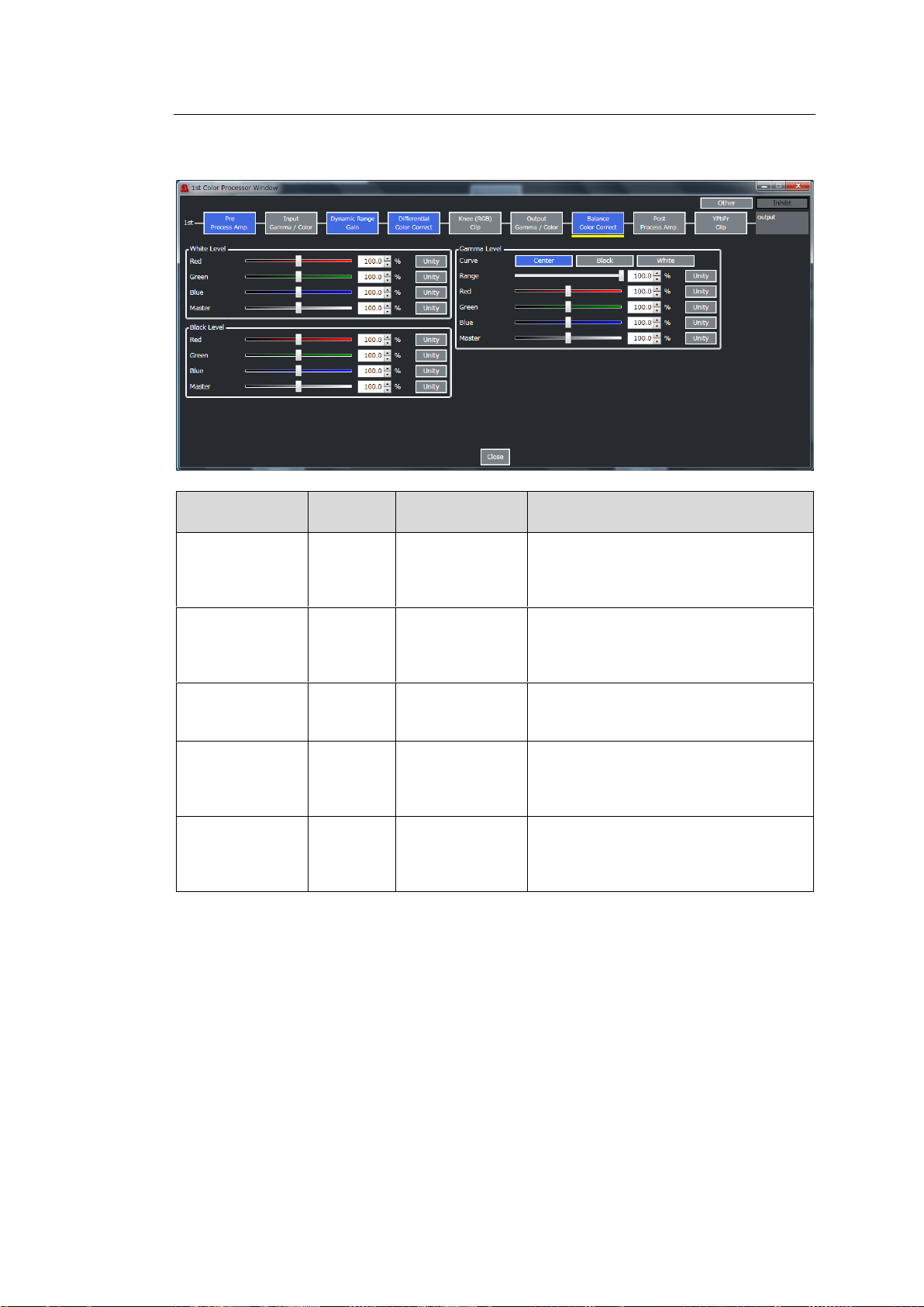
10-2-5-6. Balance Color Correct
Item
Default
Setting range
(Steps)
Description
White
Level(RGB)
100.0%
0.0 to 200.0%
(0.5%)
Sets the white level by separately
adjusting R, G, and B components or
simultaneously adjusting them using
Master.
Black
Level(RGB)
100.0%
0.0 to 200.0%
(0.5%)
Sets the black level by separately
adjusting R, G, and B components or
simultaneously adjusting them using
Master.
Gamma Curve
Center
Center
Black
White
Selects a gamma curve type.
Range
100.0%
0.5% to 100.0%
(0.5%)
Sets the upper threshold where the
gamma correction is enabled. A 100%
value is based on the OETF Maximum
Input.
Gamma
Level(RGB)
100.0%
0.0 to 200.0%
(0.5%)
Sets the gamma level by separately
adjusting R, G, and B components or
simultaneously adjusting them using
Master.
Click Color Processor 1 or Color Processor 2 in the Video Block and select Balance Color
Correct to display the window as shown below.
92
Page 93
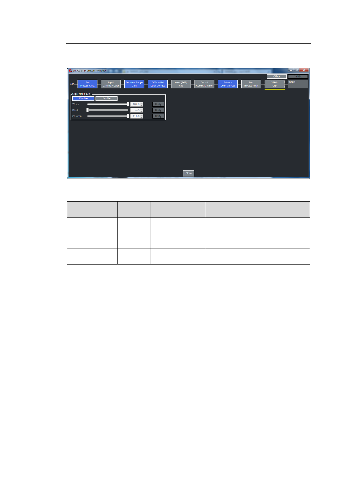
10-2-5-7. YPbPr Clip
Item
Default
Setting range
(Steps)
Description
White
109.0%
50.0 to 109.0%
(0.5%)
Sets the upper Y signal limit.
Black
-7.5%
-7.5 to 50.0%
(0.5%)
Sets the lower Y signal limit.
Chroma
111.0%
50.0 to 111.0%
(0.5%)
Sets the upper and lower PbPr signal
limits.
Click Color Processor 1 or Color Processor 2 in the Video Block and select YPbPr Clip to
display the window as shown below.
Use the Disable / Enable button to enable / disable YPbPr CLIP.
If enabled, the following parameters are available.
93
Page 94
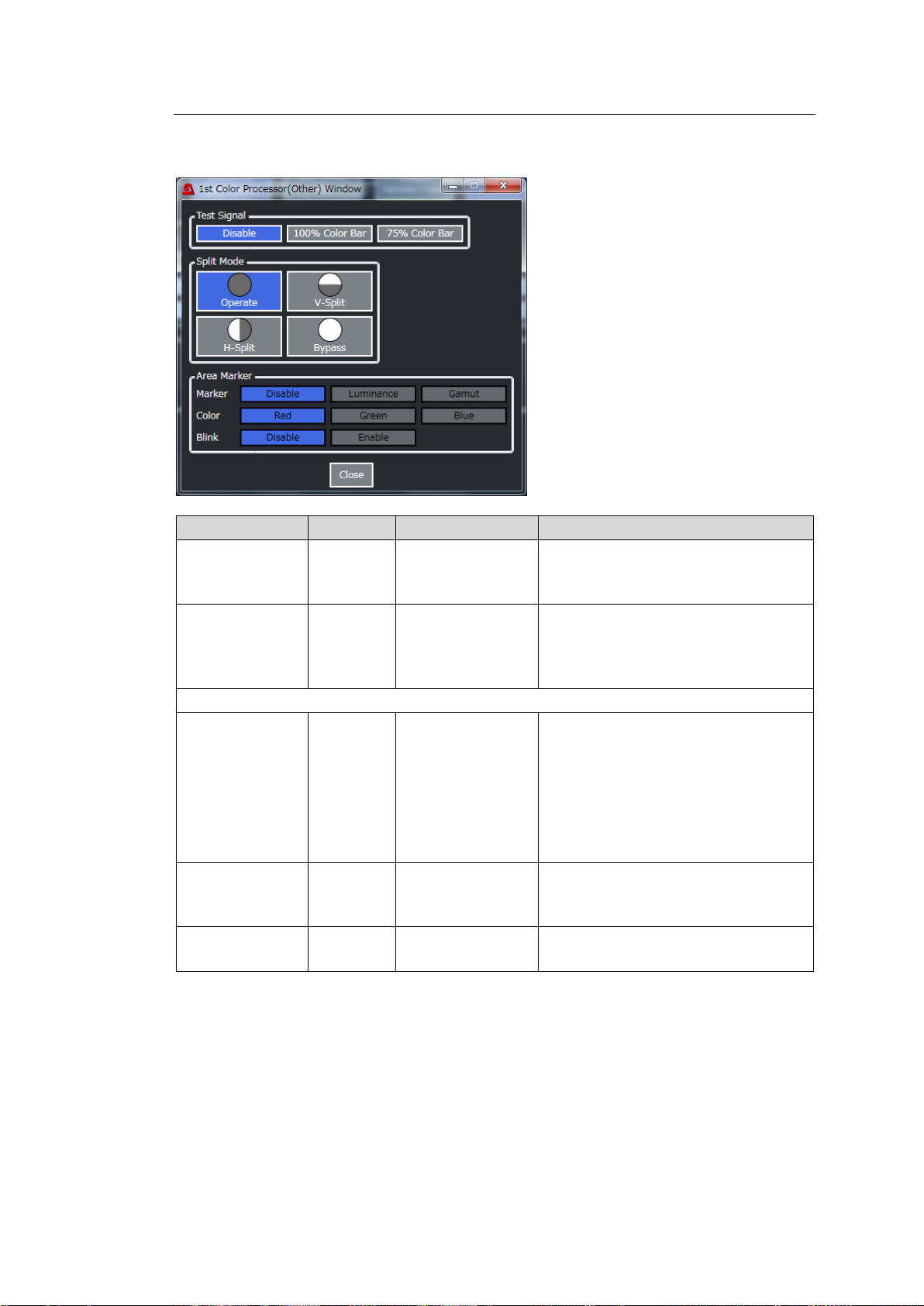
10-2-5-8. Other
Item
Default
Setting range
Description
Test Signal
Disable
Disable
100% Color Bar
75% Color Bar
Outputs the selected test signal.
Split Mode
Operate
Operate
V-Split
H-Split
Bypass
Selects the output image display
method.
The following settings require FA-96AHDR.
Marker
Disable
Disable
Luminance
Gamut
Selects the marker mode.
Disable: Plots no makers
Luminance: Marks pixels above the
high threshold when enabling RGB
Clip.
Gamut: Marks pixels whose RGB
values exceed the range between 0
and 1.0.
Color
Blink
Red
Green
Blue
Selects the marker color.
Blink
Disable
Disable
Enable
Toggles marker flashing on/off.
Click Color Processor 1 or Color Processor 2 in the Video Block and select Other to display
the window as shown below.
94
Page 95
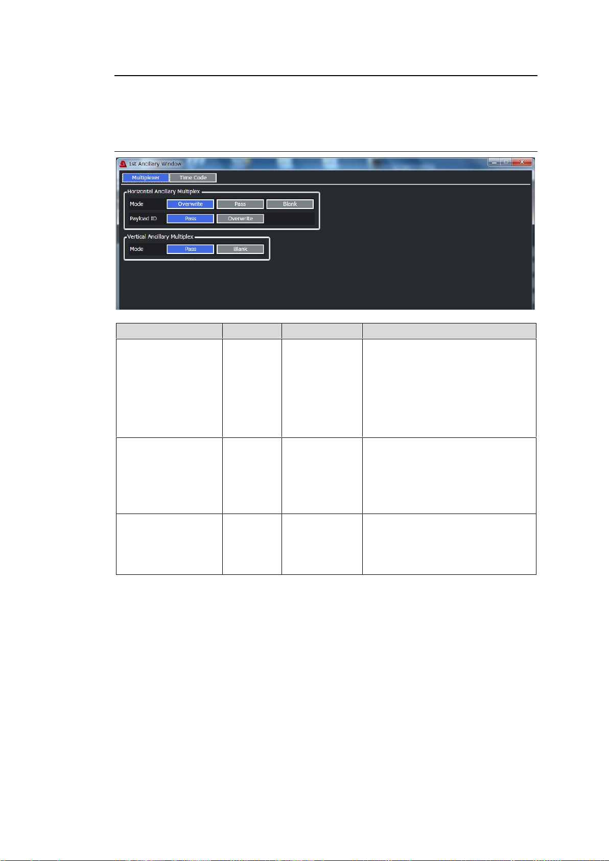
10-2-6. Ancillary 1/2
Item
Default
Setting range
Description
Horizontal Ancillary
Multiplex
Mode
Overwrite
Overwrite
Pass
Blank
Selects the H ANC data insertion
mode to each FS output.
Overwrite: Inserts the
internally-processed input H ANC
data.
Pass: Inserts the input H ANC data
without processing
Blank: Embeds no H ANC data.
Horizontal Ancillary
Multiplex
Payload ID
Overwrite
Pass
Overwrite
Selects the payload ID insertion
mode.
Pass: Inserts the input payload ID
without processing.
Overwrite: Inserts the payload ID of
internally-processed signal.
Vertical Ancillary
Multiplex
Mode
Pass
Pass
Blank
Selects the V ANC data insertion
mode to each FS output.
Pass: Inserts the input V ANC data
without processing.
Blank: Embeds no V ANC data.
Click Ancillary 1 or Ancillary 2 in the Video Block to display the window as shown below.
Switch the display by pressing Multiplexer or Time Code at the top of the window.
10-2-6-1. If Multiplexer Selected
95
Page 96
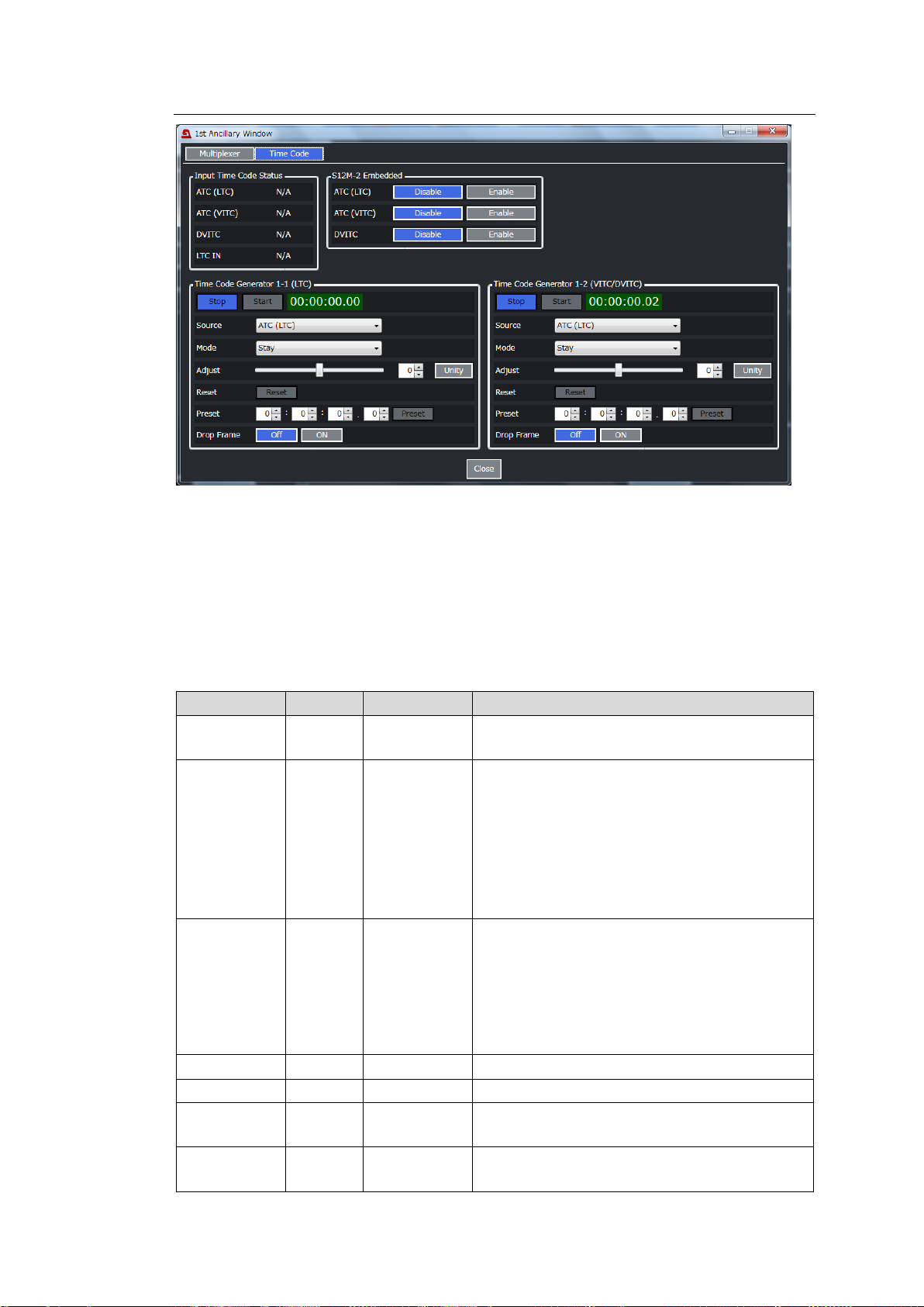
10-2-6-2. If Time Code Selected:
Item
Default
Setting range
Description
Start/Stop
button
-
-
Clicking Start starts the timecode.
Clicking Stop stops the timecode.
Source
ATC(LT
C)
ATC(LTC)
ATC(VITC)
DVITC
LTC IN
Generator
Selects the timecode source.
S12M-1 ATC(LTC): ATC(LTC) timecode in the
SDI input
S12M-1 ATC(VITC): ATC(VITC) timecode in
the SDI input
DVITC: DVITC timecode in the SD-SDI input
LTC IN: LTC input (FA-96DIN4-CBL required)
Generator: Generator’s timecode
Loss Mode
Stay
Stay
Continue
Disable
Selects the way to recover when a timecode
source loss is detected.
Stay: Stays outputting the last timecode.
Continue: Continues running with the timing
before loss.
Disable: Stops timecode output when the
source loss is detected.
Adjust
0
-16 to +16
Sets the offset from the source timecode.
Reset button
-
-
Resets the timecode.
Preset value
Preset button
-
-
Sets the timecode to the preset value.
Invalid input values are corrected.
Drop Frame
Off
Off
ON
Selects drop frame or non-drop frame timecode.
Input Time Code Status
Displays the timecode detection status in the SDI input.
◆ S12M-1 Embedded
Allows you to select whether to insert timecode (DVITC, ATC (LTC) and ATC (VITC) to the SDI
output on each FS.
Time Code Generator
Allows you to generate LTC (at left) or VITC/DVITC (at right) timecodes for output.
96
Page 97
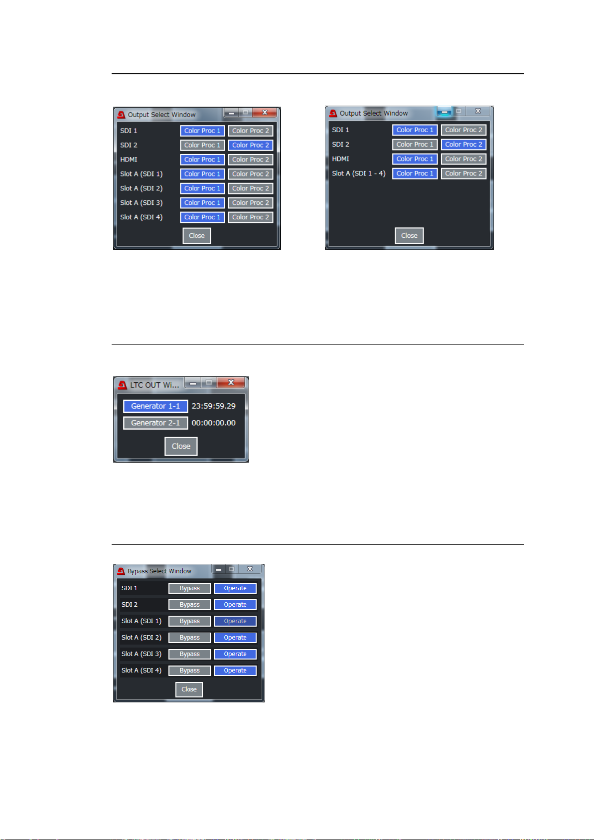
10-2-7. Output Select
Click Output Select in the Video Block to display the window as shown below.
If FA-96EX3G44-R installed If FA-96EX12G06 installed
Allows you to select a video image for each output.
* Slot A (SDI 1) to Slot A (SDI 4) require FA-96EX3G44-R or FA-96EX12G06.
10-2-8. LTC OUT Select (FA-96DIN4-CBL)
Click LTC OUT Select in the Video Block to display the window as shown below.
The LTC OUT on FA-96DIN4CBL outputs an internally generated timecode.
This menu selects which timecode generator to be used.
10-2-9. Bypass
Click Bypass in the Video Block to display the window as shown below.
Selecting Bypass passes input through to output without processing.
* Slot A (SDI 1) to Slot A (SDI 4) require FA-96EX3G44-R.
97
Page 98
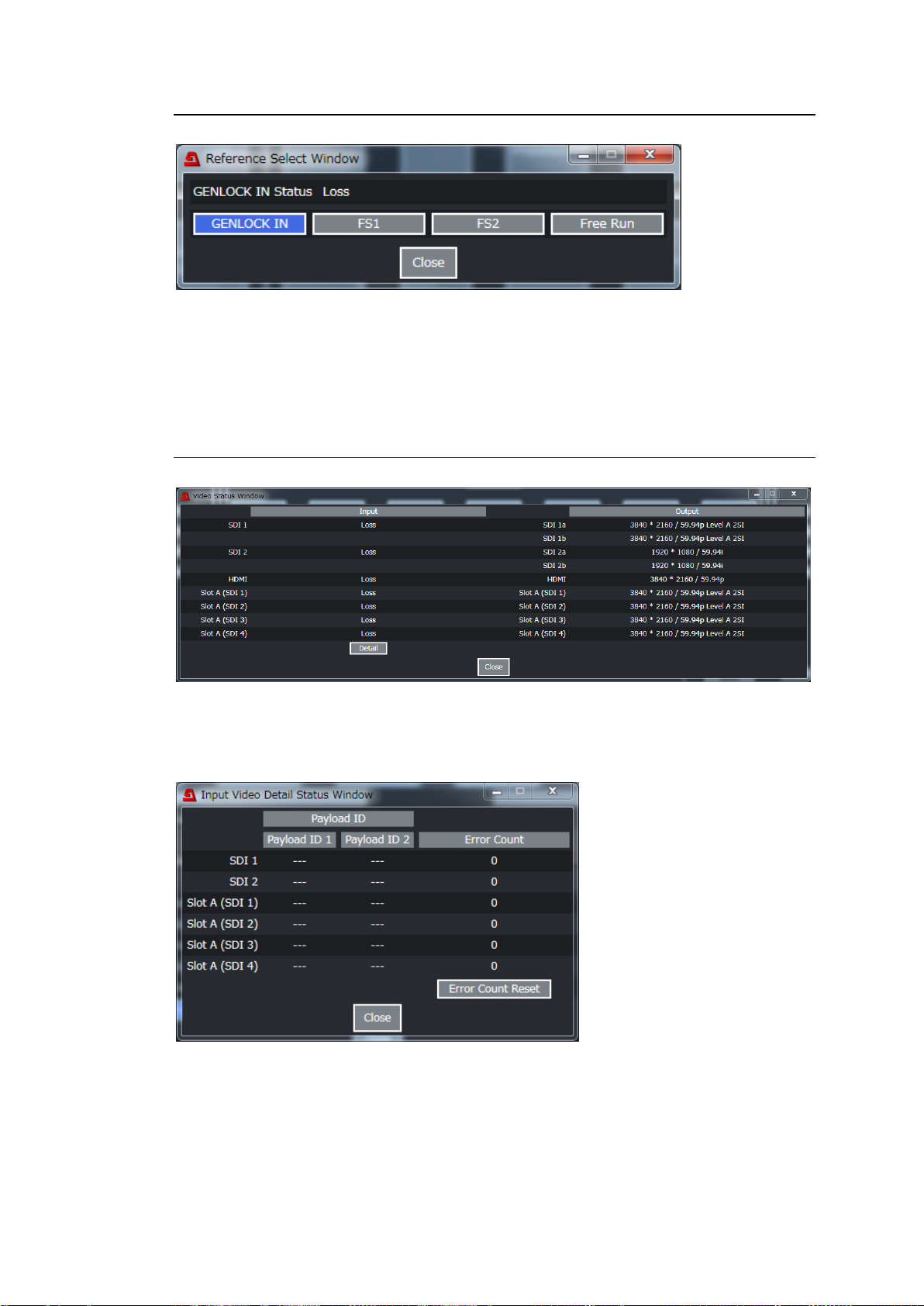
10-2-10. Reference Select
Click Reference Select in the Video Block to display the window as shown below.
Allows you to select the reference.
GENLOCK IN: External reference signal input to GENLOCK IN.
FS1, FS2: FS input signal selected under Input Select
Free Run: System clock
10-2-11. Video Status
Click Video Status in the Video Block to display the window as shown below.
In the above window, input signal status is displayed on the left side and output signal status
on the right side.
Clicking Detail pops up the window as shown below and displays the input payload ID
information and error counts. To reset error counts click Error Count Reset.
98
Page 99
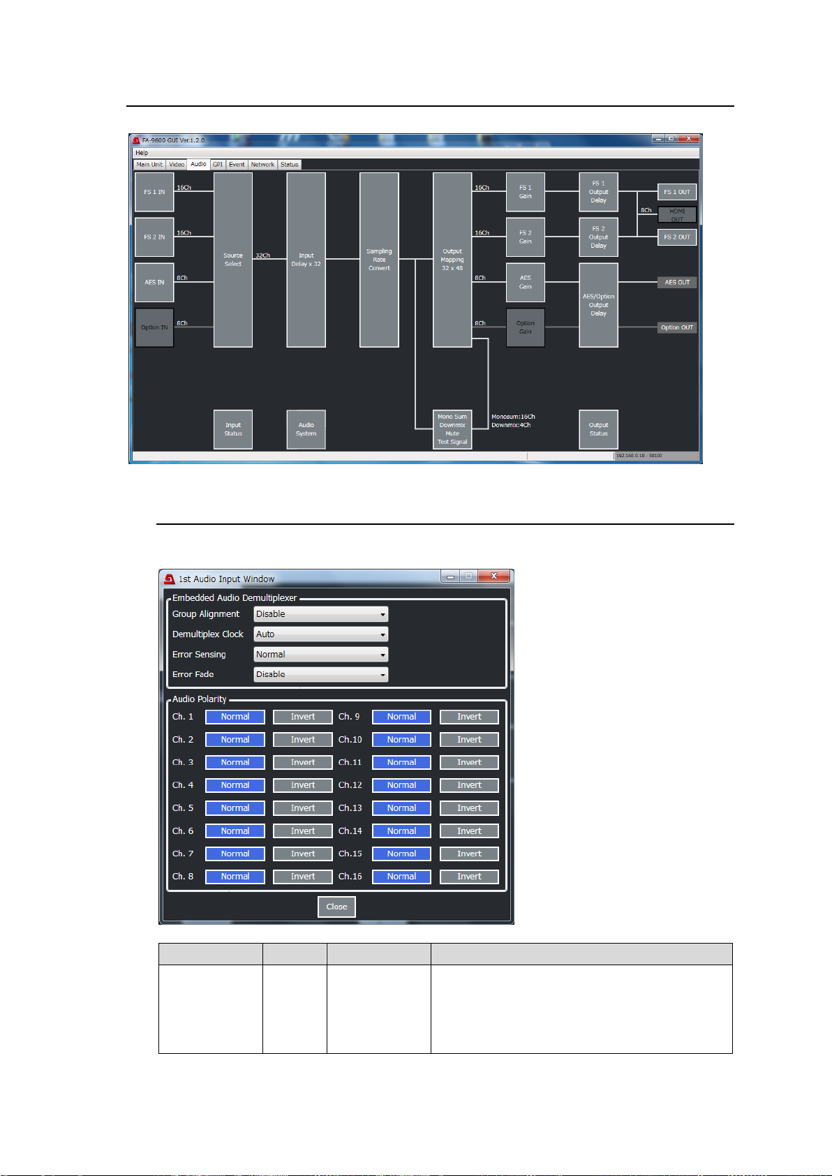
10-3. Audio Tab Settings
Item
Default
Setting range
Description
Group
Alignment
Disable
Enable
Disable
Selects whether to perform auto phase
adjustment among each SDI input audio group.
Enable: Performs auto adjustment.
Disable: Performs no auto adjustment (Normal
setting)
Click the Audio tab in the GUI screen to display the Audio Block diagram as shown below.
10-3-1. INPUT Block (FS 1/2 IN)
Click FS 1 IN or FS 2 IN in the Audio Block to display the following window.
99
Page 100
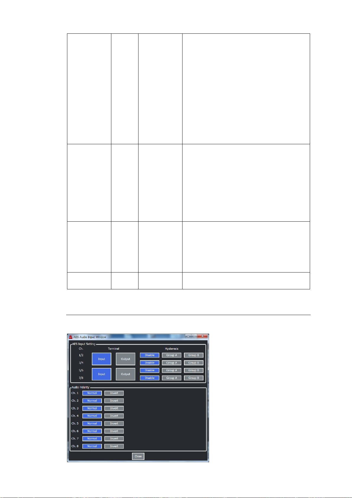
Demultiplex
Clock
Auto
Auto
Sync SDI
Audio Clock
Selects the audio de-embedding method for
SDI input.
Auto: Uses the audio clock phase data in the
SDI input to de-embed audio independently for
each group (Synchronous or asynchronous
de-embedding). If the audio phase data
incorrect or de-embedded audio has
noticeable jitter, audio channels in all groups
are de-embed synchronously.
Sync SDI: Synchronously de-embeds audio
channels in all groups without using the audio
clock phase data.
Audio Clock: Uses the audio clock phase data
in the SDI input to de-embed audio
independently for each group (Synchronous or
asynchronous de-embedding).
Error Sensing
Normal
Disable
Normal
Sensitive
Selects the input audio error detection mode
used for Error Fade above.
Disable: Detects no errors for Error Fade.
Normally do not use.
Normal: Detects SDI signal switching, ADP
(Audio Data Packet) change and DBN (Data
Block Number) switching as Error Fade errors.
Sensitive: Adds channel status change and
EDP (Extended Data Packet) change (SD-SDI
only) to those described above as Error Fade
errors.
Error Fade
Disable
Disable
Enable
Selects the way to handle output audio when
an error is detected in the input audio.
Disable: Passes through input audio without
using any effects.
Enable: Fades out and mutes audio when an
input error is detected and fades in when
recovered.
Audio Polarity
Ch.1 to 16
Normal
Normal
Invert
Selects the audio channel polarity.
10-3-2. INPUT Block (AES IN and Option IN)
Click AES IN or Option IN in the Audio Block to display the following window.
* Option IN requires FA-96AES-UBL.
100
 Loading...