

Page 1

OPERATION
MANUAL
FA-9520 (FA-9520 Mode)
Frame Synchronizer
FA-95PS
FA-95DACBL
FA-95AIO
FA-95CO
FA-95D-D/DE-E
FA-95ALA
FA-95RU
*
FA-10DCCRU*
3rd Edition - Rev. 5
SOFT Ver. 2.11 or higher
Page 2
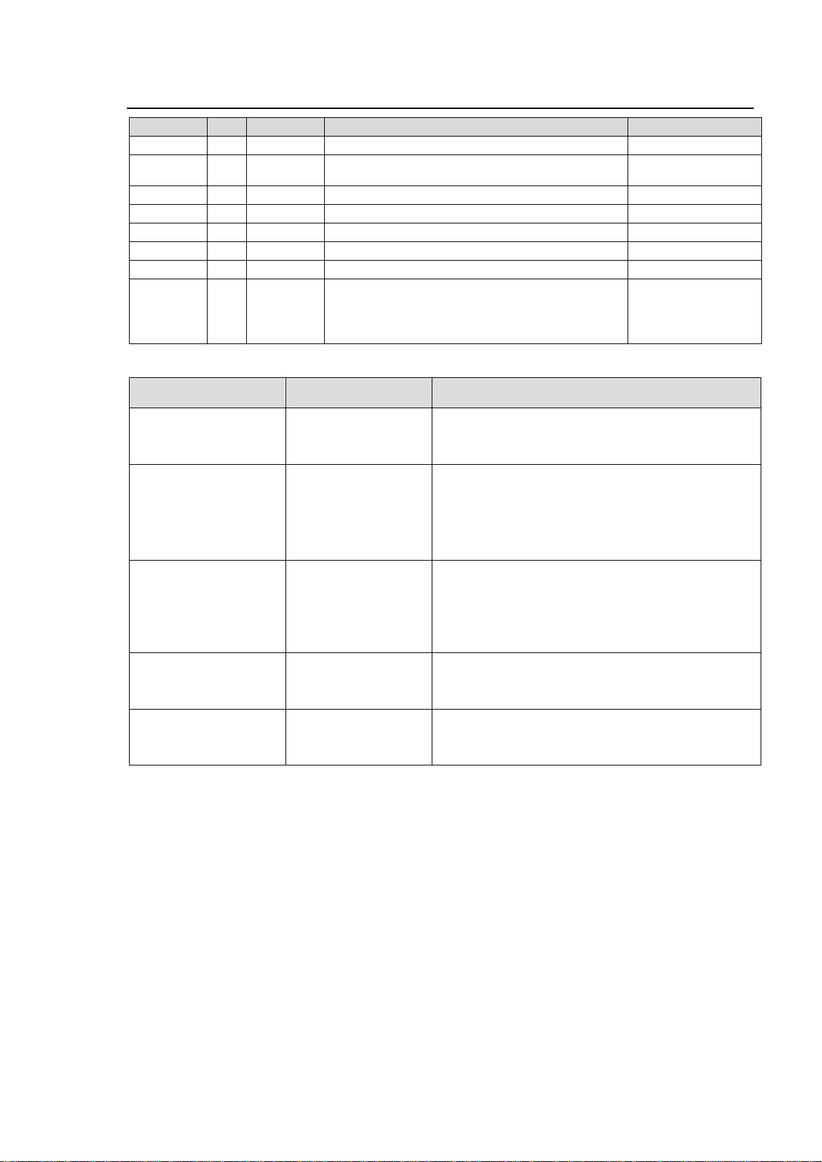
Edition Revision History
Edit.
Rev.
Date
Description
Where
1 2013/03/15
First edition (V0100)
2 2013/05/15
Added FA-95ALA, FA-95AIO, FA-95D-D/DE-E,
FA-95CO options and Auto Video Optimizer feature.
6-10-6, etc.
3 2013/05/31
Added FA-95RU option
3 1
2014/06/02
Corrected SNMP List
18 3 2
2014/07/08
Added FA-10DCCRU option.
7-3, 9-8-2, 24-1, etc
3 3 2015/11/12
Changes note on ancillary data
5-7-5
3 4 2016/03/25
Added new SNMP MIB objects.
18
3 5 2017/07/27
Updated downmixing function.
Added notes.
Changed items not stored in event memory.
Deleted the index.
6-7, 6-8, 9-3-9
6-10-2-1, 6-10-2-2
8-4
Version *1
Supported
Feature/Option
Note
FPGA1: 1.00 or higher
FPGA2: 1.00 or higher
FPGA3: 1.00 or higher
SOFT: 1.00 or higher
FA-95PS
FA-95DACBL
First edition
FPGA1:1.10 or higher
FPGA2:1.10 or higher
FPGA3:1.00 or higher
SOFT:1.10 or higher
FA-95ALA
FA-95AIO
(FA-95AVO)
FA-95D-D
FA-95DE-E
FA-95CO
Supports FA-95ALA, FA-95AIO, FA-95DE/DE-E,
FA-95CO options and Auto Video Optimizer feature.
FA-95D-D and FA-95DE-E communication methods with
the main unit modified to support FA-95ALA.
Supported FA-95D-D/FA-95DE-E versions:
FPGA1: 1.00
FPGA2: 2.00 (1.10 or lower is inoperative in this unit.)
FPGA1:1.10 or higher
FPGA2:1.10 or higher
FPGA3:1.00 or higher
SOFT:2.00 or higher
FA-95RU
Modified FA-95RU to add FA-9520 support
FA-95RU Ver. 6.00 or higher-compatible
Added BY-PASS function to FA-95AIO GPI
Added option slot change warning feature
Enhanced FA-95ALA measurement accuracy
FPGA1: 1.00
FPGA2: 1.10
FPGA1: 1.12 or higher
FPGA2: 1.10 or higher
FPGA3: 1.00 or higher
SOFT: 2.03 or higher
FA-10DCCRU
Modified FA-10DCCRU to add FA-9520 support
FA-10DCCRU SOFT Ver. 1.00, FPGA1/2 Ver 1.00 or
higher-compatible
FPGA1: 1.12 or higher
FPGA2: 1.10 or higher
FPGA3: 1.00 or higher
SOFT: 2.10 or higher
SNMP feature
Added new SNMP MIB objects on Process, CC,
Converter, Video and Audio systems.
Software Versions and Supported Options
*1 Version information can be seen as described in section 7-8 “UNIT Ver.”.
2
Page 3
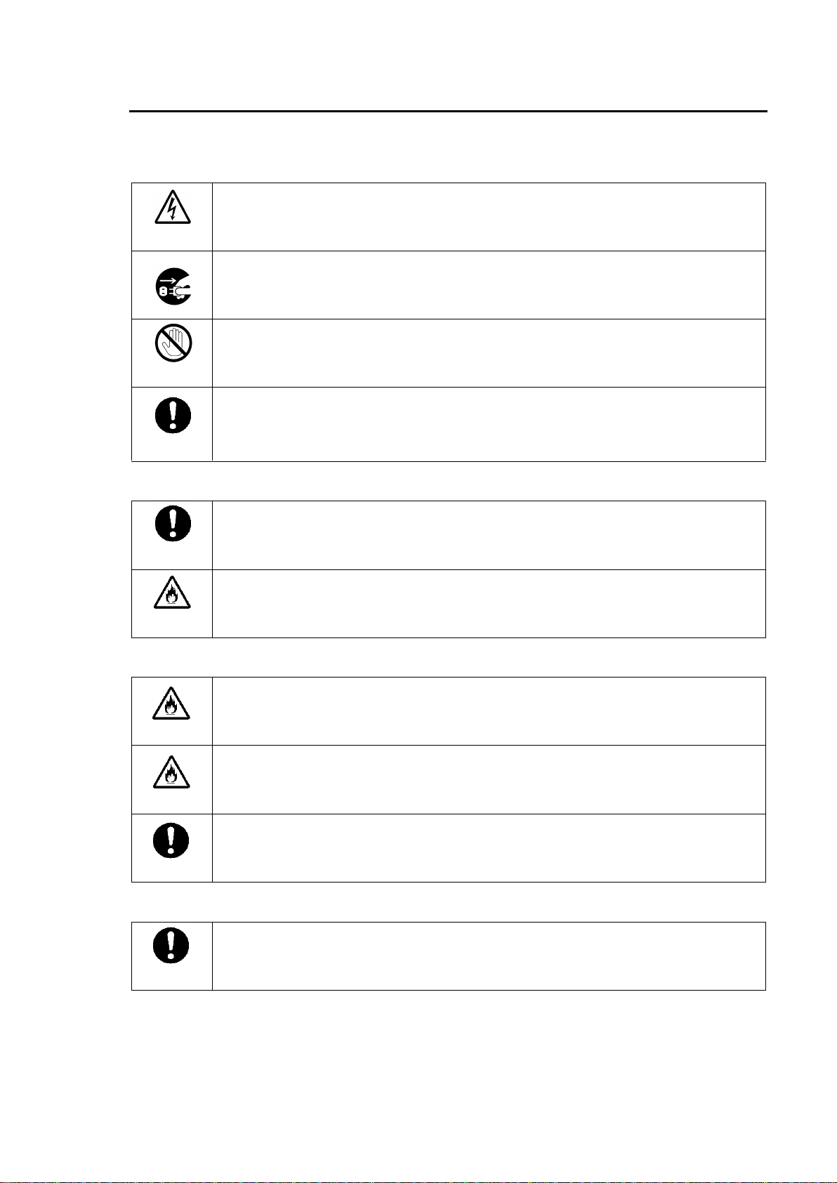
Precautions
Operate unit only on the specified supply voltage.
Disconnect power cord by connector only. Do not pull on cable portion.
Do not place or drop heavy or sharp-edged objects on power cord. A damaged cord
can cause fire or electrical shock hazards. Regularly check power cord for
excessive wear or damage to avoid possible fire / electrical hazards.
Ensure power cord is firmly plugged into AC outlet.
Ensure unit is properly grounded at all times to prevent electrical shock hazard.
Do not ground the unit to gas lines, units, or fixtures of an explosive or dangerous
nature.
Do not operate unit in hazardous or potentially explosive atmospheres. Doing so
could result in fire, explosion, or other dangerous results.
Do not allow liquids, metal pieces, or other foreign materials to enter the unit. Doing
so could result in fire, other hazards, or unit malfunction.
If foreign material does enter the unit, turn power off and disconnect power cord
immediately. Remove material and contact authorized service representative if
damage has occurred.
Handle with care to avoid shocks in transit. Shocks may cause malfunction. When
you need to transport the unit, use the original packing materials or alternate
adequate packing.
Stop
Caution
Caution
Caution
Hazard
Hazard
Hazard
Caution
Important Safety Warnings
[Power]
[Grounding]
[Operation]
[Transportation]
3
Page 4
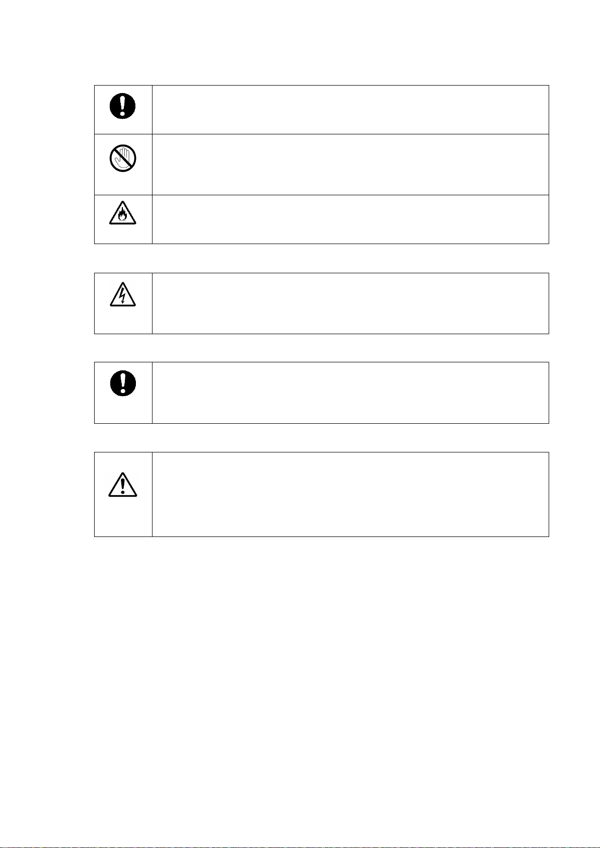
[Circuitry Access]
Do not remove covers, panels, casing, or access circuitry with power applied to the
unit! Turn power off and disconnect power cord prior to removal. Internal servicing /
adjustment of unit should only be performed by qualified personnel.
Do not touch any parts / circuitry with a high heat factor.
Capacitors can retain enough electric charge to cause mild to serious shock, even
after power is disconnected. Capacitors associated with the power supply are
especially hazardous. Avoid contact with any capacitors.
Unit should not be operated or stored with cover, panels, and / or casing removed.
Operating unit with circuitry exposed could result in electric shock / fire hazards or
unit malfunction.
If abnormal smells or noises are noticed coming from the unit, turn power off
immediately and disconnect power cord to avoid potentially hazardous conditions. If
problems similar to above occur, contact authorized service representative before
attempting to again operate unit.
To rack mount or ground the unit, or to install rubber feet, do not use screws or
materials other than those supplied. Otherwise, it may cause damage to the internal
circuits or components of the unit. If you remove the rubber feet attached on the unit,
do not reinsert the screws securing the rubber feet.
The consumables used in unit must be replaced periodically. For further details on
which parts are consumables and when they should be replaced, refer to the
specifications at the end of the Operation Manual. Since the service life of the
consumables varies greatly depending on the environment in which they are used,
they should be replaced at an early date. For details on replacing the consumables,
contact your dealer.
Caution
Caution
Caution
Hazard
Stop
[Potential Hazards]
[Rack Mount Brackets, Ground Terminal, and Rubber Feet]
[Consumables]
4
Page 5
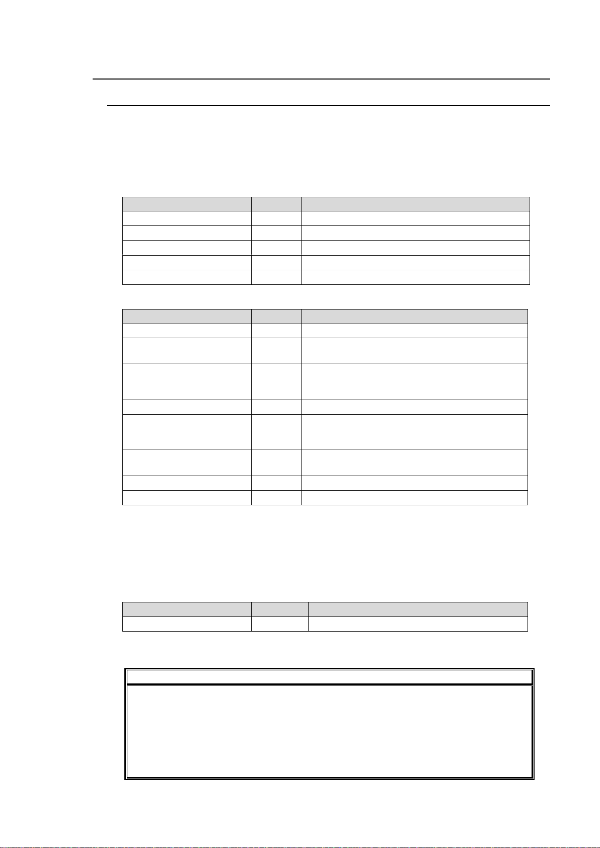
Upon Receipt
ITEM
QTY
REMARKS
FA-9520
1
AC Cord
1 set
(Incl. ladder strap/retaining clip assembly)
Rack Mount Brackets
1 set
EIA standard type (Including 4 screws.)
CD-ROM
1
FA-9520/FA-9500 User Manuals (PDF)
Quick Setup Guide
1
ITEM
QTY
REMARKS
FA-95RU
1
Remote Control Unit
FA-95PS
1 set
Redundant power supply unit (with AC cord and
AC cord retaining clip)
FA-95DACBL *
1
Digital audio expansion cable (to expand digital
audio I/O up to 8 inputs and 8 outputs.)
Normally installed in slot B.
FA-95D-D *
1-2
Dolby E/Digital decoder
FA-95DE-E*
1-2
Dolby E encoder
FA-95D-D option required for FA-95DE-E
installation.
FA-95AIO *
1-2
Analog component I/O expansion card
(with dedicated connection cable: PC-3307-1)
FA-95ALA *
1-2
Automatic Loudness Adjustment card
FA-10DCCRU
1
Remote Control Unit for color correction.
ITEM
QTY
REMARKS
FA-95CO *
1
Changeover
IMPORTANT
The FA-9520 has 2 operational modes; FA-9500 mode, in which the unit
operates/functions almost the same as the former FA-9500, and FA-9520 mode with 2
independently operational frame synchronizers. After purchase, select an FA-9520
operational mode for the first time. Refer to section 7-1 “MU OPERATION” for details
on the mode selection procedure. This operation manual describes the operation in
FA-9520 mode. When operating in FA-9500 mode, refer to the separate FA-9520
operation manual (FA-9500 mode).
Unpacking
FA-9520 units and their accessories are fully inspected and adjusted prior to shipment.
Operation can be performed immediately upon completing all required connections and
operational settings.
Check your received items against the packing lists below.
FA-9520
Option
* In FA-9520 mode, FA-95D-D, FA-95DE-E, FA-95AIO and FA-95ALA option cards can be
installed into either or both option slots A and B. In FA-9500 mode, only the card in slot A is
effective, if 2 of the same option cards are installed into both slots. Also, only the card in slot
A is effective, when FA-95D-D and FA-95DE-E are installed into both slots.
The FA-95DACBL option can be installed into either option slot A or B, however, not into both
slots.
Software Option
* FA-95CO is effective only in FA-9500 mode.
Software installation can be verified in the “SOFT OPTION1” and “SOFT OPTION2” menus.
5
Page 6
Check
2)
4)
3)
5)
6)
1)
2)
Check to ensure no damage has occurred during shipment. If damage has occurred, or items
are missing, inform your supplier immediately.
Trademark
Microsoft and Windows are either registered trademarks or trademarks of Microsoft
Corporation in the United States and/or other countries.
Pentium and Intel Core are trademarks of Intel Corporation in the U.S. and/or other countries.
Firefox is a registered trademark of the Mozilla Foundation.
Dolby is a trademark of Dolby Laboratories.
All other trademarks are trademarks or registered trademarks of their respective owners.
Rack Mounting
FA-9520/RPS can be mounted to EIA standard rack units. When rack mounting a unit, remove
the rubber feet and use the accessory rack mount brackets (rack ears).
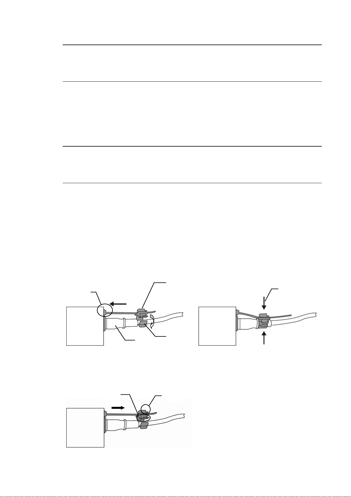
Installing the AC Cord Retaining Clip
Secure the AC cord with the supplied ladder strap/retaining clip assembly to prevent accidental
removal from the FA-9520.
Installing the clip
1) Wrap the retaining clip around the AC cord. (with the anchor of the ladder strap toward the
unit.)
2) Insert the anchor into the hole next to the AC IN socket.
3) Lightly fasten the clip around the AC cord.
4) Plug in the power cord.
5) Slide the clip on the ladder strap toward the plug.
6) Fasten the clip tightly.
7) Gently pull on the AC cord to ensure it is secured.
Unplugging the AC cord
1) Push the tab on the retaining up to unfasten the clip.
2) Push the tab on the ladder strap up and slide the clip back.
3) Unplug the AC cord.
6
Page 7

Table of Contents
1. Prior to Starting ......................................................................................................................... 15
1-1. Welcome ............................................................................................................................ 15
1-2. Features ............................................................................................................................ 15
1-3. FA-95LG GUI Download ................................................................................................... 15
2. Panel Descriptions .................................................................................................................... 16
2-1. Front Panel ........................................................................................................................ 16
2-2. Rear Panel ......................................................................................................................... 18
2-3. Internal Settings ................................................................................................................ 21
2-3-1. Dipswitch Settings ...................................................................................................... 21
3. Connections .............................................................................................................................. 22
3-1. For 2-Channel Frame Synchronizer Use .......................................................................... 22
3-2. For HD/SD-SDI Simul Output ............................................................................................ 23
3-3. To Embed AES Input Signals on SDI Signals .................................................................. 24
3-4. To Embed Analog Audio Signals on SDI Signals ............................................................. 25
3-5. Connecting a Computer .................................................................................................... 26
3-6. Connecting to the REMOTE (GPI) Connector .................................................................. 27
4. Front Panel Operation .............................................................................................................. 28
4-1. Powering ON ..................................................................................................................... 28
4-2. Basic Operation ................................................................................................................. 28
4-2-1. Accessing Menus ....................................................................................................... 29
4-2-2. Menu Buttons ............................................................................................................. 30
4-2-3. Arrow Buttons ............................................................................................................. 32
4-2-4. Consecutive Viewing of Settings ................................................................................ 32
4-2-5. Page Jump Feature .................................................................................................... 33
4-2-6. Changing Setting Values............................................................................................ 34
4-2-7. Resetting to Default .................................................................................................... 35
4-2-8. Switching Between 2-Channel Frame Synchronizers ............................................... 35
5. VIDEO Menus ........................................................................................................................... 37
5-1. VIDEO PROC AMP (PROCESS) ...................................................................................... 37
5-2. COLOR CORRECTOR (C.C.) ........................................................................................... 37
5-2-1. WHITE LEVEL............................................................................................................ 37
5-2-2. BLACK LEVEL ........................................................................................................... 38
5-2-3. GAMMA LEVEL.......................................................................................................... 38
5-2-4. COLOR CORRECT (C.C.) ......................................................................................... 39
5-2-5. Color Corrector and AVO Modes ............................................................................... 40
5-3. CONV (UP/DOWN/CROSS CONVERTER) ..................................................................... 40
5-3-1. CONV MODE ............................................................................................................. 41
5-3-2. CONV Conversion Table............................................................................................ 42
5-3-3. CONV SIZE/POS ....................................................................................................... 42
5-3-4. CONV CROPPING ..................................................................................................... 43
5-3-5. CONV IMPROVE ....................................................................................................... 44
7
Page 8

5-3-6. CONV SIDE RGB ....................................................................................................... 45
5-4. Auto Video Optimizer (AVO) ............................................................................................. 46
5-4-1. AVO SETTING ........................................................................................................... 46
5-4-2. AVO SETUP ............................................................................................................... 47
5-4-2-1. About Scene Cut Detection and Frame Delay Settings ..................................... 48
5-4-3. USER1 - 5 LEVEL SET .............................................................................................. 49
5-4-4. USER1, 2 AREA SET ................................................................................................ 52
5-4-4-1. Manual Level Adjustment.................................................................................... 53
5-5. CLIP (VIDEO CLIP) ........................................................................................................... 54
5-5-1. YPbPr/RGB CLIP ....................................................................................................... 54
5-5-2. COMPOSITE CLIP ..................................................................................................... 55
5-5-3. VIDEO CLIP Setting Ranges ..................................................................................... 55
5-6. VIDEO INPUT SELECT (IN SEL) ..................................................................................... 57
5-6-1. FS INPUT SELECT .................................................................................................... 57
5-6-2. VIDEO INPUT SET .................................................................................................... 58
5-6-3. ANC DETECT LINE ................................................................................................... 59
5-6-4. ANC DETECT SEL .................................................................................................... 59
5-6-5. AIO A IN MODE ......................................................................................................... 60
5-6-6. AIO B IN MODE ......................................................................................................... 60
5-7. VIDEO OUT SELECT (OUT SEL)..................................................................................... 61
5-7-1. OUTPUT ASSIGN ...................................................................................................... 61
5-7-2. AIO A ASSIGN ........................................................................................................... 62
5-7-3. AIO B ASSIGN ........................................................................................................... 63
5-7-4. ANC DATA EMBED ................................................................................................... 64
5-7-5. ANC EMBED LINE ..................................................................................................... 65
5-8. VIDEO OPTION (VIDEO OP) ........................................................................................... 67
5-8-1. Logo Generator .......................................................................................................... 67
5-8-1-1. LOGO SELECT ................................................................................................... 67
5-8-1-2. KEYER SET ........................................................................................................ 68
5-8-1-3. Logo Position Setting Range .............................................................................. 68
5-9. VIDEO SYSTEM (VIDEO SYS) ........................................................................................ 69
5-9-1. FS MODE SET ........................................................................................................... 69
5-9-2. HD PHASE SET ......................................................................................................... 70
5-9-3. SD PHASE SET ......................................................................................................... 71
5-9-4. VIDEO POSITION ...................................................................................................... 72
5-9-5. FREEZE SET ............................................................................................................. 73
5-9-6. ANC SET .................................................................................................................... 74
5-9-7. ANC LOSS SET ......................................................................................................... 75
5-9-8. WSS AFD ERROR ..................................................................................................... 76
5-9-9. AUDIO GROUP .......................................................................................................... 76
5-9-10. TEST SIGNAL .......................................................................................................... 77
5-9-11. BY-PASS SETTING ................................................................................................. 77
5-9-12. AIO BY-PASS SET .................................................................................................. 78
5-9-13. SD LINE MASK ........................................................................................................ 79
5-9-14. COMPOSITE SET1 .................................................................................................. 80
8
Page 9

5-9-15. COMPOSITE SET2 .................................................................................................. 80
5-10. Various Signal Status Display (STATUS) ....................................................................... 81
5-10-1. UNIT ALARM............................................................................................................ 81
5-10-2. VIDEO IN STATUS .................................................................................................. 82
5-10-3. VIDEO OPTION INPUT ........................................................................................... 83
5-10-4. VIDEO OUT STATUS .............................................................................................. 84
5-10-5. VIDEO OPTION OUTPUT ....................................................................................... 84
5-10-6. AUDIO IN DETECT1 ................................................................................................ 85
5-10-7. AUDIO IN DETECT2 ................................................................................................ 85
5-10-8. AUDIO OUTPUT1 .................................................................................................... 86
5-10-9. AUDIO OUTPUT3 .................................................................................................... 86
5-10-10. EMB 1 IN AUDIO ................................................................................................... 87
5-10-11. EMB 2 IN AUDIO ................................................................................................... 88
5-10-12. AES IN AUDIO ....................................................................................................... 89
5-10-13. ANALOG IN AUDIO ............................................................................................... 89
5-10-14. SDI 1/2 OUT AUDIO .............................................................................................. 90
5-10-15. SDI 3/4 OUT AUDIO .............................................................................................. 91
5-10-16. AES OUT AUDIO ................................................................................................... 91
5-10-17. ANALOG OUT AUDIO ........................................................................................... 92
5-10-18. Dolby OPA AUX ..................................................................................................... 92
5-10-19. Dolby OPB AUX ..................................................................................................... 93
5-10-20. AFD IN STATUS .................................................................................................... 94
5-10-21. ANC1 IN STATUS .................................................................................................. 94
5-10-22. ANC1 IN STATUS 1-2............................................................................................ 95
5-10-23. ANC OUT ............................................................................................................... 95
5-10-24. S2016 OUT ............................................................................................................ 95
5-10-25. VI OUT ................................................................................................................... 96
5-10-26. WSS OUT ............................................................................................................... 96
5-10-27. ANC OUT1 ............................................................................................................. 97
6. AUDIO Settings ........................................................................................................................ 98
6-1. SDI AUDIO Settings (SDI AUDIO) .................................................................................... 98
6-1-1. EMB1 IN GAIN ........................................................................................................... 98
6-1-2. EMB1 OUT MONO ..................................................................................................... 98
6-1-3. EMB1 IN SET ............................................................................................................. 99
6-1-4. EMB1 OUT CLOCK ................................................................................................. 100
6-1-5. EMB2 IN GAIN ......................................................................................................... 101
6-1-6. EMB2 OUT MONO ................................................................................................... 101
6-1-7. EMB2 IN SET ........................................................................................................... 102
6-1-8. EMB2 AUDIO CLOCK .............................................................................................. 103
6-2. AES AUDIO Settings (AES AUDIO) ............................................................................... 104
6-2-1. AES IN GAIN ............................................................................................................ 104
6-2-2. AES HYSTERESIS .................................................................................................. 104
6-2-3. AES OUT MONO ..................................................................................................... 105
6-2-4. AES I/O SETUP ....................................................................................................... 105
9
Page 10

6-3. ANALOG AUDIO Settings (ANALOG) ............................................................................ 106
6-3-1. ANALOG IN LEVEL ................................................................................................. 106
6-3-2. ANALOG IN GAIN .................................................................................................... 106
6-3-3. ANALOG OUT LEVEL ............................................................................................. 106
6-3-4. ANALOG OUT MONO ............................................................................................. 107
6-3-5. ANALOG IN SYSTEM .............................................................................................. 107
6-4. OUTPUT GAIN CONTROL ............................................................................................. 108
6-4-1. MASTER OUT GAIN ................................................................................................ 108
6-4-2. EMB1 OUT GAIN ..................................................................................................... 108
6-4-3. EMB2 OUT GAIN ..................................................................................................... 109
6-4-4. AES OUT GAIN ........................................................................................................ 109
6-4-5. ANALOG OUT GAIN ................................................................................................ 110
6-5. AUDIO MAPPING (MAPPING) ....................................................................................... 111
6-5-1. EMB1 OUT REMAP ................................................................................................. 111
6-5-2. EMB2 OUT REMAP ................................................................................................. 112
6-5-3. AES OUT REMAP .................................................................................................... 113
6-5-4. ANALOG OUT REMAP ............................................................................................ 114
6-6. AUDIO DELAY Settings .................................................................................................. 115
6-6-1. EMB1 IN DELAY ...................................................................................................... 115
6-6-2. EMB2 IN DELAY ...................................................................................................... 115
6-6-3. AES IN DELAY ......................................................................................................... 115
6-6-4. ANALOG IN DELAY ................................................................................................. 116
6-7. DOWN MIX1 SET ............................................................................................................ 117
6-7-1. DOWN MIX1 ASSIGN .............................................................................................. 118
6-8. DOWN MIX2 SET ............................................................................................................ 119
6-8-1. DOWN MIX2 ASSIGN .............................................................................................. 120
6-9. AUDIO MODE SET (MODE) ........................................................................................... 121
6-9-1. EMB1 SRC MODE ................................................................................................... 121
6-9-2. EMB2 SRC MODE ................................................................................................... 121
6-9-3. AES SRC MODE ...................................................................................................... 122
6-9-4. EMB1 POLARITY ..................................................................................................... 122
6-9-5. EMB2 POLARITY ..................................................................................................... 122
6-9-6. AES POLARITY ....................................................................................................... 123
6-9-7. ANALOG POLARITY ............................................................................................... 123
6-9-8. Dolby A POLARITY .................................................................................................. 124
6-9-9. Dolby B POLARITY .................................................................................................. 124
6-10. AUDIO OPTION (AUDIO OP) ....................................................................................... 125
6-10-1. FA-95D-D / FA-95DE-E.......................................................................................... 125
6-10-1-1. Dolby AUX OUT .............................................................................................. 125
6-10-1-2. Dolby DEC IN .................................................................................................. 126
6-10-1-3. Dolby DECODER REFERENCE .................................................................... 127
6-10-1-4. Dolby DOWNMIX ............................................................................................ 127
6-10-1-5. Dolby DECODER GAIN .................................................................................. 128
6-10-1-6. Dolby ENCODER INPUT ................................................................................ 129
6-10-1-7. Dolby ENCODER SETTING ........................................................................... 130
10
Page 11

6-10-1-8. METADATA INPUT ......................................................................................... 131
6-10-2. Automatic Loudness Adjustment (FA-95ALA) ....................................................... 132
6-10-2-1. LOUDNESS MEASUREMENT ....................................................................... 132
6-10-2-2. LOUDNESS CONTROL ENABLE .................................................................. 133
6-10-2-3. LOUDNESS CONTROL SETTINGS .............................................................. 134
6-10-2-4. LOUDNESS CHANNEL ASSIGNMENT ......................................................... 135
6-10-2-5. LOUDNESS STANDARD ............................................................................... 136
6-11. AUDIO SYSTEM Settings (AUDIO SYS) ...................................................................... 137
6-11-1. FADE IN / OUT....................................................................................................... 137
6-11-2. DIGITAL AUDIO ..................................................................................................... 138
6-11-3. AUDIO ERR SENSE .............................................................................................. 138
6-11-4. DIGITAL SILENCE ................................................................................................. 140
7. Other Settings & Information (OTHER) .................................................................................. 141
7-1. FS1/FS2 COPY ............................................................................................................... 141
7-2. MU OPERATION ............................................................................................................. 142
7-2-1. Important Note on Changing the Operation Mode ................................................... 142
7-2-2. FA-9520 Operation Mode Change Procedure ......................................................... 142
7-3. CONTROL SETTING ...................................................................................................... 143
7-4. FRONT OPERATION ...................................................................................................... 143
7-5. FRONT PANEL SET ....................................................................................................... 143
7-6. GPI SETTING .................................................................................................................. 144
7-7. NETWORK INFO ............................................................................................................ 147
7-8. UNIT Ver. ......................................................................................................................... 147
7-9. OPTION A Ver. ................................................................................................................ 148
7-10. OPTION B Ver. .............................................................................................................. 148
7-11. OTHER OPTION ........................................................................................................... 149
7-12. SOFT OPTION1 ............................................................................................................ 149
7-13. SOFT OPTION2 ............................................................................................................ 149
8. Event Memory......................................................................................................................... 150
8-1. EVENT LOAD .................................................................................................................. 150
8-2. EVENT SAVE .................................................................................................................. 151
8-3. EVENT SETUP ............................................................................................................... 151
8-4. Parameters Not Stored in Event Memory ....................................................................... 151
8-5. Note on Event Memory Operation .................................................................................. 151
9. Control via WEB Browser ....................................................................................................... 152
9-1. Connecting via a WEB Browser ...................................................................................... 152
9-2. VIDEO Settings ............................................................................................................... 153
9-2-1. FS Input Select ......................................................................................................... 154
9-2-2. Auto Video Optimizer (AVO) .................................................................................... 155
9-2-2-1. About Scene Cut Detection and Frame Delay Settings ................................... 157
9-2-2-2. User 1 - 5 LEVEL SET ...................................................................................... 158
9-2-2-3. User Area 1, 2 ................................................................................................... 160
9-2-3. Frame Delay ............................................................................................................. 161
9-2-4. Proc Amp .................................................................................................................. 162
11
Page 12

9-2-5. BY-PASS Setting ..................................................................................................... 163
9-2-6. Converter .................................................................................................................. 164
9-2-7. Color Corrector ......................................................................................................... 168
9-2-8. Video Test Signal ..................................................................................................... 171
9-2-9. YPbPr/RGB Clip ....................................................................................................... 172
9-2-10. Output Assign ......................................................................................................... 173
9-2-11. Composite Clip ....................................................................................................... 175
9-3. AUDIO Settings ............................................................................................................... 176
9-3-1. SDI Input .................................................................................................................. 177
9-3-2. AES Audio Input Settings ......................................................................................... 179
9-3-3. Analog Audio Input ................................................................................................... 181
9-3-4. Audio Delay (SDI / AES / Analog) ............................................................................ 182
9-3-5. SRC Mode (SDI / AES) ............................................................................................ 183
9-3-6. Audio Output Polarity (SDI / AES / Analog) ............................................................. 184
9-3-7. Audio Mapping ......................................................................................................... 185
9-3-8. Audio Master Gain Settings ..................................................................................... 187
9-3-9. Down Mix Setting ..................................................................................................... 188
9-3-10. SDI Audio Output Settings ..................................................................................... 190
9-3-11. AES Audio Output Settings .................................................................................... 191
9-3-12. Analog Audio Output Settings ................................................................................ 191
9-3-13. Dolby E/Digital Decoder ......................................................................................... 192
9-3-14. Dolby AUX Output Select ....................................................................................... 194
9-3-15. Dolby E Encoder .................................................................................................... 195
9-3-16. Automatic Loudness Adjustment (FA-95ALA) ....................................................... 197
9-4. SYSTEM Settings ............................................................................................................ 200
9-4-1. FS1/FS2 Video System ............................................................................................ 200
9-4-2. Audio System ........................................................................................................... 205
9-4-3. ANC Settings ............................................................................................................ 208
9-4-4. Composite Settings .................................................................................................. 212
9-5. GPI................................................................................................................................... 213
9-6. Utility Settings .................................................................................................................. 215
9-6-1. Event Control ............................................................................................................ 216
9-6-2. Backup Parameter ................................................................................................... 217
9-6-3. Downloading a MIB File ........................................................................................... 218
9-6-4. Event Data Backup .................................................................................................. 219
9-7. Status Display.................................................................................................................. 220
9-7-1. Unit/Video Status ..................................................................................................... 220
9-7-2. Audio Status ............................................................................................................. 223
9-7-3. Unit Information ........................................................................................................ 225
9-7-4. ANC Status ............................................................................................................... 226
9-8. Network Settings ............................................................................................................. 229
9-8-1. Network Information ................................................................................................. 229
9-8-2. NETWORK SETTING .............................................................................................. 229
9-8-3. SNMP SETTING ...................................................................................................... 230
9-8-4. TRAP SETTING ....................................................................................................... 232
12
Page 13

9-8-5. USER SETTING ....................................................................................................... 233
9-8-6. Restart ...................................................................................................................... 233
10. Downmix Block Diagram ...................................................................................................... 234
11. ANALOG/DIGITAL Audio Input/Output Level ...................................................................... 235
11-1. Analog Output Level Relative to the Digital Input Level ............................................... 235
11-2. Digital Output Level Relative to the Analog Input Level ............................................... 236
12. Analog Audio Connection ..................................................................................................... 237
13. Dolby E Decoder/Encoder Channel Assignment Table ....................................................... 238
14. REMOTE .............................................................................................................................. 239
14-1. REMOTE Connector ..................................................................................................... 239
14-2. GPI Input Circuit ............................................................................................................ 239
14-3. GPI Input Control ........................................................................................................... 240
14-4. GPI Output Circuit ......................................................................................................... 241
15. How to Install the FA-95DACBL ........................................................................................... 242
15-1. Procedure ...................................................................................................................... 242
15-2. Installation Confirmation ................................................................................................ 243
16. FA-95AIO Option .................................................................................................................. 244
16-1. FA-95AIO Pin Assignments .......................................................................................... 244
16-2. FA-95AIO Switch Settings ............................................................................................. 245
17. System Requirements .......................................................................................................... 245
18. About SNMP (Simple Network Management Protocol) ....................................................... 246
19. FA-9520 Ancillary Data Packet Name List ........................................................................... 259
20. About AFD (Active Format Description) ............................................................................... 261
20-1. AFD Codes .................................................................................................................... 262
20-2. Aspect Ratio Conversion with AFD ............................................................................... 264
20-3. AFD Supported Video Formats ..................................................................................... 268
20-4. AFD Based Auto Aspect Conversion Settings .............................................................. 268
20-5. How to Insert AFD Data to Output Video Signals ......................................................... 269
20-6. AFD Code Abbreviations ............................................................................................... 270
21. About Closed Captioning ...................................................................................................... 272
21-1. Closed Captioning Setting Procedure ........................................................................... 272
22. Verification After Option Card Removal/Replacement ......................................................... 273
22-1. Alert ............................................................................................................................... 273
22-2. Verification After Dolby Option Removal/Replacement ................................................ 273
22-3. Verification After FA-95AIO Removal/Replacement ..................................................... 273
22-4. Verification After FA-95ALA Removal/Replacement .................................................... 274
23. Expansion Slots A / B Alert .................................................................................................. 274
24. Specifications and Dimensions ............................................................................................ 275
24-1. Unit Specifications ......................................................................................................... 275
13
Page 14

24-2. External Dimensions ..................................................................................................... 278
14
Page 15

1. Prior to Starting
1-1. Welcome
Congratulations! By purchasing FA-9520 Frame Synchronizer you have entered the world of
FOR-A and its many innovative products. Thank you for your patronage and we hope you will
turn to FOR-A products again and again to satisfy your video and audio needs.
FOR-A provides a wide range of products, from basic support units to complex system
controllers, which have been increasingly joined by products for computer video based systems.
Whatever your needs, talk to your FOR-A representative. We will do our best to be of continuing
service to you.
1-2. Features
The FA-9520 is a multipurpose signal processor loaded with all the functions you need for video
production.
3G-SDI, HD/SD-SDI, and analog composite I/O is supported in addition to its functionality as a
frame synchronizer. The unit provides dual up/down/cross/aspect converters, color corrector,
and automatic video optimizer (AVO) as standard features, allowing for the conversion of many
types of video and audio signals. Numerous additional optional features include analog
component I/O, logo generator, Dolby E encoder and Dolby E decoder. By combining these
varied options, a single unit can provide optimal functionality for all your video production scene
requirements, including transmission, live production, news reporting, video production, editing
and distribution. As long as you have the FA -9520, you will never need another piece of
peripheral video equipment!
Standard Features
3G-SDI/HD-SDI/SD-SDI/Analog Composite I/O
Digital/Analog Audio I/O
Main Converter (Up/Down/Cross/Aspect conversion)
Second Converter (Up/Down/Cross/Aspect conversion)
Color Corrector
Auto Video Optimizer (AVO)
Powerful Frame Synchronizer Performance
Logo Generator
Other Features
Video delay
2D/3D comb filter for Y/C separator (composite)
Web browser-based monitoring and control possible
SNMP monitoring and partial control function
Additional Features
Redundant power supply unit
Digital audio expansion cable
Changeover function (in FA-9500 mode only)
Dolby E/Digital decoder and Dolby E encoder
Analog component I/O
Automatic Loudness Adjustment Function
Remote control unit via Ethernet
1-3. FA-95LG GUI Download
The FA-9520 Logo generator function is designed to be used with logo management software,
FA-95LG GUI, enabling logo data import to FA-9520 via Ethernet. The FA-95LG GUI can be
downloaded from FOR-A’s website: http://www.for-a.com/products/fa9500/fa95lg_gui.zip. The
operation manual for the FA-95LG GUI will download automatically along with the software.
15
Page 16
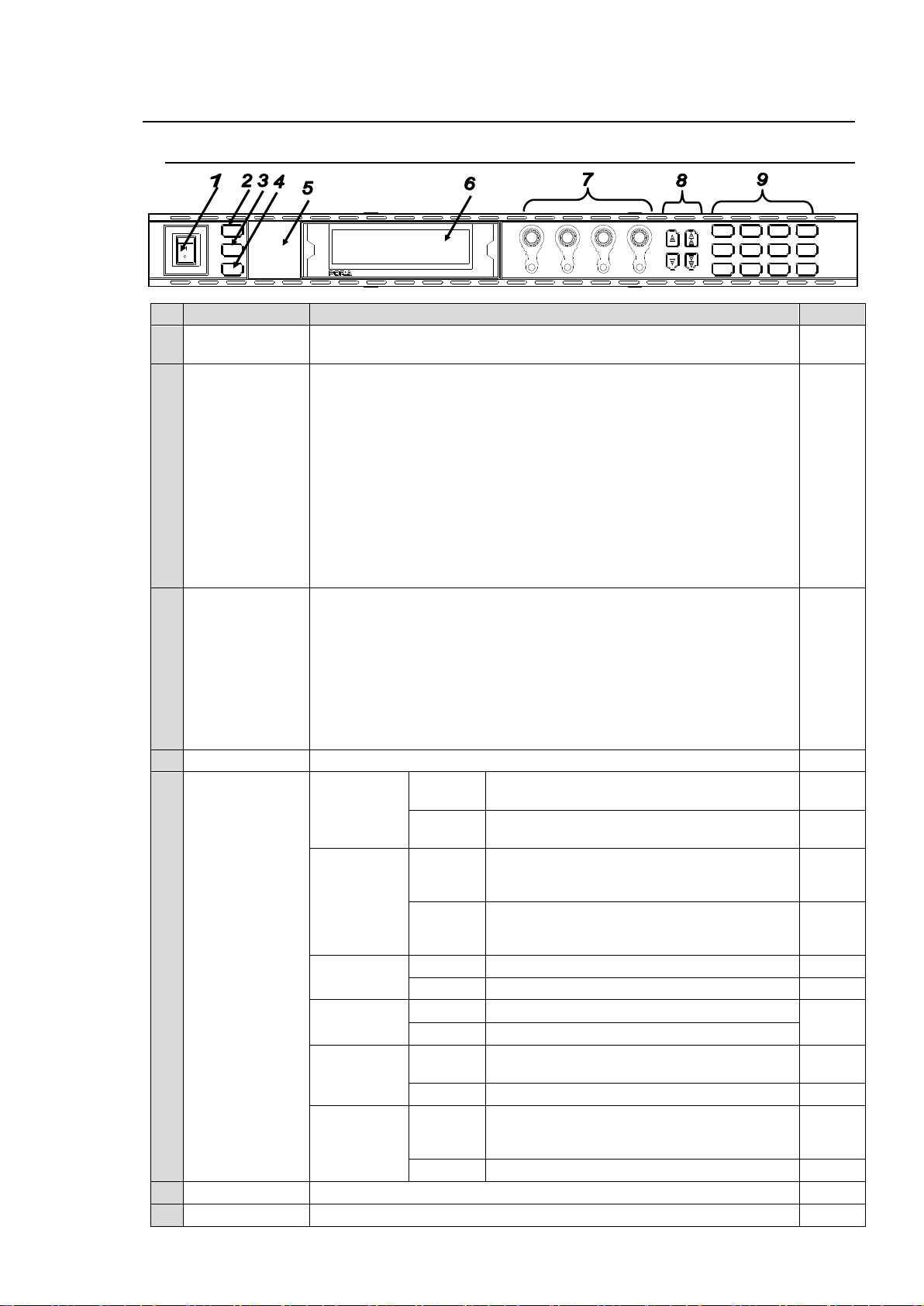
2. Panel Descriptions
No
Name
Description
Ref.
1
POWER switch
Used to turn the unit ON / OFF. Pressing the "|" side turns on the
power.
4-1
2
LOCK button
(FA-9500 mode)
FS1/LOCK
(FA-9520 mode)
In FA-9500 mode:
Lit when pressed, and the buttons and controls on the front panel
except this LOCK button are disabled.
To enable the disabled buttons and controls, press and hold this button
down for several seconds.
In FA-9520 mode:
Used to select FS1 or FS2. There are linked menus that can be
changed simultaneously by pressing the FS1/LOCK and FS2/LOCK
buttons simultaneously. See 4-2-8 “2-channel frame synchronizer
switching” for details.
Disables operation only for FS1 when pressed and held down.
Press and hold this button down again to unlock operation.
* Both FS1 and FS2 LOCKs can be set simultaneously to disable all
other buttons except themselves.
3
FS2/LOCK
(FA-9520 mode)
In FA-9500 mode: Ineffective
In FA-9520 mode:
Used to select FS1 or FS2. There are linked menus that can be
changed simultaneously by pressing FS1/LOCK and FS2/LOCK
buttons simultaneously. See 4-2-8 “Switching Between 2-Channel
Frame Synchronizers” for details.
Disables operation only for FS2 when pressed and held down.
Press and hold this button down again to unlock operation.
* Both FS1 and FS2 LOCKs can be set simultaneously to disable all
other buttons except themselves.
4-2-8
4
EVENT button
Used to save and load events.
8
5
Status indicator
VIDEO IN
Lit green
Input signal is present in FS1 or FS2.
5-6-1
5-10-2
Unlit
No input signal is present in FS1 or FS2.
5-6-1
5-10-2
AUDIO IN
Lit green
One or more assigned audio output signals
(FS1, FS2 embedded, AES and/or analog
audio) are present.
6-5
Unlit
No assigned audio signal (FS1, FS2
embedded, AES and/or analog audio) is
present.
6-5
GENLOCK
Lit green
Genlock signal input is present.
5-10-2
Unlit
No genlock signal input is present.
5-10-2
REMOTE
Lit green
CONTROL SETTING is set to REMOTE.
7-3
Unlit
CONTROL SETTING is set to LOCAL.
DC POWER
*1
Lit red
A power failure has occurred. Turn the power
of the unit OFF, and contact your supplier.
5-10-1
Unlit
Power supply is normal.
5-10-1
FAN ALARM
Lit red
One or more fans have failed. Turn the power
of the unit OFF, and replace the failed fans if
needed.
5-10-1
Unlit
All fans are operating normally.
5-10-1
6
Menu display
Used to display menus and make operational settings
4-2
7
Controls (F1-F4)
Used to change operational settings. Turn and select values.
4-2
MASTER
CONV2
OUT SEL
MODE
VIDEO
AUDIO
ANALOG
CONV1
IN SEL
DOWNMIX
STATUS
OTHER
C C
AES AUDIO
CLIP
DELAY
AUDIO SYS
VIDEO SYS
AUDIO OP
VIDEO OP
MAPPING
A V O
PROCESS
SDI AUDIO
F4
UNITYUNITYUNITYUNITY
F3
F2
F1
F A - 9 5 0 0
DISPLAY AREA
HD / S D FR A ME S YS N CH RO NI ZE R
VIDEO IN
AUDIO IN
GENLOCK
REMOTE
FAN ALARM
DC POWER
BY-PASS
LOCK
EVENT
ON
OFF
POWER
F1
F2
F3
F4
2-1. Front Panel
16
Page 17

UNITY buttons
The Unity buttons return the settings to the default values.
8
Arrow buttons
Single-arrow buttons
Used to move between parameters.
(Indicators light up to indicate the accessible
direction.)
4-2
Double-arrow
buttons
Used to move between menus (same as the
menu buttons). (Indicators light up to indicate the
accessible direction.)
4-2
9
Menu buttons
Used to select menus.
4-2
*1 The DC POWER indicator functions when the optional FA-95PS is installed.
17
Page 18
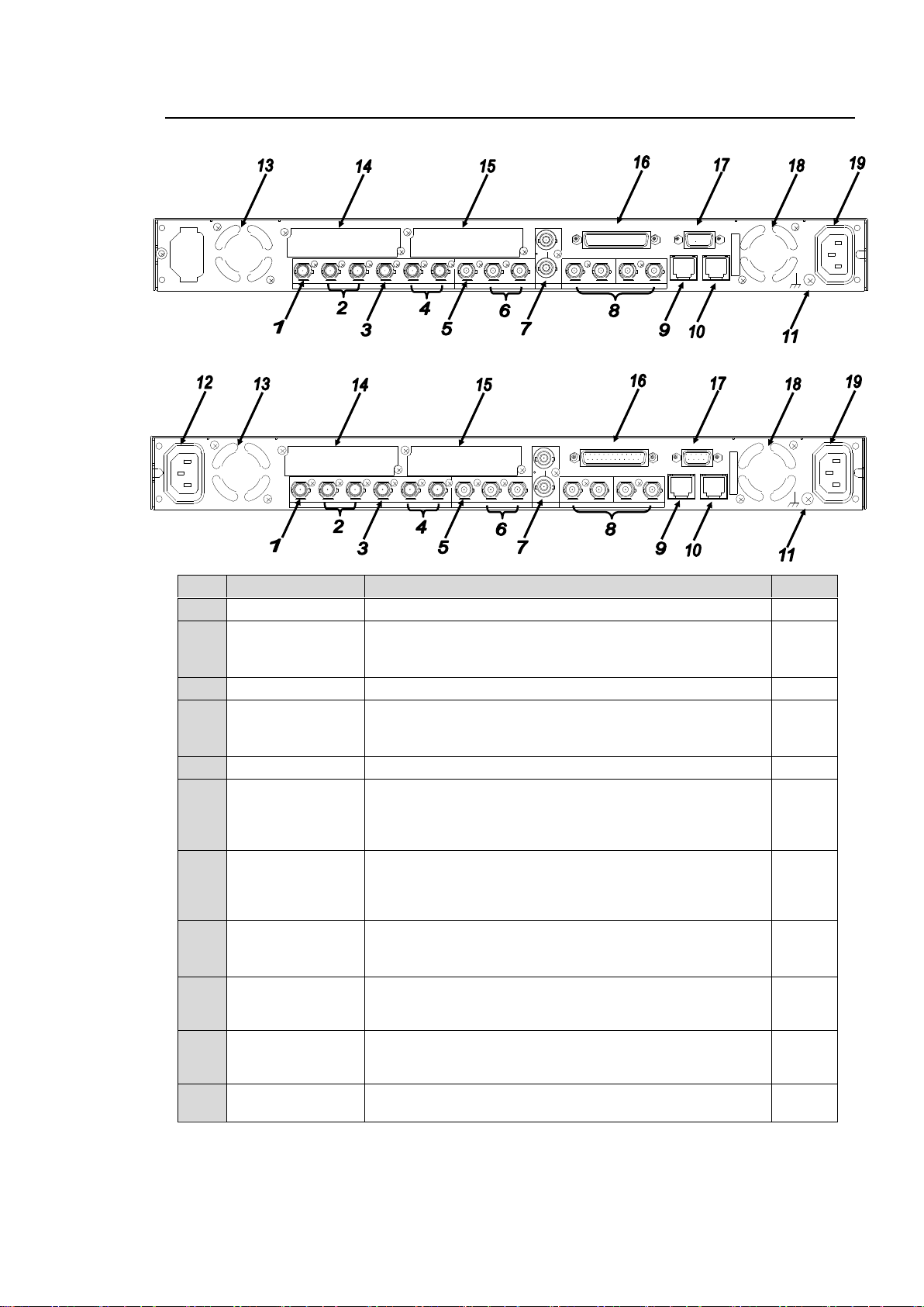
2-2. Rear Panel
No
Name
Description
Ref.
1
SDI IN 1
Used for HD/SD-SDI video input 1.
5-6
2
SDI OUT 1-2
Used for HD/SD-SDI video output 1.
The input signal in SDI IN 1 is output from SDI OUT1
when BY-PASS is enabled or the unit is turned off.
5-10-4
3
SDI IN 2
Used for HD/SD-SDI video input 2.
5-6
4
SDI OUT 3-4
Used for HD/SD-SDI video output 2.
The input signal in SDI IN 2 is output from SDI OUT3
when BY-PASS is enabled or the unit is turned off.
5-10-4
5
COMPOSITE IN
Used for analog composite video input.
5-6
6
COMPOSITE
OUT 1-2
Used for analog composite video output.
The input signal in COMPOSITE IN is output from
COMPOSITE OUT1 when BY-PASS is enabled or the
unit is turned off.
5-10-4
7
GENLOCK IN
Used for reference signal input (black burst or tri-level
sync) to synchronize the system. The bottom connector is
for a loop through. It must be terminated at 75 ohm when
not in use.
5-10-2
8
DIGITAL AUDIO
IO
1/2 - 7/8
Used for digital audio inputs and outputs. Select whether
to use for input or output as in section 6-2-4 “AES I/O
SETUP”.
6-2-4
9
LAN1
A 1000/100BASE-TX/10BASE-T Ethernet LAN port.
Used to connect an external remote control unit or to
transfer data to an external device. RJ-45
3-5
10
LAN2
A 1000/100BASE-TX/10BASE-T Ethernet LAN port.
Used to connect an external remote control unit or to
transfer data to an external device. RJ-45 (For future use)
11
Ground Terminal
Used to ground the unit to protect operators against static
electricity and electrical shock.
AC100 - 240V 50/60 Hz IN 1
FAN2
SER. NO.
LAN2LAN1
REMOTE
DIGITA L AUD IO IN / OUT
7 / 85 / 63 / 41 / 2
ANALOG A UDIO
GENLO CK INCOMPO SITE
OUT2OUT1IN
B
OUT4OUT3IN2OUT2OUT1
SDI
IN1
A
FAN1
AC100 - 240V 50/60 Hz IN2
AC100 - 240V 50/60 Hz IN 1
FAN2
SER. NO.
LAN2LAN1
REMOTE
DIGITAL AU DIO IN / O UT
7 / 85 / 63 / 41 / 2
ANALOG AUDIO
GENLOCK IN
COMPOSIT E
OUT2OUT1IN
B
OUT4OUT3IN 2OUT2OUT1
SDI
IN1
A
FAN1
AC100 - 240V 50/60 Hz IN2
FA-9520
FA-9520 with the FA-95PS option installed
18
Page 19
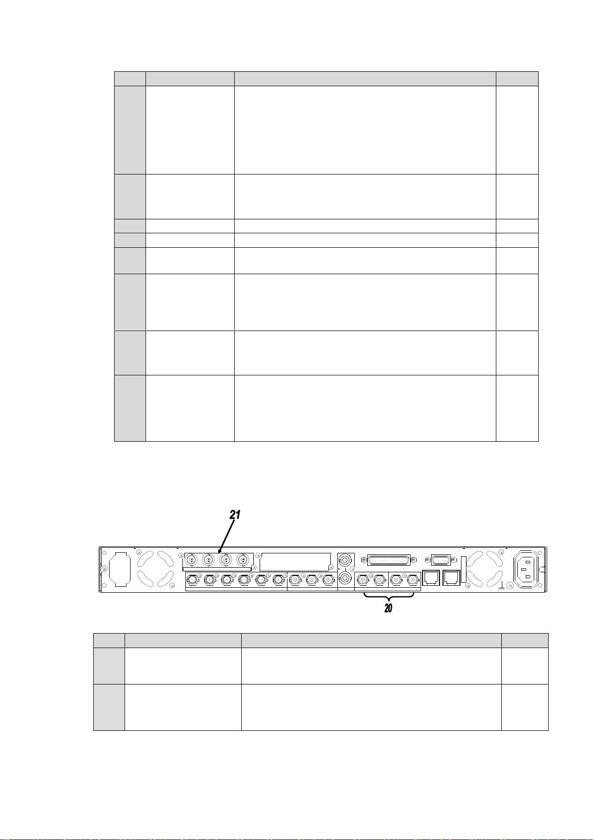
No
Name
Description
Ref.
12
AC IN 2
Used to connect the unit to an AC power source.
(AC100V-240V 50/60Hz)
Enabled only when the optional redundant power unit
FA-95PS is installed.
The operation status can be viewed from the DC POWER
2 menu as described in section 5-10-1 “UNIT ALARM”.
(The menu is displayed if the optional FA-95PS is
installed.)
13
FAN1
Used to air-cool the unit to prevent overheating. Do not
block the ventilation with other equipment or objects. The
operation status can be viewed from the FAN1 menu as
described in section 5-10-1 “UNIT ALARM”.
5-10-1
14
SLOT A
OPTION SLOT A for an optional expansion card.
15
15
SLOT B
OPTION SLOT B for an optional expansion card.
15
16
ANALOG AUDIO
Used for four-channel analog audio input and output.
See section 12 “Analog Audio Connection” for details.
12
17
REMOTE
Used for remote control.
Assign functions to each pin.
See section 7-6 “GPI SETTING” for details on assigning
functions.
See section 14 “REMOTE” for connections.
7-6
14
18
FAN2
Used to air-cool the unit to prevent overheating. Do not
block the ventilation with other equipment or objects. The
operation status can be viewed from the FAN2 menu as
described in section 5-10-1 “UNIT ALARM”.
5-10-1
19
AC IN1
Used to connect the unit to an AC power source.
(AC100V-240V 50/60Hz)
The operation status can be viewed from the DC POWER
1 menu as described in section 5-10-1 “UNIT ALARM”.
(The menu is displayed if the optional FA-95PS is
installed.)
5-10-1
No
Name
Description
Ref.
20
DIGITAL AUDIO IO
1/2 - 7/8
Digital audio input and output connectors.
Used only for inputs when the FA-95DACBL option is
installed.
6-2-4
21
DIGITAL AUDIO OUT
1/2 - 7/8
Digital audio output connectors. (FA-95DACBL option)
(The above figure of rear panel depicts an FA-95DACBL
option installed in slot A. The option can also be installed
in slot B.)
15
3/4 5/61/2 7/8
FAN2
3/4 7/8
FAN1
5/6
BA
COMPO SITE
1/2
LAN2
SDI
REMOTE
LAN1
COMPO SITE
OUT3OUT2IN 1
SDI
ANALOG A UDIO
LAN2
DIGITAL AUDIO IN/OUT
OUT4OUT1 IN2 OUT1 OUT2IN
A
C
100-240V 50/60H
z IN
2
DIGITA L AUDIO OUT
S
E
R
.
N
O
.
GENLOCK IN
AC100-240V 50/60Hz IN 1
FA-9520 with the FA-95DACBL option installed
19
Page 20
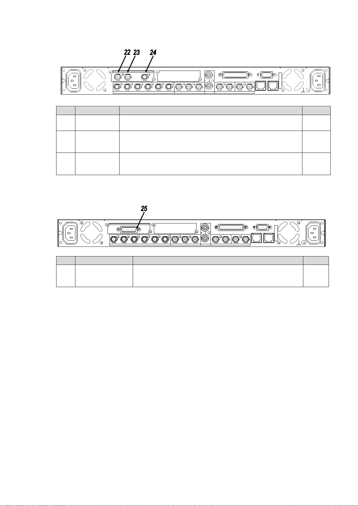
FA-9520 with the FA-95D-D/DE-E options installed
No
Name
Description
Ref.
22
Dolby E IN
(AUX IN)
Digital audio input connector on the FA-95D-D/DE-E option.
Used to input Dolby E and/or digital signals to the Dolby decoder.
6-10-12
23
Dolby E OUT
(AUX OUT)
Digital audio output connector on the FA-95D-D/DE-E option.
Used to output signals output from the Dolby decoder and/or Dolby
encoder.
6-10-11
24
REF IN
Reference signal input connector on the FA-95D-D/DE-E option.
Used to input reference signal (B.B. or tri-level sync) for the Dolby
decoder. 75 ohm terminated inside.
6-10-13
No
Name
Description
Ref.
25
ANALOG
COMPONENT I/O
Analog component input/output connector on FA-95AIO
option.
Connect the supplied I/O cable.
16
AC100 - 240V 50/60 Hz IN 1
FAN2
SER. NO.
LAN2LAN1
REMOTE
DIGITAL AUDIO IN / OUT
7 / 85 / 63 / 41 / 2
ANALOG AUDIO
GENL OCK INCOMPOSITE
OUT2O UT1IN
B
OUT4OUT3IN2OUT2OUT1
SDI
IN1
A
FAN1
AC100 - 240V 50/60 Hz IN2
OUTIN REF IN
Dolby E
AC100 - 240V 50/60 Hz IN 1
FAN2
SER. NO.
LAN2LAN1
REMOTE
DIGITAL AUD IO IN / OUT
7 / 85 / 63 / 41 / 2
ANALOG AUDIO
GEN LOC K INCOMPOSITE
OUT2OU T1IN
B
OUT4OU T3IN2OU T2OUT1
SDI
IN1
A
FAN1
AC100 - 240V 50/60 Hz IN2
ANALOG COMPONENT I/O
FA-9520 with the FA-95AIO option installed
20
Page 21
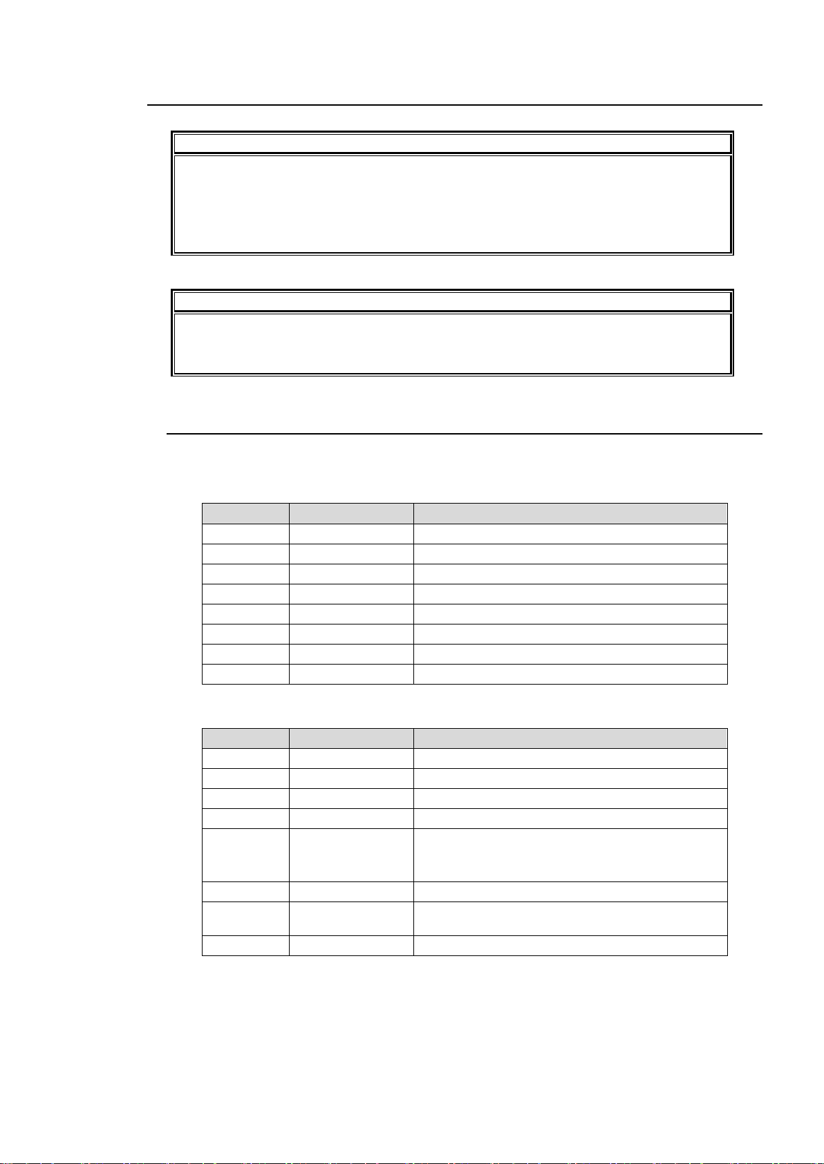
2-3. Internal Settings
IMPORTANT
Note that internal switch settings should not be changed from factory defaults. If you
have accidentally changed the settings, return them to the factory default settings as
shown in this section.
Be sure to have qualified technical personnel perform the settings and adjustments in
the interior, or contact your dealer.
CAUTION
Do not access any internal cards while the unit is powered ON. Always power OFF all
connected units / disconnect power cords prior to accessing the interior. To protect
boards from electrostatic damage, do not touch the components on the boards.
Pin No.
Default setting
Setting
1
OFF
Do not change.
2
OFF
Do not change.
3
OFF
Do not change.
4
OFF
Do not change.
5
OFF
Do not change.
6
OFF
Do not change.
7
OFF
Do not change.
8
OFF
Do not change.
Pin No.
Default setting
Setting
1
OFF
Do not change.
2
OFF
Do not change.
3
OFF
Do not change.
4
OFF
Do not change.
5
OFF
If the FA-95DACBL is installed in SLOT A: OFF
If the FA-95DACBL is installed in SLOT B: ON
If the FA-95DACBL is not installed: OFF
6
OFF
Do not change.
7
OFF
Standard FA-9520: OFF (without FA-95PS)
If the FA-95PS is installed: ON
8
OFF
Do not change.
2-3-1. Dipswitch Settings
The following settings can be made at the dipswitches on MAIN CARD inside the unit.
Dipswitch S1 Settings
Dipswitch S2 Settings
21
Page 22
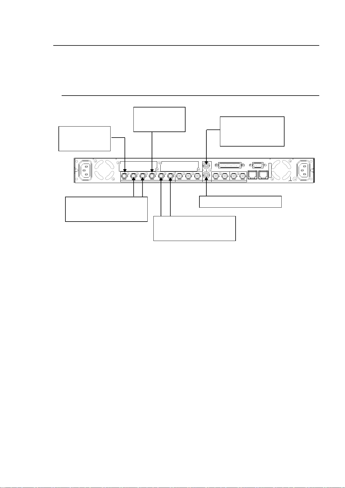
3. Connections
AC100 - 240V 50/60 Hz IN 1
FAN2
SER. NO.
LAN2LAN1
REMOTE
DIGITAL AUD IO IN / OU T
7 / 85 / 63 / 41 / 2
ANALOG AUDIO
GENLOCK IN
COMPOSITE
OUT2OUT1INBOUT4OUT3IN2OUT2OUT1
SDI
IN1
A
FAN1
AC100 - 240V 50/60 Hz IN2
Terminate at 75 ohm if not used.
Reference signal
(BB or Tri-level sync signal
synchronized with the input
signal.)
Input an HD/SDSDI signal to SDI
IN1.
Outputs the SDI IN1 input signal
synchronized with the SDI OUT1
and 2 reference signal.
Outputs the SDI IN2 input signal
synchronized with the reference
signal from SDI OUT3 and 4.
Input an HD/SDSDI signal to SDI
IN2.
This section describes the connections and settings for specific usages. The descriptions on the
settings are based on the factory default. If you are not sure of your current settings, you can reset
the unit to the default setting by selecting DEFAULT in the EVENT LOAD menu described in the
section 8-1 “EVENT LOAD”.
3-1. For 2-Channel Frame Synchronizer Use
Settings that need to be checked:
Set FS1 INSEL to SDI1 in the FS INPUT SELECT menu (see section 5-6-1).
Set FS2 INSEL to SDI2 in theFS INPUT SELECT menu (see section 5-6-1).
Set SDI1/2 to FS1 in the OUTPUT ASSIGN menu (see section 5-7-1).
Set SDI3/4 to FS2 in the OUTPUT ASSIGN menu (see section 5-7-1).
Adjust phase and position to match the reference signal in HD PHASE SET to VIDEO
POSITION menus if necessary (see sections 5-9-2 to 5-9-4).
22
Page 23
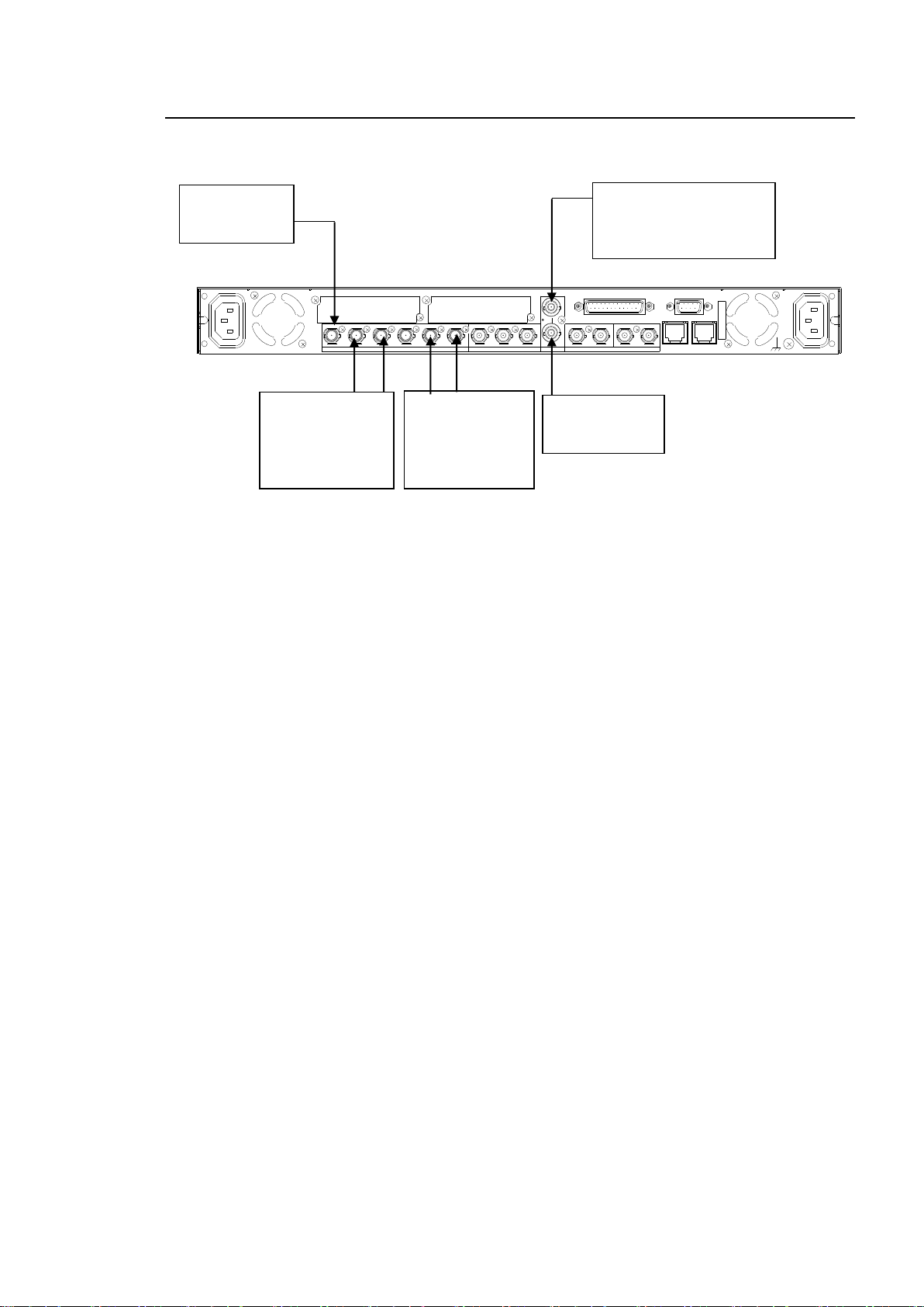
3-2. For HD/SD-SDI Simul Output
AC100 - 240V 50/60 Hz IN 1
FAN2
SER. NO.
LAN2LAN1
REMOTE
DIGITAL AUD IO IN / OU T
7 / 85 / 63 / 41 / 2
ANALOG AUDIO
GENLOCK IN
COMPOSITE
OUT2OUT1INBOUT4OUT3IN2OUT2OUT1
SDI
IN1
A
FAN1
AC100 - 240V 50/60 Hz IN2
Reference signal
(BB or Tri-level sync signal
synchronized with the input
signal.)
Terminate at 75
ohm if not used.
Input an HD/
SD-SDI signal
to SDI IN1.
Outputs an
HD-SDI signal
synchronized with
the reference
signal from SDI
OUT1 and 2.
Outputs an
SD-SDI signal
synchronized with
the reference
signal from SDI
OUT3 and 4.
It is possible to always output HD-SDI signal from SDI OUT1/2, and SD-SDI signal from SDI
OUT3/4 regardless of whether the input signal is HD or SD-SDI.
Settings that need to be checked:
Set FS1 IN SEL to SDI1 in the FS INPUT SELECT menu (see section 5-6-1).
Set FS2 IN SEL to SDI2 in theFS INPUT SELECT menu (see section 5-6-1).
Set SDI1/2 to FS1 in the OUTPUT ASSIGN menu (see section 5-7-1).
Set SDI3/4 to FS2 in theOUTPUT ASSIGN menu (see section 5-7-1).
Set FS1 conversion mode (CONV) to 1080i or an HD format such as 720p in the CONV
MODE menu (see section 5-3-1).
Set FS1 ASPECT to 16:9 P 4:3 in the CONV MODE menu (see section 5-3-1).
Set FS1 SD ASPECT to 4:3 in the VIDEO INPUT SET menu (see section 5-6-2).
Set FS2 conversion mode (CONV) to SD in the CONV MODE menu (see section 5-3-1.)
Set FS2 ASPECT to 4:3 F 4:3 in the CONV MODE menu (see section 5-3-1).
* Change ASPECT and/or SD ASPECT settings if necessary.
23
Page 24
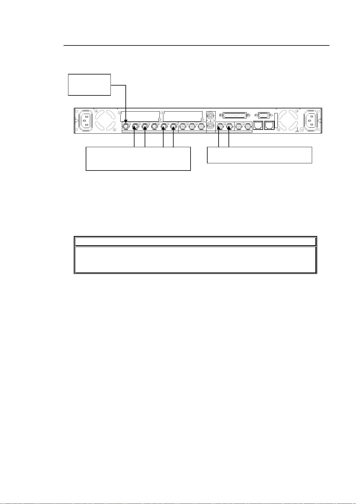
3-3. To Embed AES Input Signals on SDI Signals
NOTE
Change, if necessary, audio settings in the AES AUDIO Settings (AES AUDIO)
(section 6-2) and/or AUDIO DELAY Settings (section 6-6), and/ or the SRC mode
setting in the EMB1 SRC MODE menu (section 6-9-1).
AC100 - 240V 50/60 Hz IN 1
FAN2
SER. NO.
LAN2LAN1
REMOTE
DIGITAL AUD IO IN / OU T
7 / 85 / 63 / 41 / 2
ANALOG AUDIO
GENLOCK IN
COMPOSITE
OUT2OUT1INBOUT4OUT3IN2OUT2OUT1
SDI
IN1
A
FAN1
AC100 - 240V 50/60 Hz IN2
Input an HD/
SD-SDI signal
to SDI IN1.
Input AES signals to DIGITAL AUDIO IO
1/2, and IO3/4.
The AES signals are embedded to
AUDIO CH 1 through 4 of output signals
from SDI OUT1 and 2.
The following describes how to embed 4 channel AES signals on SDI signals in SDI OUT 1 and
2 output signals
Settings that need to be checked:
Set FS1 IN SEL to SDI1 in the FS INPUT SELECT menu (see section 5-6-1).
Set SDI 1/2 to FS1 in the OUTPUT ASSIGN menu (see section 5-7-1).
Set CH1 through CH4 to AES CH1 through CH4, respectively, in the EMB1 OUT REMAP
menu (see section 6-5-1).
24
Page 25
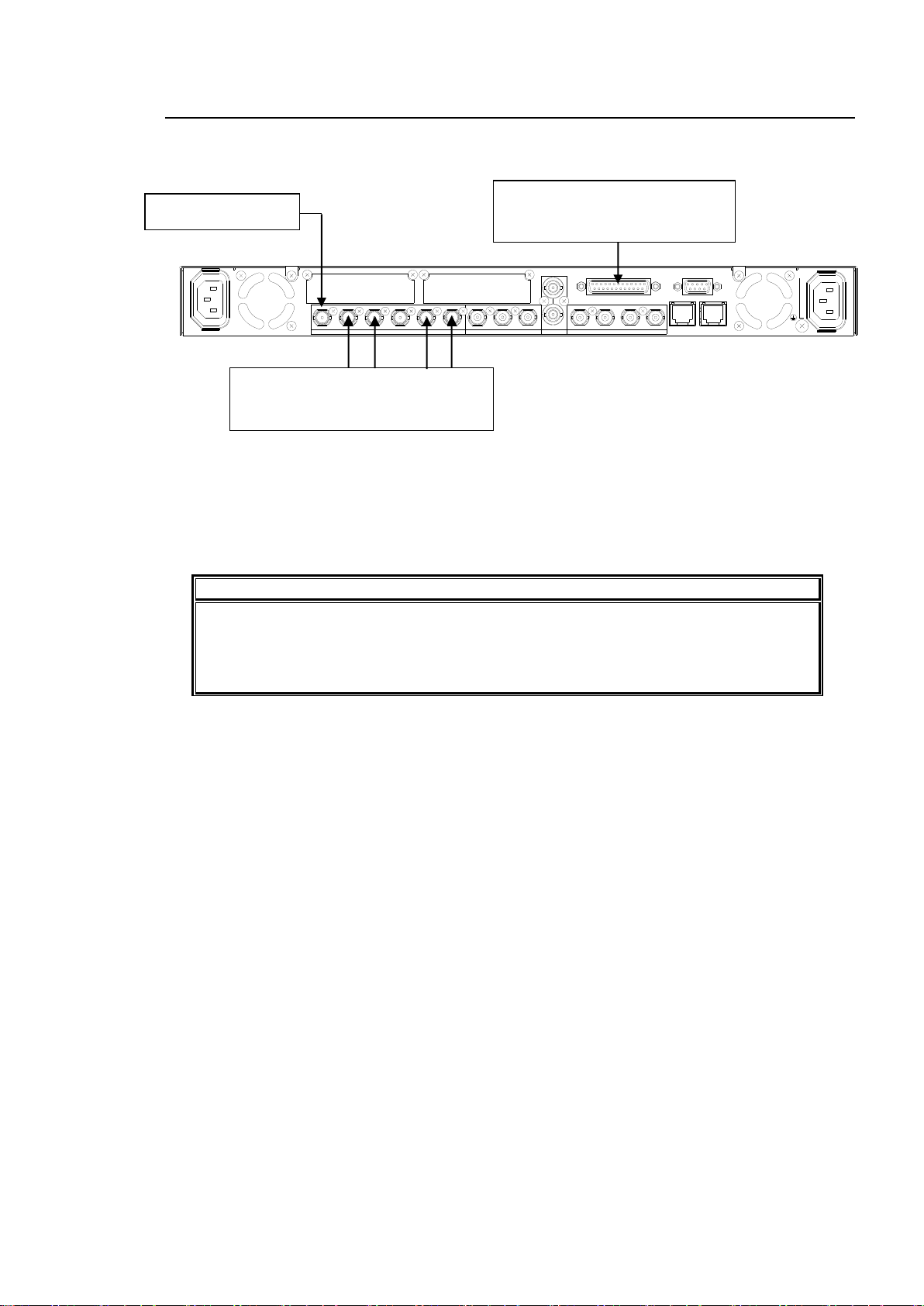
3-4. To Embed Analog Audio Signals on SDI Signals
NOTE
See section 12 "Analog Audio Connection” for the ANALOG AUDIO connector
connection.
Change audio settings, if necessary, in the ANALOG AUDIO Settings (ANALOG)
menu (section 6-3).
REMOTE
LAN1
COMPOSITE
OUT3OUT2IN1
SDI
ANALOG AUDIO
LAN2
IO1/2
DIGITAL AUDIO
OUT4OUT1 IN2
FAN2
IO3/4
IO5/6
IO7/8
GENLOCK IN
FAN1
OUT1 OUT2IN
Input audio signals to ANALOG
AUDIO IN1 - 4 channels.
The Analog audio signals are
embedded to AUDIO CH 1 through 4 of
output signals from SDI OUT1 and 2.
Input an HD/SD-SDI
signal to SDI IN1.
The following describes how to embed a 4- channel analog audio signal on SDI OUT1 and 2
output signals.
Settings that need to be checked:
Set FS1 IN SEL to SDI1 in the FS INPUT SELECT menu (see section 5-6-1).
Set SDI 1/2 to FS1 in the OUTPUT ASSIGN menu (see section 5-7-1).
Set CH1 through CH4 to ANALOG CH1 through CH4 respectively in the EMB1 OUT REMAP
menu (see section 6-5-1).
25
Page 26
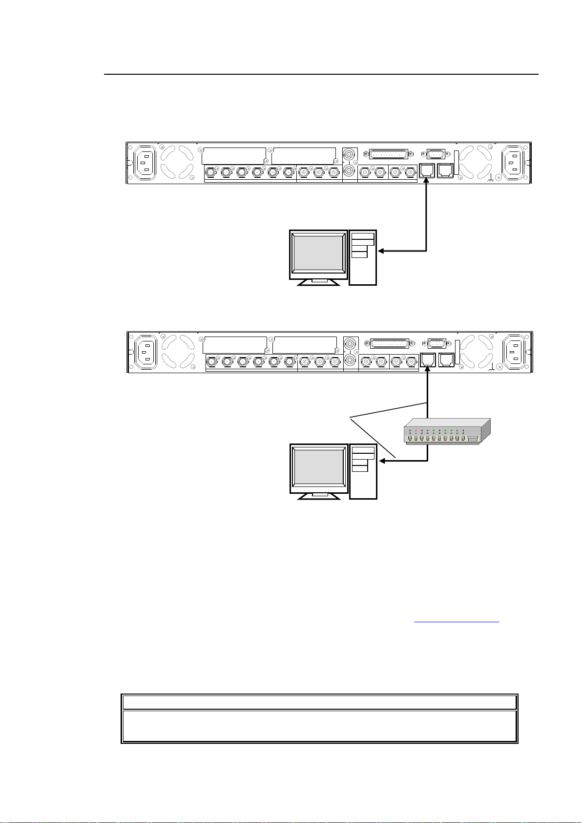
3-5. Connecting a Computer
NOTE
The FA-9520’s IP address can be checked on the front panel display. See section 7-7
“NETWORK INFO” for details.
AC100 - 240V 50/60 Hz IN 1
FAN2
SER. NO.
LAN2LAN1
REMOTE
DIGITAL AUD IO IN / OU T
7 / 85 / 63 / 41 / 2
ANALOG AUDIO
GENLOCK IN
COMPOSITE
OUT2OUT1INBOUT4OUT3IN2OUT2OUT1
SDI
IN1
A
FAN1
AC100 - 240V 50/60 Hz IN2
PC
Crossover
LAN cable
LAN1
AC100 - 240V 50/60 Hz IN 1
FAN2
SER. NO.
LAN2LAN1
REMOTE
DIGITAL AUD IO IN / OU T
7 / 85 / 63 / 41 / 2
ANALOG AUDIO
GENLOCK IN
COMPOSITE
OUT2OUT1INBOUT4OUT3IN2OUT2OUT1
SDI
IN1
A
FAN1
AC100 - 240V 50/60 Hz IN2
Straight-through
LAN cable
PC
LAN1
The FA-9520 can be controlled from a computer through a Web browser.
Connect a computer to the FA-9520 as shown below.
Connection using a crossover LAN cable.
Connection using a hub
The FA-9520 network settings must be adjusted for your network after purchase.
The FA-9520’s LAN1 IP address is set to 192.168.0.10 at the factory.
Set the IPaddress and subnet mask of the computer.
IP address: 192.168.0.1 to 192.168.0.254 (except 192.168.0.10)
Subnet mask: 255.255.255.0
In Windows, open the Local Area Connection Properties dialog box, and open the Internet
Protocol (TCP/IP) Properties window. The settings must be made in the window. See the
user’s manual of your computer for details.
Start a web browser on your computer, and enter the address as http://192.168.0.10.
Enter the default user name (fa9520), and the default password (foranetwork).
The FA-9520 control window appears on the web browser window.
See section 9-8 “Network Settings” for details on changing the FA-9520’s IP address.
See section 9 “Control via WEB Browser” for details on the FA-9520 web browser control
window.
26
Page 27
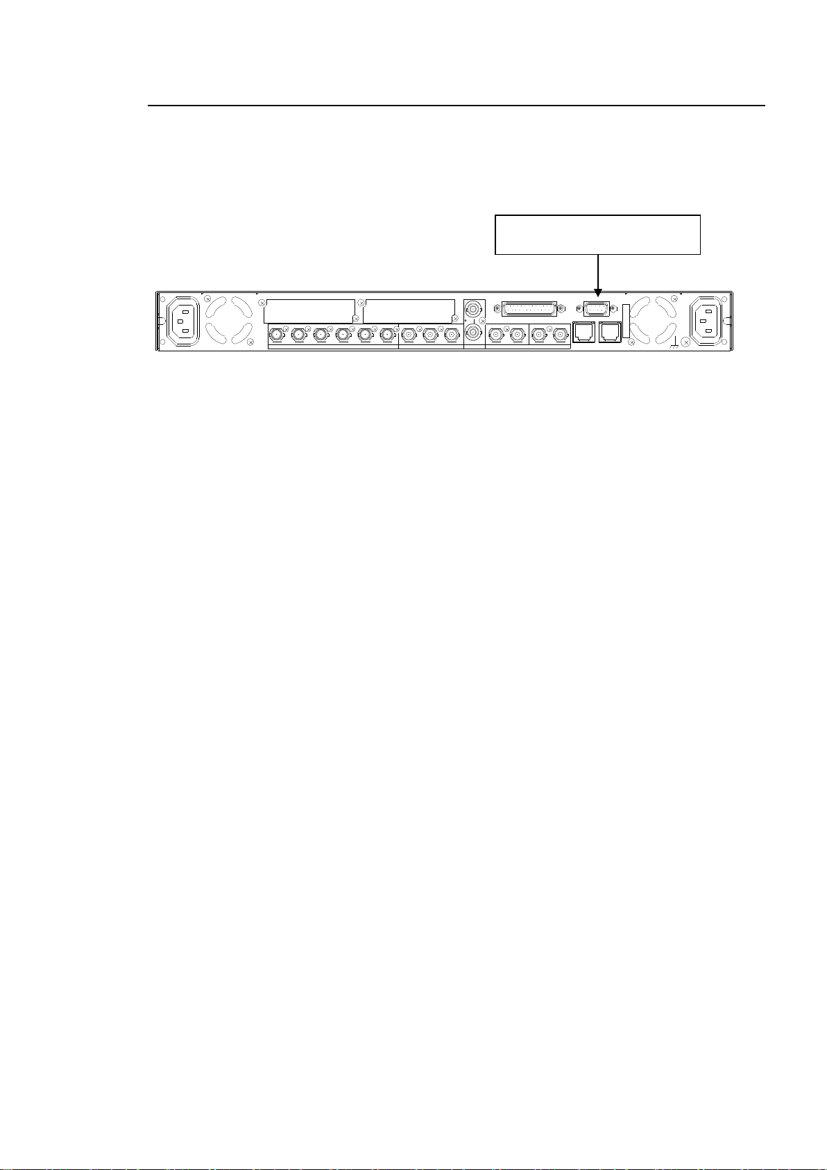
3-6. Connecting to the REMOTE (GPI) Connector
AC100 - 240V 50/60 Hz IN 1
FAN2
SER. NO.
LAN2LAN1
REMOTE
DIGITAL AUD IO IN / OU T
7 / 85 / 63 / 41 / 2
ANALOG AUDIO
GENLOCK IN
COMPOSITE
OUT2OUT1INBOUT4OUT3IN2OUT2OUT1
SDI
IN1
A
FAN1
AC100 - 240V 50/60 Hz IN2
Connect a device to the REMOTE
connector.
Easy control over the FA-9520 from an external device is also possible by connecting the device
to the REMOTE connector.
Seven ports are provided on the connector. Assign functions to the respective ports to control the
FA-9520.
See section 14 “REMOTE” for details on pin assignments and triggers.
See section 7-6 “GPI SETTING” for details on function assignments for the ports.
27
Page 28
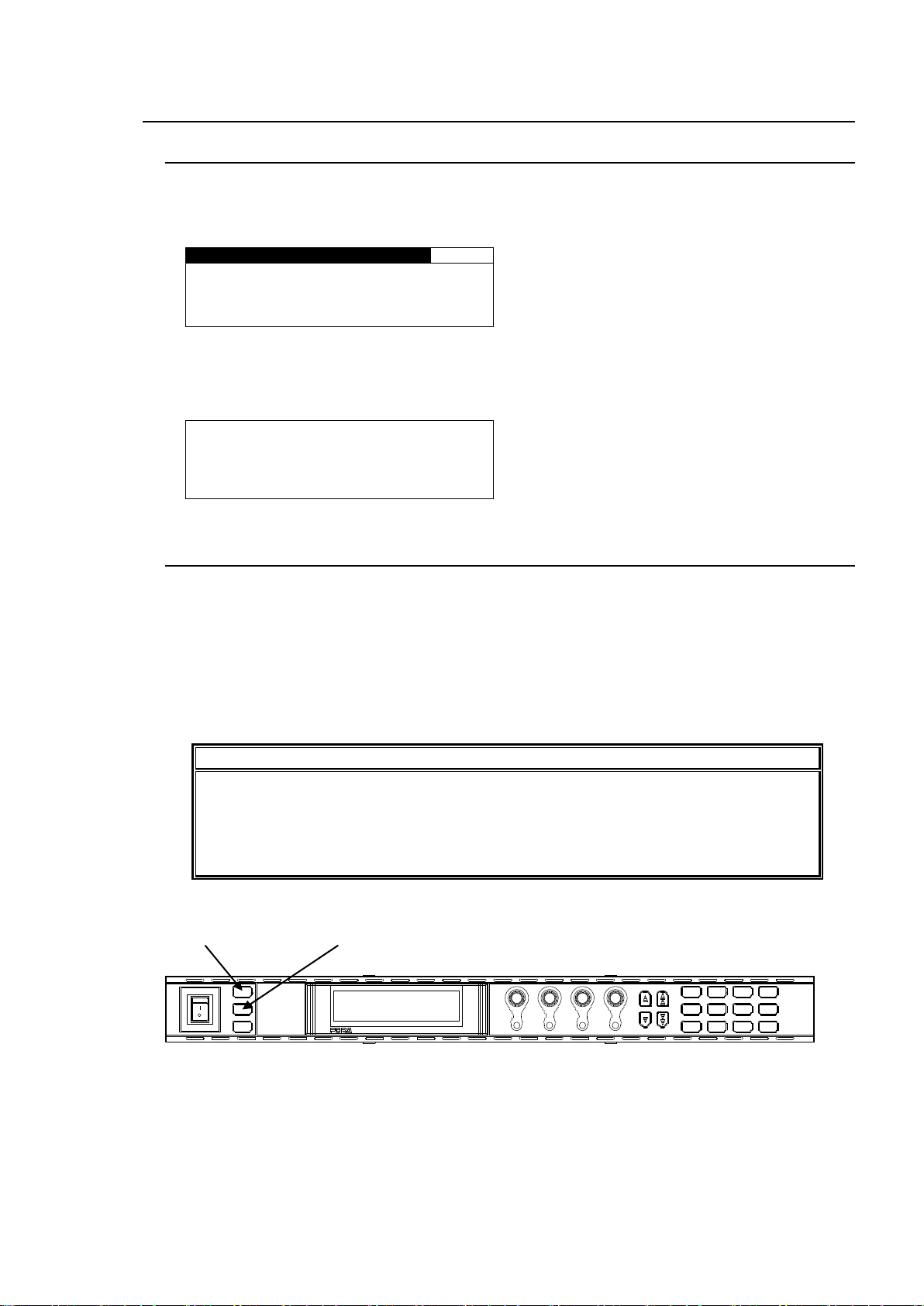
4. Front Panel Operation
V I D E O I N S T A T US
502
S D I 1 : 1 0 8 0 / 5 9 i
S D I 2 : 5 2 5 / 6 0
C O M P O S I T E : 5 2 5 / 6 0
R E F E R E N C E : 5 2 5 / 6 0
L O A D I N G L O G O D A T A . . .
0 0 % C O M P L E T E
IMPORTANT
Make sure that the FS1/LOCK and FS2/LOCK button LEDs are lit green or unlit before
starting an operation. If FS1/LOCK and/or FS2/LOCK button LED(s) are lit orange, all
operations on the front panel for FS1 and/or FS2 except the LOCK button(s) are
disabled. Press and hold the FS1/LOCK and/or FS2/LOCK button(s) that are lit
orange to unlock the operations.
POWER
ON
OFF
PS1/LOCK
PS2/LOCK
EVENT
VIDEO IN
GENLOCL
REMOTE
AUDIO IN
FAN ALARM
DC POWER
F 1
F 2
F 3
F 4
F A - 9 5 2 0HD / S D F R A ME S YN C HR O NI Z E R
DISPLAY
F 1
UNITY
F 2
UNITY UNITY
F 3
F 4
UNITY
PROCESS
SDI AUDIO
MAPPING
VIDEO OP
AUDIO OP
C C
A V O CLIP
DELAY
VIDEO SYS
AUDIO SYS
AES AUDIO
CONV1
ANALOG
IN SEL
DOWNMIX
STATUS
OTHER
CONV2
MASTER
OUT SEL
MOD E
VIDEO
AUDIO
FS1/LOCK button
FS2/LOCK button
4-1. Powering ON
Turn the power ON after all system connections are complete. The indicators on the front panel
light up during startup. When startup is complete, the indicators will go off and the VIDEO IN
STATUS menu showing the current input video and reference signal formats will be displayed.
If Logo data is stored:
A loading progress message is displayed in the menu display as shown below.
Logo data may take up to 2.5 minutes to load.
4-2. Basic Operation
This section explains how to select menus and parameters.
Most of the menus can be controlled by these basic operations. However, some menus work
differently. See the descriptions given for each menu for details.
The FA-9520 has two modes for the menu operation: NORMAL mode, in which setting changes
immediately take effect, and LIVE SAFE mode, in which some settings request confirmation
before changes take effect. NORMAL and LIVE SAFE modes can be selected in the FRONT
OPERATION menu (sec. 7-4). Factory default is NORMAL mode. Menus that request a setting
confirmation are shown in the menu list in section 4-2-2. “Menu Buttons” with a black circle (●).
28
Page 29
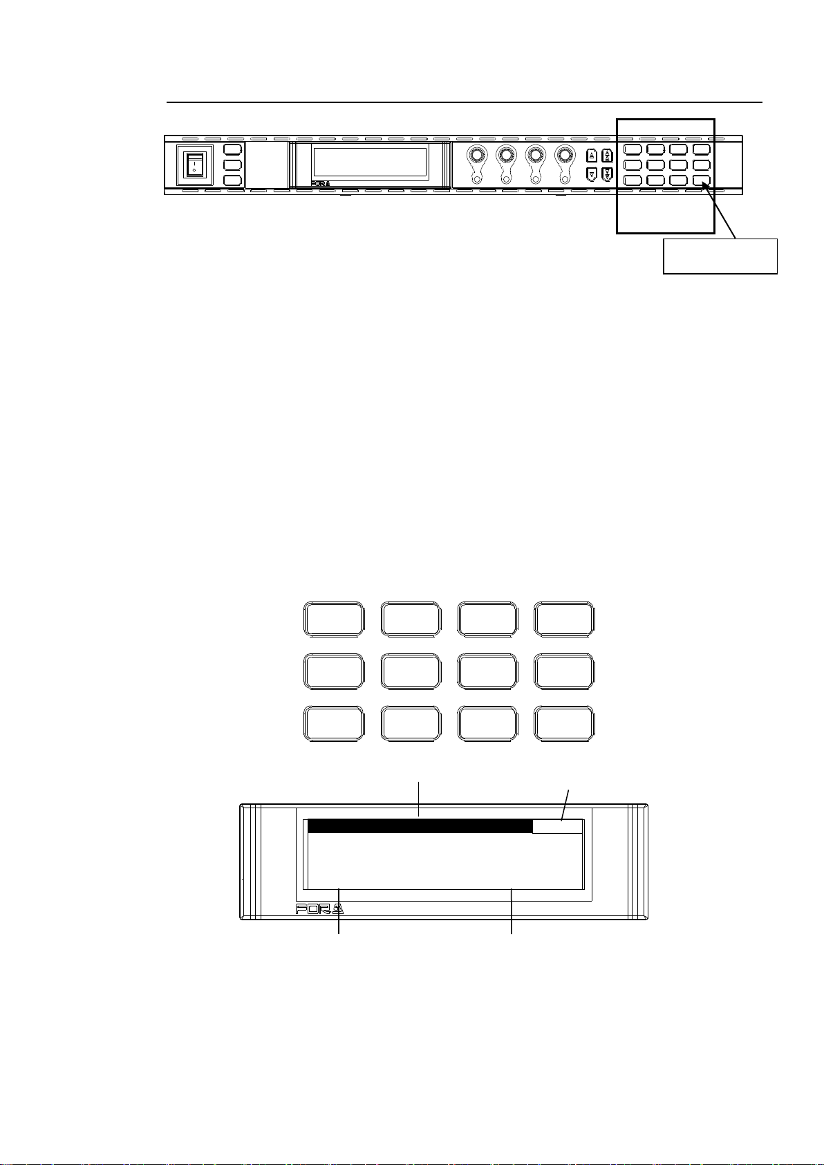
4-2-1. Accessing Menus
V I D E O P R O C A M P
1
V I D E O L E V E L : 1 0 0 . 0 %
C H R O M A L E V E L : 1 0 0 . 0 %
S E T U P / B L A C K : 0 . 0 %
H U E : 0 . 0 °
MASTER
CONV2
OUT SEL
MODE
VIDEO
AUDIO
ANALOG
CONV1
IN SEL
DOWNMIX
STATUS
OTHER
C C
AES AUDIO
CLIP
DELAY
AUDIO SYS
VIDEO SYS
AUDIO OP
VIDEO OP
MAPPING
A V O
PROCESS
SDI AUDIO
POWER
ON
OFF
PS1/LOCK
PS2/LOCK
EVENT
VIDEO IN
GENLOCL
REMOTE
AUDIO IN
FAN ALARM
DC POWER
F 1
F 2
F 3
F 4
F A - 9 5 2 0HD / S D F R A ME S YN C HR O NI Z E R
DISPLAY
F 1
UNITY
F 2
UNITY UNITY
F 3
F 4
UNITY
PROCESS
SDI AUDIO
MAPPING
VIDEO OP
AUDIO OP
C C
A V O CLIP
DELAY
VIDEO SYS
AUDIO SYS
AES AUDIO
CONV1
ANALOG
IN SEL
DOWNMIX
STATUS
OTHER
CONV2
MASTER
OUT SEL
MOD E
VIDEO
AUDIO
Menu buttons
VIDEO/AUDIO
button
Parameter
Menu Title
Value
Page number
F 1
F 2
F 3
F 4
F A - 9 5 2 0HD / SD FRAM E S Y NCHRONI ZER
Every press of the VIDEO/AUDIO button alternates the menu button assignments between
video menus and audio menus. The button indicators light up green when the buttons are
accessible to video menus that are indicated on the top row of each menu button. They light
up orange when they are accessible to audio menus that are indicated on the bottom row of
each menu button.
Pressing a menu button displays the corresponding menu on the menu display. Menus are
divided into categories. The single-arrow buttons allow you to move between menus if the
selected menu button has multiple menu pages in the category. The single-arrow button lights
up when there are more menus to be accessed in the direction. If the single-arrow button is
unlit, the direction is not accessible.
The double-arrow buttons allow you to go to the first menu of the menu button.
The FS1/LOCK or FS2/LOCK button lights green as well as the selected VIDEO button for
menus in which settings can be set for FS1 and FS2 separately. If the FS1/LOCK button is
pressed and lit green, settings for FS1 are enabled. Settings for FS2 are enabled in the same
manner. These menus are described in the menu list in section 4-2-2 “Menu Buttons”.
Menu Buttons
In the example above, the PROCESS/SDI AUDIO button has been pressed, so that the
VIDEO PROC AMP menu is displayed.
29
Page 30
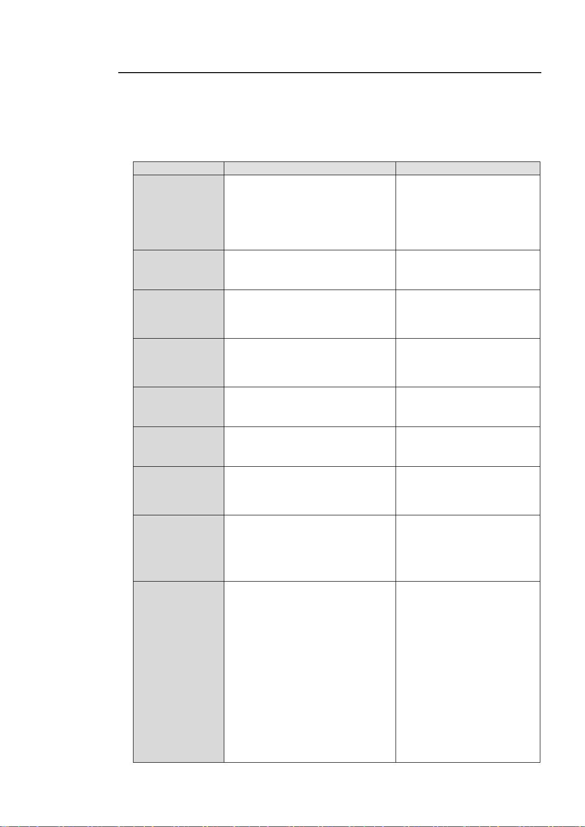
4-2-2. Menu Buttons
Menu Button
VIDEO menus (lit green)
AUDIO menus (lit orange)
PROCESS
SDI AUDIO
⊚VIDEO PROC AMP
EMB1 IN GAIN
EMB1 OUT MONO
● EMB1 IN SET
● EMB1 OUT CLOCK
EMB2 IN GAIN
EMB2 OUT MONO
● EMB2 IN SET
● EMB2 OUT CLOCK
CC
AES AUDIO
⊚WHITE LEVEL
⊚BLACK LEVEL
⊚GAMMA LEVEL
COLOR CORRECT
AES IN GAIN
AES HYSTERESIS
AES OUT MONO
● AES I/O SETUP *3
CONV1
ANALOG
● CONV MODE
CONV SIZE/POS
CONV CROPPING
CONV IMPROVE
CONV SIDE RGB
ANALOG IN LEVEL
ANALOG IN GAIN
ANALOG OUT LEVEL
ANALOG OUT MONO
● ANALOG IN SYSTEM
CONV2
MASTER
Not functioning
MASTER OUT GAIN
EMB1 OUT GAIN
EMB2 OUT GAIN
AES OUT GAIN
ANALOG OUT GAIN
AVO
MAPPING
●AVO SETTING
USER1-5 LEVEL SET
USER1-2 AREA SET
AVO SETUP
*1
● EMB1 OUT REMAP
● EMB2 OUT REMAP
● AES OUT REMAP
● ANALOG OUT REMAP
CLIP
DELAY
YPbPr/RGB CLIP
COMPOSITE CLIP
EMB1 IN DELAY
EMB2 IN DELAY
AES IN DELAY
ANALOG IN DELAY
IN SEL
DOWN MIX
● FS INPUT SELECT
ANC DETECT LINE
ANC DETECT SEL
● AIO A IN MODE *1
● AIO B IN MODE *2
● DOWN MIX1 SET
● DOWN MIX1 ASSIGN
● DOWN MIX2 SET
● DOWN MIX2 ASSIGN
OUT SEL
MODE
● OUTPUT ASSIGN
● AIO A ASSIGN *1
● AIO B ASSIGN *2
ANC DATA EMBED
ANC EMBED LINE
● EMB1 SRC MODE
● EMB2 SRC MODE
● AES SRC MODE
● EMB1 POLARITY
● EMB2 POLARITY
● AES POLARITY
● ANALOG POLARITY
VIDEO OP
AUDIO OP
LOGO SELECT
KEYER SET
● Dolby AUX OUT A
*6*8
● Dolby DEC IN A
*6*8
● Dolby DEC REF A
*6*8
● Dolby DOWNMIX A
*6*8
Dolby DEC GAIN A
*6*8
● Dolby ENC INPUT A*8
● Dolby ENC SET A*8
● METADATA INPUT
*8
◇LOUD MEASURE 1A
*4
LOUD CTRL ENA1A
*4
LOUD CTRL SET1A
*4
LOUD CH ASGN1A
*4
◇LOUD MEASURE 2A
*4
LOUD CTRL ENA2A
*4
LOUD CTRL SET2A
*4
LOUD CH ASGN2A
*4
◇
● Dolby AUX OUT B
*7*9
● Dolby DEC IN B
*7*9
● Dolby DEC REF B
*7*9
● Dolby DOWNMIX B
*7*9
The VIDEO/AUDIO button at the bottom right switches between the video and audio-related
menus. Pressing the button alternates the button to work as video menu buttons (lit green)
and audio menu buttons (lit orange). The menus at the top of each button label are video
menus (lit green), and the menus at the bottom are audio menus (lit orange). Menus that
request a setting confirmation in LIVE SAFE mode are shown with a black circle (●) in the
following list.
30
Page 31

Menu Button
VIDEO menus (lit green)
AUDIO menus (lit orange)
VIDEO OP
AUDIO OP
LOGO SELECT
KEYER SET
Dolby DEC GAIN B
*7*9
● Dolby ENC INPUT B*9
● Dolby ENC SET B*9
● METADATA INPUT B
*9
LOUD MEASURE 1B
*5
LOUD CTRL ENA1B
*5
LOUD CTRL SET1B
*5
LOUD CH ASGN1B
*5
◇LOUD MEASURE 2B
*5
LOUD CTRL ENA2B
*5
LOUD CTRL SET2B
*5
LOUD CH ASGN2B
LOUD STANDARD
*4 *5
VIDEO SYS
AUDIO SYS
● FS MODE SET
HD PHASE SET
SD PHASE SET
VIDEO POSITION
FREEZE SET
● ANC SET
ANC LOSS SET
WSS AFD ERROR
AUDIO GRP
TEST SIGNAL
● BY-PASS SETTING
SD LINE MASK
COMPOSITE SET1
● COMPOSITE SET2
● FADE IN/OUT
● DIGITAL AUDIO
● AUDIO ERR SENSE
● DIGITAL SILENCE
STATUS
OTHER *5
UNIT ALARM
VIDEO IN STATUS
VIDEO OP INPUT
*1*2
VIDEO OUT STATUS
VIDEO OP OUTPUT
*1*2
AUDIO IN DETECT1
AUDIO IN DETECT2
AUDIO OUTPUT1
AUDIO OUTPUT2
EMB1 IN AUDIO CH1 to 16
EMB2 IN AUDIO CH1 to 16
AES IN AUDIO CH1 to 8
ANALOG IN AUDIO CH1 to 4
SDI1/2 OUT AUDIO CH1 to 16
SDI3/4 OUT AUDIO CH1 to 16
AES OUT AUDIO CH1 to 8
ANALOG OUT AUDIO CH1 to 4
Dolby OP A AUX
*6*8
Dolby OP B AUX
*7*9
AFD IN STATUS
ANC IN STATUS
ANC IN STATUS1 to 2
ANC OUT
S2016 OUT
VI OUT
WSS OUT
ANC OUT1
FS1/FS2 COPY
MU OPERATION
● CONTROL SETTING
FRONT OPERATION
FRONT PANEL SET
GPI SETTING
NETWORK INFO
UNIT Ver.
OPTION A Ver.
OPTION B Ver.
OTHER OPTION
SOFT OPTION1
SOFT OPTION2
VIDEO
AUDIO
VIDEO menus
AUDIO menus
*1 Shown if the optional FA-95AIO is installed in option slot A.
*2 Shown if the optional FA-95AIO is installed in option slot B.
*3 Hidden if the optional FA-95DACBL is installed.
*4 Shown if the optional FA-95ALA is installed in option slot A.
*5 Shown if the optional FA-95ALA is installed in option slot B.
*6 Shown if the optional FA-95D-D is installed in option slot A.
*7 Shown if the optional FA-95D-D is installed in option slot B.
*8 Shown if the optional FA-95DE-E is installed in option slot A.
*9 Shown if the optional FA-95DE-E is installed in option slot B.
Can be navigated to using double (up and down) arrow buttons. “ “ is not shown in the menu
display.
⊚ Settings for FS1 and FS2 can be selected or verified separately using the FS1 or FS2 button. ⊚
Can change settings for FS1 and FS2 simultaneously in LINK mode. “ “ and “⊚” are not shown in
the menu display.
● When changed in LIVE SAFE mode, single (up and down) arrow buttons and the LED around the
control knob of which setting is changed blink confirming the setting change. To set the FA-9520 to
LIVE SAFE mode, change the mode setting referring to section 7-4. “FRONT OPERATION”. “● “ is
not shown in the menu display.
31
Page 32
4-2-3. Arrow Buttons
IMPORTANT
NORMAL and LIVE SAFE modes can be switched in the FRONT OPERATION menu
(see section 7-4).
Double-arrow buttons (up and down)
<NORMAL mode>
The double-arrow buttons allow you to go to the first menu of the video or audio menus that
are assigned to the respective menu buttons or first menus of major setting menus
(designated by “” in the above menu list).
<LIVE SAFE mode>
Button functions are the same as NORMAL mode, however, double-arrow buttons are
inoperative while single-arrow buttons are blinking (indicating the FA-9520 is in the setting
change confirming state, because a parameter in one of the menus requiring a setting change
confirmation has been changed).
Single-arrow buttons (up and down)
< NORMAL mode>
The single-arrow buttons allow you to move between menus within the menus that are
assigned to respective menu buttons.
When it reaches the last menu, the light goes off.
< LIVE SAFE mode>
Single-arrow buttons blink when a parameter in one of the menus requiring a setting change
confirmation is changed. To confirm the change, press the single down arrow button. Pressing
the single up arrow button cancels the change, and the parameter before change will be
displayed.
While single-arrow buttons are blinking, all buttons except single-arrow buttons are disabled
until either single-arrow button is pressed.
Menus that request a setting confirmation are shown with a black circle (●) in the menu list in
section 4-2-2. “Menu Buttons”.
4-2-4. Consecutive Viewing of Settings
<NORMAL mode>
While a menu button is turned on, the menu display will be in consecutive display mode when
both single (up and down) arrow buttons are pressed simultaneously. Both single arrow
buttons blink when they are in consecutive display mode. To exit the mode, simultaneously
press both arrow buttons again. Then arrow buttons will stop blinking.
The single down and up arrow buttons, while in consecutive display mode, can consecutively
display all menus in which menu list settings can be changed, from the first to last or last to
first menu item. Meanwhile, holding down the single down or up arrow button also allows you
to consecutively view menus.
<LIVE SAFE mode>
Button functions are the same as NORMAL mode, however, consecutive display mode is
inoperative while single-arrow buttons are blinking (indicating the FA-9520 is in the setting
change confirming state, because a parameter in one of the menus requiring a setting change
confirmation has been changed). Consecutive display mode will be canceled when a setting
is changed.
Order of Consecutive Menu Display
VIDEO Menus (Lit green)
The single down-arrow button consecutively displays menu pages from VIDEO PROC AMP
of PROCESS to ANC OUT1 of STATUS in the menu list in section 4-2-2. On the other hand,
the single up-arrow button consecutively displays menu pages from ANC OUT1 of STATUS to
VIDEO PROC AMP of PROCESS in the menu list.
32
Page 33
AUDIO Menus (Lit orange)
Button mode
Button
Destination
Reference
VIDEO
CONV1
ANC SET(66)
5-9-6
VIDEO
CONV2
AFD IN STATUS(601)
5-10-20
VIDEO
IN SEL
VIDEO IN STATUS (502)
5-10-2
VIDEO
OUT SEL
VIDEO OUT STATUS (511)
5-10-4
AUDIO
SDI AUDIO
EMB1 IN AUDIO (551)
5-10-10
AUDIO
AES AUDIO
AES IN AUDIO(559)
5-10-12
AUDIO
ANALOG
ANALOG IN AUDIO(561)
5-10-13
AUDIO
AUDIO OP *1
Dolby OP A AUX (591) *1
or
Dolby OP B AUX (596) *1
5-10-18
5-10-19
VIDEO
AUDIO
The single down-arrow button consecutively displays menu pages from EMB1 IN GAIN of SDI
AUDIO to SOFT OPTION2 of OTHER in the menu list in section 4-2-2. On the other hand, the
single up-arrow button consecutively displays menu pages from SOFT OPTION2 of OTHER
to EMB1 IN GAIN of SDI AUDIO in the menu list.
* The EVENT button-assigned menus cannot be consecutively viewed. The consecutive
display mode is not supported for EVENT menus.
* While the menu display is in consecutive display mode, pressing the EVENT button
cancels the mode.
4-2-5. Page Jump Feature
Some menu buttons allow you to directly go to specific menus when they are held down for at
least 1 second. This feature helps you quickly check the state of specific settings.
*1 The Dolby OP A AUX (591) or B AUX (596) menu is available only if an FA-95D-D or
FA-95DE-E option is installed in option slot A or B. The page jump feature is inoperative
while the FA-9520 is in the setting change confirming state. It becomes operable once
the change is confirmed. Refer to section 4-2-6. “Changing Setting Values” for details.
33
Page 34
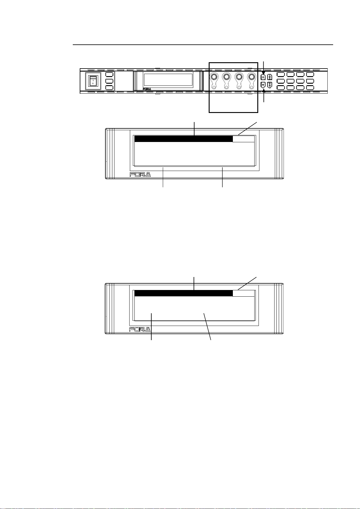
4-2-6. Changing Setting Values
V I D E O P R O C A M P
1
VIDEO LE V E L : 1 0 0 . 0 %
C H R O M A L E V E L : 1 0 0 . 0 %
S E T U P / B L A C K : 0 . 0 %
H U E : 0 . 0 °
FS I N P U T S E L E C T
47
FS1 I N S E L : S D I 1
F S 2 I N S E L : S D I 1
POWER
ON
OFF
PS1/LOCK
PS2/LOCK
EVENT
VIDEO IN
GENLOCL
REMOTE
AUDIO IN
FAN ALARM
DC POWER
F 1
F 2
F 3
F 4
F A - 9 5 2 0HD / S D F R AM E S Y N C HR ON I ZE R
DISPLAY
F 1
UNITY
F 2
UNITY UNITY
F 3
F 4
UNITY
PROCESS
SDI AUDIO
MAPPING
VIDEO OP
AUDIO OP
C C
A V O CLIP
DELAY
VIDEO SYS
AUDIO SYS
AES AUDIO
CONV1
ANALOG
IN SEL
DOWNMIX
STATUS
OTHER
CONV2
MASTER
OUT SEL
MOD E
VIDEO
AUDIO
Control
F1-F4
F 1
F 2
F 3
F 4
F A - 9 5 2 0HD / S D F RAM E S Y NCHRONI ZER
Parameter
Menu title
Setting value
Menu page number
F 1
F 2
F 3
F 4
F A - 9 5 2 0HD / S D F RAM E S Y NCHRONI ZER
Parameter
Menu title
Setting value
Menu page number
Once the desired menu is displayed, use the control knobs (F1-F4) to change the setting
values.
<NORMAL mode>
In the above example, the PROCESS/SDI AUDIO button has been pressed while the menu
buttons are turned to video menus (lit green) by pressing the VIDEO/AUDIO, so that the
VIDEO PROC AMP menu is displayed.
(If the LEDs around control F1 through 4 knobs are lit, the setting value corresponding to the
lit control knob can be changed.)
If you want to change the VIDEO LEVEL setting value, turn F1. To change the CHROMA
LEVEL setting value, turn F2. For SETUP/BLACK, turn F3, and for HUE turn F4. To go to
other menus assigned to the menu button, press the single-arrow down button. To return to
the previous menu, press the single-arrow up button.
<LIVE SAFE mode>
Menus that do not request a setting change confirmation (such as VIDEO PROC AMP) are
used the same as in NORMAL mode.
Menus that request a setting change confirmation (such as VIDEO INPUT SET) will be in the
setting change confirming state when the parameter is changed.
Example:
Pressing the IN SEL/DOWNMIX button while the button is in VIDEO menu selection mode (lit
green) will display the VIDEO INPUT SET menu (above figure).
To change the FS1 input video signal, turn F1. Turn F2 to change the FS2 input video signal.
If any setting is changed, single-arrow buttons and the control knob for the setting that has
changed will blink in the setting change confirming state. Pressing the single down arrow
button confirms the change and LEDs stop blinking, then light. Pressing the single up arrow
button cancels the change, the setting returns to before the change, and LEDs stop blinking,
then light.
While the FA-9520 is in a setting change confirming state, all buttons except single-arrow
buttons, control knobs F1 to F4 and their Unity buttons are disabled. To go to other menus,
press either single-arrow button to complete the confirmation.
34
Page 35
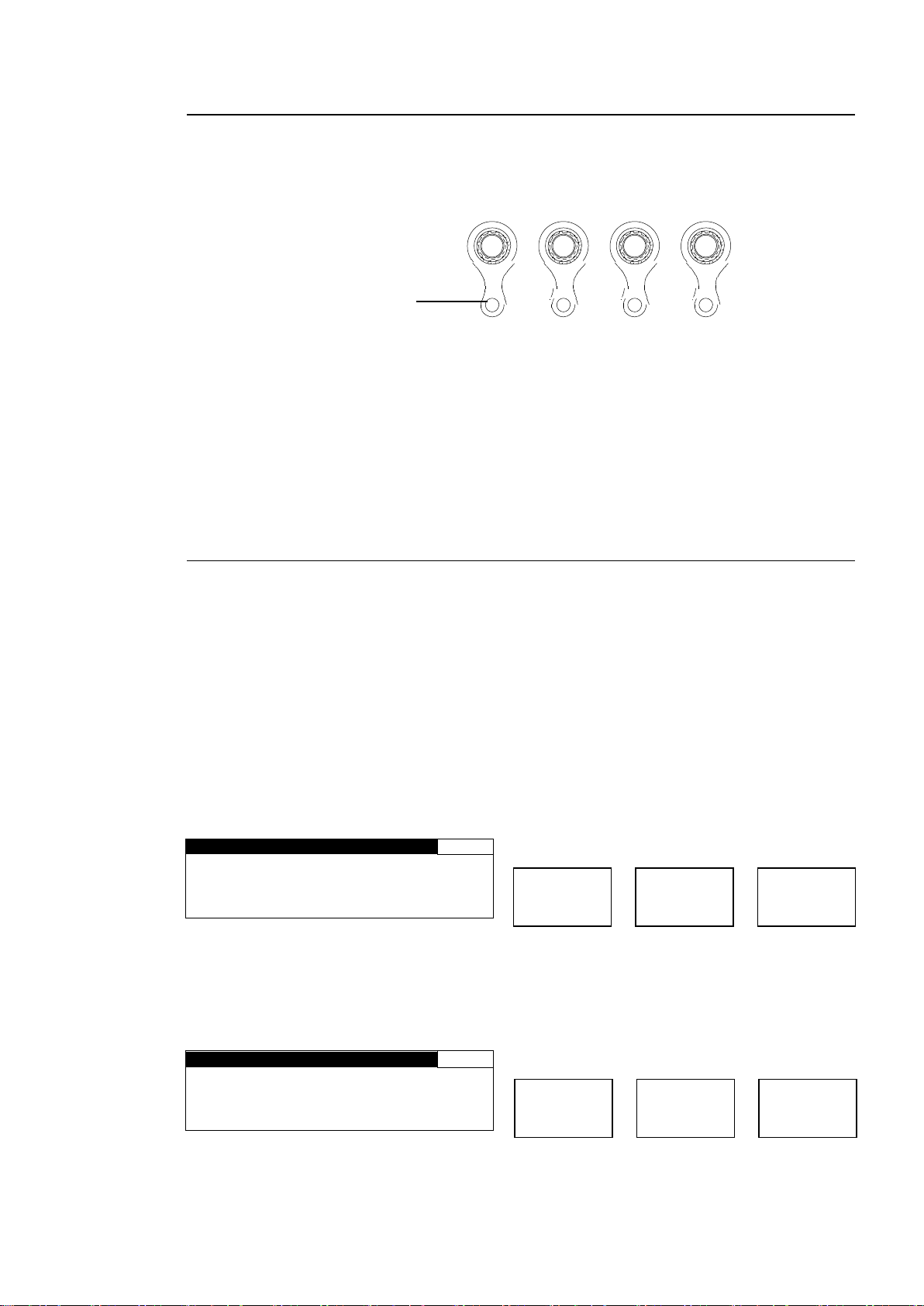
4-2-7. Resetting to Default
V I D E O P R O C A M P
1
V I D E O L E V E L : 1 0 0 . 0 %
C H R O M A L E V E L : 1 0 0 . 0 %
S E T U P / B L A C K : 0 . 0 %
HUE : 0 . 0 °
V I D E O P R O C A M P
1
V I D E O L E V E L : 1 0 0 . 0 %
C H R O M A L E V E L : 1 0 0 . 0 %
S E T U P / B L A C K : 0 . 0 %
HUE : 0 . 0 °
F1
F2
F3
F4
UNITY UNITY UNITY UNITY
Press the UNITY button to
reset the value. The indicator
lights up orange.
Menu button
PROCESS
SDI AUDIO
Lit green
FS1/LOCK
Unlit
FS2/LOCK
Menu button
PROCESS
SDI AUDIO
Unlit
FS1/LOCK
Lit green
FS2/LOCK
<NORMAL mode>
The UNITY indicator light goes off when the setting value is changed from the default value.
Pressing the UNITY button while the light is off returns the corresponding setting value to the
default value. Then the light goes off. Pressing the button again returns the value to the
previous value before resetting to the default value.
<LIVE SAFE mode>
The UNITY indicator light goes off when the setting value is changed from default. Pressing
the UNITY button while the light is off returns the corresponding setting value to default.
When a setting value is changed, the single-down-arrow button and the LED around the
control knob corresponding to the changed setting blinks in the setting change confirming
state. Pressing the single-down-arrow button while blinking confirms the change, and the
blinking arrow button and control knob lights turn on. Pressing the single-up-arrow button
cancels the change, the setting returns to the value before it was changed, and the blinking
arrow button and control knob lights turn on.
4-2-8. Switching Between 2-Channel Frame Synchronizers
Independent 2-channel frame synchronizers FS1 and FS2 can be switched to one from
another using the FS1/LOCK or FS2/LOCK button.
Menus that allow FS1 and FS2 setting selections are shown with or ⊚ in the menu list in
section 4-2-2. “Menu Buttons”.
Either the FS1/LOCK or FS2/LOCK button lights green in a menu that can be set for FS1 and
FS2 separately. The setting for the frame synchronizer corresponding to the lit button can be
changed.
Pressing both the FS1/LOCK and FS2/LOCK buttons simultaneously, for LINK setting menus
shown with ⊚ in the menu list in section 4-2-2. “Menu Buttons”, makes one button turn on and
light green, and the other blink. Changing settings for one frame synchronizer will also change
settings for the other.
Example 1: Setting VIDEO PROCESS AMP for FS1
1. Press the PROCESS/SDI AUDIO button to open the VIDEO PROCESS AMP menu. Press
the FS1/LOCK button for it to light green.
2. Turn F1 to F4 control knobs to change FS1 settings.
Example 2: Setting VIDEO PROCESS AMP for FS2
1. Press the PROCESS/SDI AUDIO button to open the VIDEO PROCESS AMP menu. Press
the FS2/LOCK button for it to light green.
2. Turn control knobs F1 to F4 to change FS2 settings.
35
Page 36
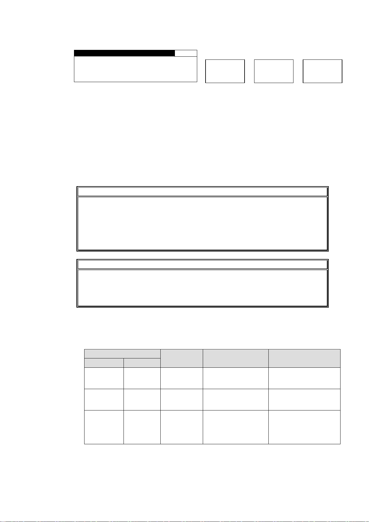
Example 3: Setting VIDEO PROCESS AMP for FS1 and FS2 simultaneously
V I D E O P R O C A M P
FS1
V I D E O L E V E L : 1 0 0 . 0 %
C H R O M A L E V E L : 1 0 0 . 0 %
SETU P / B L A C K : 0 . 0 %
HUE : 0 . 0 °
IMPORTANT
FS1 and FS2 cannot be changed simultaneously by pressing FS1/LOCK and
FS2/LOCK buttons at the same time in the following cases:
1. When the Color correction mode for either FS1 or FS2 is set to SEPIA. See
section 5-2-4. “COLOR CORRECT (C.C.)” for details on Color correction mode.
2. When FS1 AVO mode is set to AUTO or HOLD. See section 5-4-1 “AVO SETTING”
for details on AVO modes.
NOTE
In FS1/FS2 simultaneous setting mode, each control knob applies identical
adjustment values to both FS1 and FS2.
Menus supported for simultaneous setting mode are shown with “⊚” in the menu list in
section 4-2-2. “Menu Buttons”.
Button light color
Inhibition of
Setting procedure
Cancelling procedure
FS1/LOCK
FS2/LOCK
Orange
Green
FS1 settings
Hold down the
FS1/LOCK button > 3
sec.
Hold down the
FS1/LOCK button > 3
sec.
Green
Orange
FS2 settings
Hold down the
FS2/LOCK button >t
3 sec.
Hold down the
FS2/LOCK button > 3
sec.
Orange
Orange
Front panel
buttons
Hold down both
FS1/LOCK and
FS2/LOCK buttons >
3 sec for them to light
orange.
Hold down either the
FS1/LOCK or
FS2/LOCK button > 3
sec for either one to
lock.
Menu button
PROCESS
SDI AUDIO
Lit green
FS1/LOCK
Blinking green
FS2/LOCK
1. Press the PROCESS/SDI AUDIO button to open the VIDEO PROCESS AMP menu. Press
the FS2/LOCK button for it to light green.
2. Press the FS1/LOCK and FS2/LOCK buttons simultaneously. One button will blink and
another will light green. Press the FS1/LOCK button for it to light green. In the VIDEO
PROCESS AMP menu, FS1 setting values are displayed. (“FS1” or “FS2” will be displayed
in the space a page number is usually displayed.) Pressing the FS2/LOCK button will light
the button green, and display FS2 setting values in the menu.
3. Turn control knobs F1 to F4 to change setting values. The same amount of setting values
are changed for FS1 and FS2 simultaneously.
4. To exit simultaneous setting mode, simultaneously press FS1/LOCK and FS2/LOCK
buttons again. One button will go off and the other will light green allowing setting changes
only for the corresponding FS.
Example 4: Disabling FS1/FS2 settings or front panel buttons
To prevent unexpected operation, settings for FS1 or FS2, or front panel buttons can be
disabled.
* When either FS setting is disabled, the menus will display settings of another non-disabled
FS.
* When front panel buttons are disabled, the last displayed menu will remain displayed. All
operations except unlocking FS1 or FS2 are disabled.
36
Page 37
5. VIDEO Menus
V I D E O P R O C A M P
1
V I D E O L E V E L : 1 0 0 . 0 %
C H R O M A L E V E L : 1 0 0 . 0 %
S E T U P / B L A C K : 0 . 0 %
HUE : 0 . 0 °
Parameter
Default
Setting range
(Steps)
Description
VIDEO LEVEL
100.0%
0.0 - 200.0%
(0.1%)
Adjusts the video level.
CHROMA LEVEL
100.0%
0.0 - 200.0%
(0.1%)
Adjusts the chrominance level.
SETUP/BLACK
0.0%
-20.0 - 100.0%
(0.1%)
Adjusts the black level.
HUE
0.0°
-179.8 - 180.0°
(0.2°)
Adjusts the color phase.
W H I T E L E V E L
2
R E D : 1 0 0 . 0 %
G R E E N : 1 0 0 . 0 %
B L U E : 1 0 0 . 0 %
G R O U P A D J U S T
Parameter
Default
Setting range
(Steps)
Description
RED, GREEN, BLUE
(RGB White Level)
100.0%
0.0 - 200.0%
(0.5%)
Adjusts the white level of R, G,
and B components separately.
GROUP ADJUST
(Group Adjustment)
100.0%
0.0 - 200.0%
(0.5%)
Adjusts the white level of R, G,
and B components all together
while retaining the proportion of
the separately adjusted levels.
W H I T E L E V E L
2
R E D : N O T A D J U S T
G R E E N : N O T A D J U S T
B L U E : N O T A D J U S T
C . C M O D E I S S E P I A *1
Menu button
VIDEO
AUDIO
Menu button
PROCESS
SDI AUDIO
FS1/LOCK
FS2/LOCK
Menu button
CC
AES AUDIO
FS1/LOCK
FS2/LOCK
Make the menu buttons light up green using the VIDEO/AUDIO button.
(Pressing the button while the buttons are lit orange turns the lights green.)
Then the menus displayed on the upper row on each menu button can be selected.
5-1. VIDEO PROC AMP (PROCESS)
* Settings can be set for FS1 and FS2 separately.
5-2. COLOR CORRECTOR (C.C.)
Allows you to adjust the Color corrector settings.
5-2-1. WHITE LEVEL
* Settings can be set for FS1 and FS2 separately.
If MODE is set to SEPIA in the COLOR CORRECT (C.C.) menu (5-2-4), the menu as shown
below will be displayed.
*1 If AVO is enabled, the message “AVO IS USING IT” will be displayed.
37
Page 38
5-2-2. BLACK LEVEL
B L A C K L E V E L
3
R E D : 1 0 0 . 0 %
G R E E N : 1 0 0 . 0 %
B L U E : 1 0 0 . 0 %
G R O U P A D J U S T
Parameter
Default
Setting
range
(Steps)
Description
RED, GREEN, BLUE
(RGB Black Level)
100.0%
0.0 - 200.0%
(0.5%)
Adjusts the black level of R, G, and B
components separately.
GROUP ADJUST
(Group Adjustment)
100.0%
0.0 - 200.0%
(0.5%)
Adjusts the black level of R, G, and B
components all together while
retaining the proportion of the
separately adjusted levels.
B L A C K L E V E L
3
R E D : N O T A D J U S T
G R E E N : N O T A D J U S T
B L U E : N O T A D J U S T
C . C M O D E I S S E P I A *1
G A M M A L E V E L
4
R E D : 1 0 0 . 0 %
G R E E N : 1 0 0 . 0 %
B L U E : 1 0 0 . 0 %
G R O U P A D J U S T
Parameter
Default
Setting range
(Steps)
Description
RED, GREEN, BLUE
(RGB Gamma level)
100.0%
0 - 200%
(0.5%)
Adjusts the gamma level of R, G,
and B components separately.
GROUP ADJUST
(Group Adjustment)
100.0%
0 - 200%
(0.5%)
Adjusts the gamma level of R, G,
and B components all together while
retaining the proportion of the
separately adjusted levels.
G A M M A L E V E L
4
S E P I A : 1 0 0 . 0 %
G A M M A L E V E L
4
R E D : N O T A D J U S T
G R E E N : N O T A D J U S T
B L U E : N O T A D J U S T
A V O I S U S I N G I T
FS1/LOCK
FS2/LOCK
Menu button
CC
AES AUDIO
Menu button
CC
AES AUDIO
FS1/LOCK
FS2/LOCK
* Settings can be set for FS1 and FS2, separately.
If MODE is set to SEPIA in the COLOR CORRECT (C.C.) menu (5-2-4), the menu as shown
below will be displayed.
*1 If AVO is enabled, the message “AVO IS USING IT” will be displayed.
5-2-3. GAMMA LEVEL
* Settings can be set for FS1 and FS2, separately.
If MODE is set to SEPIA in the COLOR CORRECT (C.C.) menu (5-2-4), the menu as shown
below will be displayed.
Only the value of GREEN can be changed.
The menu appears as shown below if AVO is enabled.
38
Page 39
5-2-4. COLOR CORRECT (C.C.)
C O L O R C O R R E C T
5
M O D E : B A L A N C E
C U R V E : C E N T E R
Parameter
Default
Setting range
(Steps)
Description
MODE
(Correction on Mode)
BALANCE
BALANCE
DIFFERENTIAL
SEPIA
*1
Selects a correction mode from
BALANCE (RGB), DIFFERENTIAL
(YPbPr), or SEPIA.
BALANCE: RGB signal correction
mode
Allows you to adjust the white
balance. Gray scale can be
changed by adjusting R, G and B
levels.
DIFFERENTIAL: Color difference
signal mode
Allows you to adjust contrast
without changing white balance.
R, G and B levels can be changed
without affecting gray scale. This
adjustment is effective for images
with different color saturation
levels.
SEPIA: Sepia mode
Useful for creating black and white
images.
CURVE
(Gamma Curve)
CENTER
CENTER
BLACK
WHITE
Selects a gamma curve type.
C O L O R C O R R E C T
5
M O D E : S E P I A
C U R V E : C E N T E R
S E P I A L E V E L : 2 5 . 0 %
S E P I A C O L O R : - 1 6 0 . 0 °
Parameter
Default
Setting range
(Steps)
Description
SEPIA LEVEL
25.0%
0% - 100%
(0.1%)
Adjusts the color level in the SEPIA mode.
SEPIA COLOR
-160.0°
-179.8° - 180.0°
(0.2°)
Adjusts the color in the SEPIA mode.
C O L O R C O R R E C T
5
M O D E : N O T A D J U S T
C U R V E : N O T A D J U S T
A V O I S U S I N G I T
Menu button
CC
AES AUDIO
FS1/LOCK
FS2/LOCK
* Settings can be set for FS1 and FS2, separately.
*1 SEPIA is unselectable when LINK setting mode is enabled in the FA-9520 or a connected
FA-95RU. To select SEPIA, disable LINK setting mode. See section 4-2-8. “Switching
Between 2-Channel Frame Synchronizers” for details on LINK settings.
If MODE is set to SEPIA, the menu as shown below will be displayed.
If AVO is enabled, the menu as shown below will be displayed.
39
Page 40
5-2-5. Color Corrector and AVO Modes
AVO Modes
Color Corrector Menus
AUTO
HOLD
OFF - ✓
✓
WHITE LEVEL
- ✓ ✓
BLACK LEVEL
- ✓ ✓
GAMMA LEVEL
- - ✓
CORRECTION MODE /CURVE
IMPORTANT
DIFFERENTIAL and SEPIA mode settings under COLOR CORRECT will
automatically change to BALANCE mode whenever AVO is enabled.
While AVO is being used, the color corrector performs correction as if MODE is set to
BALANCE and CURVE is set to BLACK in the COLOR CORRECT menu.
Color correction enabled by setting AVO Control to HOLD is also performed in the
above state.
Auto Video Optimizer and Color Corrector use the same circuit. The color corrector settings
are not fully changeable when AVO mode is set to Auto. (See section 5-4-1 “AVO SETTING”.)
Changeable Color Corrector menus according to AVO modes
✓: Enabled setting
-: Disabled setting
5-3. CONV (UP/DOWN/CROSS CONVERTER)
Both FS1 and FS2 are supported in up/down/cross conversions, as well as aspect ratio
conversion according to S2016, VI, or WSS AFD (Active Format Description) data.
Input signals that are assigned to FS1 and FS2 under IN SEL in the FS INPUT SELECT menu
(section 5-6-1) will be synchronized and input to an FS1 or FS2 UP/DOWN/CROSS
CONVERTER, respectively. The signals will then be processed in the respective converters, and
output to output connectors according to the output assignments set in the VIDEO OUT SELECT
(OUT SEL) menu (section 5-7).
40
Page 41
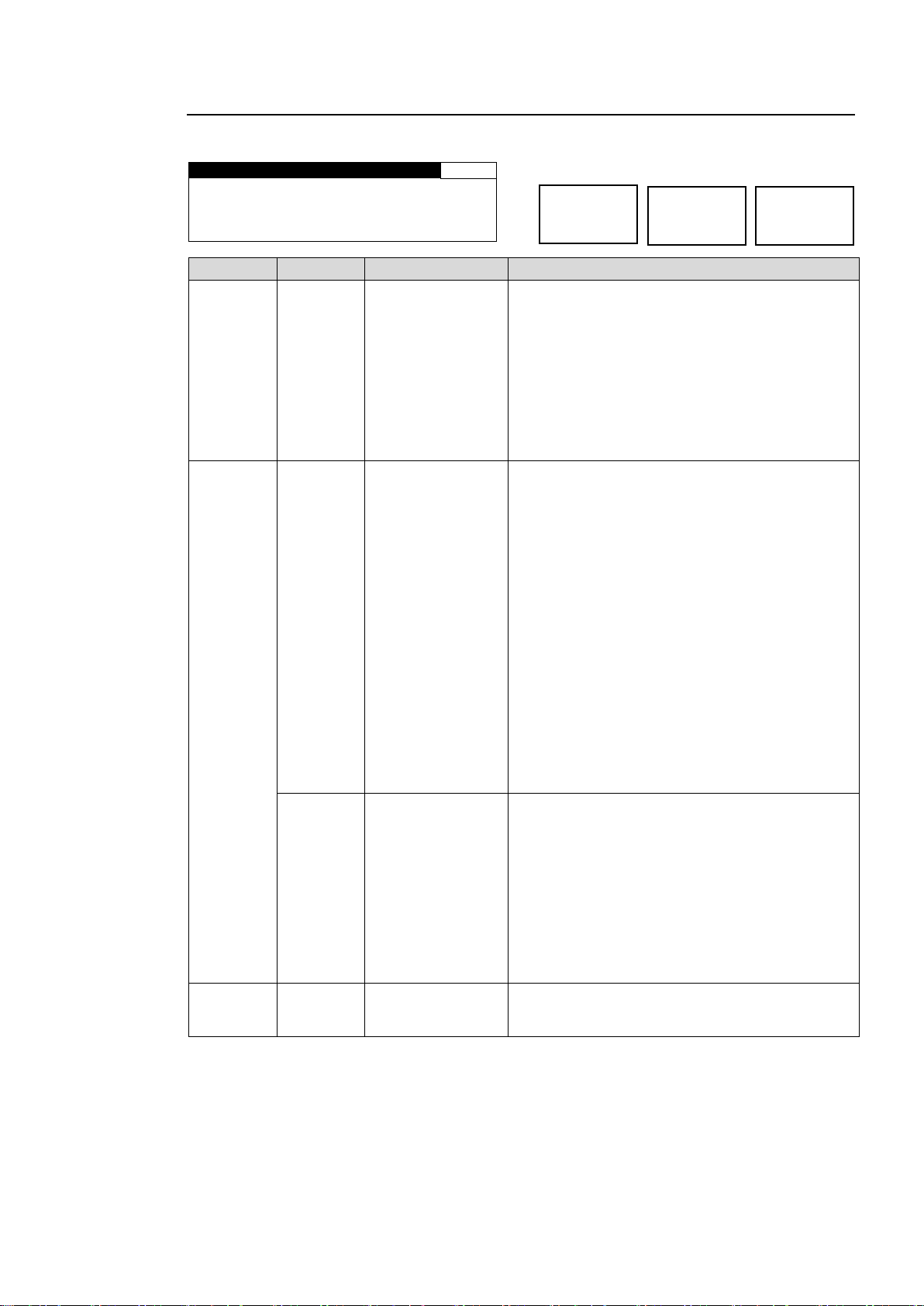
5-3-1. CONV MODE
C O N V M O D E
6
CONV : BY- P A S S
A S P E C T : A F D ( 4 : 3 )
1 0 8 0 / 5 9 i > > 5 2 5 / 6 0
Parameter
Default
Setting range
Description
CONV
BY-PASS
BY-PASS
SD
1080i
720p
1080PsF
1080p(3G)
Selects a mode for UP/DOWN CONVERTER to
convert the input signal in FS1 and FS2.
BY-PASS: Outputs the signal without converting.
SD: Converts signals to a standard definition
format.
1080i: Converts signals to a 1080i format.
720p: Converts signals to a 720p format.
1080PsF: Converts signals to a 1080PsF format.
1080P(3G): Converts signals to a 3G-SDI 1080p
format.
ASPECT
AFD(4:3)
AFD(4:3)
AFD-ALT(4:3)
AFD(16:9)
AFD-ALT(16:9)
4:3 L 16:9 T
4:3 L 14:9 T
4:3 L>16:9
4:3 F 4:3
4:3 L16:9PRTD
4:3 L 14:9
4:3 F ALT14:9
4:3 L ALT14:9 *1
4:3 L ALT 4:3 *1
16:9L >16:9
16:9 F 16:9 *1
16:9 P 4:3
16:9 F PRTD *1
16:9 P 14:9 *1
16:9P ALT 14:9 *1
16:9F ALT14:9 *1
16:9F ALT4:3 *1
Selectable aspect ratio settings when CONV is
set to SD.
AFD(4:3), AFD-ALT(4:3), AFD(16:9),
AFD-ALT(16:9) automatically select an aspect
ratio according to the AFD data in the input signal.
If no AFD data is found in the input signal, the
aspect ratio will be determined according to the
setting made under ANC LOSS SET
(Sec. 5-9-75-9-7).
To output video signals in 4:3, select either ratio
with (4:3). To output in 16:9, select either ratio
with (16:9). Other options will output video signals
in the specified aspect ratio. See section 20
“About AFD (Active Format Description)” for
details.
Options (4:3 L 16:9 T to 16:9 F ALT 4:3) other
than the above four require the input signal
aspect ratio to be specified in VIDEO INPUT SET
(Sec. 5-6-2) if the input signal is an SD signal.
AFD
AFD
AFD-ALT
16:9 L>16:9
16:9 F 16:9
16:9 P 4:3
16:9 F PRTD
16:9 P 14:9
16:9P ALT14:9
16:9F ALT14:9
16:9F ALT4:3
Selectable aspect ratios when CONV is set to
1080i, 720p, 1080PsF, or 1080(3G).
AFD and AFD-ALT automatically select an aspect
ratio according to the AFD data in the input signal.
If no AFD data is found in the input signal, the
aspect ratio will be determined according to the
setting made under ANC LOSS SET (Sec. 5-9-7).
Options other than the above two are output in
the specific aspect ratio. See section 20 “About
AFD (Active Format Description)” for details on
conversions according to AFD data.
- - -
The format of the input signal to CONV and the
format the signal will be converted to in CONV of
FS1 and FS2 are displayed on the 4th row.
*1 BT1119 WSS will be embedded according to the WSS AFD ERROR settings (Sec. 5-9-8) for the
non-WSS aspect ratio conversions.
FS1/LOCK
FS2/LOCK
Menu button
CONV1
ANALOG
Converts video signals according to the AFD (Active Format Description) data.
* Settings can be set for FS1 and FS2 respectively.
41
Page 42
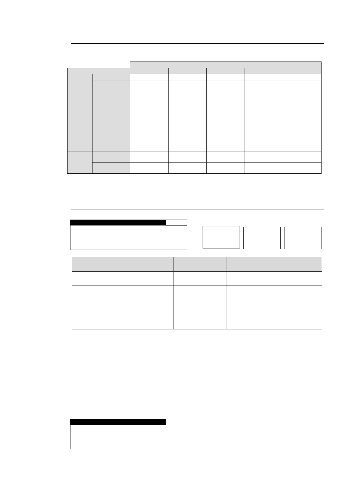
5-3-2. CONV Conversion Table
CONVERTER mode selection
Input signal
SD
1080i
720p
1080PsF
1080p(3G)
NTSC
formats
525/60
525/60
1080/59i
720/59p
1080/23PsF
1080/59p
1080/59i
525/60
1080/59i
720/59p
1080/59i
(BY-PASS)
1080/59p
720/59p
525/60
1080/59i
720/59p
720/59p
(BY-PASS)
1080/59p
1080/59p
525/60
1080/59i
720/59p
1080/59p
(BY-PASS)
1080/59p
PAL
formats
625/50
625/50
1080/50i
720/50p
1080/24PsF
1080/50p
1080/50i
625/50
1080/50i
720/50p
1080/50i
(BY-PASS)
1080/50p
720/50p
625/50
1080/50i
720/50p
720/50p
(BY-PASS)
1080/50p
1080/50p
625/50
1080/50i
720/50p
1080/50p
(BY-PASS)
1080/50p
Other
formats
1080/23PsF
525/60
1080/23PsF
(BY-PASS)
1080/23PsF
(BY-PASS)
1080/23PsF
1080/23PsF
(BY-PASS)
1080/24PsF
625/50
1080/24PsF
(BY-PASS)
1080/24PsF
(BY-PASS)
1080/24PsF
1080/24PsF
(BY-PASS)
In the conversions to the formats indicated as (BY-PASS), the CONV SIZE/POS, CONV CROPPING,
CONV IMPROVE, and CONV SIDE RGB settings cannot be changed.
C O N V S I Z E / P O S
7
H S I Z E : 1 0 0 . 0 %
V S I Z E : 1 0 0 . 0 %
H P O S : 0 P I X E L
V P O S : 0 L I N E
Parameter
Default
Setting range
(Steps)
Description
H SIZE
(Horizontal Size)
100.0%
50.0 - 150.0%
(0.1%)
Adjusts the width of the video
displayed on the monitor. *1
V SIZE
(Vertical Size)
100.0%
50.0 - 150.0%
(0.1%)
Adjusts the height of the video
displayed on the monitor. *1
H POS
(Horizontal Position)
0 Pixel
Variable *2
(2 Pixel)
Adjusts the horizontal position of
the video displayed on the monitor.
V POS
(Vertical Position)
0 Line
Variable *2
(1 Line)
Adjusts the vertical position of the
video displayed on the monitor.
C O N V S I Z E / P O S
7
H S I Z E : N O T A D J U S T
V S I Z E : N O T A D J U S T
H P O S : N O T A D J U S T
V P O S : N O T A D J U S T
FS1/LOCK
FS2/LOCK
Menu button
CONV1
ANALOG
Possible Conversions in CONV for Input Signal Formats and Mode Selections
5-3-3. CONV SIZE/POS
(Common for FS1 and FS2)
* Settings can be set for FS1 and FS2, respectively.
*1 If the size is made smaller than the original size, set the background color under CONV
SIDE RGB (see section 5-3-6).
*2 The following parameters interact with each other. When you change one of their setting
values, setting ranges of other parameters will also change.
SYNC FRMT Parameter in FS MODE SET (see section 5-9-1).
CONV parameter in CONV MODE (see section 5-3-1).
If the CONV mode is set to BY-PASS, the CONV SIZE/POS setting cannot be changed. Also,
it cannot be changed if the conversion is set to the formats indicated as (BY-PASS) in the
CONV Conversion Table (see section 5-3-2). In both cases, the menu as shown below will be
displayed.
42
Page 43
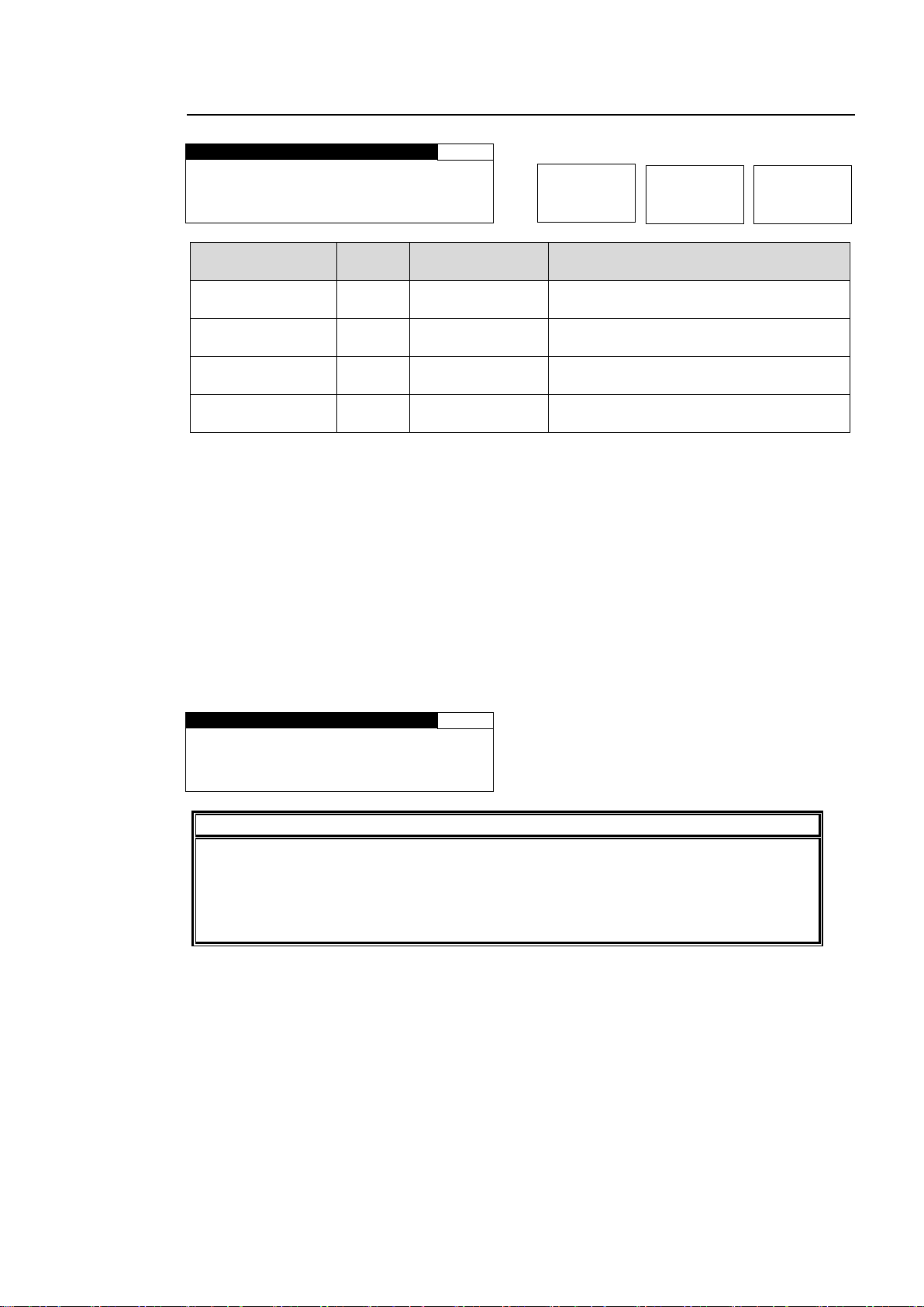
5-3-4. CONV CROPPING
C O N V C R O P P I N G
8
L E F T : 0 P I X E L
R I G H T : 0 P I X E L
T O P : 0 L I N E
B O T T O M : 0 L I N E
Parameter
Default
Setting range
(Steps)
Description
LEFT
0 Pixel
Variable *1
(2 Pixel)
Crops the left side of the video.
RIGHT
0 Pixel
Variable *1
(2 Pixel)
Crops the right side of the video.
TOP
0 Line
Variable *1
(1 Line)
Crops the top of the video.
BOTTOM
0 Line
Variable *1
(1 Line)
Crops the bottom of the video.
C O N V C R O P P I N G
8
L E F T : N O T A D J U S T
R I G H T : N O T A D J U S T
T O P : N O T A D J U S T
B O T T O M : N O T A D J U S T
IMPORTANT
The cropping setting range resets itself if the video input changes. If the set value
exceeds the setting range due to an input change, the set value will automatically
reset itself to the default value. If the set value exceeds the horizontal range, the LEFT
and RIGHT settings will reset to their default values. If the value exceeds the vertical
range, the TOP and BOTTOM settings will also reset accordingly.
FS1/LOCK
FS2/LOCK
Menu button
CONV1
ANALOG
* Settings can be set for FS1 and FS2, respectively.
These setting ranges vary depending on the input signal format. The LEFT and RIGHT
settings, and the TOP and BOTTOM settings interact with each other. If the size cannot be
adjusted as desired, try changing the setting of another parameter.
*1 The following parameters interact with each other. When you change one of their setting
values, setting ranges of other parameters will also change.
Video format
SYNC FRMT Parameter in FS MODE SET (see section 5-9-1).
If the CONV mode is set to BY-PASS, the CONV CROPPING setting cannot be changed. Also,
it cannot be changed if the conversion is set to the formats indicated as (BY-PASS) in the
CONV Conversion Table (see section 5-3-2). In both cases, the menu as shown below will be
displayed.
43
Page 44
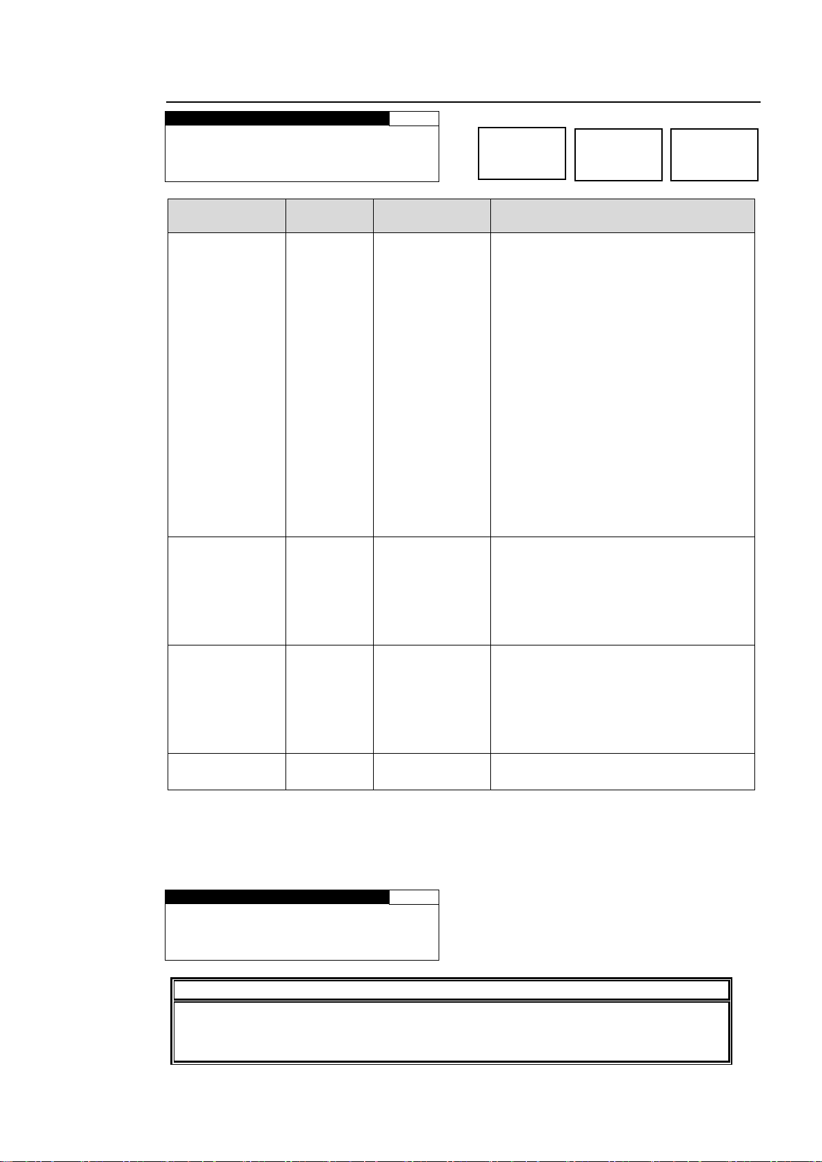
5-3-5. CONV IMPROVE
C O N V I M P R O V E
9
M O T I O N : A D A P T I V E
A N T I A L I A S H : N O R M A L
A N T I A L I A S V : N O R M A L
E N H A N C E : L E V E L 0
Parameter
Default
Setting range
(Steps)
Description
MOTION
ADAPTIVE
FIELD
ADAPTIVE
FRM(ODD 1st)
FRM(EVEN 1st)
FIELD: Generates a progressive scan
image from one field of an interlaced
scan image.
The created image has no motion
artifacts, but vertical resolution will be
reduced.
ADAPTIVE:
Detects whether there is motion or no
motion in the scene, and generate an
optimal progressive scan image.
FRM(ODD 1st):
Generates a progressive scan image
from two fields (odd/even) of and
interlaced scan image.
Suitable for the progressive segment
frame input of progressive scan signals.
FRM(EVEN 1st):
Generates a progressive scan image
from two fields (even/odd) of interlaced
scan image.
ANTIALIAS H *1
NORMAL
WEAK 8-1
NORMAL
STRONG1-8
Performs horizontal anti-aliasing for the
output video image.
WEAK 8 to STRONG 8 (low to high)
This setting cannot be changed if the
conversion is set to the formats indicated
as (BYPASS) in the CONV Conversion
Table in section 5-3-2.
ANTIALIAS V *1
NORMAL
WEAK 8-1
NORMAL
STRONG1-8
Performs vertical anti-aliasing for the
output video image.
WEAK 8 to STRONG 8 (low to high)
This setting cannot be changed if the
conversion is set to the formats indicated
as (BYPASS) in the CONV Conversion
Table in section 5-3-2.
ENHANCE *1
LEVEL 0
LEVEL 0-8
Sharpens the output video image.
LEVEL 0 to 8 (low to high)
C O N V I M P R O V E
9
M O T I O N : F I E L D
A N T I A L I A S H : N O T A D J
A N T I A L I A S V : N O T A D J
E N H A N C E : N O T A D J U S T
IMPORTANT
Setting MOTION to FRM (ODD 1st) or FRM (EVEN 1st) for input signals other than
progressive segment frame inputs causes motion artifacts to appear. In such case,
change the MOTION setting to FIELD or ADAPTIVE.
FS1/LOCK
FS2/LOCK
Menu button
CONV1
ANALOG
* Settings can be set for FS1 and FS2, respectively.
*1 ANTIALIAS and ENHANCE settings cannot be changed if CONV MODE is set to BY-PASS,
or the conversion is set to the formats indicated as (BY-PASS) in the CONV Conversion
Table (see section 5-3-2).
In both cases, the menu as shown below will be displayed.
44
Page 45
5-3-6. CONV SIDE RGB
C O N V S I D E R G B
10
R E D : 0
G R E E N : 0
B L U E : 0
G R O U P A D J U S T
Parameter
Default
Setting range
Description
RED, GREEN, BLUE
(Background color)
0
0 - 255
Sets background color that will be visible if
the converted image is set smaller than
original in CONV SIZE/POS (5-3-3).
R, G, and B components can be adjusted
separately.
F4 control knob allows you to adjust R, G,
and B at the same time.
Group Adjust
(Group Adjustment)
0
0 - 255
Adjusts the R, G, and B components
separately, then turns this Group Adjust
on. Changing any R, G, or B value will
change the values of the three
components accordingly while retaining
the proportion.
C O N V I M P R O V E
10
R E D : N O T A D J U S T
G R E E N : N O T A D J U S T
B L U E : N O T A D J U S T
FS1/LOCK
FS2/LOCK
Menu button
CONV1
ANALOG
* Settings can be set for FS1 and FS2, respectively.
If the CONV mode is set to BY-PASS, the CONV SIDE RGB setting cannot be changed. Also,
it cannot be changed if the conversion is set to the formats indicated as (BY-PASS) in the
CONV Conversion Table (see section 5-3-2). In both cases, the menu as shown below will be
displayed.
45
Page 46
5-4. Auto Video Optimizer (AVO)
A V O S E T T I N G
1 6
M O D E : O F F
L E V E L : S T A N D A R D
A R E A : F U L L S C R E E N
A R E A D I S P L A Y : O F F
Parameter
Default
Setting range
Description
MODE
(Auto level
adjustment)
OFF
OFF
AUTO *1
HOLD *1
AUTO: Enables automatic level adjustment.
HOLD: Stops auto level adjustment. When
MODE selection is changed from AUTO to
HOLD, the signal levels stop and remain as they
are.
OFF: Disables automatic level adjustment.
When MODE selection is changed from AUTO
to OFF, the signal levels return to their state
before auto level adjustment is applied. When
set to OFF, the signal levels can be manually
adjusted. See section 5-4-4-1 “Manual Level
Adjustment” for details.
LEVEL
(Adjustment
level)
STANDARD
DARKER
DARK
STANDARD
BRIGHT
BRIGHTER
USER1,
USER2,
USER3,
USER4,
USER5
Selects a type of signal level adjustment.
10 options are available: Five fixed options and
five custom options.
Darker < Dark < Standard < Bright < Brighter
User1 - User5: Customizable
Selecting one user settings from User1 through
5 opens the USER1 - 5 LEVE SET page. See
section 5-4-3 “USER1 - 5 LEVEL SET” for
details.
AREA
(Sample area)
FULL
SCREEN
FULL
SCREEN,
-
BOTTOM
RIGHT,
USER
AREA1,
USER
AREA2
Sets the sample area to calculate the
adjustment.
10 options are available: Eight fixed areas and
two custom areas.
Fixed areas
FULL SCREEN, LETTER BOX, PILLAR BOX,
CENTER, TOP-LEFT, TOP-RIGHT,
BOTTOM LEFT, BOTTOM RIGHT
(See "Sample Area" in the next page.)
Custom areas
Selecting USER AREA1, or 2 opens the USER
AREA SET page.
See section 5-4-4 “USER1,2 AREA SET” for
details.
AREA
DISPLAY
(Marker
display)
OFF
OFF,
ON
Sets sample area display ON/OFF. If set to ON,
the sample area appears as a semi-transparent
white rectangle on all output videos.
It is set to OFF at startup. Also, if MODE is set to
OFF, AREA DISPLAY is automatically set to
OFF.
*1 MODE cannot be set to AUTO or HOLD when LINK setting mode is enabled in the FA-9520
or a connected FA-95RU. To set to AUTO or HOLD, disable LINK setting mode. See
sec. 4-2-8. “Switching Between 2-Channel Frame Synchronizers” for details on LINK
settings.
IMPORTANT
The Auto Level Adjustment will provide optimal results in many cases, but it does not
always yield optimal results. Sample Area determines the area where the data are
sampled and the level adjustments are applied to whole images.
Menu button
AVO
MAPPING
AVO settings are effective for FS1 video signals.
5-4-1. AVO SETTING
46
Page 47
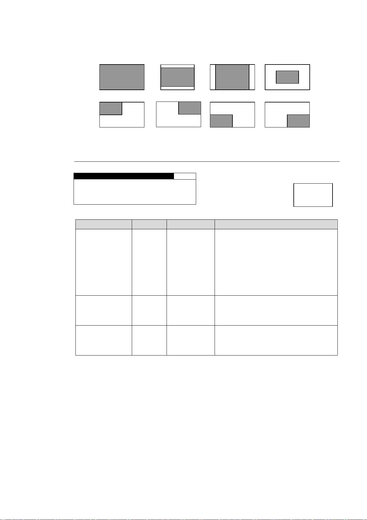
Sample Area (Fixed area)
A V O S E T U P
1 9
R E S P O N S E : L E V E L 3
S C E N E C U T : O F F
G A M M A M O D E : O N
Parameter
Default
Setting range
Description
RESPONSE
(Filtering
strength)
LEVEL 3
LEVEL
1 - 5
Sets the filtering strength for calculating
the mean distances that are applied to
histograms created using the sample
data.
The larger the value, the more gradually
filtering is performed, with a more stable
image but slower response.
The smaller the value, the less stable the
image, but with a faster response.
SCENE CUT *1
(Scene cut
detection)
OFF
OFF,
ON
When set to ON, the cut transitions are
detected and images are properly
adjusted even if there are sharp
luminance changes.
GAMMA MODE
(Gamma
correction)
ON
OFF,
ON
When set to ON, signal levels are
adjusted using the GAMMA LEVEL
settings. (See section 5-2-3 “GAMMA
LEVEL”.
Menu button
AVO
MAPPING
FULL SCREEN
Sample area
LETTER BOX
Sample area
PILLAR BOX
Sample area
CENTER
TOP LEFT
Sample
area
Sample
area
TOP RIGHT
Sample
area
BOTTOM LEFT
Sample
area
BOTTOM RIGHT
Sample
area
Eight available sample areas are as shown below. Data are continuously sampled within each
area. (See section 5-4-4 “USER1, 2 AREA SET” for USERAREA 1, and 2.)
5-4-2. AVO SETUP
*1 The following delay will be produced when performing scene cut detection depending on
the input signal format.
Interlaced formats: 2 fields (1 frame) + some lines
Progressive and PsF formats: 2 frames + some lines
Scene cut detection images will be properly adjusted and output when enough frame delay is
set. If the amount of frame delay is insufficient, Scene cut detection will not be properly
processed.
To perform AVO scene cut detection properly, set enough delay using the FRAME DELAY
function. The output delay varies depending on the SYNCRO MODE, input signal format,
FRAME DELAY setting, and video signal H/V phase difference. FRAME DELAY settings are
described on the next page.
47
Page 48
5-4-2-1. About Scene Cut Detection and Frame Delay Settings
*1
SYNCHRO
*2
Setting Range per Input Video Format
525/60i
625/50i
1080/59i
1080/50i
720/59p/50p
1080/59p,50p
1080/23PsF, 24PsF
FRAME
1 to 8 FRAME
2 to 8 FRAME
LINE/AVDL
Cannot be set
Cannot be set
INPUT
2 to 8 FRAME
3 to 8 FRAME
*1 FS mode settings under SYNCRO in section 5-9-1 “FS MODE SET”
*2 The current input video format can be verified in the VIDEO IN STATUS menu
(Sec. 5-10-2) for each input selected in the FS INPUT SELECT menu (Sec. 5-6-1).
IMPORTANT
Adjust the audio delay as required in the AUDIO DELAY Settings menu (Sec. 6-6) to
account for any additional video signal delay produced by changing FRAME DELAY.
To properly perform AVO scene cut detection and adjustment, the FRAME DELAY must
be set in the setting range according to the menu settings (5-9-1 “FS MODE SET” menu)
as shown in the table below.
FRAME DELAY Setting Range Chart
48
Page 49
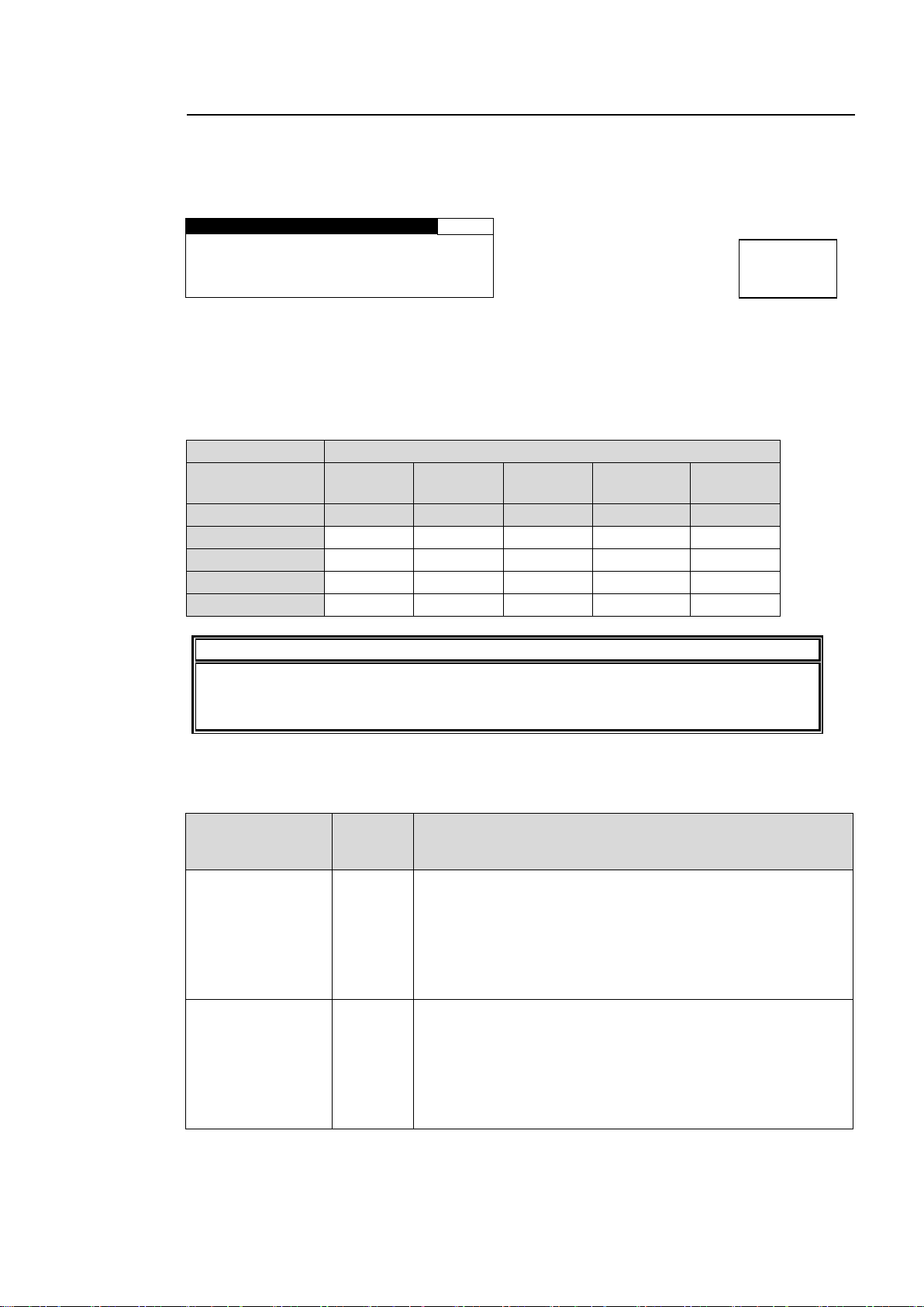
5-4-3. USER1 - 5 LEVEL SET
U S E R 1 L E V E L S E T
1 7
I N W H I T E : 9 9 . 0 %
I N B L A C K : 1 . 0 %
T A R G E T W H I T E : 8 0 . 0 %
T A R G E T B L A C K : 3 . 0 %
Parameter
SELECT LEVEL (Adjustment level)
(Custom levels)
USER1
Default
USER2
Default
USER3
Default
USER4
Default
USER 5
Default
(Fixed levels)
Darker
Dark
Standard
Bright
Brighter
IN WHITE
99.0%
98.0%
97.0%
95.0%
93.0%
IN BLACK
1.0%
2.0%
3.0%
5.0%
7.0%
TARGET WHITE
80.0%
88.0%
93.0%
95.0%
97.0%
TARGET BLACK
3.0%
5.0%
7.0%
12.0%
17.0%
IMPORTANT
While the USER setting menu is open and the LEVEL is changed via web browser or
the connected FA-95RU to other than USERs 1 through 5 in the AVO SETTING menu
(5-4-1), the menu will change to display the AVO SETTING menu (5-4-1).
Parameter
Setting
range
(step)
Description
IN WHITE
80.0% -
99.0%
(0.5%)
The maximum value of luminance in the sample data is
defined as 100%. Based on this reference value, this
determines the highest level of luminance for level control.
If the value is too large, some noise may be picked up and
cause the results to become unstable. If the value is too
small, it increases contrast, but it may cause the images to
be overexposed.
IN BLACK
1.0% -
20.0%
(0.5%)
The minimum value of luminance in the sample data is
defined as 0%. Based on this reference value, this
determines the lowest level of luminance for level control.
If the value is too small, some noise may be picked up and
cause the results to become unstable. If the value is too
large, it increases contrast, but it may cause the images to
be underexposed.
Menu button
AVO
MAPPING
Setting LEVEL of the AVO SETTING menu to one user settings from USER1 through 5 opens
the USER1 - 5 LEVEL SET menu. This menu allows you to store five sets of level settings as
USER1 – 5.
Each USER1 – 5 is composed of four level settings such as IN WHITE, IN BLACK, TARGET
WHITE, and TARGET BLACK. The default settings of USERs 1 through 5 are the same as
those for DARKER, DARK, STANDARD, BRIGHT, and BRIGHTER, respectively. The
desirable level settings are easily obtained by adjusting values from the default values.
USER1 – 5 Default Settings
IN WHITE and IN BLACK
These two parameters determine the highest and lowest levels of luminance in the input
signal.
49
Page 50
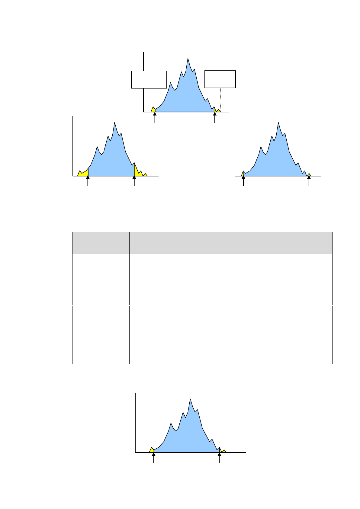
The figures below are luminance histograms of input.
Parameter
Setting
range
(step)
Description
TARGET WHITE
60.0 -
100.0%
(0.5%)
Determines the maximum value of luminance for outputs.
The maximum luminance value of the image after
correction should approximate this value.
The larger the value, the brighter the image, which may
however cause the image to be overexposed. The smaller
the value, tones of the bright part are kept. However, the
overall obtained image may be dark.
TARGET BLACK
0 -
40.0%
(0.5%)
Determines the minimum value of luminance for outputs.
The minimum luminance value of the image after correction
should approximate this value.
The larger the value, the dark area in pictures will appear
brighter, which may however lower the contrast and the
noise will become apparent. The smaller the value, the
higher the contrast, which may however cause the image to
be underexposed.
TARGET BLACK
TARGET WHITE
0%
100%
Reference values
IN BLACK
IN WHITE
Minimum
value of inputs
0%
Maximum
value of
inputs 100%
IN BLACK
IN WHITE
Wide correction range setting
IN BLACK
IN WHITE
Narrow correction range setting
(X-axis: Luminance level, Y-axis: Number of pixels)
TARGET WHITE and TARGET BLACK
These two parameters determine the highest and lowest levels of luminance for target images
(outputs). (See figures below and in the next page.)
The figure below is a luminance histogram of output.
(X-axis: Luminance level, Y-axis: Number of pixels)
50
Page 51
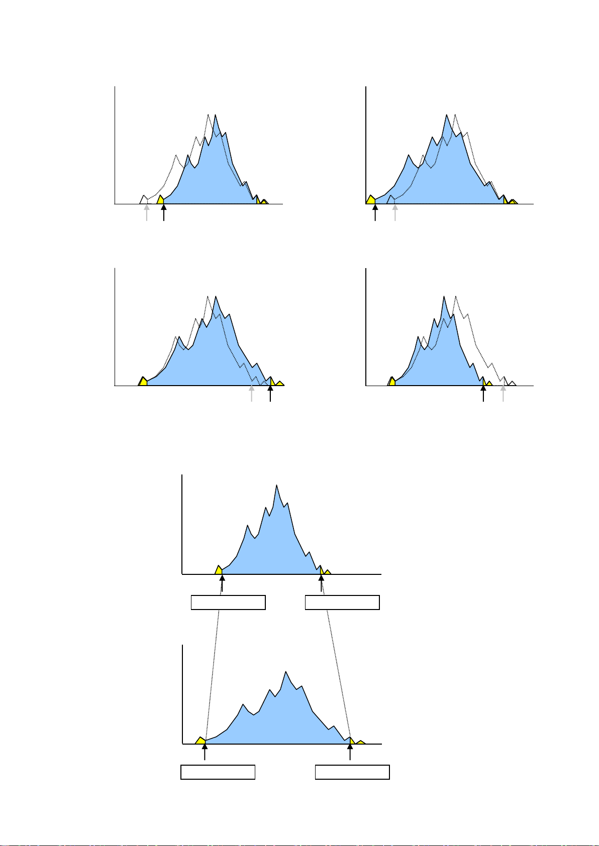
The figures below compare the reference values (dotted line) for output and the actual values
Large TARGET BLACK setting
0%
100%
TARGET BLACK
Small TARGET BLACK setting
0%
100%
TARGET BLACK
Small TARGET WHITE setting
0%
100%
TARGET WHITE
Large TARGET WHITE setting
0%
100%
TARGET WHITE
0%
100%
0%
100%
IN WHITE
IN BLACK
TARGET BLACK
TARGET WHIE
Input image
Output image
after correction (full line).
Relationship between IN BLACK, IN WHITE and TARGET BLACK, TARGET WHITE levels
51
Page 52
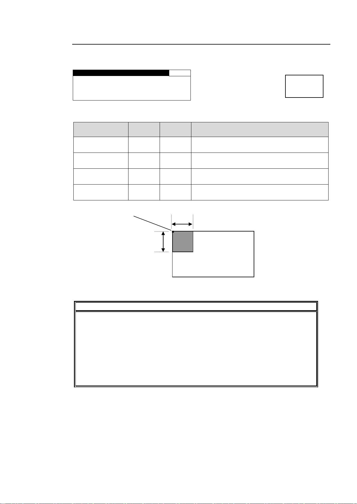
5-4-4. USER1, 2 AREA SET
U S E R 1 A R E A S E T
1 8
S T A R T H : 0 P I X E L
S T A R T V : 0 L I N E
H S I Z E : 3 6 0 P I X E L
V S I Z E : 3 6 0 L I N E
Parameter
Default
Setting
range
Description
START H
0 Pixel
Variable
(2Pixel)
Specifies the horizontal start point.
START V
0 Line
Variable
(2Line)
Specifies the vertical start point.
H SIZE
360
Variable
(2Pixel)
Specifies the horizontal size (distance) from the
start point.
V SIZE
360
Variable
(2Line)
Specifies the vertical size (distance) from the
start point.
IMPORTANT
The sample area should be set within the effective lines and pixels. Otherwise, the
sample area will automatically revert to their default values. Be particularly careful in
the following cases.
- When the video format is changed to SDTV after the sample area has been set.
- When the sample area settings are changed by loading an event.
While the USER 1, 2 AREA SET setting menu is open and the AREA is changed via
web browser or the connected FA-95RU to other than USER AREAs 1 and 2 in the
AVO SETTING menu (5-4-1), the menu will change to display the AVO SETTING
menu (5-4-1).
Sample
area
V SIZE
H SIZE
(START V , START H)
Default setting of sample area
in 1080/59.94i.
Menu button
AVO
MAPPING
Selecting USER1 (or 2) AREA for AREA in the AVO SETTING menu opens the USER1, 2
AREA SET menus.
To set the sample area, set the start point and the size.
52
Page 53
5-4-4-1. Manual Level Adjustment
AVO MODE selection
Color Corrector Menu
Reference
AUTO
HOLD
OFF - ✓
✓
WHITE LEVEL
5-2-1 WHITE LEVEL
- ✓ ✓
BLACK LEVEL
5-2-2 BLACK LEVEL
- ✓ ✓
GAMMA LEVEL
5-2-3 GAMMA LEVEL
- - ✓
CORRECTION MODE /CURVE
5-2-4 COLOR CORRECT
The FA-9520 automatically adjusts the signal level if the MODE of the AVO SETTING
menu is set to AUTO (see section 5-4-1). The signal level can also be manually adjusted if
the MODE is set to HOLD or OFF.
To provide fine adjustment on the automatically adjusted level
Changing the AVO MODE selection from AUTO to HOLD will enable fine adjustment of the
adjusted signal levels that are provided by the automatic level adjustment. However, the
change will not be retained after restarting the unit. The signal levels return to the values
before the manual adjustment (the values provided by the automatic level adjustment).
While AVO is turned on, the COLOR CORRECT menu settings will automatically adjust.
MODE will change to BALANCE, and CURVE to BLACK. The fine adjustment enabled in
HOLD mode is enabled only for color correction BALANCE mode.
To manually adjust the signal levels
Set AVO MODE to OFF to manually adjust the signal levels. If the AVO MODE selection is
changed from AUTO to OFF, the signal levels return to their values before the automatic
level adjustment.
The adjustable items in the Color Correction menus are as shown in the table below.
✓ : The setting is enabled.
- : The setting is disabled.
The message "NOT ADJUST" appears when the disabled menu is opened.
53
Page 54
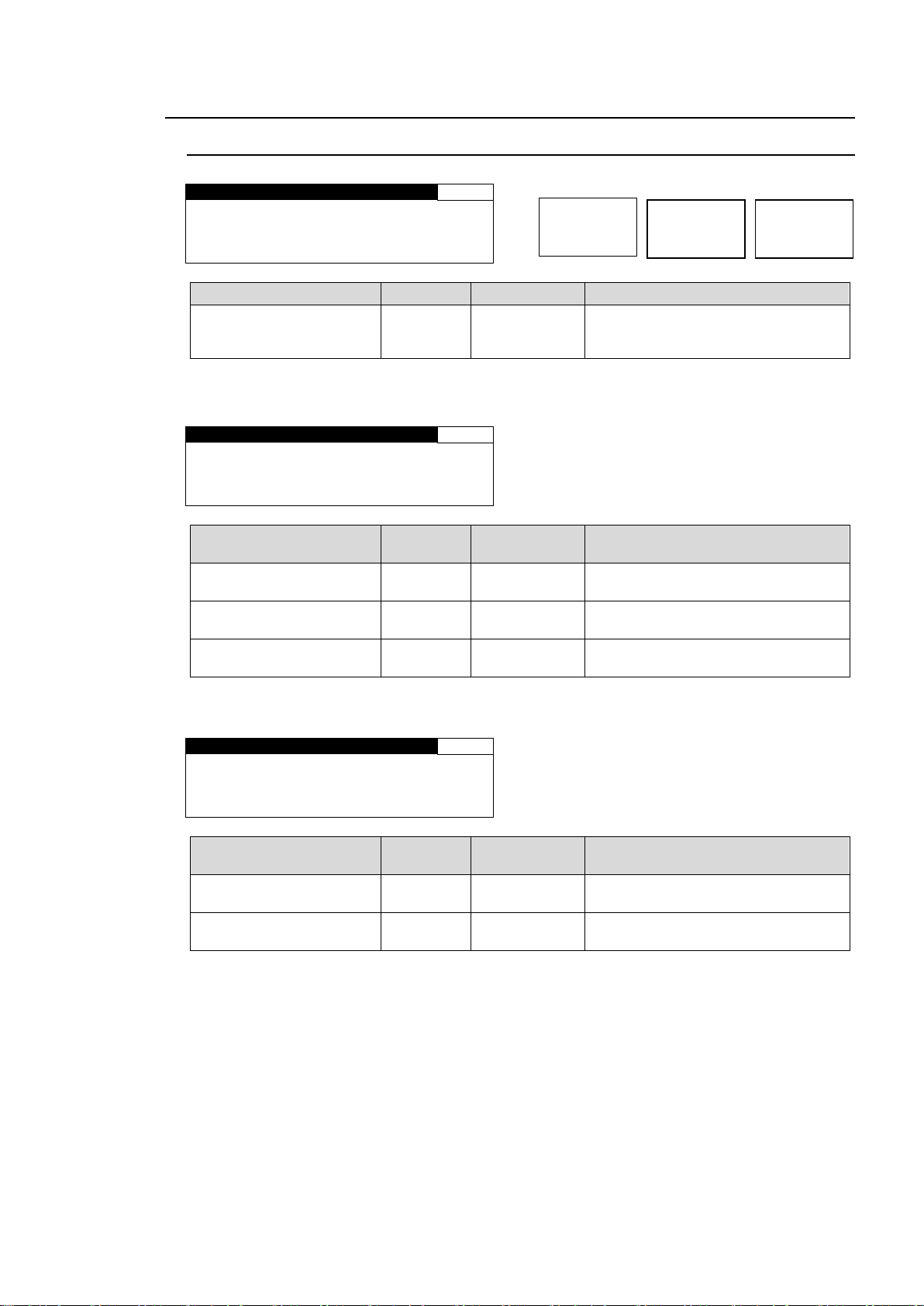
5-5. CLIP (VIDEO CLIP)
Y P b P r / R G B C L I P
2 5
C L I P M O D E : O F F
Parameter
Default
Setting range
Description
CLIP MODE
(Clip Mode)
OFF
OFF,
YPbPr CLIP,
RGB CLIP
Selects a mode whether to clip
signals in the YPbPr color space or
RGB color space.
Y P b P r / R G B C L I P
2 5
M O D E : Y P b P r C L I P
Y W H I T E : 1 0 9 . 0 %
Y B L A C K : - 7 . 5 %
C H R O M A : 1 1 1 . 0 %
Parameter
Default
Setting range
(Steps)
Description
Y WHITE
(Y White Clip)
109.0%
50.0 - 109.0%
(0.5%)
Sets the Y signal upper threshold.
Y BLACK
(Y Black Clip)
-7.5%
-7.5 - 50.0%
(0.5%)
Sets the Y signal lower threshold.
CHROMA
(YPbPr Chroma Clip)
111.0%
50.0 - 111.0%
(0.5%)
Sets both the upper and lower
thresholds of PbPr signals.
Y P b P r / R G B C L I P
2 5
M O D E : R G B C L I P
W H I T E : 3 0 0 . 0 %
BLACK:- 2 0 0 . 0 %
Parameter
Default
Setting range
(Steps)
Description
WHITE
(RGB White Clip)
300.0%
50 - 300%
(0.5%)
Sets the upper threshold of RGB
color space.
BLACK
(RGB Black Clip)
-200.0%
-200 - 50%
(0.5%)
Sets the lower threshold of RGB
color space.
FS1/LOCK
FS2/LOCK
Menu button
CLIP
DELAY
5-5-1. YPbPr/RGB CLIP
* Settings can be set for FS1 and FS2, respectively.
YPbPr CLIP
RGB CLIP
54
Page 55
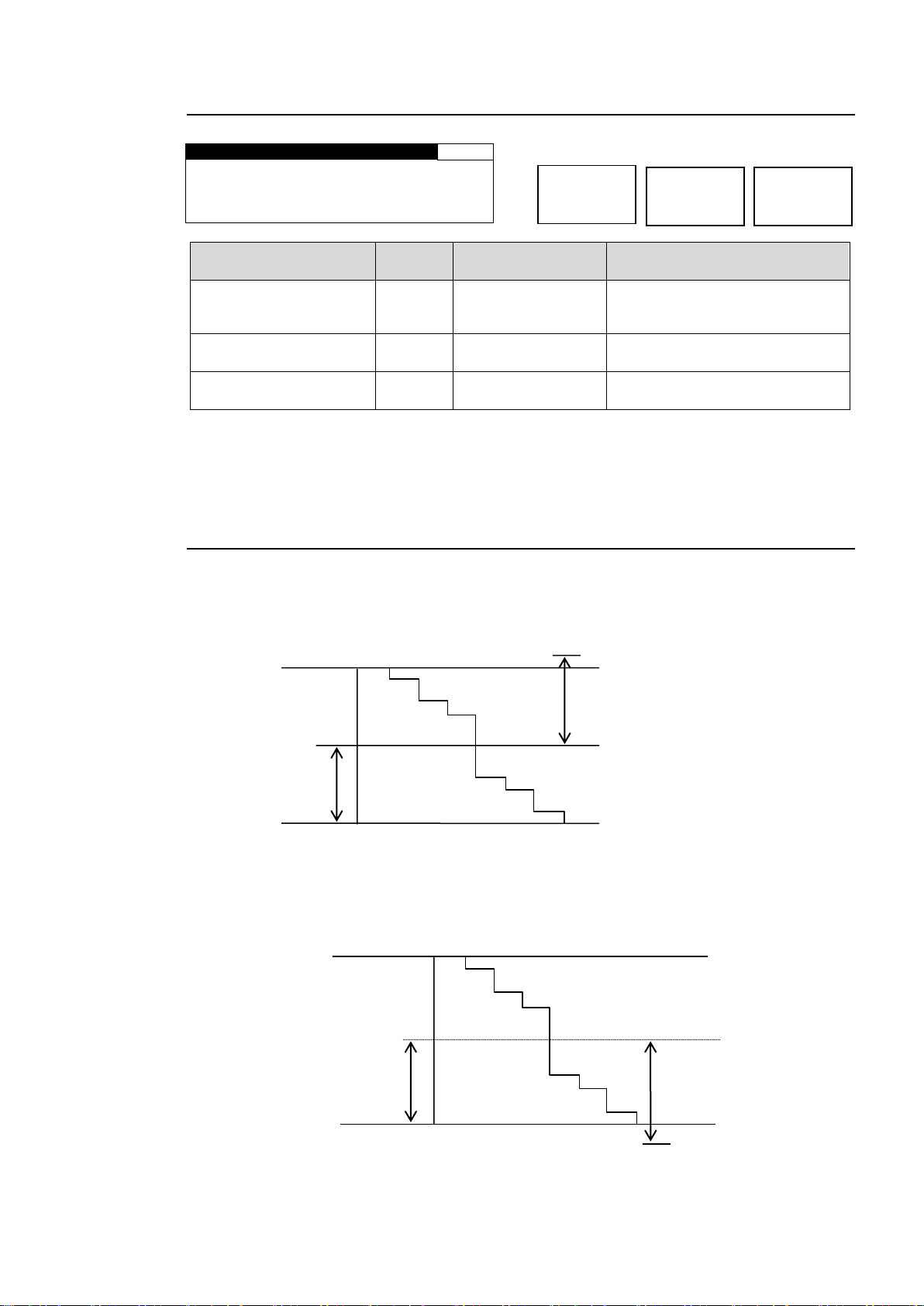
5-5-2. COMPOSITE CLIP
C O M P O S I T E C L I P
2 6
M O D E : C O M P O S I T E C L I P
W H I T E : 1 5 0 . 0 %
BLACK: - 5 0 . 0 %
Parameter
Default
Setting range
(Steps)
Description
CLIP MODE
(Clip Mode)
OFF
OFF,
COMPOSITE CLIP
COMPOSITE CLIP enables
clipping on the composite output
signals.
WHITE
(Composite White Clip)
150.0%
50 - 150%
(0.5%)
Sets the upper threshold of
analog composite color space.
BLACK
(Composite Black Clip)
-50.0%
-50 - 50%
(0.5%)
Sets the lower threshold of
analog composite color space.
SMPTE 100% color bar when 100% white.
109%
100%
50%
50%
0%
Y white clip level setting range
Y Black clip level setting range
SMPTE 100% color bar when 100% black.
100%
50%
0%
50%
-7.5%
FS1/LOCK
FS2/LOCK
Menu button
CLIP
DELAY
The COMPOSITE CLIP settings are effective only on the analog composite outputs.
The settings are not effective on the SDI1/2 and SDI3/4 outputs.
To enable the COMPOSITE CLIP menu, set YPbPr/RGB CLIP to OFF.
5-5-3. VIDEO CLIP Setting Ranges
YPbPr CLIP
Y Signal Settings
① Y White Clip Level
Setting range 50 - 109% (Default: 109%)
② Y Black Clip Level
Setting range -7.5 - 50% (Default: -7.5%)
55
Page 56
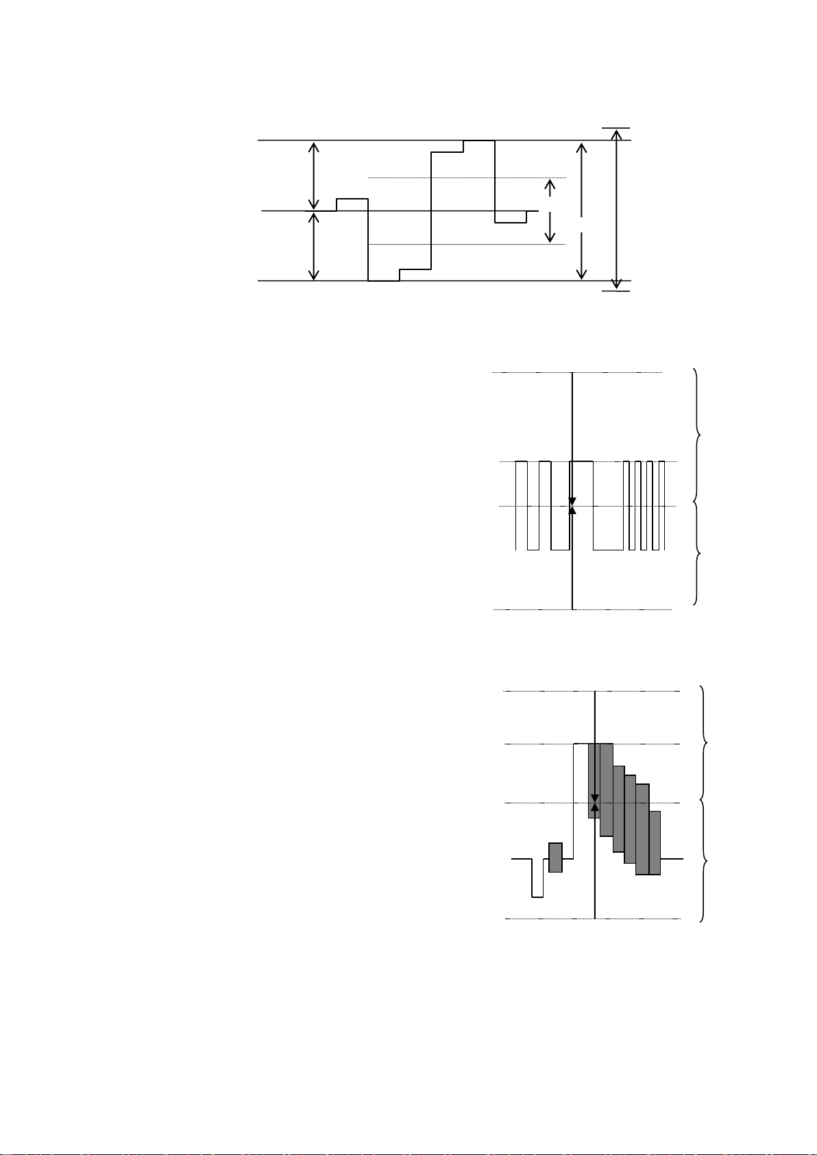
③ C White Clip Level
300%
100%
-200%
0%
50%
White
setting
range
Black
setting
range
RGB Clip Processing
50%
50%
100%
111% (default)
SMPTE 100% color bar when color 700mVp-p.
150%
100%
0%
-50%
50%
White
setting
range
Black
setting
range
Composite Clip processing
Setting range 50 - 111% (Default: 111%)
RGB CLIP
To adjust the RGB clipping, select the RGB
CLIP under CLIP MODE, and then set RGB
White Clip and RGB Black Clip.
Once the “RGB CLIP” is selected, the YPbPr
input video signal is converted into an RGB
signal in the unit. The converted RGB signal
is processed so as not to exceed the RGB
gamut range set under the RGB White Clip
and RGB Black Clip parameters in the
menu.
Then the processed RGB signal is
converted again to YPbPr format. This
correction is used to eliminate out-of RGB
gamut problems.
COMPOSITE CLIP
To adjust the COMPOSITE clip, set WHITE
and BLACK.
Once the COMPOSITE CLIP mode is
turned ON, YPbPr input video signal is
converted to composite signal in the unit.
The converted composite signal is
processed so as not to exceed the
composite gamut range set at WHITE and
BLACK in the menu.
The processed composite signal is then
reconverted to YPbPr format. This
correction is used to eliminate out-of
composite gamut problems.
This correction is applied to composite
output signals.
56
Page 57
5-6. VIDEO INPUT SELECT (IN SEL)
F S I N P U T S E L E C T
28
F S 1 I N S E L : S D I 1
F S 2 I N S E L : S D I 2
Parameter
Default
Setting range
Description
FS1 IN SEL
SDI1
SDI1
SDI2
COMPOSITE
OPTION A *1
OPTION B *2
Selects an input video signal for
FS1.
OPTION A: Input signal from the
FA-95AIO in option slot A.
OPTION B: Input signal from the
FA-95AIO in option slot B.
FS2 IN SEL
SDI2
SDI1
SDI2
COMPOSITE
OPTION A *1
OPTION B *2
Selects an input video signal for
FS2.
OPTION A: Input signal from the
FA-95AIO in option slot A.
OPTION B: Input signal from the
FA-95AIO in option slot B.
Menu button
IN SEL
DOWNMIX
Allows you to select input video signals, and select the operation for when signal input is lost.
5-6-1. FS INPUT SELECT
*1 Selectable only if the FA-95AIO option is installed in option slot A.
*2 Selectable only if the FA-95AIO option is installed in option slot B.
COMPOSITE, OPTION A, or OPTION B cannot be selected for both FS1 and FS2.
If you wish to select COMPOSITE, OPTION A, or OPTION B for either FS while the same
signal is selected for the other FS, reset the current COMPOSITE, OPTION A, or OPTION B
selection to SDI 1 or 2 first, then select a signal as you wish.
If COMPOSITE, OPTION A or OPTION B is selected for both FS1 IN SEL and FS2 IN SEL,
the “CANNOT ASSIGN SIMUL COMPOSITE, FA-95AIO” alert message will appear.
57
Page 58
5-6-2. VIDEO INPUT SET
V I D E O I N P U T S E T
29
L O S S : B A C K C O L O R
B A C K C O L O R : O F F
S D A S P E C T : 4 : 3
I N S T A T U S :
Parameter
Default
Setting range
Description
LOSS
BACK COLOR
BACK COLOR
AUTO FREEZE *1
COLOR BAR
OUT DISABLE
Selects an operation for the time the
signal input selected under FS
INPUT SELECT is lost.
BACK COLOR
BLACK
OFF
BLACK
BLUE
RED
MAGENTA
GREEN
CYAN
YELLOW
Select a background color.
SD ASPECT
4:3
4:3
16:9
Selects the aspect ratio for SD input
signals.
This setting is used for fixed aspect
ratio conversions that are performed
when ASPECT in the CONV menu is
set to other than AFD (4:3),
AFD-ALT (4:3), AFD (16:9),
AFD-ALT (16:9), AFD, or AFD-ALT.
IN STATUS
-
SDI1
SDI2
OPTION A
OPTION B
Displays the input video signal in
FS1 or FS2. (Cannot be changed.)
FS1/LOCK
FS2/LOCK
Menu button
IN SEL
DOWNMIX
* Settings can be set for FS1 and FS2, respectively.
*1 The selected AUTO FREEZE functions the same as BACK COLOR if SYNCHRO in
section 5-9-1 “FS MODE SET” is set to LINE or AVDL. In such case, the menu is indicated
as “*AUTO FREEZE”.
LOSS Operation
If the signal input that is selected under FS INPUT SELECT is lost, the FA-9520 operates in
the selected LOSS mode as follows.
In BACK COLOR mode
Outputs a matte signal of the color selected under BACK COLOR.
In AUTO FREEZE mode
Freezes the last image before signal input is lost.
Freezes the field.
Freezes the frame if the lost input signal is of a progressive scan video format such as
720p.
In COLOR BAR mode
Outputs the SMPTE color bar.
In OUT DISABLE mode
Does not output any signal from SDI OUT1, 2, 3, 4, COMPOSITE OUT1 or 2.
In AUTO FREEZE mode
Outputs a black screen if SYNCHRO is set to LINE or AVDL under FS MODE SET
(section 5-9-1).
58
Page 59
5-6-3. ANC DETECT LINE
A N C D E T E C T L I N E
30
ANC : R P 1 8 6 V I
FORMAT: 525/60
FIELD1: 1 4 L I N E
FIELD2: 2 7 7 L I N E
Parameter
Default
Setting range
Description
ANC
RP186 VI
RP186 VI
BT1119 WSS
Selects an ancillary data
standard.
FORMAT
525/60
525/60
625/50
Selects the input signal format.
FIELD1
14 LINE (525/60)
19 LINE (625/50)
12-19 LINE (525/60)
8-22 LINE (625/50)
Selects a line to detect ancillary
data in field 1.
FIELD2
277 LINE (525/60)
324 LINE (625/50)
275-282 LINE (525/60)
321-335 LINE (625/50)
Selects a line to detect ancillary
data in field 2.
A N C D E T E C T L I N E
30
ANC : B T 1 1 1 9 W S S
FORMAT: 625/50
FIELD1: 2 3 L I N E
Parameter
Default
Setting range
Description
ANC
RP186 VI
RP186 VI
BT1119 WSS
Selects an ancillary data
standard.
FORMAT
625/60
625/50
Selects the input video format.
FIELD1
23LINE
8-23 LINE
Selects a line to detect ancillary
data in field 1.
A N C D E T E C T S E L
31
C A P T I O N : C E A 6 0 8 C C
A F D : S 2 0 1 6 - 3AFD
Parameter
Default
Setting range
Description
CAPTION *1
CEA608 CC
CEA608 CC
S334-1 CC
Select CEA608 CC to process closed
caption data in the luminance signal (Y) of
525/60 system.
Select S334-1 CC to process closed
caption data in ancillary data space of SDI
signal.
AFD
S2016-3 AFD
S2016-3 AFD
RP186 VI
BT1119 WSS
Selects a type of AFD data to be detected
for SD input signals.
FS1/LOCK
FS2/LOCK
Menu button
IN SEL
DOWNMIX
FS1/LOCK
FS2/LOCK
Menu button
IN SEL
DOWNMIX
FS1/LOCK
FS2/LOCK
Menu button
IN SEL
DOWNMIX
Allows you to select a line to detect ancillary RP186 VI or BT1119-2 WSS data in input signals.
For RP186 VI
For BT1119 WSS
5-6-4. ANC DETECT SEL
*1 Be sure to set to CEA608 CC when processing closed caption data in 525/60 composite
signals. Otherwise the caption data will not be detected.
59
Page 60
5-6-5. AIO A IN MODE
A I O A I N M O D E
32
M O D E : Y P b P r S M P T E
Parameter
Default
Setting range
Description
MODE
YPbPr SMPTE
YPbPr SMPTE
YPbPr BETACAM
RGB
Y/C
Selects the operation mode for
input video signals in the
FA-95AIO installed in slot A.
This menu will not appear if no
FA-95AIO is installed in slot A.
A I O B I N M O D E
33
M O D E : Y P b P r S M P T E
Parameter
Default
Setting range
Description
MODE
YPbPr SMPTE
YPbPr SMPTE
YPbPr BETACAM
RGB
Y/C
Selects the operation mode for
input video signals in the
FA-95AIO installed in slot B.
This menu will not appear if no
FA-95AIO is installed in slot B.
Menu button
IN SEL
DOWNMIX
Menu button
IN SEL
DOWNMIX
5-6-6. AIO B IN MODE
60
Page 61
5-7. VIDEO OUT SELECT (OUT SEL)
O U T P U T A S S I GN
34
S D I 1 / 2 : F S 1
S D I 3 / 4 : F S 2
C O M P O S I T E : F S 1
Parameter
Default
Setting range
Description
SDI1/2
FS1
FS1
FS2
Selects either FS1 or FS2 signal to be
output from SDI1 and 2 connectors.
SDI3/4
FS1
FS1
FS2
Selects either FS1 or FS2 signal to be
output from SDI3 and 4 connectors.
COMPOSITE
FS1
FS1
FS2
Selects either FS1 or FS2 signal to be
output from COMPOSITE connectors.
Outputs a black signal for HD output
signals.
FS1 and 2 output signals
Output signal from COMPOSITE connector
525/60
CONV signals in 525/60
625/50
CONV signals in 625/50
1080/59i
B.B. in 525/60
1080/50i
B.B. in 625/50
1080/24PsF
B.B. in 625/50
1080/23.98PsF
B.B. in 525/60
720/59p
B.B. in 525/60
720/50p
B.B. in 625/50
1080/59p
B.B. in 525/60
1080/50p
B.B. in 625/50
Menu button
OUT SEL
MODE
Allows you to select output modes and whether to output a signal from FS1 or FS2 for respective
video output connectors.
5-7-1. OUTPUT ASSIGN
Allows you to assign video signals to output from video output connectors.
Composite Output Format Table
61
Page 62
5-7-2. AIO A ASSIGN
A I O A A S S I G N
35
A S S I G N : F S 1
M O D E : Y P b P r S M P T E
Parameter
Default
Setting range
Description
ASSIGN
FS1
FS1
FS2
Selects either FS1 or FS2 signal to
be output from the video output
connector on the FA-95AIO in slot
A.
MODE
YPbPr SMPTE
YPbPr SMPTE
YPbPr BETACAM
RGB
Y/C
Selects the operation mode for
output video signals from the
FA-95AIO installed in slot A.
FS1 or 2 output signal
FA-95AIO YPbPr/RGB
output signal
525/60
525/60 signal in FS 1 or 2
625/50
625/50 signal in FS 1 or 2
1080/59i
1080/59i signal in FS 1 or 2
1080/50i
1080/50i signal in FS 1 or 2
1080/24PsF
1080/24PsF signal in FS 1 or 2
1080/23.98PsF
1080/23.98PsF signal in FS 1 or 2
720/59p
720/59p signal in FS 1 or 2
720/50p
720/50p signal in FS 1 or 2
1080/59p
1080/59i black video
1080/50p
1080/50i black video
FS 1 or 2 output signal
Y/C output signal
525/60
525/60 signal in FS 1 or 2
625/50
625/50 signal in FS 1 or 2
1080/59i
525/60 BB signal
1080/50i
625/50 BB signal
1080/24PsF
625/50 BB signal
1080/23.98PsF
525/60 BB signal
720/59p
525/60 BB signal
720/50p
625/50 BB signal
1080/59p
525/60 BB signal
1080/50p
625/50 BB signal
Menu button
IN SEL
DOWNMIX
Allows you to assign video signals to output from video output connectors on the FA-95AIO in
slot A.
* This menu does not appear if there is no FA-95AIO installed in slot A.
* The FA-95AIO connector outputs a black video if the output signal from the selected FS1
or FS2 is 1080p and MODE is set to YPbPr or RGB. See the below YPbPr/RGB Output
Format table for details.
* The FA-95AIO connector outputs a black video if the output signal from the selected FS1
or FS2 is an HD signal and MODE is set to Y/C. See the below Y/C Output Format table for
details.
YPbPr/RGB Output Format
Y/C Output format
62
Page 63
5-7-3. AIO B ASSIGN
A I O B A S S I G N
35
A S S I G N : F S 1
M O D E : Y P b P r S M P T E
Parameter
Default
Setting range
Description
ASSIGN
FS1
FS1
FS2
Selects either FS1 or FS2 signal to
be output from the video output
connector on the FA-95AIO in slot
B.
MODE
YPbPr SMPTE
YPbPr SMPTE
YPbPr BETACAM
RGB
Y/C
Selects the operation mode for
output video signals from the
FA-95AIO installed in slot B.
FS1 or 2 output signal
FA-95AIO YPbPr/RGB
output signal
525/60
525/60 signal in FS 1 or 2
625/50
625/50 signal in FS 1 or 2
1080/59i
1080/59i signal in FS 1 or 2
1080/50i
1080/50i signal in FS 1 or 2
1080/24PsF
1080/24PsF signal in FS 1 or 2
1080/23.98PsF
1080/23.98PsF signal in FS 1 or 2
720/59p
720/59p signal in FS 1 or 2
720/50p
720/50p signal in FS 1 or 2
1080/59p
1080/59i black video
1080/50p
1080/50i black video
FS 1 or 2 output signal
Y/C output signal
525/60
525/60 signal in FS 1 or 2
625/50
625/50 signal in FS 1 or 2
1080/59i
525/60 BB signal
1080/50i
625/50 BB signal
1080/24PsF
625/50 BB signal
1080/23.98PsF
525/60 BB signal
720/59p
525/60 BB signal
720/50p
625/50 BB signal
1080/59p
525/60 BB signal
1080/50p
625/50 BB signal
Menu button
IN SEL
DOWNMIX
Allows you to assign video signals to output from video output connectors on the FA-95AIO in
slot B.
* This menu does not appear if there is no FA-95AIO installed in slot B.
* The FA-95AIO connector outputs a black video if the output signal from the selected FS1
or FS2 is 1080p and MODE is set to YPbPr or RGB. See the below YPbPr/RGB Output
Format table for details.
* The FA-95AIO connector outputs a black video if the output signal from the selected FS1
or FS2 is an HD signal and MODE is set to Y/C. See the below Y/C Output Format table for
details.
YPbPr/RGB Output Format
Y/C Output format
63
Page 64
5-7-4. ANC DATA EMBED
A N C D A T A E M B E D
37
ANC:C E A 6 0 8 C C
F O R M A T : 5 2 5 / 6 0
E M B E D : D I S A B L E
Parameter
Default
Setting range
Description
ANC
CEA608 CC
CEA608 CC
S334-1 CC SD
CEA708 CC HD
S2016-3 AFD
RP186 VI
BT1119 WSS
Selects an ancillary data type to insert.
FORMAT - *
Selects a video format that supports the
ancillary data selected under ANC. Only
selectable format will be shown.
EMBED
DISABLE
DISABLE
ENABLE
DISABLE: Does not insert ancillary data
selected under ANC.
ENABLE: Inserts ancillary data selected
under ANC.
Data type
Description
CEA608 CC
Closed caption data inserted as Y signals into line 21 of 525/60 analog and SDI
signals.
S334-1 CC
Closed caption data inserted as data packets into the ancillary data space of
525/60 SDI signals.
CEA708 CC
Closed caption data inserted as data packets into the ancillary data space of
HD-SDI signals (1080i/720p).
S2016-3 AFD
Aspect ratio data inserted as data packets into the ancillary data space of SD
and HD-SDI signals (525/60, 625/50, 1080i/PsF, 720p, 1080p/(3G)).
RP186 VI
Aspect ratio data inserted into bit 3 of Chroma data in the SD-SDI (525/60,
625/50) V ANC data space.
BT1119 WSS
Aspect ratio data inserted as Y signals into line 23 of 625/50 analog or SDI
signals.
Menu button
VIDEO SYS
AUDIO SYS
Allows you to set ancillary data insertion into SDI signal ancillary spaces.
* Settings can be set for FS1 and FS2, respectively. See the “Ancillary Data Types” table
below for details.
Ancillary Data Types
64
Page 65
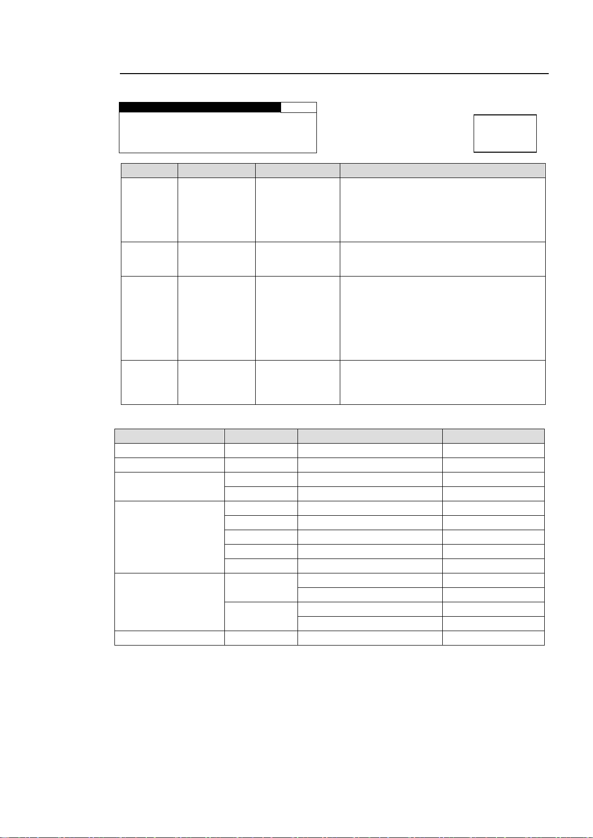
5-7-5. ANC EMBED LINE
A N C E M B E D L I NE
38
A N C : C E A 6 0 8 C C
F O R M A T : 5 2 5 / 6 0
F I E L D 1 : 2 1 ( 2 8 4 ) L I N E
Parameter
Default
Setting range
Description
ANC
CEA608 CC
CEA608 CC
S334-1 CC SD
CEA708 CC HD
S2016-3 AFD
RP186 VI
BT1119 WSS
Selects a type of ancillary data to insert.
FORMAT
-
*1
Selects a video format compatible with the
ancillary data selected under ANC. Only
compatible Video formats will be displayed.
LINE
FIELD1
-
*1
Selects a line in ancillary data space into
which ancillary data is inserted. A line can be
selected for different ANC and FORMAT
selections separately.
If ANC is set to RP186 VI, this parameter
allows you to select a line for FIELD 1. Lines
can be selected for fields 1 and 2
respectively.
FIELD2
-
*1
If ANC is set to RP186 VI, this parameter
allows you to select a line for FIELD 2. Lines
can be selected for fields 1 and 2
respectively.
Ancillary data type
FORMAT
LINE
Default
ANC:CEA 608 CC
525/60
FIELD1: 21(284) fixed *1
ANC:S334-1 CC SD
525/60
FIELD1:12(275) to 19(282) *1
FIELD1:12(275) *1
ANC:CEA708 CC HD
1080i
LINE 9 to 20
LINE 9
720p
LINE 9 to 25
LINE 9
ANC:S2016-3 AFD
525/60
FIELD1:12(275) to 19(282) *1
FIELD1:12(275) *1
625/50
FIELD1:8(321) to 22(335) *1
FIELD1:8(321) *1
1080i/PsF
LINE 9 to 20
LINE 9
720p
LINE 9 to 25
LINE 9
1080p/(3G)
LINE 9 to 41
LINE 9
ANC:RP186 VI
525/60
FIELD1: 12 to 19
FIELD1: 14
FIELD2: 275 to 282
FIELD2: 277
625/50
FIELD1: 8 to 22
FIELD1: 11
FIELD2: 321 to 335
FIELD2: 324
ANC:BT1119 WSS
625/50
FIELD1: 8 to 23
FIELD1: 23
If CEA608 or S334-1 CC closed caption data is detected in the input signal, and
the FS1 and/or FS2 converter output signal format(s) is/are 1080/59i or
720/59p, the detected closed caption data will be automatically converted to
CEA708. However, if CEA708 closed caption insertion is disabled, the data will
not be inserted.
If FS1 and/or FS2 converter output format(s) is/are 1080/PsF or 1080/59p, the
CEA708 closed caption data insertion will be automatically terminated.
Menu button
VIDEO SYS
AUDIO SYS
Allows you to select a line of SDI signal ancillary data space to insert closed caption data.
* Settings can be set for FS1 and FS2, respectively.
*1 The setting range varies according to the ancillary data type and video format.
*1 Field2 line number displayed in parentheses.
65
Page 66
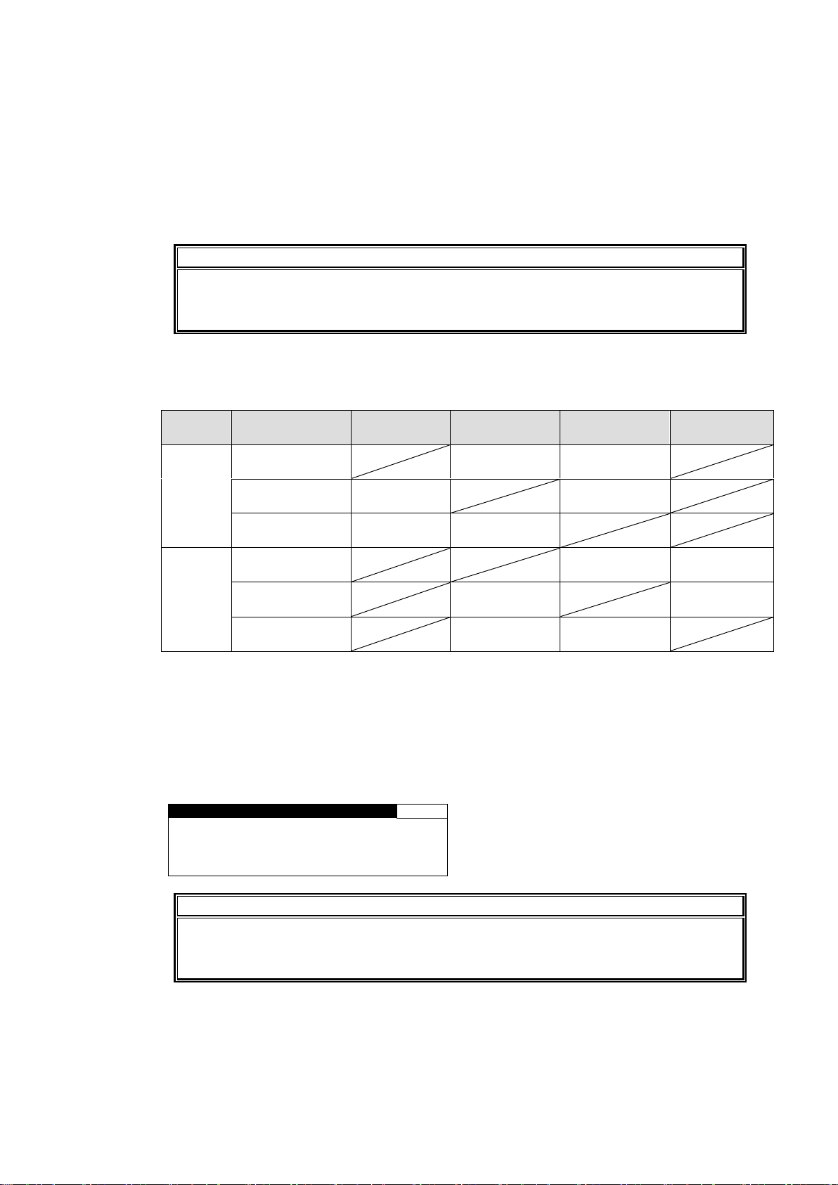
Meanwhile, if CEA708 closed caption data is detected in the 1080/59i or
720/59p HD-SDI input signal, and the FS1 and/or FS2 converter output signal
format(s) is/are 525/60, the detected closed caption data will be automatically
converted to S334-1 CC and/or CEA608 CC.
However, if S334-1 CC and/or CEA608 closed caption insertions are disabled,
the data will not be inserted. If the input signal is 1080/59p or 1080/PsF,
detection and automatic conversion to S334-1 CC and/or CEA608 CC will not
be performed.
IMPORTANT
Closed caption data output will stop when data input is lost. S2016-3 AFD, RP186 VI,
and BT1119 WSS ancillary data will be output according to the ANC LOSS SET
settings when their data input is lost. See section 5-9-7 “ANC LOSS SET” for details.
Video
format
Ancillary data type
S334-1 CC
S2016-3 AFD
RP186 VI
BT1119 WSS
525/60
S334-1 CC
Can be set to
same line
Unable to set
to same line
S2016-3 AFD
Can be set to
same line
Unable to set
to same line
RP186 VI
Unable to set
to same line
Unable to set
to same line
625/50
S2016-3 AFD
Unable to set
to same line
Unable to set
to same line
RP186 VI
Unable to set
to same line
Can be set to
same line
BT1119 WSS
Unable to set
to same line
Can be set to
same line
A N C E M B E D L I N E
38
A N C : * R P 1 8 6 VI
F O R M A T : 5 2 5 / 6 0
F I E L D 1 : * 1 2 L I N E
F I E L D 2 : * 2 7 5 L I N E
IMPORTANT
Ancillary data insersion line settings specified under the ANC DATA EMBED (sec.
5-7-4) and ANC EMBED LINE (sec. 5-7-5) menus take priority over the line settings
specified under the SDI LINE MASK menu (sec. 5-9-13) and take effect.
Ancillary data combinations that cannot be simultaneously embedded to the same
line.
If the same line is set for the ancillary data combination described as “Unable to set to same
line”, and both ancillary data types are set to be embedded in the ANC DATA EMBED menu
(see Sec. 5-7-4), an asterisk “*” will appear next to the selected data type as an error message.
If the sign is displayed, ancillary data will not be properly embedded. The line settings must be
properly set. Usually the default value will properly embed the ancillary data. Keep this in mind
when changing the value to configure a system with other devices.
Error message example:
66
Page 67
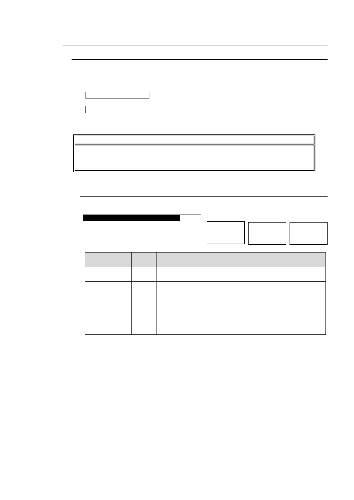
5-8. VIDEO OPTION (VIDEO OP)
IMPORTANT
The FA-9520 front panel button/control operation, and web browser will be slowed
down while storing logo data using FA-95LG GUI. Complete necessary settings before
storing logo data.
L O G O S E L ECT
4 1
L O G O I D : 1
NAME:F O R A
L O G O F O R M A T : H D 1 0 8 0
FS F O R M A T : 1 0 8 0 / 5 9 i
Parameter
Default
Setting
range
Description
LOGO ID
1
1-256
Selects a logo to be output to FS1 or FS2 output
signal.
NAME *1
-
-
Displays the registered name of the ID-selected logo.
Displays “-----“ if the logo is not registered.
LOGO
FORMAT *1
-
-
Displays the format of the ID-selected logo.
Logo formats: SD 525, SD 625, HD 1080, HD 720
Displays “-----“ if the logo is not registered.
FS FORMAT *2
-
-
Displays the video format of the FS1 or FS2 output
signal.
FS1/LOCK
FS2/LOCK
Menu button
VIDEO OP
AUDIO OP
5-8-1. Logo Generator
The logo generator allows you to superimpose logos to FA-9520 outputs for each converter.
Run the FA-95 LG GUI, which can be downloaded from FOR-A’s website, on a PC to register
logos to the FA-9520 via Ethernet. See the FA-95LG GUI Operation Manual (downloaded with
the software) for details on logo management.
The VIDEO OP/AUDIO OP button LED flashes red while storing logo data to the FA-9520
from the FA-95LG GUI. Once the data is stored, it will be transmitted to the video memory.
The VIDEO OP/AUDIO OP button LED flashes green during this transmission. Do not turn
the power of the unit off while the button is flashing in order not to obstruct the data storage
process.
5-8-1-1. LOGO SELECT
Allows you to select a logo function mode for FS1 and FS2.
*1 NAME and LOGO FORMAT can be registered for each logo ID via FA-95LG GUI. See
the separate FA-95LG GUI Operation Manual for details.
*2 The video format displayed under FS FORMAT and the logo format displayed under
LOGO FORMAT must match. Otherwise no logo will be displayed even if KEYER in
section 5-8-1-2 “KEYER SET” is turned On.
67
Page 68
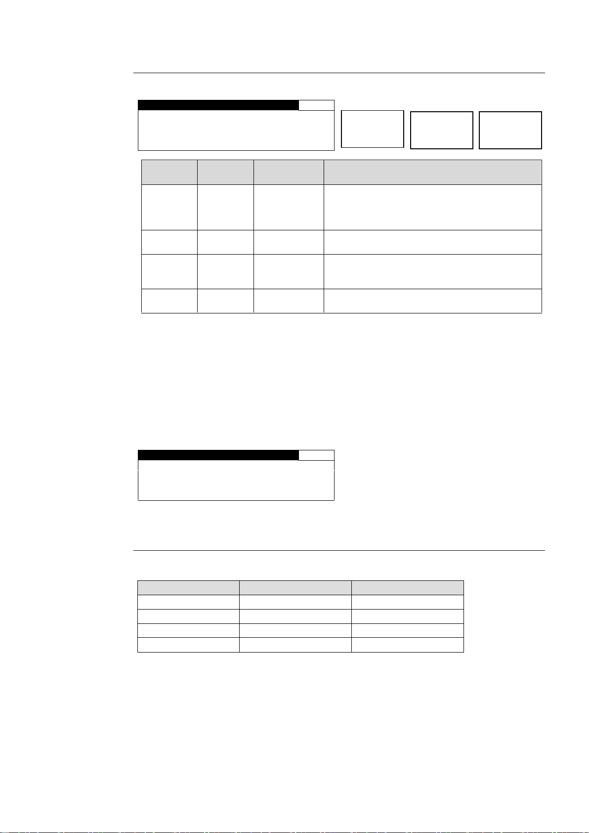
5-8-1-2. KEYER SET
K E Y E R S E T
42
K E Y E R : O F F
LEVEL : 1 0 0 %
H P O S : 0 P I X E L
V P O S : 0 L I N E
Parameter
Default
Setting range
(Steps)
Description
KEYER
OFF
OFF
ON
Allows you to enable or disable the keyer for the
FS1 or FS2 output signal.
ON: Enables display of logos selected in the
LOGO SELECT menu (5-8-1-1).
LEVEL *1
100%
0-100%
(0.1%)
Allows you to set a key level for a logo to be
output to the FS1 or FS2 output signal.
H POS *1
0
*2
(2 Pixel)
Allows you to set the horizontal positon for a
logo to be output to the FS1 or FS2 output
signal.
V POS
*1
0
*2
(1 Line)
Allows you to set the vertical positon for a logo
to be output to the FS1 or FS2 output signal.
K E Y E R S E T
42
K E Y E R : O N
L E V E L : N O T A D J
H P O S : N O T A D J
V P O S : N O T A D J
Logo Format
H POS setting range
V POS setting range
SD 525
0 to 718
0 to 486
SD 625
0 to 718
0 to 575
HD 1080
0 to 1918
0 to 1079
HD 720
0 to 1278
0 to 719
FS1/LOCK
FS2/LOCK
Menu button
VIDEO OP
AUDIO OP
*1 Key level and position settings are saved for each logo ID. Changing logo settings for
FS1 will also change the logo settings of FS2 using the same logo.
*2 Actual logo position differs depending on the logo format selected when registering the
logo. See section 5-8-1-3 “Logo Position Setting Range” for details.
Allows you to set a keyer for FS1 or FS2.
LEVEL and H/V POS settings are disabled under the following conditions:
No logo is assigned to the logo ID selected under LOGO ID in the 5-8-1-1 LOGO
SELECT menu.
Different formats are displayed for LOGO FORMAT and FS1 or FS2 in the 5-8-1-1
LOGO SELECT menu.
5-8-1-3. Logo Position Setting Range
Positional settings will vary according to the logo formats as shown below.
The logo format selection is saved for each logo ID using FA-95LG GUI. See the separate
FA-95LG GUI Operation Manual for details.
68
Page 69
5-9. VIDEO SYSTEM (VIDEO SYS)
F S M O D E S E T
6 1
S Y N C H R O : F R A M E
SYNC F R M T : A U T O D E T
F R A M E D E L A Y : O F F
F O R C E D F I E L D : O F F
Parameter
Default
Setting range
Description
SYNCHRO
*1
*2
*3
*4
*5
FRAME
FRAME
LINE
AVDL*6
FRAME: Enables horizontal and vertical alignment of
video signals to a genlock signal. Effective on both
synchronous and asynchronous signals.
LINE: Locks the video signal of within ±1/2H to a
genlock signal. Output delay is 1H. Effective only when
video signal is synchronous to the genlock signal.
AVDL: Locks the video signal to a genlock signal with a
1H delay. Effective only when video signal is
synchronous to the genlock signal.
INPUT: Locks the system to an input video signal. The
delay can be adjusted by System Phase and/or Frame
Delay. However, the minimum delay is 520clk common
in all formats. (HD: 74MHz, SD: 27MHz) Does not use a
genlock signal.
SYNC FRMT
AUTO
DET
AUTO DET
525/60
625/50
1080/59i
1080/50i
720/59p
720/50p
1080/23f
1080/24f
1080/59p *2
1080/50p *2
Sets a system format for the FA-9520.
AUTO DET: Detects and sets the detected input video
format to the system format.
Other values make the system work in the format.
FRAME
DELAY *1 *2
OFF
OFF
1 FRAME to
8 FRAME
Sets the amount of frame delay.
FORCED
FIELD *1 *3
OFF
OFF
ODD
EVEN
Selects which field to be used twice to compose a frame.
(Effective on composite signal inputs.)
* Settings can be set for FS1 and FS2, respectively.
*1 Selecting ODD/EVEN for FORCED FIELD, while IN SEL in section 5-6-1 “FS INPUT SELECT” is set to
COMPOSITE, SYNCHRO to FRAME, and FRAME DELAY is set to OFF, FRAME DELAY will always reset
to 1 frame. Set FRAME DELAY between 1 and 8 frames.
*2 FRAME DELAY cannot be set if SYNCHRO is set to LINE or AVDL. In such case, the menu will be
displayed as “FRAME DELAY: NOT ADJ”.
*3 FORCED FIELD cannot be set if SYNCHRO is set to LINE or AVDL. In such case, the menu will be
displayed as “FORCED FIELD: NOT ADJ”.
*4 The FREEZE function via GPI input is disabled if SYNCHRO is set to LINE or AVDL. See section 7-6 “GPI
SETTING” for details.
*5 Changing the SYNCHRO setting will reset V 1080 and V 720 settings in section 5-9-2 “HD PHASE SET”
and the V PHASE setting in section 5-9-3 “SD PHASE SET” to their default values according to the set
SYNCHRO mode.
*6 Switching input signals with a phase difference using a router or such device may cause shock noise to
occur on video or audio signals if the phase difference (compared to the genlock signal) exceeds the range
shown in the following table. If the difference is within range, shock noise will not occur.
Video format
Phase difference from genlock signal
SD
-1H (with line differences depending on video format) to +1/2H
HD
-5H (with line differences depending on video format) to +1/2H
FS1/LOCK
FS2/LOCK
Menu button
VIDEO SYS
AUDIO SYS
5-9-1. FS MODE SET
Allows you to set the FS (Frame Synchronizer) operation modes.
69
Page 70
Table of Reference signals and Input formats that can lock
Reference signal
Input signal
525/60
1080/59i
720/59p
625/50
1080/50i
720/50p
1080/23PsF
1080/24PsF
525/60
✓✓✓
✓✓✓ ✓ - - - ✓ -
1080/59i
✓✓✓
✓✓✓ ✓ - - - ✓ -
720/59p
✓✓✓
✓✓✓
✓✓✓ - - - ✓ - 1080/59p
✓✓✓
✓✓✓
✓✓✓ - - - ✓ - 625/50
- - -
✓✓✓
✓✓✓ ✓ - ✓ 1080/50i
- - -
✓✓✓
✓✓✓ ✓ - ✓ 720/50p
- - -
✓✓✓
✓✓✓
✓✓✓ - ✓
1080/50p
- - -
✓✓✓
✓✓✓
✓✓✓ - ✓
1080/23PsF
✓ ✓ ✓ - - - ✓✓✓
-
1080/24PsF
- - - ✓ ✓ ✓ -
✓✓✓
H D P H A S E S E T
62
H 1 0 8 0 : 0 C L K
V 1 0 8 0 : 0 L I N E
H 7 2 0 : 0 C L K
V 7 2 0 : 0 L I N E
Parameter
Default
Setting range(Steps)
Description
H 1080 *1
(Horizontal Phase)
0
-1375 - 1375
(CLK)
Adjusts the horizontal and
vertical phases of the
system referring to genlock
signal. This setting is
applied to 1080-format
output signals.
V 1080 *1
(Vertical Phase)
0 *2
(FRAME)
1 *2
(LINE,AVDL)
-563 - 563
(LINE)
H 720 *1
(Horizontal Phase)
0
-2063 - 2063
(CLK)
Adjusts the horizontal and
vertical phases of the
system referring to genlock
signal. This setting is
applied to 720-format
output signals.
V 720 *1
(Vertical Phase)
0 *2
(FRAME)
1 *2
(LINE,AVDL)
-375 - 375
(LINE)
HD P H A S E S E T
62
H 1 0 8 0 : N O T A D J U S T
V 1 0 8 0 : N O T A D J U S T
H 7 2 0 : N O T A D J U S T
V 7 2 0 : N O T A D J U S T
SYNCHRO
IN SEL
Default
FRAME
─
0
LINE
SDI1, 2
1
COMPOSITE (525/60)
3
COMPOSITE (625/50)
4
COMPONENT (Y/C)
4
COMPONENT (others)
1
AVDL
SDI1, 2
1
COMPOSITE (525/60)
3
COMPOSITE (625/50)
4
COMPONENT (Y/C)
4
COMPONENT (others)
1
FS1/LOCK
FS2/LOCK
Menu button
VIDEO SYS
AUDIO SYS
✓✓✓: SYNCHRO can be set to FRAME, LINE, or AVDL.
✓: SYNCHRO can only be set to FRAME.
-: Unable to synchronize.
5-9-2. HD PHASE SET
*1 The settings are not available if there is no reference signal input. In such case, the menu
as shown below will be displayed.
*2 The default value varies depending on the SYNCHRO setting in section 5-9-1 “FS MODE
SET” and the setting in section 5-6-1 “FS INPUT SELECT” as shown in the below table.
The set value will be reset to its relevant default value whenever the SYNCHRO setting is
changed.
70
Page 71
5-9-3. SD PHASE SET
SD P H A S E S E T
63
H P H A S E : 0 C L K
V P H A S E : 0 L I N E
Parameter
Default
Setting range
(Steps)
Description
H PHASE*1
0
-864 - 864
( CLK)
Adjusts the horizontal and vertical
phases of the system referring to genlock
signal. This setting is applied to SD
output signals.
V PHASE *1
0 *2
(FRAME)
1 *2
(LINE, AVDL)
-313 - 313
( LINE)
SD P H A S E S E T
63
H P H A S E : N O T A D J U S T
V P H A S E : N O T A D J U S T
S C P H A S E : N O T A D J U S T
SYNCHRO
IN SEL
Default
FRAME
─
0
LINE
SDI1, 2
1
COMPOSITE (525/60)
3
COMPOSITE (625/50)
4
COMPONENT (Y/C)
4
COMPONENT (others)
1
AVDL
SDI1, 2
1
COMPOSITE (525/60)
3
COMPOSITE (625/50)
4
COMPONENT (Y/C)
4
COMPONENT (others)
1
FS1/LOCK
FS2/LOCK
Menu button
VIDEO SYS
AUDIO SYS
* Settings can be set for FS1 and FS2, respectively.
*1 The settings are not available if there is no reference signal input. In such case, the menu
as shown below will be displayed.
*2 The default value varies depending on the SYNCHRO setting in section 5-9-1 “FS MODE
SET” and the IN SEL setting in section 5-6-1 “FS INPUT SELECT” as shown in the below
table. The set value will be reset to its relevant default value whenever the SYNCHRO
setting is changed.
71
Page 72
5-9-4. VIDEO POSITION
V I D E O P O S I T I O N
64
H P O S : 0 P I X E L
V P O S : 0 L I N E
Parameter
Default
Setting range
(Steps)
Description
H POS
0
525/60 ±92
625/50 ±92
1080/59i ±240
1080/50i ±240
1080/23PsF ±240
1080/24PsF ±240
720/59p ±160
720/50p ±160
1080/59p ±240
1080/50p ±240
(PIXEL)
Adjusts the horizontal/vertical
position of output videos.
V POS
0
525/60 ±30
625/50 ±36
1080/59i ±68
1080/50i ±68
1080/23PsF ±68
1080/24PsF ±68
720/59p ±90
720/50p ±90
1080/59p ±135
1080/50p ±135
( LINE)
FS1/LOCK
FS2/LOCK
Menu button
VIDEO SYS
AUDIO SYS
* Settings can be set for FS1 and FS2, respectively.
72
Page 73
5-9-5. FREEZE SET
F R E E Z E S E T
65
F R E E Z E : O F F
M O D E : F R A M E
STROBE: OFF
Parameter
Default
Setting range
Description
FREEZE *1
OFF
OFF, ON
Turns FREEZE ON/OFF.
MODE *2
FRAME
FRAME
ODD, EVEN
Selects an operation mode for FREEZE.
STROBE
OFF
OFF
1 - 255
Sets the interval to refresh the images by the
number of fields for the field or frame freeze.
OFF: Images are not refreshed.
F R E E Z E S E T
65
F R E E Z E : N O T A D J U S T
M O D E : N O T A D J U S T
S T R O B E : N O T A D J U S T
F S M O D E I S N O T F R A M E
Input signal
SYNC FRMT setting
525/60
625/50
1080/59i
1080/50i
720/59p
720/50p
1080/23PsF
1080/24PsF
1080/59p
1080/50p
AUTO
OE
OE
OE
OE F F F F F F
525/60
OE
NOE
NOE
NOE
NOE
NOE
NOE
NOE
NOE
NOE
625/50
NOE
OE
NOE
NOE
NOE
NOE
NOE
NOE
NOE
NOE
1080/59i
NOE
NOE
OE
NOE
NOE
NOE
NOE
NOE
NOE
NOE
1080/50i
NOE
NOE
NOE
OE
NOE
NOE
NOE
NOE
NOE
NOE
720/59p
NF
NF
NF
NF F NF
NF
NF
NF
NF
720/50p
NF
NF
NF
NF
NF F NF
NF
NF
NF
1080/23PsF
NF
NF
NF
NF
NF
NF F NF
NF
NF
1080/24PsF
NF
NF
NF
NF
NF
NF
NF F NF
NF
1080/59p
NF
NF
NF
NF
NF
NF
NF
NF F NF
1080/50p
NF
NF
NF
NF
NF
NF
NF
NF
NF
F
VIDEO SYS
AUDIO SYS
FS1/LOCK
FS2/LOCK
Menu button
VIDEO SYS
AUDIO SYS
Allows you to set an operation mode for FREEZE.
* Settings can be set for FS1 and FS2, respectively.
*1 Changing the SYNCHRO setting in section 5-9-1 “FS MODE SET” while FREEZE is set to
ON will turn FREEZE OFF. FREEZE cannot be set to ON if SYNCHRO is set to LINE.
FREEZE is always set to OFF at startup. These settings are not stored in the event
memory.
When FREEZE is ON: button flashes.
*2 If the input signal is a PsF signal, MODE is automatically set to FRAME and the setting
cannot be changed. See the following FREEZE MODE table for details.
FREEZE Mode Table
OE: Can be set to FRAME, ODD, or EVEN.
F: Fixed to FRAME.
NOE: Can be set to FRAME, ODD, or EVEN, but the image does not appear properly.
NF: Fixed to FRAME, and the image does not appear properly.
See section 5-9-1 “FS MODE SET” for the SYNC FRMT.
73
Page 74
5-9-6. ANC SET
ANC SET
66
A N C M O D E : H / V A N C
H A N C : O V E R W R I T E
V A N C : B L A N K
Parameter
Default
Setting range
Description
ANC
MODE
H/V ANC
H/V ANC
DETAIL
Selects ancillary data processing mode for the
FS1 or FS2 output signal. H ANC and V ANC
menu settings will become available when H/V
ANC is selected.
DETAIL: Removes all H and V ancillary data,
and embeds newly specified ancillary data
(such as CC and AFD).
Set to DETAIL to enable settings in 5-7-4.
“ANC DATA EMBED” and 5-7-5. “ANC
EMBED LINE”.
H ANC *
OVERWRITE
OVERWRITE
IN DATA
BLANK
Embeds audio signals into horizontal ancillary
data of FS1 or FS2 output videos.
OVERWRITE: Removes the embedded audio
signal from the input SDI video signal, then
embeds the processed audio data on the
video signal. Whether to embed is determined
by the AUDIO GROUP setting in
section 5-10-10 “EMB 1 IN AUDIO”.
The input SDI data will be embedded on the
video signal after audio signals are embedded.
IN DATA: Passes the input SDI horizontal
ancillary data without processing. (Processed
audio data cannot be embedded.)
BLANK: Deletes all horizontal ancillary data,
and embeds the processed audio data.
V ANC *
PASS
PASS
BLANK
Embeds audio signals into vertical ancillary
data of FS1 or FS2 output videos.
PASS: Embeds the vertical ancillary data
without processing.
BLANK: Deletes all vertical ancillary data.
FS1/LOCK
FS2/LOCK
Menu button
VIDEO SYS
AUDIO SYS
* Settings can be set for FS1 and FS2, respectively.
* H ANC and V ANC settings become available when ANC MODE is set to H/V ANC. H ANC
and V ANC settings are effective if input and output formats are the same. If such formats
are different, both H ANC and V ANC will be set to BLANK.
74
Page 75
5-9-7. ANC LOSS SET
A N C L O S S S E T
67
ANC : S2016- 3 A F D
FORMAT: S D
M O D E : R E M O V E
Parameter
Default
Setting range
Description
ANC
S2016-3
AFD
S2016-3 AFD
RP186 VI
BT1119 WSS
Selects an ancillary data type to insert
into the SDI signal.
FORMAT
SD
SD
HD *1
Selects a video format compatible with
the ancillary data selected under ANC.
Only compatible Video formats will be
displayed
MODE
REMOVE
If FORMAT is set to SD
REMOVE *2
HOLD *2
4:3 L 16:9 T *2
4:3 L14:9 T *2
4:3 L>16:9 *2
4:3 F 4:3 *2
4:3 L16:9PRTD *2
4:3 L 14:9 *2
4:3 F ALT14:9 *2
4:3 L ALT14:9
4:3 L ALT 4:3
16:9 L>16:9
16:9 F FRM *2
16:9 P 4:3
16:9 F PRTD
16:9 P 14:9
16:9P ALT14:9
16:9F ALT14:9
16:9 F ALT4:3
MODE can be set for respective ANC
and FORMAT selections.
REMOVE: Does not embed the
ancillary data to either FS1, or 2.
HOLD: Retains the last ancillary data
aspect ratio and outputs video signal in
the aspect ratio.
Other values operate according to the
selected AFD as an input AFD.
BT1119 WSS selected under ANC can
only select AFD codes indicated by *2.
If FORMAT is set to HD
REMOVE
HOLD
16:9 L>16:9
16:9 F 16:9
16:9 P 4:3
16:9 F PRTD
16:9 P 14:9
16:9P ALT14:9
16:9F ALT14:9
16:9F ALT4:3
FS1/LOCK
FS2/LOCK
Menu button
VIDEO SYS
AUDIO SYS
Allows you to select an operation mode when input AFD data is lost, or unsupported AFD
code is input.
* Settings can be set for FS1 and FS2, respectively.
*1 HD is selectable only when ANC is set to S2016-3.
*2 BT1119 WSS selected under ANC can only select the AFD codes above indicated by *2
75
Page 76
5-9-8. WSS AFD ERROR
W S S A F D E R R O R
68
M O D E : R E M O V E
Parameter
Default
Setting range
Description
MODE
REMOVE
REMOVE
F 4:3
REMOVE:
Does not embed BT1119 WSS to FS1 and/or
2.
F 4:3:
Embeds BT1119 WSS F 4:3 (code 8) to FS1
and/or 2.
A U D I O G R OUP
69
G R O U P 1 : E N A B L E
G R O U P 2 : E N A B L E
G R O U P 3 : E N A B L E
G R O U P 4 : E N A B L E
Parameter
Default
Setting range
Description
GROUP1
ENABLE
DISABLE
ENABLE
*2
DISABLE: Does not insert the GROUP1
embedded audio.
ENABLE: Inserts the GROUP1 embedded audio.
GROUP2
ENABLE
DISABLE
ENABLE
*2
DISABLE: Does not insert the GROUP2
embedded audio.
ENABLE: Inserts the GROUP2 embedded audio.
GROUP3
ENABLE
DISABLE
ENABLE
*2
DISABLE: Does not insert the GROUP3
embedded audio.
ENABLE: Inserts the GROUP3 embedded audio.
GROUP4*1
ENABLE
DISABLE
ENABLE
*2
DISABLE: Does not insert the GROUP4
embedded audio.
ENABLE: Inserts the GROUP4 embedded audio.
FS1/LOCK
FS2/LOCK
Menu button
VIDEO SYS
AUDIO SYS
FS1/LOCK
FS2/LOCK
Menu button
VIDEO SYS
AUDIO SYS
Allows you to select the operation mode when the aspect ratio conversion result is not
standardized by WSS, and embedding WSS AFD ancillary data to FS1 and/or 2 is enabled.
* Settings can be set for FS1 and FS2, respectively.
5-9-9. AUDIO GROUP
Allows you to set whether or not to embed audio signals as a group.
* Settings can be set for FS1 and FS2, respectively.
*1 GROUP4 embedded audio cannot be inserted into SD-SDI output signals regardless of
the GROUP4 setting.
*2 The setting is ineffective if the input and output formats are the same and H ANC is set to
IN DATA in the 5-9-6 ANC SET menu.
76
Page 77
5-9-10. TEST SIGNAL
T E S T S I G N A L
7 0
V I D E O : O F F
A U D I O : O F F
E X T A U D I O : O F F
Parameter
Default
Setting range
Description
VIDEO
OFF
OFF
FULL CB
75% CB
SMPTE CB
RAMP
Selects an internal video test signal.
AUDIO
OFF
OFF
1KHzTONE
Outputs an internal embedded audio test
signal in FS1 or FS2, respectively.
EXT AUDIO
OFF
OFF
1KHzTONE
Outputs an audio test signal to AES and
analog audio outputs.
BY- P A S S S E T T I N G
71
SDI1 IN- S D I 1 O U T : O F F
SDI2 IN- SDI3 O U T : O F F
VBS IN – V B S O U T : O F F
Parameter
Default
Setting range
Description
SDI1 IN-SDI1 OUT
OFF
OFF
ON
Setting to ON bypasses SDI1 input signals
to SDI 1 output with a relay connection.
SDI2 IN-SDI3 OUT
OFF
OFF
ON
Setting to ON bypasses SDI2 input signals
to SDI 3 output with a relay connection.
VBS IN-VBS OUT
OFF
OFF
ON
Setting to ON bypasses composite input
signals to composite output with a relay
connection.
VIDEO SYS
AUDIO SYS
FS1/LOCK
FS2/LOCK
Menu button
VIDEO SYS
AUDIO SYS
Menu button
VIDEO SYS
AUDIO SYS
VIDEO SYS
AUDIO SYS
Internal test signal settings.
Video and audio signal processing will stop and a test signal will be output from all output
connectors.
* Settings can be set for FS1 and FS2, respectively.
If VIDEO, AUDIO and EXT AUDIO of the TEST SIGNAL menu are set to other than OFF:
button flashes.
5-9-11. BY-PASS SETTING
This setting is used to bypass through input signals.
Input signals will be output to output connectors without being internally processed.
If any by-pass setting is set to ON: button flashes.
Conditions for by-passing SDI1 IN-SDI1 OUT circuit
The SDI1 IN to SDI1 OUT by-pass circuit is enabled, when the FS1 input signal is assigned to
SDI1 and SDI 1/2 output is set to FS1, or, when the FS2 input signal is assigned to SDI1 and
the SDI 1/2 output is set to FS2. If the BY-PASS setting cannot be turned ON, an “SDI1
BYPASS DISABLED” message will be displayed.
77
Page 78
Conditions for by-passing SDI2 IN-SDI3 OUT circuit
AIO BY- P A S S S E T
7 2
A I O O P A I N - O U T : O F F
A I O O P B I N - O U T : O F F
Parameter
Default
Setting range
Description
AIO OP A IN-OUT
*1
OFF
OFF
ON
Setting to ON bypasses the input signal in
the FA-95AIO in option slot A to its output
connector with a relay connection.
AIO OP B IN-OUT
*2
OFF
OFF
ON
Setting to ON bypasses the input signal in
the FA-95AIO in option slot B to its output
connector with a relay connection.
Menu button
VIDEO SYS
AUDIO SYS
VIDEO SYS
AUDIO SYS
The SDI2 IN to SDI3 OUT by-pass circuit is enabled, when FS1 input signal is assigned to
SDI2 and SDI 3/4 output is set to FS1, or, when FS2 input signal is assigned to SDI2 and SDI
3/4 output is set to FS2. If the BY-PASS setting cannot be turned ON, an “SDI2 BYPASS
DISABLED” message will be displayed.
Conditions for by-passing VBS IN-VBS OUT circuit
The VBS IN to VBS OUT by-pass circuit is enabled, when FS1 input signal is assigned to
COMPOSITE and COMPOSITE output is set to FS1, or, when FS2 input signal is assigned to
COMPOSITE and COMPOSITE output is set to FS2. If the BY-PASS setting cannot be turned
ON, a “VBS BYPASS DISABLED” message will be displayed.
See section 5-6-1 “FS INPUT SELECT” for details on FS1 and FS2 input signal assignments,
and 5-7-1 “OUTPUT ASSIGN” for details on output signal assignments.
5-9-12. AIO BY-PASS SET
This setting is used to bypass through FA-95AIO input signals.
Input signals will be output to output connectors without being internally processed.
*1 Available only if the FA-95AIO is installed in option slot A.
*2 Available only if the FA-95AIO is installed in option slot B.
The AIO BY-PASS SET menu does not appear, if no FA-95AIO is installed in either option slot
A or B.
If any by-pass setting is set to ON: button flashes.
Conditions for by-passing AIO OP A IN-OUT circuit
The AIO OPT A IN-OUT by-pass circuit is enabled when the FS1 input signal is assigned to
OPTION A and AIO A ASSIGN output is set to FS1, or when the FS2 input signal is assigned
to OPTION A and the AIO A ASSIGN output is set to FS2. If AIO BY-PASS SET cannot be set
to ON, an “AIO OP A DISABLED” message will be displayed.
Conditions for by-passing AIO OP B IN-OUT circuit
The AIO OPT B IN-OUT by-pass circuit is enabled when the FS1 input signal is assigned to
OPTION B and AIO B ASSIGN output is set to FS1, or when the FS2 input signal is assigned
to OPTION B and the AIO B ASSIGN output is set to FS2. If AIO BY-PASS SET cannot be set
to ON, an “AIO OP B DISABLED” message will be displayed.
78
Page 79
5-9-13. SD LINE MASK
S D L I N E M A S K
7 3
L I N E S E L : L I N E 6
M A S K S E T : P A S S
Parameter
Default
Setting range
Description
LINE SEL
LINE6
LINE6 - 23
Selects a line from lines 6 through 23 of an
SD-SDI or COMPOSITE output signal.
MASK SET
PASS
PASS
BLANK
Sets the line selected in LINE SEL to PASS
or BLANK.
PASS: Outputs a line of the composite, Y/C
*1
, SD-SDI input signal that is the same
number as the selected output signal line to
a composite, Y/C *1, SD-SDI output signal
without processing.
BLANK: Masks the selected composite, Y/C
*1
, SD-SDI output signal line.
IMPORTANT
Ancillary data insersion line settings specified under the ANC DATA EMBED (sec.
5-7-4) and ANC EMBED LINE (sec. 5-7-5) menus take priority over the line settings
specified under the SDI LINE MASK menu and take effect.
FS1/LOCK
FS2/LOCK
Menu button
VIDEO SYS
AUDIO SYS
* Settings can be set for FS1 and FS2, respectively.
*1 Selectable only if FA-95AIO option is installed.
79
Page 80
5-9-14. COMPOSITE SET1
C O M P O S I T E S E T 1
7 4
S C P H A S E : 0 . 0 〫
C O M B F I L T E R : 3 D
N R L E V E L : O F F
C R O S S C O L O R : O F F
Parameter
Default
Setting range
Description
SC PHASE
*1
0.0°
-179.8° - 180°
Adjusts the subcarrier phase of composite
and Y/C output signals referring to the B.B.
genlock signal.
Not adjustable with the tri-level genlock
signal. In such case, the menu will appear
as “NOT ADJUST”.
COMB FILTER
2D
3D
2D
TRAP
Selects a mode to separate the Y
(luminance) and C (chrominance) of
composite signals.
NR LEVEL
OFF
OFF
LEVEL1 - 4
Sets the noise reduction level for the
composite signal inputs.
CROSS COLOR
OFF
OFF
LEVEL1 - 3
Sets the cross color (noise) reduction
level.
C O M P O S I T E S E T 2
7 5
VITS : OFF
N T S C S E T U P : O F F
PAL- M M O D E : D I S A B L E
Parameter
Default
Setting range
Description
VITS
OFF
OFF
ON
ON: Passes through VITS (V-ANC) lines 10 to
21 (NTSC), or 6 to 23 (PAL) of composite input
signals. For SD-SDI output signals, inserts
VITS lines into Y signals.
NTSC SETUP
OFF
OFF
ON
Set to OFF for signals without 7.5 IRE setup.
Set to ON for signals with 7.5 IRE setup.
PAL-M MODE
DISABLE
DISABLE
ENABLE
DISABLE: Allows NTSC signals to be output.
ENABLE: Allows PAL-M signals to be output.
*2
Menu button
VIDEO SYS
AUDIO SYS
Menu button
VIDEO SYS
AUDIO SYS
*1 The setting is effective on Y/C and composite outputs on the FA-95AIO option installed in
option slot A and/or B.
5-9-15. COMPOSITE SET2
*1 The setting is effective on Y/C and composite I/O on the FA-95AIO option installed in
option slot A and/or B.
*2 This setting enables PAL-M output for COMPOSITE OUT and Y/C *1 outputs, however,
NTSC signal output will be disabled.
To synchronize the PAL-M output, input a PAL-M BB or 59.94/29.97 Hz tri-level sync
signal to the GENLOCK IN connector. (NTSC BB signals cannot synchronize PAL-M
output signals.)
PAL signals can always be input and output regardless of this setting.
80
Page 81
5-10. Various Signal Status Display (STATUS)
U N I T A L A R M
501
F A N 1 : N O R M A L
F A N 2 : N O R M A L
D C P O W E R 1 : N O R M A L
D C P O W E R 2 : N O R M A L
Parameter
Display
Description
FAN1
NORMAL
STOPPED
Displays the status of FAN1.
NORMAL: Operating normally.
STOPPED: FAN1 has stopped.
Turn the unit power OFF, and contact your dealer
if the replacement is needed.
FAN2
NORMAL
STOPPED
Displays the status of FAN2.
NORMAL: Operating normally.
STOPPED: FAN2 has stopped.
Turn the unit power OFF, and contact your dealer
if the replacement is needed.
DC POWER1 *1
NORMAL
ABNORMAL
Displays the status of DC POWER1.
NORMAL: The power supply is normal.
ABNORMAL: DC POWER1 has failed.
A power failure has occurred. Although the unit is
working properly, It is recommended that the
power supply unit be replaced. Contact your
dealer if a replacement is necessary.
DC POWER2 *1
NORMAL
ABNORMAL
Displays the status of DC POWER2.
NORMAL: The power supply is normal.
ABNORMAL: DC POWER2 has failed.
A power failure has occurred. Although the unit is
working properly, It is recommended that the
power supply unit be replaced. Contact your
dealer if a replacement is necessary.
Menu button
STATUS
OTHER
5-10-1. UNIT ALARM
*1 Displayed only if FA-95PS is installed.
81
Page 82
5-10-2. VIDEO IN STATUS
V I D E O I N S T A T U S
502
FS1 ( S D I 1 ) : 1 0 8 0 / 5 9 i
F S 1 ( S D I 2 ) : 5 2 5 / 6 0
C O M P O S I T E : 5 2 5 / 6 0
R E F E R E N C E : 5 2 5 / 6 0
Parameter
Display
Description
FS1(SDI1)
LOSS
525/60
625/50
1080/59i
1080/50i
720/59p
720/50p
1080/23PsF
1080/24PsF
1080/59p
1080/50p
BY-PASS
UNKNOWN
Displays the video format of the SDI1 input signal.
Displays “LOSS” if there is no input signal.
Displays “UNKNOWN” if there is an unsupported input
signal.
Displays video format, LOSS, or UNKNOWN only if
FS1 IN SEL or FS2 IN SEL is set to SDI1 in the FS
INPUT SELECT menu (section 5-6-1). Otherwise,
“-----“ is displayed.
FS2(SDI2)
LOSS
525/60
625/50
1080/59i
1080/50i
720/59p
720/50p
1080/23PsF
1080/24PsF
1080/59p
1080/50p
BY-PASS
UNKNOWN
-----
Displays the video format of the SDI2 input signal.
Displays “LOSS” if there is no input signal.
Displays “UNKNOWN” if there is an unsupported input
signal.
Displays video format, LOSS, or UNKNOWN only if
FS1 IN SEL or FS2 IN SEL is set to SDI2 in the FS
INPUT SELECT menu (section 5-6-1). Otherwise,
“-----“ is displayed.
COMPOSITE
LOSS
525/60
625/50
BY-PASS
Displays the video format of the COMPOSITE input
signal.
Displays “LOSS” if there is no input signal.
REFERENCE
LOSS
525/60
625/50
1080/59i
1080/50i
720/59p
720/50p
1080/23PsF
1080/24PsF
PAL-M *1
UNKNOWN
Displays the video format of the genlock input signal.
Displays “LOSS” if there is no input signal.
Displays “UNKNOWN” if there is an unsupported input
signal.
Menu button
STATUS
OTHER
*1 Shown when PAL-M Mode in the 5-9-15 “COMPOSITE SET2” is set to ENABLE, and an
input signal in GENLOCK IN connector is 525/60 or PAL-M signal.
82
Page 83
5-10-3. VIDEO OPTION INPUT
V I D E O O P T I O N I N P U T
503
OP A :5 2 5 / 6 0
MODE A:Y P b P r S M P T E
O P B : 5 2 5 / 6 0
M O D E B : Y P b P r S M P T E
Parameter
Display
Description
OP A
LOSS
525/60
625/50
1080/59i
1080/50i
720/59p
720/50p
1080/23PsF
1080/24PsF
BY-PASS
UNKNOWN
Displays the input video format of the FA-95AIO
installed in slot A.
Displays “LOSS” if there is no input signal.
Displays “UNKNOWN” if there is an unsupported
input signal.
MODE A
YPbPr SMPTE
YPbPr BETACAM
RGB
Y/C
-----
Displays the input signal format of the FA-95AIO
installed in slot A.
OP B
Same as OP A
Displays the input video format of the FA-95AIO
installed in slot B.
Displays “LOSS” if there is no input signal.
Displays “UNKNOWN” if there is an unsupported
input signal.
MODE B
Same as MODE A
Displays the input signal format of the FA-95AIO
installed in slot B.
Menu button
STATUS
OTHER
This menu is accessible only if the FA-95AIO option is installed in slot A or B.
83
Page 84
5-10-4. VIDEO OUT STATUS
V I D E O O U T S T A T U S
511
SDI1/2: 1 0 8 0 / 5 9 i
SDI3/4: 1 0 8 0 / 5 9 i
C O M P O S I T E : 5 2 5 / 6 0
Parameter
Display
Description
SDI1/2
525/60
625/50
1080/59i
1080/50i
720/59p
720/50p
1080/23PsF
1080/24PsF
1080/59p
1080/50p
BY-PASS
DISABLE
Displays the video format of the SDI1/2 output
signals.
Displays “DISABLE” if there is no signal output.
SDI3/4
Same as above
Displays the video format of the SDI3/4 output
signals.
Displays “DISABLE” if there is no signal output.
COMPOSITE
525/60
625/50
BY-PASS
DISABLE
PAL-M
Displays the video format of the COMPOSITE
output signal.
Displays “DISABLE” if there is no signal output.
Displays “PAL-M” if 5-9-15 “COMPOSITE SET2”
is enabled, and the format of the output video
signal from COMPOSITE OUT is 525/60.
V I D E O O P O U T N P U T
512
O P A : 5 2 5 / 6 0
M O D E A : Y P b P r S M P T E
O P B : 5 2 5 / 6 0
M O D E B : Y P b P r S M P T E
Parameter
Display
Description
OP A
525/60
625/50
1080/59i
1080/50i
720/59p
720/50p
1080/23PsF
1080/24PsF
BY-PASS
DISABLE
Displays the output video format of the FA-95AIO
installed in slot A.
Displays “DISABLE” if there is no signal output.
MODE A
YPbPr SMPTE
YPbPr BETACAM
RGB
Y/C *1
Displays the output signal format of the FA-95AIO
installed in slot A.
See section 5-7-2 “AIO A ASSIGN” for details on
signal format settings.
OP B
Same as OP A
Displays the output video format of the FA-95AIO
installed in slot B.
Displays “DISABLE” if there is no signal output.
MODE B
Same as MODE A
Displays the output signal format of the FA-95AIO
installed in slot B.
See section 5-7-2 “AIO A ASSIGN” for details on
signal format settings.
*1 The output video format for Y/C mode is either 525/60,625/50, or PAL-M.
Menu button
STATUS
OTHER
Menu button
STATUS
OTHER
Displays the status of output video signals.
5-10-5. VIDEO OPTION OUTPUT
This menu is accessible only if the FA-95AIO option is installed in slot A or B.
84
Page 85
5-10-6. AUDIO IN DETECT1
A U D I O I N D E T E C T 1
541
E M B 1 ( S D I I N 1 ) C H 1 - 16
P P P P N N N N S S S S ----
E M B 2 ( S D I I N 2 ) C H 1 - 16
P P P P N N N N S S S S ----
Parameter
Display
Description
EMB1(SDI IN1)
CH1-16 *1
P
S
N
-
*
Displays information on EMB1 audio input signals CH1
through 16 in 16 characters on the 2nd line from top.
P (PCM): Normal audio signal
S (Silence): Mute signal
N (NON-PCM): Compressed audio data such as AC3
-: No audio signal
*: Detection is disabled due to the input setting. *2
EMB2(SDI IN2)
CH1-16 *1
P
S
N
-
*
Displays information on EMB2 audio input signals CH1
through 16 in 16 characters on the 4th line from top.
P (PCM): Normal audio signal
S (Silence): Mute signal
N (NON-PCM): Compressed audio data such as AC3
-: No audio signal
*: Detection is disabled due to the input setting. *2
A U D I O I N D E T E C T 2
542
A E S C H 1 - 8
PPSS NN--
A N A L O G C H 1 - 4
PP--
Parameter
Display
Description
AES CH1-8
P
S
N
O
-
Displays information on AES input audio signals CH1
through 8 in 8 characters on the 2nd line from top.
P (PCM): Normal audio signal
S (Silence): Mute signal
N (NON-PCM): Compressed audio data such as AC3
O (Output): AES connector is set to for output use. *1
-: No audio signal
ANALOG CH1-4
P
-
Displays information on ANALOG input audio signals CH1
through 4 in 4 characters on the 4th line from top.
P (Present): An audio signal is present
-: No audio signal
Menu button
STATUS
OTHER
Menu button
STATUS
OTHER
*1 (SDI IN1) and (SDI IN2) indicate the detected SDI signal. If it is displayed as (***), SDI
embedded audio signal detection is disabled due to the FS input video signal setting.
*2 Displayed when SDI embedded audio signal detection is disabled due to the FS input
video signal setting. See section 5-6-1. “FS INPUT SELECT” for details on FS input video
signal settings.
5-10-7. AUDIO IN DETECT2
*1 See section 6-2-4. “AES I/O SETUP” for details on AES connector I/O settings.
85
Page 86
5-10-8. AUDIO OUTPUT1
A U D I O O U T P U T 1
5 46
S D I 1 / 2 ( E M B 1 ) C H 1 - 16
P P P P N N N N S S S S ----
S D I 3 / 4 ( E M B 2 ) C H 1 - 16
P P P P N N N N S S S S ----
Parameter
Display
Description
SDI 1/2 (EMB1)
CH1-16
P
S
N
-
B
Displays information on SDI 1/2 output audio signals CH1
through 16 in 16 characters on the 2nd line from top.
P (PCM): Normal audio signal
S (Silence): Mute signal
N (NON-PCM): Compressed audio data such as AC3
-: No embedded audio
B (BY-PASS): Video signal is bypassed and output. *1
SDI 3/4 (EMB2)
CH1-16
P
S
N
-
B
Displays information on SDI 3/4 output audio signals CH1
through 16 in 16 characters on the 4th line from top.
P (PCM): Normal audio signal
S (Silence): Mute signal
N (NON-PCM): Compressed audio data such as AC3
-: No embedded audio
B (BY-PASS): Video signal is bypassed and output. *1
A U D I O O U T P U T 3
548
A E S C H 1 - 8
PPSS NN--
A N A L O G C H 1 - 4
PP--
Parameter
Display
Description
AES CH1-8
P
S
N
I
Displays information on AES output audio signals CH1
through 8 in 8 characters on the 2nd line from top.
P (PCM): Normal audio signal
S (Silence): Mute signal
N (NON-PCM): Compressed audio data such as AC3
I (Input: AES connector is set for input use. *1
ANALOG CH1-4
P
-
Displays information on ANALOG output audio signals
CH1 through 4 in 4 characters on the 4th line from top.
P (Present): An audio signal is present
-: No embedded audio
S (Silence): Mute signal
Menu button
STATUS
OTHER
Menu button
STATUS
OTHER
*1 See section 5-3-1. “CONV MODE” for details on SDI output signal by-pass settings.
5-10-9. AUDIO OUTPUT3
*1 See section 6-2-4. “AES I/O SETUP” for details on DIGITAL AUDIO connector I/O settings.
86
Page 87
5-10-10. EMB 1 IN AUDIO
EMB1 IN A U D I O
5 5 1
C H 1 : L O S S
C H 2 : L O S S
C H 3 : L O S S
C H 4 : L O S S
E M B 1 I N A U D I O
5 5 2
C H 5 : L O S S
C H 6 : L O S S
CH 7:LO S S
C H 8 : L O S S
E M B 1 I N A U D I O
5 5 3
C H 9 : L O S S
C H 1 0 : L O S S
C H 1 1 : L O S S
C H 1 2 : L O S S
E M B 1 I N A U D I O
5 5 4
C H 1 3 : L O S S
C H 1 4 : L O S S
C H 1 5 : L O S S
C H 1 6 : L O S S
Parameter
Display
Description
CH1-CH16
LOSS
PCM
SILENCE
NON-PCM
PCM(Async)
SILENCE (Async)
NON-PCM(Async)
UNKNOWN
Displays the status of audio signals CH1 through CH16
embedded to the FS1 video signal.
LOSS: No audio signals
PCM: Normal audio signal (SDI input)
SILENCE: Mute signal (SDI input)
NON-PCM: Compressed audio data such as AC3
PCM (Async) : Normal audio signal (Asynchronous SDI
input)
SILENCE (Async): Mute signal (Asynchronous SDI input)
NON-PCM (Async): Compressed audio data such as AC3
(Asynchronous SDI input)
UNKNOWN: Unidentifiable
Menu button
STATUS
OTHER
.
87
Page 88
5-10-11. EMB 2 IN AUDIO
E M B 2 I N A U D I O
555
C H 1 : L O S S
C H 2 : L O S S
C H 3 : L O S S
C H 4 : L O S S
E M B 2 I N A U D I O
556
C H 5 : L O S S
C H 6 : L O S S
C H 7 : L O S S
C H 8 : L O S S
E M B 2 I N A U D I O
557
C H 9 : L O S S
C H 1 0 : L O S S
C H 1 1 : L O S S
C H 1 2 : L O S S
E M B 2 I N A U D I O
558
C H 1 3 : L O S S
C H 1 4 : L O S S
C H 1 5 : L O S S
C H 1 6 : L O S S
Parameter
Display
Description
CH1-CH16
LOSS
PCM
SILENCE
NON-PCM
PCM(Async)
SILENCE (Async)
NON-PCM(Async)
UNKNOWN
Displays the status of audio signals CH1 through CH16
embedded to the FS2 video signal.
LOSS: No audio signals
PCM: Normal audio signal (SDI input)
SILENCE: Mute signal (SDI input)
NON-PCM: Compressed audio data such as AC3
PCM (Async) : Normal audio signal (Asynchronous SDI
input)
SILENCE (Async): Mute signal (Asynchronous SDI input)
NON-PCM (Async): Compressed audio data such as AC3
(Asynchronous SDI input)
UNKNOWN: Unidentifiable
Menu button
STATUS
OTHER
.
88
Page 89
5-10-12. AES IN AUDIO
A E S I N A U D I O
5 59
C H 1 : L O S S
C H 2 : L O S S
C H 3 : L O S S
C H 4 : L O S S
A E S I N A U D I O
5 60
C H 5 : L O S S
C H 6 : L O S S
C H 7 : L O S S
C H 8 : L O S S
Parameter
Display
Description
CH1 - CH8
LOSS
PCM 48kHz
PCM 44.1kHz
PCM 32kHz
PCM Other
SILENCE 48kHz
SILENCE 44.1kHz
SILENCE 32kHz
SILENCE Other
NON-PCM
OUTPUT SETTING
Displays the status of the audio signal input to the
DIGITAL AUDIO IO connectors.
LOSS: No audio signals
PCM 48kHz: Normal audio signal (approx. 48kHz)
PCM 44.1kHz: Normal audio signal (approx. 44.1kHz)
PCM 32kHz: Normal audio signal (approx. 32kHz)
PCM Other: Normal audio signal (Non AES input)
SILENCE 48kHz: Mute signal (approx. 48kHz)
SILENCE 44.1kHz: Mute signal (approx. 44.1kHz)
SILENCE 32kHz: Mute signal (approx. 32kHz)
SILENCE Other: Mute signal (Non AES input)
NON-PCM: Compressed audio data such as AC3
OUTPUT SETTING: Connector is set to output
A N A L O G I N A U D I O
5 61
C H 1 : L O S S
C H 2 : L O S S
C H 3 : L O S S
C H 4 : L O S S
Parameter
Display
Description
CH1 - CH4
LOSS
IN
Displays the status of the input audio signal in
the ANALOG AUDIO connector.
LOSS: No audio signal is present.
IN: An audio signal is present.
Menu button
STATUS
OTHER
Menu button
STATUS
OTHER
5-10-13. ANALOG IN AUDIO
89
Page 90
5-10-14. SDI 1/2 OUT AUDIO
S D I 1 / 2 O U T A U D I O
5 7 1
C H 1 : P C M
C H 2 : P C M
C H 3 : P C M
C H 4 : P C M
S D I 1 / 2 O U T A U D I O
5 7 2
C H 5 : P C M
C H 6 : P C M
C H 7 : P C M
C H 8 : P C M
S D I 1 / 2 O U T A U D I O
5 7 3
C H 9 : P C M
C H 1 0 : P C M
C H 1 1 : P C M
C H 1 2 : P C M
S D I 1 / 2 O U T A U D I O
5 7 4
C H 1 3 : P C M
C H 1 4 : P C M
C H 1 5 : P C M
C H 1 6 : P C M
Parameter
Display
Description
CH1 - CH16
PCM
SILENCE
NON-PCM
UNKNOWN
BLANK
BY-PASS
Displays the status of audio signal channels CH1
through CH16 of the SDI 1/2 output.
PCM: Normal audio signal
SILENCE: Mute signal
NON-PCM: Compressed audio data such as AC3
UNKNOWN: Unidentifiable
BLANK: No audio signal embedding
BY-PASS: By-passed through
Menu button
STATUS
OTHER
90
Page 91
5-10-15. SDI 3/4 OUT AUDIO
S D I 3 / 4 O U T A U D I O
5 7 5
CH 1:P C M
CH 2:P C M
CH 3:P C M
CH 4:P C M
S D I 3 / 4 O U T A U D I O
5 7 6
CH 5:P C M
CH 6:P C M
CH 7:P C M
CH 8:P C M
S D I 3 / 4 O U T A U D I O
5 7 7
CH 9:P C M
CH10:P C M
CH11:P C M
CH12:P C M
S D I 3 / 4 O U T A U D I O
5 7 8
CH13:P C M
CH14:P C M
CH15:P C M
CH16:P C M
Parameter
Display
Description
CH1 - CH16
PCM
SILENCE
NON-PCM
UNKNOWN
BLANK
BY-PASS
Displays the status of audio signal channels CH1
through CH16 of the SDI 3/4 output.
PCM: Normal audio signal
SILENCE: Mute signal
NON-PCM: Compressed audio data such as AC3
UNKNOWN: Unidentifiable
BLANK: No audio signal embedding
BY-PASS: By-passed through
A E S O U T A U D I O
5 87
C H 1 : P C M
C H 2 : P C M
C H 3 : P C M
C H 4 : P C M
A E S O U T A U D I O
5 88
C H 5 : P C M
C H 6 : P C M
C H 7 : P C M
C H 8 : P C M
Parameter
Display
Description
CH1 - CH8
PCM
SILENCE
NON-PCM
UNKNOWN
INPUT SETTING
Displays the status of the audio signal output from the
DIGITAL AUDIO IO connectors.
PCM: Normal audio signal
SILENCE: Mute signal
NON-PCM: Compressed audio data such as AC3
UNKNOWN: Unidentifiable
INPUT SETTING: Connector is set to input
Menu button
STATUS
OTHER
Menu button
STATUS
OTHER
5-10-16. AES OUT AUDIO
91
Page 92

5-10-17. ANALOG OUT AUDIO
A N A L O G O U T A U D I O
5 89
C H 1 : S I L E N C E
C H 2 : S I L E N C E
C H 3 : S I L E N C E
C H 4 : S I L E N C E
Parameter
Display
Description
CH1 - CH4
SILENCE
OUT
Displays the status of the output audio signal
from the ANALOG AUDIO connector.
SILENCE: Mute signal
OUT: Output signal is present
Dolb y O P A A U X
5 91
INPUT A :LOSS
OUTPUT A : N O N E
R E F E R E N C E A : L O S S
Parameter
Display
Description
INPUT A
LOSS
PCM
NON-PCM
UNKNOWN
Displays status or type of signal input to the
optional Dolby input connector (Dolby IN) in
slot A.
LOSS: No audio signal
PCM: Standard audio signal
NON-PCM: Compressed audio data such as
Dolby E encoded data
UNKNOWN: Unknown signal.
OUTPUT A
PCM
NON-PCM
NONE
Displays status or type of signal output to the
optional Dolby output connectors (Dolby OUT)
in slot A.
PCM: Standard audio signal
NON-PCM: Compressed audio data such as
Dolby E encoded data
NONE: No signal
REFERENCE A
LOSS
525/60
625/50
1080/59i
1080/50i
720/59p
720/50p
1080/23PsF
1080/24PsF
UNKNOWN
Displays signal format of reference signal input
to the optional Dolby REF IN connector in slot
A.
LOSS: No signal
UNKNOWN: Unknown signal format
Menu button
STATUS
OTHER
Menu button
STATUS
OTHER
5-10-18. Dolby OPA AUX
* This menu is displayed only if FA-95D-D option is installed in option slot A.
92
Page 93
5-10-19. Dolby OPB AUX
Dolb y O P B A U X
596
I N P U T B : L O S S
O U T P U T B : N O N E
R E F E R E N C E B : L O S S
Parameter
Display
Description
INPUT B
LOSS
PCM
NON-PCM
UNKNOWN
Displays status or type of signal input to the
optional Dolby input connector (Dolby IN) in
slot B.
LOSS: No audio signal
PCM: Standard audio signal
NON-PCM: Compressed audio data such as
Dolby E encoded data
UNKNOWN: Unknown signal.
OUTPUT B
PCM
NON-PCM
NONE
Displays status or type of signal output to the
optional Dolby output connectors (Dolby OUT)
in slot B.
PCM: Standard audio signal
NON-PCM: Compressed audio data such as
Dolby E encoded data
NONE: No signal
REFERENCE B
LOSS
525/60
625/50
1080/59i
1080/50i
720/59p
720/50p
1080/23PsF
1080/24PsF
UNKNOWN
Displays signal format of reference signal input
to the optional Dolby REF IN connector in slot
B.
LOSS: No signal
UNKNOWN: Unknown signal format
Menu button
STATUS
OTHER
* This menu is displayed only if FA-95D-D option is installed in option slot B.
93
Page 94
5-10-20. AFD IN STATUS
AFD1 I N S T A T U S
6 0 1
D E T E C T : S 2 0 1 6 - 3
A F D : 0 2 A R : 0
4 : 3 L 1 6 : 9 T
D : 1 0 0 0 0 0 0 0 0 0 0 0 0 0 0 0
AFD1 I N S T A T U S
6 0 1
DETECT: R P 1 8 6 V I
AFD: 02 SS: 00
4 : 3 L 1 6 : 9 T
D1: 10 D2: 00 D3: 00
AFD1 I N S T A T U S
6 0 1
DETECT: B T 1 1 1 9 W S S
AFD:01
B O X 1 4 : 9 C E N T E R
BIT13- 0 : 0 0 0 0
See section 20-6“AFD Code Abbreviations” for details on AFD types.
ANC1 I N S T A T U S
6 1 1
C E A 6 0 8 : P R E S E N T L : 2 1
WSS:A B S E N T
VI:P R E S E N T L : 1 4 / 2 7 7
Menu button
STATUS
OTHER
Menu button
STATUS
OTHER
FS1/LOCK
FS2/LOCK
Displays the state of FS1/FS2 AFD detection.
When detecting AFD in input S2016-3
AFD: Active Format Description is displayed in hexadecimal format.
AR: Aspect Ratio is displayed in binary format (0=4:3, 1=16:9)
The detected AFD type is shown on the third row.
D: Detected Data1-8 are displayed in hexadecimal format.
When detecting AFD in input RP186 VI
Displays the status of RP186 VI (Video Index) Class1.
AFD: Active Format Description is displayed in hexadecimal format.
SS: Scanning System is displayed in hexadecimal format.
The detected AFD type is shown on the third row.
D1-D3: Detected Data are displayed in hexadecimal format.
When detecting AFD in input BT1119-2 WSS
Displays the status of BT1119-2 WSS (Wide Screen Signaling).
AFD: Active Format Description is displayed in hexadecimal format.
The detected AFD type is shown on the third row.
BIT13-0: Detected Bits 13 – 0 are displayed in hexadecimal format.
5-10-21. ANC1 IN STATUS
Displays the state of CEA608, WSS, and VI ancillary data in the FS1/FS2 input signal
luminance component.
The line number in which the ancillary data is in is displayed.
94
Page 95
5-10-22. ANC1 IN STATUS 1-2
ANC1 I N S T A T U S 1
6 21
D I D / S D I D : * * / * *
S334- 1 C D P ( 7 0 8 )
S 3 5 2 M V P I D
-----
ANC OUT
6 4 1
C E A 6 0 8 : P R E S E N T L : 2 1
WSS:A B S E N T
VI:P R E S E N T L : 1 4 / 2 7 7
S 2 0 1 6 O U T
6 46
S2016- 3 : A B S E N T
S 2 0 1 6 O U T
6 46
S2016- 3 : P R E S E N T
A F D : 0 2 A R : 0
4:3 L 1 6 : 9 T
D : 1 0 0 0 0 0 0 0 0 0 0 0 0 0 0 0
See section 20-6“AFD Code Abbreviations” for details on AFD types.
Menu button
STATUS
OTHER
FS1/LOCK
FS2/LOCK
Menu button
STATUS
OTHER
FS1/LOCK
FS2/LOCK
Menu button
STATUS
OTHER
FS1/LOCK
FS2/LOCK
Displays the status of ancillary data packets in an FS1/FS2 input SDI signals.
Displays the detected DID and SDID of the ancillary data in hexadecimal format, such as
DID/SDID: 15/30, if they are different from that of supported formats.
Displays the ancillary data name, such as S334-1CDP(708), if the DID and SDID of the
ancillary data match that of supported formats.
See section 19. “FA-9520 Ancillary Data Packet Name List” for details on ancillary data
names, and DID and SDID of formats.
The status of up to 8 ancillary data can be displayed.
5-10-23. ANC OUT
Displays the status of CEA608, WSS, and VI ancillary data inserted into luminance signal of
FS1/FS2 output.
The line number in which the ancillary data is in is displayed.
Displays PRESENT if ancillary data is inserted. Displays ABSENT if no ancillary data is
inserted. If ANC MODE is set to H/V ANC, the state of the V ANC setting (PASS or BLANK)
will be displayed. In such case, no line number will be displayed. (See section 5-9-6 ANC SET
for details on ANC MODE and V ANC setting.)
5-10-24. S2016 OUT
Displays whether the S2016-3 ancillary data is inserted into FS1/FS2 output video signals.
When no S2016-3 is in the FS1 output video signal
If ANC MODE in 5-9-6 ANC SET is set to H/V ANC, the state of the V ANC setting (PASS or
BLANK) is displayed.
When S2016-3 is in the FS1 output video signal
AFD: Active Format Description is displayed in hexadecimal format.
AR: Aspect Ratio is displayed in binary format (0=4:3, 1=16:9)
The detected AFD type is shown on the third row.
D: Detected Data1-8 are displayed in hexadecimal format.
95
Page 96
5-10-25. VI OUT
VI OUT
6 47
R P 1 8 6 V I : A B S E N T
VI OUT
6 47
R P 1 8 6 V I : P R E S E N T
A F D : 0 2 S S : 0 2
B O X 1 6 : 9 T O P
D 1 : 1 2 D 2 : 0 2 D 3 : 0 2
See section 20-6 “AFD Code Abbreviations” for details on AFD types.
WSS OUT
6 48
B T 1 1 1 9 W S S : A B S E N T
WSS OUT
6 48
B T 1 1 1 9 W S S : P R E S E N T
AFD:04
B O X 1 6 : 9 T O P
BIT13- 0 : 0 0 0 4
See section 20-6“AFD Code Abbreviations” for details on AFD types.
Menu button
STATUS
OTHER
FS1/LOCK
FS2/LOCK
Menu button
STATUS
OTHER
FS1/LOCK
FS2/LOCK
Menu button
STATUS
OTHER
FS1/LOCK
FS2/LOCK
Menu button
STATUS
OTHER
FS1/LOCK
FS2/LOCK
Displays whether the RP186 VI ancillary data is inserted into FS1/FS2 output video signals.
When no RP186 VI is in the output video signal
If ANC MODE in 5-9-6 ANC SET is set to H/V ANC, the state of the V ANC setting (PASS or
BLANK) is displayed.
When RP186 VI is in the output video signal
Displays the status of RP186 VI (Video Index) Class1.
AFD: Active Format Description is displayed in hexadecimal format.
SS: Scanning System is displayed in hexadecimal format.
The detected AFD type is shown on the third row.
D1-D3: Detected Data are displayed in hexadecimal format.
5-10-26. WSS OUT
When no BT1119-2 WSS is in the FS1/FS2 output video signals
If ANC MODE in 5-9-6 ANC SET is set to H/V ANC, the state of the V ANC setting (PASS or
BLANK) is displayed.
When BT1119-2 WSS is in the FS1/FS2 output video signals
Displays the status of BT1119-2 WSS.
AFD: Active Format Description is displayed in hexadecimal format.
SS: Scanning System is displayed in hexadecimal format.
The detected AFD type is shown on the third row.
D1-D3: Detected Data are displayed in hexadecimal format.
96
Page 97
5-10-27. ANC OUT1
A N C O U T 1
6 61
S334- 1 C E A 6 0 8 L 11
Menu button
STATUS
OTHER
FS1/LOCK
FS2/LOCK
L indicates the line number into which ancillary data is inserted.
Displays the ancillary data packet name and line number for the inserted ancillary data in the
FS1/FS2 output signals. The status of up to 4 ancillary data can be displayed.
See section 19. “FA-9520 Ancillary Data Packet Name List” for details on ancillary data names.
97
Page 98
6. AUDIO Settings
EMB1 IN GAIN
1 0 1
C H S E L : C H 1
G A I N S E T : 0 . 0 d B
M A S T E R : 0 . 0 d B
Parameter
Default
Setting range
(Steps)
Description
CH SEL
CH1
CH1 - CH16
Selects an FS1 embedded audio
channel for which to adjust the gain.
GAIN SET
0.0 dB
-20.0 - +20.0 dB
(0.1 dB) *1
Sets the input gain for the SDI embedded
audio channel that is selected under CH
SEL.
MASTER
0.0 dB
-20.0 - +20.0 dB
(0.1 dB)
Sets the offset to the input gain for all
channels CH1 to CH16 of SDI-embedded
audio.
E M B 1 O U T M O N O
1 02
C H S E L : CH1 / 2
M O N O S U M : D I S A B L E
Parameter
Default
Setting range
Description
CH SEL
CH1/2
CH1/2-15/16
Selects a stereo pair of FS1 embedded
audio channels.
MONO SUM
DISABLE
DISABLE
ENABLE
ENABLE: Outputs the stereo pair channels
selected under CH SEL as a mono sum.
(The signals of the selected pair channels
are added and divided by two to output from
each channel.)
Menu button
PROCESS
SDI AUDIO
Menu button
VIDEO
AUDIO
Menu button
PROCESS
SDI AUDIO
Make the menu buttons light up orange using the VIDEO/AUDIO button.
(Pressing the button while the buttons are lit green turns the lights orange.)
Afterwards, the audio menus displayed on the lower row on each menu button
can be selected.
6-1. SDI AUDIO Settings (SDI AUDIO)
Allows you to set FS1/FS2 embedded audio signal settings.
6-1-1. EMB1 IN GAIN
*1 The total value of GAIN SET and MASTER should not exceed the setting range. If the
range is exceeded, the alert will be displayed as *20.0 dB or *-20.0 dB.
6-1-2. EMB1 OUT MONO
98
Page 99
6-1-3. EMB1 IN SET
E M B 1 I N S E T
103
A L I G N M E N T : D I S A B L E
HD- S D I A C L K : A U T O
Parameter
Default
Setting range
Description
ALIGNMENT
*1
DISABLE
ENABLE
DISABLE
Enables or disables automatic phase
adjustment for FS1 input embedded audio
channel groups.
ENABLE: Automatic adjustment
DISABLE: No adjustment (normal setting)
HD-SDI
ACLK
AUTO
AUTO
SYNC SDI
AUD CLK
Selects audio clock signal to use for
de-embedding and processing audio data in
HD-SDI input signal.
AUTO: De-embeds HD-SDI embedded audio
data using the audio clock phase data in the
embedded audio. Synchronous and
asynchronous embedded audio signals from 4
audio groups can be de-embedded separately.
*2
Audio data will be processed as synchronous
data if the audio clock phase data is incorrect, or
jitter is too great.
SYNC SDI: All audio data in 4 audio groups are
always processed as synchronous data without
referring to the respective audio clock phase
data. *3
AUD CLK: Always uses audio clock phase data
in HD-SDI embedded audio data to de-embed
the audio data. *4
IMPORTANT
Use this Alignment enable/disable function only if the audio output has noise or is
muted. Do not change the setting for normal audio output.
Note that the audio output will be temporally muted when ALIGNMENT is changed
from DISABLE to ENABLE while audio signal phases are aligning.
Menu button
PROCESS
SDI AUDIO
*1 Embedded audio signal groups are automatically phase-adjusted when they are input to
the FA-9520. If there is an abnormal audio signal in an audio group, whether the audio
group is in use or not, audio streams may be obstructed by the auto phase adjustment. In
such cases, audio stream obstruction can be avoided using this Alignment enable/disable
function.
*2 Embedded audio signals in SD-SDI video inputs are always processed as synchronous
signals.
*3 SYNC SDI should be selected only if audio data cannot pass through as AUTO or
asynchronous audio data is never input.
*4 AUD CLK may be effective in the case audio data cannot properly pass through as AUTO
or Sync SDI.
99
Page 100
6-1-4. EMB1 OUT CLOCK
EMB1 O U T C L O C K
104
G R O U P 1 : R E F E R E N C E
G R O U P 2 : R E F E R E N C E
G R O U P 3 : R E F E R E N C E
G R O U P 4 : R E F E R E N C E
Parameter
Default
Setting range
Description
GROUP 1
REFERENCE
AUTO
REFERENCE
INPUT CH 1/2
INPUT CH 3/4
Selects an audio clock signal per group
for SDI embedded audio output from
FS1.
AUTO: Automatically selects audio clock
input in the NON-PCM signal channel, if
an input NON-PCM signal is in the
selected SDI embedded audio group.
Automatically selects audio clock signal
in the smallest numbered channel, if all
signals in the audio group are NON-PCM.
Automatically selects audio clock signal
synchronized to the output video signal, if
all signals in the audio group are PCM. *2
REFEFENCE: Audio clock signal
synchronized to the output video signal.
(Used to synchronize audio with the video
signals processed in the SRC.)
CH 1/2 to 15/16: Audio clock input in
SOURCE channels CH 1/2 to 15/16. *1
To output asynchronous audio signals,
select one input channel pair for each
group. *2
For SD-SDI outputs, REFERENCE is
automatically selected regardless of the
settings.
GROUP 2
REFERENCE
AUTO
REFERENCE
INPUT CH 5/6
INPUT CH 7/8
GROUP 3
REFERENCE
AUTO
REFERENCE
INPUT CH 9/10
INPUT CH 11/12
GROUP 4
REFERENCE
AUTO
REFERENCE
INPUT CH 13/14
INPUT CH 15/16
Menu button
PROCESS
SDI AUDIO
*1 See section 6-5 “AUDIO MAPPING (MAPPING)” for details on SOURCE settings.
*2 Embedded audio signals are divided into 4 groups. Each group consists of 4 audio
channels; Group 1 (CH 1 to 4), Group 2 (CH 5 to 8), Group 3 (CH 9 to 12), Group 4 (CH 13
to 16). The audio signals in the same group are transmitted together using the same audio
clock (48kHz). PCM audio signals will be synchronized to a genlock signal in the SRC
(sampling rate converter) so as to synchronize with the output video signal. Non-PCM
audio signals (compressed audio data such as AC-3) do not go into SRC. If the NON-PCM
audio input signal is asynchronous with the output video signal, the NON-PCM audio
output signal will be asynchronous. The asynchronous NON-PCM audio signals can be
embedded to SDI video signals by selecting an audio clock for each audio group. To do so,
all 4 channels in the respective audio groups must be synchronous. Assign 4 synchronous
audio signals to channels in a group. (See section 6-5-1. “EMB1 OUT REMAP” for details.)
Then the asynchronous audio signal will be properly embedded to the video signal.
100
 Loading...