

Page 1
OPERATION
MANUAL
FA-95RU
Remote Control Unit
FA-95PS
FA-95DACBL
FA-95CO
FA-95D-D/DE-E
FA-95AIO
FA-95ALA
8th Edition
Software Ver. 6.00 – higher
Page 2
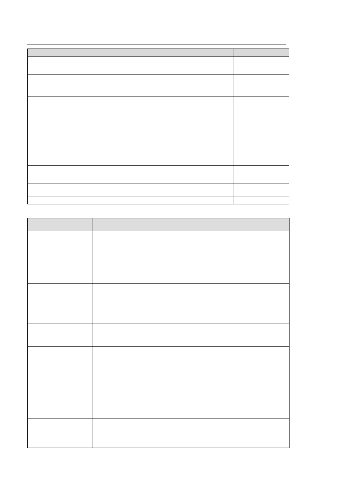
Edition Revision History
Edit.
Rev.
Date
Description
Where
1 - 2011/05/20
First Edition (V 1.00)
Corresponding with FA-9500 Operation Manual
3rd or later.
2 2011/08/19
Added FA-95CO option
2 1 2011/10/18
Revised AVO Scene Cut Detection frame delay,
and Forced Field frame delay settings
7-5-2-1
7-10-1
3 2011/12/07
Closed captioning
CEA608, S334-1, CEA708 compatible
7-10-13~7-14,
7-16~7-21, 13
4 2011/12/16
Added FA-95D-D and FA-95DE-E options
Enhanced Audio processing feature
Added PAL-M support
7-15, 8-1-2, 8-2-3,
8-3-5, 8-9, 8-10-3,
etc.
5 2012/02/16
Added FA-95AIO option
7-6-2, 7-7-1, 7-8-5,
7-10-3, 7-15, 7-17,
7-17-3, 7-17-5
5 1 2012/03/06
Deleted NTSC SETUP exceptional condition
Text corrections
7-10-14, 8-5-1, etc.
6 2012/03/26
Added Logo feature
7-9-1
7 2012/06/
Enhanced FA-95DE-E option.
Added AFD support. (S2016/VI/WSS)
CONV2 modified to Up/Down/Cross converter.
4-2-5, 7-3, 7-4,
7-10-14~7-10-19,
7-14, 7-16, 7-18, etc.
7 1 2013/01/28
- (Software upgraded to ver. 5.01)
The below software
version list
8 2013/06/06
Added FA-95ALA option and FA-9520 support.
Version
*1
Supported
Feature/Option
Note
FPGA:1.00
SOFT:1.00
FA-95PS
FA-95DACBL
First edition
FA-95RU is compatible with FA-9500 Software version
2.0 or higher.
FPGA1:1.00 or higher
SOFT: 1.10 or higher
FA-95CO
Supports FA-95CO option
FA-9500 with FA-95CO support is:
FPGA1: 1.50 or higher
FPGA2: 1.29 or higher
FPGA3: 1.01 or higher
SOFT: 2.10 or higher
FPGA1: 1.00 or higher
SOFT: 1.20 or higher
AVO Scene Cut Dection
Modified frame delay settings for Forced Field function
Corrected a bug on AUTO LOAD
Compatible with FA-9500 software version:
FPGA1: 1.55 or higher
FPGA2: 1.30 or higher
FPGA3:1.01 or higher
SOFT: 2.22 or higher
FPGA1: 1.00 or higher
SOFT: 1.30 or higher
Closed captioning
CEA608, S334-1, CEA708 compatible
Revised menu display upon switching VIDEO/AUDIO
menus.
FPGA1: 1.00 or higher
SOFT: 2.00 or higher
FA-95D-D
FA-95DE-E
Supports FA-95D-D and FA-95DE-E options
Supports PAL-M
Compatible with FA-9500 software version:
FPGA1: 2.08 or higher
FPGA2: 3.00 or higher
FPGA3:1.01 or higher
SOFT: 3.00 or higher
FPGA1:1.00 or higher
SOFT: 3.00 or higher
FA-95AIO
Supports FA-95AIO option
Compatible with FA-9500 software version:
FPGA1:2.28or higher
FPGA2: 4.10 or higher
FPGA3: 1.01 or higher
SOFT: 4.00 or higher
FPGA1:1.00 or higher
SOFT: 4.00 or higher
Logo Generator
Supports Logo Generator
Compatible with FA-9500 software version:
FPGA1:2.30 or higher
FPGA2: 4.10 or higher
FPGA3: 1.02 or higher
Software Version and Supported Options
2
Page 3
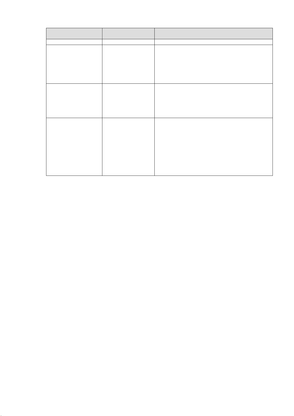
Version
*1
Supported
Feature/Option
Note
SOFT: 5.00 or higher
FPGA1:1.00 or higher
SOFT: 5.00 or higher
Added performance
features
Supports S2016/VI/WSS AFD,
CONV2 to Up/Down/Cross converter, and FA-95DE-E
option enhanced encoding function.
Compatible with FA-9500 software version:
FPGA1: 3.14 or higher
FPGA2: 5.02 or higher
FPGA3: 1.02 or higher
SOFT: 6.00 or higher
FPGA1:1.00 or higher
SOFT: 5.01 or higher
-
Corrected improper AUDIO DELAY displayed after CONV
DELAY ADJ is turned on.
Compatible with FA-9500 software version:
FPGA1: 3.14 or higher
FPGA2: 5.02 or higher
FPGA3: 1.02 or higher
SOFT: 6.00 or higher
FPGA1:1.00 or higher
SOFT: 6.00 or higher
FA-9520
FA-95ALA
Enabled control function for both FA-9520 and FA-9500.
Compatible with FA-9500 software versions:
FPGA1: 3.20 or higher
FPGA2: 5.20 or higher
FPGA3: 1.02 or higher
SOFT: 8.00 or higher
Compatible with FA-9520 software versions:
FPGA1: 1.10 or higher
FPGA2: 1.10 or higher
FPGA3: 1.00 or higher
SOFT: 2.00 or higher (in FA-9520 mode)
SOFT: 8.00 or higher (in FA-9500 mode)
*1 Version information can be seen in the FA-95RU INFO menu (See section 6-1-2).
Refer to the Operation Manual of the connected FA-9500/FA-9520 for the software version
verification procedure.
3
Page 4
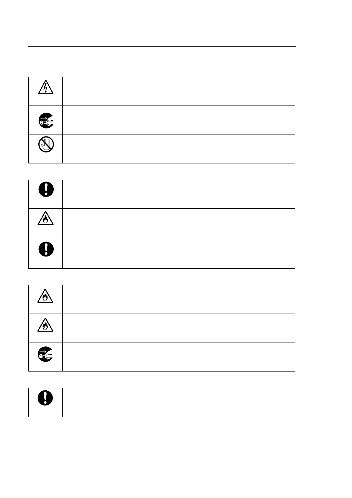
Precautions
Operate unit only on the specified supply voltage.
Disconnect power cord by connector only. Do not pull on cable portion.
Do not place or drop heavy or sharp-edged objects on power cord. A damaged cord
can cause fire or electrical shock hazards. Regularly check power cord for
excessive wear or damage to avoid possible fire / electrical hazards.
Ensure unit is properly grounded at all times to prevent electrical shock hazard.
Do not ground the unit to gas lines, units, or fixtures of an explosive or dangerous
nature.
Ensure power cord is firmly plugged into AC outlet.
Do not operate unit in hazardous or potentially explosive atmospheres. Doing so
could result in fire, explosion, or other dangerous results.
Do not allow liquids, metal pieces, or other foreign materials to enter the unit. Doing
so could result in fire, other hazards, or unit malfunction.
If foreign material does enter the unit, turn power off and disconnect power cord
immediately. Remove material and contact authorized service representative if
damage has occurred.
Handle with care to avoid shocks in transit. Shocks may cause malfunction. When
you need to transport the unit, use the original packing materials or alternate
adequate packing.
Stop
Caution
Hazard
Hazard
Caution
Hazard
Caution
Caution
Important Safety Warnings
[Power]
[Grounding]
[Operation]
[Transportation]
4
Page 5
[Circuitry Access]
Do not remove covers, panels, casing, or access circuitry with power applied to the
unit! Turn power off and disconnect power cord prior to removal. Internal servicing /
adjustment of unit should only be performed by qualified personnel.
Do not touch any parts / circuitry with a high heat factor.
Capacitors can retain enough electric charge to cause mild to serious shock, even
after power is disconnected. Capacitors associated with the power supply are
especially hazardous. Avoid contact with any capacitors.
Unit should not be operated or stored with cover, panels, and / or casing removed.
Operating unit with circuitry exposed could result in electric shock / fire hazards or
unit malfunction.
If abnormal smells or noises are noticed coming from the unit, turn power off
immediately and disconnect power cord to avoid potentially hazardous conditions. If
problems similar to above occur, contact authorized service representative before
attempting to again operate unit.
To rack mount or ground the unit, or to install rubber feet, do not use screws or
materials other than those supplied. Otherwise, it may cause damage to the internal
circuits or components of the unit. If you remove the rubber feet attached on the unit,
do not reinsert the screws securing the rubber feet.
The consumables used in unit must be replaced periodically. For further details on
which parts are consumables and when they should be replaced, refer to the
specifications at the end of the Operation Manual. Since the service life of the
consumables varies greatly depending on the environment in which they are used,
they should be replaced at an early date. For details on replacing the consumables,
contact your dealer.
Caution
Hazard
Stop
Caution
Caution
[Potential Hazards]
[Rack Mount Brackets, Ground Terminal, and Rubber Feet]
[Consumables]
5
Page 6
Upon Receipt
IMPORTANT
Verify the software version of your FA-9500/FA-9520 that can be seen in the “Software
Version and Supported Options” on the inside front cover before starting the FA-95RU.
If the software version of your FA-9500/FA-9520 is different from that shown as
compatible with the FA-95RU, please contact your service agent or FOR-A
representative. The FA-9500/FA-9520 version information can be seen in the UNIT
Ver. menu of respective units.
This Operation Manual mainly describes the specific operation of the FA-95RU. Refer
to the FA-9500/FA-9520 Operation Manual for VIDEO and AUDIO menus that appear
differently according to the connected unit or unit mode.
ITEM
QTY
REMARKS
FA-95RU
1
Rack Mount Brackets
1 set
EIA standard type (Including 4 screws.)
AC Cord
1 set
(Incl. ladder strap/retaining clip assembly)
Operation Manual
1
Unpacking
FA-95RU units and their accessories are fully inspected and adjusted prior to shipment.
Operation can be performed immediately upon completing all required connections and
operational settings.
Check your received items against the packing lists below.
Check
Check to ensure no damage has occurred during shipment. If damage has occurred, or items
are missing, inform your supplier immediately.
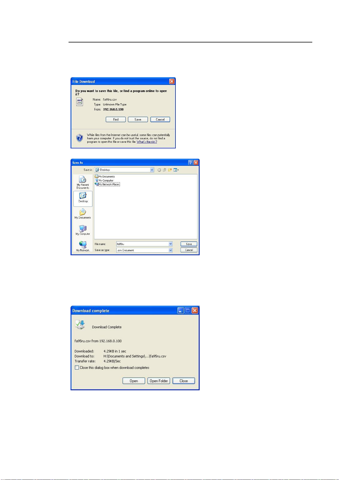
Trademark
Microsoft and Windows are either registered trademarks or trademarks of Microsoft
Corporation in the United States and/or other countries.
Pentium and Intel Core are trademarks of Intel Corporation in the U.S. and/or other countries.
Firefox is a registered trademark of the Mozilla Foundation.
Dolby is a trademark of Dolby Laboratories.
All other trademarks are trademarks or registered trademarks of their respective owners.
Rack Mounting
FA-95RU can be mounted to EIA standard rack units. When rack mounting a unit, remove the
rubber feet and use the accessory rack mount brackets (rack ears).
6
Page 7
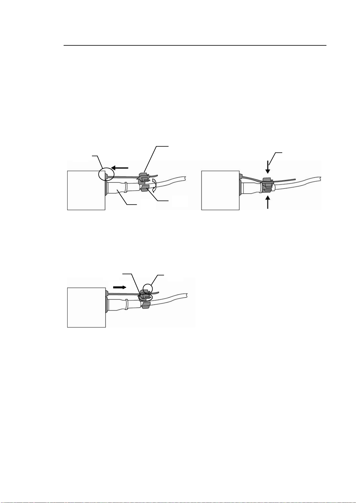
Installing the AC Cord Retaining Clip
2)
4)
3)
5)
6)
1)
2)
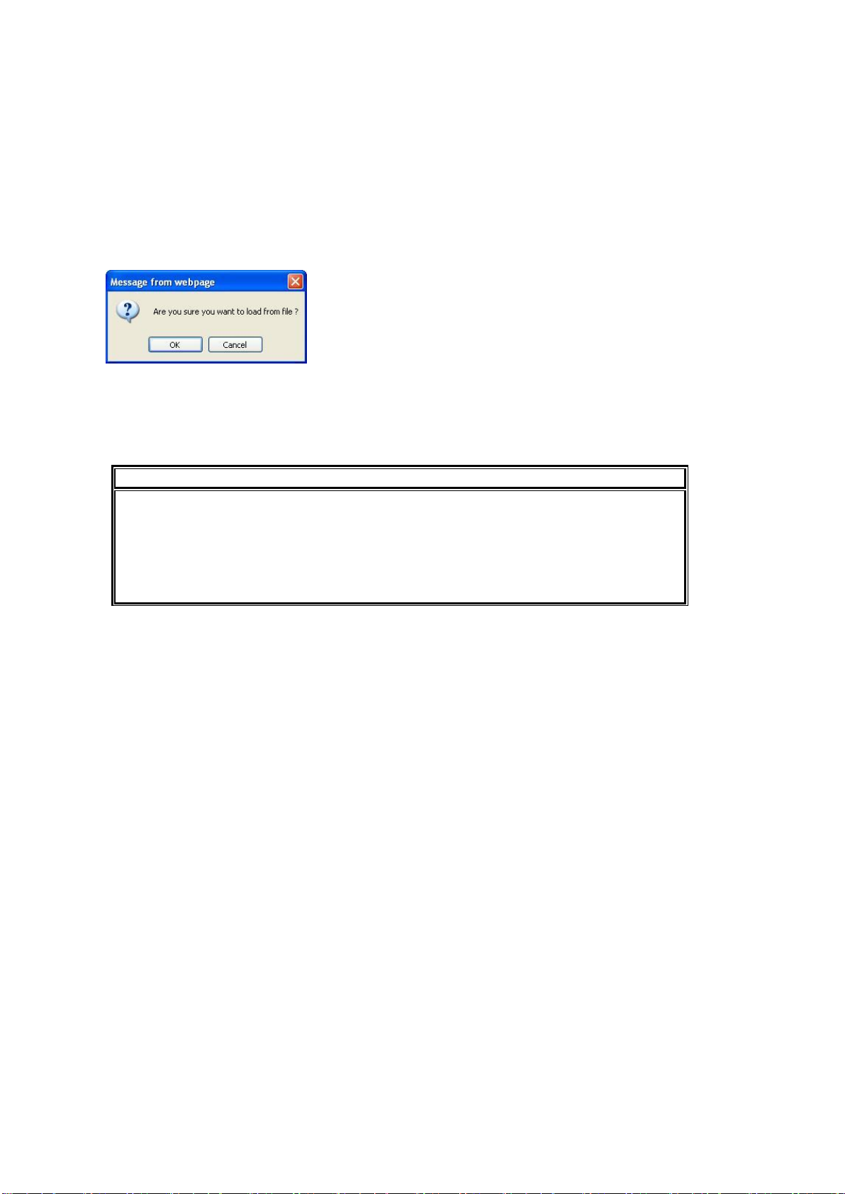
Secure the AC cord with the supplied ladder strap/retaining clip assembly to prevent accidental
removal from the FA-9500.
Installing the clip
1) Wrap the retaining clip around the AC cord. (with the anchor of the ladder strap toward the
unit.)
2) Insert the anchor into the hole next to the AC IN socket.
3) Lightly fasten the clip around the AC cord.
4) Plug in the power cord.
5) Slide the clip on the ladder strap toward the plug.
6) Fasten the clip tightly.
7) Gently pull on the AC cord to ensure it is secured.
Unpluging the AC cord
1) Push the tab on the retaining clip up to unfasten the clip.
2) Push the tab on the ladder strap up and slide the clip back.
3) Unplug the AC cord.
7
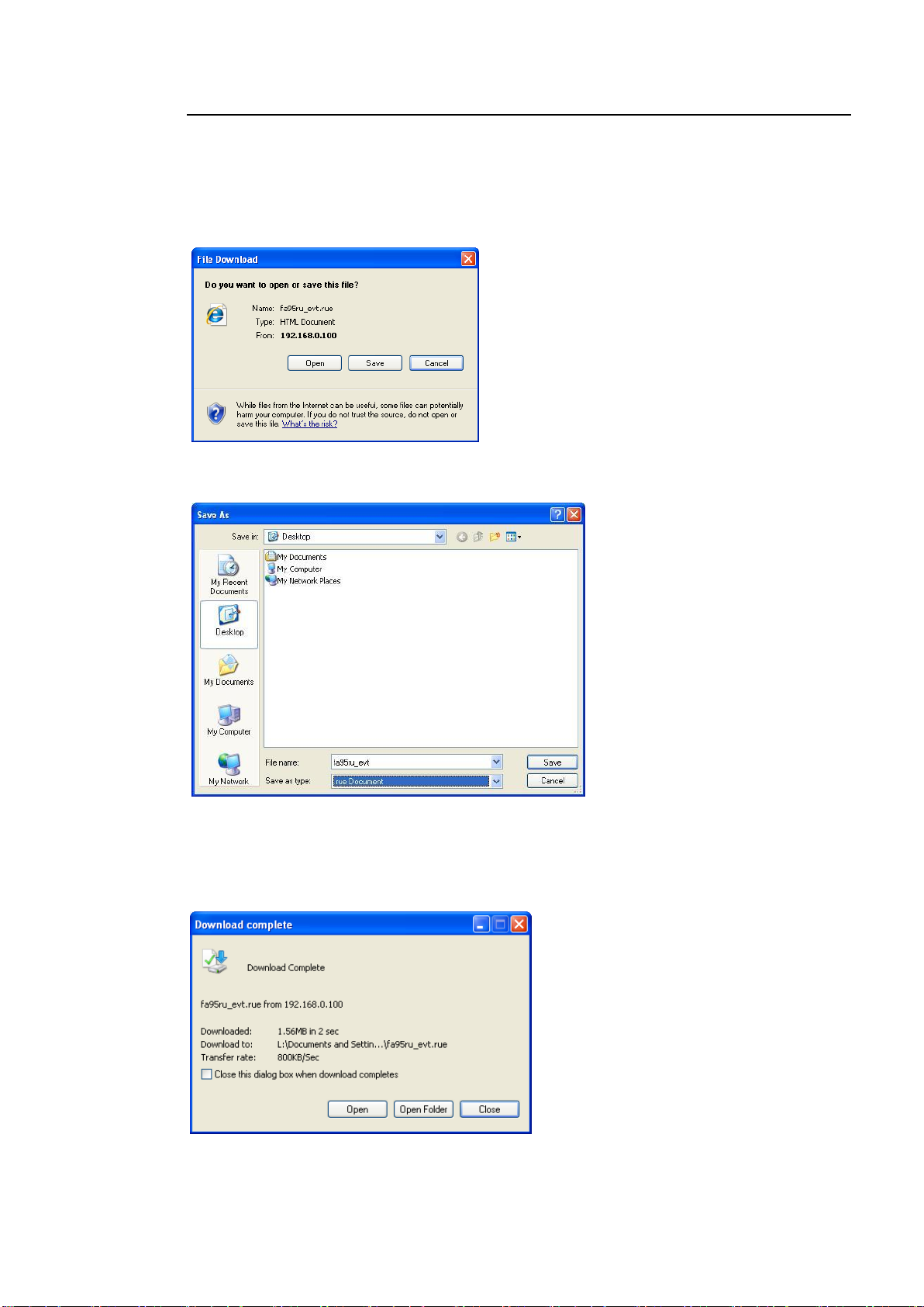
Page 8

Table of Contents
1. Prior to Starting ......................................................................................................................... 11
1-1. Welcome ............................................................................................................................ 11
1-2. Features ............................................................................................................................. 11
2. Panel Descriptions .................................................................................................................... 12
2-1. Front Panel ......................................................................................................................... 12
2-2. Rear Panel ......................................................................................................................... 13
2-3. Internal Settings ................................................................................................................. 14
2-3-1. Dipswitch Settings ....................................................................................................... 14
3. Connections .............................................................................................................................. 15
4. Front Panel Operations ............................................................................................................. 16
4-1. Powering ON ...................................................................................................................... 16
4-2. Basic Operations ................................................................................................................ 16
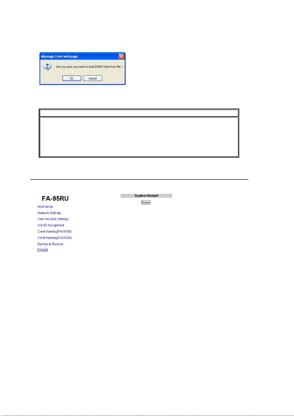
4-2-1. Accessing Menus ........................................................................................................ 17
4-2-2. Arrow Buttons.............................................................................................................. 18
4-2-3. Consecutive Viewing of Settings ................................................................................ 18
4-2-4. Changing Setting Values ............................................................................................ 19
4-2-5. Resetting to Default .................................................................................................... 20
4-2-6. Selecting 2-Channel Frame Synchronizers (FA-9520) .............................................. 21
4-2-7. Operation Lock Function (FA-9520) ........................................................................... 23
5. Establishing Connection with the FA-9500/FA-9520 ................................................................ 24
5-1. Unit ID Selection Mode ...................................................................................................... 24
5-2. IP Address Selection Mode ................................................................................................ 24
5-3. CONNECT STATE ............................................................................................................. 25
6. Changing and Viewing FA-95RU Settings ................................................................................ 26
6-1. MU SELECT Button Menus ............................................................................................... 26
6-1-1. FRONT PANEL SET ................................................................................................... 26
6-1-2. FA-95RU INFO ........................................................................................................... 26
6-1-3. FA-95RU NET WORK INFO ....................................................................................... 26
6-2. Other Settings & Information (STATUS/OTHER) .............................................................. 27
6-2-1. FRONT OPERATION ................................................................................................. 27
6-3. FA-9500 / FA-9520 Ver. ..................................................................................................... 27
7. Event Memory ........................................................................................................................... 28
7-1. EVENT LOAD .................................................................................................................... 28
7-2. EVENT SAVE ..................................................................................................................... 29
7-3. EVENT SETUP .................................................................................................................. 29
7-4. Parameters That Are Not Stored in Event Memories ........................................................ 30
7-5. Note on Event Memory Operation ..................................................................................... 30
8. WEB Browser Settings .............................................................................................................. 31
8-1. Information ......................................................................................................................... 31
8-2. Network Settings ................................................................................................................ 32
8
Page 9

8-3. User Account Settings ....................................................................................................... 32
8-4. Unit ID Assignment ............................................................................................................ 33
8-5. Event Naming (FA-9500)................................................................................................... 33
8-6. Event Naming (FA-9520)................................................................................................... 34
8-7. Backup & Restore ............................................................................................................. 34
8-7-1. Configuration Data Backup ........................................................................................ 35
8-7-2. Event Data Backup (FA-9500/FA9520) ..................................................................... 37
8-8. Restart ............................................................................................................................... 38
9. System Requirements .............................................................................................................. 39
10. FA-95RU Ancillary Data Packet Name List ............................................................................ 40
10-1. AFD Code Abbreviations ................................................................................................. 42
11. Specifications and Dimensions .............................................................................................. 44
11-1. Unit Specifications ........................................................................................................... 44
11-2. External Dimensions ....................................................................................................... 44
Index ............................................................................................................................................. 45
9
Page 10

Page 11

1. Prior to Starting
1-1. Welcome
Congratulations! By purchasing FA-95RU Remote Control Unit you have entered the world of
FOR-A and its many innovative products. Thank you for your patronage and we hope you will
turn to FOR-A products again and again to satisfy your video and audio needs.
FOR-A provides a wide range of products, from basic support units to complex system
controllers, which have been increasingly joined by products for computer video based systems.
Whatever your needs, talk to your FOR-A representative. We will do our best to be of continuing
service to you.
1-2. Features
The FA-95RU is a remote control unit that controls FA-9500/FA-9520 Frame Synchronizer units.
Control over FA-9500/FA-9520 via ethernet
Up to 100 FA-9500/FA-9520 units can be connected to be selected for control
IP address FA-9500/FA-9520 selection and control
Simultaneous control over one FA-9500/FA-9520 from five FA-95RU units
Storage and recall of up to 100 events each for FA-9500 and FA-9520
PC backup of event memory
11
Page 12
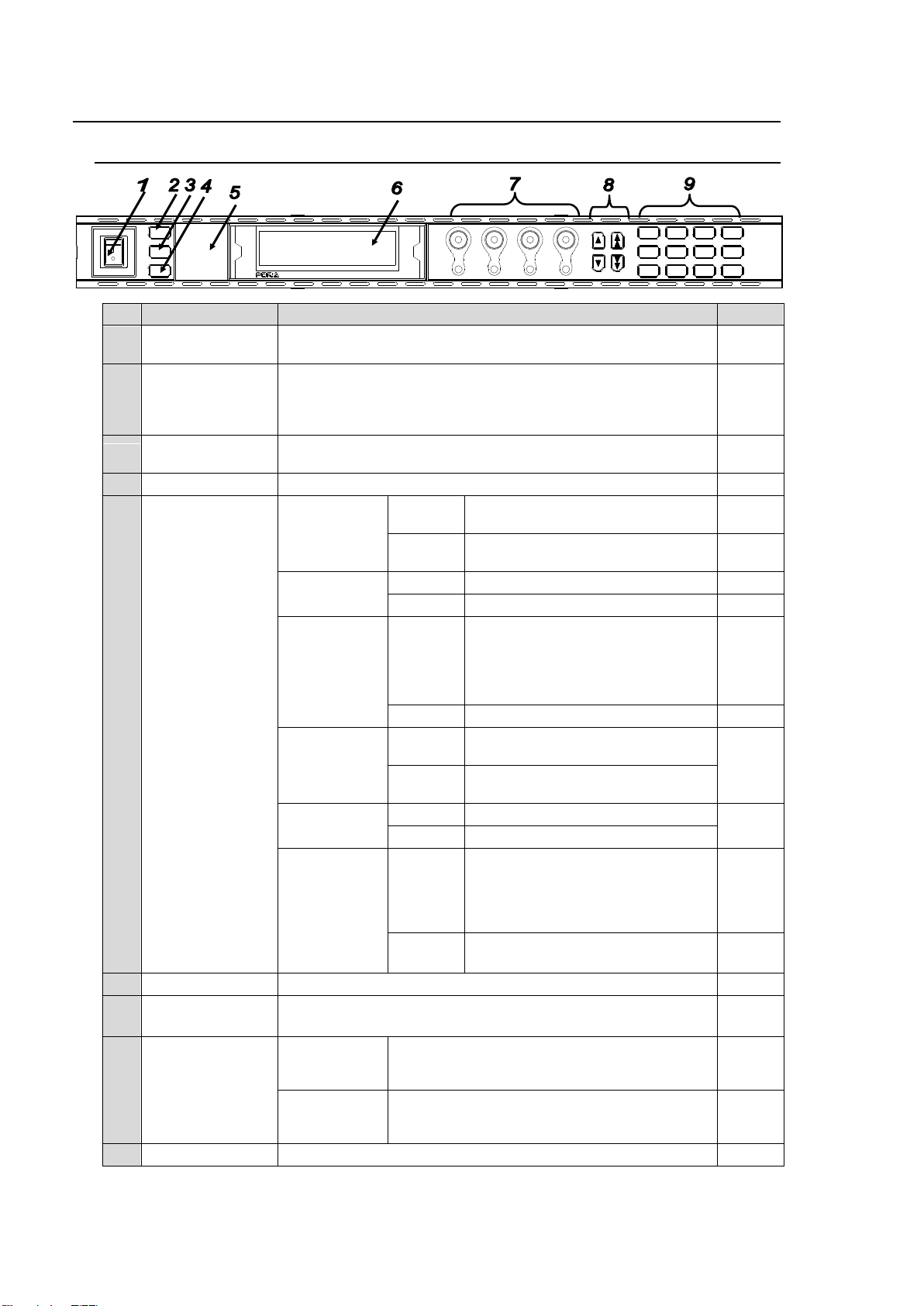
No.
Name
Description
Ref.
1
POWER switch
Used to turn the unit ON / OFF. Pressing the "|" side turns on
the power.
4-1
2
LOCK button
Lit when pressed, and the buttons and controls on the front
panel except this LOCK button are disabled.
To enable the disabled buttons and controls, press and hold
this button down for several seconds.
3
MU SELECT
button
Used to open an FA-9500/FA-9520 control selection menu.
6-1
4
EVENT button
Used to save and load events.
7
5
Status indicator
VIDEO IN
Lit green
An input signal is present in the
connector selected in the menu.
Unlit
An input signal is not present in the
connector selected in the menu.
AUDIO IN
Lit green
An audio signal is present.
Unlit
No audio signal is present.
GENLOCK
Lit green
A genlock signal input is present.
(Unlit if SYNCHRO is set to
INPUT. See FS MODE SET in the
FA-9500/FA-9520 Operation
Manual for details.)
Unlit
No genlock signal input is present.
REMOTE
Lit green
FA-9500/FA-9520 is/are
connected.
5
Unlit
No FA-9500/FA-9520 is
connected.
BY-PASS
Lit red
In BY-PASS mode.
Unlit
In operation mode.
FAN ALARM
Lit red
Fan(s) on FA-95RU and/or
FA-9500/FA-9520 have failed.
Turn the power of the unit OFF,
and replace the failed fans if
needed.
6-1-2,
Unlit
All fans are operating normally.
6-1-2,
6
Menu display
Used to display menus and make operational settings
4-2
7
Controls (F1-F4)
UNITY buttons
Used to change operational settings. Turn and select values.
The Unity buttons return the settings to the default values.
4-2
8
Arrow buttons
Single-arrow
buttons
Used to move between parameters.
(Indicators light up to indicate the accessible
direction.)
4-2
Double-arrow
buttons
Used to move between menus (same as the
menu buttons). (Indicators light up to indicate
the accessible direction.)
4-2
9
Menu buttons
Used to select menus.
4-2
DISPLAY AREA
POWER
ON
OFF
LOCK
MU
SELECT
EVENT
BY-PASSVIDEO IN
AUDIO IN FAN ALARM
GENLOCK
REMOTE
F 1
F 2
F 3
F 4
R EM O T E C O NT R O L U NI TF A -9 5 R U
F1
F2
F3
F4
UNITYUNITY UNITY UNITY
PROCESS
SDI AUDIO
C C
AES AUDIO
CONV1
ANALOG
CONV2
MASTER
AVO
MAPPING
CLIP
DELAY
DOWNMIX
IN SEL OUT SEL
MODE
AUDIO OP
VIDEO OP VIDEO SYS
AUDIO SYS
STATUS
OTHER
VIDEO
AUDIO
2. Panel Descriptions
2-1. Front Panel
12
Page 13
No.
Name
Description
Ref.
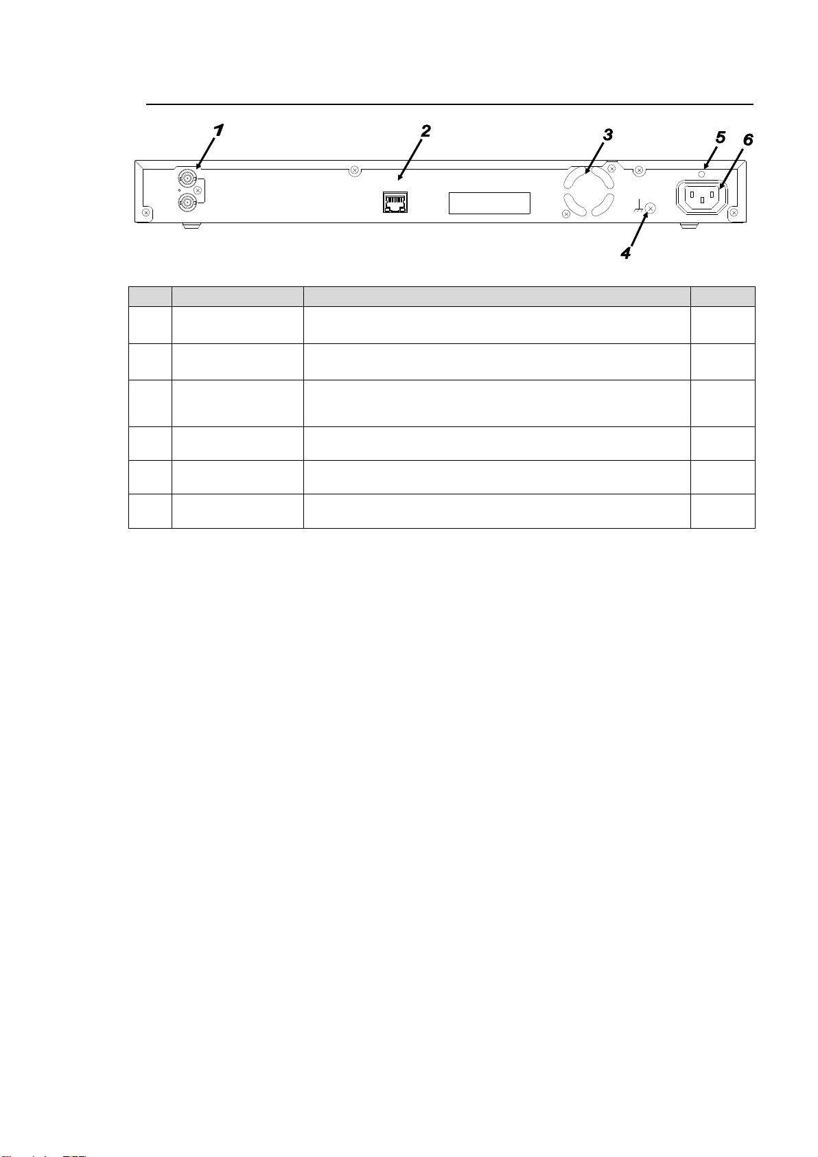
1
TO MU
(FA-9000/9100)
Used to control an FA-9000/9100 series unit.
Not functioning yet.
2
TO MU
(FA-9500)
A LAN connector for FA-9500/FA-9520 control
Set the unique IP address and connect to the network.
3,
8-2
3
FAN
Used to air-cool the unit to prevent overheating. Do not block
the ventilation with other equipment or objects. The FAN
ALARM on the front panel lights up if the fan fails.
2-1 #5
6-1-2
4
Ground Terminal
Used to ground the unit to protect operators against static
electricity and electrical shock.
5
AC cord retaining
clip anchor hole
Used to anchor the AC cord retaining clip.
6
AC IN
Used to connect the unit to an AC power source.
(AC100V-240V 50/60Hz)
IN
OUT
(FA-90 00/9100)
TO MU
TO MU
(FA-950 0)
(10/100 /1000BASE-T X)
RATING LABEL
AC100-240 V 50/60Hz IN
2-2. Rear Panel
13
Page 14
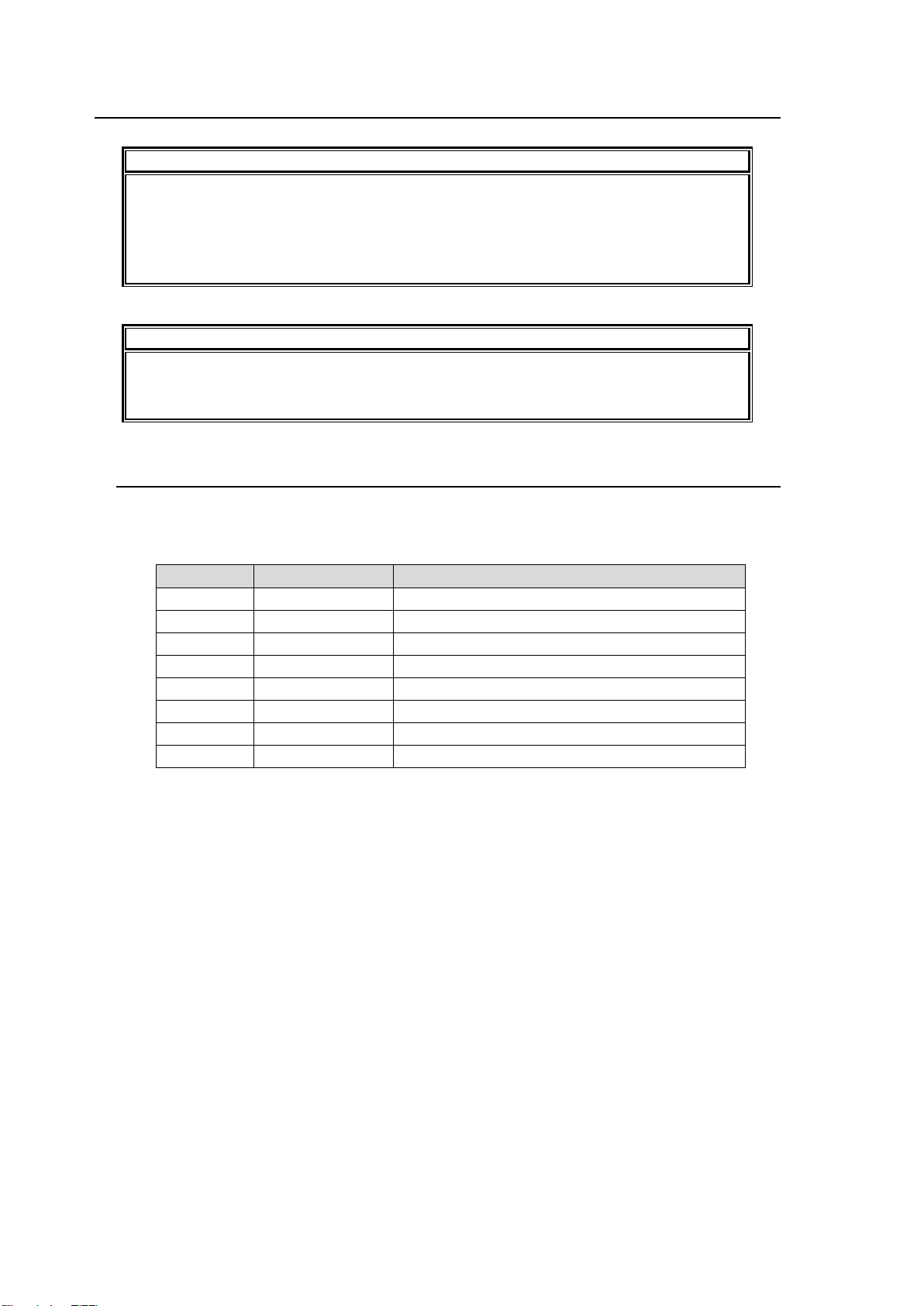
IMPORTANT
Note that internal switch settings should not be changed from factory defaults. If you
have accidentally changed the settings, return them to the factory default settings as
shown in this section.
Be sure to have qualified technical personnel perform the settings and adjustments in
the interior, or contact your dealer.
CAUTION
Do not access any internal cards while the unit is powered ON. Always power OFF all
connected units / disconnect power cords prior to accessing the interior. To protect
boards from electrostatic damage, do not touch the components on the boards.
Pin No.
Default setting
Setting
1
OFF
Do not change.
2
OFF
Do not change.
3
OFF
Do not change.
4
OFF
Do not change.
5
OFF
Do not change.
6
OFF
Do not change.
7
OFF
Do not change.
8
OFF
Do not change.
2-3. Internal Settings
2-3-1. Dipswitch Settings
The following settings can be made at the dipswitches on MAIN CARD inside the unit.
Dipswitch S3 Settings
14
Page 15
DISPLAY AREA
POWER
ON
OFF
LOCK
MU
SELECT
EVENT
BY-PASSVIDEO IN
AUDIO INFAN ALARM
GENLOCK
REMOTE
F 1
F 2
F 3
F 4
REM OTE CONTR OL U NITFA-9 5RU
F1F2F3
F4
UNITYUNITY UNITY UNITY
PROCESS
SDI AUDIO
C C
AES AUDIO
CONV1
ANALOG
CONV2
MASTER
AVO
MAPPING
CLIP
DELAY
DOWNMIX
IN SEL OUT SEL
MODE
AUDIO OP
VIDEO OP VIDEO SYS
AUDIO SYS
STATUS
OTHER
VIDEO
AUDIO
DISPLAY AREA
POWER
ON
OFF
LOCK
MU
SELECT
EVENT
BY-PASSVIDEO IN
AUDIO INFAN ALARM
GENLOCK
REMOTE
F 1
F 2
F 3
F 4
REM OTE CONTR OL U NITFA-9 5RU
F1F2F3
F4
UNITYUNITY UNITY UNITY
PROCESS
SDI AUDIO
C C
AES AUDIO
CONV1
ANALOG
CONV2
MASTER
AVO
MAPPING
CLIP
DELAY
DOWNMIX
IN SEL OUT SEL
MODE
AUDIO OP
VIDEO OP VIDEO SYS
AUDIO SYS
STATUS
OTHER
VIDEO
AUDIO
DISPLAY AREA
POWER
ON
OFF
LOCK
MU
SELECT
EVENT
BY-PASSVIDEO IN
AUDIO INFAN ALARM
GENLOCK
REMOTE
F 1
F 2
F 3
F 4
REM OTE CONTR OL U NITFA-9 5RU
F1F2F3
F4
UNITYUNITY UNITY UNITY
PROCESS
SDI AUDIO
C C
AES AUDIO
CONV1
ANALOG
CONV2
MASTER
AVO
MAPPING
CLIP
DELAY
DOWNMIX
IN SEL OUT SEL
MODE
AUDIO OP
VIDEO OP VIDEO SYS
AUDIO SYS
STATUS
OTHER
VIDEO
AUDIO
DISPLAY AREA
POWER
ON
OFF
LOCK
MU
SELECT
EVENT
BY-PASSVIDEO IN
AUDIO INFAN ALARM
GENLOCK
REMOTE
F 1
F 2
F 3
F 4
REM OTE CONTR OL U NITFA-9 5RU
F1F2F3
F4
UNITYUNITY UNITY UNITY
PROCESS
SDI AUDIO
C C
AES AUDIO
CONV1
ANALOG
CONV2
MASTER
AVO
MAPPING
CLIP
DELAY
DOWNMIX
IN SEL OUT SEL
MODE
AUDIO OP
VIDEO OP VIDEO SYS
AUDIO SYS
STATUS
OTHER
VIDEO
AUDIO
DISPLAY AREA
POWER
ON
OFF
LOCK
MU
SELECT
EVENT
BY-PASSVIDEO IN
AUDIO INFAN ALARM
GENLOCK
REMOTE
F 1
F 2
F 3
F 4
REM OTE CONTR OL U NITFA-9 5RU
F1F2F3
F4
UNITYUNITY UNITY UNITY
PROCESS
SDI AUDIO
C C
AES AUDIO
CONV1
ANALOG
CONV2
MASTER
AVO
MAPPING
CLIP
DELAY
DOWNMIX
IN SEL OUT SEL
MODE
AUDIO OP
VIDEO OP VIDEO SYS
AUDIO SYS
STATUS
OTHER
VIDEO
AUDIO
MASTER
CONV2
OUT SEL
MODE
VIDEO
AUDIO
ANALOG
CONV1
IN SEL
DOWNMIX
STATUS
OTHER
C C
AES AUDIO
CLIP
DELAY
AUDIO SYS
VIDEO SYS
AUDIO OP
VIDEO OP
MAPPING
A V O
PROCESS
SDI AUDIO
F4
UNITYUNITYUNITYUNITY
F3
F2
F1
F A - 9 5 0 0
DISPLAY AREA
HD / S D FRAME S YSNCHRONIZ ER
VIDEO IN
AUDIO IN
GENLOCK
REMOTE
FAN ALARM
DC POWER
BY-PASS
LOCK
EVENT
ON
OFF
POWER
F1
F2
F3
F4
MASTER
CONV2
OUT SEL
MODE
VIDEO
AUDIO
ANALOG
CONV1
IN SEL
DOWNMIX
STATUS
OTHER
C C
AES AUDIO
CLIP
DELAY
AUDIO SYS
VIDEO SYS
AUDIO OP
VIDEO OP
MAPPING
A V O
PROCESS
SDI AUDIO
F4
UNITYUNITYUNITYUNITY
F3
F2
F1
F A - 9 5 0 0
DISPLAY AREA
HD / S D FRAME S YSNCHRONIZ ER
VIDEO IN
AUDIO IN
GENLOCK
REMOTE
FAN ALARM
DC POWER
BY-PASS
LOCK
EVENT
ON
OFF
POWER
F1
F2
F3
F4
MASTER
CONV2
OUT SEL
MODE
VIDEO
AUDIO
ANALOG
CONV1
IN SEL
DOWNMIX
STATUS
OTHER
C C
AES AUDIO
CLIP
DELAY
AUDIO SYS
VIDEO SYS
AUDIO OP
VIDEO OP
MAPPING
A V O
PROCESS
SDI AUDIO
F4
UNITYUNITYUNITYUNITY
F3
F2
F1
F A - 9 5 0 0
DISPLAY AREA
HD / S D FRAME S YSNCHRONIZ ER
VIDEO IN
AUDIO IN
GENLOCK
REMOTE
FAN ALARM
DC POWER
BY-PASS
LOCK
EVENT
ON
OFF
POWER
F1
F2
F3
F4
MASTER
CONV2
OUT SEL
MODE
VIDEO
AUDIO
ANALOG
CONV1
IN SEL
DOWNMIX
STATUS
OTHER
C C
AES AUDIO
CLIP
DELAY
AUDIO SYS
VIDEO SYS
AUDIO OP
VIDEO OP
MAPPING
A V O
PROCESS
SDI AUDIO
F4
UNITYUNITYUNITYUNITY
F3
F2
F1
F A - 9 5 0 0
DISPLAY AREA
HD / S D FRAME S YSNCHRONIZ ER
VIDEO IN
AUDIO IN
GENLOCK
REMOTE
FAN ALARM
DC POWER
BY-PASS
LOCK
EVENT
ON
OFF
POWER
F1
F2
F3
F4
MASTER
CONV2
OUT SEL
MODE
VIDEO
AUDIO
ANALOG
CONV1
IN SEL
DOWNMIX
STATUS
OTHER
C C
AES AUDIO
CLIP
DELAY
AUDIO SYS
VIDEO SYS
AUDIO OP
VIDEO OP
MAPPING
A V O
PROCESS
SDI AUDIO
F4
UNITYUNITYUNITYUNITY
F3
F2
F1
F A - 9 5 0 0
DISPLAY AREA
HD / S D FRAME S YSNCHRONIZ ER
VIDEO IN
AUDIO IN
GENLOCK
REMOTE
FAN ALARM
DC POWER
BY-PASS
LOCK
EVENT
ON
OFF
POWER
F1
F2
F3
F4
MASTER
CONV2
OUT SEL
MODE
VIDEO
AUDIO
ANALOG
CONV1
IN SEL
DOWNMIX
STATUS
OTHER
C C
AES AUDIO
CLIP
DELAY
AUDIO SYS
VIDEO SYS
AUDIO OP
VIDEO OP
MAPPING
A V O
PROCESS
SDI AUDIO
F4
UNITYUNITYUNITYUNITY
F3
F2
F1
F A - 9 5 0 0
DISPLAY AREA
HD / S D FRAME S YSNCHRONIZ ER
VIDEO IN
AUDIO IN
GENLOCK
REMOTE
FAN ALARM
DC POWER
BY-PASS
LOCK
EVENT
ON
OFF
POWER
F1
F2
F3
F4
MASTER
CONV2
OUT SEL
MODE
VIDEO
AUDIO
ANALOG
CONV1
IN SEL
DOWNMIX
STATUS
OTHER
C C
AES AUDIO
CLIP
DELAY
AUDIO SYS
VIDEO SYS
AUDIO OP
VIDEO OP
MAPPING
A V O
PROCESS
SDI AUDIO
F4
UNITYUNITYUNITYUNITY
F3
F2
F1
F A - 9 5 0 0
DISPLAY AREA
HD / S D FRAME S YSNCHRONIZ ER
VIDEO IN
AUDIO IN
GENLOCK
REMOTE
FAN ALARM
DC POWER
BY-PASS
LOCK
EVENT
ON
OFF
POWER
F1
F2
F3
F4
PC
Hub
FA-95RU control PC
FA-95RU
F0A-9500/FA-952
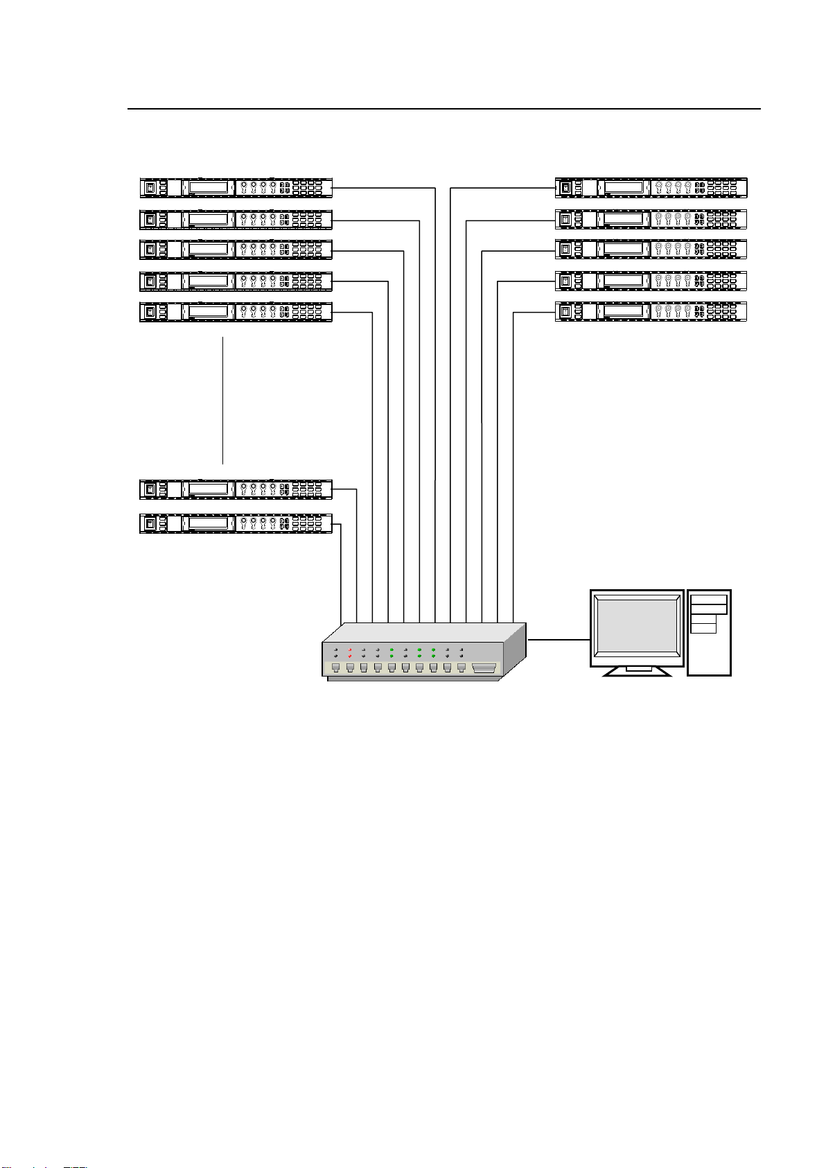
3. Connections
Specify unique IP addresses for all devices connected to the network.
See section 8-2. Network Settings for details on setting IP addresses.
One FA-9500/FA-9520 unit can be controlled by up to 5 units of FA-95RU maximum.
15
Page 16
U N I T I D S E L
801
M U I D : 1
I P : 1 9 2 . 1 6 8 . 0 . 1
NAME: FA- 9 5 0 0 / F A - 9520
F 3 : S E T F 4 : C A N C E L
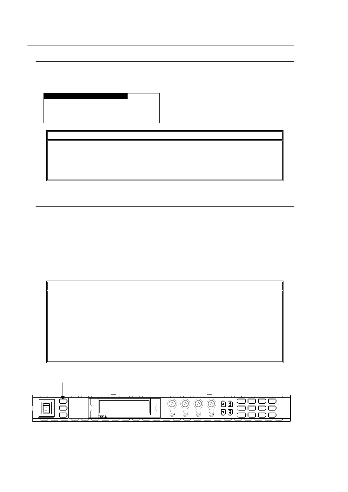
IMPORTANT
Operation by the FA-95RU is ineffective, except for the ability to change its own
settings, unless it is connected to an FA-9500/FA-9520. To enable operation by the
FA-95RU, select and connect an FA-9500/FA-9520 to be controlled. See section 5.
“Establishing Connection with the FA-9500/FA-9520” for details on connecting
FA-9500/FA-9520 units.
IMPORTANT
Make sure that the LOCK indicator on the front panel is turned off before starting an
operation with the connected FA-9500 or FA-9520 in FA-9500 mode. If the LOCK
indicator is lit, all operations on the front panel except the LOCK button are disabled.
Press and hold the LOCK button to enable operation.
See section 4-2-7. “Operation Lock Function (FA-9520)” for the lock function in the
FA-9520 in FA-9520 mode that is different from the above.
The description in Basic Operation starts based on an established connection. To
establish a connection with the FA-9500/FA-9520, see section 5. “Establishing
Connection with the FA-9500/FA-9520”.
DISPLAY AREA
POWER
ON
OFF
LOCK
MU
SELECT
EVENT
BY-PASSVIDEO IN
AUDIO IN FAN ALARM
GENLOCK
REMOTE
F 1
F 2
F 3
F 4
R EM O T E C ON T R OL UN I TF A - 95 R U
F1
F2
F3
F4
UNITYUNITY UNITY UNITY
PROCESS
SDI AUDIO
C C
AES AUDIO
CONV1
ANALOG
CONV2
MASTER
AVO
MAPPING
CLIP
DELAY
DOWNMIX
IN SEL OUT SEL
MODE
AUDIO OP
VIDEO OP VIDEO SYS
AUDIO SYS
STATUS
OTHER
VIDEO
AUDIO
LOCK button
4. Front Panel Operations
4-1. Powering ON
Turn the power ON after all system connections are complete. The indicators on the front panel
light up during startup. When startup is complete, the indicators will go off. The UNIT ID SEL
menu will appear if no FA-9500/FA-9520 is connected.
4-2. Basic Operations
This section explains how to select menus and parameters.
Most of the menus can be controlled by these basic operations. However, some menus work
differently. See the descriptions given for each menu for details.
The FA-95RU has two menu operation modes: NORMAL mode, in which setting changes
immediately take effect, and LIVE SAFE mode, in which some settings request confirmation
before changes take effect. NORMAL and LIVE SAFE modes can be selected in the FRONT
OPERATION menu (sec. 6-2-1). Factory default is NORMAL mode. Menus that request setting
confirmation are shown in the menu list in “Menu Buttons” in the FA-9500/FA-9520 Operation
Manual with a black circle (●).
16
Page 17
V I D E O P R O C A M P
1
V I D E O L E V E L : 1 0 0 . 0 %
C H R O M A L E V E L : 1 0 0 . 0 %
S E T U P / B L A C K : 0 . 0 %
H U E : 0 . 0 °
DISPLAY AREA
POWER
ON
OFF
LOCK
MU
SELECT
EVENT
BY-PASSVIDEO IN
AUDIO IN FAN ALARM
GENLOCK
REMOTE
F 1
F 2
F 3
F 4
R EM O TE C O NT R OL UN ITF A -9 5 R U
F1
F2
F3
F4
UNITYUNITY UNITY UNITY
PROCESS
SDI AUDIO
C C
AES AUDIO
CONV1
ANALOG
CONV2
MASTER
AVO
MAPPING
CLIP
DELAY
DOWNMIX
IN SEL OUT SEL
MODE
AUDIO OP
VIDEO OP VIDEO SYS
AUDIO SYS
STATUS
OTHER
VIDEO
AUDIO
Menu buttons
VIDEO/AUDIO
button
Parameter
Menu Title
Value
Page number
F 1
F 2
F 3
F 4
F A - 9 5 R UR E M O T E C O N T R O L U N I T
MASTER
CONV2
OUT SEL
MODE
VIDEO
AUDIO
ANALOG
CONV1
IN SEL
DOWNMIX
STATUS
OTHER
C C
AES AUDIO
CLIP
DELAY
AUDIO SYS
VIDEO SYS
AUDIO OP
VIDEO OP
MAPPING
A V O
PROCESS
SDI AUDIO
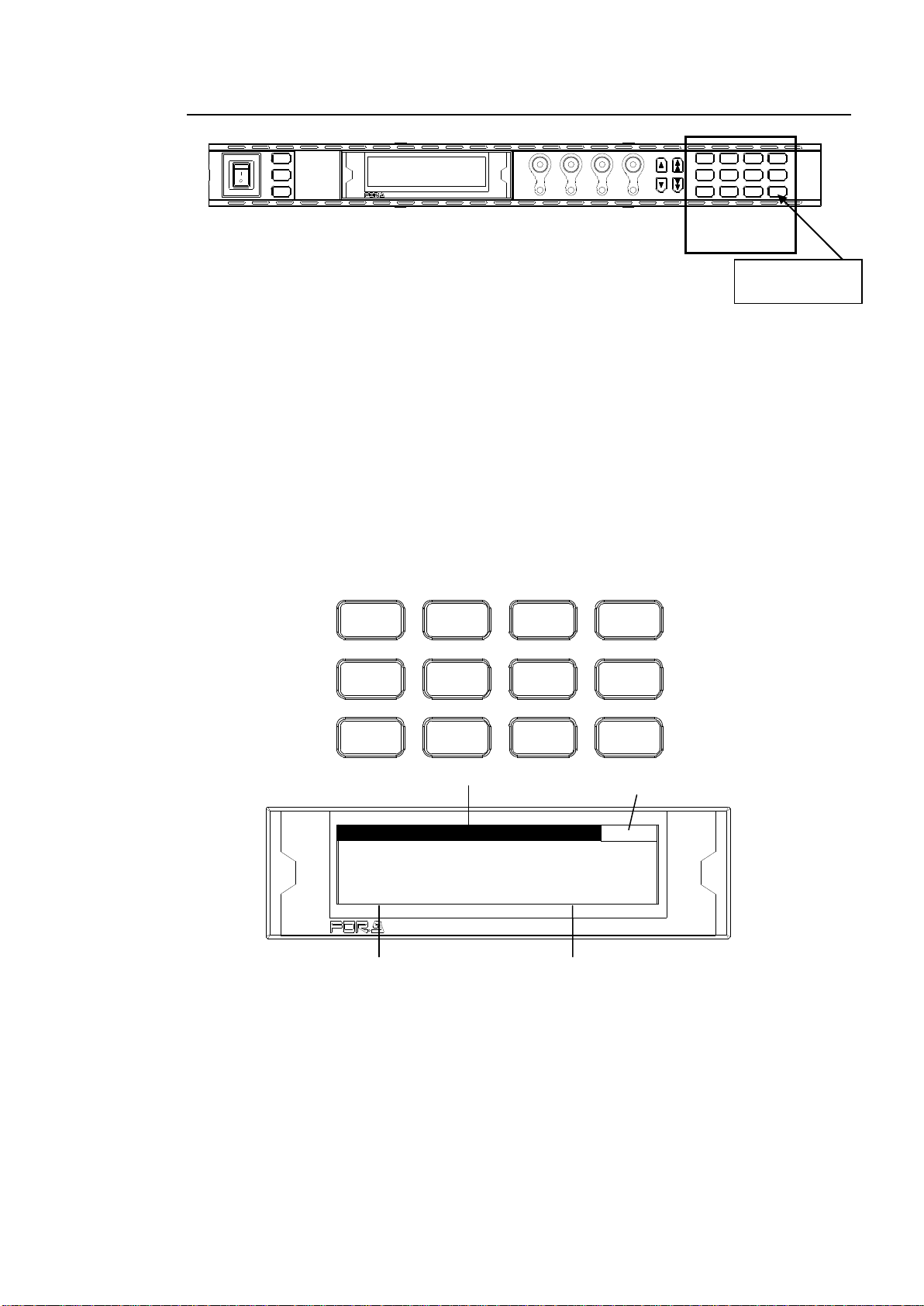
4-2-1. Accessing Menus
Every press of the VIDEO/AUDIO button alternates the menu button assignments between
video menus and audio menus. The button indicators light up green when the buttons are
accessible to video menus that are indicated on the top row of each menu button. They light
up orange when they are accessible to audio menus that are indicated on the bottom row of
each menu button.
Pressing a menu button displays the corresponding menu on the menu display. Menus are
divided into categories. The single-arrow buttons allow you to move between menus if the
selected menu button has multiple menu pages in the category. The single-arrow button
lights up when there are more menus to be accessed in the direction. If the single-arrow
button is unlit, the direction is not accessible.
The double-arrow buttons allow you to go to the first menu of the menu button.
Menu Buttons
In the example above, the PROCESS/SDI AUDIO button has been pressed, so that the
VIDEO PROC AMP menu is displayed.
17
Page 18

4-2-2. Arrow Buttons
Double-arrow buttons (up and down)
<NORMAL mode>
The double-arrow buttons allow you to go to the first menu of the video or audio menus that
are assigned to the respective menu buttons. These buttons can also navigate
STATUS/OTHER video related menus (designated by “◊” in the menu list).
<LIVE SAFE mode>
Button functions are the same as NORMAL mode, however, double-arrow buttons are
inoperative while single-arrow buttons are blinking (indicating the FA-9500/FA-9520 is in the
setting change confirming state, because a parameter in one of the menus requiring a setting
change confirmation has been changed).
Single-arrow buttons (up and down)
<NORMAL mode>
The single-arrow buttons allow you to move between menus within the menus that are
assigned to respective menu buttons.
When it reaches the last menu, the light goes off.
<LIVE SAFE mode>
Single-arrow buttons blink when a parameter in one of the menus requiring a setting change
confirmation is changed. To confirm the change, press the single down arrow button.
Pressing the single up arrow button cancels the change, and the parameter before change
will be displayed.
While single-arrow buttons are blinking, all buttons except single-arrow buttons are disabled
until either single-arrow button is pressed.
Menus that request setting confirmation are shown with a black circle (●) in the menu list in
the FA-9500/FA-9520 Operation Manual.
4-2-3. Consecutive Viewing of Settings
<NORMAL mode>
While a menu button is turned on, the menu display will be in consecutive display mode when
both single (up and down) arrow buttons are pressed simultaneously. Both single arrow
buttons blink when they are in consecutive display mode. To exit the mode, simultaneously
press both arrow buttons again. Then arrow buttons will stop blinking.
The single down and up arrow buttons, while in consecutive display mode, can consecutively
display all menus in which menu list settings can be changed, from the first to last or last to
first menu item. Meanwhile, holding down the single down or up arrow button also allows you
to consecutively view menus.
<LIVE SAFE mode>
Button functions are the same as NORMAL mode, however, consecutive display mode is
inoperative while single-arrow buttons are blinking (indicating the FA-9520 is in the setting
change confirming state, because a parameter in one of the menus requiring a setting
change confirmation has been changed). Consecutive display becomes operable when the
change is either confirmed or canceled.
Order of Consecutive Menu Display
VIDEO Menus (Lit green)
The single down-arrow button consecutively displays menu pages from VIDEO PROC AMP
of PROCESS to CONV2 ANC OUT1 of STATUS in the menu list in the FA-9500/FA-9520
Operation Manual. On the other hand, the single up-arrow button consecutively displays
menu pages from CONV2 ANC OUT1 of STATUS to VIDEO PROC AMP of PROCESS in the
menu list.
18
Page 19
V I D E O P R O C A M P
1
V I D E O L V L : 1 0 0 . 0 %
C H R O M A L V L : 1 0 0 . 0 %
S E T U P / B L A C K : 0 . 0 %
H U E : 0 . 0 °
V I D E O I N P U T S E T
47
I N S E L : S D I 1
L O S S : B A C K C O L O R
B A C K C O L O R : O F F
C H A N G E O V E R : D I S A B L E
DISPLAY AREA
POWER
ON
OFF
LOCK
MU
SELECT
EVENT
BY-PASSVIDEO IN
AUDIO IN FAN ALARM
GENLOCK
REMOTE
F 1
F 2
F 3
F 4
R EM O TE CO N TR O L U NI TF A - 95 R U
F1
F2
F3
F4
UNITYUNITY UNITY UN ITY
PROCESS
SDI AUDIO
C C
AES AUDIO
CONV1
ANALOG
CONV2
MASTER
AVO
MAPPING
CLIP
DELAY
DOWNMIX
IN SEL OUT SEL
MODE
AUDIO OP
VIDEO OP VIDEO SYS
AUDIO SYS
STATUS
OTHER
VIDEO
AUDIO
Control
F1 - F4
Parameter
Menu Title
Value
Page number
F 1
F 2
F 3
F 4
F A - 9 5 R UR E M O T E C O N T R O L U N I T
Parameter
Menu Title
Value
Page number
F 1
F 2
F 3
F 4
F A - 9 5 R UR E M O T E C O N T R O L U N I T
AUDIO Menus (Lit orange)
The single down-arrow button consecutively displays menu pages from SDI AUDIO GAIN of
SDI AUDIO to SOFT OPTION2 of OTHER in the menu list in the FA-9500/FA-9520 Operation
Manual. On the other hand, the single up-arrow button consecutively displays menu pages
from SOFT OPTION2 of OTHER to SDI AUDIO GAIN of SDI AUDIO in the menu list.
* The EVENT button-assigned menus cannot be consecutively viewed. The consecutive
display mode is not suppported for EVENT menus.
* While the menu display is in consecutive display mode, pressing the EVENT button
cancels the mode.
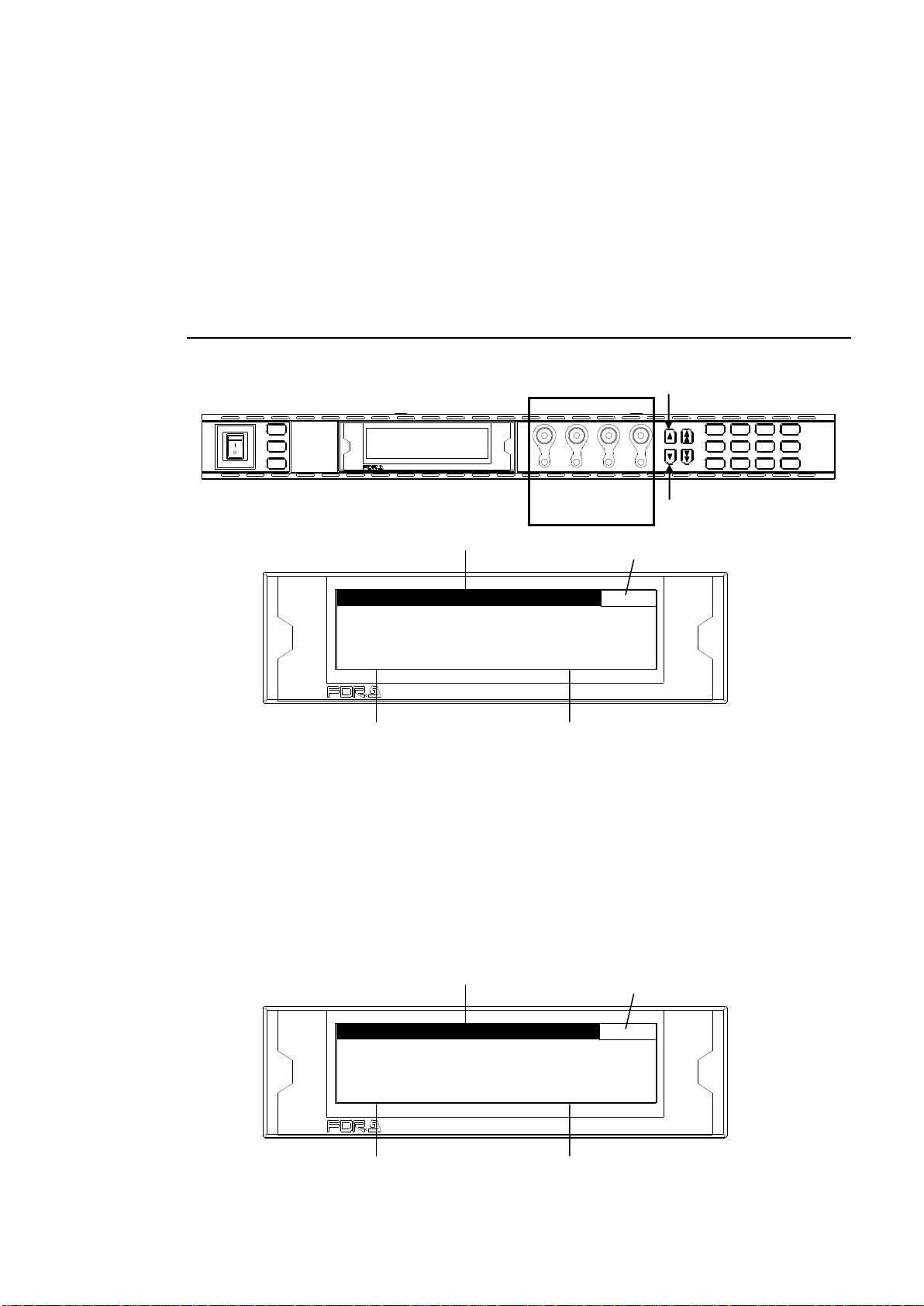
4-2-4. Changing Setting Values
Once the desired menu is displayed, use the controls (F1-F4) to change the setting values.
<NORMAL mode>
In the above example, the PROCESS/SDI AUDIO button has been pressed while the menu
buttons are turned to video menus (lit green) by pressing the VIDEO/AUDIO, so that the
VIDEO PROC AMP menu is displayed.
(If the LEDs around control F1 through 4 knobs are lit, the setting value corresponding to the
lit control knob can be changed.)
If you want to change the VIDEO LEVEL setting value, turn F1. To change the CHROMA
LEVEL setting value, turn F2. For SETUP/BLACK, turn F3, and for HUE turn F4. To go to
other menus assigned to the menu button, press the single-arrow down button. To return to
the previous menu, press the single-arrow up button.
19
Page 20
F1
F2
F3
F4
UNITY UNITY UNITY U NITY
Press the UNITY button to
reset the value. The indicator
lights up orange.
<LIVE SAFE mode>
Menus that do not request a setting change confirmation (such as VIDEO PROC AMP) are
used the same as in NORMAL mode.
Menus that request a setting change confirmation (such as VIDEO INPUT SET) will be in the
setting change confirming state when the parameter is changed.
In the above example, pressing the IN SEL/DOWNMIX button while the button is in VIDEO
menu selection mode (lit green) will display the VIDEO INPUT SET menu. To change the IN
SEL setting, turn F1. Turn F2 for the LOSS setting, and F3 for the BACK COLOR setting. If
any setting is changed, single-arrow buttons and the control knob for the setting that has
changed will blink indicating the setting change confirming state. Pressing the single down
arrow button confirms the change and LEDs stop blinking, then light. Pressing the single up
arrow button cancels the change, the setting returns to before the change, and LEDs stop
blinking, then light.
While the FA-9520 is in a setting change confirming state, all buttons except single-arrow
buttons, control knobs F1 to F4 and their Unity buttons are disabled. To go to other menus,
press either single-arrow button to complete the confirmation.
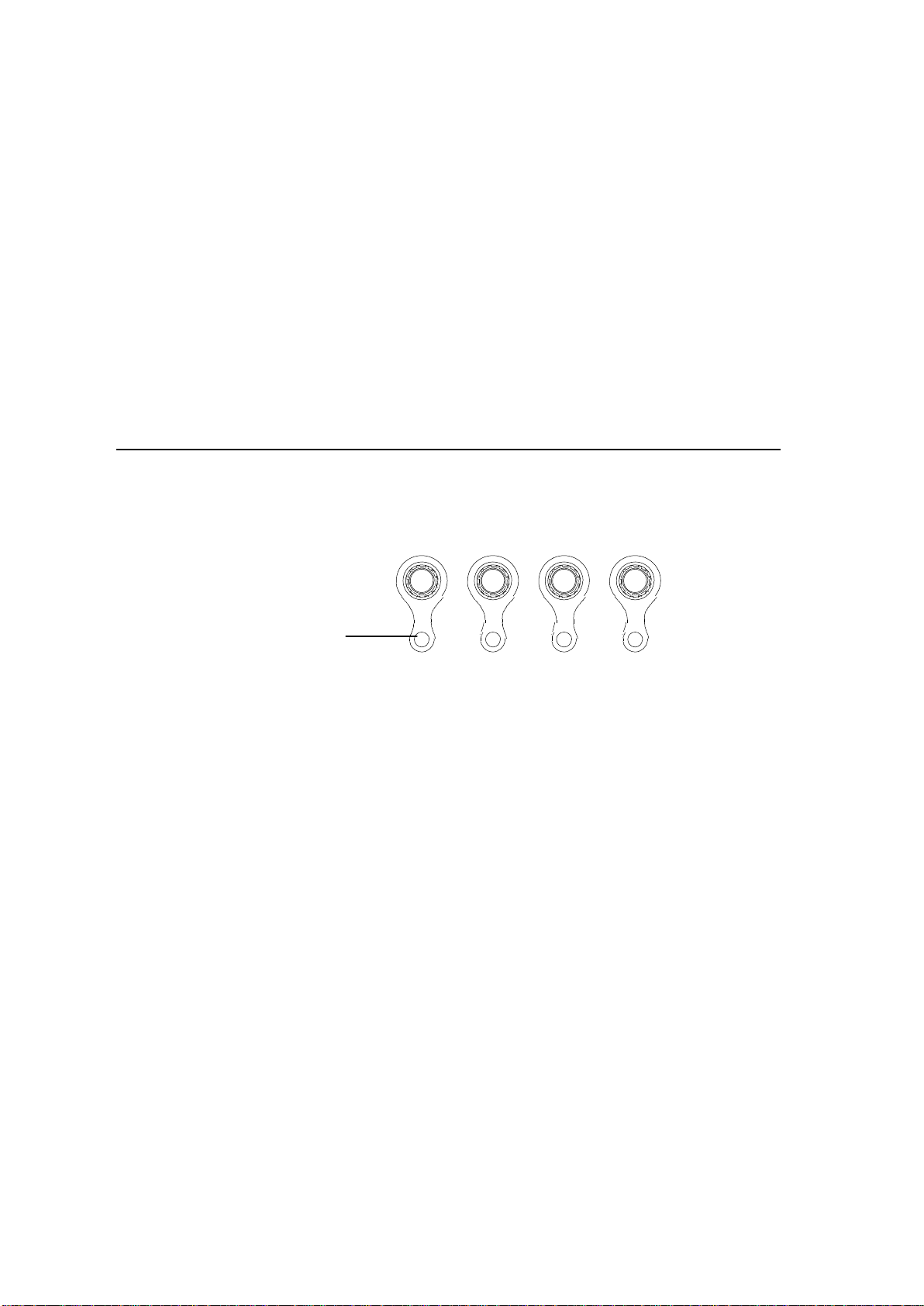
4-2-5. Resetting to Default
<NORMAL mode>
The UNITY indicator light goes off when the setting value is changed from the default value.
Pressing the UNITY button while the light is off returns the corresponding setting value to the
default value. Then the light goes off. Pressing the button again returns the value to the
previous value before resetting to the default value.
<LIVE SAFE mode>
The UNITY indicator light goes off when the setting value has changed from default. Pressing
the UNITY button while the light is off returns the corresponding setting value to default, and
single-arrow buttons and the LED around the control knob above the UNITY button blink in
the setting change confirming state. Pressing the single down arrow button will resets the
value to default, and the UNITY indicator light turns on. Pressing the single up arrow button
cancels the reset, the setting returns to the value before it was reset, and the UNITY indicator
light goes off.
20
Page 21
NOTE
See section 5. “Establishing Connection with the FA-9500/FA-9520” for details on the
connection procedure.
F S S E L E C T
800
M O D E : F S 1
L I N K : D I S ABLE
Parameter
Default
Setting range
Description
MODE
FS1
FS1
FS2
Allows you to select which FS1 or FS2 settings to
change for FS1/FS2-selectable menus.
* FS1/FS2-selectable menus are shown in
section 4-2-2. “Menu Buttons” in the FA-9520
(FA-9520 Mode) Operation Manual.
The selected FS1 or FS2 will be displayed in
place of the menu page for 3 seconds after an
FS1/FS2 selection change.
LINK
DISABLE
DISABLE
ENABLE
DISABLE: Allows you to separately change FS1
and FS2 settings.
ENABLE: Allows you to simultaneously change
the same amount of setting values for FS1 and
FS2 by turning the control knob.
NOTE
Pressing the MU SELECT button while opening the FS SELECT menu allows you to
return to the previous menu before the FS SELECT menu was opened.
F S S E L E C T
800
M O D E : U N A D J U S T A B L E
F S 2 C H O S E N
F S 1 : L O C K
F S 2 : U N L O C K
IMPORTANT
When LINK is set to ENABLE in the FA-95RU, the connected FA-9520 will also be in
LINK mode, and FA-95RU units that are connected to the FA-9520 will also be in LINK
mode.
LINK cannot be set to ENABLE under the following conditions:
1. Either FS1 or FS2 is set to LOCK.
(See section 4-2-7. “Operation Lock Function (FA-9520)” for details.)
2. Either FS1 or FS2 Color Corrector mode is set to Sepia.
(See section 5-2-4. “COLOR CORRECT (C.C.) in the FA-9520 Operaion Manual for
details.)
3. AVO mode is not OFF.
(See section 5-4-1. AVO SETTING” in the FA-9520 Operation Manual for details.)
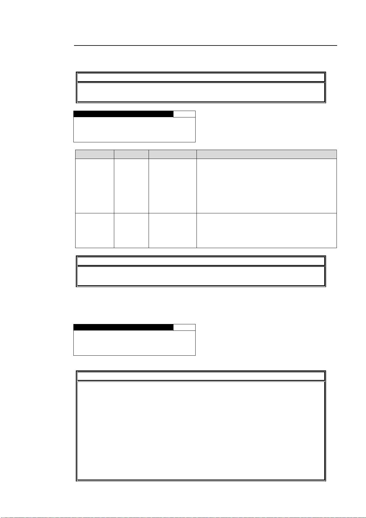
4-2-6. Selecting 2-Channel Frame Synchronizers (FA-9520)
After establishing a connection with an FA-9520, press the MU SELECT button next to the
power switch to open the FS SELECT menu as shown below.
If either FS1 or FS2 operation is locked, MODE and LINK settings are disabled, and the
menu display appears as shown below. See section 4-2-7. “Operation Lock Function
(FA-9520)” for details.
21
Page 22
F S S E L E C T
800
M O D E : F S 1
L I N K : D I S A B L E
V I D E O P R O C A M P
1
VIDEO L E V E L : 1 0 0 . 0 %
C H R O M A L E V E L : 1 0 0 . 0 %
S E T U P / B L A C K : 0 . 0 %
HUE : 0 . 0 °
F S S E L E C T
800
M O D E : F S 2
L I N K : D I S A B L E
V I D E O P R O C A M P
1
V I D E O L E V E L : 1 00.0%
C H R O M A L E V E L : 1 0 0 . 0 %
S E T U P / B L A C K : 0 . 0 %
HUE : 0 . 0 °
F S S E L E C T
800
M O D E : F S 1
L I N K : E N A B L E
V I D E O P R O C A M P
FS1
V I D E O L E V E L : 1 0 0 . 0 %
C H R O M A L E V E L : 1 0 0 . 0 %
S E T U P / B L A C K : 0 . 0 %
HUE : 0 . 0 °
Menu button
PROCESS
SDI AUDIO
Menu button
PROCESS
SDI AUDIO
Menu button
PROCESS
SDI AUDIO
MU
SELECT
MU
SELECT
MU
SELECT
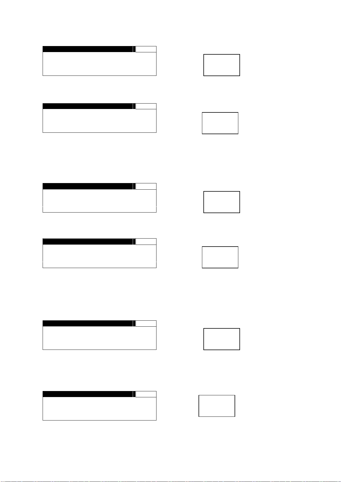
Example 1: Setting VIDEO PROCESS AMP for FS1
1. Press the MU SELECT button next to the power switch to open the FS SELECT menu.
2. Set MODE to FS1, and LINK to DISABLE.
3. Press the PROCESS/SDI AUDIO button to open the VIDEO PROCESS AMP menu.
Press the FS1/LOCK button for it to light green.
4. Turn F1 to F4 control knobs to change FS1 settings.
Example 2: Setting VIDEO PROCESS AMP for FS2
1. Press the MU SELECT button next to the power switch to open the FS SELECT menu.
2. Set MODE to FS2, and LINK to DISABLE.
3. Press the PROCESS/SDI AUDIO button to open the VIDEO PROCESS AMP menu. (If
the VIDEO PROCESS AMP menu was open before opening the FS SELECT menu,
pressing the MU SELECT button returns to the VIDEO PROCESS AMP menu.)
4. Turn control knobs F1 to F4 to change FS2 settings.
Example 3: Setting VIDEO PROCESS AMP for FS1 and FS2 simultaneously
1. Press the MU SELECT button next to the power switch to open the FS SELECT menu.
2. Set MODE to FS1, and LINK to ENABLE.
(If LINK cannot be set to ENABLE, refer to section 4-2-6. “Selecting 2-Channel Frame
Synchronizers (FA-9520)”.)
3. Press the PROCESS/SDI AUDIO button to open the VIDEO PROCESS AMP menu.
4. Turn control knobs F1 to F4 to change setting values. The same amount of setting values
are changed for FS1 and FS2 simultaneously.
22
Page 23
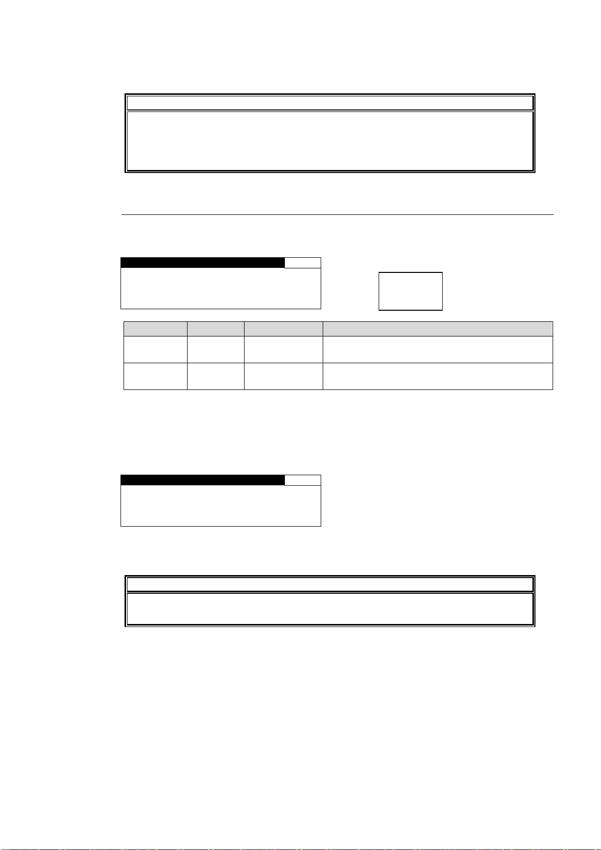
NOTE
In FS1/FS2 simultaneous setting mode, each control knob applies identical
adjustment values to both FS1 and FS2.
Menus supported for simultaneous setting mode are shown with “⊚” in the menu list in
section 4-2-2. “Menu Buttons” in the FA-9520 Operation Manual.
F R O N T L O C K
804
F S 1 : U N L O C K
FS2: U N L O C K
P R E S S F 3 U N I T Y
T O L O C K F R O N T
Parameter
Default
Setting range
Description
FS1
UNLOCK
UNLOCK
LOCK
UNLOCK: FS1 settings can be changed.
LOCK: FS1 settings are disabled.
FS2
UNLOCK
UNLOCK
LOCK
UNLOCK: FS2 settings can be changed.
LOCK: FS2 settings are disabled.
F R O N T L O C K
804
F S 1 : L O C K
F S 2 : L O C K
T O U N L O C K F R O N T ,
H O L D D O W N L O C K S W
IMPORTANT
If either FS1 or FS2 is set to LOCK, the LINK setting under FS SELECT menu will be
automatically set to DISABLE.
LOCK
5. To exit simultaneous setting mode, press the MU SELECT button, then set LINK to
DISABLE.
4-2-7. Operation Lock Function (FA-9520)
FA-95RU front panel button operation can be disabled for all or either FS1 or FS2 operation.
The LOCK button allows you to set the operation lock function.
Complete settings for FS1 and FS2, then press the F3 Unity button for the settings to take
effect.
The LOCK button lights green if either FS1 or FS2 is set to LOCK.
The LOCK button lights orange if both FS1 and FS2 are set to LOCK. In this case, all buttons
on the front panel are disabled except the LOCK button.
Press and hold down the LOCK button for at least 3 seconds while it is lit orange to unlock
front panel buttons.
23
Page 24
U N I T I D S E L
801
MU ID: 1
I P : 1 9 2 . 1 6 8 . 0 . 1 0
N A M E : N o N a m e
F 3 : S E T F 4 : C A N C E L
I P A D D R S E L
802
I P : 1 9 2 . 1 6 8 . 0 . 1 0
NAME:FA- 952 0
F 3 U N I T Y S E T
F 4 U N I T Y C A N C E L
MU
SELECT
MU
SELECT
5. Establishing Connection with the FA-9500/FA-9520
FA-95RU can control the FA-9500/FA-9520 when a connection is established.
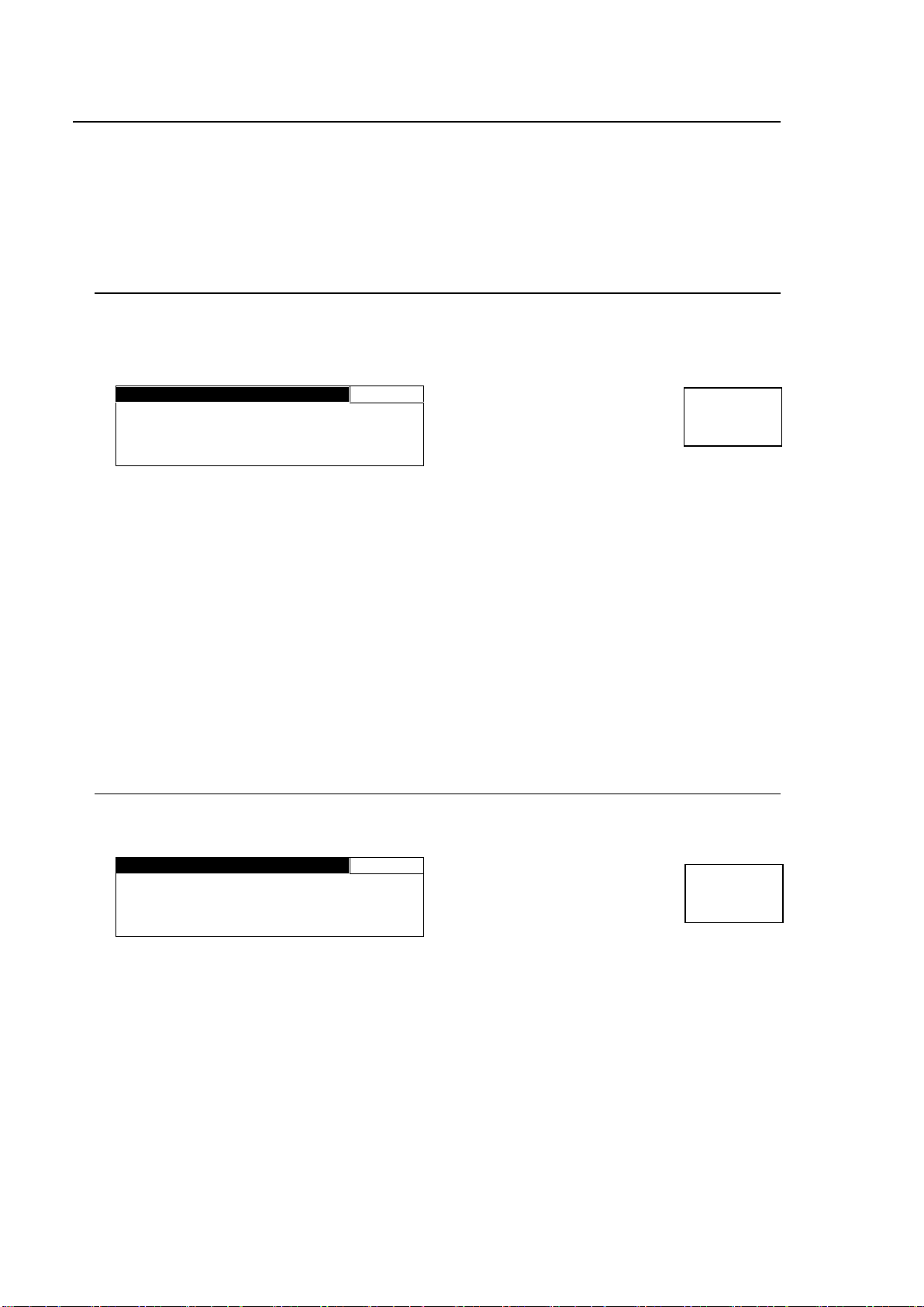
There are two ways to connect to the FA-9500/FA-9520; one is in Unit ID Selection mode, which
allows you to connect an FA-9500/FA-9520 by selecting an ID from among 100 ID numbers, and
the other is in IP Address Selection mode, which allows you to connect an FA-9500/FA-9520 by
specifying an IP address.
5-1. Unit ID Selection Mode
Pressing the MU SEL button opens the UNIT ID SEL menu.
(If the FA-95RU is connected to an FA-9520, the FS SELECT menu will be displayed. Press the
single down-arrow button to open the UNIT ID SEL menu.)
Turn F1 and select the FA-9500/FA-9520 to be connected from MU IDs 1 through 100.
The IP address and unit name will be displayed for each MU ID. (See section 8-4. “Unit ID
Assignment” for details on IP address and unit name settings.)
Press the UNITY button under F3 (SET) to establish a connection with the selected
FA-9500/FA-9520 using F1.
The CONNECT STATE menu (5-3 ) appears when connection is initiated.
To cancel the selection, press the UNITY button under F4 (CANCEL). Cancelling the connection
returns the settings to their last state before change.
Select DISCONNECT by F1 and press the UNITY button under F3 to disable the connection of
FA-95RU to any FA-9500/FA-9520. (The connected FA-9500/FA-9520 will also be
disconnected.)
“MU ID: IP ADDR SEL” indicates the FA-9500/FA-9520 is connected via IP Address Selection
mode (5-2. IP Address Selection Mode).
5-2. IP Address Selection Mode
Press the MU SELECT button. The UNIT ID SEL menu appears. Then, press the single
down-arrow button. The IP ADDR SEL menu appears.
Enter the IP address of the FA-9500/FA-9520 to be connected using control knobs F1 to F4.
(If the IP address assigned as in section 8-4. “Unit ID Assignment” is selected, the assigned unit
name will be displayed under NAME.)
Press the UNITY button under F3 to establish connection with the FA-9500/FA-9520 of the
selected IP address. The CONNECT STATE menu (5-3) will then appear. To cancel the
selection, press the UNITY button under F4 (CANCEL). Cancelling the connection returns the
settings to their last state before change.
The MU ID name will be displayed under NAME if there is a name assigned to the IP address.
24
Page 25
C O N N E C T S T A T E
803
I P : 1 9 2 . 1 6 8 . 0 . 1 0
S T A T E : C O N N E C T E D
ID:FA- 9 5 0 0
MU:FA- 9 5 0 0
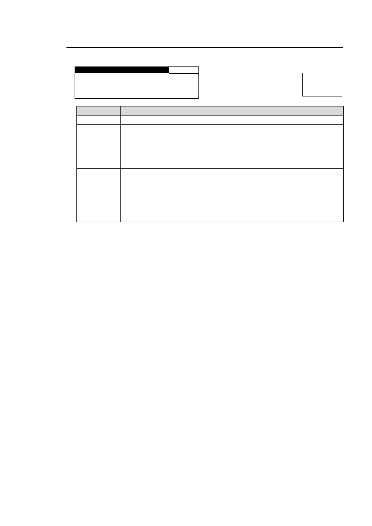
Item
Description
IP
Shows the IP address of the connected FA-9500/FA-9520.
STATE
DISCONNECT: Connection is disabled.
CONNECTED: The FA-9500/FA-9520 of the selected IP address is connected.
NO CONNECTION: Connection with the selected FA-9500/FA-9520 could not
be established.
OVERLIMIT: A maximum 5 FA-9500/FA-9520 units are already connected. No
more units can be connected.
ID
Shows the unit name assigned in Unit ID Assignment (section 8-4).
NO NAME is indicated if a unit name is not assigned.
MU
Shows the unit name assigned by and in the FA-9500/FA-9520 itself.
*1
“MU IS LOCAL MODE” indicates that the connected FA-9500/FA-9520 is set to
LOCAL MODE.
The FA-95RU cannot control the FA-9500/FA-9520 that is set to LOCAL mode.
To enable control, set the FA-9500/FA-9520 to REMOTE mode.
*2
Menu button
MU
SELECT
5-3. CONNECT STATE
Connections with FA-9500/FA-9520 units can be checked in the CONNECT STATE menu.
*1 See “Utility Settings” [Set Event Name] in the FA-9500/FA-9520 Operation Manual for
details on name assignments.
*2 See “CONTROL SETTING” in the FA-9500/FA-9520 Operation Manual for details on
LOCAL/REMOTE settings.
25
Page 26
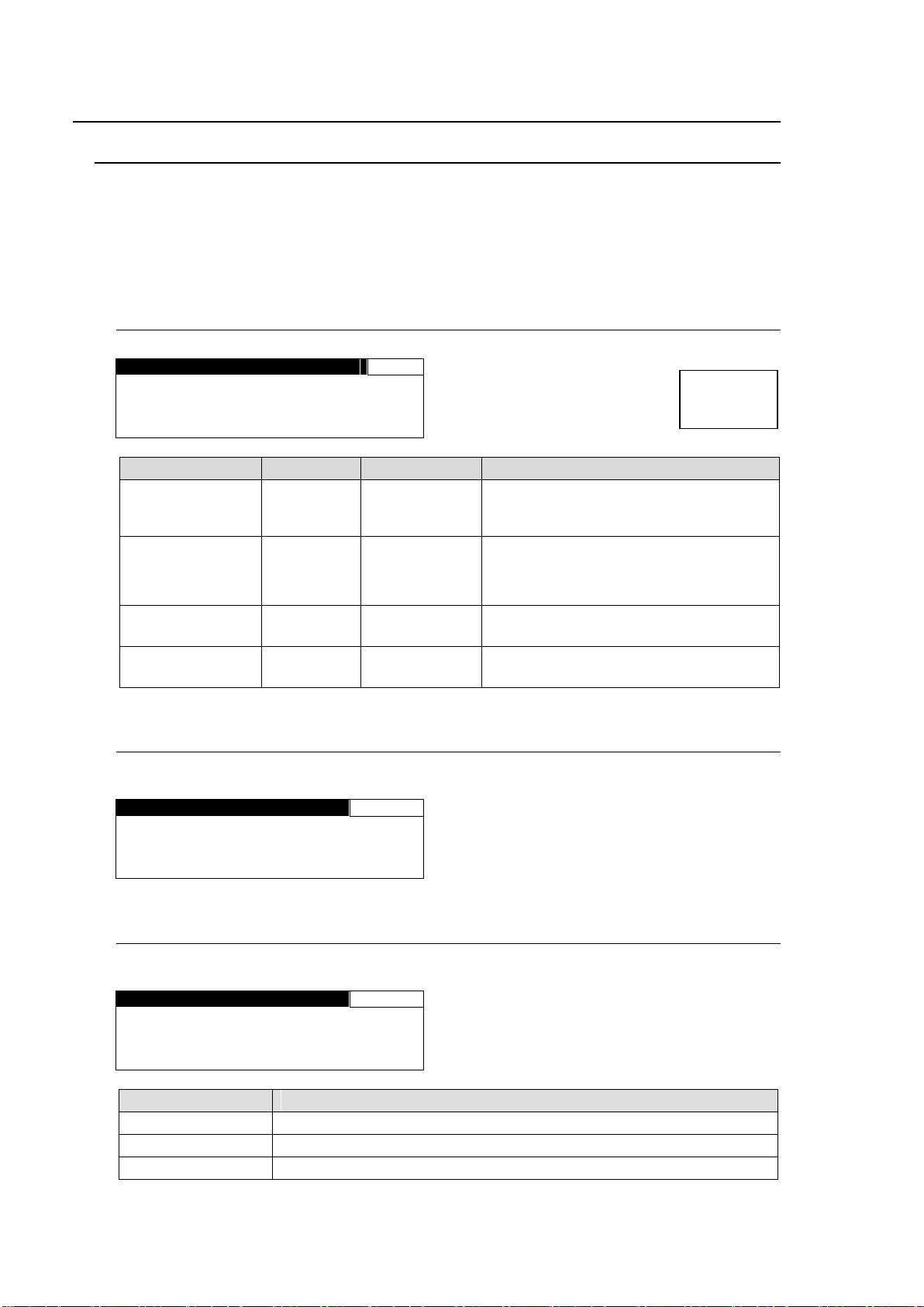
F R O N T P A N E L S E T
815
V F D B R I G H T : 5 0
V F D A U T O O F F : D I S A B L E
L E D B R I G H T : L E V E L 4
B U Z Z E R : E N A B L E
Parameter
Default
Setting range
Description
VFD BRIGHT
50
10 - 50
Selects the brightness of the front display
panel.
10 - 50: Dark to bright
VFD AUTO OFF
DISABLE
DISABLE
5 min
10 min
30 min
Selects a length of non-operating time
until VFD goes off.
DISABLE: VFD will not go off.
LED BRIGHT
LEVEL4
LEVEL1 - 8
Selects the brightness of the front LED.
LEVEL 1 – 8: Dark to bright
BUZZER
ENABLE
DISABLE
ENABLE
DISABLE: Disable the buzzer function
ENABLE: Enable the buzzer function
FA- 9 5 R U I N F O
825
F P G A : 0 1 . 0 0
S O F T : 0 1 . 0 0
FAN : NORMAL
R U N E T W O R K I N F O
826
I P : 1 9 2 . 1 6 8 . 0 . 1 0 0
S U B : 2 5 5 . 2 5 5 . 2 5 5 . 0
G W : 0 . 0 . 0 . 0
Parameter
Description
IP
Shows the FA-95RU IP address settings.
SUB
Shows the FA-95RU subnet mask settings.
GW
Shows the FA-95RU gateway settings.
Menu button
MU
SELECT
6. Changing and Viewing FA-95RU Settings
6-1. MU SELECT Button Menus
Hold down the MU SELECT button to open menus for changing front panel settings and viewing
version information as shown below. (Press the MU SELECT button again to return to the
previous state.) While the front panel setting menus (6-1-1 FRONT PANEL SET to 6-1-3
FA-95RU NET WORK INFO) are enabled, all front panel buttons except LOCK and arrow
buttons are disabled. To enable the buttons, press the MU SELECT button again.
6-1-1. FRONT PANEL SET
6-1-2. FA-95RU INFO
Shows the FA-95RU version information and the state of cooling fans.
6-1-3. FA-95RU NET WORK INFO
Shows the FA-95RU network settings.
See section 8-2. Network Settings for detail on the FA-95RU network settings.
26
Page 27
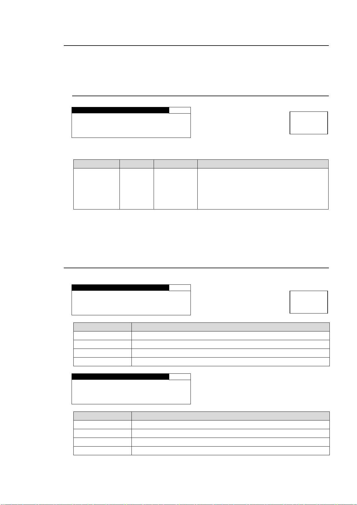
F R O N T O P E R A T I O N
294
M O D E : N O R M A L
Parameter
Default
Setting range
Description
MODE
NORMAL
NORMAL
LIVE SAFE
Allows you to select a front panel operation
mode for the FA-95RU.
NORMAL: Changes made by control knobs F1
to F4 will be applied immediately to the unit.
LIVE SAFE: Requires confirmation before
control knob changes are applied. *
* Whenever a change is made by control knobs F1 to F4, the single-arrow buttons (up and
down) and the LED around the control knob of the changed parameter blink confirming the
change. Pressing the single down arrow button confirms the change and the control knob
LED lights. Pressing the single up arrow button cancels the change and everything reverts to
the previous state. Refer to section 4. “Front Panel Operations” for details.
FA- 950 0 V e r .
2 98
F P G A 1 : 0 1 . 0 0
F P G A 2 : 0 1 . 0 0
F P G A 3 : 0 1 . 0 0
S O F T : 0 1 . 0 0
Parameter
Description
FPGA1
Shows the FPGA1 version.
FPGA2
Shows the FPGA2 version.
FPGA3
Shows the FPGA3 version.
SOFT
Shows the software version of the FA-9500/FA-9520(in FA-9500 mode).
FA- 9 5 2 0 V e r .
298
F P G A 1 : 0 1 . 0 0
F P G A 2 : 0 1 . 0 0
F P G A 3 : 0 1 . 0 0
S O F T : 0 1 . 0 0
Parameter
Description
FPGA1
Shows the FPGA1 version.
FPGA2
Shows the FPGA2 version.
FPGA3
Shows the FPGA3 version.
SOFT
Shows the software version of the FA-9520 (in FA-9520 mode).
Menu button
STATUS
OTHER
Menu button
STATUS
OTHER
6-2. Other Settings & Information (STATUS/OTHER)
Menus that can be accessed from Menu buttons in the FA-95RU are common with
FA-9500/FA-9520 except following menus that can be accessed using the STATUS/OTHER
menu button and arrow buttons.
6-2-1. FRONT OPERATION
* Menu page number is 294 when an FA-9520 (in FA-9520 mode) is connected. It changes
to 196 when an FA-9500 or FA-9520 (in FA-9500) mode is connected.
6-3. FA-9500 / FA-9520 Ver.
Displays the version information on the connected FA-9500/FA -9520.
27
Page 28
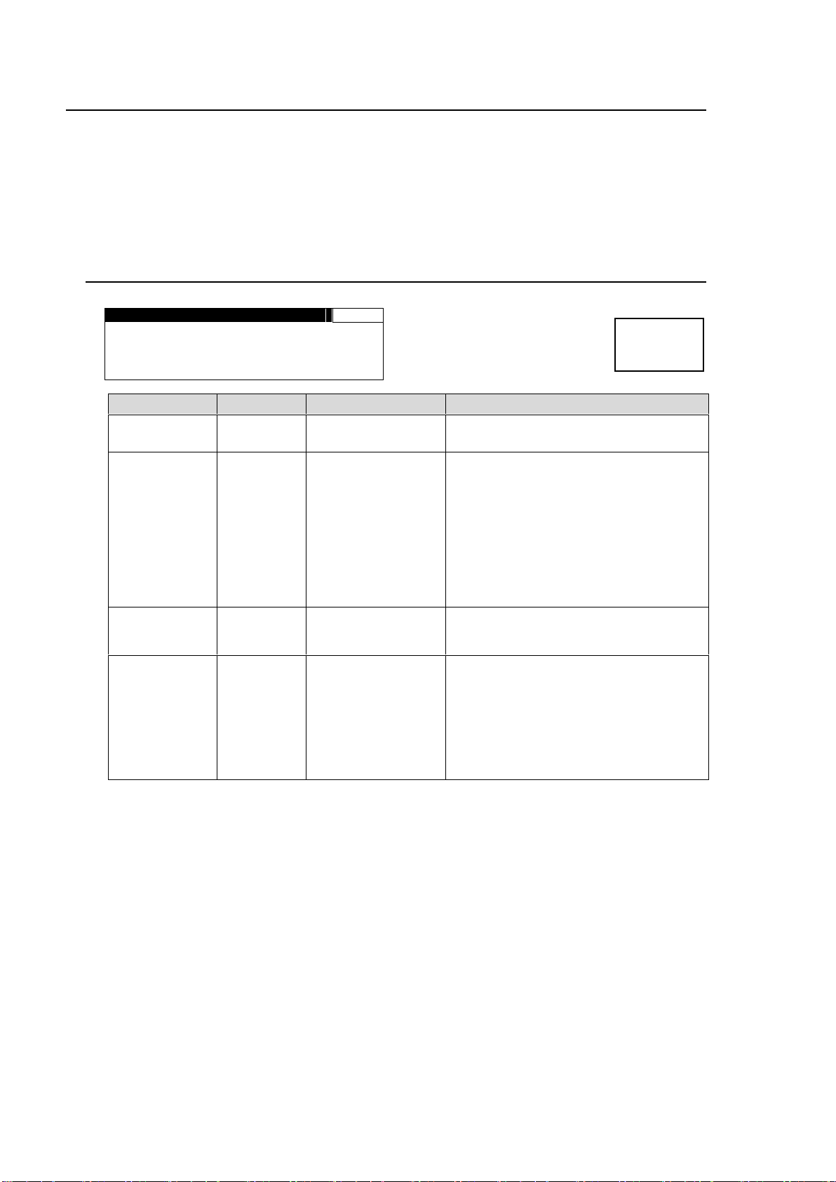
E V E N T L O A D
191
NO. : D E F A U L T
M O D E : L O A D A L L
L O A D S T A R T F 3 U N I T Y
UNIT:FA- 95RU
Parameter
Default
Setting range
Description
NO.
DEFAULT
*1
EVENT 1 – 100
*2
Allows you to select the number of an
event you want to load.
MODE *3
LOAD ALL
LOAD ALL
LOAD FS1 ONLY *4
LOAD FS2 ONLY *4
Allows you to select an event loading
mode.
LOAD ALL: Allows you to load all
settings stored in the selected event.
LOAD FS1 ONLY: Allows you to load
FS1 settings stored in the selected
event.
LOAD FS2 ONLY: Allows you to load
FS2 settings stored in the selected
event.
LOAD START
F3 UNITY
-
-
Loads the event that is selected under
NO. when the F3 UNITY button is
pressed.
UNIT
FA-95RU
FA-95RU
FA-9500
FA-9520
Allows you to select whether to recall an
event stored in the FA-95RU, FA-9500
or FA-9520.
FA-95RU: Allows you to recall an event
stored in the FA-95RU.
FA-9500/FA-9520: Allows you to recall
an event stored in the FA-9500 or
FA-9520.
Menu button
EVENT
7. Event Memory
The FA-95RU can store and recall 100 event memories for an FA-9500/FA-9520 (in FA-9500
mode) and FA-9520 (in FA-9520 mode) respectively. It can also control event memories in the
connected FA-9500/FA9520.
Every press of the EVENT button alternates the menus: EVENT LOAD (lit green), EVENT SAVE (lit
red), and EVENT SETUP(lit orange). To go to the desired page, press the EVENT button a few
times, or press the EVENT button once and the up or down single arrow button to move between
EVENT pages.
7-1. EVENT LOAD
*1 DEFAULT recalls the default settings.
*2 If FA-95RU is selected under UNIT, event names can be set for events 1 through 100 via
the web browser. See section 8-5. “Event Naming“ for details. The defaul event names
are EVENT 1 through EVENT 100.
If FA-9500 is selected under UNIT, event names set in the FA-9500 or FA-9520 in
FA-9500 mode will be displayed. See the FA-9500 or FA-9520 (FA-9500 Mode) Operation
Manual for details.
If FA-9520 is selected under UNIT, event names set in the FA-9520 in FA-9520 mode will
be displayed. See the FA-9520 (FA-9520 Mode) Operation Manual for details.
*3 MODE will be displayed if an FA-9520 in FA-9520 mode is connected.
*4 Only the FS1 or FS2 settings that are shown with or ⊚ in the menu list in section “Menu
Buttons“ in the FA-9500/FA9520 Operation Manual, and can be respectively set for FS1
and FS2. Other settings will always be loaded regardless of the selected loading mode.
28
Page 29
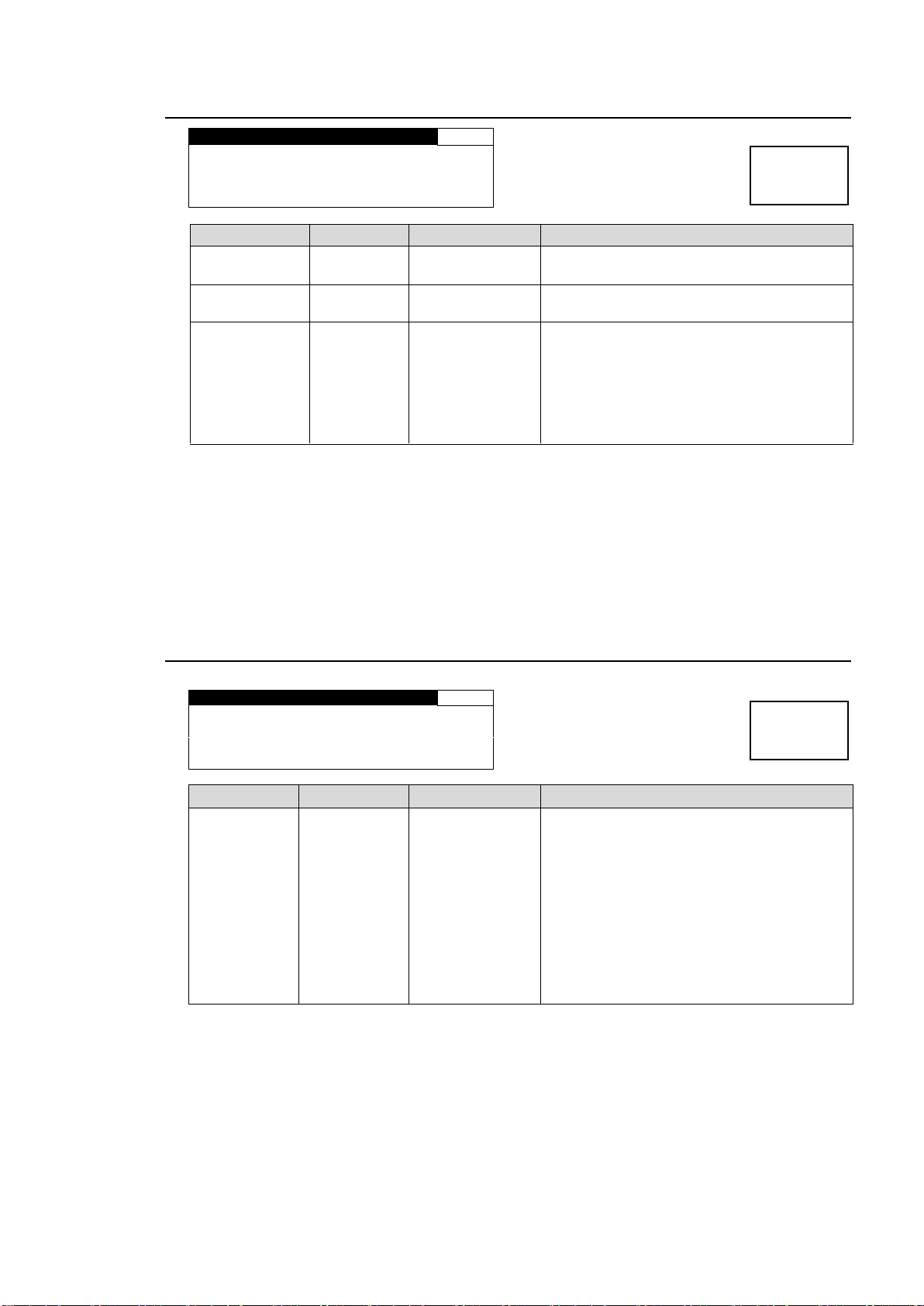
E V E N T S A V E
192
NO.:E V E N T 1
L O A D S T A R T F 2 U N I T Y
UNIT:FA- 95RU
Parameter
Default
Setting range
Description
NO.
EVENT 1
EVENT1 - 100
*1
Allows you to select the number of an event
you want to save.
SAVE START
F2 UNITY
-
-
Saves the event that is selected under NO.
when the F2 UNITY button is pressed.
UNIT
FA-95RU
FA-95RU
FA-9500
FA-9520
Allows you to select the unit to save the
event to.
FA-95RU: Allows you to save the event to
the FA-95RU event memory.
FA-9500/FA-9520: Allows you to save the
event to the FA-9500/FA-9520 event
memory.
E V E N T S E T U P
193
S T A R T : L A S T S E T T I N G
Parameter
Default
Setting range
Description
START
LAST
SETTING
LAST SETTING
VIDEO
FORMAT
DEFAULT
EVENT1 -
EVENT100
*1
Selects an event you want to load at
startup.
LAST SETTING: Loads the last settings
that are used before startup.
VIDEO FORMAT: Loads the settings that
are stored in event memory for the last
format that is detected before startup.
DEFAULT: Resets all settings to the default
settings at startup.
EVENT1 - 100: Loads the selected event
memory among event memory settings 1
through 100.
Menu button
EVENT
Menu button
EVENT
7-2. EVENT SAVE
*1 If FA-95RU is selected under UNIT, event names can be set for events 1 through 100 via
the web browser. See section 8-5. “Event Naming“ for details. The defaul event names
are EVENT 1 through EVENT 100.
If FA-9500 is selected under UNIT, event names set in the FA-9500 or FA-9520 in
FA-9500 mode will be displayed. See the FA-9500 or FA-9520 (FA-9500 Mode) Operation
Manual for details.
If FA-9520 is selected under UNIT, event names set in the FA-9520 in FA-9520 mode will
be displayed. See the FA-9520 (FA-9520 Mode) Operation Manual for details.
7-3. EVENT SETUP
*1 Recalls the events stored in the connected FA-9500/FA-9520.
29
Page 30

7-4. Parameters That Are Not Stored in Event Memories
The following parameters are not stored in event memories for FA-9500/FA-9520 (FA9500
mode).
DISABLE/ENABLE settings of CHANGEOVER in the VIDEO INPUT SET menu.
ON/OFF settings of FREEZE in the FREEZE SETmenu.
ON/OFF settings of MASTER MUTE in the MASTER OUT GAIN Setting (MASTER) menu.
All settings in the EVENT SETUP menu (7-3).
All settings in the Other Settings & Information (OTHER) menu.
All settings in the Various Signal Status Display (STATUS) menu.
Unit Name settings in the Event Control menu.
All settings under Network Settings.
All settings in the Establishing Connection with the FA-9500/FA-9520 menu (5).
All settings in the LOUDNESS MEASUREMENT menu.
ON/OFF settings of CONTROL in the LOUDNESS CONTROL ENABLE menu.
All settings in the WEB Browser Settings menu (8).
The following parameters are not stored in event memories for FA-9520 (FA9520 mode).
ON/OFF settings of FREEZE in the FREEZE SETmenu.
All settings in the EVENT SETUP menu (7-3).
All settings in the Other Settings & Information (OTHER) menu.
All settings in the Various Signal Status Display (STATUS) menu.
All settings under Network Settings.
All settings in the LOUDNESS MEASUREMENT menu.
ON/OFF settings of CONTROL in the LOUDNESS CONTROL ENABLE menu.
* Refer to the FA-9500/FA9520 Operation Manual for details on all above settomgs that are not
given section numbers in parentheses.
7-5. Note on Event Memory Operation
Do not power off the unit while saving an event. The event may not be properly stored.
The FA-95RU periodically checks and saves changes.
Wait at least 5 seconds after changing settings before turning the power off. We also
recommend saving important data.
See sections 8-7-1 “ Configuration Data Backup”, and 8-7-2 “Event Data Backup
(FA-9500/FA9520)” for details on how to save setting data.
30
Page 31
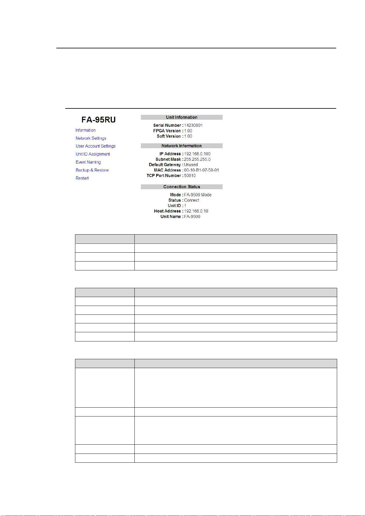
Item
Description
Serial Number
Serial number of FA-95RU
FPGA Version
FPGA version of FA-95RU
Soft Version
Software version of FA-95RU
Item
Description
IP Address
IP address of FA-95RU
Subnet Mask
Subnet mask of FA-95RU
Default Gateway
Gateway of FA-95RU
MAC Address
MAC address of FA-95RU
TCP Port Number
TCP port number FA-95RU
Item
Description
Mode
Shows the selected connection state.
Disconnect: Indicates no FA-9500/FA-9520 is connected
FA-9500: Indicates an FA-9500 is connected.
FA-9520: Indicates an FA-9520 in FA-9520 mode is connected.
FA-9520 (FA-9500 mode): Indicates an FA-9520 in FA-9500 mode is
connected.
Status
Shows the status of connection with FA-9500.
Unit ID
Shows registered ID number if the connected FA-9500’s IP address is
registered using Unit ID Assignment
*1.
Shows the message “IP Address Select” if the connection is established
via the IP ADDR SEL menu *2
Host Address
Shows the IP address of the connected FA-9500.
Unit Name
Shows the unit name of the connected FA-9500.
8. WEB Browser Settings
This section describes FA-95RU settings via a web browser.
See section 3. “Connections” for details on connecting with a computer.
Open a web browser on the connected computer, and enter the address http://192.168.0.100/
(factory default setting) in the address bar. The Information window as shown below appears.
8-1. Information
Unit Information
Network Information
Connection Status
*1 See section 8 “WEB Browser Settings” for details.
*2 See section 5-2 “IP Address Selection Mode” for details.
31
Page 32
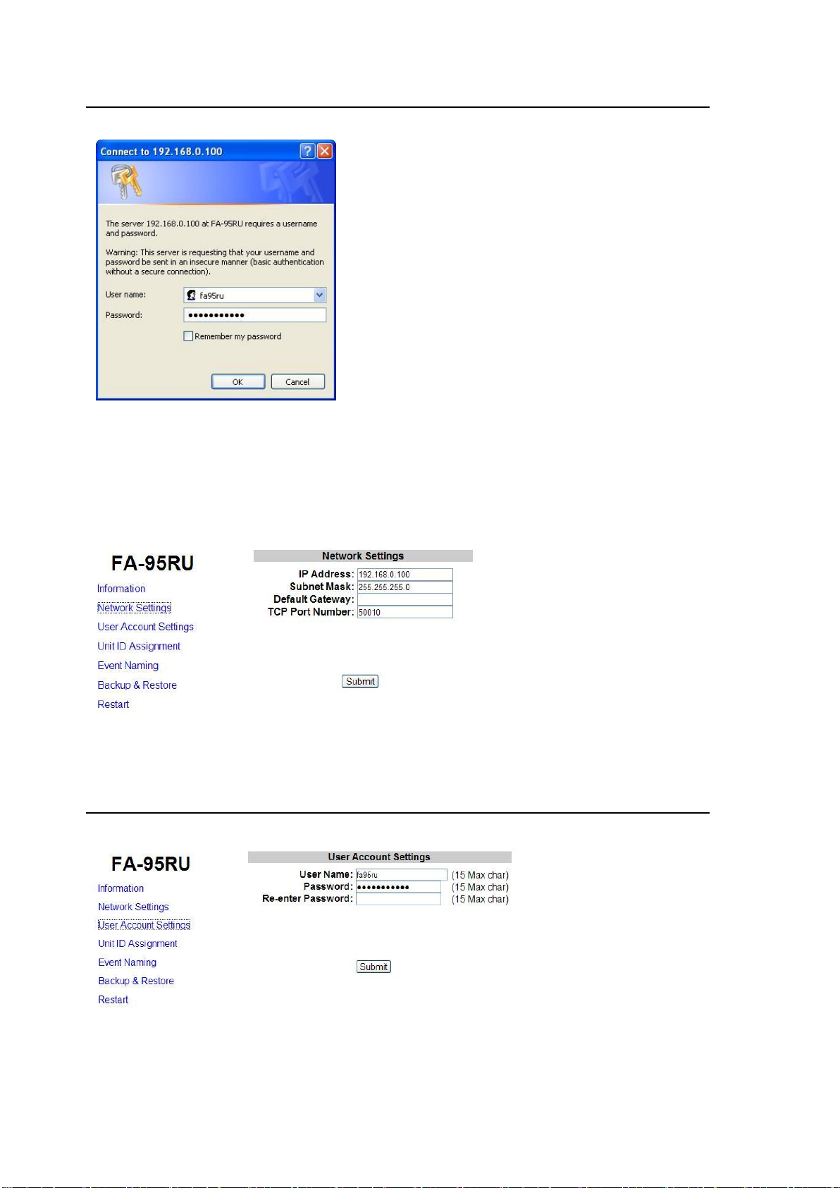
8-2. Network Settings
Click Network Settings. The authentication dialog box appears. (Only the first time)
Press the Enter key on the keyboard to connect to the FA-95RU.
The authentication dialog box appears.
Enter your user name and password.
User name: fa95ru
Password: foranetwork
If the authentication is successful, the Network Settings page as shown below appears.
To change the network address, change the settings and click Submit.
Changes will be applied after rebooting or 8-8 “Restart” is performed.
8-3. User Account Settings
Click User Account to open the page as shown below.
To change the user account, change the settings and click Submit.
The authentication dialog box will not appear if the User Name and Password setting boxes are
left empty.
Changes will be applied after rebooting or 8-8. “Restart” is performed.
32
Page 33
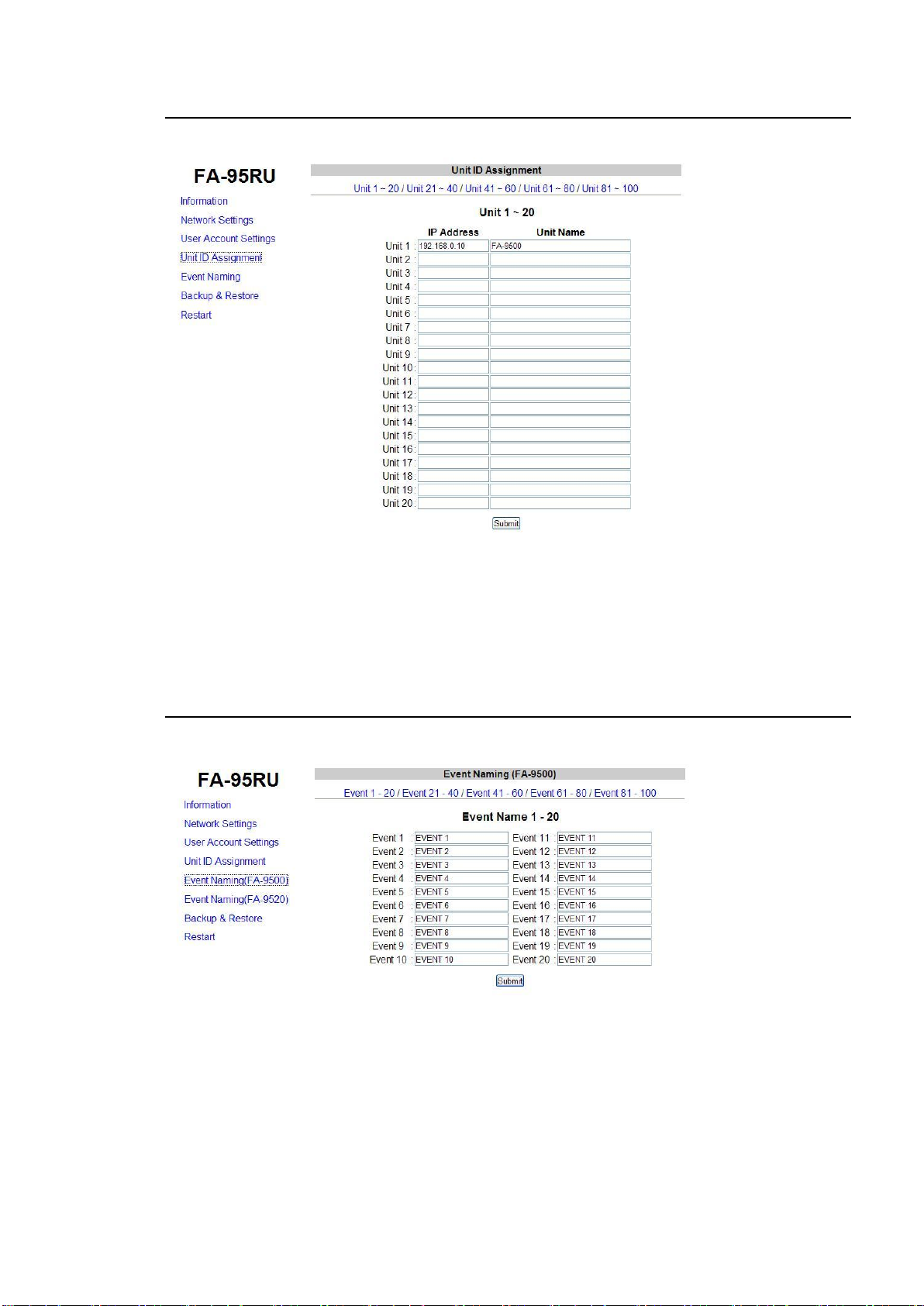
8-4. Unit ID Assignment
Click Unit ID Assignment to open the page as shown below.
This page allows you to assign IP addresses to MU IDs to select units to be connected in Unit ID
selection mode, described in section 5-1. “Unit ID Selection Mode”.
After assigning IP addresses, click Submit. (The assignments are effective without rebooting.)
Unit names can be set with up to 15 alphanumeric characters.
8-5. Event Naming (FA-9500)
Click Event Naming to open the page as shown below.
This page allows you to name the events 1 through 100 of the connected FA-9500 and FA-9520
(FA-9500 mode) that are saved in the FA-95RU.
Twenty events each are shown per page. Change the page to display desired events by clicking
Event 1-20, Event 21-40, Event 41-60, Event 61-80, or Event 81-100.
Enter a name with 15 alphanumeric characters for the desired event number.
Be sure to click Submit after setting the name.
Once the event name is assigned, the assigned name will be displayed for the FA-95RU event
memories selected in the event settings. See section 7. “Event Memory” for details.
The default event names are EVENT 1 through EVENT 100.
33
Page 34
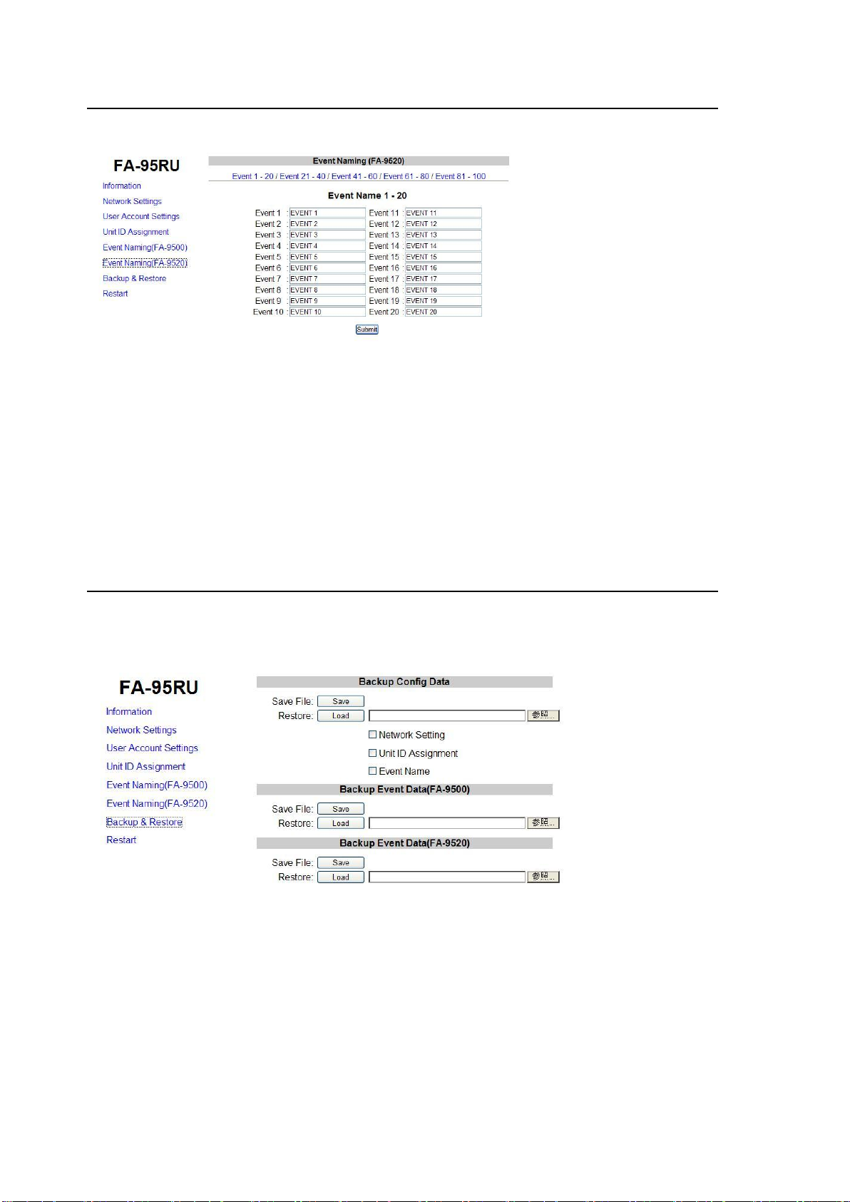
8-6. Event Naming (FA-9520)
Click Event Naming to open the page as shown below.
This page allows you to name the events 1 through 100 of the connected FA-9520 (FA-9520
mode) that are saved in the FA-95RU.
Twenty events each are shown per page. Change the page to display desired events by clicking
Event 1-20, Event 21-40, Event 41-60, Event 61-80, or Event 81-100.
Enter a name with 15 alphanumeric characters for the desired event number.
Be sure to click Submit after setting the name.
Once the event name is assigned, the assigned name will be displayed for the FA-95RU event
memories selected in the event settings. See section 7. “Event Memory” for details.
The default event names are EVENT 1 through EVENT 100.
8-7. Backup & Restore
Click Backup & Restore to open the dialog box as shown below.
This dialog box allows you to save the FA-95RU settings and event data to a PC.
The saved data can be recalled.
34
Page 35
8-7-1. Configuration Data Backup
The FA-95RU configuration data can be saved/recalled to/from a PC as a CSV file.
Saving Configuration Data to a file
Click Save File: Save under “Backup Config Data”.
The File Download confirmation window appears. Click Save.
The directory window opens. Select a location to save the file.
Change the file name if you wish.
Click Save.
When the file download is complete, the window as shown below appears.
The data is backed up.
Click Close.
35
Page 36
IMPORTANT
The FA-95RU uses the CSV file format for the configuration data backup, which
enables commercially available spreadsheet software to edit the data. However, Unit
ID or event names that consist only of numbers may be recognized as numeric values
by such software and appears differently after they are recalled to the FA-95RU. It is
recommended to use alphabetical along with numeric values for names to enable
editing using commercially available spreadsheet software.
Recalling the Saved Configuration Data from a PC
Select items in the configuration data to be recalled.
Checking Network Settings will recall the setting data that is set under the Network Settings
menu in section 8-2.
Checking Unit ID Assignment will recall the setting data that is set under the Unit ID
Assignment menu in section 8-4.
Checking Event Name will recall the setting data that is set under the Event Naming menu in
section 8-5.
Click Browse next to Restore and select a file in which the configuration data is to be saved.
Click Load. The confirmation window as shown below appears.
Click OK to start recalling the data.
Click Cancel to stop the recall.
Checked items such as Network Settings will be applied after restart.
Be sure to perform restart as described in section 8-8 “Restart”.
36
Page 37
8-7-2. Event Data Backup (FA-9500/FA9520)
The event data saved in the FA-95RU can be saved/recalled to/from a PC.
Saving Configuration Data to a file
Click Save File: Save under “Backup Event Data (FA-9500)” or “Backup Event Data
(FA-9520)”.
The File Download confirmation window appears. Click Save.
The directory window opens. Select a location to save the file.
Change the file name if you wish.
Click Save.
When the file download is complete, the window as shown below appears.
The data is saved.
Click Close.
37
Page 38
IMPORTANT
The FA-95RU uses the CSV file format for the configuration data backup, which
enables commercially available spreadsheet software to edit the data. However, Unit
ID or event names that consist only of numbers may be recognized as numeric values
by such software and appears differently after they are recalled to the FA-95RU. It is
recommended to use alphabetical along with numeric values for names to enable
editing using commercially available spreadsheet software.
Recalling the Saved Event Data from a PC
Click Browse next to Restore and select a file in which the configuration data is to be saved.
Click Load. The confirmation window as shown below appears.
Click OK to start recalling the data.
Click Cancel to stop the recall.
8-8. Restart
Click Restart to open the page as shown below.
Be sure to click Restart after changing Network Settings or User Account Settings.
38
Page 39
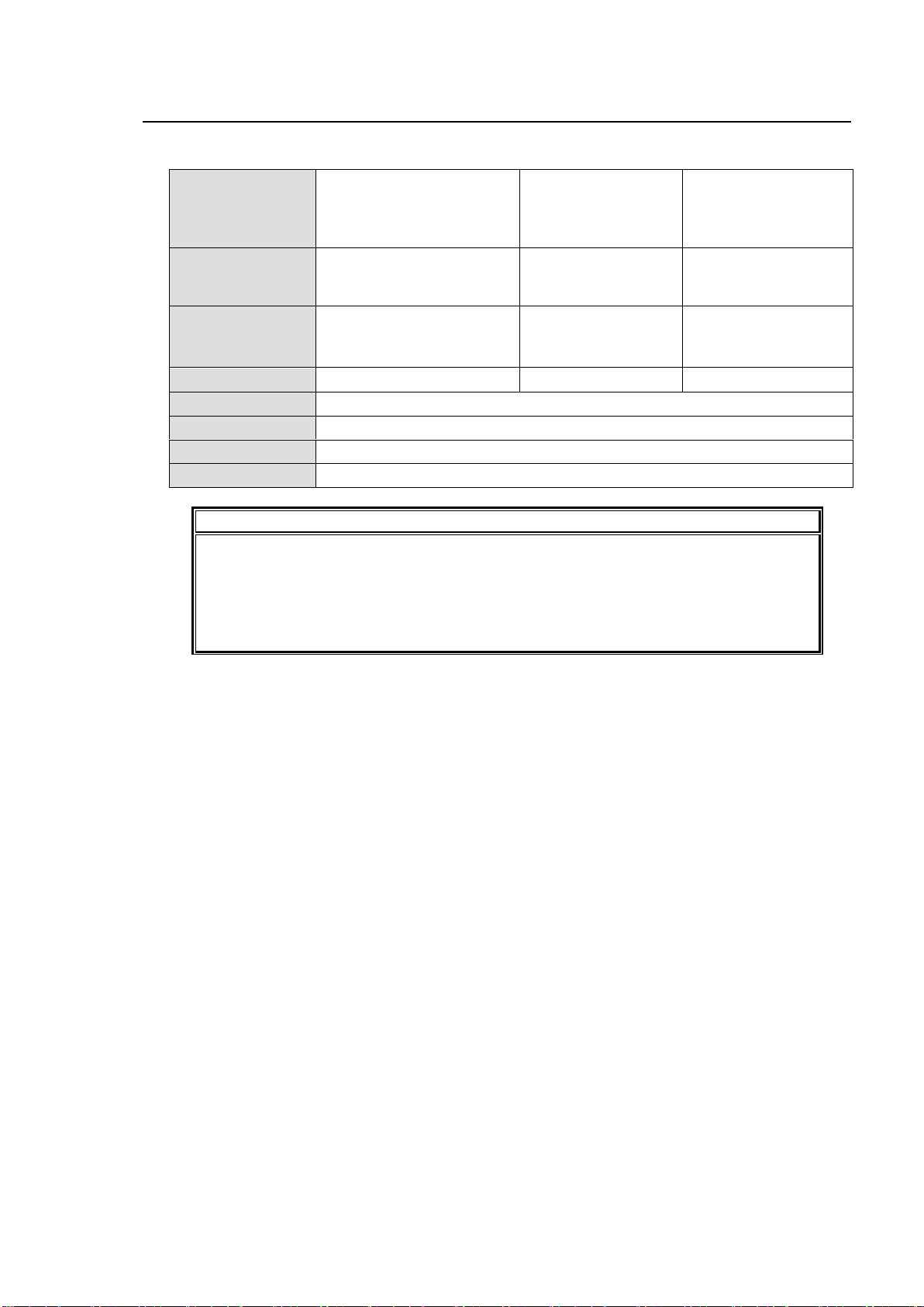
OS
Windows® XP operating
system SP2 or later
Professional (32bit)
Windows Vista®
operating system
Business (32bit)
Windows® 7
operating system
Professional
(32bit/64bit)
Browser
Windows® Internet
Explorer 8,
Firefox®21.0
Windows® Internet
Explorer 8,
Firefox®21.0
Windows® Internet
Explorer 8, 9, 10,
Firefox®21.0
CPU
Pentium® 4 processor
2.8GHz or higher
Intel® Core™2 Duo
processor
2GHz or higher
Intel® Core™2 Duo
processor
2GHz or higher
Memory
512MB or more
2GB or more
2GB or more
Display
1280×1024 pixels or more resolution, 24-bit full-color
Network
Ethernet (100BASE-TX/1000BASE-T), 1 port or more
Network cable
Enhanced Category 5 or higher
Network protocol
HTTP
IMPORTANT
When using Internet Explorer 8, Windows Updates after 6/13/2011 must be
downloaded for proper performance. It is highly recommended to keep your computer
updated with the latest Windows Updates.
PCs that do not meet the above system requirements may not proplely display web
pages.
We recommend the use of a Firefox web browser.
9. System Requirements
To use with the FA-95RU, your computer must meet the following requirements.
39
Page 40
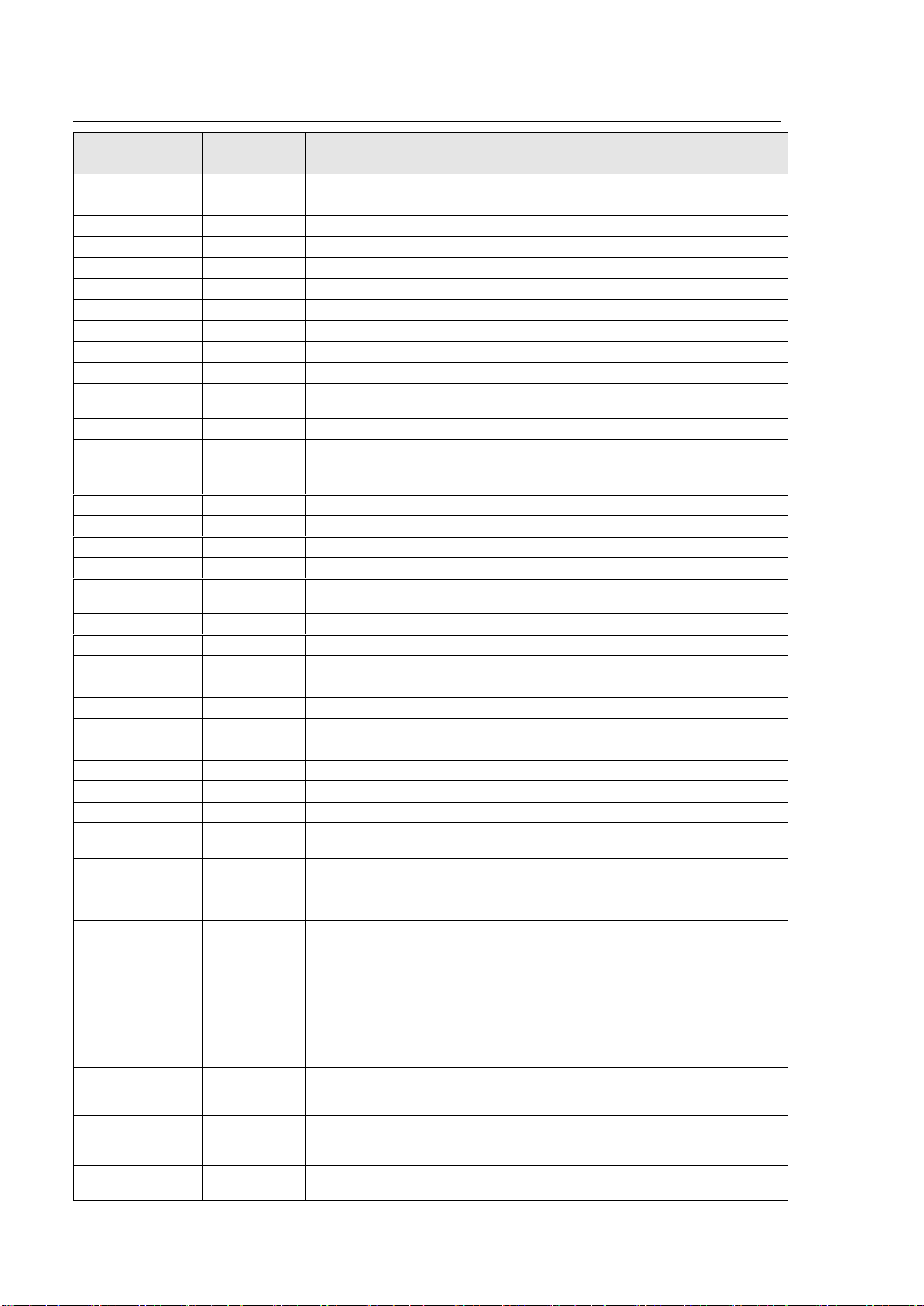
FA-95RU
Indication
DID/SDID
(hexadecimal)
Description
S353MMPEG(V)
08/08
MPEG recoding data, VANC space (Picture rate information)
S353M MPEG(H)
08/0C
MPEG recoding data, HANC space (Other part of recording data set)
S305M SD-SDTI
40/01
ARIB STD-B17 Serial Data Transport Interface for Television
S305M HD-SDTI
40/02
ITU-R BT.1557, SMPTE 348M for HD-SDTI
S427 Lk Enc 1
40/04
SMPTE 427 Link Encryption Message 1
S427 Lk Enc 2
40/05
SMPTE 427 Link Encryption Message 2
S427 Lk Meta
40/06
SMPTE 427 Link Encryption Metadata
S352M VPID
41/01
BTA S-004C Video Payload Identification for Digital Interfaces
S2016-3 AFD-Bar
41/05
SMPTE 2016-3 AFD and Bar Data
S2016-4 PanScan
41/06
SMPTE 2016-3 Pan-Scan Data
RP2010 SCTE
104
41/07
SMPTE 2010 ANSI/SCTE 104 messages
S2031 SCTE VBI
41/08
SMPTE 2010 DVB/SCTE VBI data
ITU-R BT.1685
43/01
ITU-R BT.1685 Inter-station control data packets
RDD8
OP47(SDP)
43/02
SMPTE RDD 8 Subtitling Distribution packet(SDP)
RDD8 OP47(Mult)
43/03
SMPTE RDD 8 Transpotr of ANC packet in an ANC Multipacket
S346M
43/13
Time Division Multiplexing Video Signals and Generic Data over HD-SDI
RP214 KLV(V)
44/04
SMPTE RP 214 KLV Metadata transport in VANC space
RP214 KLV(H)
44/14
SMPTE RP 214 KLV Metadata transport in HANC space
RP223 UMID
44/44
SMPTE RP 223 Packing UMID and Program Identification Label
Data into SMPTE 291M Ancillary Data Packets
S2020 Aud
45/01
SMPTE 2020-1 Compressed Audio Metadata
S2020AudPr1/2
45/02
SMPTE 2020-1 Compressed Audio Metadata
S2020AudPr3/4
45/03
SMPTE 2020-1 Compressed Audio Metadata
S2020AudPr5/6
45/04
SMPTE 2020-1 Compressed Audio Metadata
S2020AudPr7/8
45/05
SMPTE 2020-1 Compressed Audio Metadata
S2020AudPr9/10
45/06
SMPTE 2020-1 Compressed Audio Metadata
S2020AudPr11/12
45/07
SMPTE 2020-1 Compressed Audio Metadata
S2020AudPr13/14
45/08
SMPTE 2020-1 Compressed Audio Metadata
S2020 AudP15/16
45/09
SMPTE 2020-1 Compressed Audio Metadata
RP215 Film Xfer
51/01
RP215 Film Codes in VANC space
ARIB TRB.18
5F/CF
Color information packets standarized in ARIB TR-B18 “Color Frame
Information for Component Interface of 525/60 Television System”
ARIB B.37
1D0
・
・
2DB
Closed caption data packets (for expansion) standarized in ARIB STD-B37
“Structure and Operation of Closed Caption Data Conveyed by Ancillary
Data Packets”
ARIB B.37 Mob
5F/DC
Caption format used in digital television broadcasting for mobile receivers
standarized in ARIB STD-B37“Structure and Operation of Closed Caption
Data Conveyed by Ancillary Data Packets”
ARIB B.37 Ana
5F/DD
Analog signal closed caption data packets standarized in ARIB STD-B37
“Structure and Operation of Closed Caption Data Conveyed by Ancillary
Data Packets”
ARIB B.37 SD
5F/DE
SD signal closed caption data packets standarized in ARIB STD-B37
“Structure and Operation of Closed Caption Data Conveyed by Ancillary
Data Packets”
ARIB B.37 HD
5F/DF
HD signal closed caption data packets standarized in ARIB STD-B37
“Structure and Operation of Closed Caption Data Conveyed by Ancillary
Data Packets”
ARIB TR-B.22
5F/E0
HD ancillary data packet for transmission standarized in ARIB TR-B22
“Operational Guidelines for Transport of the Ancillary Data for HDTV
Contribution”
ARIB TRB23(1)
5F/FA
Dummy packet standarized in ARIB TR-B23 ” Operational Guidelines for
Ancillary Data in Inter-Stationary Information Exchange”
10. FA-95RU Ancillary Data Packet Name List
40
Page 41
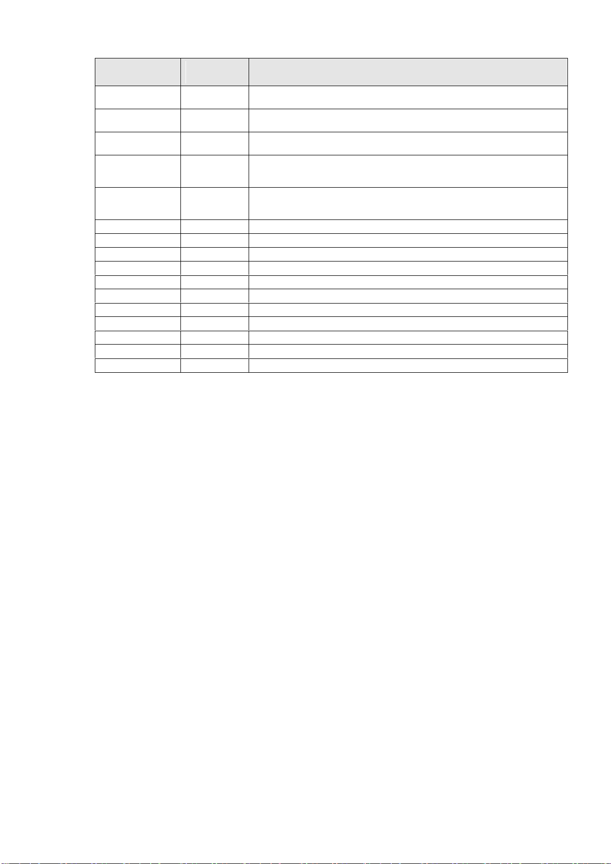
FA-95RU
Indication
DID/SDID
(hexadecimal)
Description
ARIB TRB23(2)
5F/FB
User data 2 in user data packets standarized in ARIB TR-B23 “ Operational
Guidelines for Ancillary Data in Inter-Stationary Information Exchange”
ARIB TRB23(1)
5F/FC
User data 1 in user data packets standarized in ARIB TR-B23 “ Operational
Guidelines for Ancillary Data in Inter-Stationary Information Exchange”
ARIBB.35ProgEx
5F/FD
Trigger signal packets for data broadcasting standarized in ARIB STD-B35
“SD Data Program Exchange Specification for Digital Broadcasting”
ARIB B.39
5F/FE
Control signal packets for inter-studio transmission standarized in ARIB
STD-B39 “Structure of Inter-Stationary Control Data Conveyed by Ancillary
Data Packets”
ARIB B.15
5F/FF
Resource ID packets standarized in ARIB STD-B15 “Resource Identification
Conveyed by Ancillary Data Packets for 52/60 and 1125/60 Television
Systems”
SMPTE 12-2
60/60
ARIB STD-B41 for time code
S334-1CDP(708)
61/01
ITU-R BT.1619, SMPTE 334-1 closed captioning (EIA-708-B)
S334-1 CEA608
61/02
ITU-R BT.1619, SMPTE 334-1 EIA-608 data
S334-1 Teletxt
61/03
World System Teletext Description Packet
S334 SDE
61/04
Subtitling Data Essence (SDE)
334/207
62/01
ITU-R BT.1619, SMPTE RP207 DTV program description
S334-1 Future
62/02
ITU-R BT.1619, SMPTE 334-1 DTV data broadcasting
S334/RP208
62/03
ITU-R BT.1619, SMPTE RP208 VBI data
RP196/LTC
64/64
Time code
RP196/VITC
64/7F
Time code
RP165EDH
1F4
SMPTE error detection indication
41
Page 42
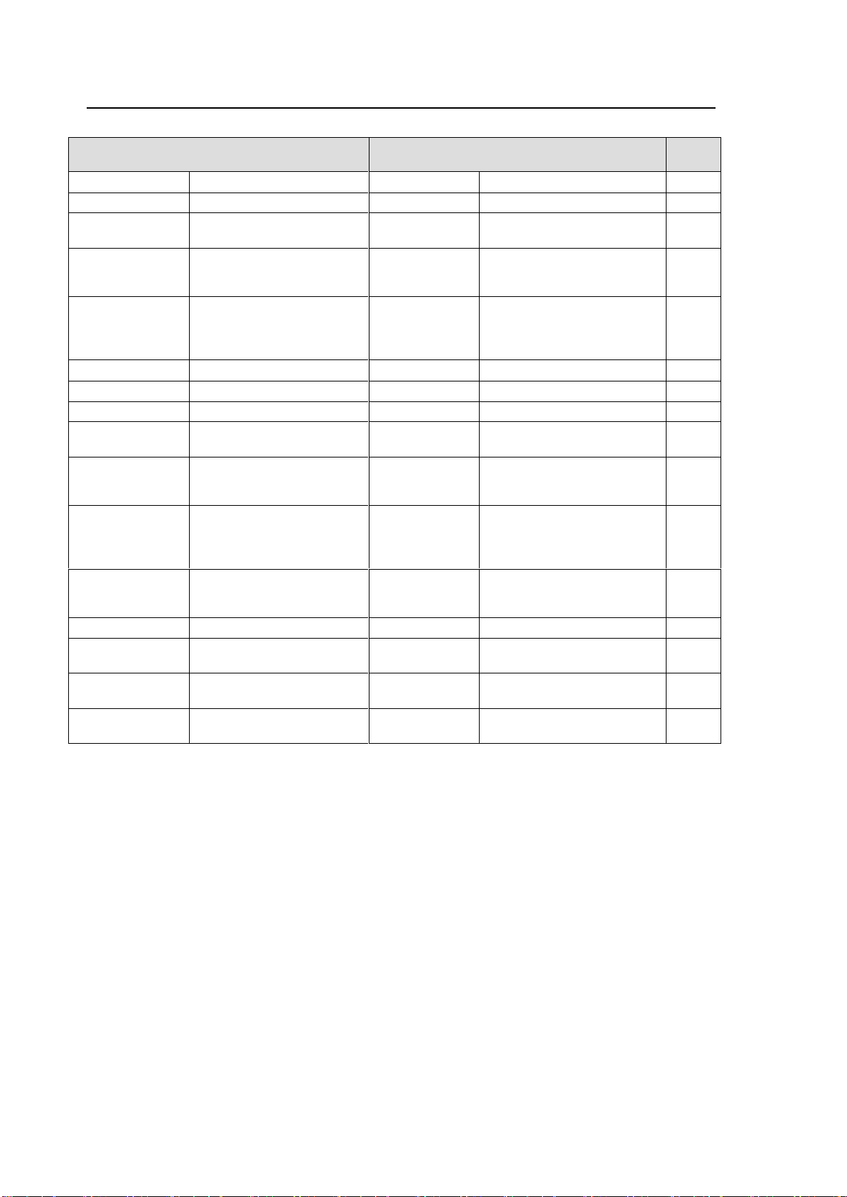
In a 4:3 coded frame
In a 16:9 coded frame
AFD
Code
UNDEFINED
Undefined
UNDEFINED
Undefined
0000
RESERVED
Reserved
RESERVED
Reserved
0001
4:3 L 16:9 T
Letterbox 16:9 image, at
top of the coded frame
16:9 F 16:9
Full frame 16:9 image, the
same as the coded frame
0010
4:3 L14:9 T
Letterbox 14:9 image, at
top of the coded frame
16:9 P 14:9
Pillarbox 14:9 image,
horizontally centered in the
coded frame
0011
4:3 L>16:9
Letterbox image with an
aspect ratio greater than
16:9, vertically centered in
the coded frame
16:9 L>16:9
Letterbox image with an
aspect ratio greater than
16:9, vertically centered in
the coded frame
0100
RESERVED
Reserved
RESERVED
Reserved
0101
RESERVED
Reserved
RESERVED
Reserved
0110
RESERVED
Reserved
RESERVED
Reserved
0111
4:3 F 4:3
Full frame 4:3 image, the
same as the coded frame
16:9 F 16:9
Full frame 16:9 image, the
same as the coded frame
1000
4:3 F 4:3
Full frame 4:3 image, the
same as the coded frame
16:9 P 4:3
Pillarbox 4:3 image,
horizontally centered in the
coded frame
1001
4:3 L16:9PRTD
Letterbox 16:9 image,
vertically centered in the
coded frame with all
image areas protected
16:9 F PRTD
Full frame 16:9 image, with
all image areas protected
1010
4:3 L 14:9
Letterbox 14:9 image,
vertically centered in the
coded frame
16:9 P 14:9
Pillarbox 14:9 image,
horizontally centered in the
coded frame
1011
RESERVED
Reserved
RESERVED
Reserved
1100
4:3 F ALT14:9
Full frame 4:3 image, with
alternative 14:9 center
16:9P ALT14:9
Pillarbox 4:3 image, with
alternative 14:9 center
1101
4:3 L ALT14:9
Letterbox 16:9 image, with
alternative 14:9 center
16:9F ALT14:9
Full frame 16:9 image, with
alternative 14:9 center
1110
4:3 L ALT 4:3
Letterbox 16:9 image, with
alternative 4:3 center
16:9 F ALT4:3
Full frame 16:9 image, with
alternative 4:3 center
1111
10-1. AFD Code Abbreviations
SMPTE S2016-3 AFD aspect ratio table
42
Page 43
Description
AFD Code
RESERVED
Reserved
0000
RESERVED
Reserved
0001
BOX 16:9 TOP
Box 16:9 (top)
0010
BOX 14:9 TOP
Box 14:9 (top)
0011
BOX>16:9 CTR
Box > 16:9 (center)
0100
RESERVED
Reserved
0101
RESERVED
Reserved
0110
RESERVED
Reserved
0111
AS THE CD FRM
Active format is the same as coded frame
1000
4:3 CTR
4:3 (center)
1001
16:9 CTR
16:9 (center)
1010
14:9 CTR
14:9 (center)
1011
RESERVED
Reserved
1100
4:3 WITH 14:9 PRTD
4:3 (with shoot and protect 14:9 center)
1101
16:9 WITH 14:9 PRTD
16:9 (with shoot and protect 14:9 center)
1110
16:9 WITH 4:3 PRTD
16:9 (with shoot and protect 4:3 center)
1111
Description
AFD Code
F 4:3
full format 4:3
1000
BOX 14:9 CTR
box 14:9 centre
0001
BOX 14:9 TOP
box 14:9 top
0010
BOX 16:9 CTR
box 16:9 centre
1011
BOX 16:9 TOP
box 16:9 top
0100
BOX>16:9 CTR
box 16:9 centre
1101
F 14:9 CTR PRTD
full format 14:9 centre shoot and protect 14:9
1110
F 16:9 AMRPH
full format 16:9 anamorphic
0111
SMPTE RP186-2008 VI AFD aspect ratio table
ITU-R BT.1119-2 WSS aspect ratio table
43
Page 44
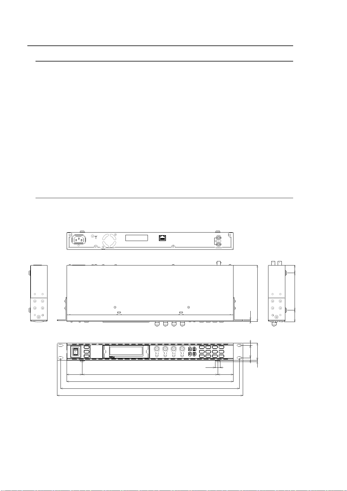
Interfaces
LAN
10 Base-T / 100 Base-TX / 1000 Base-T, RJ-45 x 1
Temperature
0ºC to 40ºC
Humidity
30% to 90% (no condensation)
Power
100 VAC to 240 VAC ±10%, 50/60 Hz
Consumption
14VA, 13 W (at 100 VAC to 120 VAC),
20VA, 12 W (at 220 VAC to 240 VAC)
Dimensions
430 (W) x 145 (D) x 44 (H) mm
Weight
2.2 kg
Consumables
(Recommended replacement timespans)
Power unit (within 5 years)
Cooling fan: P1467-1 (within 5 years)
Accessories
Operation manual, AC cord, rack mount brackets
‚U
480
462
430
350 40
12. 7
3. 7
2
145
40
32
44
6
t 2.3
30 95 20
DISPLAY AREA
POWER
ON
OFF
LOCK
MU
SELECT
EVENT
BY-PASSVIDEO IN
AUDIO IN FAN ALARM
GENLOCK
REMOTE
F 1
F 2
F 3
F 4
R EM OT E CO NT R OL U NI TF A- 95 RU
F1
F2
F3
F4
UNITYUNITY UNITY UNITY
PROCESS
SDI AUDIO
C C
AES AUDIO
CONV1
ANALOG
CONV2
MASTER
AVO
MAPPING
CLIP
DELAY
DOWNMIX
IN SEL OUT SEL
MODE
AUDIO OP
VIDEO OP VIDEO SYS
AUDIO SYS
STATUS
OTHER
VIDEO
AUDIO
IN
OUT
(FA-9000/9100)
TO MU
TO MU
(FA-9500)
(10/100/1000BASE-T X)
RATING LABEL
AC100-240V 50/60Hz IN
11. Specifications and Dimensions
11-1. Unit Specifications
11-2. External Dimensions
44
(All dimensions in mm)
Page 45

Index
A
AC Cord Retaining Clip 7
Accessing Menus 18
AFD Code Abbreviations 45
Ancillary Data Packet Name List 43
Arrow Buttons 19
B
Backup & Restore (Web) 37
Basic Operations 17
C
Changing and Viewing FA-95RU Settings 27
Changing Setting Values 20
Configuration Data Backup (Web) 38
CONNECT STATE 26
Connections 16
Consecutive Viewing of Settings 19
D
Dipswitch Settings 15
E
Establishing Connection with the FA-9500 25
Event Data Backup (Web) 40
EVENT LOAD 29
Event Memory 29
Event Naming (Web) 34, 36
EVENT SAVE 30
EVENT SETUP 30
External Dimensions 47
F
FA-9500 Ver 28
FA-95RU INFO 27
FA-95RU NET WORK INFO 27
FRONT OPERATION 28
Front Panel 12
Front Panel Operations 17
FRONT PANEL SET 27
I
Infomation (Web) 32
Internal Settings 15
IP Address Selection Mode 25
N
Network Settings (Web) 33
Note on Event Memory Operation 31
O
Other Settings & Information (OTHER) 28
P
Parameters That Are Not Stored in Event
Memories 31
Powering ON 17
R
Rear Panel 14
Resetting to Default 21
Restart (Web) 41
S
Specifications 47
Switching Between 2-Channel Frame
Synchronizers 22, 23
System Requirements 42
U
Unit ID Assignment (Web) 34
Unit ID Selection Mode 25
Unpluging the AC cord 7
User Account Settings (Web) 33
W
WEB Browser Settings 32
45
Page 46

Page 47

Warning
This equipment has been tested and found to comply with the limits for a
Class A digital device, pursuant to Part 15 of FCC Rules. These limits are
designed to provide reasonabl e protection against harmful interference
when the equipment is operated in a commercial environment. This
equipment generates, uses, and can radiate radio frequency energy and, if
not installed and used in accordance with the instruction manual, may
cause harmful interference to radio communications. Operation of this
equipment in a residential area is likely to cause harmful interference, in
which case the user will be required to correct the interference at his own
expense.
Page 48

05/31/2013 Printed in Japan
FOR-A COMPANY LIMITED
Head Office 3-8-1 Ebisu, Shibuya-ku, Tokyo 150-0013, Japan
Overseas Division Phone: +81(0)3-3446-3936, Fax: +81(0)3-3446-1470
Japan Branch Offices Osaka/Okinawa/Fukuoka/Hiroshima/Nagoya/Sendai/Sapporo
R&D/Production Sakura Center/Sapporo Center
FOR-A America Corporate Office
11155 Knott Ave., Suite G&H, Cypress, CA 90630, USA
Phone: +1-714-894-3311 Fax: +1-714-894-5399
FOR-A America East Coast Office
2 Executive Drive, Suite 670, Fort Lee Executive Park, Fort Lee, NJ 07024, USA
Phone: +1-201-944-1120 Fax : +1-201-944-1132
FOR-A America Distribution & Service Center
2400 N.E. Waldo Road, Gainesville, FL 32609, USA
Phone: +1-352-371-1505 Fax: +1-352-378-5320
FOR-A Corporation of Canada
346A Queen Street West, Toronto, Ontario M5V 2A2, Canada
Phone: +1-416-977-0343 Fax: +1-416-977-0657
FOR-A Latin America & the Caribbean
5200 Blue Lagoon Drive, Suite 760, Miami, FL 33126, USA
Phone: +1-305-931-1700 Fax: +1-305-264-7890
FOR-A UK Limited
UNIT C71, Barwell Business Park, Leatherhead Road, Chessington Surrey, KT9 2NY, UK
Phone: +44(0)20-8391-7979 Fax: +44(0)20-8391-7978
FOR-A Italia S.r.l.
Via Volturno 37, 20047 Brugherio MB, Italy
Phone: +39-039-881-086/103 Fax: +39-039-878-140
FOR-A Corporation of Korea
1007, 57-5,Yangsan-ro,Yeongdeungpo-gu, Seoul 150-103, Korea
Phone: +82(0)2-2637-0761 Fax: +82(0)2-2637-0760
FOR-A China Limited
708B Huateng Bldg., No. 302, 3 District, Jinsong, Chaoyang, Beijing 100021, China
Phone: +86(0)10-8721-6023 Fax: +86(0)10-8721-6033
FOR-A Middle East-Africa Office
Jebel Ali Free Zone, LOB-16, Office 619, P. O. Box: 261914 Dubai, UAE
Phone: +971 4 887 6712 Fax: +971 4 887 6713
*The contents of this manual are subject to change without notice.
 Loading...