


Technical Manuals
FONA XPan 3D_
English

Technical Manuals
ITALIANO
2

FONA XPan 3D
Table of contents |
|
||
1. INSTALLATION INSTRUCTIONS ................................................................................................................... |
6 |
||
1.1. |
DELIVERY CHECK LIST........................................................................................................................... |
7 |
|
1.1.1. |
Necessary Tools................................................................................................................................ |
10 |
|
1.2. |
GENERAL................................................................................................................................................ |
11 |
|
1.2.1. |
System Components ......................................................................................................................... |
11 |
|
1.2.2. |
Control panel (touchscreen) .............................................................................................................. |
12 |
|
1.3. |
ROOM PREPARATION........................................................................................................................... |
13 |
|
1.4. |
POSSIBILITIES OF INSTALLATION ...................................................................................................... |
15 |
|
1.5. |
HAND-SWITCH CONNECTION.............................................................................................................. |
16 |
|
1.6. |
FACILITIES AND OPTIONAL.................................................................................................................. |
17 |
|
1.7. |
ASSEMBLING THE SYSTEM ................................................................................................................. |
18 |
|
1.7.1. |
Unpacking.......................................................................................................................................... |
18 |
|
1.7.2. |
Preparing the column for wall mounting ............................................................................................ |
20 |
|
1.7.3. |
Preparing the column for floor mounting (Optional) .......................................................................... |
21 |
|
1.7.4. |
Mounting system body to the column................................................................................................ |
22 |
|
1.7.5. |
Lifting and securing the system......................................................................................................... |
24 |
|
1.7.6. |
Removing safety bolts and transport bracket .................................................................................... |
25 |
|
1.8. |
ELECTRICAL CONNECTIONS............................................................................................................... |
26 |
|
1.8.1. |
Configuring the power supply unit ..................................................................................................... |
26 |
|
1.8.2. |
Connecting the motor for vertical movement .................................................................................... |
27 |
|
1.8.3. |
Connecting the hand-switch and other facilities ................................................................................ |
28 |
|
1.8.4. |
Connecting the remote hand-switch option ....................................................................................... |
29 |
|
1.8.5. |
Connecting the external lights and door contact ............................................................................... |
30 |
|
1.8.6. |
Connecting the system to the mains line .......................................................................................... |
31 |
|
1.8.7. |
Connecting the column to protective earth........................................................................................ |
32 |
|
1.9. |
SYSTEM START-UP............................................................................................................................... |
33 |
|
1.9.1. |
Preparing the unit for test .................................................................................................................. |
33 |
|
1.9.2. |
Performing system test without radiation .......................................................................................... |
35 |
|
1.9.3. |
Tuning the side bearings on vertical travel........................................................................................ |
36 |
|
1.10. CONNECTING THE UNIT TO THE PC .................................................................................................. |
37 |
||
1.11. FINAL TEST ............................................................................................................................................ |
38 |
||
1.11.1. Taking an exam ................................................................................................................................. |
38 |
||
1.11.2. Degassing procedure ........................................................................................................................ |
38 |
||
1.11.3. Checking power supply adequacy..................................................................................................... |
39 |
||
1.12. FINAL WORK .......................................................................................................................................... |
40 |
||
1.12.1. Setting the unit for demostrations (when applicable) ............................................................................. |
40 |
||
1.12.2. Putting covers back ........................................................................................................................... |
41 |
||
1.12.3. Filling the installation report and warranty passport .......................................................................... |
42 |
||
1.13. INSTALLATION REPORT ....................................................................................................................... |
43 |
||
2. SERVICE INSTRUCTIONS............................................................................................................................ |
44 |
|
2.1. FUNCTIONAL DESCRIPTION ................................................................................................................ |
45 |
|
2.1.1. |
Block diagram.................................................................................................................................... |
45 |
2.1.2. |
PCB Displacement ............................................................................................................................ |
46 |
2.1.3. |
Mains connection module.................................................................................................................. |
47 |
2.1.4. |
Column motor driver board................................................................................................................ |
48 |
2.1.5. |
System fuses ..................................................................................................................................... |
49 |
2.1.6. |
Power supply unit .............................................................................................................................. |
50 |
2.1.7. |
Power switching unit JED 28............................................................................................................. |
52 |
2.1.8. |
Control unit ........................................................................................................................................ |
53 |
2.1.9. |
Multiplexer Board............................................................................................................................... |
55 |
2.1.10. |
Network scheme................................................................................................................................ |
57 |
2.1.11. |
Modbus .............................................................................................................................................. |
58 |
2.1.12. |
3D Ethernet sensor............................................................................................................................ |
59 |
3

Technical Manuals
2.1.13. Tube-Housing assembly.................................................................................................................... |
60 |
|||
2.2. |
SERVICE FUNCTIONS ........................................................................................................................... |
62 |
||
2.2.1. |
PAN Alignment .................................................................................................................................. |
62 |
||
2.2.1.1.Rotation Axis...................................................................................................................................... |
62 |
|||
2.2.1.2.X Axis................................................................................................................................................. |
63 |
|||
2.2.1.3.C Axis ................................................................................................................................................ |
64 |
|||
2.2.1.4.Rot. Dev............................................................................................................................................. |
66 |
|||
2.2.1.5.Coll. Dev. ........................................................................................................................................... |
67 |
|||
2.2.1.6.Prim. Coll. Slit. ................................................................................................................................... |
67 |
|||
2.2.2. |
Languages ......................................................................................................................................... |
68 |
||
2.2.3. |
Tube head statistics........................................................................................................................... |
68 |
||
2.2.4. |
Exposure setting ................................................................................................................................ |
69 |
||
2.2.5. |
Battery change................................................................................................................................... |
70 |
||
2.2.6. |
Software info...................................................................................................................................... |
70 |
||
2.2.7. |
DAP setting........................................................................................................................................ |
71 |
||
2.2.8. |
Cam Offset......................................................................................................................................... |
71 |
||
2.2.8.1.Cam Offset 2D ................................................................................................................................... |
72 |
|||
2.2.8.2.Cam Offset 3DTMJ ............................................................................................................................ |
72 |
|||
2.2.8.3.Cam Offset 3D ................................................................................................................................... |
73 |
|||
2.2.9. |
Thermal setting .................................................................................................................................. |
73 |
||
2.2.9.1.Enable/Disable thermal control.......................................................................................................... |
73 |
|||
2.2.9.2.Thermal values editor ........................................................................................................................ |
74 |
|||
2.2.10. Keyboard Test ................................................................................................................................... |
74 |
|||
2.2.11. LEDS Test ......................................................................................................................................... |
75 |
|||
2.2.12. Automatic Test................................................................................................................................... |
75 |
|||
2.2.12.1. 100 PAN NO X-Ray ................................................................................................................... |
76 |
|||
2.2.12.2. 10 PAN + X-ray .......................................................................................................................... |
76 |
|||
2.2.13. X-Ray Test......................................................................................................................................... |
76 |
|||
2.2.13.1. |
Continued X-Ray........................................................................................................................ |
77 |
||
2.2.13.2. |
Pulsed X-Ray ............................................................................................................................. |
77 |
||
2.2.14. Encoders Test.................................................................................................................................... |
77 |
|||
2.2.14.1. |
Rotation Axis .............................................................................................................................. |
78 |
||
2.2.14.2. |
C Axis ......................................................................................................................................... |
78 |
||
2.2.14.3. |
X Axis ......................................................................................................................................... |
78 |
||
2.2.15. Voltages Test..................................................................................................................................... |
79 |
|||
2.2.16. kV Mod Offset .................................................................................................................................... |
80 |
|||
2.3. |
SERVICE PROCEDURES....................................................................................................................... |
81 |
||
2.3.1. |
Plastic covers..................................................................................................................................... |
81 |
||
2.3.2. |
Metal covers (Shields) ....................................................................................................................... |
82 |
||
2.3.3. |
PCBs/Tube head replacement .......................................................................................................... |
83 |
||
2.3.4. Filament calibration and Feedback signal calibration........................................................................ |
84 |
|||
2.3.5. |
X-Ray Beam Alignment ..................................................................................................................... |
85 |
||
2.3.5.1.X-Ray Beam alignment – 3D Exams ................................................................................................. |
85 |
|||
2.3.5.2.X-Ray Beam alignment – 2D Exams ................................................................................................. |
88 |
|||
2.3.5.3.Collimator alignment .......................................................................................................................... |
91 |
|||
2.3.6. |
X-Ray Beam Calibration .................................................................................................................... |
92 |
||
2.3.6.1.X-Ray Beam calibration – 3D Exams ................................................................................................ |
92 |
|||
2.3.6.2.X-Ray Beam calibration – 2D Exams ................................................................................................ |
98 |
|||
2.3.7. |
Calibration files ................................................................................................................................ |
102 |
||
2.3.8. Replacement of position sensors .................................................................................................... |
103 |
|||
2.4. |
SYSTEM MESSAGES........................................................................................................................... |
104 |
||
2.4.1. |
Warning Messages .......................................................................................................................... |
104 |
||
2.4.2. |
Error messages ............................................................................................................................... |
104 |
||
2.4.3. |
Other Alarms.................................................................................................................................... |
106 |
||
2.5. |
ELECTRICAL SCHEMES...................................................................................................................... |
107 |
||
4

|
|
|
FONA XPan 3D |
2.5.1. |
Mains connection module................................................................................................................ |
107 |
|
2.5.2. |
Dual Power Supply .......................................................................................................................... |
108 |
|
2.5.3. |
Driver Motor Column ....................................................................................................................... |
109 |
|
2.5.4. |
Power Switching Unit....................................................................................................................... |
110 |
|
2.5.5. |
Control unit ...................................................................................................................................... |
111 |
|
2.5.6. |
Multiplexer ....................................................................................................................................... |
112 |
|
3. MAINTENANCE INSTRUCTIONS ............................................................................................................... |
113 |
||
3.1. |
VISUAL CHECK .................................................................................................................................... |
114 |
|
3.2. |
KEYBOARD TEST ................................................................................................................................ |
115 |
|
3.3. |
LIGHT AND SOUND INDICATORS ...................................................................................................... |
116 |
|
3.4. |
PHANTOM RADIOGRAPH ................................................................................................................... |
118 |
|
3.4.1. |
Panoramic Exams ........................................................................................................................... |
118 |
|
3.5. |
AIMING LIGHTS.................................................................................................................................... |
119 |
|
3.6. |
MECHANICAL MOVEMENTS VERIFICATION .................................................................................... |
120 |
|
3.7. |
POWER SUPPLY ADEQUACY............................................................................................................. |
120 |
|
3.8. |
ANODE VOLTAGE VERIFICATION ..................................................................................................... |
121 |
|
3.9. |
ANODE CURRENT VERIFICATION..................................................................................................... |
123 |
|
3.10. CHECKING THE X-RAY BEAM ALIGNMENT ...................................................................................... |
124 |
||
3.10.1. Panoramic Mode ............................................................................................................................. |
124 |
||
3.10.2. |
3D Mode .......................................................................................................................................... |
124 |
|
3.11. INSPECTION CHECKLIST FORMS ..................................................................................................... |
124 |
||
3.12. Forms..................................................................................................................................................... |
125 |
||
5

Technical Manuals
|
|
1. |
INSTALLATION INSTRUCTIONS |
ATTENTION |
|
|
To guarantee the operational safety of medical devices, it is recommended |
Interference |
with |
medical |
that the operation of mobile radio telephones in the medical practice or |
devices by radio telephones |
hospital is prohibited. |
||
ATTENTION |
|
|
This product incorporates Class 1 lasers as light localizers for the |
Laser light localizers used |
positioning of the patient. They must not be used for other purposes. A |
||
|
|
|
minimum distance of 100 mm must be maintained between the eye and |
|
|
|
the laser. Avoid unnecessary exposure of the eyes and pay attention that |
|
|
|
the beams are not intercepted by any optical device. |
NEW SINCE |
|
|
09.2018 |
MANUFACTURED BY |
|
|
FONA S.r.l. Via Galilei 11 - 20090 Assago (MI), Italy |
DISTRIBUTED BY |
|
|
FONA Dental s.r.o. Stefanikova 7 SK-811 06 Bratislava, Slovakia |
|
|
|
www.fonadental.com |
6
FONA XPan 3D
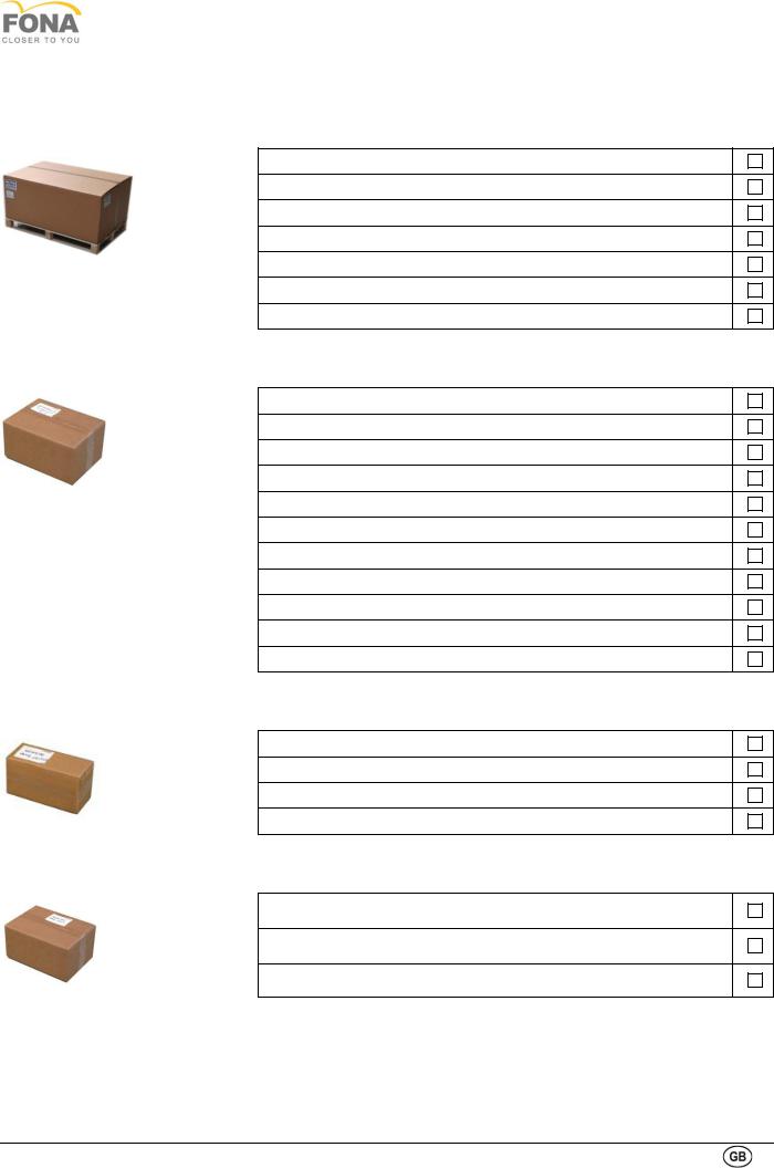
1.1. DELIVERY CHECK LIST
Check list of system body box (120x80x70cm - 90kg)
1. System body
2. Set of top covers
3. Mirror cover
4. Computer
5. Accessory box
6. Kit for remote hand switch (optional)
7. Temporal resting bar (optional)
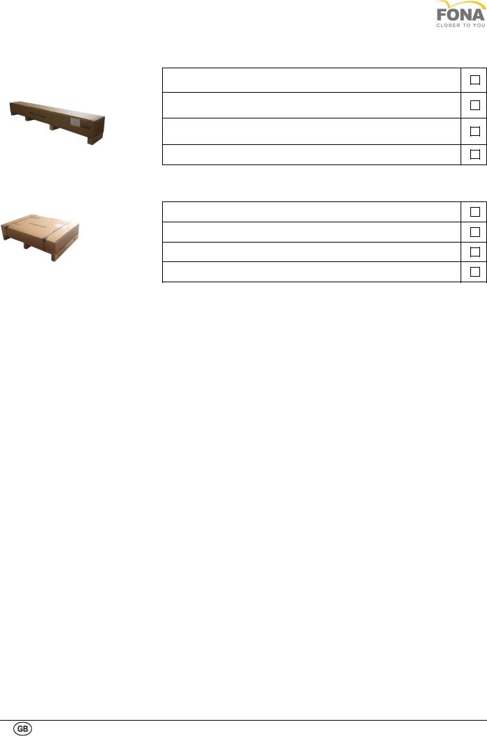
Check list of accessory box
1. Chin rest and bite block kit
2. Assembly limit switches for column
3. Bite blocks (yellow and blue)
4. Nasal support for edentulous (yellow and blue)
5. Spare bolts and washers
6. Test phantom
7. Hand switch with cable
8. FONA Logostrip
9. Manuals
10. CD OrisWin DG Suite Software
11. Copper filter 0.5 mm (2 pieces)
Check list of optional kit for remote hand switch (optional)
1. Plastic box
2. Hand-switch
3. 10 m 4 wires cable
4. Coiled cable
Check list of optional box temporal resting bar (optional)
1. Gear box with temporal bars
2. Mounting bolt (set of 2)
3. Resting bar tips (set of 4)
7
Technical Manuals
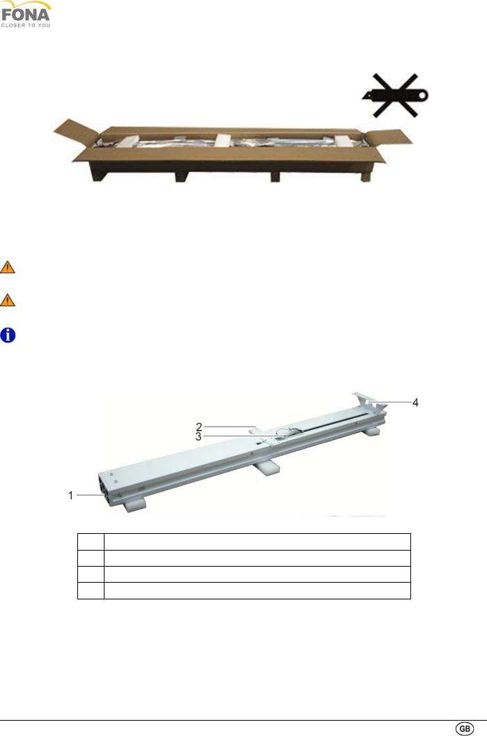
Check list of motorized column box (229x31x33cm - 42kg)
1. Motorized column
2.Bolts and washers for wall support (set of two 8x20 with split washers)
3.Bolts and spacers for carriage holding PLATE (set of 4 8x30)
4. Wall support
Check list of optional self-standing base (96x70x28cm - 38kg)
1. Self-standing base
2. Plastic cover
3. Mounting bolt 10x25 (set of 6)
4. Levelling screw (set of 4)
8
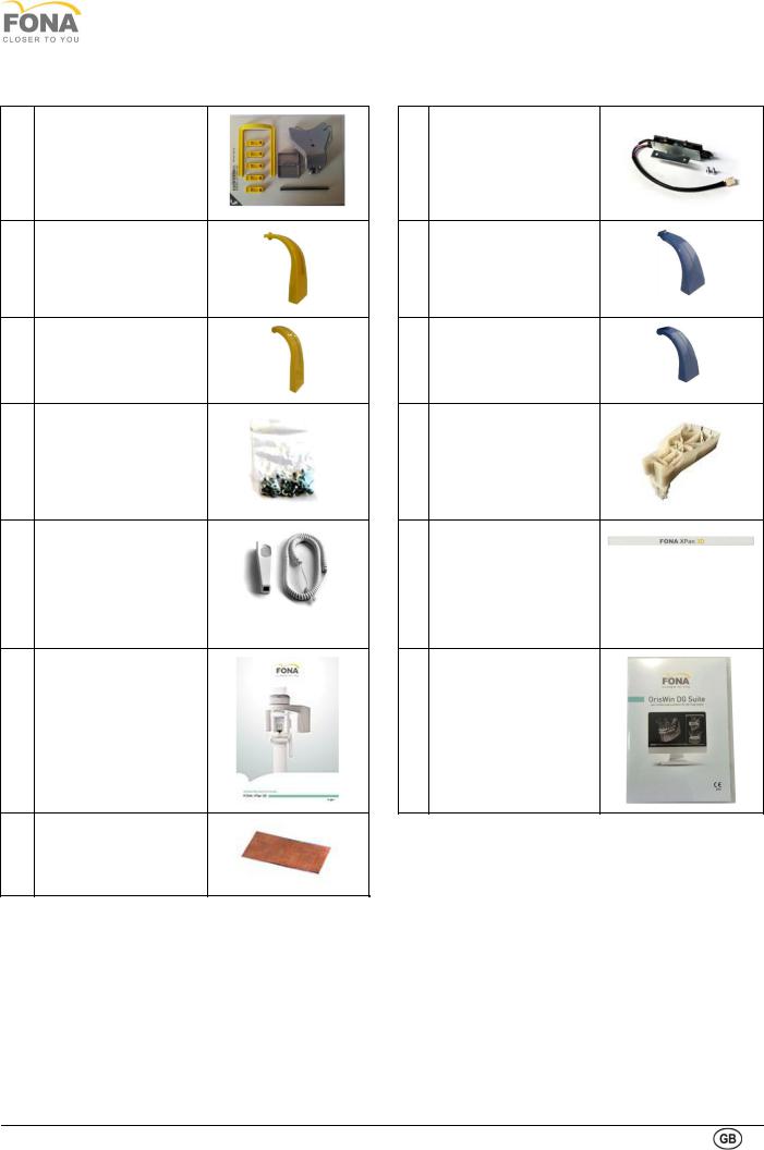
Pictorial view of items in accessory box
1Chin rest and bite block kit
3Bite block
4Nasal support for edentulous
5Spare bolts and washers
7Hand switch with coiled cable
9 Manuals
11 Copper |
filter |
0.5 mm |
|
(set of 2) |
|
FONA XPan 3D
2Assembly limit switches for column
3Bite block for TMJ and sinus exams
4Nasal support for TMJ and sinus exams
6 Test phantom
8 FONA logostrip
10 CD OrisWin DG Suite
Software
9

Technical Manuals
1.1.1. Necessary Tools
In order to perform FONA XPan 3D system assembly and installation the following tools are required.
1Flat head screwdriver, medium size and small size
2Phillips screwdriver, medium size and small size
3A pair of scissors
4Open-end wrench 8 and 13 mm
5Allen keys
2, 2.5, 3, 6, 8 mm
6Electrical AC /DC multimeter,
10 VDC, 250 VAC, 1% accuracy or better, complete with test leads with hooks or alligator clips
7Spirit level (max 20 cm)
8Copper filter
size 4x8 cm, 0.5 mm thick
9Technical needles test phantom
10
FONA XPan 3D
1.2. GENERAL
1.2.1. System Components
1 |
Vertical Carriage |
|
6 |
X-Ray generator |
|
|
|
|
|
2 |
Rotating Arm |
|
7 |
Control Panel (see next page) |
|
|
|
|
|
3 |
PAN/3D Sensor |
|
8 |
Column |
|
|
|
|
|
4 |
Bite support |
|
9 |
Wall Support |
|
|
|
|
|
5 |
Up/down keys |
|
10 |
Self-supporting base |
|
|
|
|
|
11
Technical Manuals
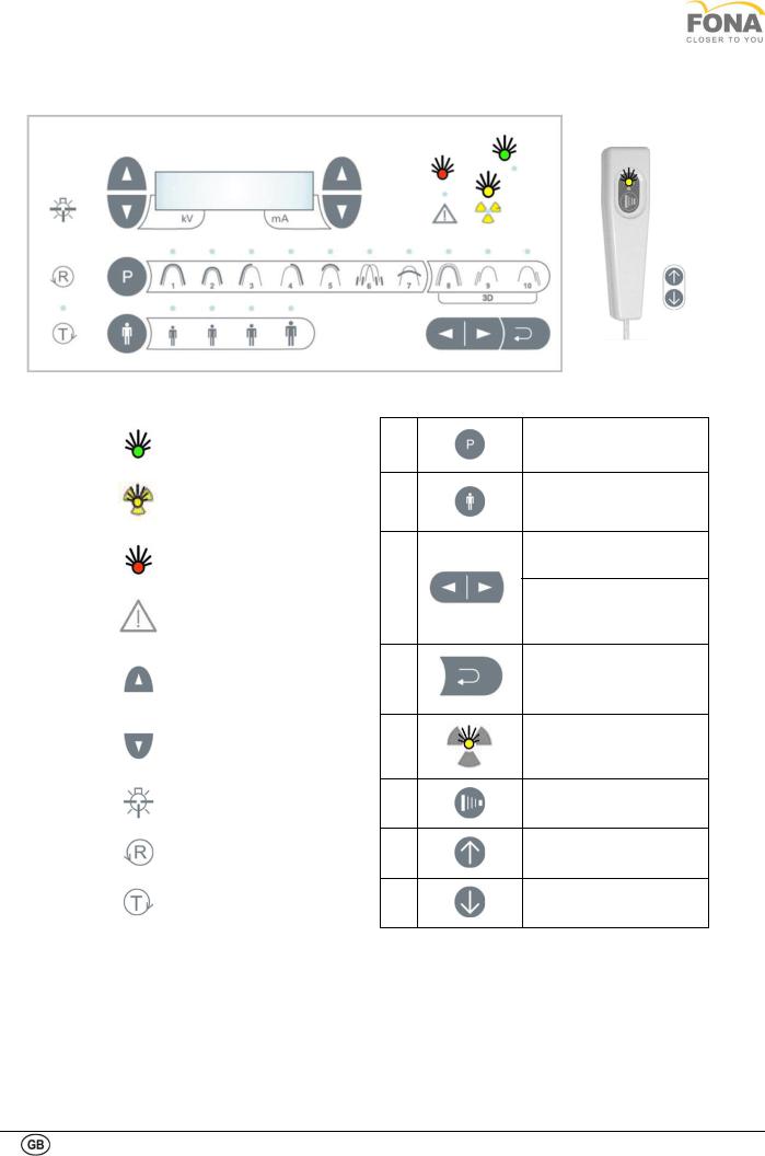
1.2.2. Control panel (touchscreen)
1 |
|
System ON and ready |
|
|
|
2 |
|
X-ray emission |
|
|
|
|
|
ALARM or ERROR: |
3 |
|
see Warning or Error |
|
messages in the Service |
|
|
|
|
|
|
Chapter |
|
|
|
|
|
INCREASE: kV(left), |
|
|
mA(right) |
4 |
|
|
|
DECREASE: kV(left), |
|
|
|
|
|
|
mA(right) |
|
|
|
5 |
|
LIGHT beams: |
|
LASER beams on (30 s) |
|
|
|
|
|
|
|
6 |
|
RETURN |
|
|
|
7 |
|
TEST MODE |
|
|
|
8
9
10
11
12
13
14
15
PROGRAM Selection
PATIENT build: small, medium, large, extra large
FORWARD Shift (referred to patient)
BACKWARD Shift (referred to patient)
BACK to patient entrance position /Alarm Reset
X-ray Indicator
(Ionizing Radiation
Emission)
X-RAY control button
UP movement (on the sides of the carriage)
DOWN movement (on the sides of the carriage)
12
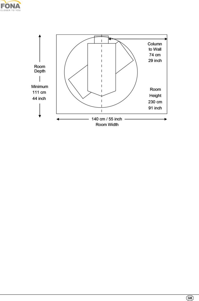
1.3. ROOM PREPARATION
Room layout
Room Survey
A visit to the installation site has to be planned to prepare the room.
Room size
•Minimum room required:
cm 140x111x229 (inch 55x44x89)
•Wall support at 210 cm (82” 11/16) from the floor.
•The use of self standing base requires that the same is secured to the floor with adequate bolts.
Electrical issues
•The connection to the mains line has to be intercepted by a safety switch to disconnect the equipment from the mains when needed.
•The connection to the mains line has to be made on the wall on just on the left side of the column at about 80 cm (31”) from the floor.
•In case of need the exposure hand-switch can be placed remotely using a 4 wire cable (kit for remote mounting is available). Consider the possibility to have the remote hand-switch cable in the wall exiting close to the point of connection to the mains line.
•Cables for external lights to indicate X-ray unit ON and X-ray radiation ON plus one cable for door contact have to be prepared if needed.
FONA XPan 3D
•Consider the possibility to have the external lights cables in the wall exiting close to the point of connection to the mains line.
Radiation Protection
•The system is equipped with lead barriers
to cut residual radiation. Shielding to the walls may be required depending on local regulations.
Data Communication
•The connection to the computer for data acquisition is made with two Ethernet cables (Cat. 6) 25 foot long (about 10 m) supplied with the system.
Computer
•The computer to be compatible in relation to hardware and software (operating system) requirements and safety.
•It is recommended that the computer and other additional devices for image acquisition, processing, and printing comply with the requirements of the safety standard IEC EN 60601-1.
•If not, such hardware must stay outside the patient area, i.e. at an horizontal distance greater than 1.5 m from the patient or more than 2.5 m from the floor, and it is
recommended that be compliant with the requirements of the standard IEC EN 60950
13

Technical Manuals
Overview of electrical connections in the room
14
FONA XPan 3D
1.4. POSSIBILITIES OF INSTALLATION
The unit can be installed in three ways according to the wall condition and material: unit installed with wall bracket only, with self standing base only, in case the wall it is not suitable for fixation or wall bracket and self standing base together, which is providing the maximum stability to the device.
The recommended bolt sizes are listed in the table below:
Diameter |
Class |
Core Section mm2 |
M 8X1.25 |
ISO 8.8 |
36.6 |
M 8X1 |
ISO 8.8 |
39.2 |
5/16” – 18 UNC |
SAEGrade 5 |
33.8 |
5/16’’ – 24 UNF |
SAEGrade 5 |
37.41 |
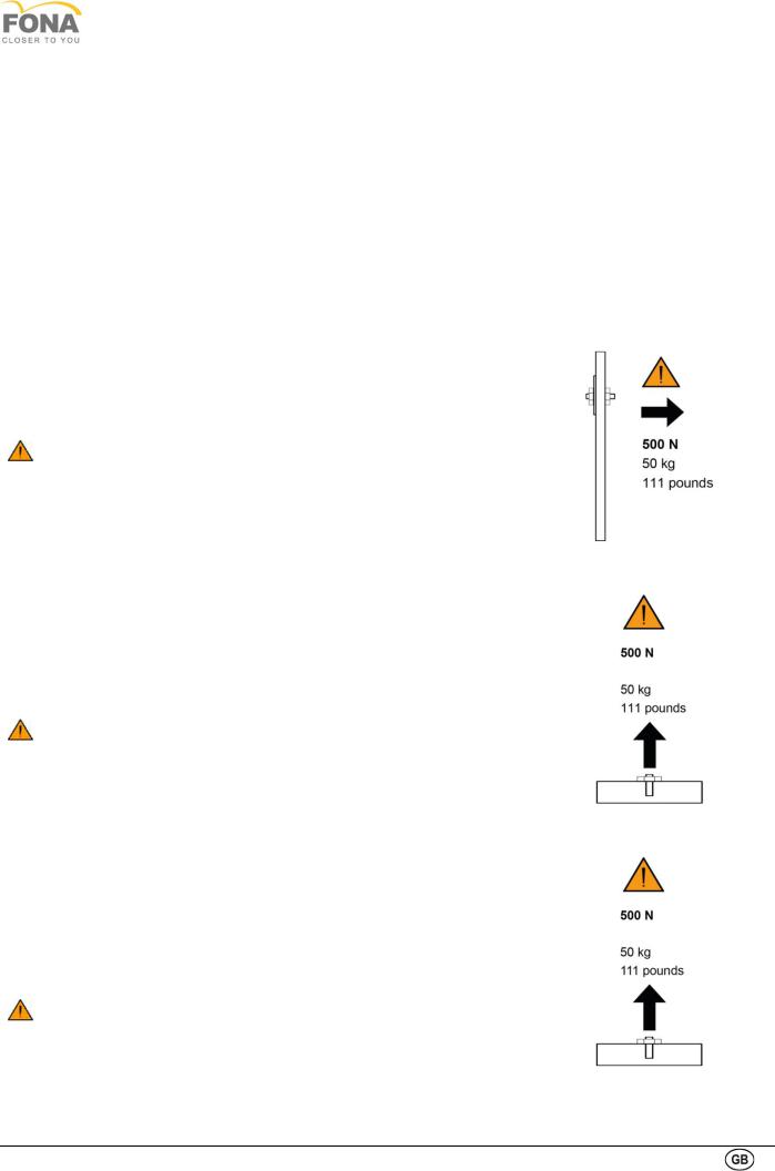
A Unit wall connected
The unit is connected to the wall with two bolts, using the wall bracket only.
WARNING Wall anchors! Each wall plug must withstand a pull of 500N (50kp /111pounds). Depending on the construction of the wall, suitable special wall anchors must be used or an anchor PLATE custom made.
INSUFFICIENT WALL OR HARDWARE STRENGHT MAY CAUSE THE WALL HOLDER TO PULL OUT FROM THE WALL AND THE FULL SYSTEM TO FALL ON PATIENT OR OPERATOR CAUSING INJURIES.
B Use of self standing base
A self standing base is optionally available.
The self standing base must be secured to the floor with four anchors (pull force normally on two back anchors).
WARNING Floor anchors! Each floor anchor must withstand a pull of 500N (50kp /111pounds). Depending on the construction of the floor, suitable special anchors must be obtained.
INSUFFICIENT FLOOR OR HARDWARE STRENGHT MAY CAUSE THE SELF STANDING BASE TO PULL OUT FROM THE FLOOR AND THE FULL SYSTEM TO FALL ON PATIENT OR OPERATOR CAUSING INJURIES.
C Use of self standing base and additional wall bracket
The use of self standing base and wall bracket is providing maximum stability to the system. The self standing base must be ordered separatelyas optional. The self standing base must be secured to the floor with four anchors (pull force normally on two back anchors).
WARNING Floor anchors! Each floor anchor must withstand a pull of 500N (50kp /111pounds). Depending on the construction of the floor, suitable special anchors must be used.
INSUFFICIENT FLOOR OR HARDWARE STRENGHT MAY CAUSE THE SELF-STANDING BASE TO PULL OUT FROM THE FLOOR AND THE FULL SYSTEM TO FALL ON PATIENT OR OPERATOR CAUSING INJURIES.
15

Technical Manuals
1.5. HAND-SWITCH CONNECTION
The hand-switch can be installed in three different ways by following the local regulation of your County and the will of the end-user.
A. Hand-switch on the unit in the treatment room
The unit is provided with hand-switch with coiled cable on the right side for use up to 3 m distance.
B. Hand-switch remote
A kit for mounting of the hand-switch remotely outside of the X-ray room is optionally available.
The kit is provided with a 4 wire cable 10 m (39 in) long and termination box with magnet for the hand-switch.
Kit for remote hand-switch
C. Hand-switch wall installed
The remote switch can also be a normal switch in series to the door contact or instead of it, with a two wire connection installed on a regular wall box as supplied locally. Requirements according to local regulations.
16
FONA XPan 3D
1.6. FACILITIES AND OPTIONAL
A Door contact and external lights
Safety connections are available in the mains connection module, behind the mirror cover (right side of the unit), for the connection of the door contact and of the external warning lights (please refer to the paragraph Connecting the external lights and door contact).
•A two-position block is available for the connection of a door contact to prevent X-ray radiation with door open.
•Open contacts for two external warning lights to be supplied at maximum of 250 VAC for the indication of:
•X-ray unit ON (when the unit is powered), two contacts on the right side of the four-position block
•X-ray radiation ON (during irradiation), two contacts on the left side of the four-position block
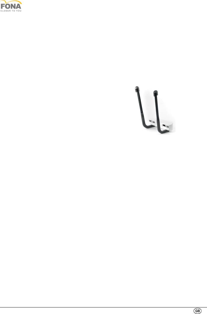
B Temporal resting bars
Temporal resting bars for use during patient positioning are optionally available.
The device is mounted with two screws on the back of the bite block /chin rest holder.
17
Technical Manuals
1.7. ASSEMBLING THE SYSTEM
WARNING. Do not change the installation sequence. Follow the sequence as described.
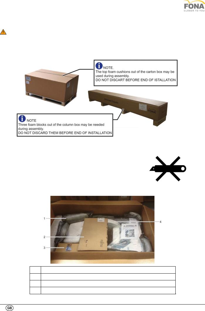
1.7.1. Unpacking
The system comes in two boxes: System body box and column box.
Opening the system box
•Cut the adhesive tape sealing the carton box and open the flaps.
•Cut the protecting sack with scissors paying attention not to scratch the internal items.
•Retrieve the packing list and check that listed items are received.
•Take the accessory box, open it, retrieve its packing list and verify that all the listed items are received.
•Retrieve the Installation Manual to be used for system assembly and installation.
WARNING. Avoid using the cutter not to damage the internal items
1Wall support
2PC
3Accessory Box
4System Body
18
FONA XPan 3D
Open the column box
•Carton box: remove top cover using a screwdriver to open
•Keep top cover close to the box with foam blocks upward
•Retrieve the packing list and check that listed items are present.
•Cut the protecting sack with scissors paying attention not to scratch the external surface of the column.
ATTENTION.
Do not use a cutter to open the protecting sack not to damage the external surface of the column.
ATTENTION.
Heavy weight duty. Installation must be done by at least two operators.
NOTE: A small plastic bag containing the spacers, bolts and washers for column installation is found inside the column box.
Taking out the column
1Foot
2Carriage Holding Plate
3Motor Cables
4Wall Support
•Extract the column from the box, the protective bag and the plastic bag, lay it down back side up on the foam blocks.
•Take the wall support and fix it to the column with the two M 8x20 screws, without tightening.
19
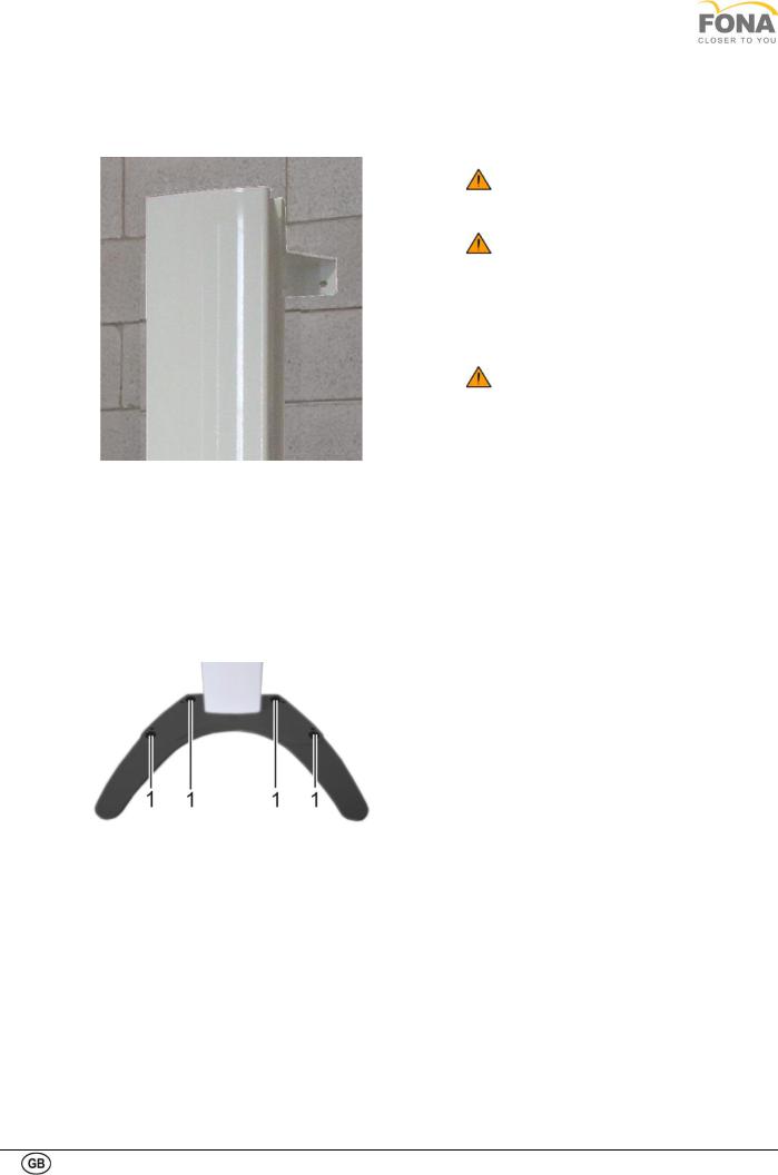
Technical Manuals
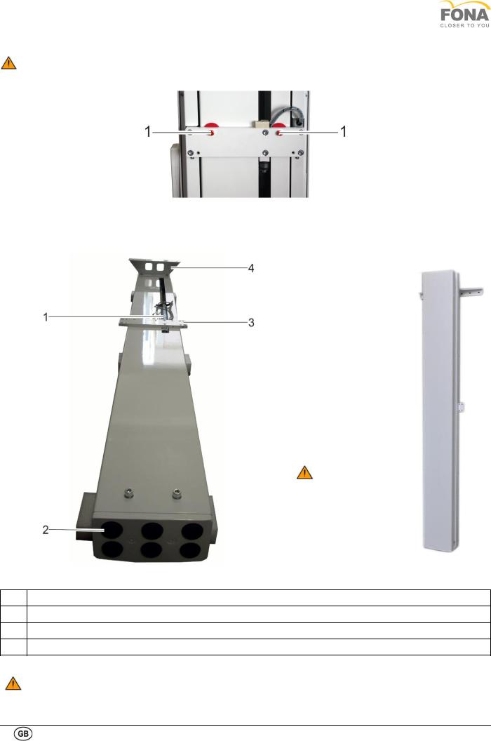
Make sure the carriage holding plate is blocked to the column with two safety bolts (1).
1.7.2. Preparing the column for wall mounting
In case of wall mounted configuration the column with the wall support can be brought close to the wall in the mounting position to mark holes for the anchors.
The wall holder has to be mounted at about 210 cm (82” 11/16) from the floor.
The room on the right side necessary for the operator to enter is of about 85 cm (34”). from mid plane of the column.
Loosen the safety bolts slightly (without removing them)
1Motor Cables
2Foot
3Carriage Holding Support and Safety Bolts
4Wall Support
INSUFFICIENT WALL OR HARDWARE STRENGHT MAY CAUSE THE WALL SUPPORT TO PULL OUT FROM THE WALL AND THE FULL SYSTEM TO FALL ON PAPATIENT OR OPERATOR CAUSING INJURIES
20
FONA XPan 3D
1.7.3. Preparing the column for floor mounting (Optional)
• Remove the foot to mount the self standing base. Then rotate the column to the front side.
• Fix the base to the column with 6 bolts M 10x25.
INSUFFICIENT WALL /FLOOR
HARDWARE STRENGHT MAY CAUSE
THE WALL /FLOOR HOLDER TO PULL
OUT AND THE FULL SYSTEM TO FALL
ON PATIENT OR OPERATOR CAUSING
INJURIES
1Level Adjustments
2Floor Securing Points
IF POSSIBLE, MOUNT ALSO THE WALL SUPPORT TO REDUCE VIBRATIONS DURING USE
21
Technical Manuals
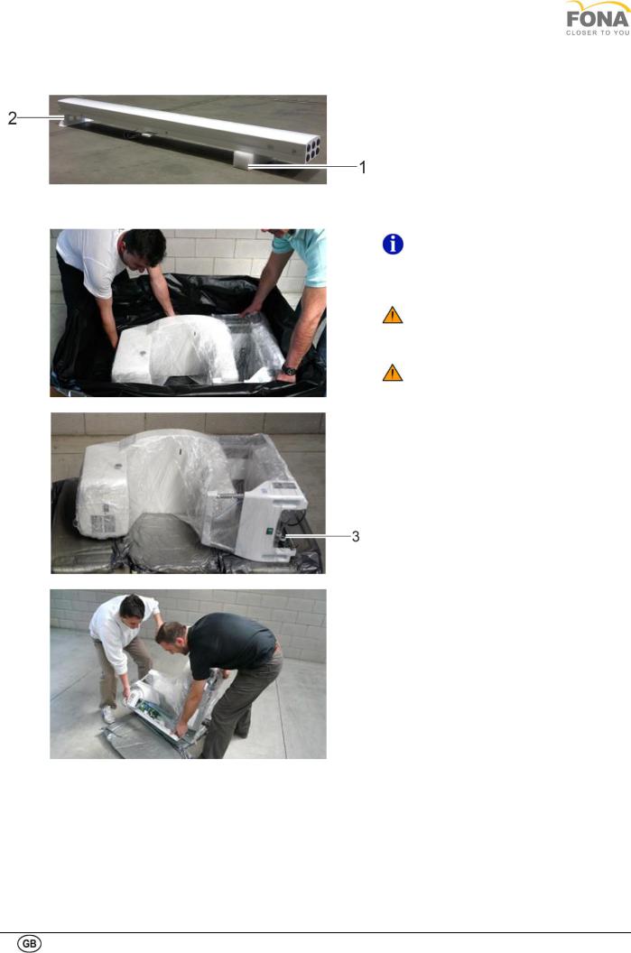
1.7.4. Mounting system body to the column
• Bring the column close to the mounting place.
• Take three foam blocks out of the column packaging and use them to sustain the column on the lower part.
• Lay down the column front part up, sustaining it on the wall support (2) on one side and on two foam blocks (1) on the other side.
NOTE. Do not remove the wrapping film blocking the rotating arm till to the end
of mechanical assembly when the unit is secured to the wall or to the floor.
ATTENTION. Remove the mirror cover before the installation of the rotating carriage onto the column.
ATTENTION. Heavy weight duty. Installation must be done by at least 2 operators.
• Place some cushions of foam on the floor close to the column to lay down first the cephalometric arm and then the carriage (body of the system).
• Take the carriage out of the carton box and place close to the column.
Two people involved:
• one holding the back of the carriage
• one holding the front part of the carriage
• Place the carriage close to the top part of the column
• Remove the wrapped film from the carriage only to have visibility of ball bearings (3).
• Position properly data cables and power cable in order to avoid inconvenience during insertion on column.
• Rotate the carriage on its back, ready to slide it on the column.
22
FONA XPan 3D
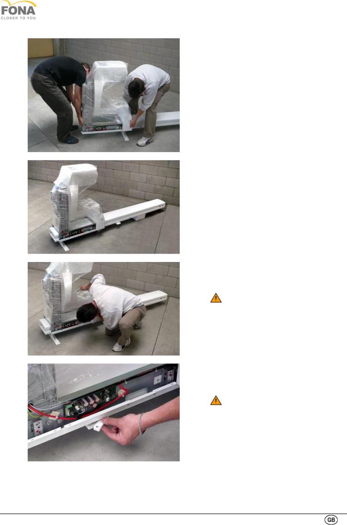
• Slide in the carriage carefully on the column paying attention not to scratch the paint or to damage ball bearings during carriage insertion.
• Push the body of the system in place to secure it to the carriage holding plate.
• If needed, loosen the safety bolts more to allow the carriage to reach the fixation points.
Do not remove the safety bolts before the system has been secured to the wall or to the floor.
• Secure the body of the system to the carriage holding plate with two bolts and one spacer at each side.
Leave the safety bolts partially loose but do not remove them before the system has been secured to the wall or to the floor.
23
Technical Manuals
1.7.5. Lifting and securing the system
Securing to the wall
Depending on the construction type of the wall, suitable wall plugs must be used. Wall plugs to be provided by the installer.
In case the wall is not in condition to withstand the indicated load, the adoption of reinforcing plate and connection with bolts through the wall can be considered, or the optional self standing base.
• Lift the system.
ATTENTION. The weight of the system pre-assembled is of 98 kg/216lb. Minimum two people are required to raise it.
• Move the system at small steps till against the wall.
• Secure the wall support to the wall without tightening.
• Assure the column is properly leveled correcting in case any left or right, forward or backward leaning.
• When leveling is fine, tighten the bolts both on the wall and on the column.
Securing to the floor
In case the self standing base is used, the same has to be bolted to the floor (1).
• Bring the unit in place and mark for anchors.
• Make holes and prepare the floor according to type of anchors used.
• Secure the self standing base to the floor
• Adjust the base for proper leveling.
• Tighten bolts.
• Mount the plastic cover over the self standing base
24
FONA XPan 3D
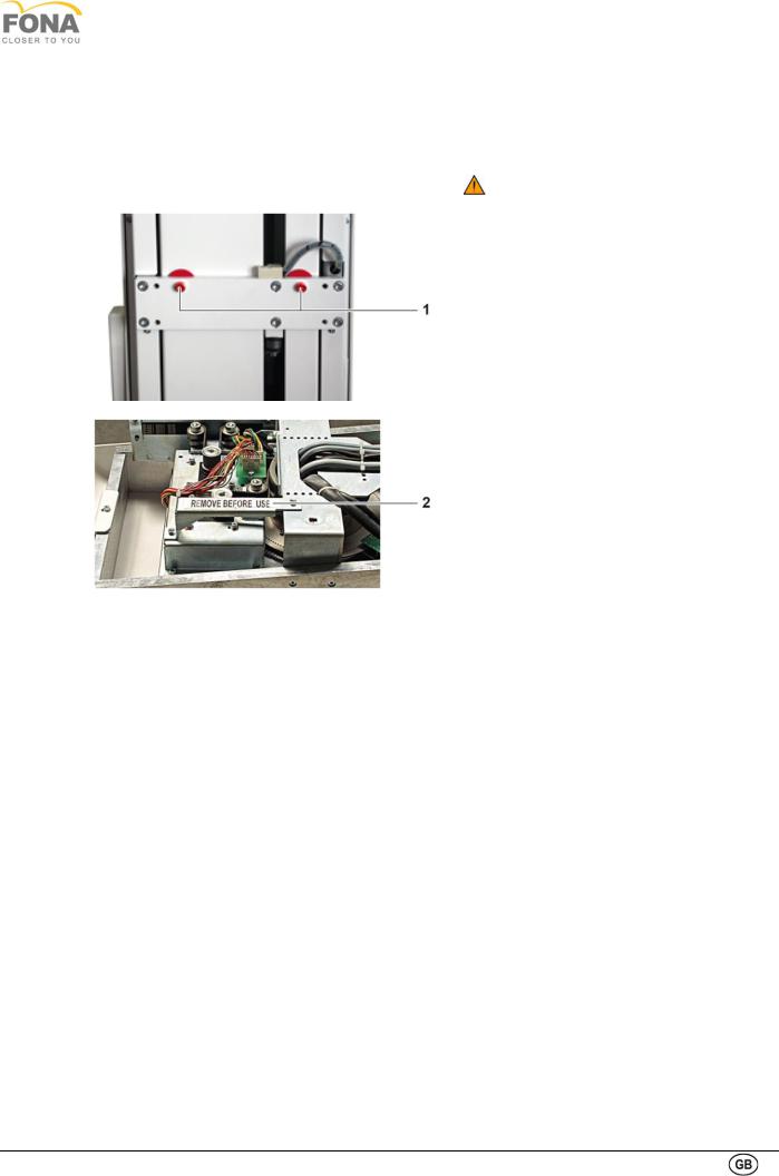
1.7.6. Removing safety bolts and transport bracket
The system is now vertical and secured to the wall or to the floor.
Before turning the system ON:
• Ensure the two safety bolts (1) on the back of the column and free the carriage holding plate
• Remove the wrapping foil all around.
• Remove the transport bracket (2) mounted on the top of the unit.
25

Technical Manuals
1.8. ELECTRICAL CONNECTIONS
1.8.1. Configuring the power supply unit
PLUG ON LEFT SIDE FOR 115 V PLUG ON RIGHT SIDE FOR 230 V
The system is delivered with voltage selector plug and primary fuses F501 (2) and FU303 not mounted.
The system must be configured to work either at 115 V or 230 V.
Remove the metal shield on the Power Supply Unit paying attention not to disconnect the cables of the buzzer and park it on the side.
115 V setting:
• Set voltage selector plug on left side
• Mount 3.15 AT fuse on fuse holder FU303
|
• Mount 16 AT fuse on fuse holder F501 |
|
230 V setting: |
|
• Set voltage selector plug on right side |
|
• Mount 1.6 AT fuse on fuse holder |
|
FU303 |
|
• Mount 8 AT fuse on fuse holder F501 |
|
Verify presence of fuses common fuses |
|
• FU304 rated 6.3 AF |
|
• FU305 rated 6.3 AF |
|
• FMOT 4 A fuse (1) |
LEFT SIDE |
RIGHT SIDE |
26
FONA XPan 3D
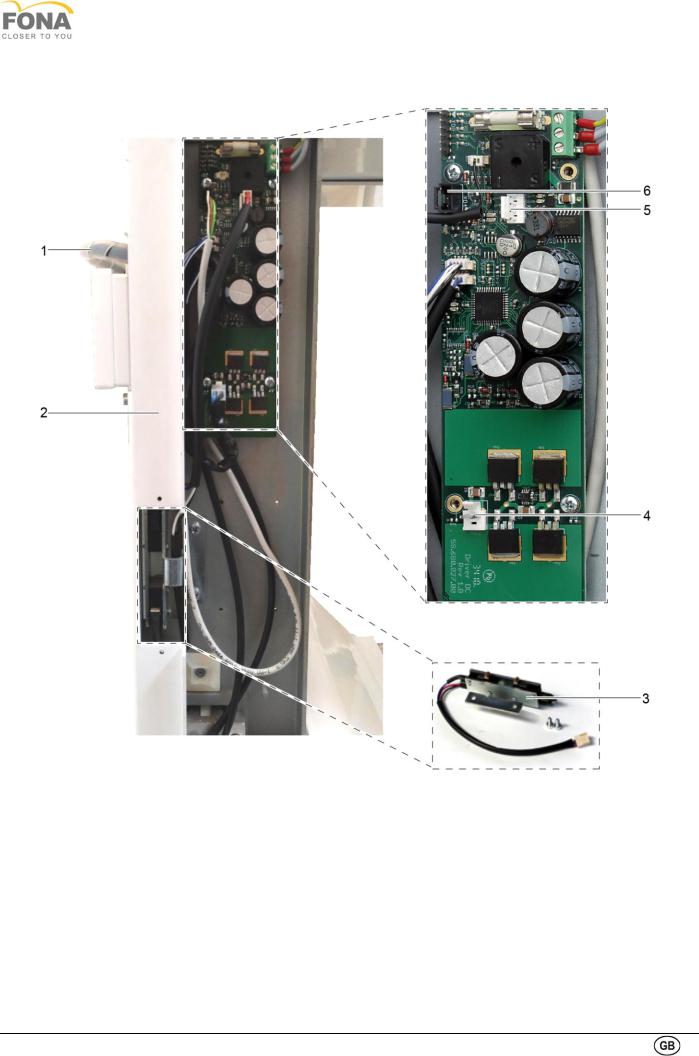
1.8.2. Connecting the motor for vertical movement
•Pass the motor cables (supply and encoder cables) (1) through the hole on the back of the white angular support
(2), on the right side of the unit.
•Remove the limit switches assembly cover.
•Retrieve the limit switches from the supplied items (3).
•Install the limit switches assembly.
•Verify the space between the column and the wheels of the limit switch is within 1mm and 3mm. If necessary, adjust the limit switch assembly accordingly. Further functional check will be done when the device will be powered.
•Apply the limit switch assembly cover.
•Connect the limit switches to XD7 (5).
•Connect the motor supply cable to XD2 (4).
•Connect the motor encoder cable to XD4 (6).
27
Technical Manuals
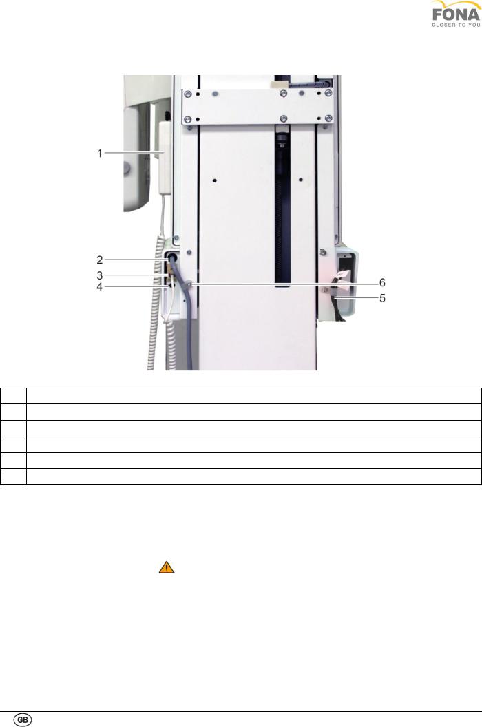
1.8.3. Connecting the hand-switch and other facilities
1X-Ray Hand Switch
2Mains Line Cable
3Connector Cable X-Ray Hand Switch
4Entry Point for Wires of External Lights and Door Contact
52 Ethernet CAT 5e Cables (Sensor & Unit)
6Strain Relief
On the back of the unit there are the entry points for necessary cables
.
•On the left side of the unit (right side on picture above) there is the slot for two different Ethernet cables (CAT.5e) which must be properly connected to the provided PC.
Attention! In case of replacement of the cable, use only 5E cables (or superior) shorter than 20m.
•On the right side of the unit (left side on picture above) use the entry points for the cables of door contact and external lights in case of applicability and connect the coiled cable of the X-ray hand-switch to the plug. The same connector is used for the extension cable of the kit for or remote mounting of the hand-switch.
28

FONA XPan 3D
1.8.4. Connecting the remote hand-switch option
The hand switch can alternatively be mounted remotely in case the unit is located in an X-ray room with proper window on the door to enable visual contact with the patient.
•Make sure that the distance between the device and the desired position of the remote hand-switch is less than the length of the provided 4 wire cable (10 m).
•Route the 4 wire cable inside the conduit in the wall (if existing) or by creating an external duct, without obstructing the normal walk of the operators. In this case path on the wall or on the edge of the floor is recommended.
•The 4 wire cable must enter in the wall behind the desired remote switch position, external respect to the treatment room.
•Remove the remote cover.
•Mount the plastic box in the remote position, by securing it on the wall with 4 screws.
•Connect the plug of the 4 wire cable to the hand switch plug on the back of the system (connector on the right side).
•Connect the 4 wire cable to the block into the metal box.
•Close the plastic box.
•Connect the coiled cord of the hand switch to the socket at bottom of the plastic box.
•A magnet is provided to hold the hand switch.
1Window for the Incoming 4 Wire Cable
2Connection Module 4 Wire Cable
3Socket for the Coiled Cord
4Screw Holder for the Cover
5Yellow Light
6X-ray Push Button
29
Technical Manuals
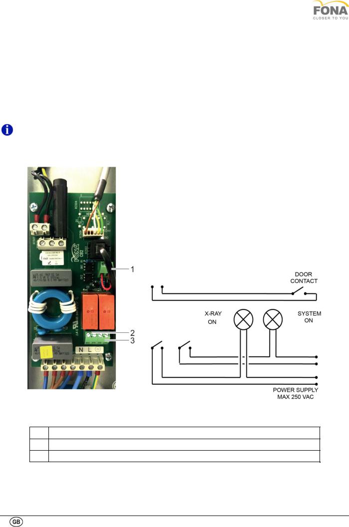
1.8.5. Connecting the external lights and door contact
The mains connection module (behind the mirror cover, right side of the unit) provides the contacts to enable the following safety conditions:
•The external light turns ON when irradiation is started. The two contacts on the left of the connector X1 are normally opened and they close when the radiation is enabled.
•The external light turns ON when the system is turned ON. The two contacts on the right of the connector X1 are normally opened and they close when the device is on.
•The irradiation is enabled if the door is closed. The unit is provided with a cable bridge already mounted on connector X2, which must stay in place if the door contact is not used, otherwise it must be removed to connect the door contact.
NOTE: The external safety lights must be powered externally with maximum 250 VAC.
1X2: Contacts for Door Switch
2X1: External Light X-Ray On
3X1: External Light System On
30
 Loading...