

Page 1
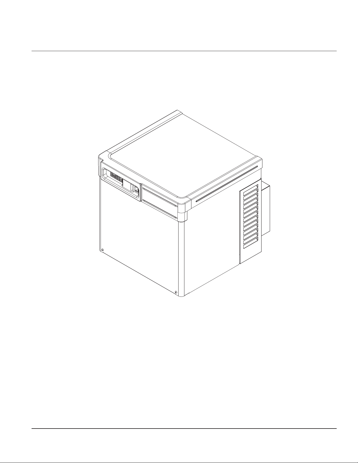
HC_1810R/N, HC_2110R/N, HM_1810R/N, HM_2110R/N
Horizon Elite™ Ice Machines (Remote Condensing)
User Guide
After Serial Number L60417
Please visit www.follettice.com/technicaldocuments
for the Operation and Service manual for your unit.
Welcome to Follett
Follett equipment enjoys a well-deserved reputation for excellent performance, long-term reliability and outstanding
after-the-sale support. To ensure that this equipment delivers that same degree of service, review this guide
carefully before you begin your installation.
Should you need technical help, please call our Technical Service group at (877) 612-5086 or (610) 252-7301.
Please have your model number, serial number and complete and detailed explanation of the problem when
contacting Technical Service.
Getting Started
After uncrating and removing all packing material, inspect the equipment for concealed shipping damage. All freight
is to be inspected upon delivery. If visible signs of damage exist, please refuse delivery or sign your delivery receipt
"damaged." Follett Customer Service must be notied within 48 hours. Wherever possible, please include detailed
photos of the damage with the original packaging so that we may start the freight claim process.
801 Church Lane • Easton, PA 18040, USA
Toll free (877) 612-5086 • +1 (610) 252-7301
www.follettice.com
Installation and Service Videos:
www.follettice.com/servicevideolibrary
01266550R02
Page 2
CAUTION
• Warranty does not cover exterior or outside installations.
• Moving parts. Do not operate with front cover removed.
• Hot parts. Do not operate with cover removed.
• To reduce risk of shock, disconnect power before servicing.
• Drain line must not be vented.
• Water supply must have particle ltration.
• Most ice machine cleaners contain citric or phosphoric acid, which can cause skin irritation. Read caution label
on product and follow instructions carefully.
• Ice is slippery. Maintain counters and oors around dispenser in a clean and ice-free condition.
• Ice is food. Follow recommended cleaning instructions to maintain cleanliness of delivered ice.
Specications
Electrical
Separate, dedicated circuit and equipment ground required.
Evaporator unit
Standard electrical: 115/60/1
Maximum fuse: 15A
Amperage: 5A
Condensing unit
1810 Single-Phase 1810 3-Phase 2110 Single-Phase 2110 3-Phase
Electrical 208-230V, 60Hz
Max Circuit HVACR breaker size 45A 25A 45A 30A
Min Circuit Ampacity 26.2A 15.7A 27.1A 19.9A
Evaporator plumbing
§ 3/8" OD push-in water inlet (connection inside machine) - 3/8" OD tubing required.
§ Water shut-off recommended within 10 feet (3 m).
§ Follett recommends installation of Follett water lter system (part# 00130286) in ice machine inlet water line.
2 HC_1810R/N, HC_2110R/N, HM_1810R/N, HM_2110R/N
Page 3
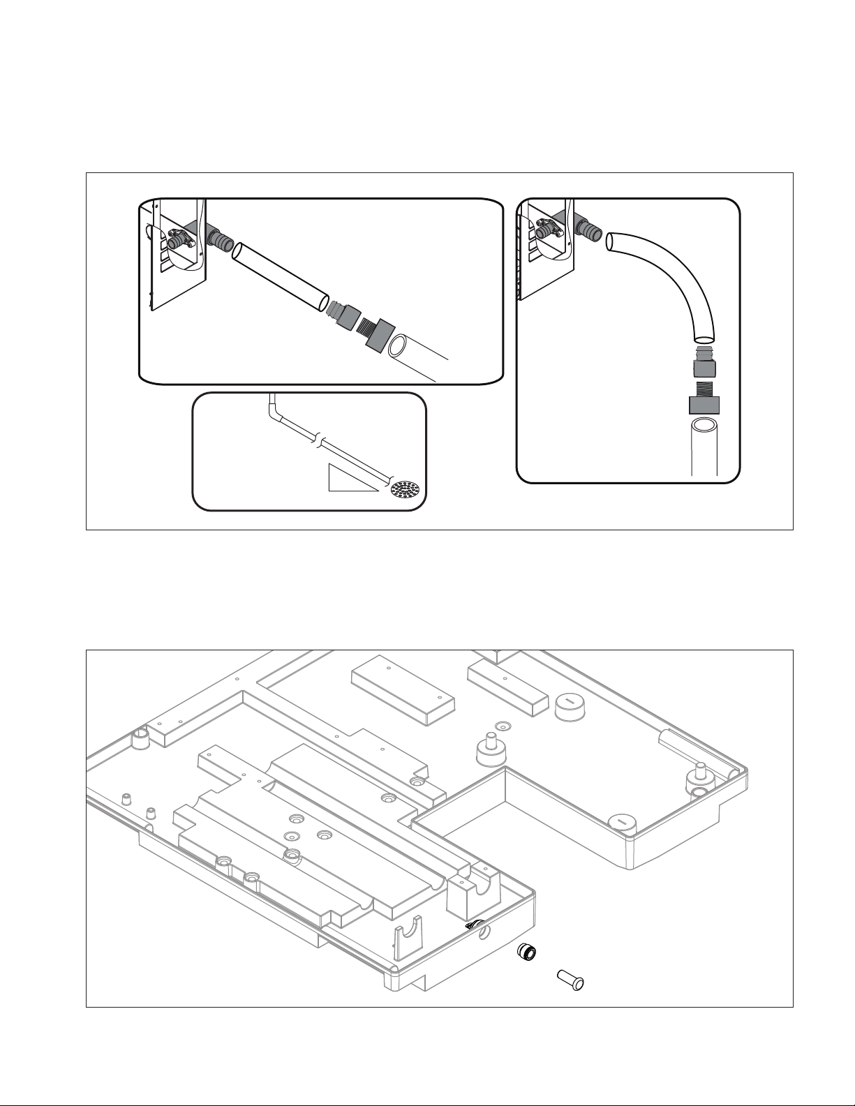
Flush drain plumbing
3/4" barb x 3/4" FPT
1" Stand pipe/Drain
2 ft. x 1" OD
silicone tubing
Minimum 8"
radius
3/4" MPT x 1" slip
1" PVC Drain
2 ft. x 1" OD
silicone tubing
3/4" MPT x 1" slip
3/4" barb x 3/4" FPT
1'
1/4" per foot
(6,4 mm per 0,3 m)
§ 3/4" MPT ush drain connection at the rear of the machine.
§ Drain must slope 1/4" inch per foot (6 mm per 30.4 cm).
§ Drain line should not be shared with any other piece of equipment.
§ Drain line cannot be reduced to a size smaller than 1 inch.
§ Drain should be piped without a vent.
Chassis drain plumbing
§ Plug must be removed from John Guest tting.
§ Route 3/8" drain tubing through knockout in back of docking station and insert fully into John Guest tting
connection at the rear of the machine chassis. Route other end of 3/8" drain tubing to drain.
§ Drain must slope 1/4" inch per foot (6 mm per 30.4 cm).
HC_1810R/N, HC_2110R/N, HM_1810R/N, HM_2110R/N 3
Page 4
Ambient
Evaporator unit
Air temperature 100 F/38 C max. 50 F/10 C min.
Water temperature 90 F/32 C max. 45 F/7 C min.
Water pressure 70 psi max. (483 kPa) 10 psi min. (69 kPa)
Condenser unit
Air temperature 120 F/49 C max. –20F/–29C min.
Refrigeration
§ 3/8" liquid line
§ 7/8" suction line
Note: Rack system installations require a capacity of 15,700 BTU/hr for 1810 machines and 18,200 BTU/hr for
2110 machines at 0 F (–18 C) evaporator temperature. Evaporator pressure regulator (not supplied) is
required.
Weight
Evaporator unit:
1810: 157 lbs (71.2 kg)
2110: 165 lbs (74.8 kg)
Condensing unit: 305 lbs (138.3 kg)
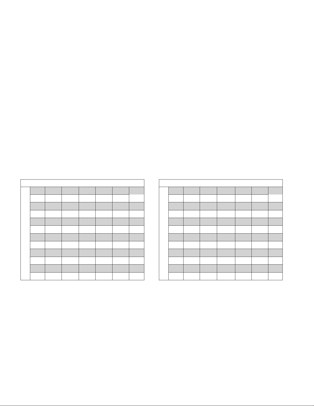
Ice production
1810 ice machine capacity/24 hrs.
Ambient Air Temperature F/C
F 60 70 80 90 100
C 16 21 27 32 38
50 1859 1784 1685 1616 1500 lbs
10 843 809 764 733 680 kg
60 1723 1684 1578 1563 1409 lbs
16 782 764 716 709 639 kg
70 1620 1594 1514 1420 1319 lbs
21 734 723 687 644 598 kg
80 1550 1487 1485 1351 1299 lbs
27 703 6 74 674 613 589 kg
90 1471 1435 1370 1285 1207 lbs
Evap Potable Water Temperature F/C
32 667 651 621 583 547 kg
2110 ice machine capacity/24 hrs.
Ambient Air Temperature F/C
F 60 70 80 90 100
C 16 21 27 32 38
50 2039 2039 1934 1825 1703 lbs
10 925 925 877 828 772 kg
60 1943 1888 1878 1710 1584 lbs
16 881 856 852 772 718 kg
70 1833 1781 1789 1634 1489 lbs
21 831 808 811 741 675 kg
80 1754 1686 1643 1535 1426 lbs
27 796 765 745 696 647 kg
90 1650 1603 1577 1457 1395 lbs
Evap Potable Water Temperature F/C
32 748 727 715 661 633 kg
4 HC_1810R/N, HC_2110R/N, HM_1810R/N, HM_2110R/N
Page 5
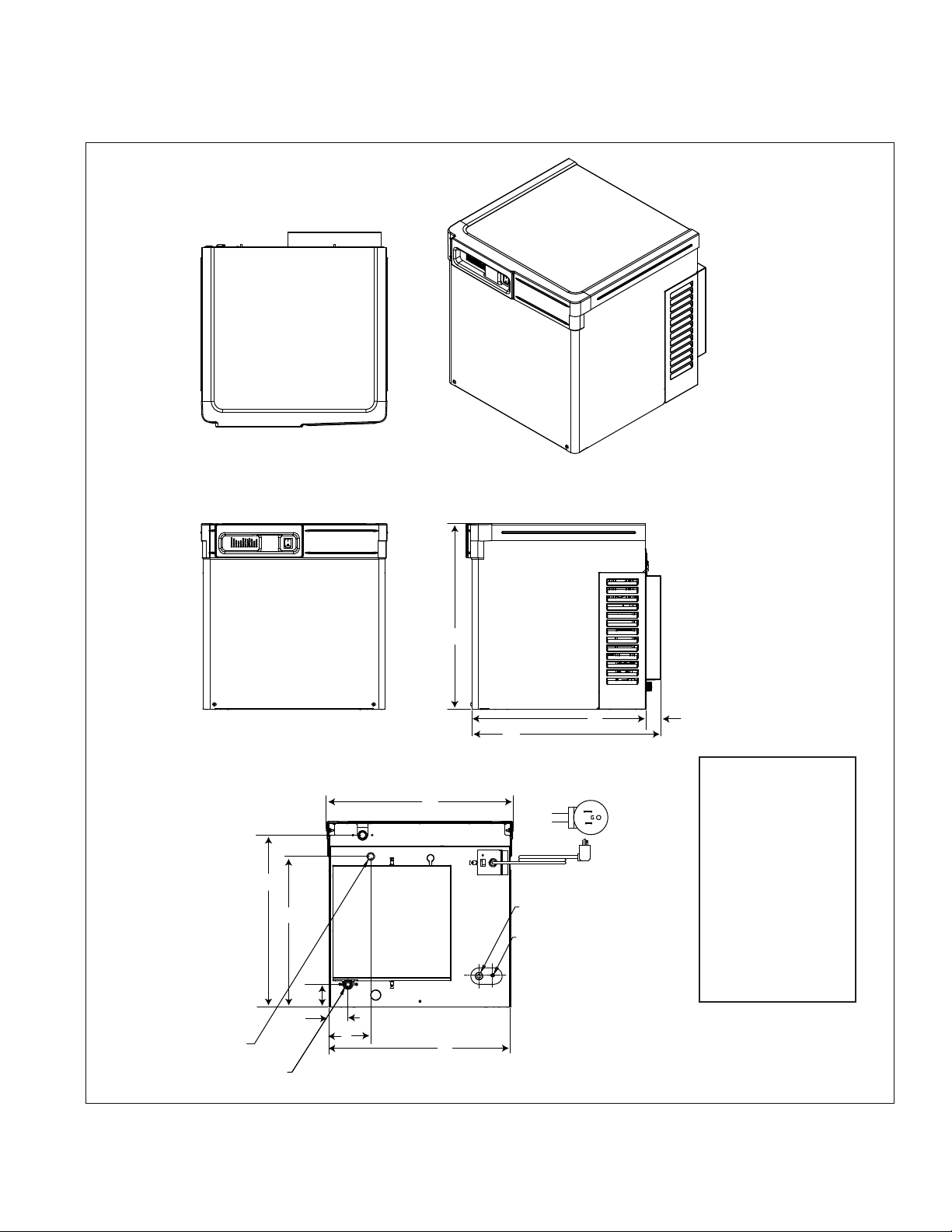
Dimensions and clearances
§ Entire front of ice machine must be clear of obstructions/connections to allow removal.
§ 1" (26mm) clearance above ice machine for service.
§ 1" (26mm) minimum clearance on sides.
TOP VIEW
3/8" OD PUSH-IN
WATER INLET
3/4" BARB DRAIN
FRONT VIEW
E
F
G
H
I
A
K
J
BACK VIEW
B
C
NEMA 5-15
RIGHT ANGLE
7/8" SUCTION LINE
3/8" LIQUID LINE
D
A 22.5" (57.1 cm)
B 21.1" (53.6 cm)
C 22.9" (58.2 cm)
D 1. 8 " (4.5 cm)
E 20.8" (52.9 cm)
F 18.3" (46.4 cm)
G 2.7" (6.9 cm)
H 2.3" (15.3 cm)
I 5.0" (12.8 cm)
J 22.0" (55.9 cm)
K 22.7" (57.6 cm)
HC_1810R/N, HC_2110R/N, HM_1810R/N, HM_2110R/N 5
Page 6
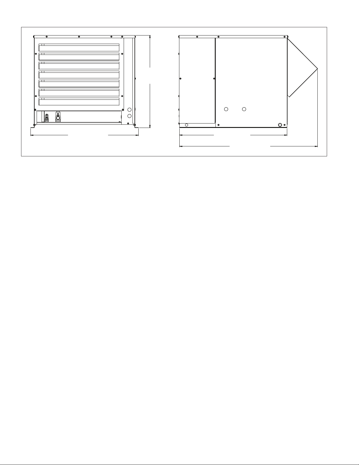
Condensing unit
25.75"
(65.3 cm)
30" (76.2 cm)
29.9" (76 cm)
38.5" (97.5 cm)
6 HC_1810R/N, HC_2110R/N, HM_1810R/N, HM_2110R/N
Page 7
Operation
Cleaning/sanitizing and preventive maintenance (all models)
Note: Do not use bleach to sanitize or clean the icemaker.
Preventive maintenance
Periodic cleaning of Follett’s icemaker system is required to ensure peak performance and delivery of clean,
sanitary ice. The recommended cleaning procedures that follow should be performed at least as frequently as
recommended, and more often if environmental conditions dictate.
Cleaning of the condenser can usually be performed by facility personnel. Cleaning of the icemaker system,
in most cases, should be performed by your facility’s maintenance staff or a Follett authorized service agent.
Regardless of who performs the cleaning, it is the operator’s responsibility to see that this cleaning is performed
according to the schedule below. Service problems resulting from lack of preventive maintenance will not be
covered under the Follett warranty.
Weekly exterior care
The exterior may be cleaned with a stainless cleaner such as 3M Stainless Steel Cleaner & Polish or equivalent.
Monthly condenser cleaning (air-cooled icemaker only)
1. Use a vacuum cleaner or stiff brush to carefully clean condenser coils of air-cooled icemakers to ensure
optimal performance.
2. When reinstalling counter panels in front of remote icemakers, be sure that ventilation louvers line up with
condenser air duct.
Semi-annual evaporator cleaning (every 6 months)
WARNING
• Wear rubber gloves and safety goggles (and/or face shield) when handling ice machine cleaner or sanitizer.
CAUTION
• Use only Follett approved SafeCLEAN Plus™ cleaning solution.
• DO NOT USE BLEACH.
• It is a violation of federal law to use these solutions in a manner inconsistent with their labeling.
• Read and understand all labels printed on packaging before use.
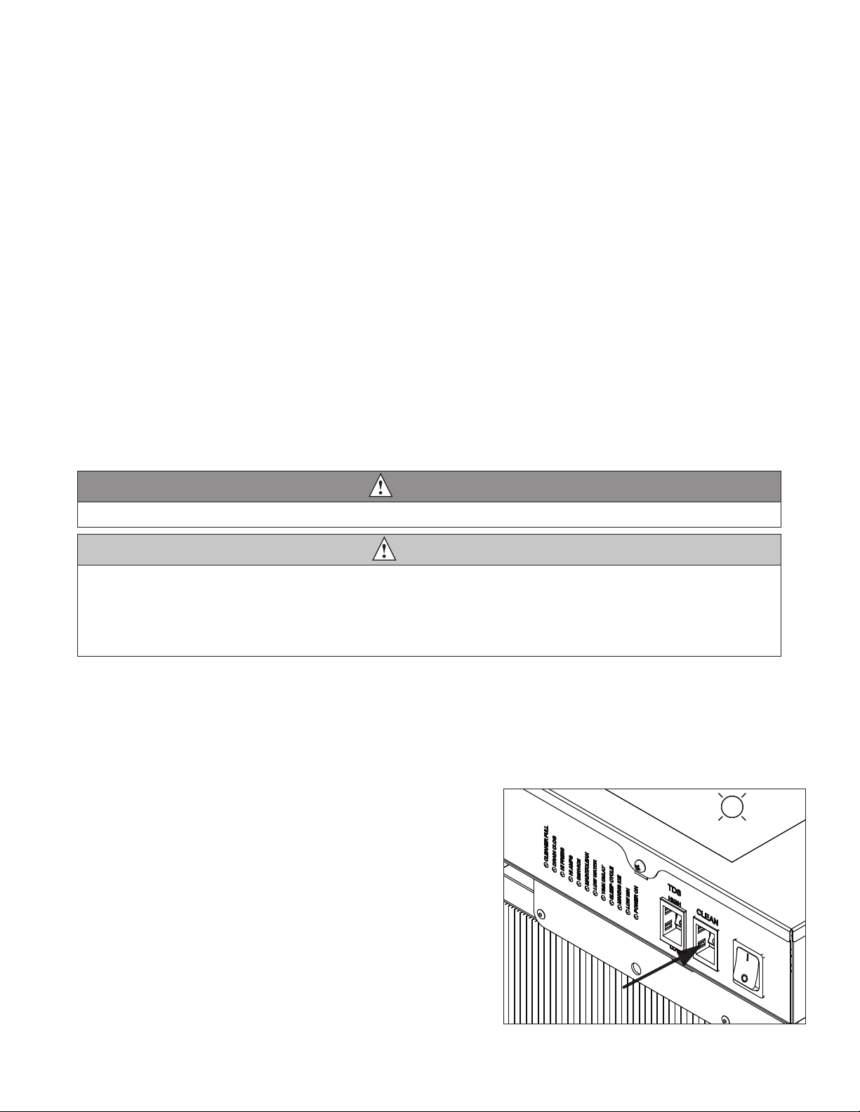
Note: Complete procedure for cleaning an sanitizing MUST be followed. Ice must be collected for 10minutes
before putting ice machine back into service.
Fig. 1
1. Press the CLEAN button. The machine will drain. The
auger will run for a short time and then stop. Wait for
the LOW WATER light to come on.
LO WATER
HC_1810R/N, HC_2110R/N, HM_1810R/N, HM_2110R/N 7
Page 8
2. Follow the directions on the SafeCLEAN Plus
packaging to mix 1 gal. (3.8 L) of Follett SafeCLEAN
Plus solution. Use 100 F (38 C) water.
3. Using a 1 quart (1L) container, slowly ll cleaning cup
until CLEANER FULL light comes on. Do not overll.
4. Place one SaniSponge™ cleaning sponge in
remaining sanitizing and cleaning solution and retain
for Step 9.
Note: Do not use bleach to sanitize or clean the icemaker.
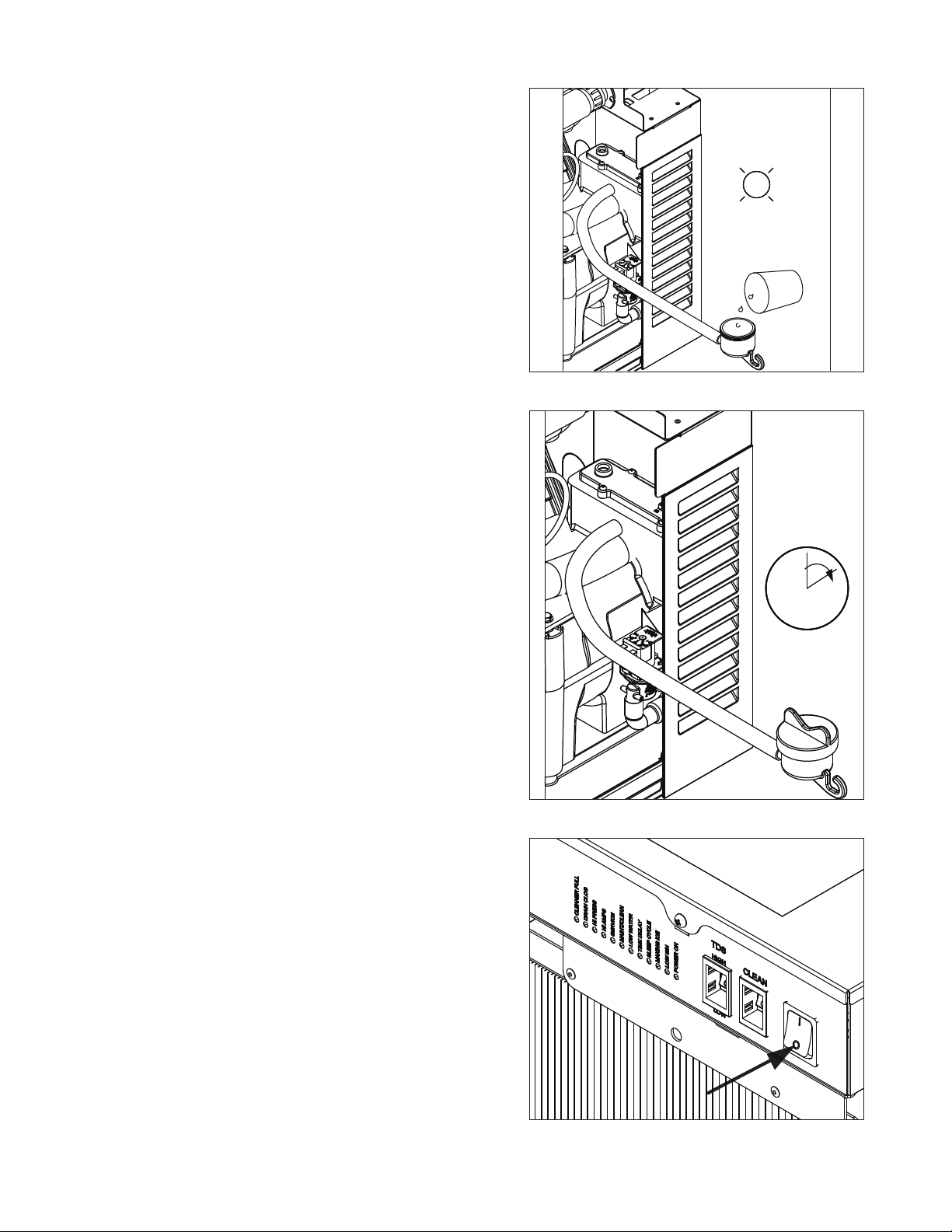
5. Replace cover on cleaner cup. Machine will clean,
then ush 3 times in approximately 15 minutes. Wait
until machine restarts.
Fig. 2
CLEANER FULL
Fig. 3
6. To clean/sanitize ice transport tube – Press power
switch OFF
15
Fig. 4
8 HC_1810R/N, HC_2110R/N, HM_1810R/N, HM_2110R/N
Page 9
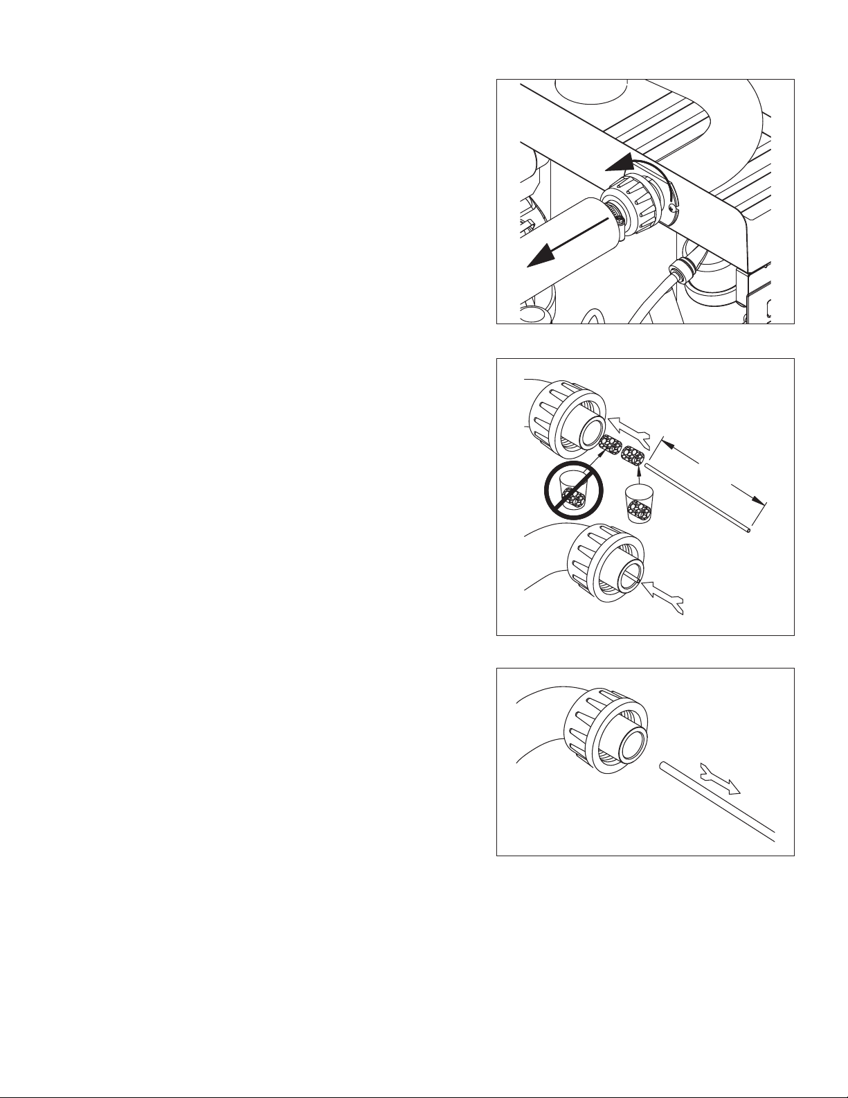
7. Disconnect coupling as shown.
8. Using disposable foodservice grade gloves, insert dry
SaniSponge cleaning sponge.
9. Insert Sani-Sponge soaked in SafeClean Plus (from
Step 4).
10. Push both SaniSponge cleaning sponges down ice
transport tube with supplied pusher tube.
Fig. 5
Fig. 6
1
16"
(407 mm)
11. Remove and discard 16 inch (407 mm) pusher tube.
2
3
Fig. 7
HC_1810R/N, HC_2110R/N, HM_1810R/N, HM_2110R/N 9
Page 10
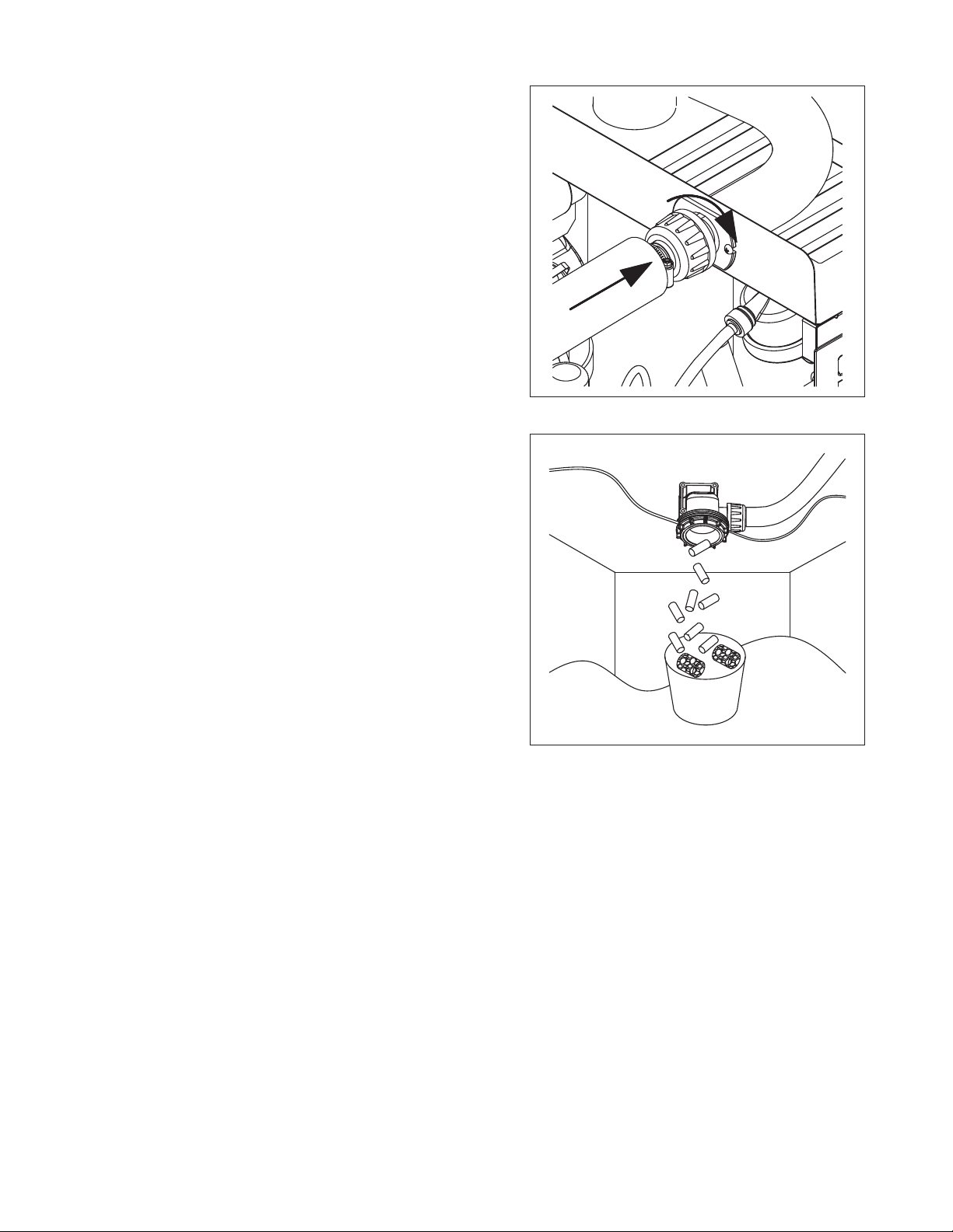
12. Reconnect coupling. Press power switch ON. Ice
pushes SaniSponge cleaning sponges through ice
transport tube.
13. Place a sanitary (2 gal. or larger) container in bin or
dispenser to collect SaniSponge cleaning sponges
and ice for 10 minutes.
14. Collect 5.5 lbs (3 kg) of ice from unit. Discard ice and
SaniSponge cleaning sponges.
Fig. 8
Fig. 9
10 HC_1810R/N, HC_2110R/N, HM_1810R/N, HM_2110R/N
Page 11
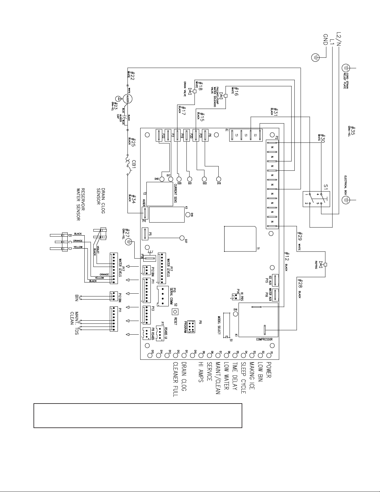
Wiring diagram, evaporator unit
Gearmotor data
Gearmotor current 4.0A @ 115 V
Gearmotor torque-out (high amp) trip point: 7.0A
HC_1810R/N, HC_2110R/N, HM_1810R/N, HM_2110R/N 11
Page 12
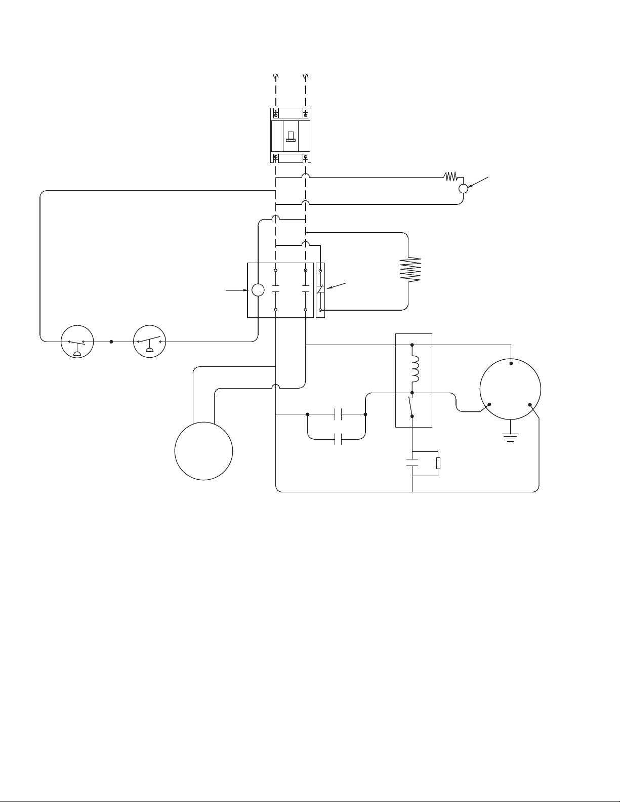
Single-phase condensing unit wiring diagram
(Danfoss MTZ36-1AV) MOP = 45; MCA = 26.2
(Danfoss MTZ44-1AV) MOP = 45; MCA = 27.1
CIRCUIT BREAKER (by others)
45A for MTZ36-1AV
45A for MTZ44-1AV
NOTE: MAKE CONNECTIONS AT
CONTACTOR LUGS
CC
208-230V/1/60Hz
C
AR
HC
HIGH LIMIT 80F
PTC
CCH
Start Relay
LPC
HPC
CONDENSER
FAN
MOTOR
RUN 1
RUN 2
μF START
5
2
1
15 kΩ-1W
C
COMPRESSOR
S
R
12 HC_1810R/N, HC_2110R/N, HM_1810R/N, HM_2110R/N
Page 13
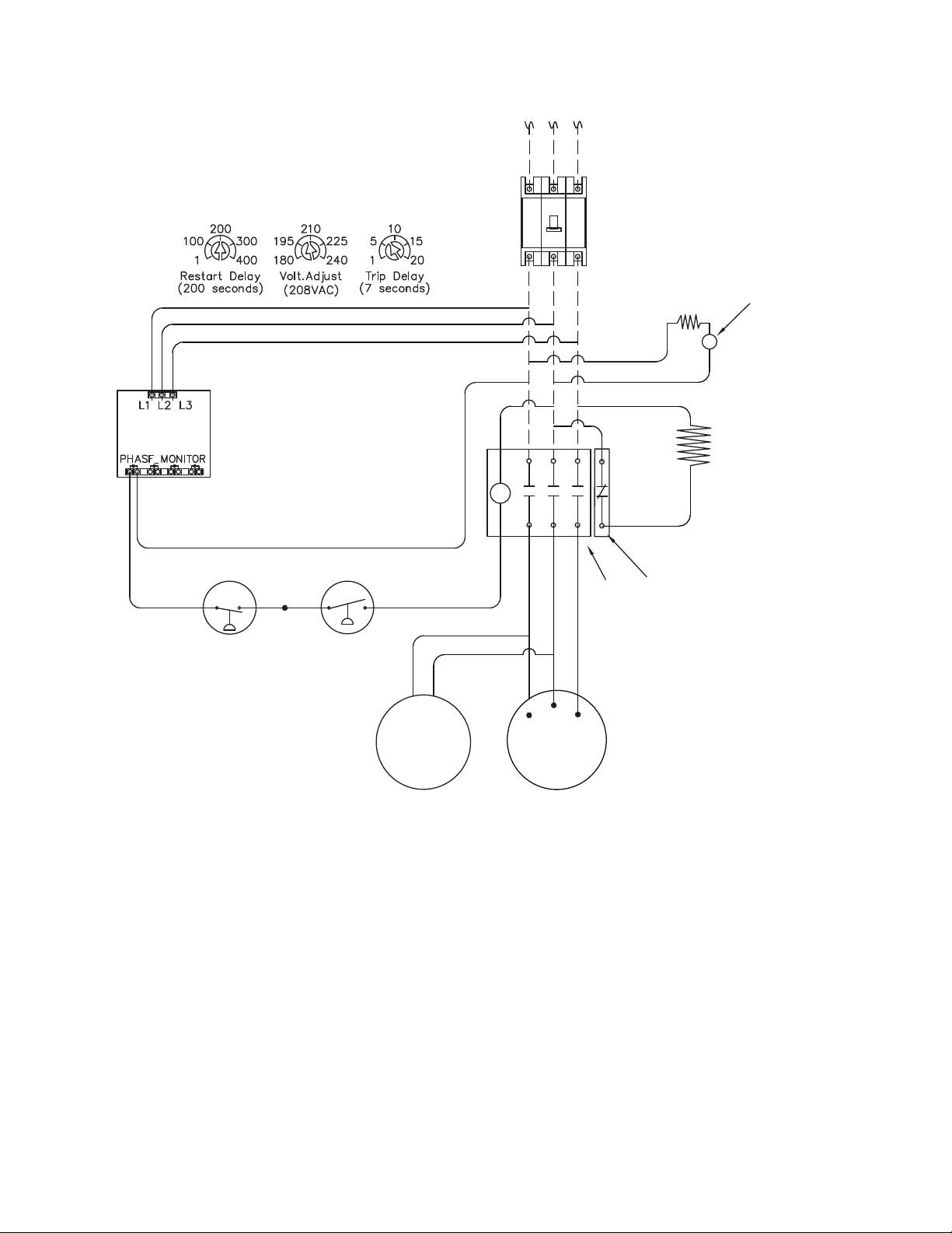
3-phase condensing unit wiring diagram
(Danfoss MTZ36-3AV) MOP = 25; MCA = 15.7
(Danfoss MTZ44-3AV) MOP = 30; MCA = 19.9
208-230V/3/60Hz
PHASE MONITOR
NOTE: MAKE CONNECTIONS
AT CONTACTOR LUGS
LPC
HPC
CIRCUIT BREAKER (by others)
25A for MTZ36-3AV
30A for MTZ44-3AV
HC
HIGH LIMIT 80F
PTC
CCH
C
CC
AR
CONDENSER
FAN
MOTOR
T2
T1
COMPRESSOR
T3
HC_1810R/N, HC_2110R/N, HM_1810R/N, HM_2110R/N 13
Page 14
Refrigeration system
1810 - Operating Pressure (Discharge PSIG/Suction PSIG)
Water Temperature F/C
F 50 60 70 80 90
C 10 16 21 27 32
60
182/27 182/27 182/27 182/27 183/27
16
70
188/28 188/28 188/28 188/27 188/27
21
80
218/30 218/30 218/30 218/30 219/30
27
90
249/32 249/32 249/32 249/32 249/32
32
100
282/34 282/34 282/34 282/34 282/34
38
Ambient Outdoor Temperature F/C
2110 - Operating Pressure (Discharge PSIG/Suction PSIG)
Water Temperature F/C
F 50 60 70 80 90
C 10 16 21 27 32
60
189/28 188/28 189/28 188/27 186/27
16
70
192/28 191/28 192/28 192/28 191/28
21
80
220/29 219/30 219/30 219/31 220/31
27
90
252/33 252/33 252/33 252/33 252/33
32
100
385/35 385/35 384/35 384/35 385/34
38
Ambient Outdoor Temperature F/C
14 HC_1810R/N, HC_2110R/N, HM_1810R/N, HM_2110R/N
Page 15
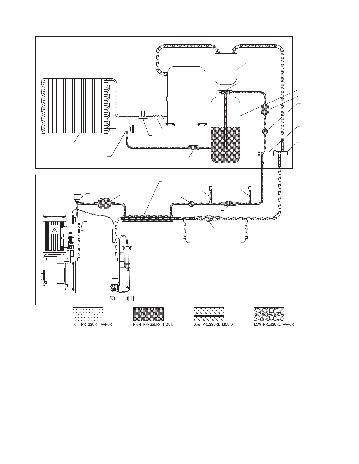
Refrigeration system diagram
CONDENSER UNIT
CONDENSER
HEAD CONTROL VALVE
COMPRESSOR
CHECK VALVE
HIGH PRESSURE SWITCH
CHECK VALVE
SUCTION
ACCUMULATOR
HIGH SIDE
SERVICE VALVE
W/ SERVICE PORT
RECEIVER
FILTER-DRIER
SIGHT GLASS
HIGH SIDE
SERVICE VALVE
W/ SERVICE PORT
LOW SIDE
SERVICE VALVE
W/ SERVICE PORT
EVAPORATOR UNIT
SOLENOID VALVE
THERMOSTATIC
EXPANSION
VALVE
FILTER
HEAT EXCHANGER
SIGHT GLASS
HIGH SIDE
SERVICE PORT
LOW SIDE
PORT
SERVICE PORT
HIGH SIDE
COUPLING
HIGH SIDE
LOW SIDE
COUPLING
LOW SIDE
PORT
HC_1810R/N, HC_2110R/N, HM_1810R/N, HM_2110R/N 15
Page 16
Refrigeration charge
All service on refrigeration systems must be performed in accordance with all federal, state and local laws. It is the
responsibility of the technician to ensure that these requirements are met. Recharging ice machine to other than
factory specications will void the warranty.
Attention: Unit must be charged by weight, not by clear sight glass.
R404A ice machine charge specications for 1810/2110 models with line
runs of 0 to 75 ft. (0 m to 22.8 m)
Total charge 14.5 lbs (6.57 kg)
Condensing unit holding charge 0.5 lbs (0.23 kg)
Charge at installation 14 lbs (6.35 kg)
Note: Condensing unit shipped with 0.5 lb of R404A charge.
Refrigerant replacement requirements
1. Non-contaminated refrigerant removed from any Follett refrigeration system can be recycled and returned to
the same system after completing repairs. Recycled refrigerant must be stored in a clean, approved storage
container. If additional refrigerant is required, virgin or reclaimed refrigerant that meets ARI standard 700-88
must be used.
2. In the event of system contamination (for example, a compressor burn out, refrigerant leak, presence of
non-condensibles or moisture), the system must be repaired, evacuated and recharged using virgin or
reclaimed refrigerant that meets ARI standard 700-88.
3. Follett LLC does not approve of recovered refrigerants. Improper refrigeration servicing procedures will void
the factory warranty.
Evacuation
Evacuate the system to a level of 500 microns. When the 500 micron level is reached, close all valves. Allow the
system to sit for approximately 20 minutes. During this period the system pressure should not rise. If the system
pressure rises and stabilizes there is moisture in the system and further evacuation is needed. If the pressure
continues to rise check the system for leaks.
Ambients Minimum Maximum
1
Air temperature
Water temperature
1
Ambient air temperature is measured at the air-cooled condenser coil inlet.
2
Ambient water temperature is measured in the ice machine water reservoir.
50 F/10 C 100 F/37.8 C
2
45 F/7 C 90 F/32.2 C
Ice capacity test
Ice machine production capacity can only be determined by weighing ice produced in a specic time period.
1. Replace all panels on ice machine.
2. Run ice machine for at least 15 minutes.
3. Weigh and record weight of container used to catch ice.
4. Catch ice for 15 or 20 minutes.
5. Weigh harvested ice and record total weight.
6. Subtract weight of container from total weight.
7. Convert fractions of pounds to decimal equivalents (ex. 6 lbs 8oz = 6.5 lbs).
8. Calculate production using following formula:
1440 min. x wt. of ice produced
Total test time in minutes
Production capacity/24 hr.
=
9. Calculated amount per 24 hours should be checked against rated capacity for same ambient and water
temperatures in Ice Production Tables.
16 HC_1810R/N, HC_2110R/N, HM_1810R/N, HM_2110R/N
Page 17
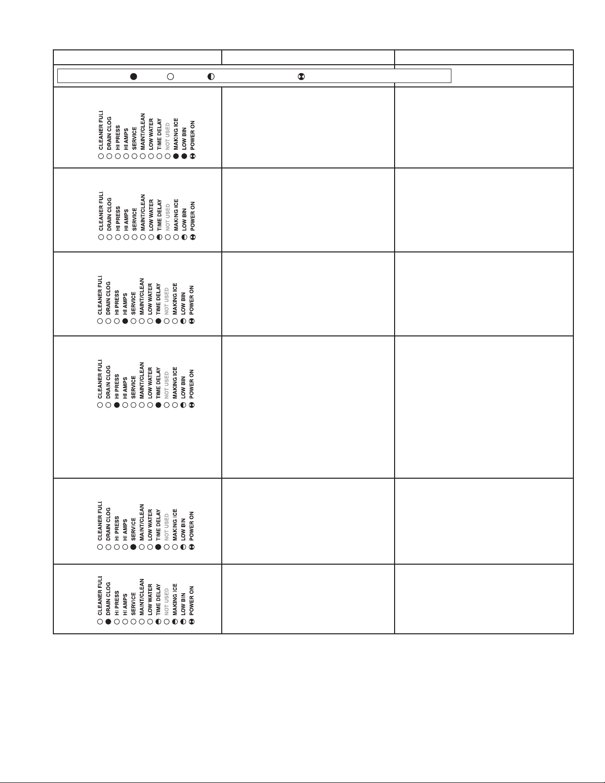
Troubleshooting
Ice machine disposition Possible causes Corrective action
Legend:
1. Ice machine is in running
condition but not making ice.
.
2. Machine in TIME DELAY without full
bin.
3. Ice machine is not making ice.
HI AMPS.
.
4. Ice machine is not making ice.
HI PRESSURE.
.
5. Ice machine is not making ice.
SERVICE.
OFFON
FLASHINGON or OFF
1. Defective compressor.
2. Defective start relay.
3. Defective start capacitor.
4. Defective run capacitor.
5. Defective main contactor.
6. No output from PC board.
1. Ice jamming due to improperly
installed transport tube causing a false
shuttle.
2. Shuttle stuck in up position.
3. Damaged or improperly installed
thermostat (open).
4. Transport tube backed-out of coupling.
1. Poor water quality causing ice to jam
auger.
2. Damaged shuttle mechanism.
3. Intermittent drive output from
PC board. Evaporator will freeze
causing a HI AMPS error.
4. Gearmotor is unplugged.
1. High ambient temperatures
>100 F (38 C).
2. Poor ventilation or air recirculation.
3. Clogged condenser (air-cooled).
4. No water ow through condenser
(water-cooled).
5. Fan not working properly. No
air ow.
• Blocked fan blades
• No fan output from PC board
• Faulty fan motor
1. Internal water leak touching chassis
sensor.
1. Replace compressor.
2. Replace start relay.
3. Replace start capacitor.
4. Replace run capacitor.
5. Replace main contactor.
6. Replace PC board.
1. Correct transport tube routing.
2. Repair or replace shuttle mechanism.
3. Replace or reposition thermostat.
4. Correct coupling installation.
1. Clean ice machine. Increase
ushing frequency. Position TDS switch
to High TDS setting.
2. Replace or repair shuttle
mechanism.
3. Replace PC board.
4. Plug in gearmotor.
1. Air condition area to below 100F
(38 C).
2. Reposition ice machine or properly
ventilate. Prevent ice machine exhaust
from recirculating.
3. Clean condenser grille (air-cooled).
4. Restore water ow to condenser.
5. Correct air ow.
• Remove any blockage from fan
blades
• Replace PC board
• Replace fan motor
1. Identify and repair leak. Clean/dry
chassis and sensors and restart
machine.
.
6. Drain clog.
.
1. Improper ow in drain system. 1. Correct/clean drain system.
HC_1810R/N, HC_2110R/N, HM_1810R/N, HM_2110R/N 17
Page 18
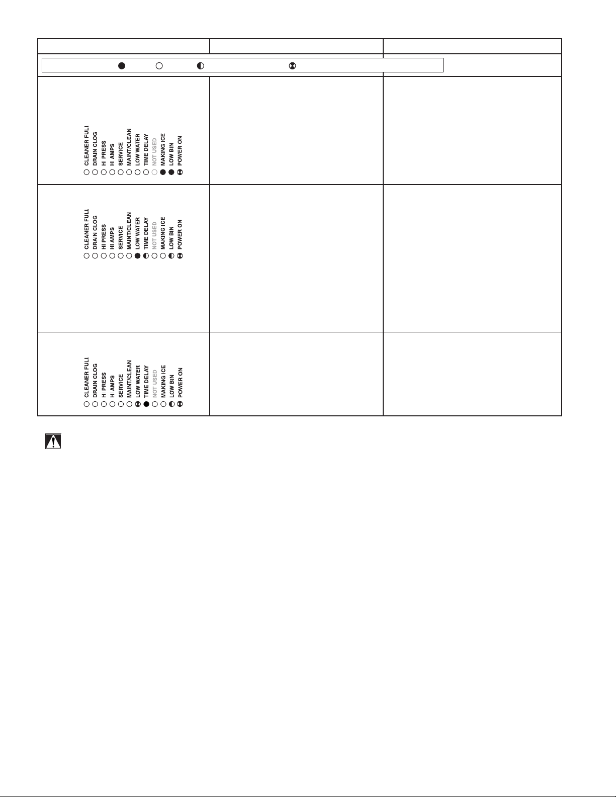
Ice machine disposition Possible causes Corrective action
Legend:
OFFON
7. Ice machine is making ice.
Excessive water in bin or
coming into bin from transport
tube.
8. Ice machine is not making ice.
Lo water.
9. Blinking Lo water, power, time
delay.
FLASHINGON or OFF
1. Failed water sensors. Processor
assumes there is no water when
there is water.
2. Blocked reservoir vent.
3. Defective water feed solenoid
valve. Stuck in open position.
1. Water supply is insufficient.
2. Low water pressure.
3. Defective water feed solenoid
valve. Stuck in closed position.
4. No water feed output from
PC board.
5. Plugged screen on inlet side of ll
solenoid.
6. Plugged check valve.
Machine did not see water
consumption while trying to make
ice.
1. Lack of refrigeration/low
refrigerant charge/leak.
2. Debris shorting reservoir probes.
1. Clean or replace water probe
assembly. Check wiring
connections.
2. Clean or replace vent tubes.
3. Replace water feed solenoid
valve.
1. Restore water supply and check
water lters. If evaporator was
completely empty the reset button
may have to be pressed to restart
the ice machine.
2. Ice machine will eventually start
when water reaches normal lo
level.
3. Replace water feed solenoid valve.
4. Replace PC board.
5. Remove and clean screen.
6. Remove and clean.
1. Verify refrigerant pressures,
compressor running, sight glass
clear.
2. Clean probes and reservoir of
debris.
ATTENTION!
To prevent circuit breaker overload, wait 5 minutes before restarting
this unit. This allows the compressor to equalize and the evaporator
to thaw.
18 HC_1810R/N, HC_2110R/N, HM_1810R/N, HM_2110R/N
Page 19

HC_1810R/N, HC_2110R/N, HM_1810R/N, HM_2110R/N 19
Page 20

Warranty Registration and Equipment Evaluation
Thank you for purchasing Follett equipment. Our goal is to earn your complete satisfaction by delivering high-value
products and services backed by outstanding customer and technical support.
Please review the installation instructions thoroughly. It is important that the installation be performed to factory
specications so your equipment operates at its maximum efficiency.
Follett LLC will not be liable for any consequential damages, expenses, connecting or disconnecting charges, or
any losses resulting from a defect of the machine. For full warranty details, visit our website www.follettice.com/
productwarranties.
Registering your equipments helps Follett track your equipment's service history should you need to contact us for
technical support, and your feedback helps us improve our products and services. Please visit www.follettice.com/
support to complete the Warranty Registration form.
Should you have any questions, please contact Follett's technical support group at (877) 612-5086 or
(610) 252-7301 and we will be happy to assist you.
Harmony, Ice Manager, Micro Chewblet, SafeCLEAN Plus, SaniSponge and Vision are trademarks of Follett LLC.
Chewblet, RIDE and Follett are registered trademarks of Follett LLC, registered in the US.
801 Church Lane • Easton, PA 18040, USA
Toll free (877) 612-5086 • +1 (610) 252-7301
www.follettice.com
01266550R02
© Follett LLC 5/20
 Loading...