

Page 1
110 Series
Ice and Water Dispensers
Operation, Service and Parts Manual
Service Number 5024400 and Above
207934R00
801 Church Lane • PO Box D, Easton, PA 18044
Toll free (800) 523-9361 • (888) 2-FOLLETT
(610) 252-7301 • Fax (610) 250-0696 • www.follettice.com
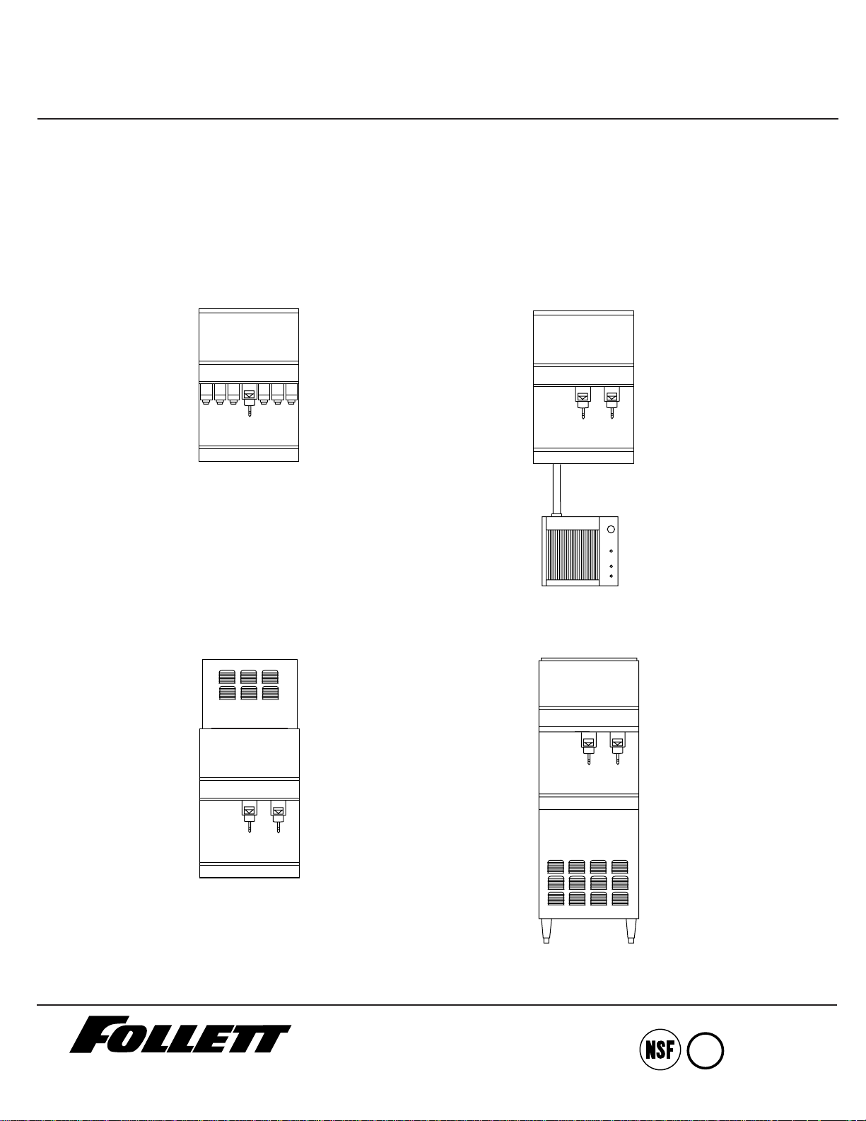
Manual load
Automatic load
with remote icemaker
Automatic load
with top-mounted icemaker
Automatic load
with icemaker in base
Cool Ideas For Ice Management
U
®
L
®
Page 2
Welcome to Follett
Follett ice dispensers enjoy a well-deserved reputation for excellent performance, long-term reliability and outstanding
after-the-sale support. To ensure that this dispenser delivers that same degree of service, we ask that you take a
moment to review this manual before operating the dispenser.
This manual is designed to explain the operation of your dispenser. If you have any questions or need technical help at
any time, please call our technical service group toll free, (800) 523-9361 or (888) 2-FOLLETT, or (610) 252-7301.
Operation
Before you begin
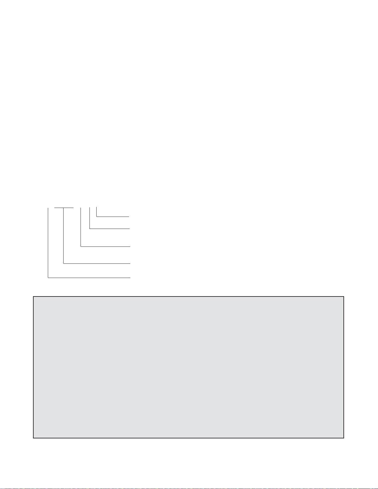
Check your paperwork to determine which model you have. See the explanation of 110 series model numbers below.
Important cautions
• The dispenser bin area contains mechanical, moving parts. Keep hands and arms clear of this area at all
times. If access to this area is required, power to unit must be disconnected first.
• Follett manual load dispensers can accommodate most cube/cubelet ices up to 1" square,
compressed nugget and nugget ices. Crushed, flake, bagged or congealed ice cannot be used.
Use of these ices can jam dispenser and void warranty. Separate any waffle-like sections of cubes
before adding to dispenser. For ice type compatibility questions, contact Follett toll free at
(800) 523-9361 or (888) 2-FOLLETT, or (610) 252-7301.
• Follett recommends a Follett QC4-FL4S water filter system (order #AFSYSTMFL4S) be installed in the
icemaker inlet water line.
• Ice is slippery. Maintain counters and floors around dispenser in a clean and ice-free condition.
• Ice is food. Follow recommended cleaning instructions to maintain cleanliness of delivered ice.
• Countertop dispensers on legs can be inadvertently moved. Care should be taken when operating and cleaning to
avoid accidents.
C110R5A
Condenser type – A = air-cooled, W = water-cooled
Icemaker location – R = remote icemaker; T = top-mounted icemaker .
Note: No letter is used to indicate icemaker located in base of freestanding units.
Approx. capacity in lbs – 110 series = 110 lbs (50kg) manual load, 90 lbs
(41kg) auto load
Dispenser configuration – C = countertop, F = freestanding
Icemaker capacity – 5 = 400 lbs (181kg) day; 10 = 800 lbs (363kg)/day
Page 3

Electrical specifications
Standard electrical – 115V, 60 Hz, 1 phase
110 series manual load – C110 – 2.0 amps, max. fuse size 15 amps
110 series automatic load – requires separate circuit and disconnect for icemaker and dispenser
(exc. F1105A/W)
C110R5A/W, C110T5A/W – Icemaker 11.0 amps, max. fuse size 20 amps
Dispenser 2.0 amps, max. fuse size 15 amps
F1105A/W – 13.0 amps, max. fuse size 20 amps
Alternate electrical configurations (for non-domestic use) – 230V, 50 Hz, 1 phase
110 series manual load – Max. fuse size 15 amps
C110 –.8 amps C110B – 1.2 amps
110 series automatic load – requires separate circuit and disconnect for icemaker and dispenser (exc. F1105A/W)
C110R5A/W, C110T5A/W – Icemaker 6.0 amps, dispenser .8 amps, max. fuse size 15 amps
F1105A/W – 6.8 amps
Model C110 is equipped with cord and plug. All other models to be hard wired. Equipment ground required. Electric
disconnect required within 10 ft (3m) of dispenser.
Plumbing specifications
Countertop 110 series
Dispenser 3/4" FPT dispenser drain
Icemaker 1/2" MPT icemaker drain
3/8" FPT water inlet
3/8" FPT condenser inlet (water-cooled condenser only)
1/2" FPT condenser drain (water-cooled condenser only)
Freestanding 110 series (Models F1105A/W)
Dispenser 3/4" FPT dispenser drain
Icemaker 3/8" FPT water inlet
3/8" FPT icemaker drain
3/8" FPT condenser inlet (water-cooled condenser only)
1/2" FPT condenser drain (water-cooled condenser only)
Note: Water disconnect within 10 feet (3m) of dispenser suggested for automatic load units.
Drain should be hard piped, insulated and maintain min. 1/4" per foot (6mm per 304mm) slope.
How dispenser works
Follett's 110 series ice dispensers are available as either manual load models (using ice from another source) or
automatic load models fed from one or two Follett 400 lbs (181kg)/day icemakers. Depending on the model, the icemaker
may be located in the base of the dispenser, mounted on top or remoted to a location up to 20 feet (6m) from the
dispenser. In all models, ice is stored in the upper section of the dispenser. On lever and pushbutton dispensers, when
the dispenser lever or button is pushed, the ice dispense solenoid is energized. This opens the gate and activates the
dispense motor. This causes the wheel assembly in the storage area to turn, moving ice to the dispense chute where it
drops by gravity into the container.
In automatic load models, ice is made in the icemaker section which may be located in the base, top-mounted or remoted
from up to 20 ft away. As water freezes to the inside walls of the evaporator, a rotating stainless steel auger removes ice
and carries it to the top of the evaporator assembly where it is compressed and extruded through an outlet port. The ice is
then pushed through the tube to the storage compartment in the top of the dispenser. When the storage area is full, a bin
thermostat opens and shuts off the icemaker.
Automatic load units are equipped with a level fill circuit that maximizes fill in the storage area by rotating the wheel at
intervals until the bin is completely filled. When the bin is filled, a bin stat shuts off the icemaker to avoid overfilling of the
bin. The
icemaker will restart after 20 minutes if the bin stat is calling for ice.
2
Page 4
How SensorSAFE™ accessory works
Follett’s SensorSAFE accessory maximizes sanitation and minimizes the possibility of cross-contamination by
eliminating physical contact between the cup or container and the dispenser. Sensors in the panel use reflected infra-red
light to detect the presence of the container and send a signal to a control board which then activates the appropriate
components for ice or water dispensing. The SensorSAFE package includes a cleaning switch under the left side of the
front cover which temporarily shuts off dispensing to allow cleaning of the panel and lenses. If the switch is not turned
back on after cleaning, the dispenser automatically resets to normal operation after two minutes. SensorSAFE also
includes a time limit safety feature which automatically stops ice dispensing after one minute of continuous dispensing.
Dispensing can be resumed by moving the container away from the dispenser and returning it to the activation zone.
How chilled water accessory works
Follett’s chilled water accessory uses ice from the dispenser’s storage hopper to chill the incoming water supplied to the
water station. The water chiller assembly is located in the dispenser cabinet under the storage hopper. As ice is
dispensed, or the wheelmotor is energized during the level fill cycle, ice is automatically fed into the water chiller
assembly to chill the water coil inside the assembly.
To start-up and operate dispenser
1. Follow cleaning instructions provided in installation manual(s) packed with equipment before operating dispenser.
2. Follow appropriate start-up instructions provided in installation manual(s) for manual loading restrictions and/or
automatic load start-up requirements.
Cleaning
This equipment must be cleaned periodically to insure the quality of ice and/or beverage you are providing. Follett
recommends the periodic cleaning schedule listed below. Use only the recommended cleaning solutions. Do not use
solvents or abrasive cleaners. Avoid the use of metal scrapers or sharp objects.
• Always disconnect power before cleaning dispenser(s).
• Do NOT run plastic parts (dispense chute cover, dispense wheel) through a dishwasher.
Solution A: Prepare a cleaning solution (200 ppm of available chlorine content) of Ecolab Mikro-chlor Cleaner or
equivalent chlorinated detergent. Cleaning solution temperature must be at 75˚ – 125˚ F (24˚ - 52˚C).
Solution B: Prepare a sanitizing solution (50 ppm of available chlorine content) of Ecolab Mikro-chlor Cleaner or
equivalent chlorinated detergent. Sanitizing solution temperature must be at 75˚ – 125˚ F (24˚ - 52˚C).
Recommended daily cleaning of drain pan (dispensers with beverage valves only)
1. Remove all debris from drain pan.
2. Slowly pour 1 gallon (4L) hot water into drain pan to keep drain lines clear.
Recommended weekly cleaning (all units)
1. Wash drain pan and grill with Solution A above. Rinse thoroughly.
2. On units with beverage valves, remove nozzles and diffusers from valves, soak for at least 10 minutes in cleaning
Solution A, rinse, sanitize with Solution B and reinstall.
3. Slowly pour solution of one cup (8oz/237ml) household bleach mixed with one gallon (3.8L) hot water into drain pan
to help prevent algae growth in drain lines.
3
Follett manual load dispensers can accommodate most cube/cubelet ices up to 1"
(26mm) square, as well as nugget and compressed nugget ices. Crushed, flake, bagged
or congealed ice cannot be used. Use of these ices can jam dispenser and void
warranty. Separate any “waffle-like” sections of cubes before adding to dispenser.
!
Page 5

SensorSAFE™dispensers – Deactivate dispenser by depressing and releasing clean switch located on left side of
unit under top front cover. Clean lens using soft cloth and mild, non-abrasive
cleaner. Reactivate dispenser by
depressing and releasing clean switch a second time.
Recommended quarterly cleaning of dispenser hopper
1. Remove top front cover.
2. Turn power switch to “OFF” position.
3. Remove ice from storage area and wash drain pan grill with Solution A above. Rinse thoroughly.
4. Remove center thumbnut on dispense wheel in bottom of storage area, tilt rear of wheel up and lift to remove.
5. Wipe lid, dispense wheel, inside of storage area and ice chute (units with ice-waterbath beverage cooling only) with
damp sponge wrung out in Solution A.
6. Rinse above components thoroughly with clear water, and sanitize with Solution B; do not rinse.
7. On units with beverage valves, remove nozzles and diffusers from valves, soak for at least 10 minutes in cleaning
Solution A, rinse, sanitize with Solution B and reinstall.
8. Slowly pour solution of one cup (8oz/237ml) household bleach mixed with one gallon (3.8L) hot water into drain pan
to help prevent algae growth in drain lines.
9. Reinstall dispense wheel and secure.
10. If unit is equipped with chilled water accessory, also see below.
If dispenser is equipped with chilled water accessory
1. Remove two (2) screws securing splash panel and lay splash panel on dispenser drain pan.
2. Disconnect 3/4" drain line from bottom of chilled water canister.
3. Loosen (do not remove) screw securing right bracket of chilled water canister to bottom of dispenser hopper.
4. Rotate canister forward to release right bracket, then slide canister to right to disengage left bracket.
5. Remove chilled water coil from canister and clean with cloth wrung out in Solution A.
6. Wipe inside of chilled water canister with cloth wrung out in Solution A.
7. Rinse all above items with damp cloth wrung out in clear water.
8. Sanitize all above items with damp cloth wrung out in Solution B. Do not rinse.
9. Reinstall chilled water coil into canister (rubber alignment grommet on coil tubing must be located outside chilled
water canister to hold coil securely against canister wall).
10. Reinstall chilled water assembly on dispenser and tighten screw securing right bracket.
11. Reconnect 3/4" drain line to chilled water canister.
12. Reinstall splash panel and top front cover.
13. Put unit back in service (see below).
Putting unit back in service after cleaning
1. For manual load units, fill unit with an approved ice (see caution statement page 1).
2. For automatic load units, turn bin signal switch(es) and dispenser power switch(es) to “ON” position and allow storage
area to fill.
3. Push lever to test that unit is functioning properly.
Cleaning soda lines
(models with valves only)
For frequency and instructions on cleaning bag-in-box or 5 gallon (19L) tank soda systems and lines, consult your syrup
supplier.
Brixing soda valves
(models with valves only)
In order to maintain a quality drink, the soda valves must be adjusted (“brixed”) on a routine basis. This is done by
adjusting the flow of carbonated water (called “soda”) and syrup to an established ratio. A special “brixing cup” is required
to determine what adjustments should be made. Different types of valves and flavors require different techniques and
ratios. Consult with your syrup supplier for specific instructions for the valves and flavors your facility is using.
4
Quarterly cleaning of icemaker system
Units with icemakers require icemaker cleaning at least every 3 months, and more often if local water conditions
dictate. Failure to clean icemaker will result in decreased performance and potential damage to icemaker. Refer to
Icemaker Operation and Service Manual for specific cleaning instructions.
Page 6
Service
Before calling for service
1. Check to make sure that there is ice in dispenser storage area.
2. Check to make sure that congealed cubes are not causing a jam.
3. Check that power cord is plugged in (manual load models only).
Troubleshooting
Symptom
1. Does not dispense ice
2. Does not dispense
water
3. Water runs
continuously
4. Does not dispense
beverage
5. Dispense wheel rotates
continuously
6. Icemaker runs
continuously
Possible cause
a. Power switch “off” or faulty.
b. Faulty dispense switch.
c. Wheel motor malfunction.
d. Non-compatible ice used in
dispenser.
e. Faulty dispense solenoid.
a. Dispense switch faulty.
b. Faulty water solenoid.
c. Solenoid plugged by debris.
a. Dispense switch contacts burned
shut.
b. Debris preventing valve from closing.
a. Key switch (accessory) in “off”
position or faulty.
b. Transformer not supplying 24V to
valves.
a. Dispense switch contacts burned
shut.
b. Faulty timer supplying power to pin
#1 at all times.
c. Welded contacts on level fill relay.
a. Faulty or incorrectly positioned bin
stat.
b. Incorrect field wiring.
Solution
a. Check switch. Turn on or replace if
faulty.
b. Replace switch.
c. Check motor and capacitor and
replace as required.
d. Load compatible ice. (Call Follett for
guidance.)
e. Check solenoid and replace if faulty.
a. Check switch and replace if faulty.
b. Check solenoid and replace if faulty.
c. Remove and clean valve.
a. Check switch and replace if faulty.
b. Remove and clean valve.
a. Turn key switch on or replace.
b. Check for correct voltage to primary
side. If correct, replace transformer.
a. Replace dispense switch.
b. Replace timer.
c. Replace relay.
a. Check for proper positioning. If stat
does not open when ice is placed on
capillary tube, replace stat.
b. Check that icemaker receives its bin
signal from dispenser.
5
Disconnect power to unit before putting hands or arms in storage area or before
attempting any repair or service to equipment.
!
4. Check that circuit breaker is on.
5. Check that all drains are clear.
Page 7

Troubleshooting SensorSAFE™board and sensors
ACTION
Check LEDs on control
board
Place cup under drop
zone
LED STATUS
PWR CLN ICE/WTR
OFF OFF OFF
ON ON OFF
ON OFF OFF
ON OFF ON
SOLUTION
Check circuit breakers and power switch;
restore power or replace defective switch.
Depress clean switch located under left side of
front cover to return board to normal operation
Troubleshoot appropriate lens/sensor and
replace if required. (see Lens/Sensor
Troubleshooting below)
Verify power on appropriate output terminal
(WTR, SOL or WM) on control board and
replace board if required; if board tests okay,
troubleshoot appropriate dispenser component
(page 5).
Problem: Does not dispense ice and/or water
ACTION
Check LEDs on control
board
LED STATUS
PWR CLN ICE/WTR
ON OFF ON
ON OFF OFF
SOLUTION
Troubleshoot appropriate lens/sensor and
replace if required. (See Lens/Sensor
Troubleshooting)
If there is power on any output terminal (WTR,
SOL or WM) on control board, replace board.
Problem: Dispenses ice and/or water continuously
Board guide
LEDs, when illuminated, indicate the following: PWR (Board power), CLN (Cleaning, no dispensing cycle), ICE (Ice
dispensing activated), WTR (water dispensing activated).
Terminals: LI (incoming power, hot), L2 (neutral terminals), WTR (power terminal for water solenoid), SOL (power
terminal for dispense gate solenoid), WM (power terminal for wheelmotor), CLN (terminals for clean cycle switch).
Lens/sensor troubleshooting
Turn dispenser power switch off. Remove splash panel. Disconnect wires from output (WTR, SOL, WM) terminal(s)
on board. Gently remove appropriate sensor/mounting block assembly from panel by moving block sideways until
edge of block clears retaining tab of panel. Inspect lens and sensor assembly for foreign material, and clean using a
mild, non-abrasive cleaner. Turn dispenser power on and test sensor by moving hands through activation area (no
closer than 3/16") in front of sensor. If LED on board turns on and off, sensor is working properly and dispenser may
be reassembled. If LED does not come on, switch sensor lead on board to working sensor lead and retest. If the
opposite LED comes on, board is defective and must be replaced. If LED does not come on, sensor is defective and
must be replaced.
6
Page 8

Parts removal
Dispense chute removal
1. Remove stainless front cover.
2. Turn power to unit off (ON/OFF switch is located at right side of electrical box).
3. Slide plastic dispense chute cover up and out to remove.
4. Remove four (4) fasteners holding dispense chute and bracket assembly in place and remove chute.
Dispense wheel removal
1. Remove all ice from storage area of dispenser.
2. Remove baffle.
3. Remove center thumbnut and threaded rod from dispense wheel.
4. Tilt rear of wheel up and lift off motor drive shaft.
Drive bar removal
1. Remove dispense wheel from dispenser (See above).
2. Remove two (2) thumbscrews from agitator bar mounted on wheel.
3. Pull drive bar out of channel in bottom of wheel.
Wheel motor removal
1. Remove dispense wheel from inside storage area of bin (see above).
2 Unplug wires running from motor to capacitor.
3. Remove four (4) bolts holding motor to motor bracket.
7
Do not remove motor bracket. Bracket location is critical to alignment of dispense
wheel and is not field adjustable.
!
Page 9

Wiring diagrams
How unit works — lever actuated model
The wheel motor and dispense solenoid are energized through the power and ice dispense switches. The water
solenoid is energized through the power and water dispense switches.
Automatic load units with either top-mounted or remote icemakers are equipped with a level fill circuit to maximize
fill in the ice storage area by rotating the wheel at intervals until the bin is completely filled. In these units the
icemaker is powered through the N.C. bin thermostat. While the bin level thermostat is calling for ice, the level fill
timer is energized. Every 18 minutes the timer energizes the level fill relay, rotating the wheel motor for 5
seconds. When ice builds up around the bin thermostat, the contacts open, cutting the bin signal to the icemaker.
8
Lever actuated dispensers
FROM
JUNCTION
BOX
BLACK
POWER
SWITCH
BLACK
BLACK
BIN
T-STAT
BLACK
BLACK
RED
POWER SUPPLY
BLACK WHITE
DISPENSE SWITCH
PURPLE
1
4
R1
WS
ORANGE
BLACK
7
WATER SOLENOID
DISPENSE
SOLENOID
DS
M
WHEEL MOTOR
WHITE
WHITE
FROM
JUNCTION
BOX
BIN SIGNAL
SWITCH
BLACK
RED
BIN SIGNAL
TO ICEMAKER
PRI
TRANSFORMER
SODA VALVES
V
VVVV
24V
BROWN
LEVEL FILL
TIMER
18 MIN OFF
5 SEC ON
V
1
2
3
BLACK
WHITE
WHITE
R1
LEVEL RELAY
WHITE
Page 10

How unit works — SensorSAFE™models
When a container is placed within the actuation zone below the ice or water chute on the SensorSAFE dispenser
models, an invisible, randomly-generated infra-red signal is emitted, reflected off the container and detected by
the sensor. The sensor then sends a signal to the control board to activate the appropriate components to
dispense ice or water. LED’s on the board indicate when the board is receiving a signal from the sensors.
A safety, shut-off feature automatically shuts off dispensing after one minute of continuous activation. Dispensing
can be restarted by moving the container away and then returning it to the actuation zone.
Dispensing can be temporarily suspended for cleaning by pressing and releasing the clean switch, located under
the left side of the top front cover. Pressing and releasing the button a second time will return the dispenser to
normal operation. If the button is not pressed a second time, the dispenser automatically resumes normal
operation (CLN LED goes out) after two minutes. An LED on the control board will light to indicate that dispensing
has been suspended by activation of the clean switch.
9
SensorSAFE dispensers
120 VAC
POWER
SWITCH
BIN LEVEL
THERMOSTAT
BLACK BLACKBLACK
BIN LEVEL
SWITCH
RED
BROWN
BLACK
WTR
BLACK
S
WATER
SOLENOID
WHITE
WHITE
WHITE
WHITE
WHITE
WHITE
L1
L2
PWR
CLN
SOL
ORANGE
S
GRN
ICE
WTR
WM
CLEAN
SWITCH
ICE
GATE
SOLENOID
WHEELMOTOR
CLN
PURPLE
ICE
SENSOR
WTR
SENSOR
1
R1
BIN SIGNAL
TO
ICEMAKER
BLACK
4
7
BLK
M
RED
1
2
R1
BLACK
3
WHITE
WHITE
Page 11

Thermostat locations – freestanding units and units with remote icemakers
10
Detail A–A
hand bend cap
tube end to
approx. 45˚ as
shown in Detail
A–A.
bin thermostat
Thermostat locations – units with top-mounted icemakers
Top view
bin thermostat
Top view
A-------A
NC
Approx.
3/4"
NC
45˚
bend
Page 12

Replacement of ice transport tube – Units with top-mounted icemakers
1. Slip a hose clamp on end of transport tube without pins, immerse this end
in cup of hot water to soften hose, then push it on evaporator port of
icemaker.
2. Fasten tube on evaporator port with hose clamp, being sure that clamp is
positioned on evaporator side of flange. Tighten clamp.
3. Insert loose end of ice tube into bracket on icemaker base as shown in
drawing.
4. Pull up on ice tube to seat pins in bracket.
Ice transport tube replacement – Freestanding units and units with remote icemakers
1. Remove top and rear access panel from dispenser (and lower front panel on freestanding unit).
2. Disconnect existing ice tube from engaging pin and pull down through dispenser chase.
3. Disconnect opposite end of tube from icemaker.
4. Run end of new ice transport tube with 3/16" (5mm) hole
through right hand knockout in back of dispenser or through
counter into bottom of dispenser, being careful to avoid any
bends with less than a 6" (153mm) radius.
5. Insert tube in internal chase in rear inside corner of dispenser
(right side as you face rear of dispenser) and push up into
storage area.
6. Push 3/16" (5mm) hole near end of tube into pin on ice tube
bracket (see drawing at right).
Steps 6 – 7 for units with remote icemakers only
7. Install supplied insulation to run of transport tube required for
your site, leaving approximately 2" (51mm) of tube exposed at free end.
8 Check that insulated tube runs continuously uphill to dispenser with no dips.
All units
9 Place free end of tube in a cup of hot water to soften, slip supplied hose clamp onto
tube and push tube onto exit port of evaporator. DO NOT TWIST HOSE WHEN
SECURING TO EVAPORATOR.
10. Fasten tube on port with hose clamp, being sure that clamp is positioned on evaporator
side of flange.
11. Tighten clamp.
11
Correct installation of ice transport tube is critical to icemaker performance.
Replacement ice transport tubes must be insulated and must run continuously
from icemaker to dispenser with no dips in line and no bends with a radius of less
than 6” (153mm).
!
If preparing tubing not supplied by Follett, dispenser end of
tube must be fitted with mounting pins as shown in
drawing.
!
ice tube
mounting pin
plate
gasket
cap tube
bracket
ice
deflector
capillary
tube
ice tube
bracket
1"
(26mm)
3/16"
(5mm)
hole in
ice tube
engaging pin
ice
tube
ice tube
bracket
icemaker
base
Back wall
A
3/16" (5mm)
dia. hole
Section A–A
1"
(26mm)
A
Page 13

Part # Description Reference #
501445 Top, dispenser 1
501819 Lid, top Not shown
501502 Cover, front, stainless steel, with “cold drink” graphics 2
501596 Cover, front, stainless steel, with “ice” graphics 3
500089 Leg kit, 6" (153mm) for F1105A/W units only 4
501478 Leg kit, 4" (102mm), adjustable (set of 4) – N/A for top-mounted models Not shown
501794 Cover, front, for bottom of F1105A/W 5
502067 Drain pan base assembly (includes 501915 and 501837) 6
501456 Plug, ice-waterbath Not shown
501915 Drain pan, plastic 7
501837 Grill, drain pan 8
501286 Key, beverage lock Not shown
501651 Keylock assembly Not shown
502083 Rear panel, base stand, perforated Not shown
502222 Valve, water shutoff Not shown
502433 T fitting Not shown
502225 Assembly, water inlet, freestanding units Not shown
502268 Fitting, drain and mounting plate Not shown
502154 Top, dispenser (C110T5A/W) Not shown
500376 Strainer, water Not shown
1
2
3
5
7
8
4
12
6
Parts
cold drinks
Page 14

Part # Description Reference #
502057 Fastener, dispense chute bracket (4 req. per bracket) 1
502356 Tube, water station 2
502262 Fitting, 1/8" MPT x 3/8" comp 3
502246 Fitting, 1/8" MPT x 1/4" comp 4
502243 Solenoid valve, water, 120V, 60Hz 5
502576 Solenoid valve, water, 230V, 50Hz 5
501829 Switch, dispense, lever actuated ice dispensing (includes 501841) 6
502247 Bracket, chute (includes fasteners 502057) 7
501841 Boot, dispense switch lever (mounts on 501829 switch) Not shown
502359 Switch, dispense, lever, water 8
502358 Lever 9
502355 Retainer, bracket, water solenoid 10
502507 Cover, dispenser chute, plastic, lever operation (includes labels) 11
502357 Solenoid assy, water, 120V, 60Hz (includes 502243, 502245, 502246, 502256 and 502262) 12
502577 Solenoid assy, water, 230V, 50Hz (includes 502243, 502245, 502246, 502256 and 502262) 12
502248 Chute, ice 13
502249 Chute, water 14
13
1
2
3
5
4
8
11
13
14
9
8
12
6
10
9
7
Dispense chute and splash panel areas – lever models
Dispense chute and splash panel areas – SensorSAFE™models
Page 15

Part # Description Reference #
502250 Cover, dispense chute 1
502248 Chute, ice 2
502249 Chute, water 3
502057 Fastener, dispense chute bracket 4
502690 Sensor, lens Not shown
502254 Splash panel (includes(2) 502690) 5
502357 Solenoid assy, water, 120V, 60Hz (includes 502243, 502356, 502355, 502256 & 502262) 6
502577 Solenoid assy, water, 230V, 50Hz (includes 502243, 502356, 502355, 502256 & 502262) 6
502241 Assembly, sensor and mounting block (includes 502239 and 502240) 7
502239 Block, sensor mounting 8
502240 Sensor 9
502355 Bracket, water solenoid 10
502356 Tube, water station 11
502243 Solenoid valve, water, 120V, 60Hz 12
502576 Solenoid valve, water, 230V, 50Hz 12
502246 Fitting, 1/8" MPT x 1/4" comp 13
502262 Fitting, 1/8" MPT x 3/8" comp 14
502247 Bracket, chute (includes fasteners 502057) 15
502261 Cover, front, SensorSAFE models Not shown
502255 Bracket, clean switch, SensorSAFE Not shown
501139 Clean switch, SensorSAFE Not shown
14
1
2
3
5
11
7
4
14
13
12
10
9
6
8
3
15
Page 16

Part # Description Reference #
500514 Thermostat, bin level 1
501369 Relay, level fill 2
501601 Timer, level fill 3
500006 Switch (front), dispenser power 4
500006 Switch (rear), icemaker bin signal 4
502242 Control board, SensorSAFE 5
502255 Bracket, clean switch, SensorSAFE Not shown
501139 Clean switch, SensorSAFE Not shown
WM
WTR
SOL
CLN
NEUTRAL
L1
GND
WTR
ICE
1
2
3
5
4
Electrical box (front view)
SensorSAFE™models
15
Part # Description Reference #
500514 Thermostat 1
501369 Relay, level fill (auto load units only) 2
501375 Relay, level fill, non-domestic units, 230V, 50Hz (auto load units only) 2
501601 Timer, level fill (auto load units only) 3
501700 Timer, level fill, non-domestic units, 230V, 50Hz (auto load units only) 3
501604 Terminal block 4
501321 Transformer (units with beverage valves) 5
501429 Transformer, non-domestic units, 230V, 50Hz (units with valves) 5
500006 Switch (front), dispenser power 6
500006 Switch (rear), icemaker bin signal 6
1
2
3 4
5
6
Electrical box (front view)
lever models
L1
NEUTRAL
SOL
WTR
GND
CLN
WM
ICE
WTR
Page 17

16
Part # Description Reference #
501493 Wheel, dispense (includes 501320, 501494, 501441) 1
501346 Agitator, fixed 2
501603 Thumbnut, fixed agitator rod 3
501802 Baffle, ice 4
501340 Capacitor, run, dispense motor 5
501803 Motor, wheel (includes 501340) 6
501804 Motor, wheel, non-domestic units, 230V, 50 Hz 6
502235 Bracket, wheel motor 7
501838 Drain tube assembly 8
501494 Agitator, rotating 9
500905 Nut, knurled, dispense wheel 10
501612 Stud and nut assembly, dispense wheel 11
501441 Drive bar assembly (includes 501612) 12
501806 Drain pan, rear 13
502236 Drain assembly, hopper (includes plastic tube) Not shown
502101 Manifold, carbonated water Not shown
Side view cutaway
Dispense wheel - top view
Dispense wheel - bottom view
2
4
1
5
6
8
9
10
12
3
11
7
13
Hopper components
Page 18

Part # Description Reference #
502056 Bracket, ice tube 1
501842 Bracket, ice tube (units with top-mounted icemakers) 2
501616 Ice deflector/cap tube bracket (units with top-mounted icemakers) 3
501613 Thumbnut, cap tube bracket 4
501795 Ice transport tube assembly (units with top-mounted icemakers) - sold as 1.6 ft section 5
501613 Screws, knurled 6
501176 Ice transport tube insulation (remote units only) – sold by ft Not shown
502326 Ice transport tube assembly (freestanding, air-cooled) Not shown
502327 Ice transport tube assembly (freestanding, water-cooled) Not shown
502522 Ice transport tube - 10 ft (3m), for dispensers w/remote icemakers Not shown
502523 Ice transport tube - 20 ft (6.1m), for dispensers w/remote icemakers Not shown
502824 Gasket, ice entry 7
Top view - units with
top-mounted icemakers
4
3
5
2
2
Side view - units with
top-mounted icemakers
17
Top view – freestanding units and units
with remote icemakers
1
1
6
Side view - freestanding units and
units with remote icemakers
7
NC
NC
Back wall
Page 19

Solenoid dispense assembly
Part # Description Reference #
501830 Solenoid, dispense 1
501844 Solenoid, dispense 230V, 50Hz 1
502040 Cotter pin 2
502039 Linkage, solenoid (includes 502054 grommet) 3
502042 Block, dispense gate 4
502054 Grommet 5
502045 Splash pan, gate assembly 6
502038 Shoulder screw and washer 7
501824 Spring, gate assembly 8
502043 Gate assembly, 115v (includes reference numbers 1 through 8 above)
1
3
4
5
6
8
7
Part # Description Reference #
502598 Coil, chilled water (includes (2) 502599) 1
502599 Fitting, water coil 2
502600 Brackets, chilled water canister, pair (includes screws) 3
502601 Canister, chilled water (includes 502600 and 502605) 4
502605 Elbow, drain 5
502604 Tee, drain Not shown
502603 Assembly, chilled water (includes reference numbers 1 through 5 above)
3
4
1
2
5
18
2
Page 20

207934R00
12/01
Cool Ideas For Ice Management
801 Church Lane • PO Box D, Easton, PA 18044
Toll free (800) 523-9361 • (888) 2-FOLLETT
(610) 252-7301 • Fax (610) 250-0696 • www.follettice.com
U
L
®
®
 Loading...