

Page 1
12 Series - 220 V 60 Hz/230 V 50 Hz
Ice and Water Dispensers
Order parts online
www.follettice.com
Installation, Operation
and Service Manual
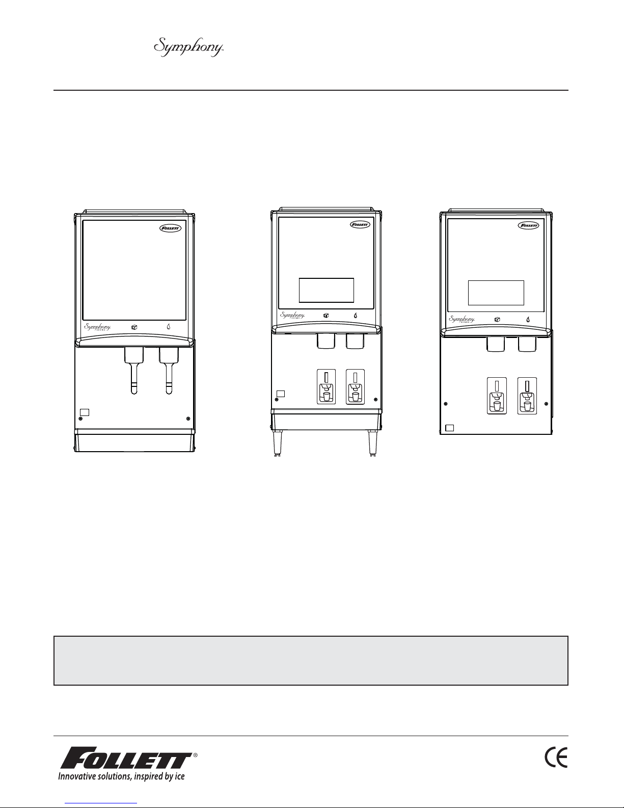
12CI400A-L
countertop dispenser
countertop dispenser with
SensorSAFE infrared dispensing
(shown with legs accessory)
12CI400A-S
12HI400A-S
wall mount dispenser
(available with or
without drain pan)
Following installation, please forward this manual to the appropriate
operations person.
801 Church Lane • Easton, PA 18040, USA
Toll free (877) 612-5086 • +1 (610) 252-7301
www.follettice.com
00124438R05
Page 2

Table of contents
Welcome to Follett Corporation ............................................................................................................................ 3
Important cautions ................................................................................................................................................. 3
Speci cations ........................................................................................................................................................ 4
Installation .............................................................................................................................................................. 5
Installing countertop dispensers without legs .................................................................................................. 5
Installing countertop dispenser with legs accessory ....................................................................................... 6
Installing wall mount dispensers ...................................................................................................................... 7
User information ................................................................................................................................................... 10
Cleaning and sanitizing procedures .............................................................................................................. 10
Dispenser cleaning ........................................................................................................................................ 10
Ice machine cleaning and sanitizing ..............................................................................................................11
Start-up following cleaning ............................................................................................................................ 12
Service information .............................................................................................................................................. 14
Wiring diagram – lever model ........................................................................................................................ 15
Wiring diagram – SensorSAFE model ........................................................................................................... 16
Ice machine operational and diagnostic sequences ..................................................................................... 17
Refrigeration cycle diagram ........................................................................................................................... 22
Ice machine capacity chart ........................................................................................................................... 23
Ice machine data ........................................................................................................................................... 23
Refrigeration system data and requirements ................................................................................................. 24
Dispenser troubleshooting – lever models .................................................................................................... 25
Dispenser troubleshooting – SensorSAFE models ....................................................................................... 26
Ice machine troubleshooting ......................................................................................................................... 27
Disassembly and replacement instructions ................................................................................................... 29
Replacement parts ...............................................................................................................................................33
2 12CI400A • 12HI400A 220 V 60 Hz/230 V 50 Hz Dispensers
Page 3
Welcome to Follett
Follett equipment enjoys a well-deserved reputation for excellent performance, long-term reliability and
outstanding after-the-sale support. To ensure that this equipment delivers that same degree of service, we
ask that you review the installation portion of this manual before beginning to install the unit. Our installation
instructions are designed to help you achieve a trouble-free installation. Should you have any questions or
require technical help at any time, please call our technical service group at (610) 252-7301.
Note: To expedite assistance, all correspondence or communication MUST include the model number, serial
number and complete and detailed explanation of the problem
Before you begin
After uncrating and removing all packing material, inspect the equipment for concealed shipping damage. If
damage is found, notify your shipper immediately and contact Follett Corporation for help in ling a claim, if
necessary.
Check your paperwork to determine which model dispenser you have. Follett model numbers are designed to
provide information about the type and capacity of Follett ice dispensing equipment. Following is an explanation
of model numbers.
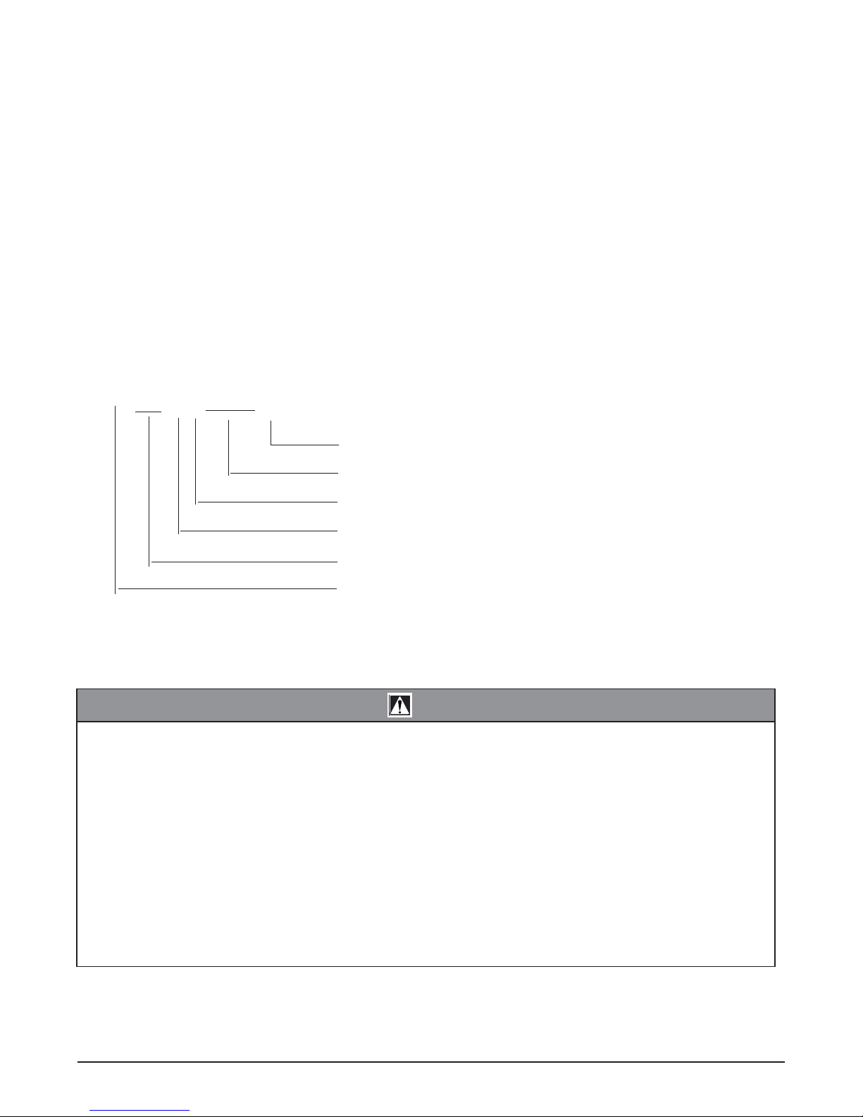
E12CI400A
Condenser type, A = air-cooled
Ice machine capacity in lbs per day
Ice machine location, I = integral
Dispenser con guration, C = countertop, H = wall mount
Approximate storage capacity in lbs
Alternate voltage – C = 220 V 60 Hz
– E = 230 V 50 Hz
CAUTION!
§ Do NOT tilt any unit farther than 30° off vertical plane during uncrating or installation.
§ Dispenser bin area contains mechanical, moving parts. Keep hands and arms clear of this area at all
times. If access to this area is required, power to unit must be disconnected first.
§ Follett recommends installation of an activated carbon filter in ice machine inlet water line.
§ Ice is slippery. Maintain counters and floors around dispenser in a clean and ice-free condition.
§ Ice is food. Follow recommended cleaning instructions to maintain cleanliness of delivered ice.
§ Do not block right side air intake or top air exhaust.
§ Keep ventilation openings in the appliance enclosure or in the built-in structure clear of obstruction.
§ Do NOT use mechanical devices or other means to accelerate the defrosting process.
§ To avoid a hazard due to instability of the appliance it must be fixed according to instructions.
§ The appliance must be positioned so the plug is accessible.
§ If the cord is damaged it must be replaced by special service agent.
12CI400A • 12HI400A 220 V 60 Hz/230 V 50 Hz Dispensers 3
Page 4
Speci cations
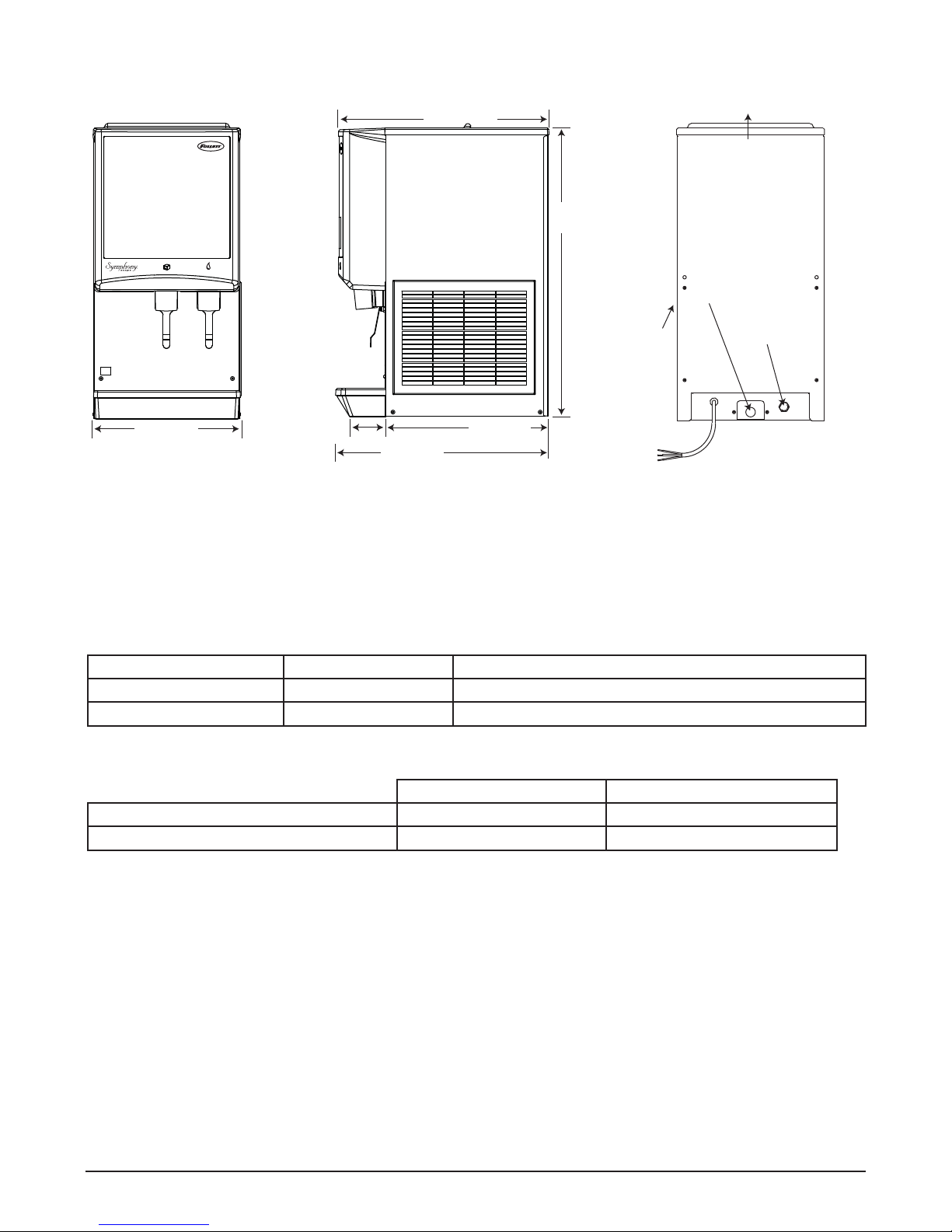
575 mm
(22.625")
826 mm
(32")
air
intake
air exhaust
3/4
" FPT drain
3/8
" FPT
water inlet
407 mm
(16")
Front View Side View Rear View
102 mm (4"
)
597 mm
(23.5")
458 mm
(18")
power cord
Electrical
220 V 60 Hz, 1 phase, 6.5A
230 V 50 Hz, 1 phase, 6.5A
Furnished with 1.8m (6 ft) power cord.
Ambient
Air temp 38 C/100 F Max. 10 C/50 F Min. (Best performance below 27 C/80 F)
Water temp 32 C/90 F Max. 4 C/40 F Min. (Best performance below 21 C/70 F)
Water pressure 5Bar Max./70 P.S.I. 0.7 Bar/10 P.S.I. Min.
Plumbing
C/E12CI400A C/E12HI400A
Dispenser drain 3/4" FPT 3/4" FPT
Water inlet 3/8" FPT 3/8" FPT
Note: Water shut-off recommended within 3m (10 ft) of dispenser. Drain to be hard-piped and insulated. Maintain
at least 20mm per 1m run (1/4" per foot) of slope.
Ventilation clearances
6" (153mm) on right side of dispenser, 6" (153mm) at top for ventilation and 12" (305mm) at top recommended for
service.
Note: Do not block right side air intake or top air exhaust.
Dry weight
79.4kg (175 lbs)
4 12CI400A • 12HI400A 220 V 60 Hz/230 V 50 Hz Dispensers
Page 5
Installation procedures
Before you begin
• All dispensers must be installed level in both directions to ensure proper operation.
• Service and ventilation clearances: 153mm (6") on right side of dispenser, 153mm (6") at top for ventilation
and 305mm (12") at top recommended for service.
• Countertop units installed without legs provide the option of taking utilities out bottom or back of dispenser
(on wall mount units and countertop units with legs, utilities exit from back). See counter cut out drawings for
bottom exiting utilities on units with and without drain pans. For installations where utilities exit through back
of dispenser, refer to back view drawings.
• Wall mount models without drain pan are designed for use above sinks.
• Counter depth must allow front of sink to be a minimum of 597mm (23.5") from wall.
Installing countertop dispensers without legs
1. Position dispenser in desired location,
mark dispenser outline on counter and
remove dispenser.
2. Regardless of whether utilities will exit
through back or bottom of dispenser,
drill four 7/16" holes in counter to
anchor dispenser to counter (Fig. 1).
3. For utilities existing through bottom
only:
(a) Make cut out as shown in Fig.1.
(b) Move plug from drain T to back of
unit (Fig.2).
4. For all units: Apply a thick bead
approximately 6mm (1/4") diameter
of NSF listed silicone sealant (Dow
Corning RTV-732 or equivalent)
6mm (1/4") inside marked outline of
dispenser.
5. Carefully lower dispenser on counter in
proper position and secure to counter
with four (4) 3/8" -16NC bolts.
6. Smooth excess sealant around outside
of dispenser.
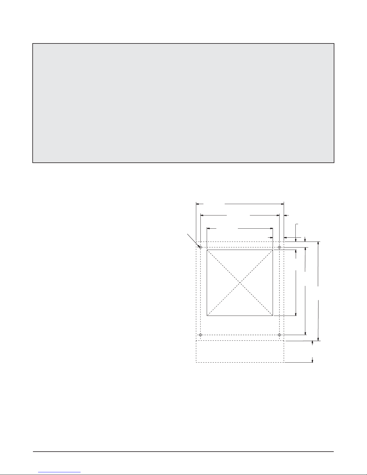
Fig. 1 – Counter information
407mm
(16")
12mm (.437")
diameter
305mm
(12")
connections
366mm
(14.4")
51mm (2")
cutout for
through
bottom
21mm (0.8")
39mm (1.5")
26mm (1")
305mm
(12")
404mm
(15.9")
458mm
(18")
102mm
(4")
12CI400A • 12HI400A 220 V 60 Hz/230 V 50 Hz Dispensers 5
Page 6
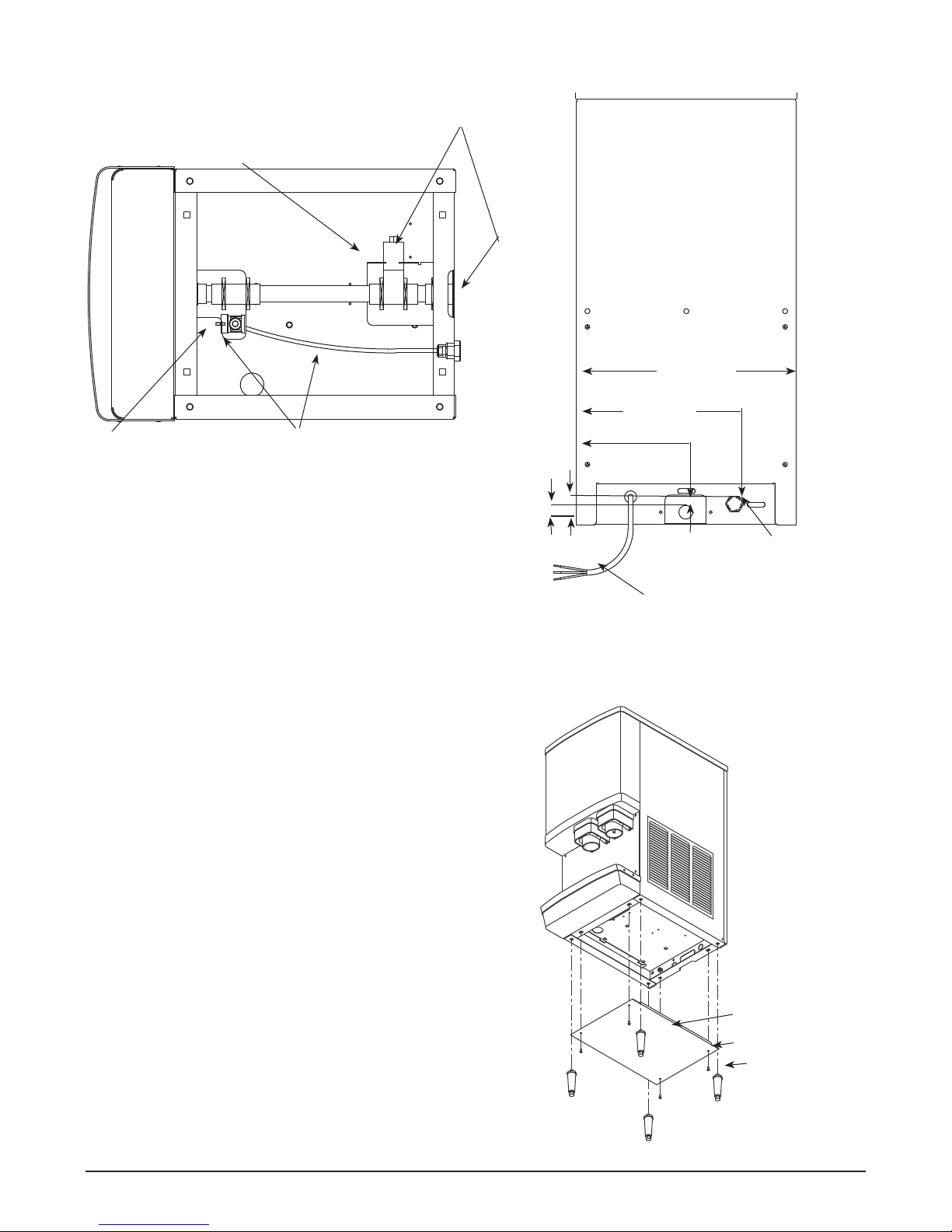
Fig. 2 – Bottom exiting utilities
(countertop units)
moved to back of unit for alternate drain hook up
19mm (3/4") FPT drain
10mm (3/8") push-in
water inlet elbow
Poly tubing and elbow may be
removed for alternate water inlet
hook up by pushing in on the locking
collar while pulling out on the tubing.
Fig. 3 – Rear exiting utilities
(countertop units)
Pipe plug may be
23mm (.9")
39mm
(1.5")
298mm
(11.7" )
206mm
(8.1")
407mm (16")
DRAIN
ICE MACHINE
MAKE-UP WATER
Installing countertop dispensers
with legs accessory
1. Carefully tip dispenser back to expose underside and
block up in place.
Note: Do NOT tilt unit farther than 30° off vertical plane.
2. Screw legs (shipped taped to drain pan of dispenser)
into dispenser bottom, taking care to seat legs securely
against underside of dispenser.
Note: Countertop dispensers that sit on legs (not bolted
to counter) can be inadvertently moved. Care should be
taken when operating and cleaning to avoid accidents.
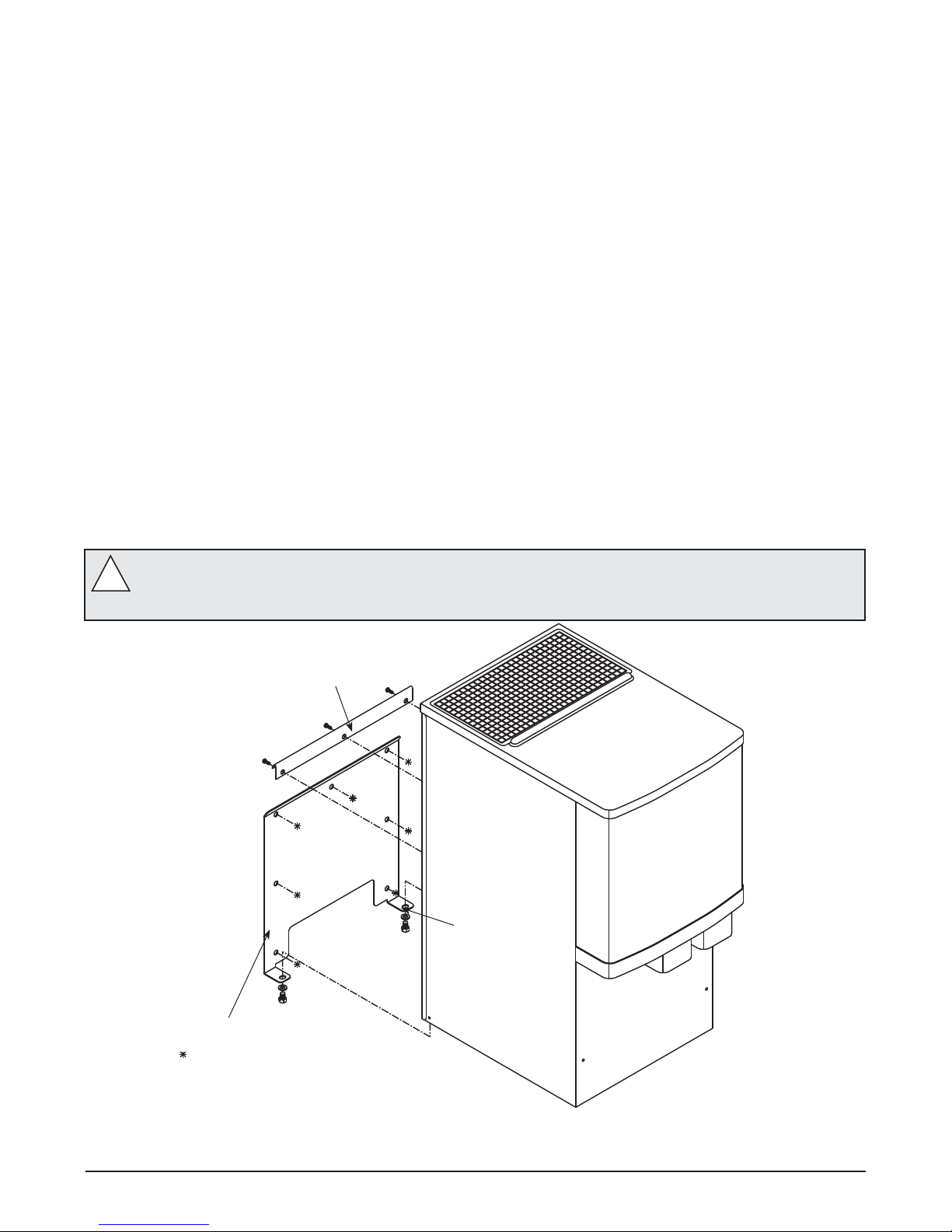
3. Attach bottom panel and hardware to bottom of
dispenser with supplied screws (Fig. 4).
4. Position unit in desired location and adjust bullets on
legs to level in both directions.
5. Make nal connections.
19mm (3/4")
FPT drain
power cord
10mm (3/8") FPT
water inlet
Fig. 4 – Bottom panel assembly
bottom
panel
6 12CI400A • 12HI400A 220 V 60 Hz/230 V 50 Hz Dispensers
screw
leg
Page 7
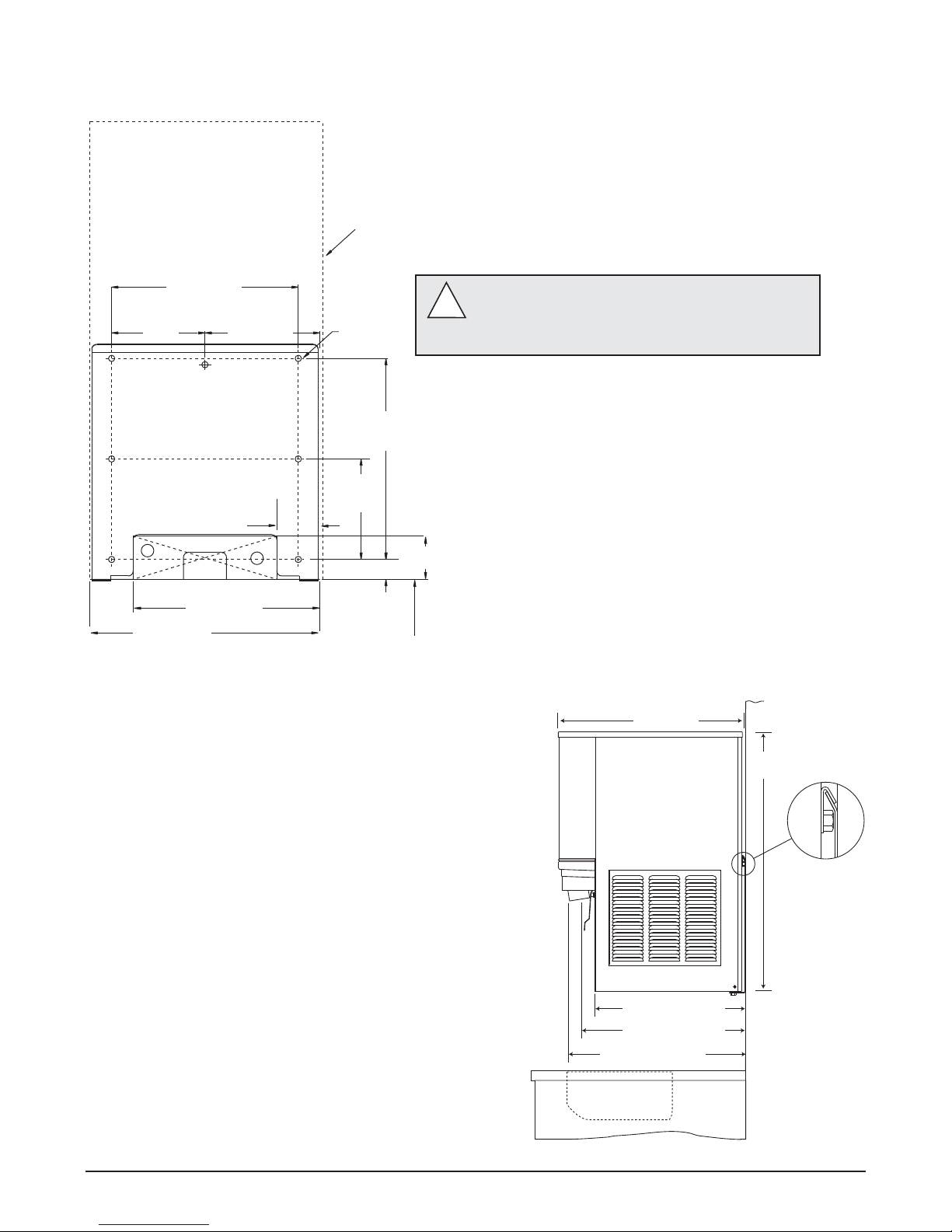
Installing wall mount dispensers
Notes:
No drain pan is provided since the dispenser is intended to be installed above a sink. (Contact Follett if a drain pan is desired.)
SensorSAFE actuation is standard. (Contact Follett if lever actuation is desired. A deeper cabinet will be needed.)
Recommended minimum counter depth and mounting height shown on Fig. 7 ensures that ice will drop into sink.
See Fig. 6 for model dimensions. The dimensions include the 13mm (.5") mounting bracket supplied with the unit.
1. Cut utility hole in wall as shown (Fig. 10).
2. Mount support bracket to wall using fasteners of sufficient strength (fasteners not included, see Fig.6).
3. Rough in water and drain lines (Fig. 10).
4. Lift dispenser onto support bracket, positioning unit so that hook on back of dispenser is captured by support
bracket angle (Fig. 7).
5. Install two (2) supplied 3/8"-16NC screws through bottom of support bracket into bottom of dispenser (Fig.5).
Slotted holes in support bracket allow you to adjust and level the dispenser. Ensure that the top of dispenser
is level or tilted slightly back toward the wall.
6. Make nal connections.
7. Attach bottom panel and hardware to bottom of dispenser (Fig. 8).
Fig. 5 – Wall mount bracket and fastener requirements
WALL PREPARATION: Wall and fasteners must be of sufficient strength to carry weight of unit
(83.9 kg (185 lbs)). Hardware for this is not included.
!
wall mounting bracket
screw
support bracket
12CI400A • 12HI400A 220 V 60 Hz/230 V 50 Hz Dispensers 7
Page 8
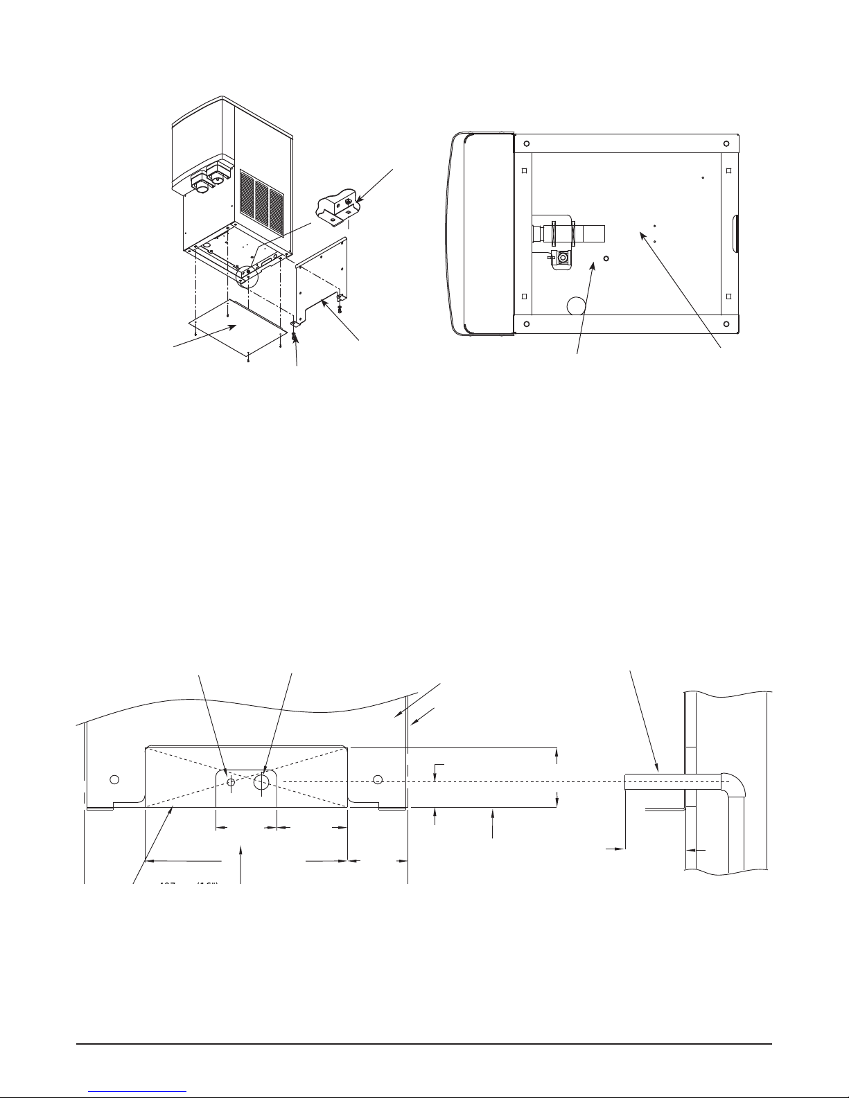
Installing wall mount dispensers
Fig. 6 – Wall mounting dimensions
outline of
dispenser
331 mm (13")
166 mm
(6.5")
77 mm (3")
254 mm (10")
407mm (16")
204 mm (8")
12 mm (.437")
356 mm
(14")
178 mm
(7")
77 mm (3")
36 mm
(1.4")
bottom of dispenser
Caution: Do NOT rest dispenser weight on bottom
of support bracket.
!
Fig. 7 – Wall mount side view
575 mm
(22.625
"
)
826 mm
(32
"
)
470 mm (18.5")
493 mm (19.375")
minimum distance to
sink front
597 mm (23.5")
8 12CI400A • 12HI400A 220 V 60 Hz/230 V 50 Hz Dispensers
Page 9
outline of dispenser
support bracket
bottom of
dispenser
19mm (3/4")
copper drain tube
10mm (3/8")
copper water tube
water and
drain tubing
(3")
77mm
89mm
77mm
(3")
32mm (1.25") MAX
(3") (3.5")
(3")
MIN.
23mm (0.88") MIN
254mm (10")
77mm
77mm
wall
Fig. 8 – Wall mount unit bottom panel assembly Fig. 9 – Wall mount bottom view
nut
bottom panel
support bracket
screw
Fig. 10 – Front view of wall mount bracket – utility location
10mm (3/8") push-in
water inlet
19mm (3/4") FPT
drain
Side view of utilities exiting wall
12CI400A • 12HI400A 220 V 60 Hz/230 V 50 Hz Dispensers 9
Page 10

User information
How the dispenser works
Follett’s 12 series automatic-load ice and water dispensers are equipped with Follett’s 181kg (400 lb)/day ice machine.
In the continuous icemaking process, water freezes to the inside wall of the evaporator. A rotating stainless steel auger
carries the ice to the top of the evaporator where it is compressed and extruded through an outlet port. The ice is
then pushed through a tube to the storage hopper. When the hopper is full, a bin thermostat opens and shuts the ice
machine off. When the dispense mechanism is activated, a dispense motor is turned on, causing the wheel to turn.
This moves ice to the dispense chute where it drops by gravity into the container held below the chute.
How the SensorSAFE accessory works
Follett’s SensorSAFE accessory maximizes sanitation and minimizes the possibility of cross-contamination by
eliminating physical contact between the cup or container and dispenser. Sensors in the panel use re ected infrared
light to detect the presence of the container and send a signal to a control board which then activates the appropriate
components for ice or water dispensing.
The SensorSAFE package includes a cleaning switch under the left side of the front cover which temporarily shuts off
dispensing to allow cleaning of the panel and lenses. If the switch is not turned back on after cleaning, the dispenser
automatically resets after two minutes for normal operation.
SensorSAFE also includes a time limit safety feature which automatically stops ice dispensing after one minute of
continuous dispensing. Dispensing can be resumed by moving the container away from the dispenser and returning it
to the activation zone.
10 12CI400A • 12HI400A 220 V 60 Hz/230 V 50 Hz Dispensers
Page 11
Cleaning/descaling and sanitizing
Periodic cleaning/descaling and sanitizing of Follett’s ice and water dispenser and ice machine system is required
to ensure peak performance and delivery of clean, sanitary ice. The recommended cleaning procedures that follow
should be performed at least as frequently as recommended and more often if environmental conditions dictate.
Cleaning of the condenser can usually be performed by facility personnel. Cleaning/descaling and sanitizing of
the ice machine system should be performed by your facility’s trained maintenance staff or a Follett authorized
service agent. Regardless of who performs the cleaning, it is the operator’s responsibility to see that this cleaning is
performed according to the schedule below. Service problems resulting from lack of preventive maintenance will not
be covered under the Follett warranty.
Recommended cleaning/descaling and sanitizing intervals*
Symphony Frequency
Drain Line weekly
Drain Pan/Drip Pan weekly
Exterior as needed
Condenser monthly (air-cooled only)
Dispenser and Components semi-annually
Ice Machine semi-annually
Transport Tube semi-annually
Ice Storage Area/Bin semi-annually
* Ice machine and dispenser must be cleaned and sanitized prior to start-up.
Weekly
CAUTION!
§ Do not use solvents, abrasive cleaners, metal scrapers or sharp objects to clean any part of the dispenser.
Dispenser drain pan and drain line
1. Pour 1 gal. (3.8 L) of hot tap water into drain pan to ush drains.
Splash panel front, SensorSAFE infrared dispensing
1. Deactivate dispensing by pressing and releasing clean switch located on left side of unit under top front
cover.
2. Clean lens and splash panel front using a soft cloth and mild, non-abrasive, non-chlorine based cleaner.
3. Reactivate dispensing by pressing and releasing clean switch again.
Monthly
CAUTION!
§ Do not use solvents, abrasive cleaners, metal scrapers or sharp objects to clean any part of the dispenser.
Condenser (air-cooled ice machine only)
1. Use a vacuum cleaner or stiff brush to carefully clean condenser coils of lint and debris to ensure optimal
performance.
12CI400A • 12HI400A 220 V 60 Hz/230 V 50 Hz Dispensers 11
Page 12
Semi-Annually (more often if conditions dictate)
§ A cleaning/descaling and sanitizing procedure should always include both the ice machine and dispenser; ice
machine should be cleaned and sanitized rst, followed by the dispenser.
§ Icemaking system can be cleaned/descaled in place.
To ensure that your ice machine and dispenser are cleaned/descaled and sanitized properly, proceed as
follows:
1. Clean/descale the ice machine
2. Sanitize the ice machine
3. Clean/descale the dispenser
4. Sanitize the dispenser
CAUTION!
§ Wear rubber gloves and safety goggles (or face shield) when handling cleaner or sanitizer mixtures.
§ Use only Follett approved cleaners.
§ It is a violation of Federal law to use Solution A or Solution B in a manner inconsistent with their labeling.
§ Do not use solvents, abrasive cleaners, metal scrapers or sharp objects to clean any part of the dispenser.
Solution A: Following manufacturer’s instructions, mix cleaning solution of 1 gal. (3.8 L) 120 F (49 C) water
and 7oz. (198 g) (one 7oz. packet) of Follett SafeCLEAN™ ice machine cleaner/descaler
(P/N00132001).
Solution B: Following manufacturer’s instructions, mix a sanitizing solution of 1 gal. (3.8 L) 120 F (49 C) water
and 1.6oz. (48 ml) Nu-Calgon IMS-II Sanitizer (P/N 00979674).
Clean/descale ice machine
1. If ice machine was running recently, ensure that the evaporator is completely free of ice before proceed-
ing.
2. Disconnect power to ice machine.
3. Remove any ice machine panels required to gain access to water reservoir and electrical control box.
4. Turn compressor switch on electrical box of ice machine to OFF position.
5. Remove water reservoir cover and close water supply valve (or block up reservoir oat).
6. Drain water from reservoir by releasing evaporator drain tube from oat reservoir bracket, removing
plug from drain tube and releasing (unclamping) pinch clamp (if equipped).
7. Plug drain hose, replace drain line in reservoir bracket and pour part of Solution A into reservoir, lling
it almost to over owing.
8. Remove stainless steel ice compression nozzle and drain lines and submerge in a cup of SolutionA
while cleaning/descaling rest of system. (Flake ice machines have no ice compression nozzle and drain
lines.)
CAUTION: To avoid potential pitting, do not soak parts in Solution A for more than 45 minutes.
9. Restore power to ice machine (gearmotor will run; compressor and fan will not).
10. Inspect evaporator drain pan and drain line and remove any accumulated scale build up.
11. After 15 minutes, turn power OFF; drain solution from reservoir and evaporator.
12. Fill reservoir almost to over owing with clean water to rinse. Drain. Repeat two more times.
13. Rinse ice compression nozzle and drain lines in clean water.
Sanitize ice machine
14. Submerge ice compression nozzle and drain lines in a cup of Solution B while following steps 15-21.
15. Connect ice transport tube directly onto evaporator outlet port without ice compression nozzle.
16. Fill reservoir almost to over owing with Solution B.
17. Restore power to ice machine (gearmotor will run; compressor and fan will not).
18. After 10 minutes, turn compressor switch to ON position.
19. As unit starts to make ice, continue to pour Solution B into reservoir, maintaining level just below res-
12 12CI400A • 12HI400A 220 V 60 Hz/230 V 50 Hz Dispensers
Page 13

ervoir over ow.
20. Continue to make ice with Solution B for 20 minutes.
21. Turn power to ice machine OFF.
22. Disconnect ice transport tube from evaporator outlet port. Rinse ice compression nozzle and drain
lines in clean water and reinstall on evaporator outlet. Reconnect ice transport tube to ice compression
nozzle.
23. Drain any remaining Solution B from evaporator.
24. Fill reservoir almost to over owing with 120 F (49 C) clean water to rinse. Drain. Repeat two more
times. Re-clamp pinch clamp, replace drain plug, and re-secure drain tube ensuring that end of drain
tube is above water level in reservoir.
25. Open water supply valve (or unblock oat) and replace reservoir cover; restore power to ice machine
and ensure compressor switch is in ON position. Make ice for at least 15 minutes to ush any remaining
Solution B from system (RIDE® ice machines with long ice transport hoses may take longer to ush
out). Discard this ice and all ice made during sanitizing.
Clean/descale dispenser
26. Remove and discard all ice from storage hopper.
27. Ensure power is disconnected. Remove ice storage hopper cover.
28. Remove center thumbscrew, locking plate, two wingnuts and backing plate from front of storage hopper
(see Page 29).
29. Remove threaded rod, agitator, baffle, and wheel in this sequence (see Page 29).
30. Remove and disassemble (if applicable) dispense chutes.
31. Thoroughly wipe hopper lid, dispense wheel, baffle, inside of storage area and dispense chutes with
cloth soaked in SolutionA.
Note: To avoid possible damage to dispense motor assembly, use only a damp cloth to clean storage hopper.
Do not allow water to run through the center hole in the bottom of hopper.
32. Remove grille and wash with Solution A. Rinse thoroughly with clean water.
33. Rinse all above items with damp cloth wrung out in clear water.
Sanitize dispenser
34. Wipe all above items with damp cloth wrung out in Solution B to sanitize. Do not rinse.
35. Reinstall all parts and replace any panels removed prior to cleaning.
36. Pour 1 gal. (3.8 L) of hot tap water into drain pan to ush drains.
37. Turn ice machine ON and begin to make ice (ice machine should start immediately with power and bin
signal supplied).
38. After approximately 30 minutes, test dispenser for proper dispensing.
12CI400A • 12HI400A 220 V 60 Hz/230 V 50 Hz Dispensers 13
Page 14
Service
Important preliminary information
Follett’s ice machine consists of four distinct functional systems.
• Refrigeration system
• Water system
• Harvesting system
• Electrical control system
These four systems work together to accomplish the production and harvesting of ice. A problem in any one of
these system areas will result in improper operation of the entire ice production cycle. When troubleshooting the
ice machine, it is important to analyze the entire system operation to determine which system is not functioning
properly, then pinpoint the component within that system that is malfunctioning. Determine what corrective action
must be taken before making any adjustments or replacing any components.
Note: When performing electrical service, always use a meter to determine whether or no components being
serviced are energized.
The icemaking process
The Follett ice machine uses a stainless steel jacketed evaporator and operates on a continuous freezing cycle. Water
is supplied to the evaporator from the water reservoir where the water level is controlled by a oat valve. This valve
also shuts off the water supply when the ice machine is not running.
When the ice machine is running, a layer of ice forms on the interior surface of the evaporator. This ice is continuously
removed by a rotating (12 RPM) auger. The auger carries the ice upward into the cavity formed by the top bearing
housing and the compression loop, where it is compressed to remove excess water. When the ice reaches the desired
hardness it rotates within the cavity and is forced through a discharge port and compression nozzle and into the ice
transport tube. The discharge tube and compression nozzle are slightly restricted to further compress the ice and
produce the desired high quality. As the formation of ice continues, ice in the transport tube is pushed through the
tube to the storage compartment in the ice dispenser or ice storage bin.
A solid state control board located in the electrical box of the ice machine controls the normal operation of the ice
machine and monitors gearmotor torque on an ongoing basis. This control board will shut down the ice machine
should an over torque condition occur. It is very important that you familiarize yourself with the operational sequences
detailed in this manual before attempting to service the ice machine.
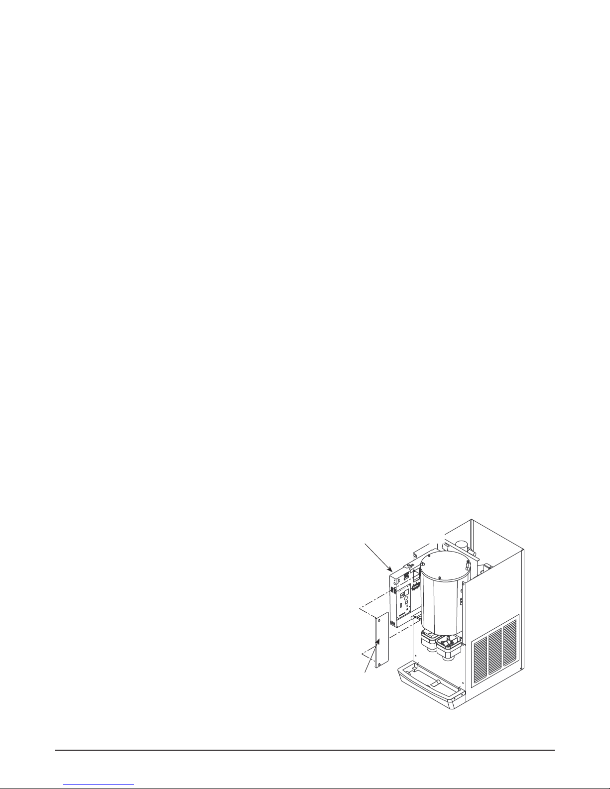
Access to electrical box and control board
The 12 series electrical box has been designed to slide out
for easy access to the control board and more convenient
troubleshooting.
1. Remove top and front panels of dispenser (for panel
removal instructions).
2. Remove electrical box cover.
3. Pull electrical box toward front of unit.
14 12CI400A • 12HI400A 220 V 60 Hz/230 V 50 Hz Dispensers
electrical box
electrical box
cover
Page 15
Wiring diagram – lever model
WTR PROBE
I.D.
LABEL
WATER SENSOR
L1
L2
POWER
DR
C
60M
20M
FAN
COMP
2ND
I.D.
WTR
SOFTWARE
B-T
DRV
B-E
RED #21
WHITE #15
SWITCH
COMPRESSOR
RED #20
VIOLET #22
VIOLET #23
ORANGE #14
BLACK #13
ORANGE #19
BIN
ORANGE #18
THERMO-
STAT
BIN SIGNAL SWITCH
BLUE
SAFETY SWITCH
HIGH PRESSURE
T.O.L.
RUN
START
GEAR MOTOR
BLACK
YELLOW
3
2
START
RELAY
4
WHITE
MOUNTED ON MAIN FRAME
x
ELEC. BOX
GRN IN
GREEN #27
x
MAIN FRAME
GRN TO
POWER SWITCH
RED #17
WHITE #16
RED 43
5
2
1
BLACK 45
Black
CAPACITOR
COMP. START
BLACK 47
RUN
R
BLACK 46
Silver
CAPACITOR
COMP. RUN
ORANGE 48
S
ORANGE 49
COMP. START RELAY
BLACK #38
WHITE #39
BLACK #10
COMPRESSOR
COMPONENTS
(INTERNAL)
OVER-LOAD
FAN
RED 42
MOUNTED ON
MAIN FRAME
WHITE 44
START
BLACK #8
WHITE #26
BLACK #9
Lid Interlock Sw.
C
BLACK #29
1
#28
BLACK
1
4
ICE DISPENSE
SWITCH
BLACK #31
#33
1
4
BLACK
#41
BLACK
BLACK
WHITE
#30
S
#32
WATER
4
WATER
DISPENSE
SWITCH
SOLENOID
ON SPLASH PANEL
COMPONENTS MOUNTED
COMPRESSOR
GREEN/YELLOW
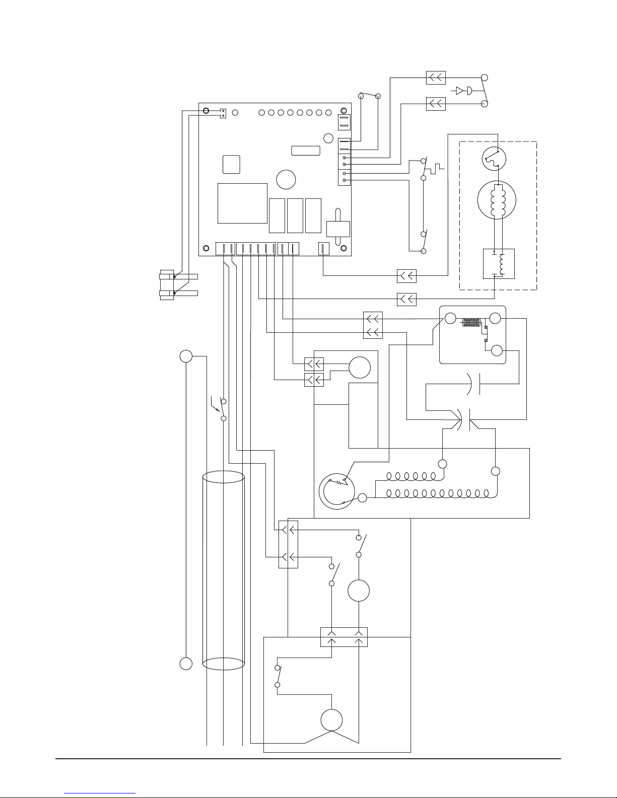
How the unit works — lever model
The dispense wheel motor is energized through the power, dispense and cover interlock switches. The bin signal circuit is completed through the normally closed
contacts of the bin thermostat and the bin signal switch. When ice builds up around the bin thermostat, the contacts open, cutting the bin signal circuit.
12CI400A • 12HI400A 220 V 60 Hz/230 V 50 Hz Dispensers 15
WHITE #34
M
MOTOR
BROWN
BLUE
WHEEL
MOUNTED ON
COMPONENTS
MAIN FRAME
NOTE
OPEN: 425psi CLOSES: 297psi (AUTORESET)
1. HIGH PRESSURE SAFETY SWITCH:
Page 16
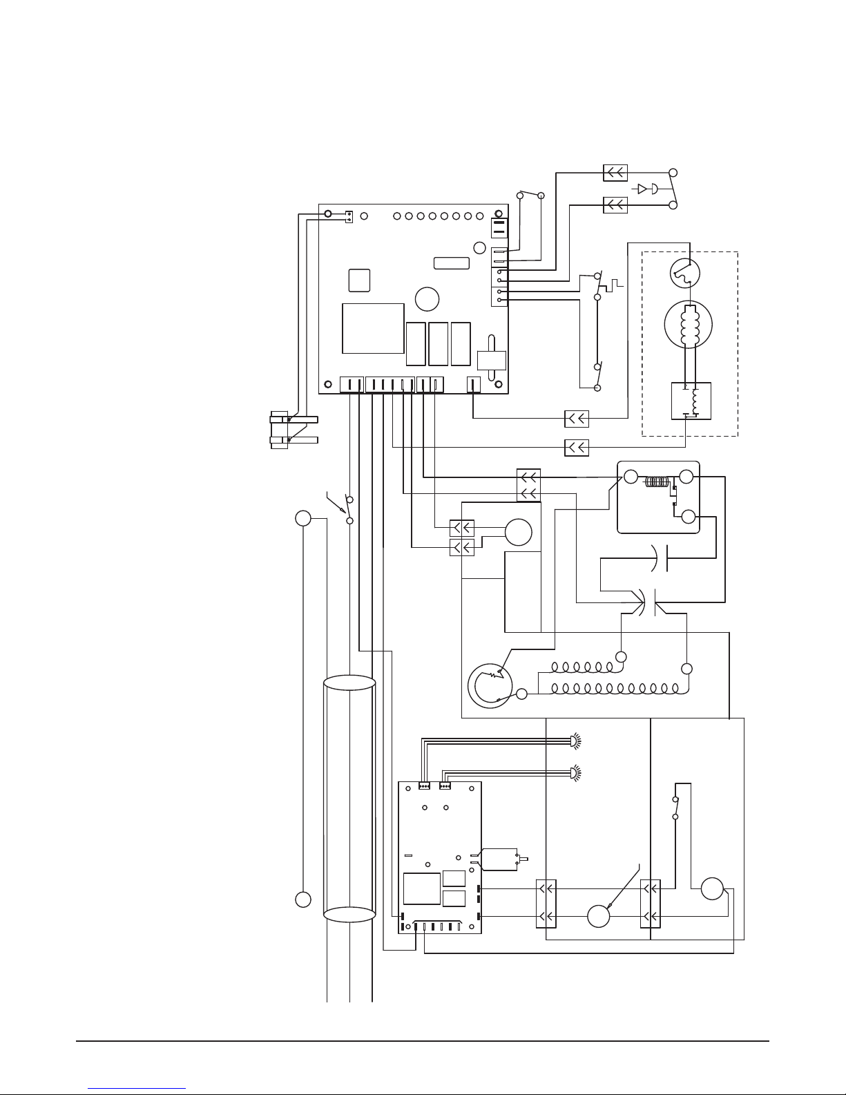
Wiring diagram – SensorSAFE model
DR
POWER
I.D.
LABEL
L2
WATER SENSOR
WTR PROBE
L1
C
20M
COMP
FAN
60M
2ND
WTR
I.D.
B-T
Compressor
Switch
SAFETY SWITCH
START
GEAR MOTOR
BLACK
2
START
RELAY
4
HIGH PRESSURE
T.O.L.
RUN
YELLOW
3
MOUNTED ON MAIN FRAME
RED 21
RED 20
BLACK #13
VIOLET 22
VIOLET 23
BIN
THERMO-
STAT
ORANGE 19
ORANGE 18
ORANGE 14
BIN SIGNAL SWITCH
BLUE
WHITE
B-E
SOFTWARE
DRV
WHITE #15
ELEC. BOX
GRN IN
GREEN #27
MAIN FRAME
GRN TO
WHITE 44
#36
RED 43
5
2
1
Black
CAPACITOR
BLACK 45
COMP. START
BLACK 47
RUN
R
Silver
ORANGE 48
START
BLACK 46
ORANGE 49
CAPACITOR
COMP. RUN
COMP. START RELAY
S
COMPRESSOR
ICE
SENSOR
COMPONENTS
MOUNTED ON
SENSOR
WATER
COMPONENTS
MOUNTED ON
SPLASH PANEL
4
1
LID INTERLOCK SWITCH
SOLENOID
WATER
BLACK #35
#37
S
BLACK
WHITE
BLACK #33
BLACK #41
MAIN FRAME
WHEELMOTOR
M
WHITE #34
RED #17
POWER SWITCH
BLACK #10
WHITE #16
x
BLACK #38
WHITE #39
BLACK #11
WHITE #12
COMPRESSOR
OPEN: 425psi CLOSES: 297psi (AUTORESET)
SEE LABEL FOR PROPER ORIENTATION
1. COMPRESSOR START RELAY IS GRAVITY SENSITIVE.
NOTE
2. HIGH PRESSURE SAFETY SWITCH:
ICE
WTR
GND
x
L1
PWR
NEUTRAL
CLN
WM
SOL
WTR
COMPONENTS
(INTERNAL)
OVER-LOAD
#40
YELLOW
#40
YELLOW
FAN
RED 42
MOUNTED ON
MAIN FRAME
C
4
1
CLEAN SWITCH
BLACK #8
BLACK #9
models provide “touchless” ice and water dispensing. When a container is placed within the actuation zone below the ice or water chute, an invisible, randomly-
™
How the unit works — SensorSAFE model
SensorSAFE
generated infrared signal is emitted, re ected off the container and detected by the sensor. The sensor then sends a signal to the control board to activate the appropriate
components to dispense ice or water. LEDs on the board indicate when the board is receiving a signal from the sensors.
A safety, shut-off feature automatically shuts off dispensing after one minute of continuous activation. Dispensing can be restarted by moving the container away and then
returning it to the actuation zone.
Dispensing can be temporarily suspended by depressing and releasing the clean switch, located under the left side of the top front cover. Depressing and releasing the button
a second time will return the dispenser to normal operating state. If the clean switch is not depressed a second time, the dispenser will automatically resume normal dispense
operation (CLN LED goes out) after two minutes. An LED on the control board will light to indicate that the dispensing has been suspended by activation of the clean switch.
The bin signal circuit is completed through the normally closed contacts of the bin thermostat and the bin signal switch. When ice builds up around the bin thermostat, the
contacts open, cutting the bin signal.
16 12CI400A • 12HI400A 220 V 60 Hz/230 V 50 Hz Dispensers
230 V~
50 Hz
WHITE #26
GREEN/YELLOW
BROWN
BLUE
Page 17
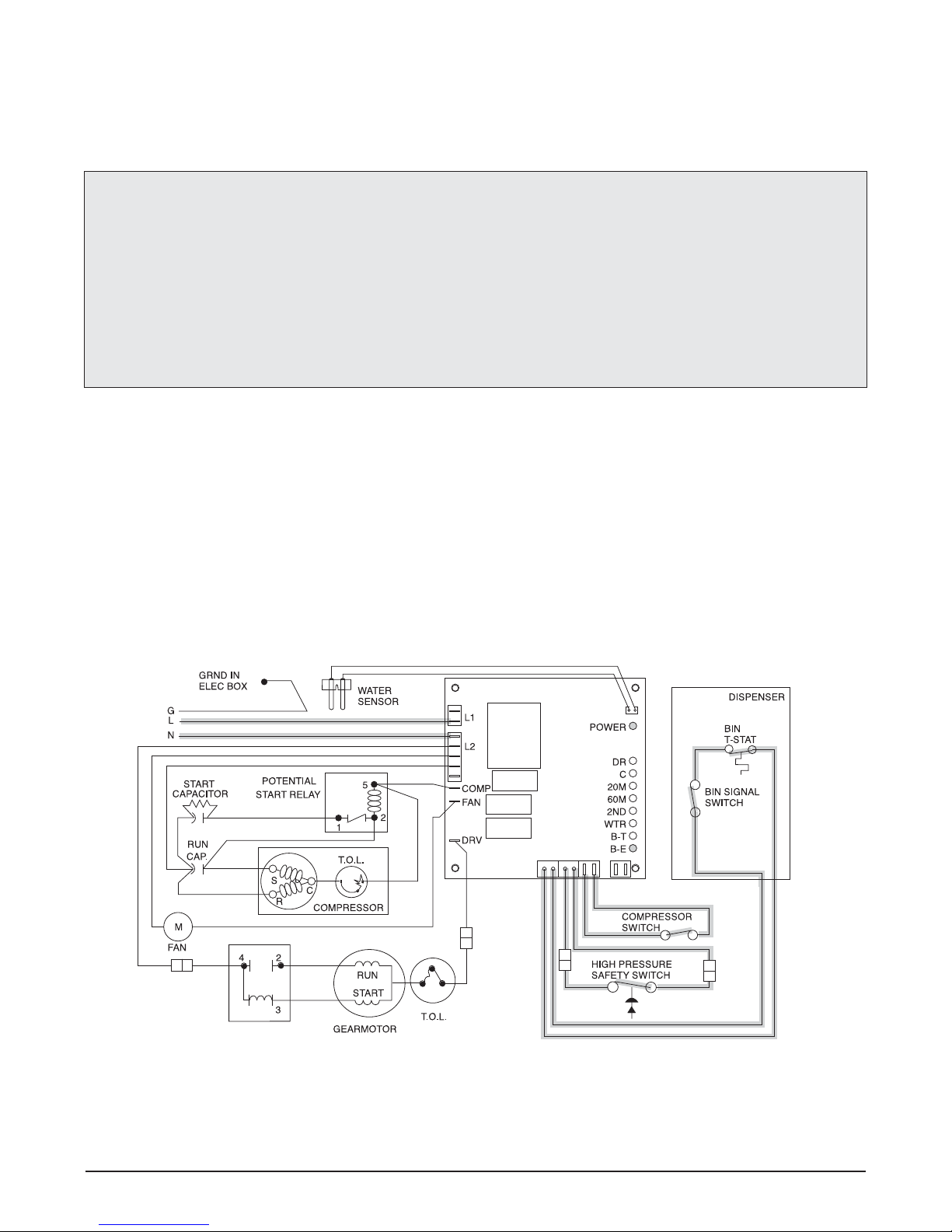
Ice machine operational and diagnostic sequences
The wiring diagrams that follow illustrate the circuitry of Follett ice machines used with 12 series ice
dispensers. Both normal operation (Stages 1 – 6) and non-normal diagnostic sequences showing torque-out
(Stages 7 – 10) for use in troubleshooting are shown.
Circuitry notes
• Compressor switch should read closed in ON position.
• Bin signal is 16V DC.
• Flashing water LED at any time indicates that water signal to board has been lost for more than one second.
• Ten-second delay: There is a 10 second delay in reaction to loss of water (WTR) or bin (B-E) signals. If
signals are not lost for more than 10 seconds, no reaction will occur.
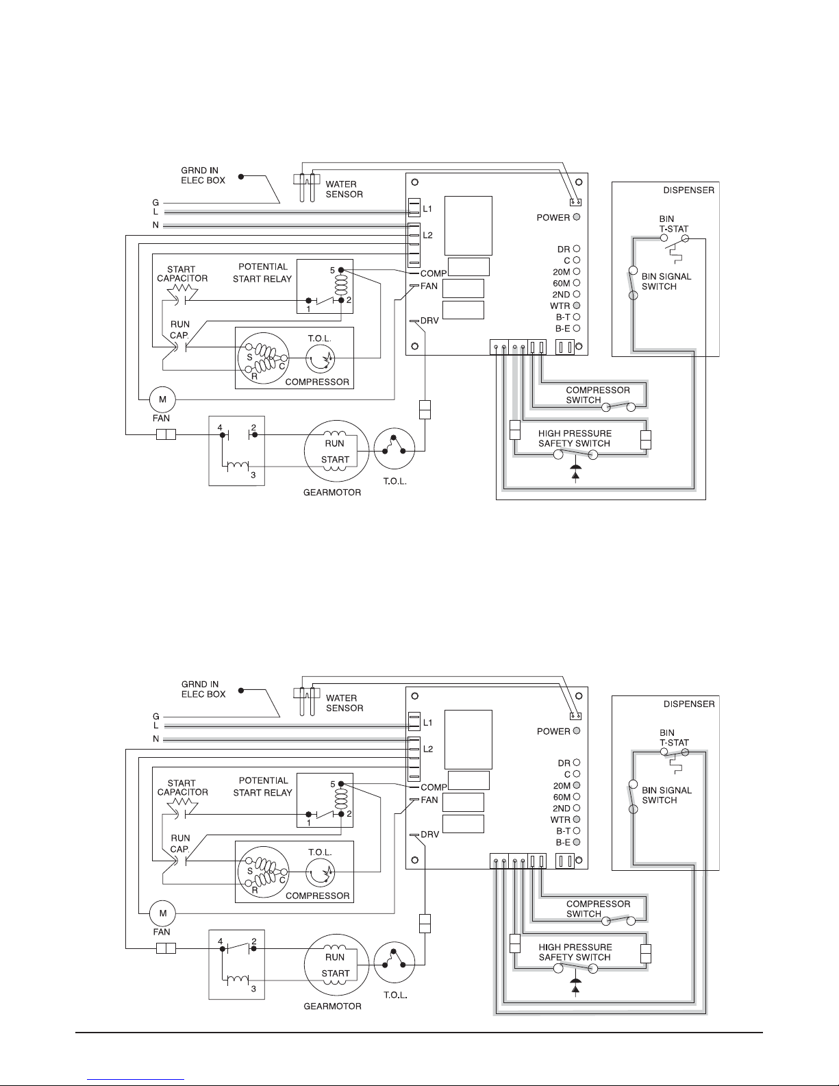
Normal operation – Stage 1
Power is supplied to L1 of the control board. The ice level control in the dispenser is closed and calling for ice,
completing the bin signal circuit to the control board. The control board will now go through the start-up sequence.
Less than 30 seconds will elapse as the water sensor located in the oat reservoir checks for water in the
reservoir. The bin empty LED (B-E), and power LED (PWR) will be on.
GREEN/YELLOW
BROWN
BLUE
BLACK
BLACK
WHITE
ORANGE
ORANGE
WHITE
WHITE
BLACK
WHITE
BLACK
BLACK
YELLOW
RED
RED
BLACK
BLACK
BLUE
ORANGE
ORANGE
VIOLET
BLACK
VIOLET
RED
RED
BLACK
12CI400A • 12HI400A 220 V 60 Hz/230 V 50 Hz Dispensers 17
Page 18
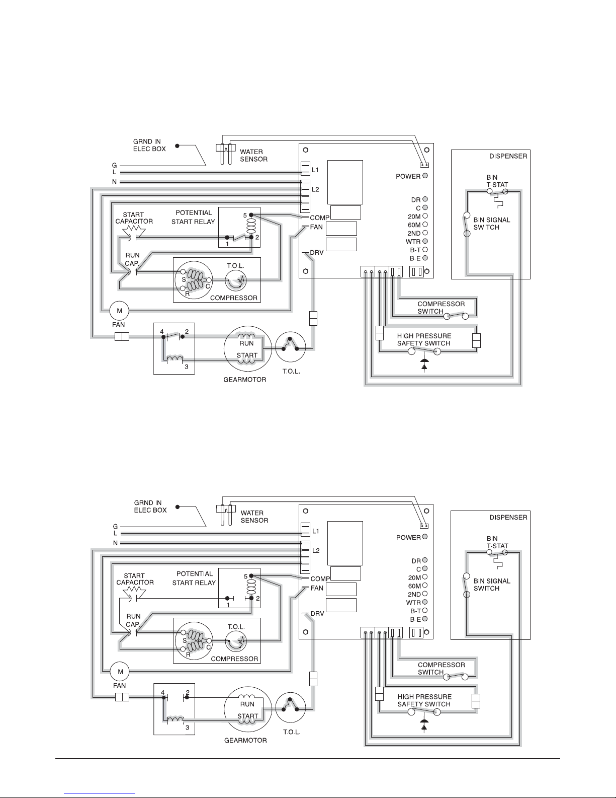
Normal operation – Stage 2
The water sensor veri es water in the oat reservoir. The water OK LED (WTR) comes on. At the same time, the
gearmotor, compressor and condenser fan motor come on, lighting the drive LED (DR) and compressor LED (C).
The gearmotor is started through a current style relay that is pulled in by the initial high current draw of the run
winding. The compressor is started with the start winding being energized through the normally closed contacts of
the potential relay, starting capacitor, and the run capacitor. The PWR, BE and WTR LED remain on.
GREEN/YELLOW
BROWN
BLUE
BLACK
BLACK
ORANGE
ORANGE
WHITE
BLACK
WHITE
BLACK
RED
RED
BLACK
BLACK
ORANGE
ORANGE
VIOLET
VIOLET
RED
RED
BLUE
BLACK
BLACK
WHITE
WHITE
BLACK
YELLOW
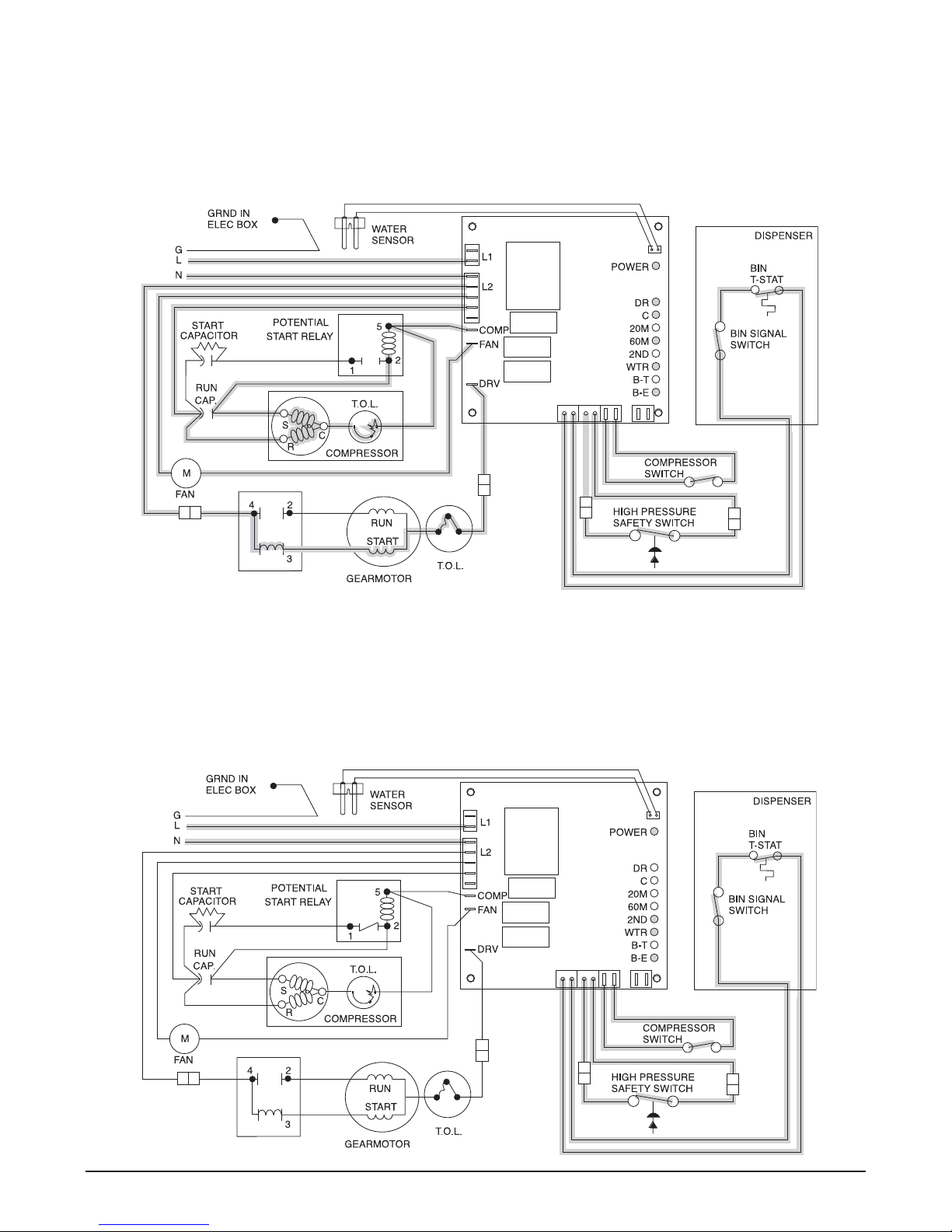
Normal operation – Stage 3
After the initial high current draw drops off, the gearmotor start relay contacts open, dropping out the start winding.
As the compressor comes up to normal running speed, the compressor start relay contacts open and the starting
capacitor drops out. The start winding remains energized through the run capacitor. The ice machine is now in a
normal icemaking mode. The ice machine will begin to produce ice and continue to produce ice until the bin level
control in the ice dispenser is satis ed. The PWR, B-E, DR, C and WTR LEDs are all on.
GREEN/YELLOW
BROWN
BLUE
BLACK
BLACK
ORANGE
ORANGE
WHITE
BLACK
WHITE
BLACK
RED
RED
BLACK
ORANGE
ORANGE
VIOLET
VIOLET
RED
RED
BLACK
WHITE
WHITE
YELLOW
18 12CI400A • 12HI400A 220 V 60 Hz/230 V 50 Hz Dispensers
BLACK
BLUE
BLACK
BLACK
Page 19
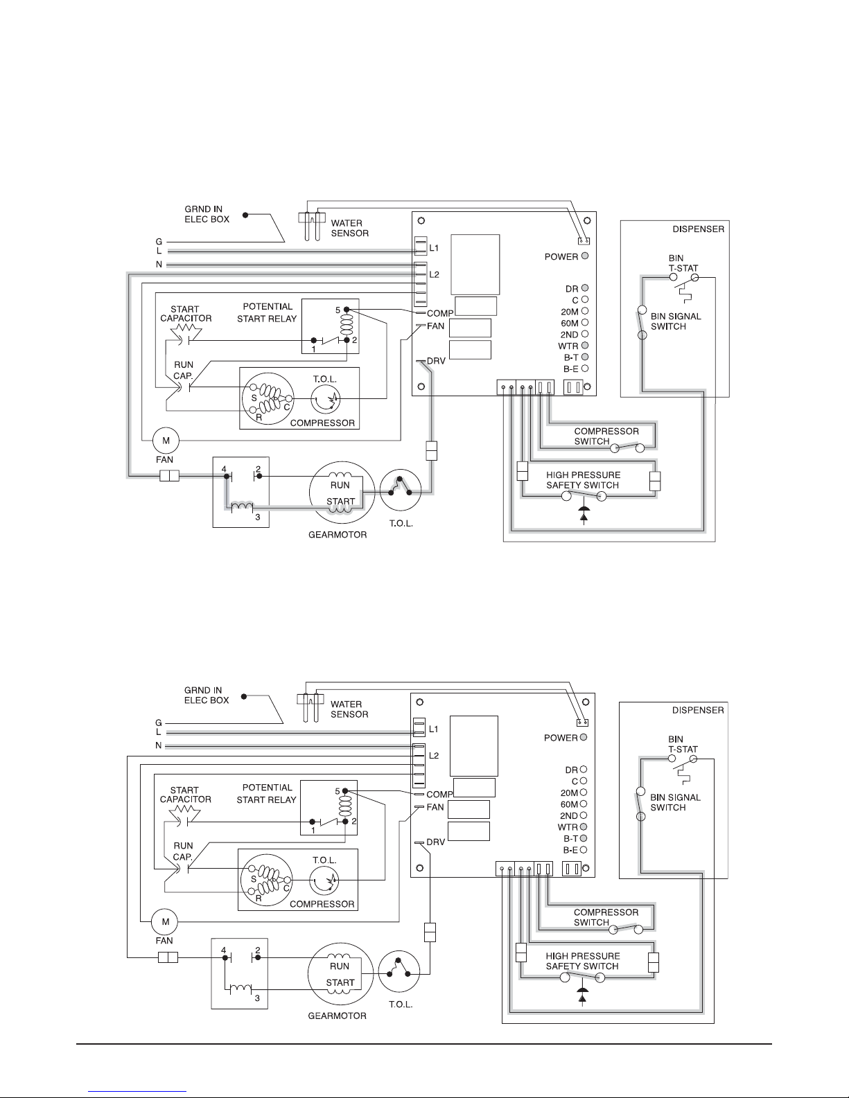
Normal operation – Stage 4
Once the ice level control opens, the B-E LED goes out. After a 10 second delay the compressor LED (C),
compressor and fan motor go off. (Should the ice level control not remain open for 10 seconds, the ice machine
will continue to run.) The gearmotor continues to run and the DR LED remains on for 60 seconds. The purpose
of this function is to drive the remaining ice out of the evaporator and to boil off any refrigerant remaining in the
evaporator. The bin timer LED (BT) comes on, starting the twenty minute off cycle time delay.
GREEN/YELLOW
BROWN
BLUE
BLACK
BLACK
ORANGE
ORANGE
WHITE
BLACK
WHITE
BLACK
RED
RED
BLACK
BLACK
ORANGE
ORANGE
VIOLET
VIOLET
RED
RED
BLUE
BLACK
BLACK
WHITE
WHITE
BLACK
YELLOW
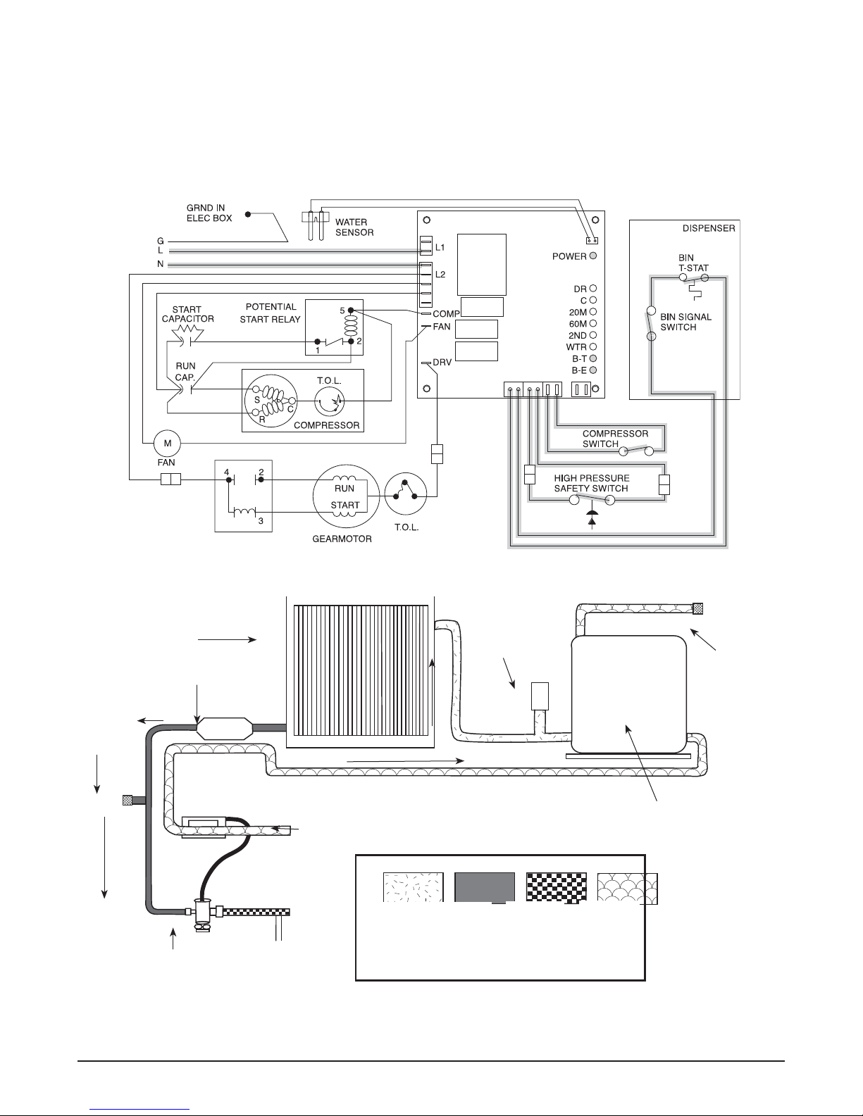
Normal operation – Stage 5
The drive motor now shuts down and the DR LED is off. The B-T LED remains on for 20 minutes. The ice machine
will not start while the B-T LED is on. To restart the ice machine for troubleshooting purposes, depress the reset
button to clear the control board.
GREEN/YELLOW
BROWN
BLUE
BLACK
BLACK
ORANGE
ORANGE
WHITE
BLACK
WHITE
BLACK
RED
RED
BLACK
ORANGE
ORANGE
VIOLET
VIOLET
RED
RED
BLACK
WHITE
WHITE
YELLOW
12CI400A • 12HI400A 220 V 60 Hz/230 V 50 Hz Dispensers 19
BLACK
BLUE
BLACK
BLACK
Page 20
Normal operation – Stage 6
When the dwell time of 20 minutes has expired, the B-T LED goes off. The ice machine goes through the normal
start-up sequence when the bin level control signals the control board for ice. The WTR LED will remain on as
long as the water sensor in the oat reservoir senses water.
GREEN/YELLOW
BROWN
BLUE
BLACK
BLACK
ORANGE
ORANGE
WHITE
BLACK
WHITE
BLACK
RED
RED
BLACK
BLACK
ORANGE
ORANGE
VIOLET
VIOLET
RED
RED
BLUE
BLACK
BLACK
WHITE
WHITE
BLACK
YELLOW
Diagnostic sequence – Stage 7
The 20 minute error LED (20M) is on, indicating that the control board has sensed an over-torque condition
(above 2.5 AMPS on the gearmotor). The 20M LED remains on for 20 minutes after an over-torque condition has
occurred. The ice machine remains off as long as the 20M LED is on. When the 20M LED goes off, the control
board will try to go through a normal start-up sequence. The WTR LED remains on as long as the water sensor in
the oat reservoir senses water.
GREEN/YELLOW
BROWN
BLUE
BLACK
BLACK
ORANGE
ORANGE
WHITE
BLACK
WHITE
BLACK
RED
RED
BLACK
ORANGE
ORANGE
VIOLET
VIOLET
RED
RED
BLACK
WHITE
WHITE
YELLOW
20 12CI400A • 12HI400A 220 V 60 Hz/230 V 50 Hz Dispensers
BLACK
BLUE
BLACK
BLACK
Page 21
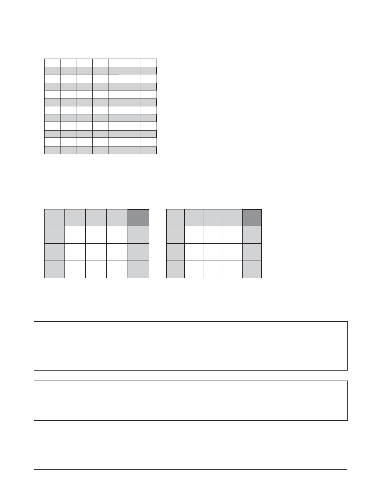
Diagnostic sequence – Stage 8
If the restart is successful the 20M LED goes off, the 60 minute timer LED (60M) comes on. The 60M LED will
remains on for 60 minutes from restart. A lighted 60M LED indicates the ice machine has experienced an overtorque condition. If the ice machine runs without problems for 60 minutes and no additional torque errors occur,
the 60M LED goes off and the ice machine continues normal operation.
GREEN/YELLOW
BROWN
BLUE
BLACK
BLACK
ORANGE
ORANGE
WHITE
BLACK
WHITE
BLACK
RED
RED
BLACK
BLACK
ORANGE
ORANGE
VIOLET
VIOLET
RED
RED
BLUE
BLACK
BLACK
WHITE
WHITE
BLACK
YELLOW
Diagnostic sequence – Stage 9
The second error (2ND) LED comes on if an over-torque condition occurs while the 60M LED is still lit. The 2ND
LED indicates two consecutive over-torque situations have occurred. The ice machine will be shut down at this
time and will not restart unless the manual reset button is depressed.
GREEN/YELLOW
BROWN
BLUE
BLACK
BLACK
ORANGE
ORANGE
WHITE
BLACK
WHITE
BLACK
RED
RED
BLACK
ORANGE
ORANGE
VIOLET
VIOLET
RED
RED
BLACK
WHITE
WHITE
YELLOW
12CI400A • 12HI400A 220 V 60 Hz/230 V 50 Hz Dispensers 21
BLACK
BLUE
BLACK
BLACK
Page 22
Diagnostic sequence – Stage 10
If the water level in the oat reservoir drops to an unacceptable level, the WTR LED goes out, shutting the ice
machine off. Also, the BT LED comes on, preventing the ice machine from restarting for twenty minutes. If water
is restored, the WTR LED comes back on and ashes to alert the technician that water to ice machine has been
lost. The ice machine restarts at the end of the 20 minute time delay. The ashing WTR LED can be cleared by
pressing the reset button.
GREEN/YELLOW
BROWN
BLUE
BLACK
BLACK
ORANGE
ORANGE
WHITE
BLACK
WHITE
BLACK
RED
RED
BLACK
BLACK
ORANGE
ORANGE
VIOLET
VIOLET
RED
RED
WHITE
Refrigeration cycle
condenser
lter dryer
high side
service
port
WHITE
BLACK
YELLOW
evaporator
BLUE
high pressure
switch
BLACK
BLACK
low side service
port
compressor
thermostatic expansion valve
22 12CI400A • 12HI400A 220 V 60 Hz/230 V 50 Hz Dispensers
high
pressure
vapor
high
pressure
liquid
low pressure
liquid
low pressure
vapor
Page 23
Refrigeration pressure data
Air-cooled icemaker capacity/24 hrs.
Ambient Air Temperature ˚F/˚C
60
70
80
90
32
317
144
298
135
280
127
271
123
262
119
100
38
268
122
243
110
217
98
214
97
210
95
F
16
21
417
189
402
182
387
176
369
175
351
159
27
366
166
354
161
342
155
328
149
314
142
C
468
50
212
10
450
60
204
16
432
70
196
21
410
80
186
27
387
90
176
32
Inlet Water Temperature ˚F/˚C
Air-cooled Icemaker
Refrigeration Pressure
Discharge Pressure/Suction Pressure
lbs.
kg.
lbs.
kg.
lbs.
kg.
lbs.
kg.
lbs.
kg.
Ambient Air Temperature C
C
10
21
32
Iinlet water temperature C
16
12/1.6
12/1.6
13.1/1.7
27
16.9/2.1
16.8/2.1
18.3/2.2
38
16.3/2.5
22.5/2.6
23.9/2.8
bar
bar
bar
Ambient Air Temperature F
60
F
174/23
50
174/23
70
190/25
90
Iinlet water temperature F
245/31
244/30
265/32
80
100
237/37
326/38
347/40
psi
psi
psi
Table 2 – Compressor data
Compressor current draw
Air-cooled
Ambient air temp. 15.6 C/60 F 21.1 C/70 F 26.7 C/80 F 32.2 C/90 F 37.8 C/100 F
3.2A 3.3A 3.4A 3.5A 3.6A
Locked rotor amps 26.3
Table 3 – Gearmotor data
Gearmotor current 1.3A (nominal)
Locked rotor amps 6.8 amps
12CI400A • 12HI400A 220 V 60 Hz/230 V 50 Hz Dispensers 23
Page 24
Refrigeration system
Important: All service on refrigeration system must be performed in accordance with all federal, state and
local laws that pertain to the use of refrigerants. It is the responsibility of the technician to ensure that these
requirements are met.
Ice machine charge speci cations
Model Charge Refrigerant type
C/E12CI400A, C/E12HI400A (air-cooled) 540g (19 oz) R404A
Recharging of unit at other than factory speci cations will void ice machine warranty.
!
Refrigerant replacement requirements
1. Non-contaminated refrigerant removed from any Follett refrigeration system can be recycled and returned to
the same system after completing repairs. Recycled refrigerant must be stored in a clean, approved storage
container. If additional refrigerant is required, virgin or reclaimed refrigerant that meets ARI standard 700-88
must be used.
2. In the event of system contamination (for example, a compressor burn out, refrigerant leak, presence of noncondensibles or moisture), the system must be repaired, evacuated and recharged using virgin or reclaimed
refrigerant that meets ARI standard 700-88.
3. Follett Corporation does not approve of recovered refrigerants. Improper refrigeration servicing procedures
will void the factory warranty.
Evacuation
Evacuate the system to a level of 500 microns. When the 500 micron level is reached, close valves and both
manifold and shut down the vacuum pump. Allow the system to sit for approximately 20 minutes. During this period
the system pressure should not rise. If the system pressure rises and stabilizes there is moisture in the system
and further evacuation is needed. If the pressure continues to rise check the system for leaks.
Ambients Minimum Maximum
Air temperature1 10 C/50 F 37.8 C/100 F
Water temperature2 4.4 C/40 F 32.2 C/90 F
1 Ambient air temperature is measured at the air-cooled condenser coil inlet.
2 Ambient water temperature is measured in the ice machine oat reservoir.
24 12CI400A • 12HI400A 220 V 60 Hz/230 V 50 Hz Dispensers
Page 25
Ice capacity test
Ice machine production capacity can only be determined by weighing ice produced in a speci c time period.
1. Remove top panel and hopper lid of unit.
2. Weigh and record weight of container used to catch ice.
3. Run ice machine for at least 15 minutes.
4. Catch ice for 15 or 20 minutes.
5. Weigh harvested ice and record total weight.
6. Subtract weight of container from total weight.
7. Convert fractions of pounds to decimal equivalents (Ex. 6 lbs 8 oz = 6.5 lbs).
8. Calculate production using following formula:
1440 min. × wt. of ice produced
Total test time in minutes
9. Calculated amount per 24 hours should be checked against rated capacity for same ambient and water
temperatures in Ice Production Table (see page 23).
production capacity/
=
24 hr. period
Dispenser troubleshooting
Disconnect power to unit before putting hands or arms in storage area or attempting any
!
Before calling for service:
• Check that no ice is in the dispenser bin are
• Check that all switches and circuit breakers are on
• Check that congealed ice is not causing a jam
• Check that all drains are clear
Lever model troubleshooting guide
Problem Indicators Corrective Action
Does not dispense ice. 1. Power switch off or faulty.
Dispense wheel rotates
continuously.
Ice machine runs continuously. Faulty or incorrectly positioned bin
Does not dispense water. 1. Faulty water solenoid valve.
repair or service to equipment.
2. Faulty dispense switch.
3. Wheel motor malfunction.
Dispense switch contacts are burned
out.
stat.
2. Faulty dispense switch.
3. Power switch off or faulty.
1. Check switch – turn on or replace
if faulty.
2. Replace switch.
3. Check motor and capacitor and
replace
Replace dispense switch.
Check for proper positioning. If stat
does not open when ice is placed on
capillary tube, replace stat.
1. Replace water solenoid valve.
2. Replace dispense switch.
3. Check switch - turn on or replace if
faulty.
12CI400A • 12HI400A 220 V 60 Hz/230 V 50 Hz Dispensers 25
Page 26
SensorSAFE model troubleshooting guide
SensorSAFE Board LED
Status
ICE/
Problem Action
Does not
dispense ice
and/or water.
Dispenses ice
and/or water
continuously.
Check
LEDs on the
SensorSAFE
control board.
Place cup
under drop
zone (in front
of lens)
Check LEDs
on control
board.
Board guide
OFF OFF OFF Check circuit breakers and power switch.
ON ON OFF Press clean switch on lower left side of electrical
ON OFF OFF Troubleshoot appropriate lens/sensor
ON OFF ON Verify power on appropriate output terminal
ON OFF ON Troubleshoot appropriate lens/sensor
ON OFF OFF If there is power on any output terminal 9WTR
WTR
Corrective ActionPWR CLN
Restore power or replace defective switch.
enclosure to return board to normal operation.
and replace if required (see lens/sensor
troubleshooting).
(WTR or WM) on control board and replace
board if required. If board tests okay,
troubleshoot appropriate dispenser component.
and replace if required (see lens/sensor
troubleshooting).
or WM) on control board, replace board.
LEDs, when illuminated, indicate the following: PWR (board power), CLN (cleaning, no dispensing cycle), ICE
(ice dispensing activated), WTR (water dispensing activated).
Terminals: LI (incoming power, hot), L2 (neutral terminals), WTR (power terminal for water solenoid), WM (power
terminal for wheelmotor), CLN (terminals for clean cycle switch).
Note: SOL terminal not used in 12 series dispensers.
Lens/sensor troubleshooting
1. Turn dispenser power switch off and remove slash panel.
2. Disconnect wires from WTR and WM terminals on board.
3. Gently remove sensor/mounting block from splash panel.
4. Inspect lens and sensor, clean if necessary.
5. Restore dispenser power and test sensor by passing hand in front of sensor.
6. If LED on board turns on, sensor is operational. Re-assemble dispenser.
7. If LED does not come on switch sensor leads on board and retest.
8. If opposite Led comes on – replace defective board.
9. If opposite Led does not come on – replace defective sensor.
26 12CI400A • 12HI400A 220 V 60 Hz/230 V 50 Hz Dispensers
Page 27

Ice machine troubleshooting
Flashing water LED at any time indicates that water signal to board had been lost for more than one second.
Ten-second delay: There is a 10 second delay in reaction to loss of water (WTR) or bin (B-E) signals. If signals
are not lost for more than 10 seconds, no reaction will occur.
Problem Indicators Corrective Action
Ice machine will not
run.
System status:
compressor,
gearmotor, and fan
motor inoperative.
Compressor will not
run.
System status:
gearmotor and fan
motor run.
Unit cycles
intermittently.
System status:
compressor, gearmotor,
and fan motor cycle.
Low ice production.
Poor quality ice.
Water leaks
from bottom of
evaporator.
Ice machine runs for
short period of time
and shuts down on
torque error.
System status: 20M or
2nd LED is lit.
Evaporator is iced up
on the outside. No ice
production.
System status:
compressor, gearmotor
and fan motor running.
1. No power to unit.
2. Open bin level control.
3. Water OK LED (WTR) not on.
4. 20M or 2ND LED is on indicating that rst or
second torque error has occurred.
5. Gear motor locked up (immediate torque error
indicated by LEDs when board is reset).
6. Open coil on gearmotor start relay causing an
immediate torque error.
1. Condenser coil plugged causing open overload or
high pressure cut-out.
2. Defective starting capacitor.
3. Defective starting relay.
4. Open motor winding.
5. No power output from compressor output terminal
on control board.
1. Float reservoir running dry, sensing probe
signalling for system to shut down.
1. Dirty air lter or condenser coil.
2. Restricted air ow to condenser coil.
3. Mineral coated evaporator.
4. Improper exhaust air provisions.
5. Faulty expansion valve.
6. Low refrigerant charge.
7. Superheat incorrect.
8. Inefficient compressor.
1. O ring seal broken. 1. Replace O ring.
1. Kink in ice transport tube.
2. Bin level control remains in closed position.
3. Ice transport tube ruptured internally.
4. Worn evaporator bearings.
5. Faulty gearmotor start relay. Ice machine torques
out within 5 seconds of start-up.
6. Torque out occurs when storage bin lls to capacity.
1. Gearmotor running but no output rotation.
2. Float reservoir empty.
3. Air bubble in water supply line. Water
in reservoir but not in evaporator.
1. Check that unit is plugged in, circuit breakers are on.
2. Adjust or replace ice level control.
3. Check reservoir for water, restore water to unit.
4. See #6 below.
5. Repair or replace gearmotor.
6. Replace gearmotor start relay.
1. Clean condenser coil and replace overload if
necessary.
2. Replace start capacitor.
3. Replace relay.
4. Ohm out windings and replace compressor if
necessary.
5. Check terminal connection and replace control board
if necessary.
1. Check water supply to oat and oat operation. PC
board will have ashing WTR LED.
1. Clean or replace lter, clean condenser.
2. Remove obstruction.
3. Clean evaporator.
4. Provide proper exhaust air provisions per Follett
installation manual.
5. Replace expansion valve.
6. Check for leaks; repair, evacuate, and weigh in correct
charge.
7. Check that TXV sensing bulb is securely clamped in
place and not damaged; check that insulated bulb
cover is in place.
8. Replace compressor.
1. Eliminate kink and check that tube routing complies
with Follett ice machine installation manual.
2. Adjust or replace control.
3. Replace complete length of ice transport tube.
4. Inspect bearings for roughness or binding and replace
if necessary.
5. Replace gearmotor start relay.
6. Ensure that ice contacts bin thermostat before
backing ice up in transport tube. Refer to dispenser
manual for proper thermostat and ice tube mounting.
1. Check for broken gearmotor output shaft or damaged
gearbox.
2. Check for defective water sensor (water OK (WTR)
LED remains on even when oat empty or probe
removed from water).
3. Purge air from line.
12CI400A • 12HI400A 220 V 60 Hz/230 V 50 Hz Dispensers 27
Page 28
Problem Indicators Corrective Action
Compressor cycles
intermittently.
System status:
gearmotor and fan
motor run.
Unit runs but not
making ice.
System status:
compressor, gearmotor
& fan motor running.
Compressor and fan
motor will not run.
Gearmotor runs.
Intermittent noises from
evaporator.
1. Compressor start relay in wrong position.
2. High pressure cutout open due to high head
pressure.
3. Clogged or dirty air lter or condenser coil.
4. Improper ventilation.
5. Defective compressor.
1. Clogged or dirty air lter or condenser coil.
2. Compressor not pumping.
3. Low refrigerant charge.
1. Compressor switch in OFF position.
2. No output on compressor and fan motor terminals
on control board.
3. Failed fan motor causes high pressure cut-out to
open.
1. Mineral build-up on evaporator surface. 1. Clean evaporator with liquid ice machine cleaner.
1. Position relay with arrow or word “top”.
2. Check discharge pressure and adjust water regulator
valve.
3. Clean or replace lter, clean condenser coil.
4. Provide inlet and exhaust air provisions per Follett ice
machine installation manual.
5. Replace compressor.
1. Clean or replace lter, clean condenser coil.
2. Replace compressor.
3. Check for leaks; repair, evacuate, and weigh in correct
charge.
1. Turn compressor switch on.
2. Replace control board.
3. Replace fan motor.
28 12CI400A • 12HI400A 220 V 60 Hz/230 V 50 Hz Dispensers
Page 29
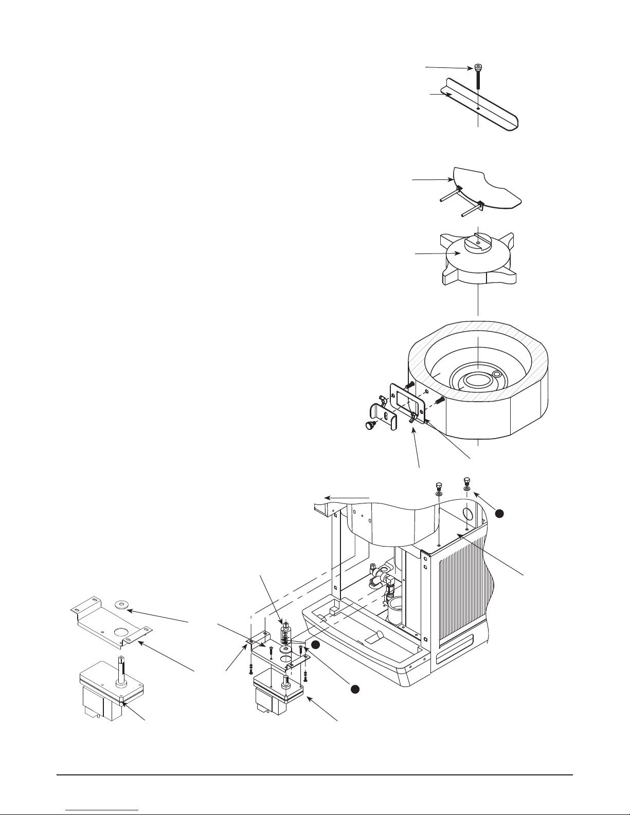
Disassembly and replacement instructions
Dispense chute removal
1. Remove top cover (see page 31).
2. Remove stainless front cover (see page 31).
3. Slide plastic dispense chute cover up and out to remove.
4. Remove four (4) push fasteners holding dispense tube in
place and remove tube.
Dispense wheel and drive bar removal
1. Remove all ice from storage area of dispenser.
2. Remove center thumbscrew, locking plate, two wingnuts
and backing plate from front of storage hopper (see drawing
at right).
3. Remove threaded rod, agitator, baffle, and wheel in this
sequence.
Wheelmotor removal
1. Remove dispense wheel and drive bar (see above).
2. Remove four (4) hopper/support plate mounting screws and
washers (Fig. 11.1).
3. Move hopper assembly 1/2" (13mm) to left.
4. Remove four (4) dispenser motor bracket mounting screws
and washers (Fig. 11.2).
5. Short shaft motors only: loosen only two (2) lower screws
on drive coupling and remove from motor shaft (Fig. 11.3).
6. Remove four (4) screws holding motor to mounting bracket.
threaded rod
agitator
baffle
dispense wheel
Fig. 11
MOVE HOPPER ASSEMBLY 13mm (1/2") TO LEFT
drive coupling assembly
shield
3
mounting
bracket
dispense motor (long shaft, current)
wingnut
2
dispense motor mounting screws
dispense motor (short shaft)
backing plate
1
mounting
screw &
washer
hopper/
support
plate
assembly
12CI400A • 12HI400A 220 V 60 Hz/230 V 50 Hz Dispensers 29
Page 30
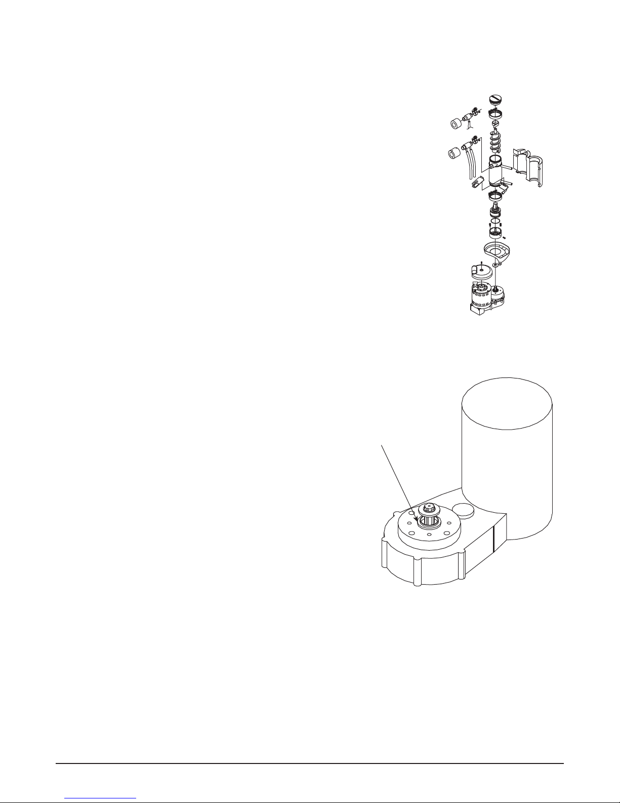
Evaporator disassembly
Note: The upper bearing, lower bearing and auger assemblies must be replaced as assemblies. The bottom and
top bearing assemblies cannot be eld assembled to factory speci cations.
1. Disconnect power to ice machine.
2. Shut off water to ice machine.
3. Drain evaporator and oat tank.
4. Disconnect plastic tubing from evaporator water inlet, drain pan stub,
compression nozzle tubing and reservoir over ow tubing from secured clip.
5. Disconnect ice transport tube from compression nozzle.
6. Remove nut and upper vee band coupling from top of evaporator
7. Lift top bearing assembly straight up with a slight rotating motion and remove.
8. Remove ice compression loop located at top of auger.
9. Lift auger straight up and out of evaporator.
10. Remove nut and lower vee band coupling from bottom of evaporator.
11. Lift evaporator to clear bottom bearing assembly.
12. Loosen hex head bolt in side of mounting base with 8mm (5/16") wrench and
lift lower bearing assembly.
13. Remove condensate shield.
14. Remove 4 Allen head machine screws holding mounting base to gearbox.
15. If replacing evaporator, remove compression nozzle from evaporator port.
Evaporator reassembly
1. Clean gearmotor boss, output shaft and shaft well.
2. Install drain pan and evaporator mounting base.
3. Fill gear motor shaft well with food grade grease.
4. Install condensate shield and seat against gear motor boss.
5. Install bearing O ring in groove in evaporator mounting base.
6. Lower bottom bearing assembly into evaporator mounting base.
7. While maintaining a slight downward pressure on bottom bearing
Apply grease
in well
assembly, tighten hex head bolt with a 8mm (5/16") wrench.
8. Position evaporator over lower bearing assembly and align
grooves with pins in bearing assembly.
9. Install vee band clamp and nut to 8.05mm/kg (70 in/lb).
10. Place auger in center of evaporator and rotate to mate with drive
pin.
11. Install ice compression loop, orienting loop.
12. Install upper bearing and seal assembly, rotating bearing to slip
pin into auger slot.
13. Install upper vee band clamp and nut to 8.05mm/kg (70 in/lb).
14. If evaporator was replaced, reinstall compression nozzle on new.
Gearmotor replacement
1. Disassemble evaporator as described above.
2. Disconnect the wire connectors.
3. Remove four screws holding gear motor mounting plate to base of ice machine and lift gearbox and motor
clear of ice machine.
4. Remove machine screws holding mounting plate to motor.
5. Install new motor in reverse order.
30 12CI400A • 12HI400A 220 V 60 Hz/230 V 50 Hz Dispensers
Page 31
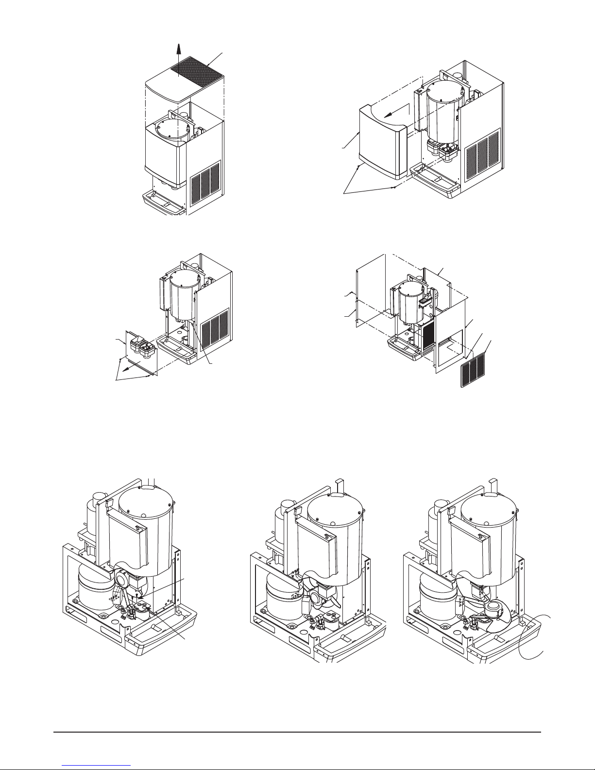
top cover
Panel removal
front cover
screw
Top cover: Lift cover up and off Velcro strips.
splash panel
hopper support lip
screw
Splash panel: Remove 2 screws. Pull out bottom
of panel to allow top to slide out from under hopper
support lip.
Fan removal
Front cover: Remove 2 screws. Lift cover up and
forward to unhook from keyhole slots and clear tabs on
bottom of cover.
back panel
screw
LH side
panel
RH side panel
screw
louver
panel
Side panels: Remove screw located on lower rear
side. Pull side panel toward front of unit and out of back
panel. Note: Before removing right hand side, remove
side louver panel by lifting up and pulling forward on
panel.
mounting
screws
drain tube
bracket
(a) Remove 4 fan mounting screws
and 3 drain tubes from bracket.
12CI400A • 12HI400A 220 V 60 Hz/230 V 50 Hz Dispensers 31
(b) Rotate fan mounting bracket
toward back of unit and pull
fan assembly toward front
ofunit.
(c) As fan assembly is being pulled
toward front, rotate assembly
clockwise as shown above.
Page 32
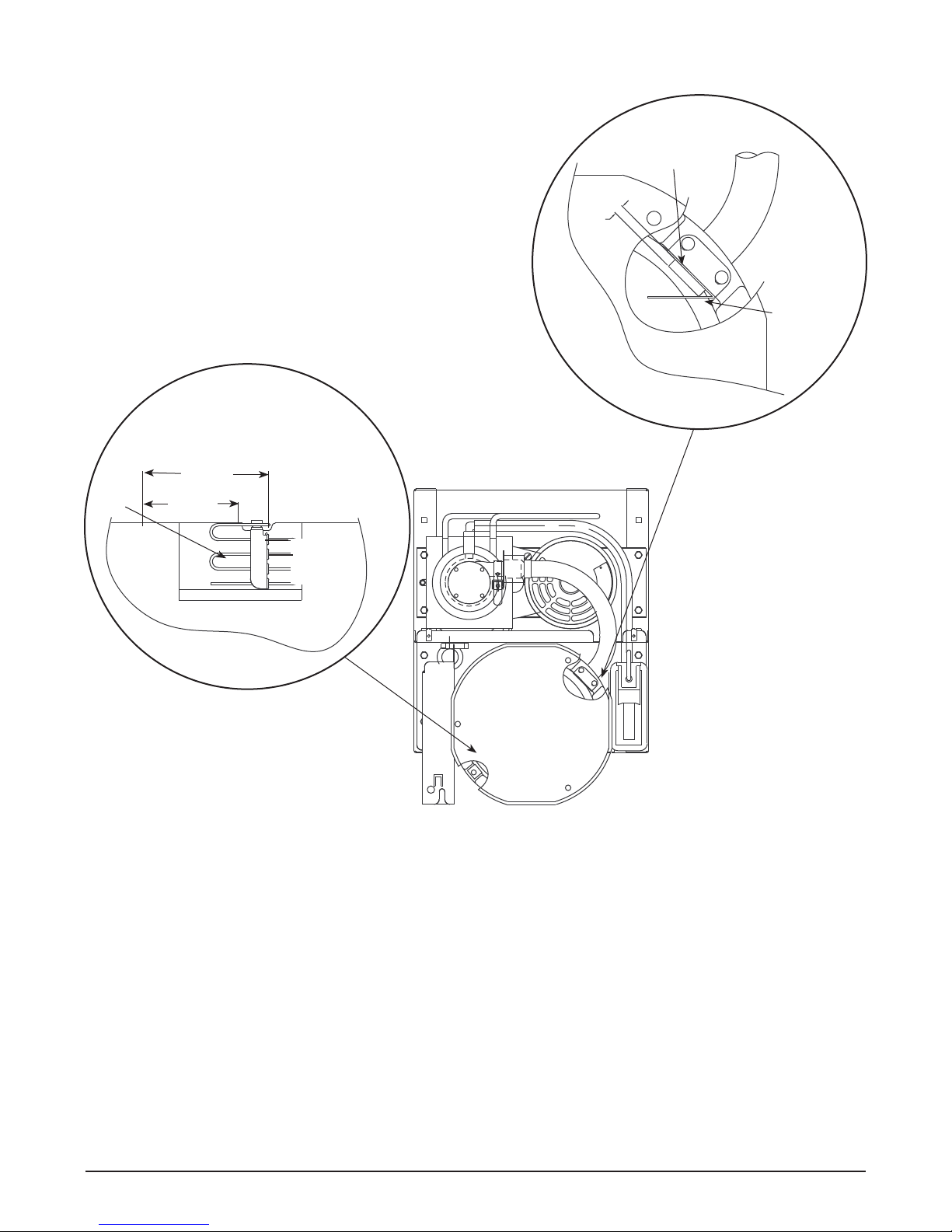
Thermostat and ice transport tube replacement
.25
ice tube retainer
ice tube
gasket
capillary
tube
bracket
77mm
(3")
51mm
(2")
13mm
(.50")
TYP
Thermostat:
hand bend cap tube end as shown
Top View
Ice transport
tube: tube may extend
a maximum of 7mm
(1/4") into ice bin
Ice transport tube replacement
1. Push tube onto evaporator port.
2. Position clamp behind lip on evaporator port and tighten clamp.
32 12CI400A • 12HI400A 220 V 60 Hz/230 V 50 Hz Dispensers
Page 33
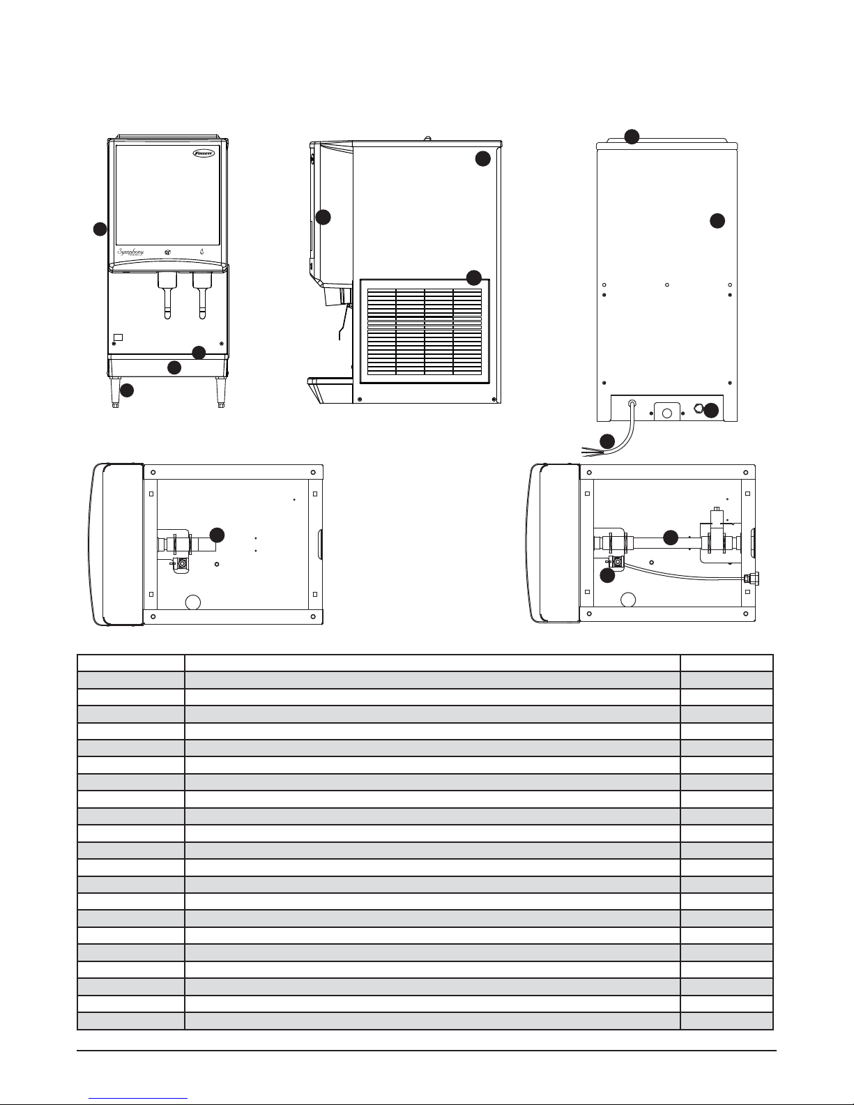
Replacement Parts
7
14
5
8
Dispenser exterior
9
10
3
4
6
1
11
1
2
12
13
Reference # Description Part #
1 Cover, front (serial numbers below D61292) 502818
1 Cover, front (serial numbers D61292 and above) 00981068
2 Louver, intake, plastic 00967117
Not shown Grille, drain pan 502412
3 Drain pan, plastic 00967059
4 Drain pan assembly (includes base, pan and grille) 502410
5 Panel, rear 502394
6 Leg kit, 4" (102 mm), adjustable – set of 4 502399
Not shown Fitting, water inlet, brass 502415
Not shown Fitting, water inlet, plastic 502924
7 Fitting, water inlet, brass 3/8" FPT 00137315
8 Lid, top panel, plastic (serial numbers below D61292) 502884
8 Lid, top panel, plastic (serial numbers D61292 and above) 00967091
9 Panel, right side 502396
10 Panel, left side 502395
11 Drain tube assembly, wall mount w/drain pan 502422
12 Drain tube assembly, countertop 502391
13 Elbow, water, 3/8" (10 mm) 502925
Not shown Drain tube assembly, wall mount w/o drain pan 502514
Not shown Bracket, wall 16" (406 mm) 502873
14 Cord, power 502940
12CI400A • 12HI400A 220 V 60 Hz/230 V 50 Hz Dispensers 33
Page 34
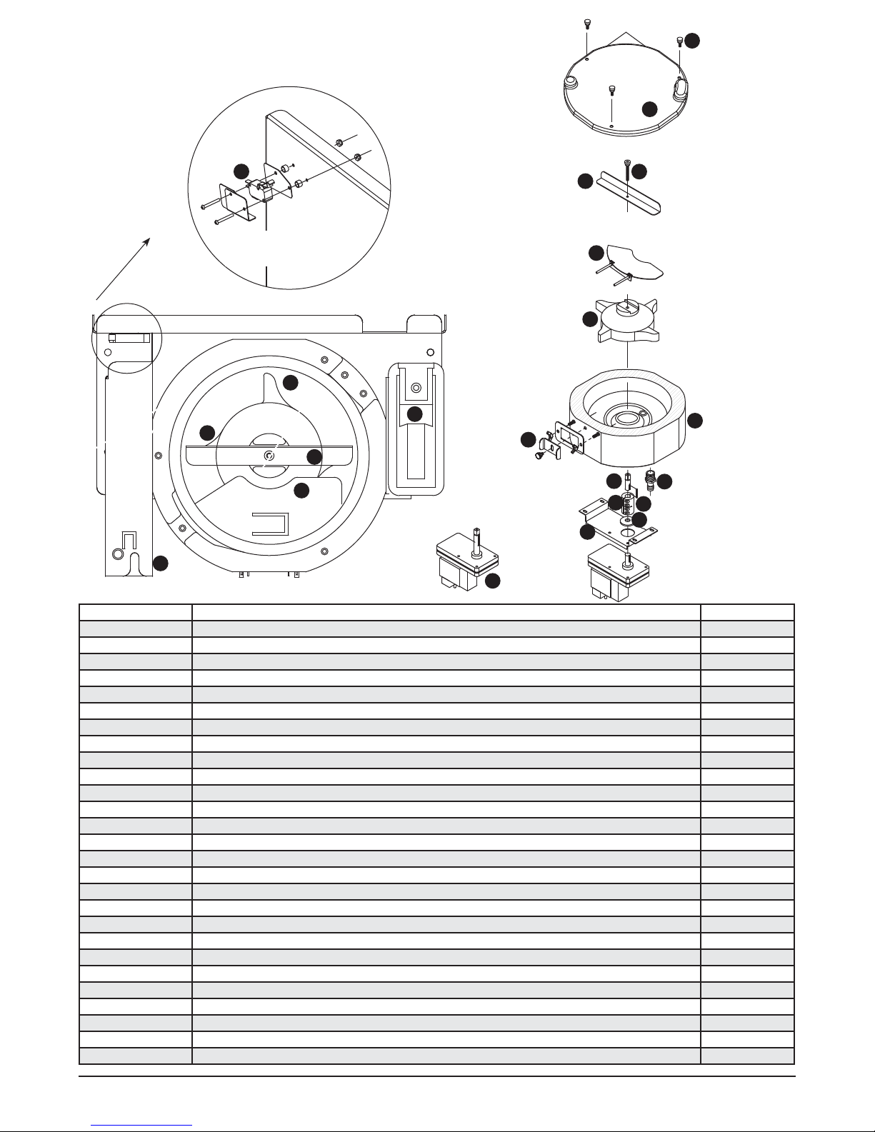
Wheelmotor and drive system
1
16
17
14
12
storage hopper
interlock switch
6
8
6
9
10
18
9
5
13
7
5
9
2
3
11
4
15
Top view
Reference # Description Part #
1 Motor, wheel, long shaft - 220 V 60Hz/230 V 50 Hz (includes gear motor shield) 502933
2 Drive shaft extension 502384
3 Coupling (includes key) (short shaft motor only) 502385
4 Key, 1/8" sq x 1-1/4 lg 501273
5 Baffle, ice (securing hardware, part# 00167973, included) 502414
6 Wheel with Agion, agitator 502387
7 Rod, threaded (includes knurled nut) 502390
8 Agitator, rotating 502386
See page 32 Bracket, capillary tube 502406
See page 32 Retainer, ice tube (2" high) 502404
See page 32 Retainer, ice tube (2.25" high) 00152017
See page 32 Retainer, ice tube 00977314
See page 32 Gasket, ice tube 502405
See page 32 Gasket, ice tube 00977322
9 Assembly, hopper with Agion (includes drain tting) 502413
10 Float valve and reservoir 500504
Not shown Bar, spacer 502389
Not shown Fitting, hopper drain (includes nut), 5/8" barb tting 502381
11 Fitting, hopper drain, 3/4 MPT, 3/4" barb tting 207095
12 Switch, interlock 502416
13 Support plate, motor 502423
14 Cover, electrical box 502408
15 Shield, gearmotor 502537
16 Screws, 10-32 x 1/2 (6 needed) 201022
17 Hopper lid with hopper lid safety switch actuation 00135962
Not shown Hopper lid, dispenser top cover, safety switch actuation (Before SN# B72959) 207809
18 Hardware, baffle securing 00167973
34 12CI400A • 12HI400A 220 V 60 Hz/230 V 50 Hz Dispensers
Page 35
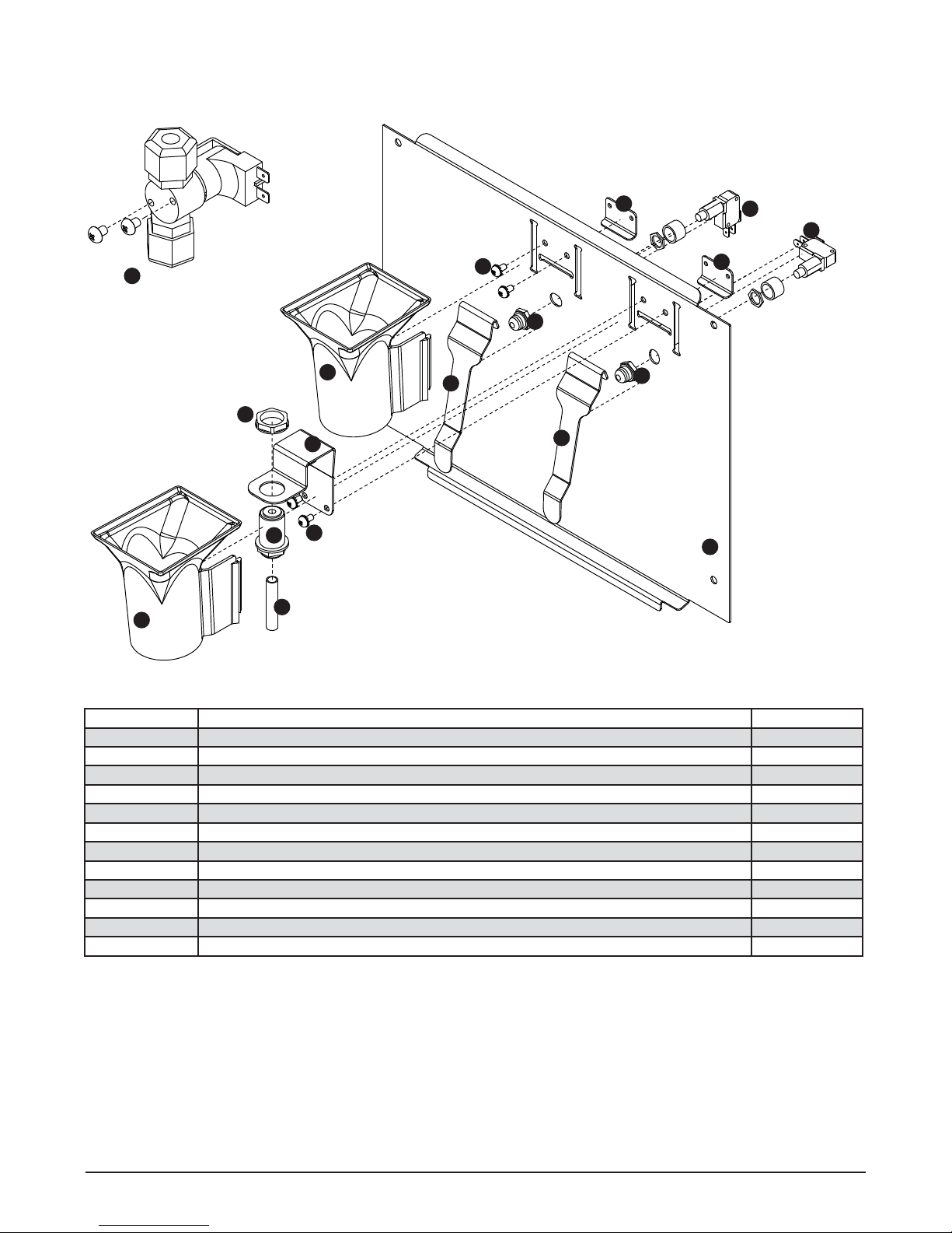
Dispense chute and splash panel (models with lever dispensing) —
Serial Number D61292 and above
11
(located behind
water reservoir)
1
7
5
4
1
9
2
5
9
8
3
3
4
6
6
7
10
Reference # Description Part #
1 Chute, ice or water (with Agion® antimicrobial product protection1) 00967760
2 Support, water tube 00960682
3Lever 00976845
4 Boot, dispense switch button 502418
5 Screw, panel 00982421
6 Switch, dispense 00981217
7 Bracket, lever support 00958793
8 Tube, water solenoid 502420
9 Fitting, bulkhead (with nut) 00976787
Not shown Splash panel (ice only) 00977850
10 Splash panel 00969980
11 Solenoid, assembly (includes ttings, screws) 01037746
1
Disclaimer: Antimicrobial protection is limited to the treated components and does not treat water or ice.
Agion is a registered trademark of Agion Technologies, Inc, Wake eld, MA, USA.
12CI400A • 12HI400A 220 V 60 Hz/230 V 50 Hz Dispensers 35
Page 36
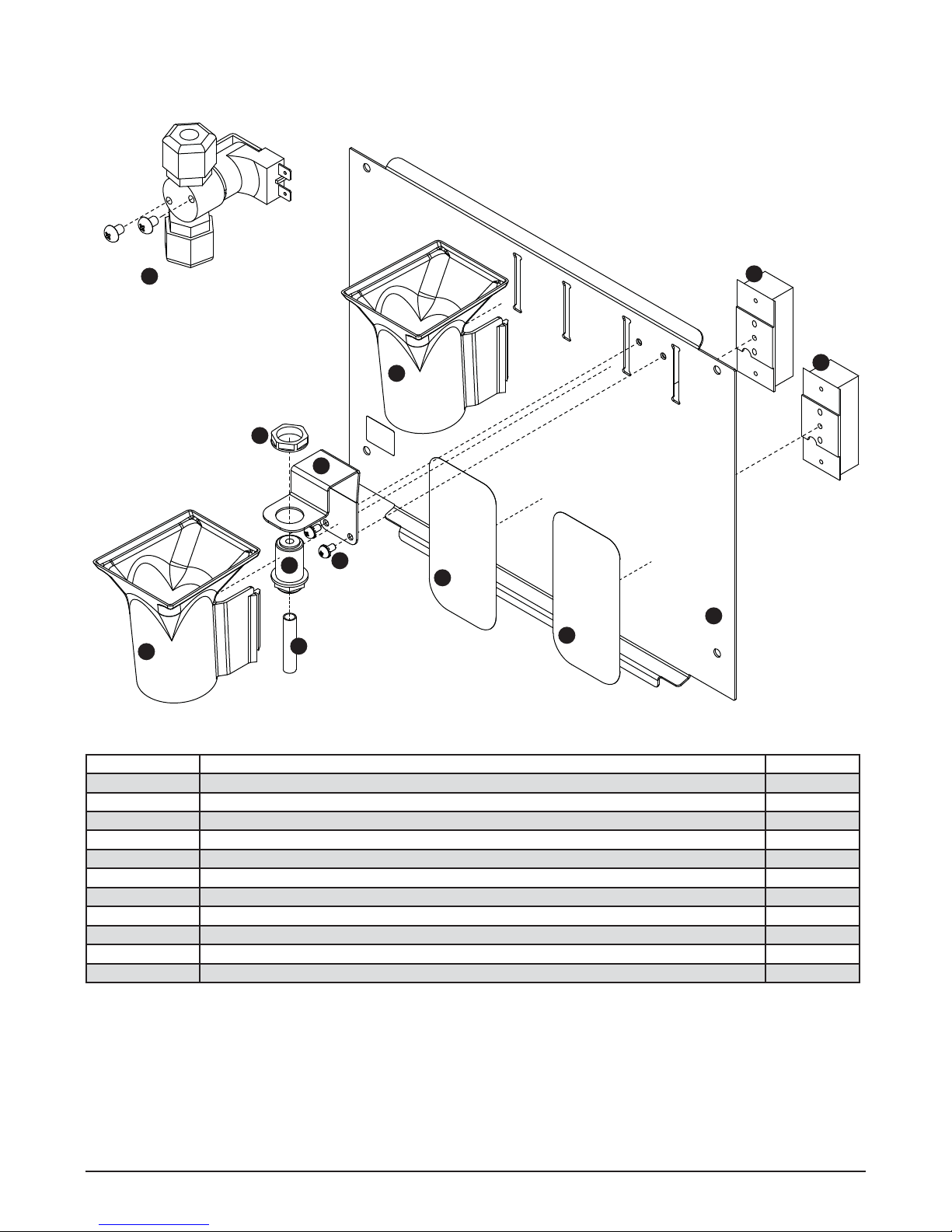
Dispense chute and splash panel (models with SensorSAFE infrared dispensing) —
Serial Number D61292 and above
9
(located behind
water reservoir)
1
2
1
5
3
5
4
8
7
6
8
2
Reference # Description Part #
1 Chute, ice or water (with Agion) 00967760
2 Sensor (includes lens and Ty-rap*) 00122978
3 Support, water tube 00960682
4 Screw, panel 00982421
5 Fitting, bulkhead (with nut) 00976787
6 Tube, water solenoid 502420
Not shown Splash panel, without drain pan (includes 2 Ty-raps and 2 lenses) 00981357
7 Splash panel, (includes 2 Ty-raps and 2 lenses) 00981332
8 Lens, sensor (each) 502690
Not shown Splash panel, ice only (includes 1 Ty-raps and 1 lens) 00981340
9 Solenoid, assembly (includes ttings, screws) 01037746
* Ty-rap is a registered trademark of Thomas & Betts International, Inc.
36 12CI400A • 12HI400A 220 V 60 Hz/230 V 50 Hz Dispensers
Page 37
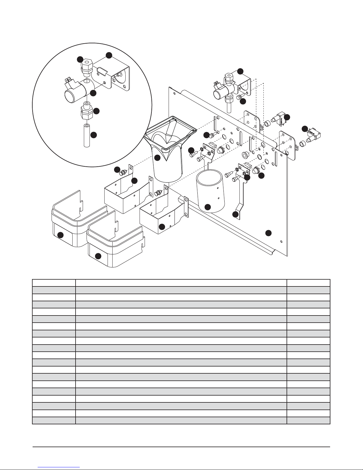
10
water solenoid assembly
12
13
11
14
Dispense chute and splash panel (models with lever dispensing) —
Serial Numbers below D61292
15
4
4
8
1
7
1
9
5
5
6
2
3
2
16
16
17
Reference # Description Part #
1 Chute, ice, with bracket and fasteners (with Agion) 00981225
1 Chute assembly (clear), ice 502513
2 Chute, water, with bracket and fasteners (with Agion) 00981233
2 Chute (clear), water 502249
3 Lever 502417
4 Thumbscrew 501100
5 Switch, dispense (includes nut, boot and spacer) 502409
6 Boot, dispense switch button (mounts over the dispense button) 502418
7 Fastener, dispense chute assembly 502057
8 Screws, dispense lever 501250
9 O ring 502427
10 Fitting, 1/4" tube 502561
11 Fitting, 3/8" tube 502562
12 Support bracket, solenoid 502419
13 Valve, solenoid water - 220 V 60 Hz/230 V 50 Hz 502926
14 Tube, water solenoid 502420
15 Solenoid, assembly (includes solenoid, ttings, tube & mounting bracket) 502926
16 Cover, dispense assembly 502819
17 Splash panel 00172767
12CI400A • 12HI400A 220 V 60 Hz/230 V 50 Hz Dispensers 37
Page 38
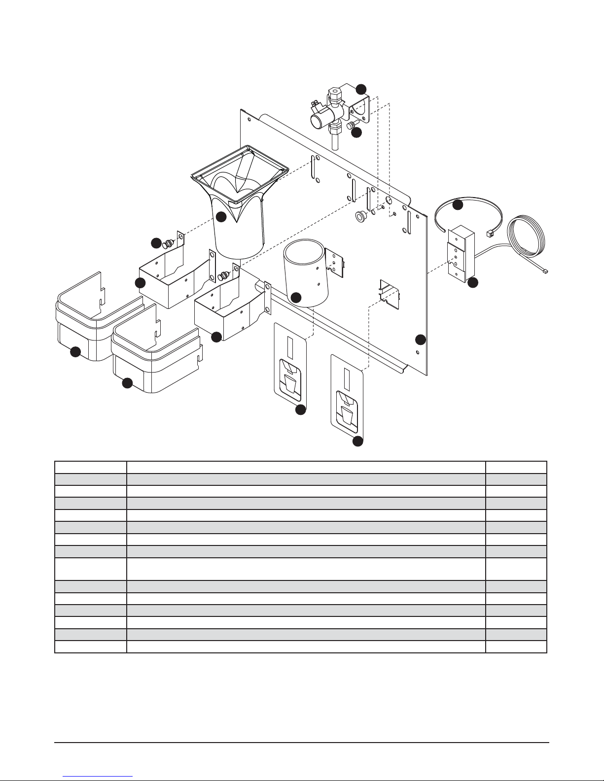
Dispense chute and splash panel (models with SensorSAFE infrared dispensing —
Serial Numbers below D61292
6
4
8
1
10
1
2
2
5
5
7
7
9
3
Reference # Description Part #
1 Chute, ice, with bracket and fasteners (with Agion) 00981225
1 Chute assembly (clear), ice 502513
2 Chute, water, with bracket and fasteners (with Agion) 00981233
2 Chute (clear), water 502249
3 Sensor (includes 502690 and 203611) 00122978
4 Thumbscrew 501100
5 Cover, dispense chute 502819
6 Solenoid assembly (includes solenoid, ttings, tube & mounting bracket, see
502421
page 37 for exploded view)
7 Lens, sensor (each) 502690
8 Ty-rap, sensor mounting 203611
9 Splash panel (with drain pan – includes (2) 203611 and (2) 502690) 502675
10 Fastener, dispense chute assembly 502057
Not shown Splash panel (without drain pan – includes (2) 503611 and (2) 502690) 502676
Not shown Splash panel (ice-only – includes (1) 503611 and (1) 502690) 00923581
38 12CI400A • 12HI400A 220 V 60 Hz/230 V 50 Hz Dispensers
Page 39
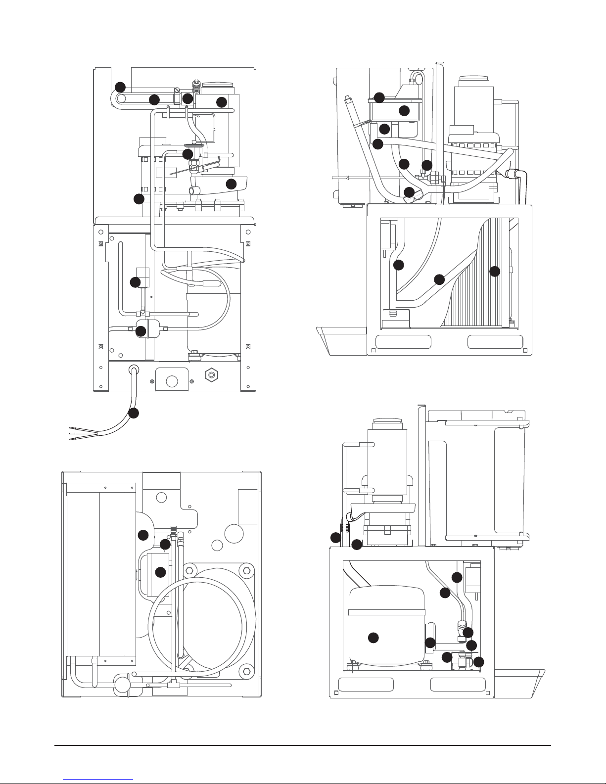
Ice machine components
20
21
5
8
6
3
4
19
28
17
26
23
10
24
1
Rear view
7
27
29
2
29
Right side view
12
14
13
OPERATE UNIT WITH
PANELS REMOVED.
12CI400A • 12HI400A 220 V 60 Hz/230 V 50 Hz Dispensers 39
CAUTION
.PANELS REMOVED
PARTS DO NOT
OPERATE UNIT WITH
HAZARDOUS MOVING
29
22
28
18
25
11
27
9
16
15
Left side viewTop view (lower section)
Page 40
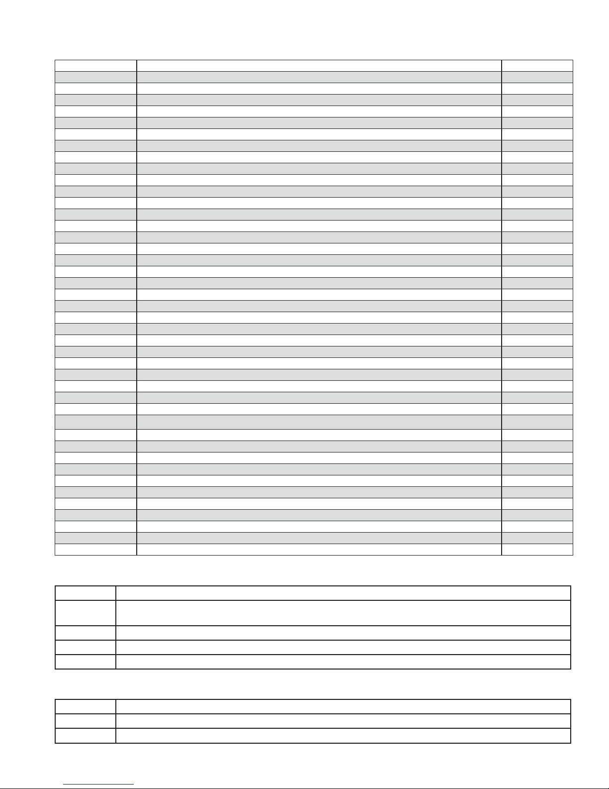
Ice machine components
Reference # Description Part #
1 Drier 502724
2 Coil, condenser 501187
3 Water sensor 502116
4 Float valve & reservoir 500504
Not shown Elbow, 1/4", push-in 00121699
Not shown Adapter, female thread to 1/4" push-in 00998716
Not shown Fitting, plastic, oat valve (includes sleeve & stem) 502078
5 Compression nozzle, single drain 502221
6 Evaporator (see page 42 for detailed drawing) —
Not shown Shroud, condenser coil 501820
7 Drain pan, evaporator 502727
8 Valve, expansion, thermal 502726
Not shown Valve, shut-off, water, brass 502222
9 Valve, shut-off, water, plastic 502921
10 Gearbox & motor, 220 V 60 Hz/230 V 50 Hz 502832
Not shown Strainer, water, threaded connections 500376
11 Strainer, water, push-in connections 502920
12 Fan blade 500474
13 Motor, fan, 220 V 60 Hz/230 V 50 Hz 00149765
14 Bracket, fan motor 501188
15 Overload, compressor, 220 V 60 Hz 502879
Overload, compressor, 230 V 50 Hz 502935
16 Compressor, 220 V, 60 Hz 502896
Compressor, 230 V 50 Hz 502834
17 Water line with Agion, evaporator 00135236
18 Tubing, polypropylene, reservoir supply (sold by the foot) 502079
19 Bracket, oat valve 502383
20 Tube, ice transport 00168112
21 Insulation, ice tube, 12" (305 mm) required 501176
22 Bracket, gearmotor mounting 502806
23 Cord, power 502940
24 Hi-pressure cut-out 502937
25 Clip, water shut-off valve 502922
Not shown Elbow, water, 3/8" 502925
26 Tee, water, 1/4" 502923
Not shown Gasket, ice hose 00977322
Not shown Relay, gear motor - 220 V 60 Hz/230 V 50 Hz 00120055
27 Pinch clamp 00988238
28 Drain tube with Agion, reservoir over ow 00980151
29 Drain tube with Agion, hopper/evaporator drain pan 00980144
Not shown Tubing, plastic, 5/8 ID, bin drain tube before SN# B72959 (sold by the foot) 500623
Not shown Adapter, 3/4" x 5/8" (Before SN# B72959) 00114199
Water lter kits and cartridges
Part# Description
00130229 Follett QC4-FL4S water lter system (includes FL4S primary cartridge and head, coarse pre- lter and head,
pressure gauge, ushing valve; assembled and installed on mounting bracket)
00130245 Follett FL4S primary replacement cartridge
00130211 Everpure coarse pre- lter cartridge
501781 Water pressure regulator (25 psi)
Ice machine cleaner
Part# Description
00132001 SafeCLEAN environmentally friendly ice machine cleaner, carton of 24 x 7 oz packets
00979674
40 12CI400A • 12HI400A 220 V 60 Hz/230 V 50 Hz Dispensers
Nu-Calgon IMS-II Sanitizer, 16 oz. bottle
Page 41
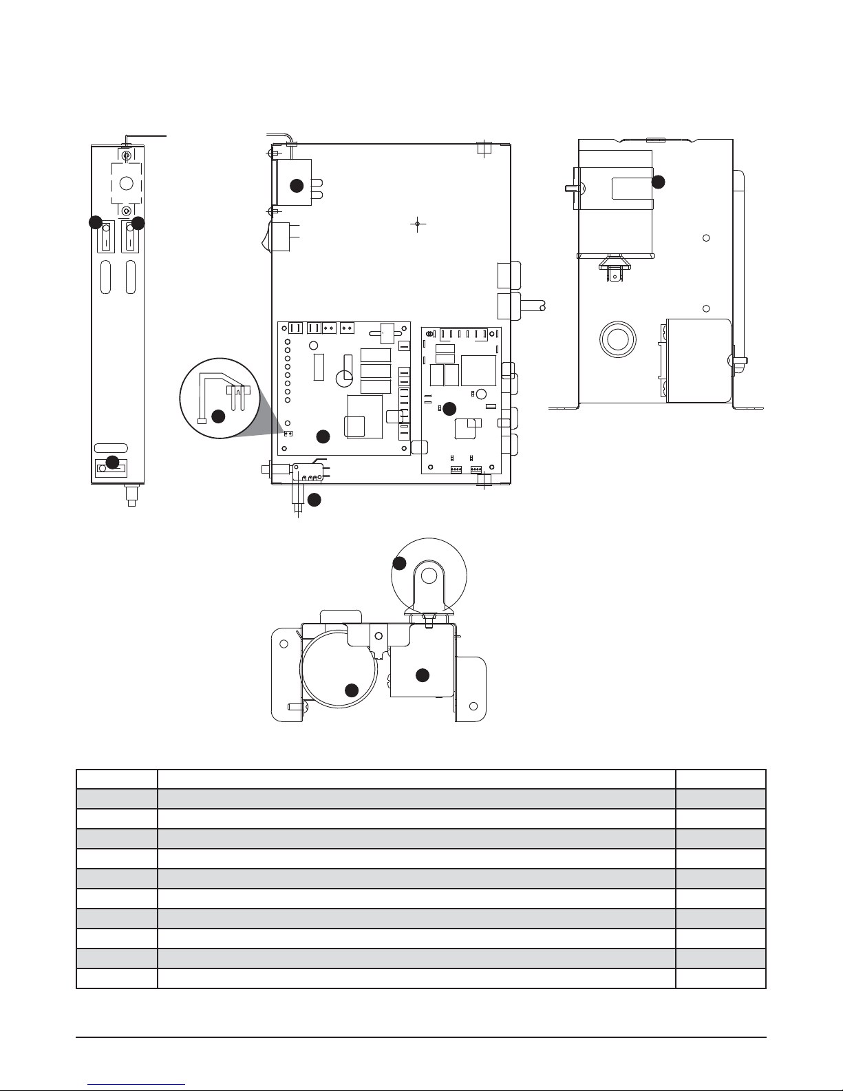
Electrical components
SIDE VIEW
4
4
4
TOP VIEW
5
WTR
SOL
WM
CLN
3
2
1
L1
NEUTRAL
PWR
Note: Located behind front splash
WTR
ICE
panel
FRONT VIEW
8
5
7
9
8
Reference # Description Part #
1 Board, control circuit – 220 V 60 Hz/230 V 50 Hz 502938
2 Control board, SensorSAFE
models – 220 V 60 Hz/230 V 50 Hz 502915
3 Water sensor 502116
4 Switch, on/off, compressor, bin signal 502209
5 Switch, cleaning, SensorSAFE models 502409
6 Bin thermostat 500514
7 Capacitor, start, compressor – 220 V 60 Hz/230 V 50 Hz 502835
8 Capacitor, run, compressor – 220 V 60 Hz/230 V 50 Hz 502837
9 Relay, start, compressor – 220 V 60 Hz 502899
9 Relay, start, compressor – 230 V 50 Hz 502836
12CI400A • 12HI400A 220 V 60 Hz/230 V 50 Hz Dispensers 41
Page 42
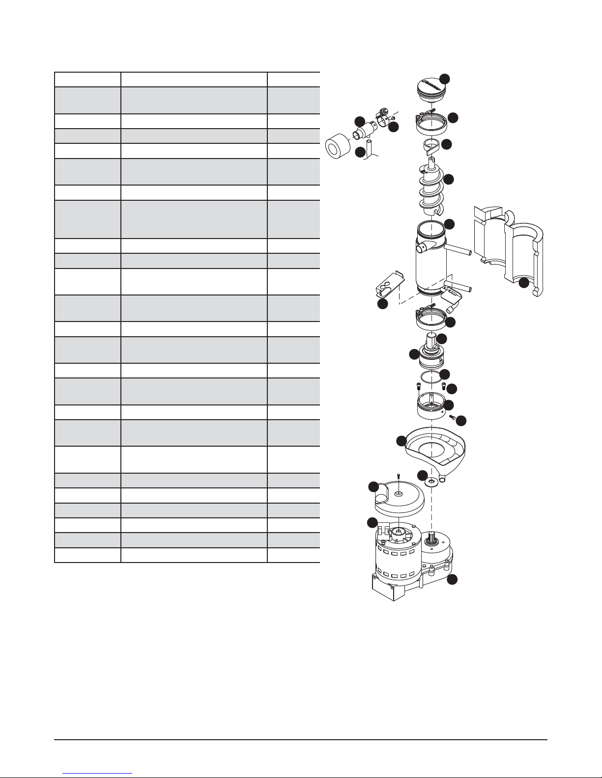
Evaporator replacement parts
Reference # Description Part #
1 Coupling, vee band, includes
502735
nut
2 Bearing assembly, top 502736
3 Loop, ice compression, beveled 502110
4 Auger 502737
5 Evaporator (includes insulation
502725
jacket, 502740)
6 O ring, bearing housing 500496
7 Bearing assembly, bottom
502738
(includes O rings and
condensate shield)
8 O ring, mounting base 501063
9 Shield, condensate 500744
10 Screw, Allen 1/4 20 x 1/2 (set
501080
of 4)
11 Mounting base, evap. (includes
502733
501063)
12 Bolt, mounting base 502227
13 Gearbox & motor assembly
00142034
(includes bracket)
Not shown Mounting base, gearbox 502729
15 Compression nozzle, with
502221
single drain
16 Drain pan, evaporator 502727
17 Clamp, compression nozzle
502226
and screw
18 Tubing, compression nozzle
500680
drain(s) (sold by foot)
Not shown Grease, Chevron SRI-2, 14oz 501111
19 Bracket, drain hose 502739
20 Insulation jacket, evaporator 502740
21 Relay, gearmotor 00120055
22 Cover, metal 502744
22 Cover, black plastic 01012228
15
18
2
1
17
3
4
5
20
19
1
7
6
8
10
11
12
16
9
22
21
42 12CI400A • 12HI400A 220 V 60 Hz/230 V 50 Hz Dispensers
13
Page 43

12CI400A • 12HI400A 220 V 60 Hz/230 V 50 Hz Dispensers 43
Page 44

SafeCLEAN, SensorSAFE and Symphony are trademarks of Follett Corporation.
Follett and RIDE are registered trademarks of Follett Corporation, registered in US.
801 Church Lane • Easton, PA 18040, USA
Toll free (877) 612-5086 • +1 (610) 252-7301
www.follettice.com
00124438R05
© Follett Corporation 3/13
 Loading...