

Page 1
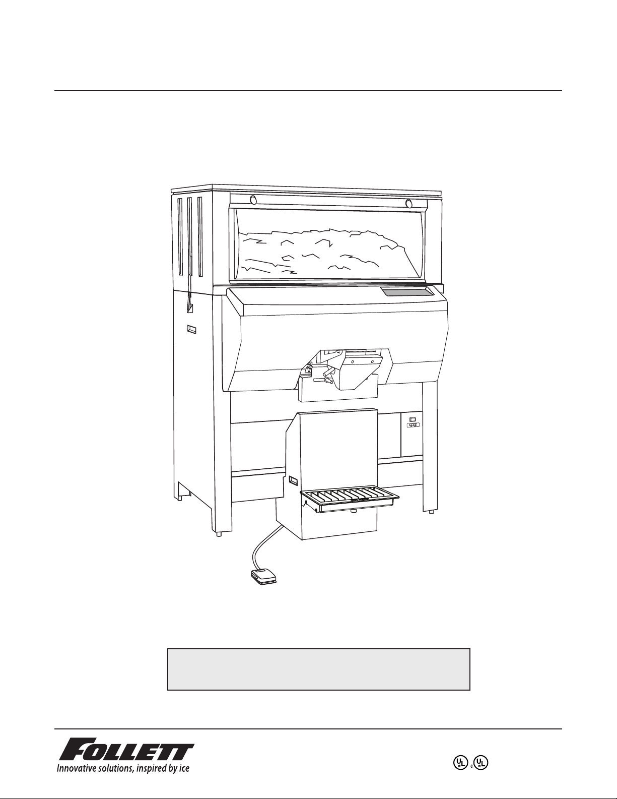
Ice Pro™ DB1000 Series Automatic
Ice Bagging and Dispensing System
Order parts online
www.follettice.com
Installation, Operation and Service Manual
Serial numbers above D51557
Following installation, please forward this manual
to the appropriate operations person.
801 Church Lane • Easton, PA 18040, USA
Toll free (877) 612-5086 • +1 (610) 252-7301
www.follettice.com
00109710R10
Page 2

Table of contents
Welcome to Follett Corporation
Important cautions
Specifications
Installation
Door entry
Locating unit
Leg extension accessory
Leveling
Utility connections
Foot pedal
Bag wicket
Sanitize
Icemaker
Adjustments
Cleaning and sanitizing
Exterior care
Interior care
Semi-annual cleaning
Operation
How the dispenser works
System overview
Control functions
Bag pins – installing wickets
Adjusting bag stand height
™
Using Totes
Using SmartCART
Removing bag stand
Service
Agitator removal
Wiring diagram
Troubleshooting guide
Replacement parts
or other containers
™
or other mobile ice storage devices
3
3
4
6
6
9
9
9
9
9
10
10
10
10
11
11
11
11
12
12
12
13
14
14
14
14
14
15
15
16
17
18
2
Page 3
Welcome to Follett
Follett ice dispensers enjoy a well-deserved reputation for excellent performance, long-term reliability and
outstanding after-the-sale support. To ensure that this dispenser delivers that same degree of service, we ask
that you take a moment to review this manual before beginning the installation of the dispenser. Should you have
any questions or require technical help at any point, please call our technical service group, (877) 612-5086 or
+1 (610) 252-7301.
Before you begin
After uncrating and removing all packing material, inspect the equipment for concealed shipping damage. If
damage is found, notify the shipper immediately and contact Follett Corporation so that we can help in the filing of
a claim, if necessary.
Check your paperwork to determine which model you have. Follett model numbers are designed to provide
information about the type and capacity of Follett ice dispensing equipment. Following is an explanation of the
different model numbers in the DB1000 series.
DB1000SA
SA = Semi-Automatic ice dispensing and bagging
1000 – 1000 lbs maximum bin capacity
DB – Dispensing bin - 220/60 Hz
EDB – Dispensing bin - 230/50 Hz
Important cautions
!
Storage area of dispenser contains mechanical, moving parts. Keep hands and arms clear of
this area at all times. If access to this area is required, power to unit must be disconnected first.
Ice is slippery. Maintain counters and floors around dispenser in a clean and ice-free condition.
Ice is food. Follow recommended cleaning instructions to maintain cleanliness of delivered ice.
Should local codes require a hard-wired connection and/or shielded wiring, eliminate the cord(s)
and plug(s) and follow the appropriate wiring diagram.
Dispenser can accommodate most cube/cubelet ices up to 1" square. Crushed, flake, or nugget
ice cannot be used. Use of these ices can jam dispenser and void warranty. For questions about
ice compatibility, call Follett’s customer service group toll free at (877) 612-5086 or +1 (610) 252-7301.
Always disconnect power before cleaning or servicing the dispenser.
Failure to remove all sanitizer may result in health hazard.
3
Page 4

Specifications
Electrical
Each icemaker and dispenser requires separate circuit. Equipment ground required.
Standard electrical - 220V, 60Hz, 1 phase, Max. fuse – 5 amps, 15 amp circuit. Cord and plug provided.
Plumbing
Drain 1" PVC FPT for hopper drain
Note: Drains should be hard piped and insulated. Maintain at least 1/4" per foot (1cm per 31cm run) slope
on drain line run
Clearance and access information
Door entry Installation sites must have an unobstructed path to installation location
with door openings no less than 34.25" (870mm)
Service Clearance A minimum of 12" (305mm) to left of unit is necessary for service
Ice type
Dispenser can accommodate most cube/cubelet ices up to 1" square. Crushed, flake, or nugget ice cannot be
used. Use of these ices can jam dispenser and void warranty. For questions about ice compatibility, call Follett’s
technical service group toll free at (877) 612-5086 or +1 (610) 252-7301.
Icemaker weight limit
Icemaker(s) mounted on thin top may not exceed 800 lbs (364kg)
Icemaker(s) mounted on thick top may not exceed 1300 lbs (590kg)
Container sizes
Standard unit accommodates bag sizes up to 20 lbs (9kg) / 27.35" (696mm)
Standard dispense chute compatible with carts and containers up to 29.5" (750mm) high
Optional 6.5" (166mm) leg extension kit may be purchased to allow for up to 36" (915mm) high carts
and bags up to 40 lbs (18kg) and 33.85" (860mm) high
Bag pins
Bag pins may be adjusted to accommodate bag hole centers from 5" (127mm) to 10" (254mm)
4
Page 5
Dimensions and clearances
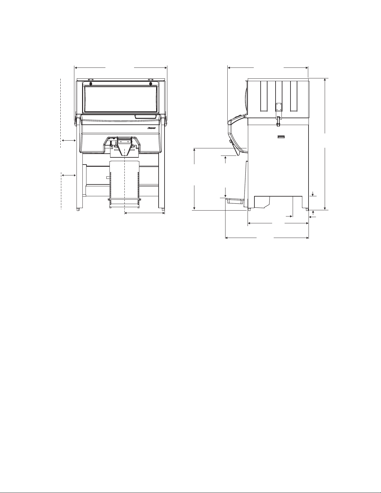
12" (305mm)
Service
Clearance
Front view
52.0"
(1321mm)
22.5" (572mm)
1" FPT drain
31"
(788mm)
max. cart
27.35"
(695mm)
max. bag
Side view
45.5"
(1156mm)
(864mm)
46.75"
(1188mm)
34"
71.75"
(1823mm)
7"
(18mm)
9.5"
(242mm)
1" FPT
drain
Notes
Special top required for icemakers weighing more than 800 lbs (364kg). Adds an additional 2.125" (54mm) to
height. Contact factory.
Add 2" (51mm) to depth and 10 lbs (4.5kg) to shipping weight when drain pan accessory used.
5
Page 6
Installation
1
1
2
3 – PCB POWER J22
AGITATION MOTOR J23
4 – AUGER MOTOR J24
2 – CONTROL J21
1 – WINDOW INTERLOCK J26
FOOTSWITCH J27
Door Entry
Some disassembly may be necessary to gain access through door
openings with a width of 34.25" (850mm) to 45.5" (1156mm).
Note: Disassembly is NOT necessary for gaining entry through
door openings larger than 45.5" (1156mm)
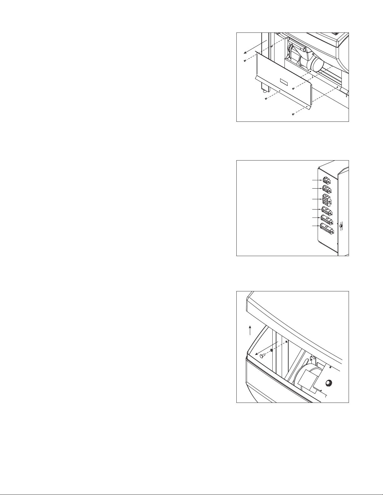
1. Remove lower splash panel with four screws (Fig. 1.1).
Fig. 1
2. Detach the following plugs from the left side of control box:
a) Window interlock J26 (Fig. 2.1)
b) Control J21 (Fig. 2.2)
c) PCB power J22 (Fig. 2.3)
d) Auger motor J24 (Fig. 2.4)
(model DB1000SA only)
3. Remove control panel cover by lifting and detaching hook and
loop tape (Fig. 3.1).
4. Remove lower cover with two thumbscrews, one from each
side (Fig. 3.2).
Fig. 2
Fig. 3
6
Page 7
1
2
3
4
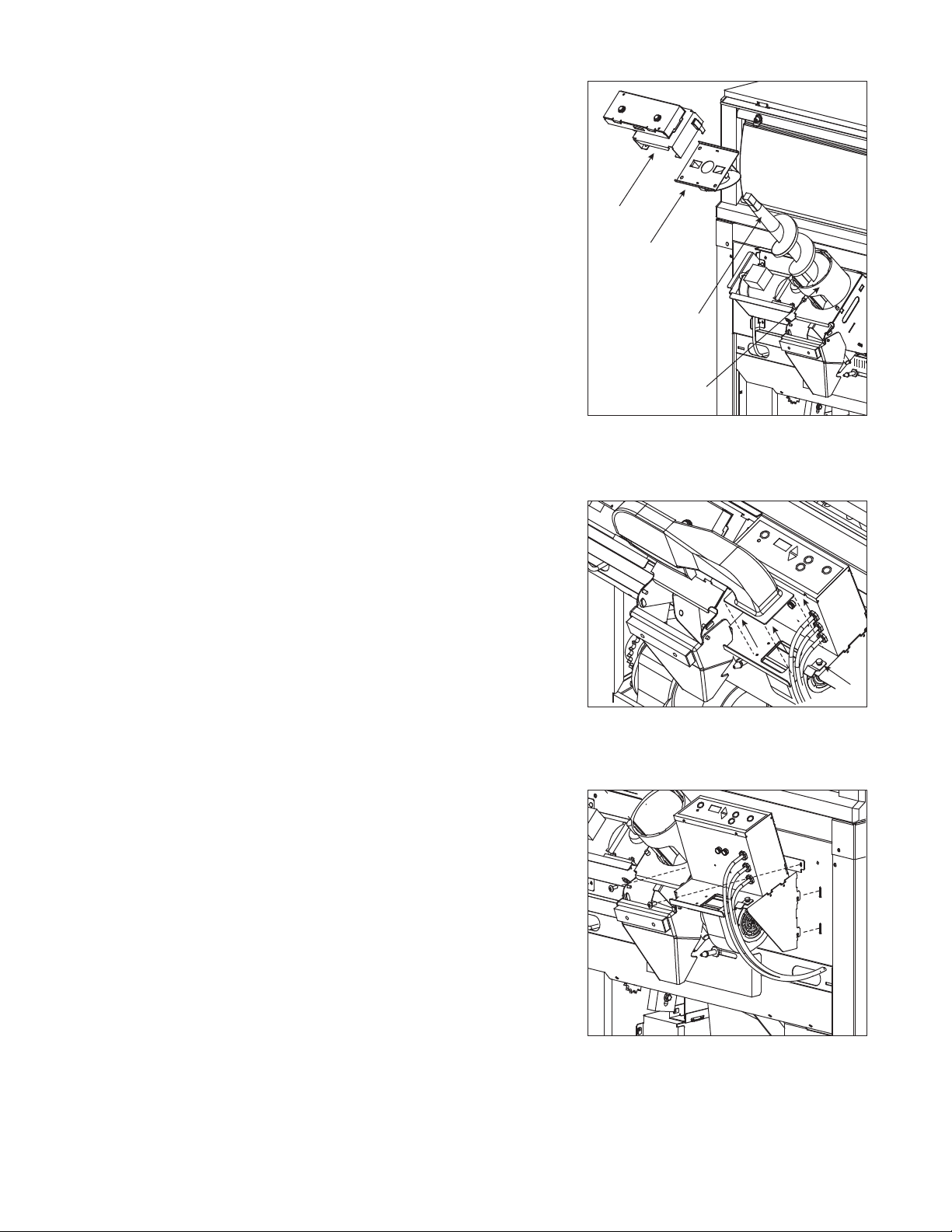
6. Remove ice deflection plate by lifting up (Fig. 4.2).
1
2
7. Remove auger by lifting up (Fig. 4.3).
8. Remove auger tube by lifting up. Note position of locating slot
on lower end for reinstallation (Fig. 4.4).
Fig. 45. Remove transfer case with two latches (Fig. 4.1).
9. Remove blower duct by loosening thumb screw, rotating clip
(Fig. 5.1) and lifting up (Fig. 5.2).
10. Remove control box/fan motor mounting assembly with two
screws (Fig. 6).
Fig. 5
Fig. 6
7
Page 8
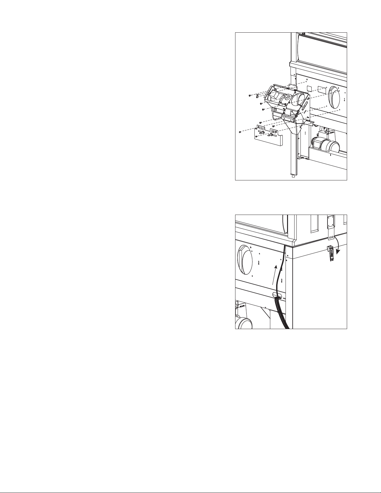
11. Remove auger motor bracket with 8 screws (Fig 7).
1
2
12. Remove bag pin bracket with two thumbscrews (Fig. 7).
Fig. 7
13. The unit's width may be further reduced by removing the upper
ice storage section (Fig. 8). This reduces unit width by
1.75" (45mm) to an overall width of 34" (864mm).
a) Remove window.
b) Pull window interlock switch cable through wire trough in
upper right corner of base (Fig. 8.1).
c) Cut tie wrap.
d) Release latch from each side of ice storage section
(Fig. 8.2).
e) Lift upper ice storage section from base.
Note: Reinstallation of auger tube requires locating slot be in the
7 o’clock position and upper end of auger be flush to auger
motor bracket.
Fig. 8
8
Page 9
Locating unit
A minimum of 12" (305mm) to the left of the unit must be unobstructed
for service clearance (see dimensions and clearances).
Fig. 9
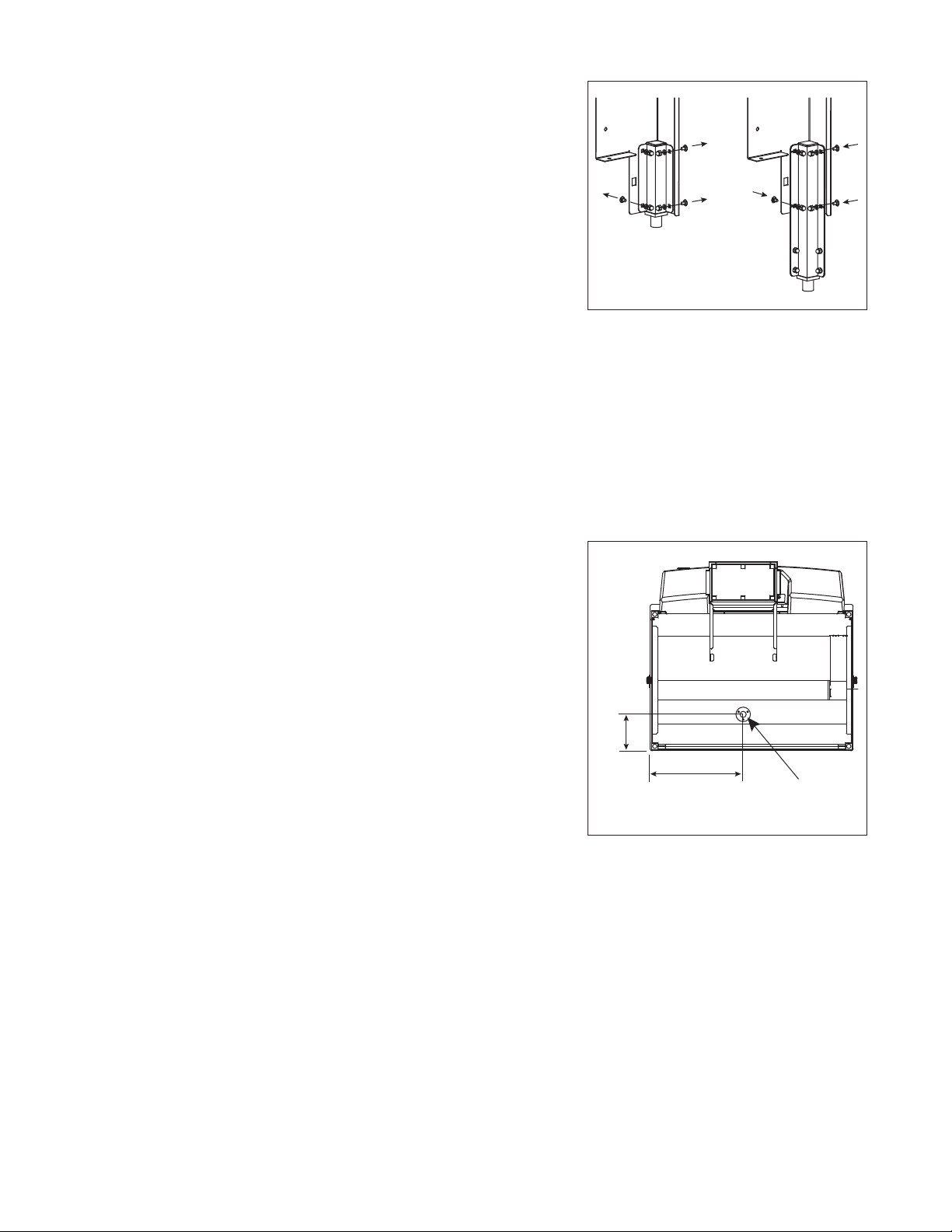
Leg extension accessory
1. Raise unit off feet.
2. Remove each standard foot channel with four carriage bolts
(Fig. 9.1).
3. Remove foot insert and cap insert from standard foot channel.
4. Align each accessory extension foot channel to the eight
holes of leg.
4. Use the four carriage bolts removed in step 2 and four carriage
bolts supplied with leg extension accessory to attach each
extension channel to the eight holes of each leg (Fig. 9.2).
6. Place foot insert and cap insert into extension foot channel.
5. Verify each leg is in fully retracted position prior to lowering
unit on feet.
6. Follow leveling instructions below.
Leveling
Leveling the unit is important for the proper operation of any
top mounted icemaker. The dispenser is shipped with the legs in the
fully retracted position. Each leg may be adjusted independently by
turning clockwise to lower the leg or counterclockwise to raise the leg.
1
Fig. 10
1
1
2
2
2
Utility connections
Drain
Drain connection is made to the 1" FPT PVC fitting (Fig. 10). Leave
a minimum of 1/4" per foot (1cm per 31cm run) slope on drain line
run. Insulate the entire run length to prevent condensation from
forming on outside of drain line.
Note: Avoid excessive tightening force when connecting
to this fitting.
Note: Do not apply excessive heat if any sweating of fittings is
necessary. Heat conduction through metal may melt
threads in plastic drain.
Electrical
Make electrical connections in accordance with local and NEC
codes. Each icemaker and dispenser requires separate circuit.
Equipment ground required.
Standard electrical – 220V, 60Hz, 1 phase. Max. fuse – 5 amps,
15 amp circuit. Cord and plug provided.
Foot pedal
The foot pedal is installed to the dispenser at the factory. Remove
packaging and place on floor near bag stand on front of dispenser.
8.875"
(226mm)
22.875"
(582mm)
drain
9
Page 10
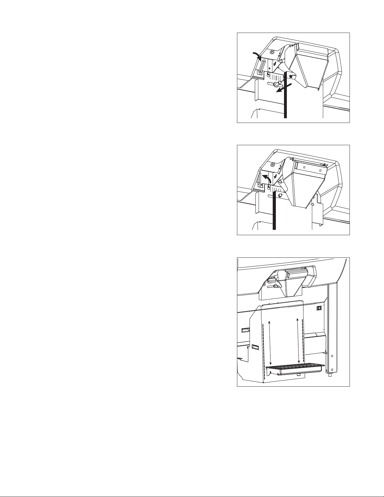
Bag wicket
1
2
Note: Bags must be placed behind rear stainless chute.
1. Move chute lever to down position (Fig. 11.1).
2. Transfer bags from wicket to bag pins by removing cardboard
backing and sliding 15 to 20 bags onto pins at a time until
posts are full (Fig. 11.2).
3. Return chute lever to up position (Fig. 12).
Sanitize
Follow cleaning and sanitizing instructions.
Fig. 11
Icemaker
Follow icemaker manufacturer’s recommendations for installation.
Note: Icemaker(s) mounted on thin top may not exceed 800 lbs
(364kg). Icemaker(s) mounted on thick top may not exceed
1300 lbs (590kg).
Adjustments
The installer should make the following initial adjustments to ensure
proper operation of the dispenser.
Bagger starter kit (DB1000SA models only)
The Ice Pro model DB100SA includes 250 bags.
1. Begin using the bags by locating the bagger starter kit and
following the the instructions for bag wicket on page 10.
2. Follett recommends ordering new replacement bags
immediately and confirming delivery date.
Bag stand
The bag stand platform may be raised or lowered to accommodate
multiple bag sizes (Fig. 13). The bottom of bags should touch
platform when adjustment is complete.
1. Lift bag stand platform up and out of receiving slot on bag
stand base.
2. Insert bag stand platform in and down into next receiving slot
above bottom of bag.
Fig. 12
Fig. 13
Dispense duration (model DB1000SA only)
In timed mode, the dispense duration dial of the control panel
adjusts the length of time the unit dispenses ice.
1. Rotate dial clockwise to lengthen dispense duration. Rotate counterclockwise to shorten dispense
duration.
2. Verify timed mode is selected.
3. Press start button to test length of duration. Adjust as necessary.
10
Page 11
1
2
1
5
6
7
2
4
3
Review operation procedures with appropriate operations person.
Give manual to appropriate operations person.
Cleaning and sanitizing
Solution A – Cleaning solution:
Combine 1 oz (30ml) bleach with 2 gal (8L) hot water or use an
equivalent sanitizer and mix for 200 ppm.
Solution B – Sanitizing solution:
Combine 1/4 oz (7ml) bleach with 2 gal (8L) hot water or use an
equivalent sanitizer and mix for 50 ppm.
Cleaning brush
A cleaning brush is included with the Ice Pro – it should be mounted for
easy access on either side of the bin in the bracket provided.
Exterior care
The stainless steel exterior of the bin can be cleaned with a stainless
cleaner such as 3M Stainless Steel Cleaner & Polish or equivalent.
Interior care
The polyethylene liner should be cleaned and sanitized periodically with
cleaning solution prescribed below.
Fig. 14
Fig. 15
Recommended semi-annual cleaning
(every 6 months)
1. Disconnect power from ice machine and dispenser.
2. Remove all ice from storage area.
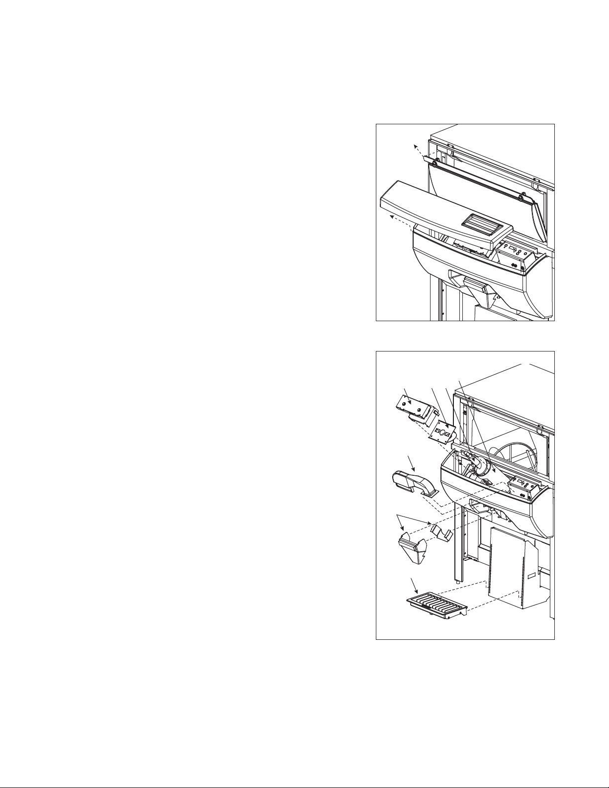
3. Remove ice storage window (Fig. 14.1).
4. Remove control panel cover by lifting and detaching latch
and loop tape (Fig. 14.2).
5. Remove transfer case with two latches (Fig. 15.1).
6. Remove ice deflection plate by lifting up (Fig. 15.2).
7. Remove auger by lifting up (Fig. 15.3).
8. Remove auger tube by lifting up. Note position of locating slot on
lower end for reinstallation (Fig. 15.4).
9. Remove blower duct by loosening thumb screw, rotating clip
and lifting up (Fig. 15.5).
10. Remove ice chute assembly (Fig. 15.6).
11. Remove drain pan from bag stand (Fig. 15.7).
12. Clean all components and bin storage surfaces with supplied brush and Solution A.
Rinse thoroughly with clean water. Sanitize all components and bin storage surfaces
with Solution B.
13. Pour a solution of one cup (8oz/237ml) household bleach mixed with one gallon (3.8L)
hot water into drain to help prevent algae growth in drain lines.
11
Page 12
Operation
AA
AA
BB
B
B
AA
BB
How the dispenser works
Follett’s Ice Pro bagging and dispensing system is available in manual or semi-automatic ice dispensing and
bagging configurations. The semi-automatic model includes a blower to puff bags open for high volume, handsfree dispensing, bag holder pins for use with wicketed bags and programmable dispense timer.
Ice is stored above a dispense auger in the dispenser storage area. An automatic agitation cycle keeps the ice
from congealing by periodically activating the agitator. When the start button is pressed, the dispense motor is
activated. This causes the auger assembly in the storage area to move ice to the dispense chute where it drops
by gravity into a container.
System overview
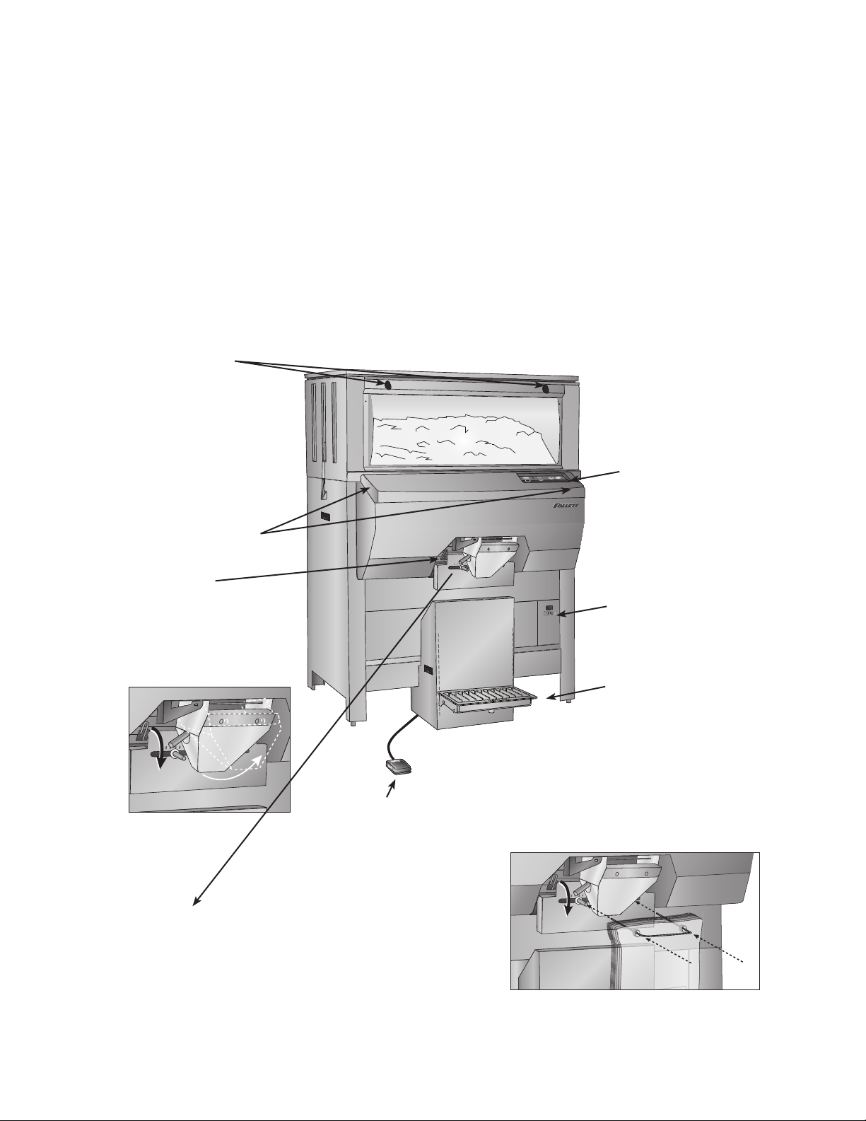
Window locks
Prevents
unintended
access to ice
storage area
Window
interlock switches
Shuts unit off when
window is removed
Chute lever
Positions chute lever in
up position (A) when
bagging or down
position (B) to load
containers or carts
Control panel
See detailed
description on
next page
Power switch
System ON/OFF
Stand assembly
(DB1000SA only)
Drain pan may be removed to
empty water or to adjust bag
height. Stand should support
bottom of bag. Stand support
may be removed for cart filling.
Foot pedal
Starts dispensing in
manual mode. Use for
topping off bags and
containers in timed mode.
Bag pins (DB1000SA only)
Bags must be placed behind rear stainless chute. Move
chute lever to down position (B). Transfer bags from wicket
to bag pins by removing cardboard backing and sliding
bags onto pins. Return chute lever to up position (A).
12
Page 13
Control functions
Ice Pro
™
dispensing bin
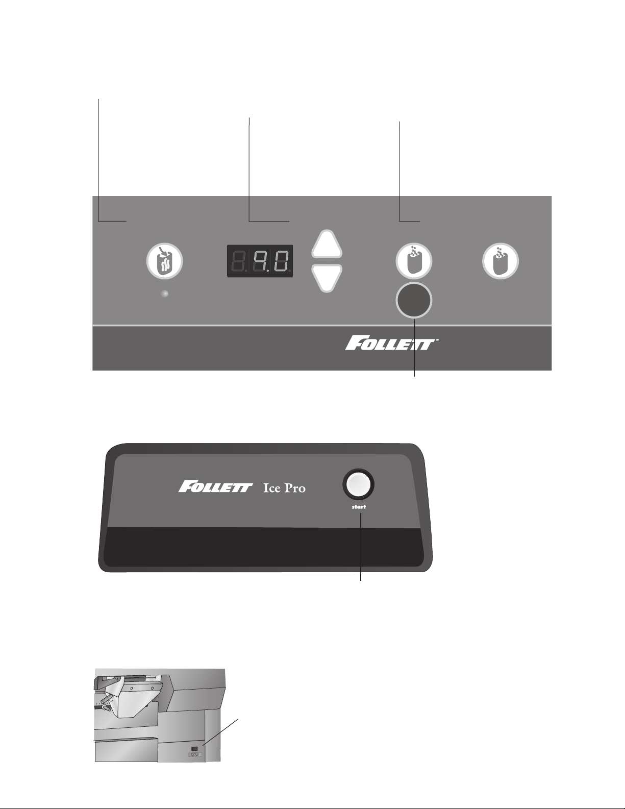
1. Open bag 3. Dispense ice2. Adjust time
+
-
ManualTimed
STOP
Model DB1000SA – Semi-automatic ice bagging and dispensing system controls
1. Open bag
Press to turn on blower.
Automatically blows
open one bag at a time
Press again to turn
blower off. Blower
automatically turns
off after 10 minutes.
2. Adjust time
Press +/– to change
timed dispense duration
in seconds - maximum
time: 30 seconds
3. Dispense ice
Press Timed once to
dispense automatically.
Hold Manual to top off
bag or ll other containers
Model DB1000 – manual ice dispensing system controls
Power switch
Note: Do not turn power OFF during normal operation. Turning power OFF disables agitation cycle
which may lead to congealed ice and damage to dispenser that may void warranty.
DO NOT
TURN POWER
OFF DURING
NORMAL
OPERATION
Stop
Press to stop timed dispense
Start
Hold down to dispense
13
Page 14
Bag pin – installing wickets (Model DB1000SA only)
1
2
1
2
Note: Bags must be placed behind rear stainless chute.
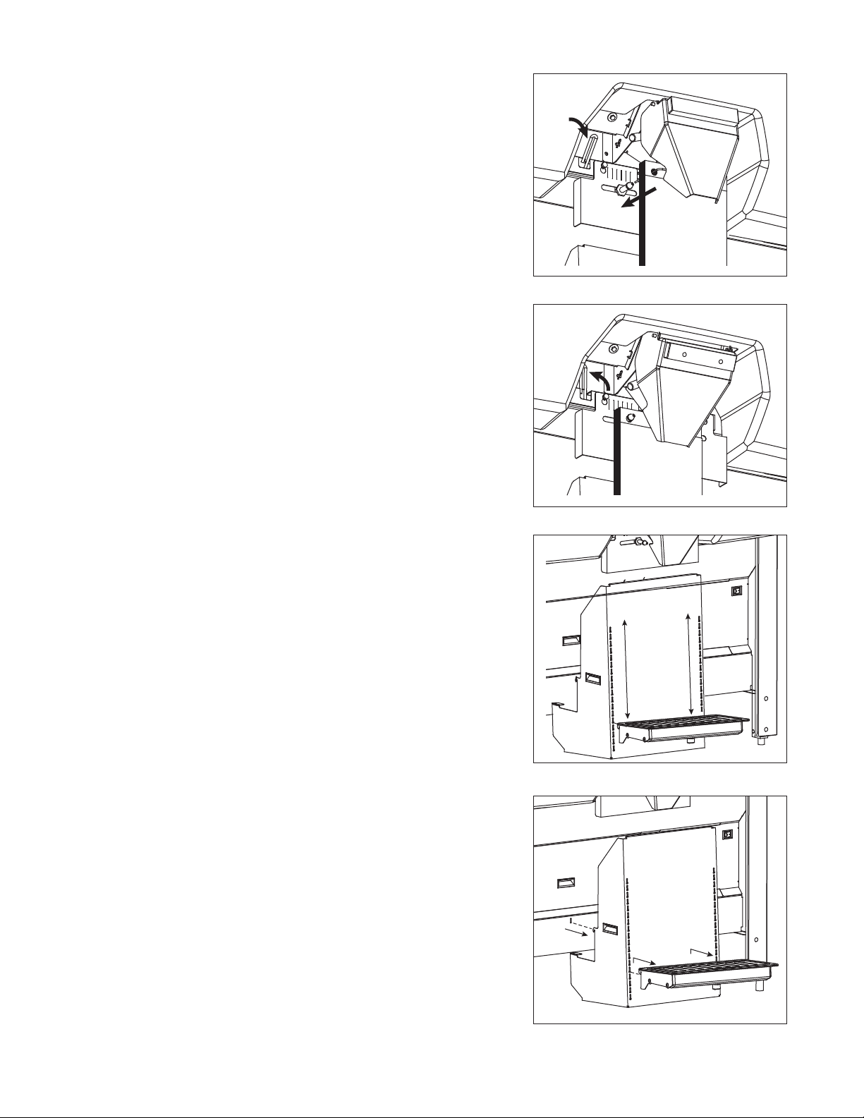
1. Move chute lever to down position (Fig. 16.1).
2. Transfer bags from wicket to bag pins by removing cardboard
backing and sliding 15 to 20 bags onto pins at a time until
posts are full (Fig. 16.2).
3. Return chute lever to up position (Fig. 17).
Adjusting bag stand height (Model DB1000SA only)
The bag stand platform may be raised or lowered to accommodate
multiple bag sizes (Fig. 18). The bottom of bags should touch
platform when adjustment is complete.
1. Lift bag stand platform up and out of receiving slot on bag
stand base.
2. Insert bag stand platform in and down into desired receiving
slot on bag stand base.
Fig. 16
Fig. 17
Using Totes
The bag stand platform can accommodate containers of up to
29.5" (750mm) high.
1. Adjust bag stand height per instructions above.
2. Position chute lever in down position (Fig. 16.1).
3. Place container below dispense chute.
4. Press START.
Using SmartCART
™
or other containers
™
or other mobile ice storage
devices
The bag stand platform must be removed to correctly position
SmartCART under chute.
1. Remove bag stand per instructions below.
2. Position chute lever in down position.
3. Roll SmartCART under dispense chute.
4. Press START.
Removing bag stand (Model DB1000SA only)
1. Lift bag stand platform up and out of receiving slots on bag
stand base (Fig. 19.1).
2. Lift stand up and out of receiving slots on dispenser base
(Fig. 19.2).
Fig. 18
Fig. 19
14
Page 15
Service
2
1
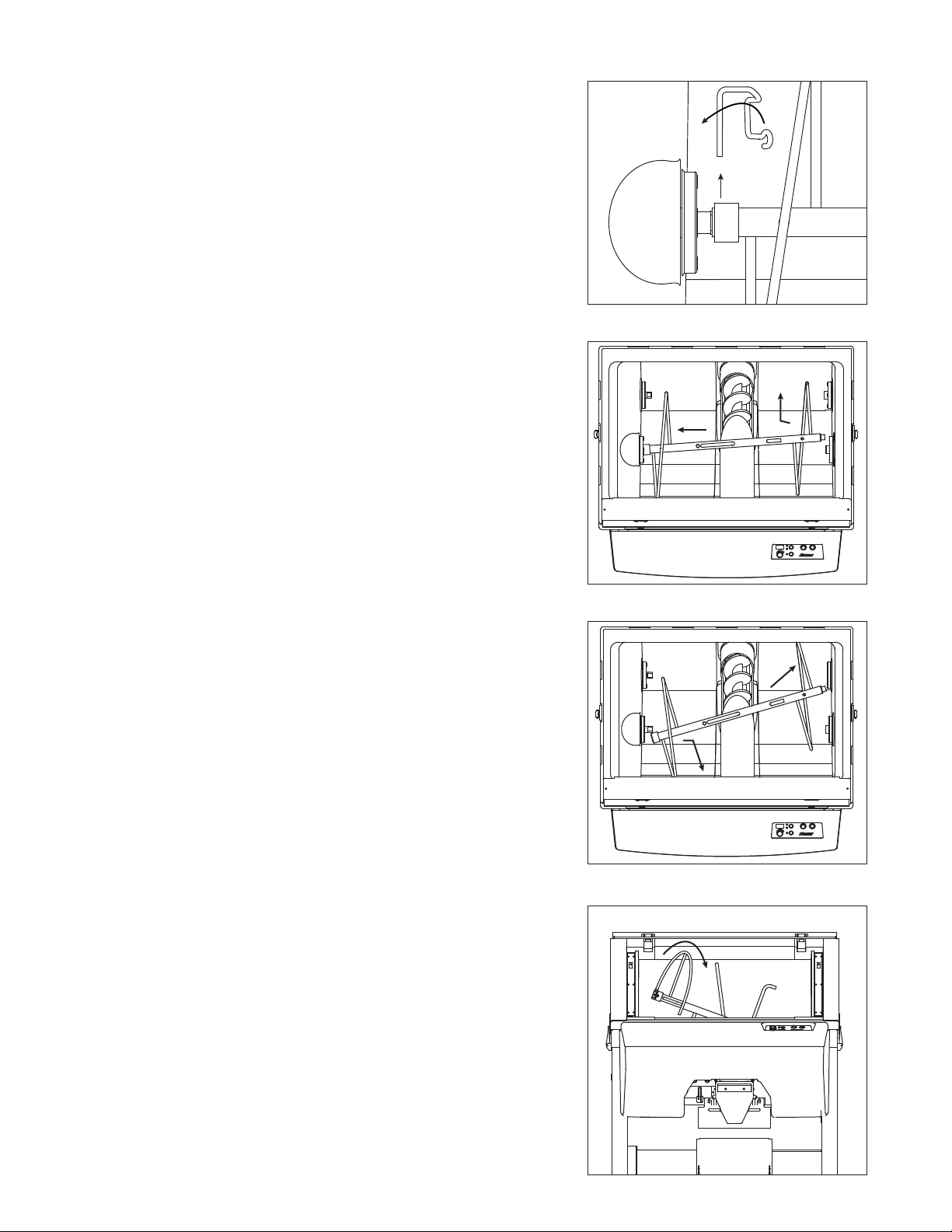
Agitator removal
1. Remove all ice from dispenser.
2. Disconnect power to dispenser and icemaker.
3. Remove window from upper ice storage section.
4. Remove connection pin from left side of agitator bar (Fig. 20).
5. Move agitator bar toward left dispenser wall (Fig. 21.1) while
pulling out the right side from bearing (Fig. 21.2).
6. Push right side of agitator bar toward rear right corner of bin
(Fig. 22.1) while pulling out the left side from the drive shaft
(Fig. 22.2).
7. Position pin end of agitator in window frame and spiral clockwise
out opening (Fig 23).
Fig. 20
Fig. 21
2
1
Fig. 22
1
2
Fig. 23
15
Page 16
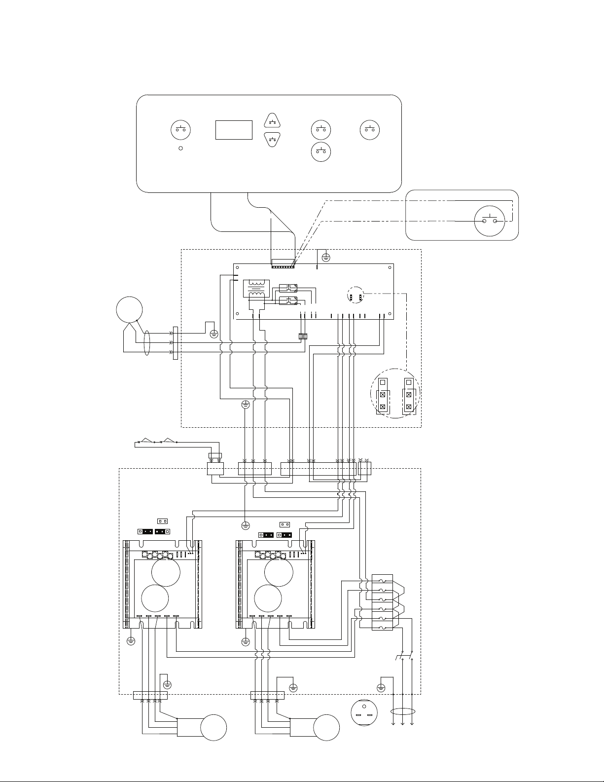
Wiring diagram
DB1000 - ICE PRO SCHEMATIC
DB1000SA - ICE PRO SCHEMATIC
OPERATOR INTERFACE
PB6
BAG OPEN
START/STOP
PB5
TIMED MODE
INCREASE
PB3
TIMED MODE
START/STOP
DB1000SA
BLOWER MOTOR
SA VERSION
M3
63 GRN/YEL
6.0
LED1
BLOWER MOTOR
ON INDICATOR
UPPER OPERATOR CONSOLE BOX
66 GRN/YEL
62 WHT
61 BLK
65 WHT
64 BLK
J4J3
SAFETY
PB4
TIMED MODE
DECREASE
220/240
VAC
J1
J2
1 AMP
FUSE 8
1 AMP
PIN 1
BLOWER
MOTOR
5 GRN/YEL
J14
J15
33 BLK
34 WHT
PB2
TIMED MODE
STOP
J21
GND
AUGER
650
J12
J13
FUSE 7
1 AMP
CONTROL BOARD
AUG
COM
1000
J8
J9
J29
J10 24-RED P21-7
J9 30-RED P21-9
J29 29-BLK P21-8
UPPER
LOWER
AGIT650
AGIT
J11
J10
J30
J30 23-BLK P21-6
PB1
MANUAL
START/STOP
FOOT
SWITCH
J5
J6
J31
BROWN
BLUE
1
ENLARGED JUMPER SETTINGS
1
J22
J24
46 BLK
47 BLK
DB1000 START/STOP
WINDOW SWITCH
LOWER CONTROL BOX
50/60HZ
X2
UVWL1L2
4 GRN
25 BLK J23-2
26 WHT J23-3
27 RED J23-4
28 GR J23-5
P23-5
P23-4
P23-3
P23-2
A/M
X1
15 BLK
37 BLK
16WHT
AUGER
MOTOR
L1-T1-T7
L2-T2-T8
L3-T3-T9
54 BLK
55 RED
J26
38 RED
AUGER
CONTROL
FSR
P1P2P3
T4-T5-T6
M2
J22
10 GRN
UVWL1L2
3 GRN
21 RED J24-3
P24-3
32 BLK TO J21-2
31 BLK TO J21-1
50/60HZ
20 WHT J24-2
19 BLK J24-1
P24-2
P24-1
X2
17 BLK
GRN
P24-4
9 WHT J22-2
8 BLK J22-1
A/M
X1
35 BLK
18WHT
22 GRN-J24-4
AGITATOR
MOTOR
L1-T1-T7
L3-T3-T9
L2-T2-T8
P1P2P3
36 RED
FSR
T4-T5-T6
J21
AGITATOR
CONTROL
M1
18 WHT
17 BLK
FOOT
SWITCH
J27
6
6 BLK J21-5 J27-1
7 WHT J21-4 J27-2
NEMA 6-15
7
FUSE
BLOCK
F1-10A
F2-10A
F3-5A
F4-10A
F5-10A
F6-5A
MAIN
POWER
SWITCH
G
1Ø 240VAC
12 BLK
11 BL K
2
1
L1
INPUT
14 WHT
13 WHT
1 BLK
BROWN
L2
2 WHT
5
4
BLUE
53 BRN
52 BLU
50 BLK
51 WHT
59 WHT
58 BLK
60 GRN
WINDOW SWITCH
16
Page 17

Before calling for service
1. Check that ice is in the dispenser and that congealed cubes are not causing a jam.
2. Check that circuit breaker and switches are in ON position.
3. Check that window is on securely. If ajar, dispenser will not operate.
4. Check that all drains are clear.
Troubleshooting guide
Symptom
Ice does not dispense
Possible cause
1. No ice in bin
2. Dispense switch not closing
3. Foot pedal not closing
4. Auger motor not operating
5. Agitator motor not operating
6. Both auger motor & agitator
motor not operating
Solution
1. Check operation of ice maker
2. Check for contract closure
3. Check for contact closure of switch inside
foot pedal enclosure
4A. Check for power to motor
4B. Check for output from corresponding inverter
4C. Check fuses and power supply to LI & L2 of inverter
4D. Jump terminals F & S on inverter. If motor runs,
replace PC board
Note: Voltage from inverter and auger motor must be
tested with an analog meter
5A. Check for power to motor
5B. Check for output from corresponding inverter
5C. Check fuses and power supply to LI & L2 of inverter
5D. Jump terminals F & S on inverter. If motor runs
replace PC board
Note: Voltage from inverter and auger motor must be
tested with an analog meter
6A. Check that window is in place
6B. Check that both window interlock switch are
fully depressed
6C. Check that interlock relay is energized
Bags tear off pins
during filling
More than one bag opens
when blower is on
Bags won’t open
1. Bag platform not adjusted
properly
2. Poor quality bags
1. Stainless steel chute is not
resting against bags
1. Blower switch not on
2. Blower duct missing or out
of position
3. No power to blower motor
1. Adjust bag platform to on notch above where bottom
of bag contacts platform
2. Try bags from another supplier
1. Move chute lever to up position to locate stainless
steel chute in the rear position
1. Turn blower switch on
2. Reinstall/re-position blower duct
3. Check fuses and output power at operator
control panel
If problems persist after following this basic troubleshooting guide, call Follett’s technical
service department at (877) 612-5086 or (610) 252-7301.
17
Page 18
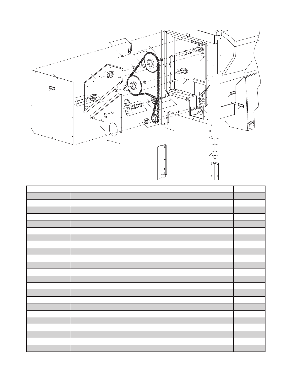
Replacement parts
2
8
1
3
10
21
6
12
3
14
7
22
14
17
18
15
15
16
16
9
11
20
5
19
13
4
21
21
Reference # Description Part #
1 Panel, access, side 00109751
2 Latch, hopper 00109769
3 Tensioner (includes 00109868) 00109777
4 Bearing (includes 00109876) 00109785
5 Sprocket, agitator (includes 00101048) 00109793
6 Sprocket, drive 00109801
7 Sprocket, idler (includes 00109884) 00109819
8 Frame, outer bearing support (includes (2) 00109785, (2) 00109876) 00109827
9 Hardware, mounting, agitator motor 00109835
10 Motor, agitator (includes 00109835) 00109843
11 Leg, extension (one) (includes 00104315) 00109850
12 Hardware, mounting, tensioner (set of 2) 00109868
13 Hardware, mounting, bearing (set of 2) 00109876
14 Hardware, mounting, idler wheel (set of 2) 00109884
15 Key, coupling, drive 00101048
16 Coupling, drive (includes 00101048) 00105825
17 Chain 208652
18 Bushing, bronze 00104372
19 Shim 00104786
20 Insert, leg 00104315
21 Handle, insert 00104299
22 Leg, standard (includes 00104315) 00111021
Not shown Hardware, leg mounting (set of 4) 00109900
18
Page 19
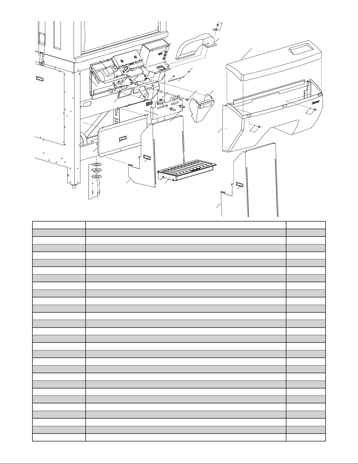
21
11
7
24
16
20
25
17
14
18
2
3
5
5
13
6
15
12
10
9
19
5
4
23
23
26
15
22
8
1
Reference # Description Part #
1 Hood, dispense 00109918
2 Cover, dispense (includes 00111039) 00109926
3 Bag stand (includes (2) 00104299) 00109934
4 Drain pan 00925503
5 Handle, insert 00104299
6 Panel, access, front (includes 00104299) 00109959
7 Chute, outer, dispense 00109967
8 Bracket, bag hanger (includes (2) 208626, (2) 208940, (2) 500915) 00109975
9 Chute, inner, dispense 00109983
10 Actuator, chute (includes 00111062) 00109991
11 Duct, blower (includes 00111070) 00110007
12 Panel, access, side 00109751
13 Fitting, drain 00110023
14 Motor, auger (includes 00110080) 00110031
15 Blower 00110049
16 Shaft, pivot, inner chute (includes (2) 00111070) 00110056
17 Bracket, blower/control box 00110064
18 Bracket, auger drive (includes 00110304) 00110072
19 Bag stand, extended (includes (2) 00104299) 00111054
20 Cotter pin 208892
21 Mounting hardware, air duct 00111070
22 Pin, bag support 208626
23 Mounting hardware, dispense cover 00111039
24 Thumbscrew 500915
25 T-nut 208940
Not shown Hardware, mounting, auger motor (set of 4) 00110080
Not shown Collar, dispense feed 00102970
Not shown Screw, Nylok (8 required) 208755
19
Page 20
20
15
24
12
16
14
11
19
19
18
21
22
1
8
2
2
23
17
23
5
4
6
10
8
3
9
7
1
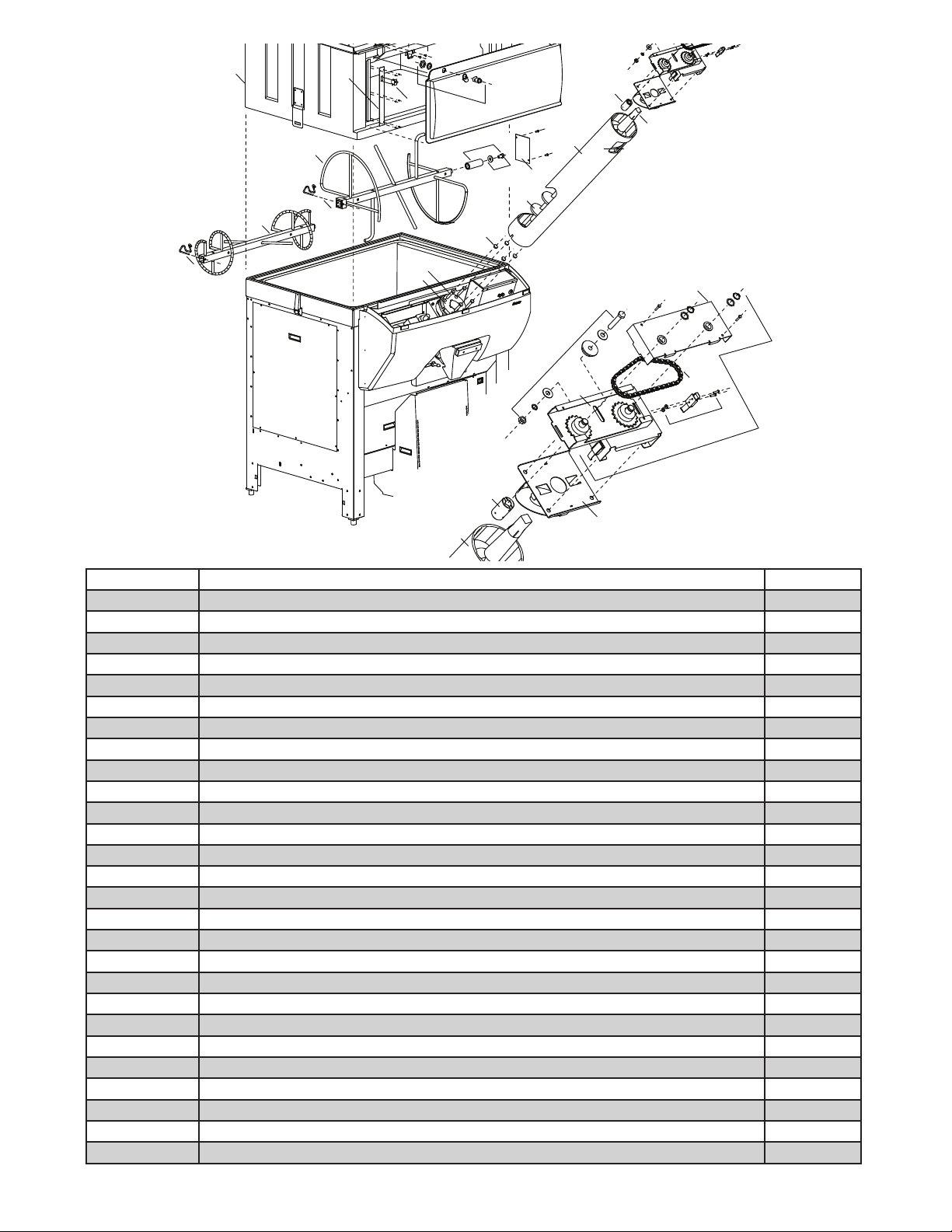
Reference # Description Part #
1 Tube, auger 00100958
2 Auger 208816
3 De ector, ice 00110106
4 Plate, lower, auger drive 00110114
5 Plate, cover, auger drive 00110122
6 Chain, auger drive 208935
7 Latch, auger drive 00110148
8 Coupling, auger motor 00110155
9 Transmission, auger drive (includes 00110114, 00110122, 00110130, 00110155, 00110171) 00110163
10 Tensioner, auger chain 00110171
11 Agitator, lower (includes 00110262) 00110189
12 Agitator, upper (includes 00110262) 00110197
13 Window, inspection (includes 00110213) 00110205
14 Latch, window 00110213
15 Catch, window 00110221
16 Switch, safety 208810
17 Bearing, auger (includes 00110296) 00110247
18 Bearing, agitator (includes 00110270) 00110254
19 Pin, lock, agitator 00110262
20 Cover, switch plate 00101345
21 Hardware, mounting, agitator bearing 00110270
22 Plate, access, agitator bearing 00110288
23 Hardware, mounting, auger bearing (set of 4) 00110296
24 Hopper, upper section (includes 00110205) 00111096
Not shown Bracket, brush, hopper cleaning 00115949
Not shown Brush, hopper cleaning 00107839
Not shown Pole, extension, brush 00107821
20
Page 21
3
9
4
2
5
1
6
7
8
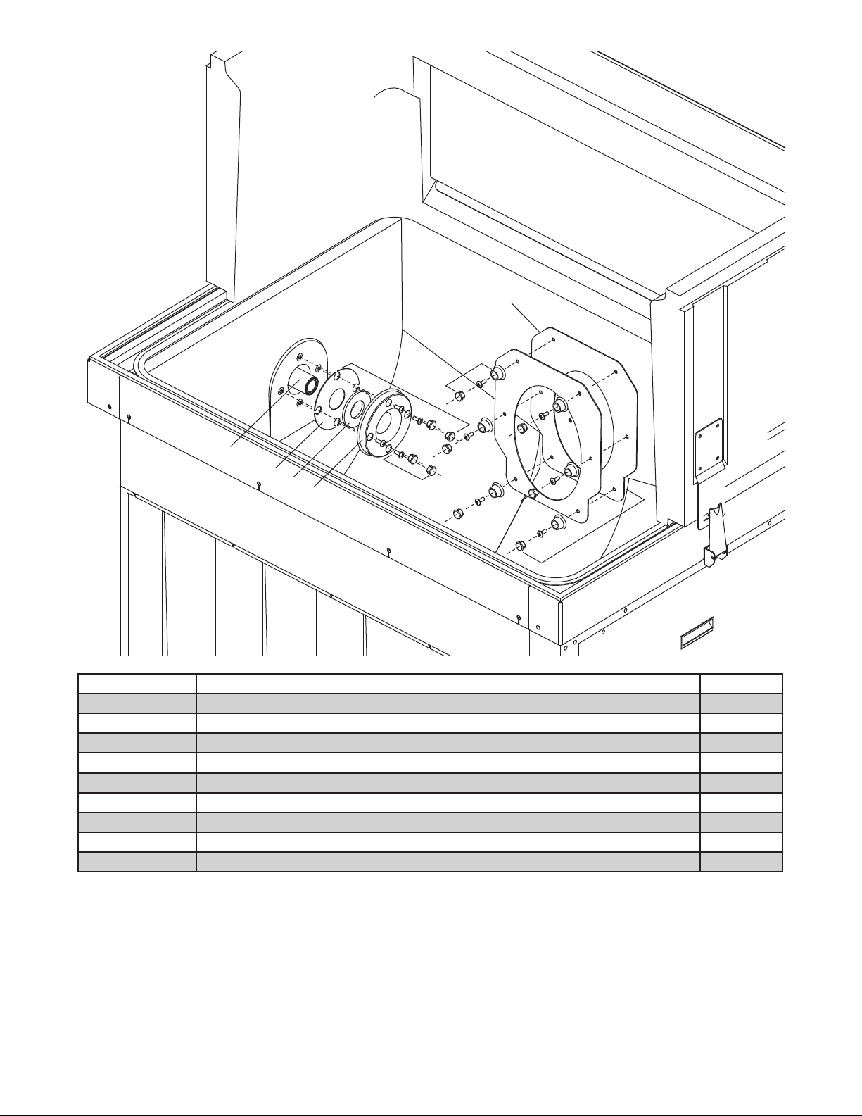
Reference # Description Part #
1 Bearing, agitator support 00110254
2 Kit, shaft seal, agitator (includes 00110338) 00110312
3 Gasket, tube seal, auger 00102061
4 Kit, tube seal, auger (includes 00102061, 00110346) 00110320
5 Base, seal 00101246
6 Seal, agitator 00103911
7 Collar, seal 00101535
8 Hardware, mounting, shaft seal (set of 4) 00110338
9 Hardware, mounting, tube seal (set of 6) 00110346
21
Page 22
2
5
1
4
3
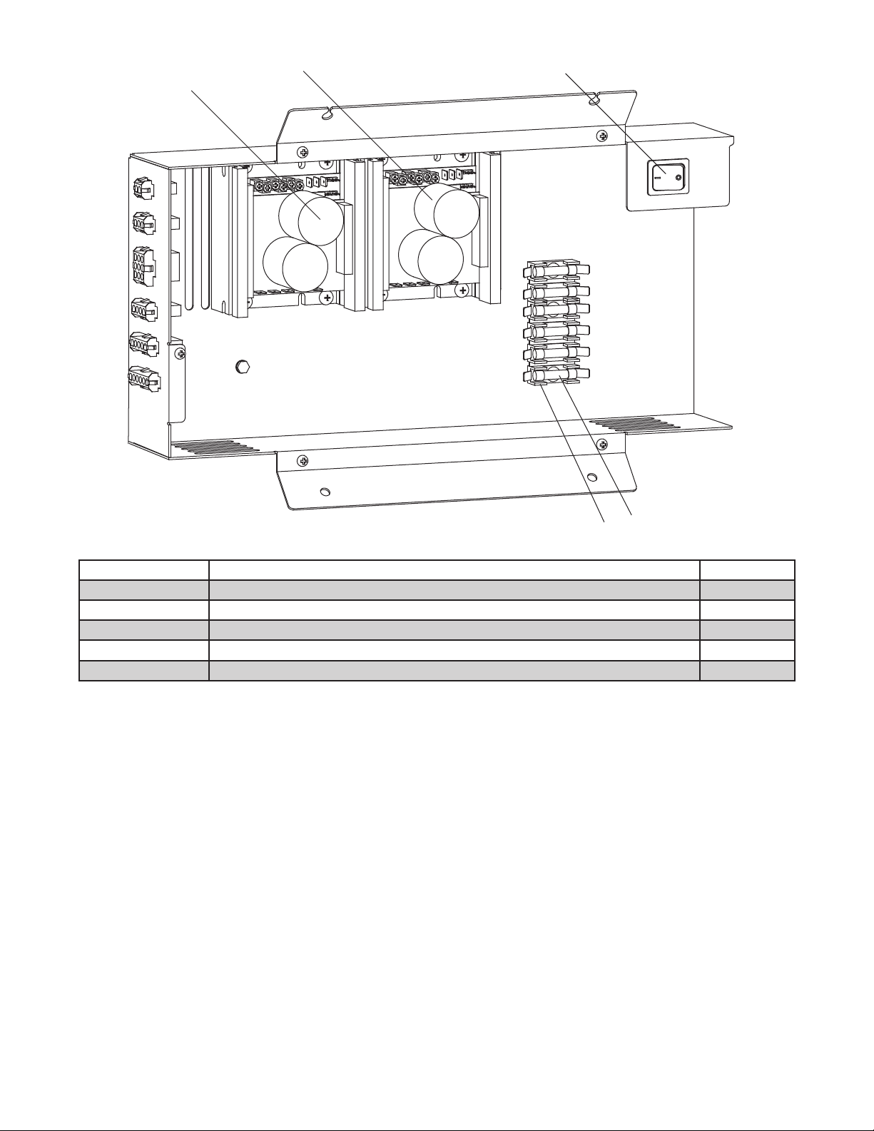
Reference # Description Part #
1 Inverter, auger 00925651
2 Inverter, agitator 00925651
3 Fuse holder 00105411
4 Fuse, 10 amp 208823
5 Switch, rocker 208867
22
Page 23
DB1000-SA DB1000
3
5
2
3
1
2
1
5
4
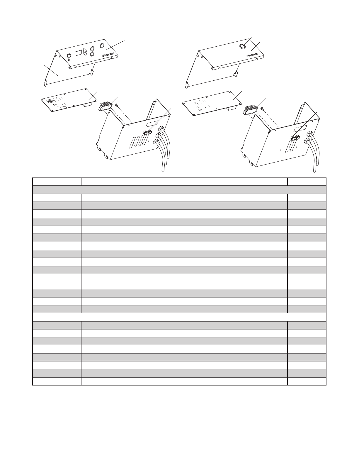
Reference # Description Part #
DB1000–SA
1 Control board (Serial # above D51557) 00924597
1 Control board, green display (before Serial # D51558) 00104521
Control board (red display) – obsolete. Use retro t kit 00129833 below.
2 Terminal strip 00110411
3 Membrane switch 00902270
3 Label, green display (before Serial # D51558) 00106054
4 Fuse holder 208915
5 Cover, console (green display – includes 00106054) 00129858
Not shown Fuse, 1/4 amp 208825
Not shown Fuse, 1 amp 208826
Not shown Retro t kit, control board, green display (includes 00129858, 00104521,00105429 and
00101212)
Not shown Control knob (before Serial # D51558) 00105528
Not shown Switch, stop (before Serial # D51558) 00105429
Not shown Switch, start (before Serial # D51558) 00101212
DB1000
1 Control board (Serial # above D51557) 00924597
1 Control board (before Serial # D51558) 00106922
2 Switch, start 00101212
3 Label, console 00102020
4 Fuse holder 208915
Not shown Fuse, 1/4 amp 208825
5 Terminal strip 00110411
Not shown Switch, foot 00115055
00129833
4
23
Page 24

801 Church Lane • Easton, PA 18040, USA
Toll free (877) 612-5086 • +1 (610) 252-7301
www.follettice.com
00109710R10
03/12
 Loading...