

Page 1
Digital
Option
OctoPre Digital Option Operation Guide
Overview
The OctoPre digital interface card contains 8 separate
analogue to digital converters allowing all 8 OctoPre
channels to be accessed simultaneously on the rear panel
as either analogue or digital signals. The interface card is
available in two feature options: -
1. AES/SPDIF/ADAT™
The 8 channels of the OctoPre are converted
simultaneously to either AES or SPDIF standard and to
ADAT™ standard.
2. ADAT™
The 8 channels of the OctoPre are converted only to
ADAT™ standard.
These instructions refer to both feature options. Note:
Where the instructions refer to features that are only
available on the “AES/SPDIF/ADAT™” version these will
be marked with an “*”.
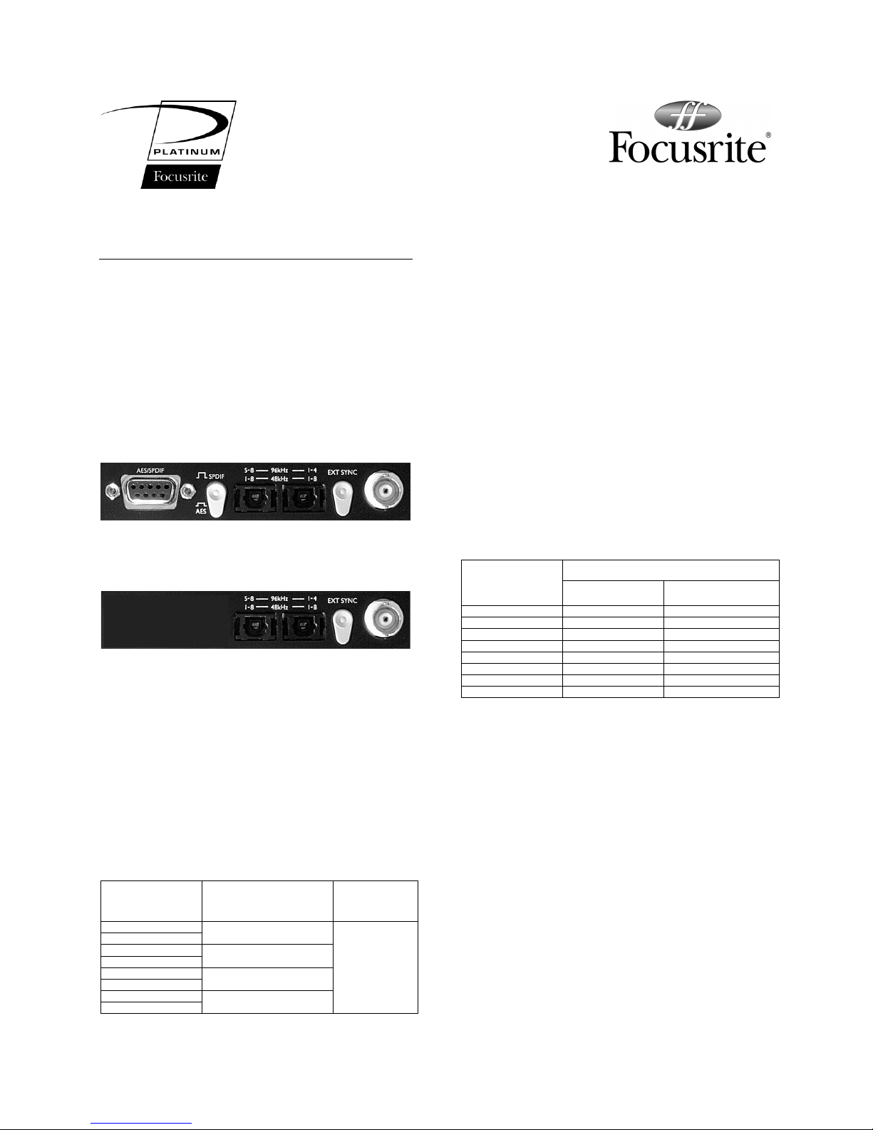
Digital Outputs
*AES
The 8 channels of OctoPre audio in AES digital format are
made accessible by connecting the AES cable to the 9 pin
D-type connector and switching “out” the AES/SPDIF
switch on the rear panel. The AES cable has four colour
coded XLR type connectors, each carries a pair of digital
audio channels as follows: -
OctoPre Channel
Number (Analogue
Output)
AES/SPDIF Connector Ring
Colour
Channel label in
digital stream.
12BLACK
34RED
56YELLOW
78BLUE
A
B
A
B
A
B
A
B
*SPDIF
The 8 channels of OctoPre audio in SPDIF digital format
are made accessible by connecting the SPDIF cable to the 9
pin D-type connector and switching “In” the AES/SPDIF
switch on the rear panel. The SPDIF cable has four colour
coded Phono/RCA type connectors and pairs of digital
audio are sent down each cable, see above for colour to
channel identification.
ADAT™
The 8 channels of OctoPre audio in ADAT™ format are
made accessible via two light pipe sockets. The function of
these connectors is dependent upon the sample rate set
for digital conversion on the front panel. At either
44.1KHz or 48KHz sample rates both sockets transmit all
8 channels of digital audio simultaneously giving two
identical parallel outputs of all 8 channels. At either
88.2KHz or 96KHz sample rates the digital outputs are
spread across the two connectors as follows: -
Audio transmitted in digital stream
OctoPre Channel
Number (Analogue
Output)
Sample Frequency
44.1KHz or 48KHz
Sample Frequency
88.2KHz or 96KHz
111 (1-4 connector)
222 (1-4 connector)
333 (1-4 connector)
444 (1-4 connector)
551 (5-8 connector)
662 (5-8 connector)
773 (5-8 connector)
884 (5-8 connector)
Note: The operation of splitting the 8 channels of
88.2/96KHz digital audio across two light pipe sockets
conforms to the S/MUX2 standard. This standard is
required for the ADAT™ connectors to transmit at
88.2/96KHz because of a limitation in the transmission
speed of the original ADAT™ standard. The S/MUX
2
standard of operation can only be used when connecting
to equipment capable of receiving audio data conforming
to this standard, check your equipment operating
instructions for compatibility.
S/MUX2 is the copyright of Sonorus Inc, Newburgh, NY, USA
ADAT™ is the trademark of Alesis Corp
Page 2
Rear Panel Controls
EXT SYNC Switch
Pressing “In” the EXT SYNC switch forces the 8 OctoPre
analogue to digital converters to synchronise to the clock
signal connected to the rear panel BNC style connector.
Note: When using an external clock source always select
the front panel frequency switch to match the sample rate
of the incoming signal. Without this the unit cannot lock to
the external clock signal.
*AES/SPDIF Switch
When the switch is in the “In” position the digital signals
present at the 9 pin D Type connector conform to the
“Professional” AES digital format standard. When the
switch is in the “Out” position the digital signals present at
the 9 pin D Type connector conform to the “Consumer”
SPDIF digital format standard.
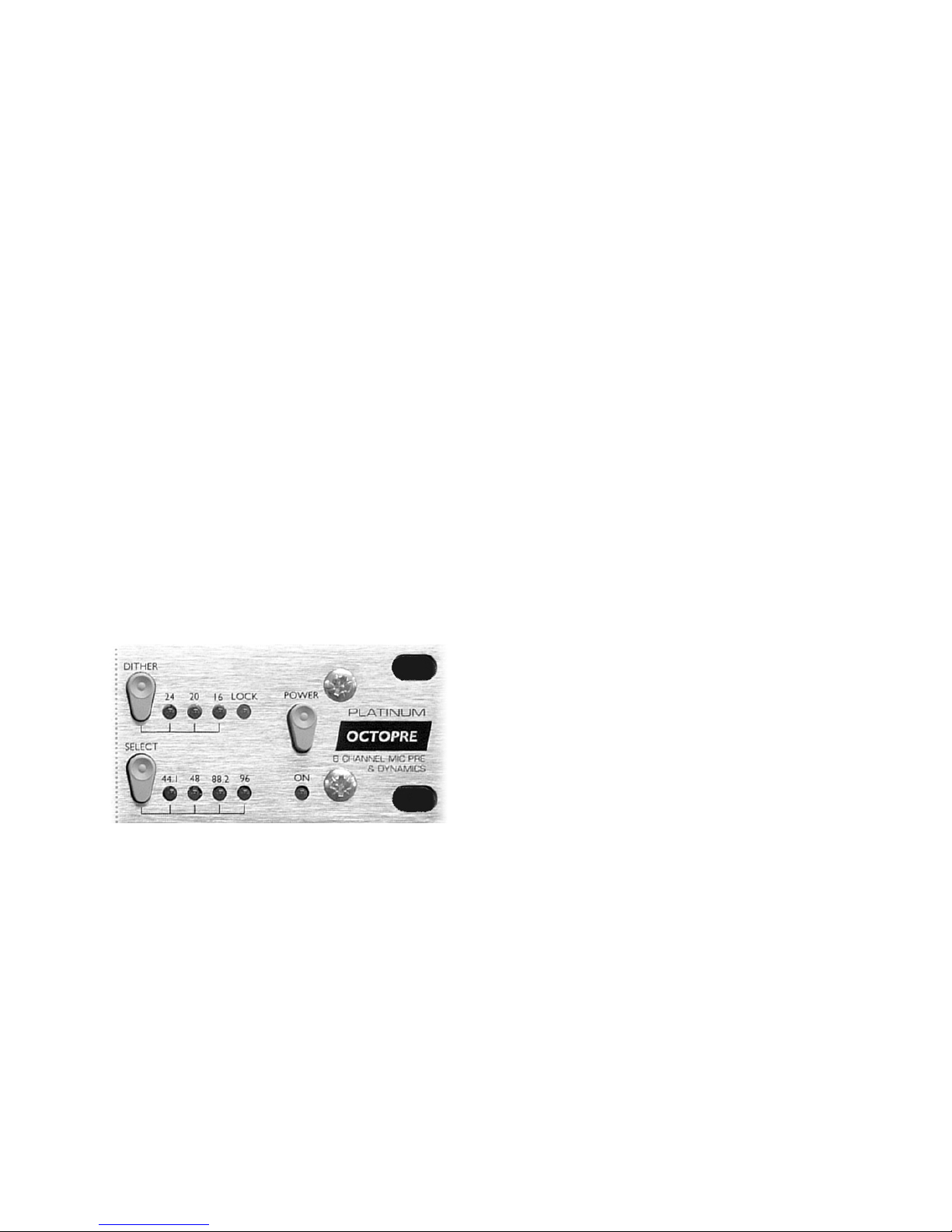
Front Panel Controls
When the digital interface card is fitted into the OctoPre,
the Frequency Select and Dither switches and indicators
become active.
Frequency Select
Pressing the SELECT switch increments the converter
sample frequency from 44.1KHz through to 96KHz, when
either 88.2KHz and 96KHz is selected the operation of the
ADAT™ sockets automatically switch to the S/MUX
2
operation.
Dither
Pressing the DITHER switch selects the digital output
word length to either 24, 20 or 16 bit, this is achieved by
dithering the converted signal and truncating the unused
bits.
Lock Indicator
The lock indicator is lit when the rear panel EXT SYNC
switch is pressed in and the unit is synchronised to the
incoming signal connected to the BNC connector.
Note: In case of discontinuity in the external clock
connection or extreme variation in external clock
frequency the OctoPre Lock indicator may switch off
indicating the unit has lost lock. To recover lock in this
situation, re-select the correct sample frequency from the
OctoPre front panel.
Audio Operation
The signal which is converted to digital is taken just before
the analogue output where 0dBfs (the maximum level
before digital overload) is equivalent to a 21dBu level at
the analogue output. The maximum analogue level can be
prevented from exceeding 0dBFs by using the channel
dynamics controls - see the OctoPre user guide for full
instructions.
www.focusrite.com
 Loading...