

Page 1
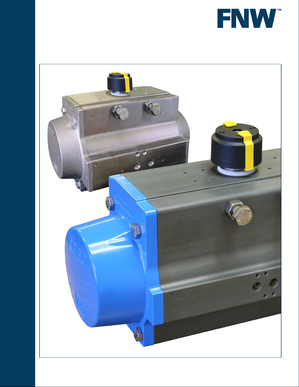
Figure RP
ACTUATORS
PNEUMATIC RACK & PINION
www.fnw.com
Page 2
TORQUE RANGES
The RP rack and pinion actuators are
available with output torques ranging
from 44 to 36,269 in-lbs depending on
air supply pressure and/or spring sets.
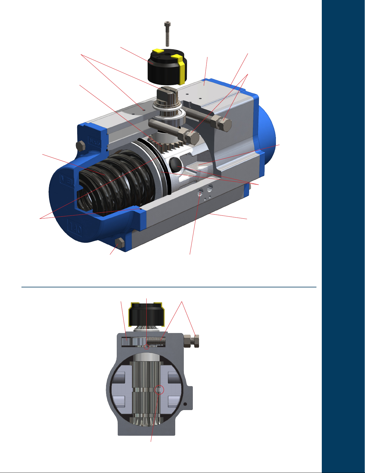
ACCESSORY MOUNTING
The accessory mounting pad meets
international NAMUR standards for
ease of directly attaching accessories
following the same standard.
ANTI BLOW-OUT PINION
The design of the pinion prevents
blow out by securing it with the piston
racks. The pinion is ground from
hardened steel and then nickel plated
for maximum corrosion and wear
resistance.
SPRINGS
For fail safe requirements,
reliable and high resistant
steel springs are included.
Springs are zinc phosphate
coated for corrosion
resistance.
SEALS
The standard
actuator is
supplied with NBR
seals at piston, pinion,
and end caps. Viton® is
available for high temperature
applications, and Silicon for low
temperature applications.
Standard Features
POSITION INDICATOR
High visibility position indicator with
snap on marks is easily converted to
indicate 3-way positions or can be
removed for other accessories.
END CAP SCREWS
End caps are secured with extra
length stainless steel screws for safe
disassembly.
ACTUATOR BODY
The body is a single piece extruded
aluminum housing with anodized
hard coat exterior nished to 45-50
microns. An optional nickel plated
exterior is available for added
corrosion resistance.
SOLENOID MOUNTING
Supply air connections follow the
international NAMUR standard for
direct mounting of like style solenoids
and is included on all sizes.
END CAPS
Ends caps are die cast aluminum with
polyester powder coating. Nickel
plated bodies also come with nickel
plated end cap. Double-acting
and spring-return actuators utilize
the same end caps, allowing quick
conversion by adding or removing
springs as needed.
TRAVEL STOPS
Each size actuator comes standard
with two travel stops for +/-5° of open
and close travel adjustment at
nominal positions of 0° and
90°. The stainless steel
adjustment screws and cam
are not located in the main
pressure containing
area of the body,
reducing the number
of possible leak
paths and necessary
seals.
PISTONS
Pistons are
constructed of die
cast aluminum and
designed for strength
and generous rack
engagement.
PISTON GUIDES
Piston guides, constructed from
POM materials, are designed with
a large contact area and long life.
The material offers low friction for self
lubrication.
VALVE MOUNTING
The valve mounting follows ISO 5211
for direct mounting to valves with the
same pattern. All output drive include
an 8-point female drive (except the
model 270 which has a single square
4-point female drive).
Travel Stops
The travel stop cam is located separate
from the pressure chamber of the
actuator. This design eliminates two
potential leak paths as well as the
associated seal components. The cam
is positively locked to the pinion and
easily installed during maintenance
via a guide in the cam chamber. The
cam chamber is a sealed compartment
that is protected from water and
dirt ingress, ensuring trouble free
operation.
Anti-Blowout Pinion
The RP actuators is designed with a
grooved pinion and a corresponding
at key cast in the piston rack. This
system creates an added mechanical
lock that prevents the pinion from
blowing out of the bottom of the
housing. In this design, lower pinion
clips and retainers that can wear out
are eliminated.
2
CAM STOP BOLT
GUIDE
PINION / PISTON GROOVE
Standard Materials
• Body - UNI 6060 Aluminum, Hard Anodized
(Optional Nickel Plating)
• End Caps - Die Cast Aluminum, Polyester
Powder Coated (Nickel plated with nickel plated
body)
• Pinion - Hardened Steel, Nickel Plated
• Pistons - Die Cast Aluminum
• Seals - NBR (Optional High Temperature Viton®
or Low Temperature Silicon)
• Guides/Spacers/Anti-Friction Rings - POM
(Acetal) (Model 270 uses PTFE and Graphite
Filled PTFE anti-friction rings)
• Travel Stops/Cam/End Cap Screws - Stainless
Steel
• Springs - Steel, Zinc Phosphate Coated (Spring
return models only)
• Position Indicator - Nylon
• Travel Stop Housing - GGG40 Ductile Iron
(Model 270 only)
• Upper Pinion Snap Ring - Steel, Nickel Plated
Page 3
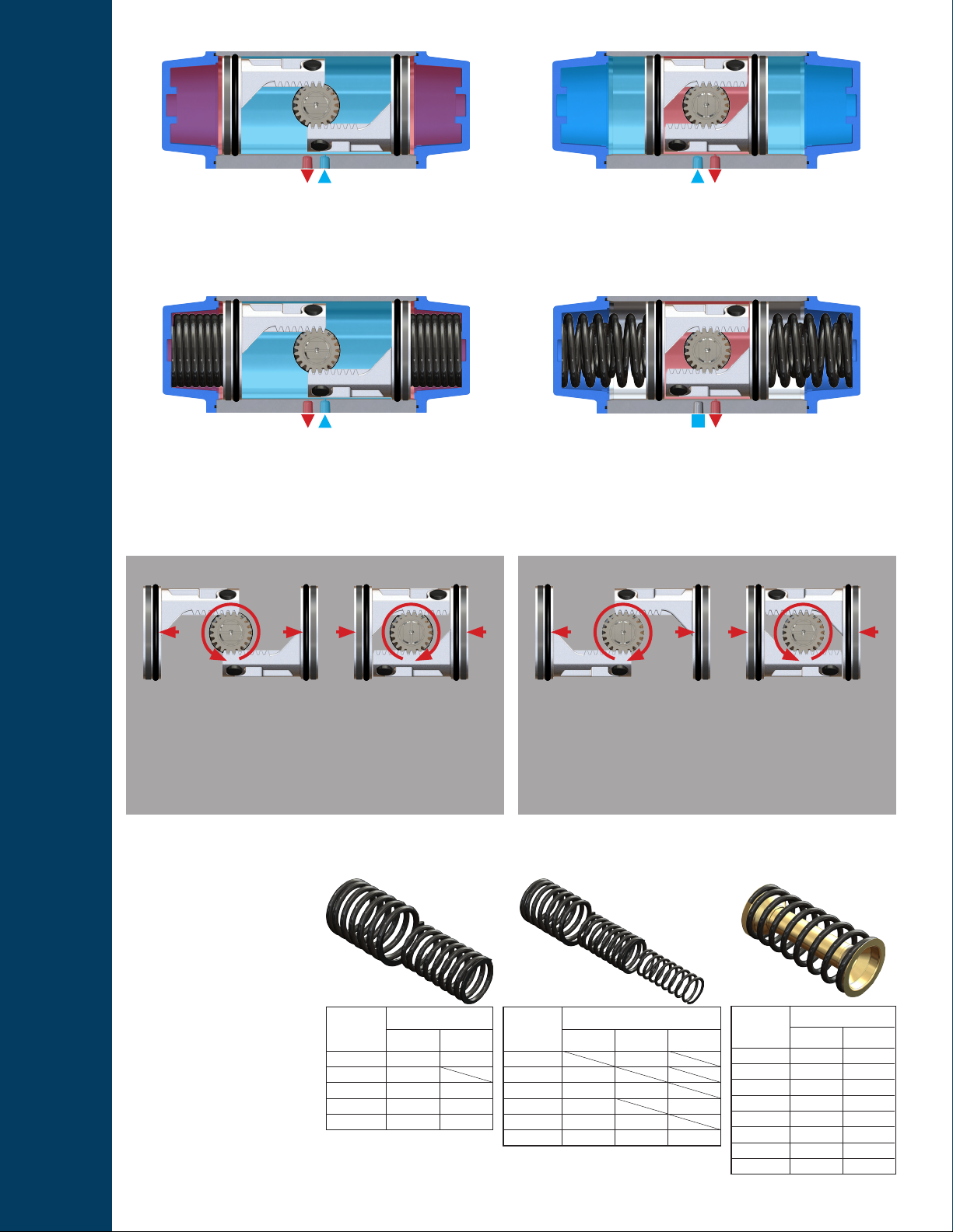
Standard Operation - Double Acting
AB AB
The RP rack and pinion actuator operates (turns) CCW by
supplying compressed air to port A. The pressure drives the
pistons outward, turning the drive pinion CCW. Air on the
outside of the pistons is exhausted out of port B.
Standard Operation - Spring Return
The RP rack and pinion actuator operates (turns) CW by
supplying compressed air to port B. The pressure drives the
pistons inward, turning the drive pinion CW. Air on the inside of
the pistons is exhausted out of port A.
AB
The RP rack and pinion actuator operates (turns) CCW by
supplying and holding compressed air at port A. The pressure
drives the pistons outward, turning the drive pinion CCW and
compressing the spring sets. Air on the outside of the pistons is
exhausted out of port B.
Reversible Operation
Standard Rotation Reversed Rotation
CWCCW
In the standard operation of the RP actuator, the output turns
CCW when the pistons are driven outwards. When the pistons
are driven inwards, the output turns CW. This is the typical
action of the majority of valves that open in the CCW direction,
and close in the CW direction.
Spring Return Spring Set Congurations
The RP rack and pinion
actuators are stocked with full
spring sets (spring set 05 for
models 52 to 140, spring set
06 for models 160 to 230, and
spring set 08 for the model
270).
Spring sets can be modied by
removal of springs, as indicated
in the spring set charts, to alter
the actuator’s torque curve as
shown on the torque charts.
Full spring sets provides the
maximum spring return torque
for a given size actuator, but
can be reduced for situations
where increased torque in the
air stroke is desired.
Spring
Set
01 1 1
02 2
03 1 2
04 2 1
05 2 2
Outer
Inner
Spring Quantity
Outer Inner
* Model 230 has maximum spring set of 06.
AB
The RP rack and pinion actuator operates (turns) CW by
releasing the compressed air at port A. This allows the spring
sets to decompress as they drive the pistons inward and the
pinion turns CW. Make-up air is drawn in through port B from
the atmosphere.
CCWCW
The RP actuator operation is eld reversible so the output turns
CW when the pistons are driven outwards, and CCW when they
are driven inwards. This conguration is used for spring return
actuators that require a mechanical fail in open position, or for
valves with reversed operation.
Models 160 to 200Models 52 to 140
Outer
Middle
Spring
Set
Spring Quantity
Outer Middle Inner
01 2
02 2
03 1 2
04 2 2
05 2 2
06 2 2 2
Inner
Models 230* & 270
Pre-tensioned
Spring
Set
Springs/Side
Side A Side B
01 2 3
02 3 3
03 3 4
04 4 4
05 4 5
06 5 5
07 5 6
08 6 6
Spring
3
Page 4
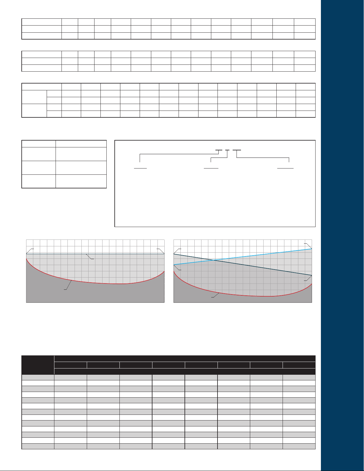
Weight (Pounds)
Model 52 63 75 85 100 115 125 140 160 180 200 230 270
Double Acting
Spring Return
2.47 3.66 6.13 8.60 12.13 19.51 23.81 35.94 47.95 63.93 81.57 128.97 182.26
2.87 4.34 7.47 10.58 15.43 25.24 31.04 47.40 65.04 87.96 121.25 156.53 221.06
Air Consumption Per Stroke (Cubic Inches)
Model 52 63 75 85 100 115 125 140 160 180 200 230 270
CCW (DA & SR)
CW (DA)
6.10 11.59 21.97 31.12 48.21 78.72 99.47 137.91 220.30 282.54 347.84 651.73 915.36
7.93 14.04 26.85 39.06 61.02 104.35 134.86 192.84 306.34 402.76 643.80 918.41 1,086.22
Stroke Speed (Seconds)*
Model 52 63 75 85 100 115 125 140 160 180 200 230 270
Double
CCW
Acting
Spring
CCW
Return
* Note: Stroke speeds listed are based on actuator alone (no valve) with 6 Bar (87 PSI) supply air pressure. Valve torques and ow characteristics of control accessories
will have an affect on overall stroke speed.
Temperature Ranges
Conguration Working Temperature
Standard
High Temp.
Low Temp.
High and low temperature congurations must be
specied separately.
0.07 0.11 0.18 0.36 0.38 0.60 0.80 1.13 1.43 1.99 3.08 4.15 6.16
0.05 0.10 0.15 0.25 0.34 0.54 0.70 0.94 1.25 1.80 2.41 3.80 5.47
CW
0.07 0.13 0.32 0.32 0.54 0.92 1.20 1.64 2.27 3.08 3.58 6.20 8.97
0.07 0.13 0.22 0.30 0.48 0.75 0.94 1.25 1.60 2.38 2.80 5.40 6.62
CW
Model Number Matrix
-4° to 185°F
(-20°C to 85°C)
-4° to 302°F
(-20°C to 150°C)
-40° to 185°F
(-40°C to 85°C)
52
63
75
85
100
115
125
SIZES
140
160
180
200
230
270
A = Anodized Aluminum
(with polyester powder coated end caps)
N = Nickel Plated
(with nickel plated end caps)
Actuators stocked standard for CCW rotation at supply port A, CW rotation at supply
port B. Standard spring return conguration is fail CW on loss of supply air. Spring
return actuators stocked with full (maximum) spring sets. When applications require
it, rotation, fail position, and spring sets can be modied, but must be specied
separately.
FNW RP 52 A DA
FINISH
DA = Double Acting
SR = Spring Return
ACTION
Double Acting Actuator Sizing
Air Stroke Start Air Stroke End
Actuator Torque Curve
TORQUE
Valve Torque Curve
0
The gure RP double acting rack and pinion actuator has a constant torque output.
This is represented by the horizontal line in the diagram. Sizing is simply a matter
of selecting the column for the amount of supply air pressure available for the
actuator, then choosing the actuator that has more torque than the highest torque
requirement of the valve plus a safety factor. Any amount of torque between the
valve and actuator’s torque curve is the safety factor and that percentage should be
chosen based on the type of valve and working conditions.
VALVE POSITION / DEGREES OF ROTATION
Safety Factor
90
Spring Return Actuator Sizing
Air Stroke Start
Actuator Spring Stroke Curve
Actuator Air Stroke Curve
Spring Stroke End
TORQUE
Safety Factor
Valve Torque Curve
0
The torque output of the gure RP spring return actuators is not constant,
but decreases during both the air stroke and spring stroke due to losses from
compression and decompression of springs. When sizing, care must be taken
to select an actuator whose end-of-air and end-of-spring stroke torque is greater
than the valve’s torque plus a safety factor. The RP has maximum spring strength
as standard, but lower spring sets can be obtained by removing the appropriate
springs.
VALVE POSITION / DEGREES OF ROTATION
Double Acting (Air-Air) Torque Chart
Air Supply Pressure (PSI)
Model
52 88 112 133 158 178 201 227 263
63 152 193 238 282 320 361 405 469
75 283 356 435 513 586 659 736 851
85 406 514 628 744 853 960 1,072 1,237
100 645 814 989 1,163 1,333 1,505 1,681 1,939
115 1,065 1,344 1,640 1,932 2,212 2,488 2,779 3,211
125 1,402 1,771 2,153 2,539 2,905 3,274 3,650 4,220
140 2,003 2,504 3,005 3,506 4,006 4,509 5,009 5,764
160 2,804 3,501 4,196 4,899 5,596 6,292 6,987 8,045
180 3,860 4,825 5,790 6,746 7,711 8,661 9,627 11,081
200 5,198 6,494 7,796 9,089 10,393 11,670 12,972 14,924
230 8,589 10,738 12,880 15,031 17,180 19,289 21,440 24,671
270 12,625 15,777 18,935 22,093 25,246 28,361 31,511 36,269
4
40 50 60 70 80 90 100 115
Air Stroke Torque Output (in-lbs)
Spring Stroke Start
Air Stroke End
90
Page 5

Model
52
63
75
85
100
115
125
140
160
180
200
230
270
Spring Return (Air-Spring) Torque Chart
Spring Stroke
Spring
Set
01 44 32 48 23 72 47 95 70
02 59 42 61 31 84 54 108 77
03 66 46 80 47 104 70 127 94 150 117
04 82 57 70 31 93 55 116 78 140 101 163 125
05 105 72 78 32 101 55 125 78 148 102 183 137
01 85 44 92 38 134 80 176 122
02 109 58 120 56 162 98 204 140
03 128 71 149 79 191 121 233 162 275 204
04 152 85 136 54 177 96 219 138 261 180 303 222
05 196 111 151 53 193 95 235 136 276 178 339 241
01 172 89 168 63 244 138 319 214
02 226 118 215 85 291 160 366 235
03 249 133 275 137 351 212 426 288 502 363
04 303 162 247 83 322 158 398 234 473 309 549 385
05 380 205 279 81 354 157 430 232 505 308 618 421
01 242 143 238 109 349 219 460 330
02 298 176 316 163 427 274 537 384
03 361 215 387 211 498 322 609 432 720 543
04 417 248 354 155 465 265 576 376 687 487 797 633
05 536 321 392 146 503 257 614 368 725 478 891 645
01 395 218 384 154 556 326 728 499
02 521 288 485 199 658 372 830 544
03 564 318 628 329 801 502 973 674 1,146 847
04 691 389 558 203 730 375 903 548 1,075 720 1,248 893
05 860 489 630 206 802 378 975 551 1,147 723 1,406 982
01 658 363 650 270 935 555 1,220 840
02 835 449 848 378 1,133 663 1,419 949
03 957 538 1,044 541 1,329 827 1,615 1,112 1,900 1,397
04 1,133 625 958 365 1,243 650 1,528 935 1,813 1,220 2,098 1,505
05 1,432 800 1,067 352 1,352 637 1,638 922 1,923 1,207 2,350 1,635
01 877 470 850 328 1,224 703 1,599 1,077
02 1,040 560 1,135 400 1,400 840 2,000 1,883
03 1,313 718 1,351 640 1,725 1,015 2,099 1,389 2,474 1,763
04 1,477 808 1,261 477 1,636 851 2,010 1,226 2,384 1,600 2,758 1,974
05 1,913 1,055 1,388 415 1,762 789 2,136 1,164 2,511 1,538 3,072 2,099
01 1,346 726 1,240 508 1,742 1,010 2,244 1,512
02 1,523 815 1,642 821 2,144 1,323 2,646 1,825
03 1,958 1,036 1,910 856 2,412 1,358 2,914 1,861 3,408 2,355
04 2,126 1,134 1,810 668 2,312 1,170 2,814 1,672 3,308 2,166 3,810 2,668
05 2,728 1,453 1,979 515 2,481 1,017 2,975 1,511 3,477 2,013 4,233 2,769
01 1,159 735 2,036 1,585 2,741 2,290
02 1,664 1,053 2,405 1,532 3,085 2,438
03 1,991 1,266 2,184 1,405 2,863 2,084 3,552 2,773
04 2,584 1,637 2,465 1,456 3,153 2,463 3,859 2,850
05 2,823 1,788 2,985 1,896 3,691 2,603 4,405 3,317
06 3,744 2,372 3,080 1,620 3,795 2,335 4,474 3,014 5,528 4,069
01 1,487 903 2,540 1,921 3,239 2,620
02 2,230 1,416 2,691 1,823 4,089 3,222
03 2,602 1,611 2,487 1,434 3,885 2,832 5,275 4,222
04 3,664 2,319 3,133 1,735 4,523 3,124 5,222 3,824
05 3,717 2,319 4,523 3,036 5,222 3,735 5,921 4,434
06 5,151 3,222 4,266 2,248 4,965 2,947 6,364 4,346 7,762 5,744
01 2,222 1,496 3,638 2,895 4,954 4,211
02 3,124 2,098 4,264 3,211 5,531 4,477
03 3,788 2,549 3,812 2,556 5,080 3,823 6,338 5,081
04 4,620 2,992 4,549 2,885 5,807 4,144 7,132 5,468
05 5,346 3,593 5,196 3,418 6,521 4,742 7,837 6,058
06 6,842 4,487 5,539 3,150 6,854 4,465 8,122 5,732 10,066 7,677
01 5,895 3,443 4,124 1,522 5,682 3,080 8,789 6,187
02 7,072 4,124 4,956 1,823 8,063 4,930
03 8,258 4,815 7,328 3,682 10,444 6,797
04 9,435 5,505 6,603 2,425 9,718 5,541 11,276 7,098
05 10,612 6,196 5,868 1,177 8,984 4,293 10,541 5,850 12,090 7,399
06 11,789 6,877 8,258 3,036 9,815 4,594 11,364 6,142 14,480 9,258 17,586 12,364
01 7,001 4,478 8,096 5,530 11,308 8,742 14,548 11,982
02 8,399 5,372 7,141 4,061 10,353 7,273 13,627 10,513
03 9,798 6,266 5,229 2,592 9,397 5,804 12,637 9,044 15,877 12,284
04 11,196 7,169 8,450 4,344 11,690 7,583 14,930 10,823 18,141 14,036
05 12,595 8,063 10,734 6,114 13,974 9,354 17,185 12,566 20,397 18,478
06 13,993 8,957 9,778 4,645 13,018 7,885 16,230 11,097 19,441 14,308
07 15,400 9,851 8,823 3,216 12,062 6,416 15,275 9,628 18,486 12,839 21,717 16,071
08 16,799 10,745 7,867 1,707 11,107 4,947 14,319 8,159 17,530 11,370 20,762 14,602 25,593 19,434
(in-lbs)
Start End Start End Start End Start End Start End Start End Start End Start End Start End
40 50 60 70 80 90 100 115
Air Supply Pressure (PSI)
Air Stroke Torque Output (in-lbs)
5
Page 6

Dimensional Drawing - Models 52 to 230
Standard Conguration
Connections: A = CCW Rotation, B = CW Rotation
Actuator shown in the CCW position as viewed from top
Drawing subject to change without notice
Model
Mtg
(ISO 5211)
CH A C D E F H øI J øK L1 L2 M N O P Q
R
(UNC 2B)S (UNC 2B)T (NPT)
52 F03/F05 0.43 5.55 1.18 1.61 3.21 0.79 0.35 0.83 0.31 0.47 3.15 1.18 0.47 1.04 1.97 1.42 10-24 1/4"-20 1/8"
63 F05/F07 0.55 6.46 1.40 1.77 3.66 0.79 0.43 0.98 0.31 0.59 3.15 1.18 0.63 1.08 2.76 1.97 1/4"-20 5/16"-18 1/8"
75 F05/F07 0.67 8.27 1.65 2.07 4.37 0.79 0.51 1.14 0.31 0.75 3.15 1.18 0.75 1.38 2.76 1.97 1/4"-20 5/16"-18 1/8"
85 F05/F07 0.67 9.47 1.87 2.30 4.92 0.79 0.59 1.38 0.31 0.87 3.15 1.18 0.75 1.65 2.76 1.97 1/4"-20 5/16"-18 1/8"
100 F07/F10 0.67 10.83 2.17 2.68 5.43 0.79 0.59 1.38 0.31 0.87 3.15 1.18 0.81 1.97 4.02 2.76 5/16"-18 3/8"-16 1/4"
115 F07/F10 0.87 13.11 2.52 2.87 6.39 1.18 0.87 1.93 0.55 1.26 5.12 1.18 0.95 1.97 4.02 2.76 5/16"-18 3/8"-16 1/4"
125 F07/F10 0.87 14.65 2.68 3.15 6.87 1.18 0.87 1.93 0.55 1.26 5.12 1.18 0.95 2.40 4.02 2.76 5/16"-18 3/8"-16 1/4"
140 F10/F12 1.06 17.13 3.01 3.44 7.76 1.18 0.94 1.93 0.63 1.38 5.12 1.18 1.14 2.80 4.92 4.02 3/8"-16 1/2"-13 1/4"
160 F10/F12 1.06 19.69 3.43 3.90 8.70 1.18 1.18 2.24 0.63 1.57 3.15 5.12 1.18 1.26 3.15 4.92 4.02 3/8"-16 1/2"-13 1/4"
180 F14 1.42 19.41 3.86 4.53 9.96 1.18 1.42 2.44 0.63 1.77 3.15 5.12 1.18 1.69 3.90 5.51 5/8"-11 1/4"
200 F14 1.42 22.78 4.25 4.29 10.94 1.18 1.42 2.64 0.63 1.97 3.15 5.12 1.18 1.46 3.07 5.51 5/8"-11 1/4"
230 F16 1.81 27.17 4.88 4.90 12.80 1.18 1.42 2.64 0.63 1.97 3.15 5.12 1.18 1.97 3.62 6.50 3/4"-10 1/4"
6
Page 7

Dimensional Drawing - Model 270
Standard Conguration
Connections: A = CCW Rotation, B = CW Rotation
Actuator shown in the CCW position as viewed from top
Drawing subject to change without notice
Model
Mtg
(ISO 5211)
CH A C D E F H øI J øK
270 F16 1.81 26.46 5.71 5.71 15.71 1.18 1.42 2.76 0.79 1.97
Model L1 L2 M N O P
S
(UNC 2B)T (NPT)
U V W Z
270 3.15 5.12 1.18 1.97 7.40 6.50 3/4"-10 1/4" 4.37 3.11 9.06 2.68
7
Page 8

Figure RP
ACTUATORS
DOC: FNWRP12 Ver. 7/2012
© 2012 - FNW. All rights reserved.
The FNW logo is a trademark of Ferguson Enterprises, Inc., PL Sourcing, PO Box 2778, Newport News, VA 23609
The contents of this publication are presented for information purposes only, and while effort has been made to ensure their accuracy, they are not to be construed as
warranties or guarantees, expressed or implied, regarding the products or services described herein or their use or applicability. All sales are governed by our terms and
conditions, which are available on request. We reserve the right to modify or improve the designs or specications of our products at any time without notice. Always
verify that you have the most recent product specications or other documentation prior to the installation of these products.
 Loading...