

Page 1
!
!
!
IN-ST431-14
Before using any Fluid Metering, Inc. product read the following safety instructions
as well as specific product specifications and operating instructions.
STH/Q SET UP INSTRUCTIONS
FOR ADDITIONAL REFERENCES SEE H431 AND Q431
SAFETY INSTRUCTIONS
Warning!
xplosive atmosphere, corrosive air, wet environment or submerged in fluid.
e
Disconnect electrical power before checking pump for any problems.
Connect motor, speed controllers, or any other electrical devices
based on Fluid Metering Inc. specifications. Any unauthorized work
performed on the product by the purchaser or by third parties can
impair product functionality and thereby relieves Fluid Metering, Inc.
of all warranty claims or liability for any misuse that will cause
damage to product and/or injury to the individual.
Power cables and leads should not be bent, pulled or inserted by
excessive force. Otherwise there is a threat of electrical shock or fire.
Replace any inline fuses only with fuse rating as specified by Fluid
Metering, Inc.
When pump/drive is under operation, never point discharge tubing
into face or touch any rotating components of pump.
In a power down thermal overload cut-in condition, unplug or turn off
power to pump. Always allow a cool down period before restarting:
otherwise, injury or damage may occur.
For 30 seconds after power is removed from pump/drive: do not
touch any output terminals. Electrical shock may occur because of
residual voltage.
Fire, electrical shock or explosion may occur if used near combustibles
REQUIRED TOOLS:
1. Analytical Pan Balance
2. Hex Key Driver for Adjusting Stroke Length:
STH: 3/32" Hex Driver
STQ: 7/32" Hex Driver
3. A removable wicking thread lock (loctite 290)
Caution! Fire, electrical shock, injury and damage may
occur if not used in accordance with Fluid Metering, Inc.
specifications and operation instructions.
Do not put wet fingers into power outlet of unit.
Do not operate with wet hands.
Do not operate drive assemblies that require a hard mount
(to be bolted down) unless they are mounted per Fluid Metering, Inc.
specifications, if not injury may occur and/or damage to unit.
Do not touch any rotating pump or motor components: injury may
occur.
Do not run pump dry, unless designed for that service.
Running dry is harmful to the pump, and will cause excessive heating
due to internal friction.
Check pump rotation and inlet/outlet pump port orientation before
connecting power to pump. If not injury may occur.
When pulling out cords from outlets do not pull cord, grasp plug to
prevent plug damage or electrical shock.
Fluid Metering, Inc. Drive Motors become HOT and can cause
. DO NOT TOUCH!
a burn
2.0 GENERAL SET-UP
2.1 Setting Dispense Stroke Rate
Strokes Per Minute (spm): For fluids of 500cps
viscosity or less a stroke rate of 120-350 spm max is
ideal. For fluids with greater than 500cps a slower rate
is recommended.
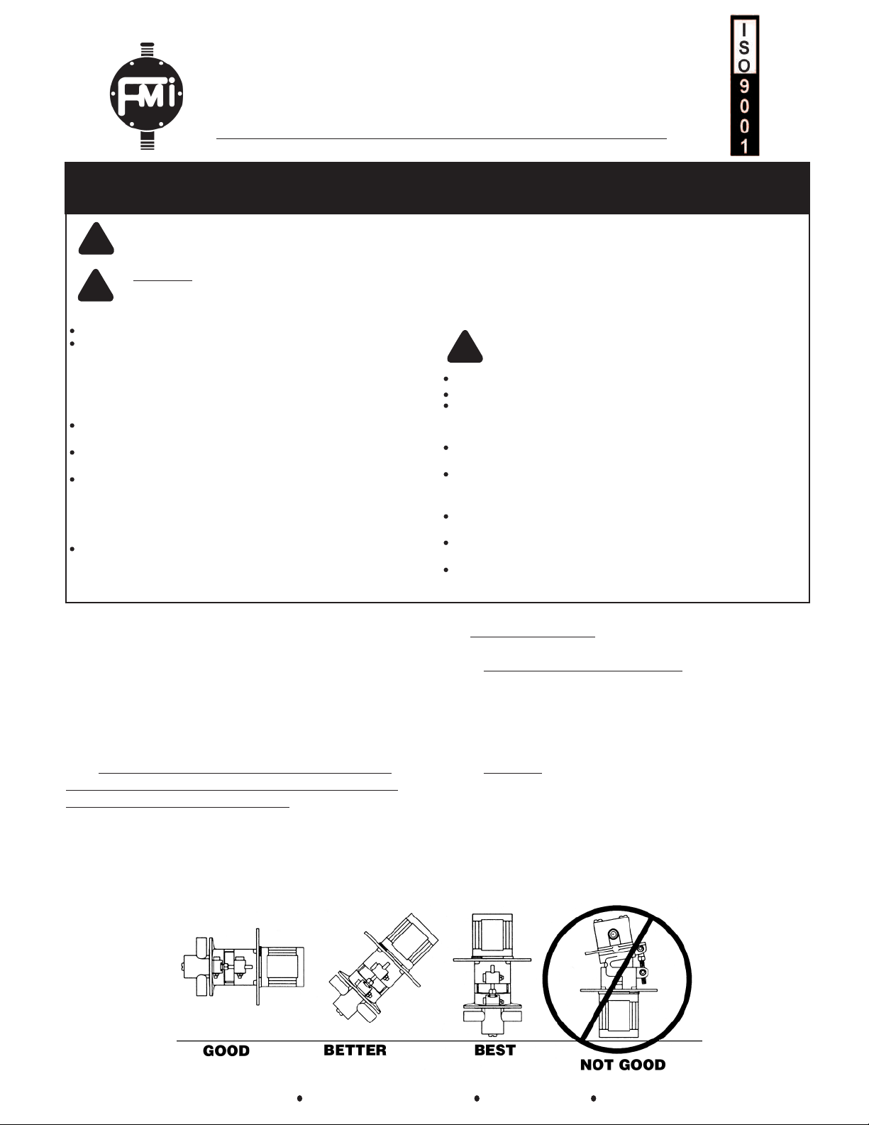
1.0 PUMP MOUNTING: For optimum pump performance it is recommended that your FMI pump
be mounted in a vertical position with the pump
head down in a 6:00 o'clock position and the motor
at 12:00 o'clock. This orientation will allow air bubbles that enter the pumping chamber to directly exit
through buoyancy assistance. Figure A
2.2 Fluidics:
Inlet (Suction) Tubing: To avoid cavitation use the
most resilient tubing possible with the largest
inside diameter (I.D.)
Outlet (Dispense) Tubing: For best dispense
performance use rigid Teflon tubing (to reduce
peristaltic action) with an equal or smaller I.D. than the
inlet (suction) tubing.
Figure A
www.fmipump.com pumps@fmipump.com 800-223-3388 516-922-6050
1
Page 2
IN-ST431-14
2.3 Step Motors:
MI ST pumps are supplied with a 17 or a 23
F
frame Motors.
For wiring diagram and detailed motor
specifications go to the literature section of our
ebsite at www.fluidmetering.com/literature.html
w
2.4 Rotational Sensor: FMI STH and
STQ standard pumps are supplied with an LED
rotational sensor. For wiring diagram and sensor
details see Figure G .
.6 Park Position:Preventive maintenance
2
steps in order to minimize the possibility of a
frozen pump or seize condition are as follows:
) Always completely flush out the pump with
a
water if it will be in an idle (non-operating mode)
for an extended period of time.
b) During shut down leave the pump’s fluid circuit
wet with flush water.
2.4.1 For sensor use with FMI SCST-01 Step
Motor Controller. See SCST-01 instructions.
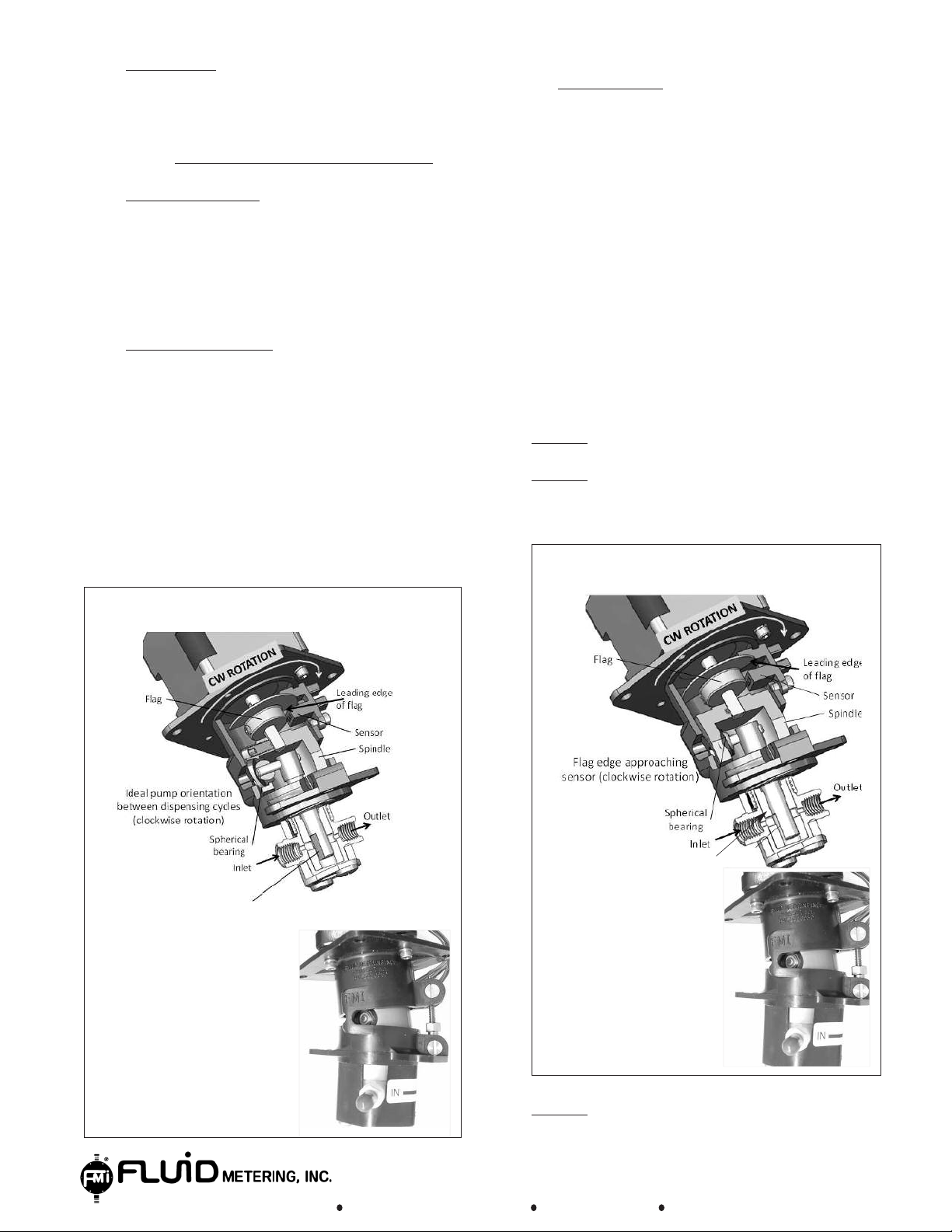
2.5 STH Pump Homing: Best dispensing
performance of the pump is obtained by proper set
up of the start/stop position of the piston relative
to the intake port of the pump housing.
Positioning of the piston flat so that it directly faces
the inlet port is termed “homing”.
The images below show the home position for a
pump which has been set up to turn clockwise.
In this case the inlet port is on the left.
If a particular application calls for the inlet port to
be on the right, the pump will be programmed to turn
counterclockwise and the figures bellow must be
reversed.
Home Position
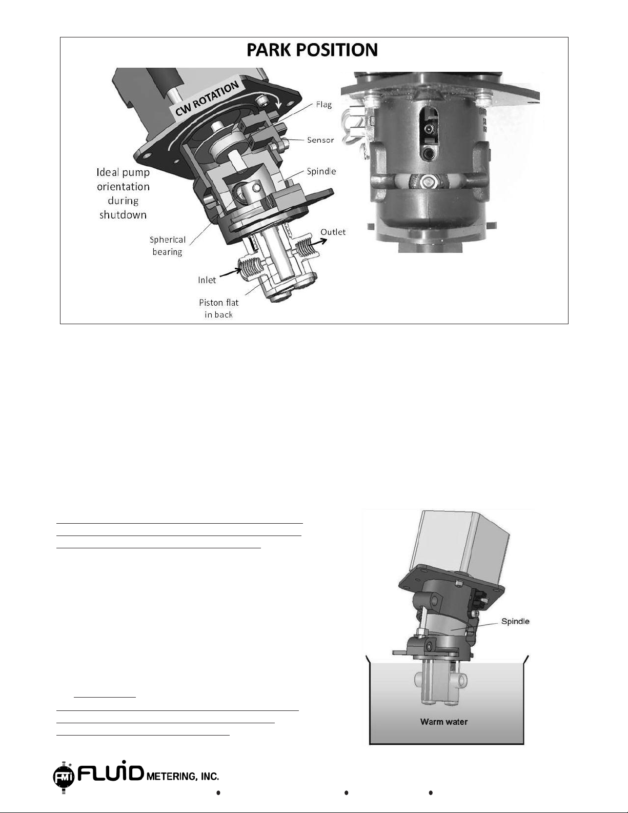
c) The piston position should extend all the way
towards the bottom of the liner. This is known as
the PARK position.
Correct programming of pump motion to achieve
the PARK position involves the following sequence
(assuming clockwise rotation for operation).
Step #1
Step #2 While monitoring sensor signal, instruct
motor to turn clockwise while looking for the
leading edge of the flag (see figure 2 below).
The FMI pump stops (any location).
Flag Edge Approaching Sensor
Figure 1
www.fmipump.com pumps@fmipump.com 800-223-3388 516-922-6050
Piston flat facing
intel port
Piston flat approaching
alignment with intel port
Figure 2
Step #3 Next rotate Counter Clockwise 90 Degrees
the pump is now PARKED.
2
Page 3
IN-ST431-14
The design of FMI Pumps is unique throughout the
world. Having no valves and only one moving part,
“the piston” makes this design very special. No valves
means that our ceramic pistons and cylinders must
be matched to extremely close fits so that stroke to
stroke accuracy is maintained.
This precision fit requires some general maintenance
rules.
When a pump is allowed to sit idle and dry out, these
dried precipitate can form in the piston/cylinder clearance and cause a pump seizure condition. Upon system power up, this seizure can result in either no flow
or at worst a broken piston. So we recommend the
above procedure.
We do not live in a perfect world and accidents do
happen. If your pump seizes try the following procedures: With the pump in an instrument:
1) Cycle the pump in a back and forth motion (clock-
wise and counter clockwise rotation) at a slow speed
in a high torque mode.
2) Start and stop the pump in an effort to free system.
a) Soak the top portion of the pump (PUMP HEAD
ONLY) in a warm water bath for at least 20 minutes.
Then place your index finger and thumb around the
spindle assembly (gold coupling) and gently try to
rotate the assembly back and forth in an attempt to
loosen up the piston.
CAUTION:
Do not force the assembly free if it is
severely frozen as this could result in piston
breakage or pump damage.
3) If pump head is accessible try turning the drive
spindle back and forth with your index finger and
thumb.
2.7 Maintenance
With the Pump/Drive Assembly removed from the
instrument but not disassembled (WILL NOT
REQUIRE PUMP RECALIBRATION):
www.fmipump.com pumps@fmipump.com 800-223-3388 516-922-6050
3
Page 4

IN-ST431-14
CAUTIONŽƌŝĞŶƚ,ϰϬϱůĞƚƚĞƌŝŶŐ
as shown
H435 Cap
Screws(2)
Tighten to
9 in-lbs torque
With the Pump/Drive Assembly removed from the
nstrument and the piston/cylinder group removed
i
(MAY REQUIRE PUMP RECALIBRATION):
b) If the pump is severely frozen then the piston/cylin-
er group must be removed from the pump. Remove
d
the (2) screws that secure the H435 Cap to the pump
base assembly and carefully remove (twist, tilt & pull)
the piston/cylinder group from the pump base assembly.
d) Reassemble the piston/cylinder into the pump
base assembly (use FMI Instructions H431) page # 8
section # 22 for more details relative to installing the
piston/cylinder assembly.
c) Soak the piston/cylinder group in warm water for
20 minutes minimum. For quickest results use an
ultrasonic bath. Then try to loosen up the assembly by
hand - gently rotating the piston back and forth until
free.
CAUTION:
Do not pull piston out of cylinder or force the
piston as breakage or seal damage will occur.
www.fmipump.com pumps@fmipump.com 800-223-3388 516-922-6050
e) Reinstall H435 Cylinder Cap and apply a suitable
thread lock to the screws (Loctite # 425) and secure
screws (torque to 9 in-lbs).
f) Rotate the assembly to assure it moves smooth
and free. (If not see note #1 below).
g) Check the pump for proper calibration (If out of
specification see note #1 below).
Note#1:
Please return complete pump/drive unit to the factory for rework and
recalibration
4
Page 5

IN-ST431-14
3.0 CALIBRATION AND TESTING
3.1 Flush the system: clean with alcohol
or other suitable cleaning/wetting agent
before using the hydraulics and pump for the
irst time. Prime pump with fluids to assure
f
system is free of air bubbles.
3.2 Place pump in the standard
"home"
position with the piston-flat perpendicular to
the inlet port.The inlet port will be on the left
when the motor rotates clockwise (see
Figure B for the STH pump and Figure C for
the STQ pump).
3.3 Check the pump's dispense volume by
cycling the pump for one complete 360°
revolution (one complete rotation). Dispense onto
an analytical pan balance and observe the volume.
See Figure D. Readjust as necessary.
REMARK: When dispensing water-like solutions
assume 1 ml = 1 gram. A correction factor will
be required for other fluids
Note:
Calibration is Factory set and Should not be
Changed.
Figure D
an Balance
p
Figure B
Figure C
www.fmipump.com pumps@fmipump.com 800-223-3388 516-922-6050
5
Page 6

IN-ST431-14
3.4 Dispense Volume Values for FMI STH/STQ
umps:
P
MODEL
ML/REV
MIN
STH00 0.002
S
TH0
.005
0
STH1 0.010
ML/REV
MAX
0.025
.050
0
0.100
STQ0 0.008 0.080
STQ1 0.032 0.320
STQ2 0.072
STQ3 0.128
0.720
1.280
NOTE: To assure the best performance set the
pump displacement volume as large as possible.
FMI pumps are calibrated at the factory to the
maximum value. Both STH and STQ pumps can
be factory adjusted down to as little as 10% of the
rated flow.
3.5 Adjusting Dispense Volumes:
To fine adjust dispense volumes rotate the stroke
length adjustment s crew using the appropriate hex
driver (see Required Tools on page 1). To increase
the flow, turn the screw counter-clockwise.
To decrease the flow, turn the screw clockwise
3) Splashing can usually be avoided by
odifying dispense tip to larger I.D.and/or
m
decreasing dispense speed.
4) Hanging drop at dispense tip can be avoided
y:
b
a) Use of rigid discharge tubing
b) Small dispense tip
c) Increasing speed
5) High viscosity dispensing requires:
a) Large suction tubing
b) Pressurizing suction reservoir
6) Bubbles in discharge
a) Suction fitting leak
b) Cavitation
7) Need Help? Call, fax, or email us… We can
help solve almost any fluid control problem.
3.8 SPECIAL MOTORS AND CONTROLLERS
FMI offers a complete variety of stepper motors
and stepper motor controllers from simple quick
start control to complex application specific
stepper motor control. Our standard step motor
controllers are:
SCST General Purpose Stepper Motor Control for
quick start control of FMI STH and STQ pumps.
CCW=Increase, CW=Decrease.
CAUTION: DO NOT LOOSEN THE HEX LOCK
NUT WHEN ADJUSTING THE STROKE RATE.
IT IS SET AT THE FACTORY AND SHOULD NOT
BE TAMPERED WITH. See Figure E
3.6 Lock setting:
Once the pump is calibrated apply a drop of
removable wicking thread lock between the lower
pivot pin and the adjustment screw threads.
See Figure E.
3.7 Dispensing Hints:
1) Speed - Optimum results for fluids 500 cps or
less is between 120-350 rpm.
2) Cavitation: Use the largest suction tubing you
can to avoid cavitation.
ICST Intelligent Stepper Motor Controller
which includes an embedded microprocessor
for custom programming of FMI stepper motor
pumps to meet specific application operations.
IDS 2000 Industrial Dispenser/Pump which
includes the SCST and FMI pump head integrally
mounted in a rugged stainless steel enclosure.
www.fmipump.com pumps@fmipump.com 800-223-3388 516-922-6050
6
Page 7

IN-ST431-14
Vcc
Vcc
* NOT SUPPLIED WITH OPTICAL SENSORS
See suggested Rd values table below.
NOTE:FOR ADDITIONAL REFERENCES SEE H431 AND Q431
Rotational Sensor
Absolute Maximum Rating (TA=25ºC Unless otherwise noted)
Supply voltage, V (not to exceed 3 sec.).......................18 V
Input diode power dissipation....................................100 mW (1)
Output power dissipation............................................200 mW (2)
Total device power dissipation....................................300 mW (3)
Voltage at output lead (open collector output)............35 V
Diode foreword D.C Current............................................40 mA
Diode reverse D.C Voltage.............................................2 V
Note:
1. Derate linearly 2.22mW / ºC above 25ºC
2. Derate linearly 4.44mW / ºC above 25ºC
3. Derate linearly 6.66mW / ºC above 25ºC
Figure E
4. The optical switches are terminated with 24 inches
of 26 A.W.G.,UL 1492 wire on each terminal.
Insulation colors and function are as follows:
Red-Anode, Black-Cathode, White-Vcc, Blue-Output,
Green-Ground
5. Normal application would be used with light source blocked,
simulated by I
6. All parameters tested using pulse techniques.
7. Minimum supply voltage is 4.5 VDC
www.fmipump.com pumps@fmipump.com 800-223-3388 516-922-6050
F=0mA
Suggested RD Values
Vcc (VDC) RD (Ω)
5 180
12 470
15 620
Figure F
7
 Loading...