


PDS-100
Programmable Dispensing System
INSTRUCTION MANUAL
OVERVIEW
The PDS-100 is a precision system capable of dispensing or pumping fluids ranging from 5 uL per dispense or 15 uL/min continuous (Single RH00LF) up to 1536 mL/min (Dual Q3) into pressures ranging from 10 psi (Q3) to 100 psi (RH). The PDS-100 offers single, dual (in phase, out of phase and independent) pump head control. PDS-100 offers RS485 communications, which allows the user to control the PDS-100 via a PC or PLC. Dry contact inputs offer an easy method to start and stop the pumps through the use of a simple switch. The PDS-100 also offers inputs which provide control of the dispense rate via a 0 – 10 VDC, 0 –5 VDC or 4–20 mA input.
A simple easy to use local keypad provides the user access to local control of the pump or pumps and a vivid display to provide user-friendly menus for ease of control.
Page 1 of 18
IN-PDS100-13A
11/1/13 HW
FEATURES:
“Set and Forget” approach 1-9999 dispenses (adjustable) Table top/wall mount
Universal power supply with standard IEC line cord
CSA/UL, CE, RoHS compliant
Learn mode/count to allow customer to command the PDS-100 to “remember” desired dispense cycles needed to fill to a desired volume.
Prime Mode Purge/Reverse Mode
Table-top Mounting: The system is configured for table top installation initially with rubber grommets slid into the mounting slots. Before moving on to configuring the control module, make sure that these rubber grommets are in place. There are no further installation steps for table top use.
Wall-Mounting: For wall mounting, it is necessary to remove the four rubber grommets from the control module before attempting to mount. Each unit must be mounted in the correct orientation; with the labels facing right side up, the control module will have the pumps at the bottom. Wall mounting may require an appropriate mounting board of at least 1/2”(12mm) thickness to straddle the studs of a typical plasterboard wall. See Figure 3.
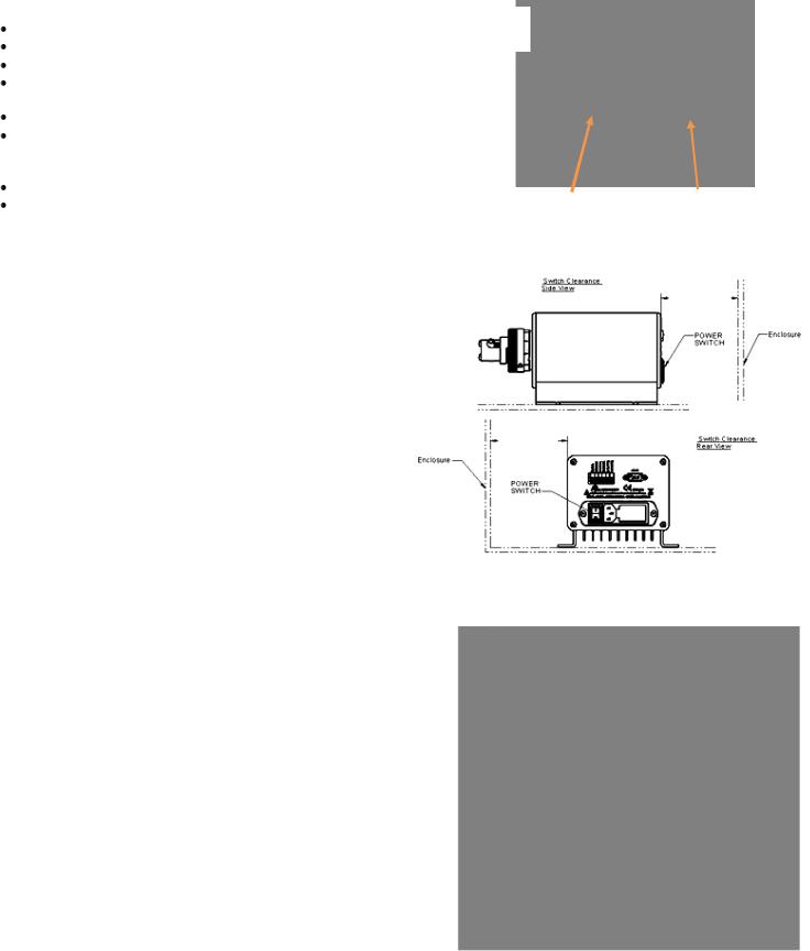
IMPORTANT When mounting PDS-100 in an enclosure it is important to maintain a minimum clearance to provide adequate space to reach the power switch. See figure 2.
Specifications
Supply Voltage: 100-240VAC +/- 10%, 50/60 Hz. Main Supply Current: 0.6 to 0.25 Amps. Fuses: T250V-1A (time lag), 5x20mm, 2 required.
Physical: Dimensions: 5" H x 6 1/4" W x 12" (max) D; Weight: 7 lbs
Environment: For indoor use only. Humidity: 80% max for temperatures up to 31°C, decreasing linearly to 50% relative humidity at 40°C. Pollution degree, 2. Operating temperatures range from 5ºC to 40ºC (41ºF to 104ºF).
Smooth Flow Operation
The PDS Smooth Flow product differs from the “Standard” PDS-100 in that the dual pumps have each been precisely calibrated to provide equal dispenses per revolution. The distinct difference found in the PDS Smooth Flow is in the method by which the pumps are driven. Proprietary programming provides a unique method of control in such a way as to provide a virtually pulseless output when both pumps are connected to a “Y” or “Tee” fitting.
Most of the controls and screens are the same for the Smooth Flow as shown in the previous pages with the exception that the pumps are not individually controllable. Instead the pumps are controlled as though they are one.
Menus, for the most part, are the same except while in dispense or continuous mode the word “Smooth” will appear at the top of the main screen. In addition you will see the word “Smooth Drive” when power is first applied to the unit.
Page 2 of 18
Power Switch |
Fuse Location |
Figure 1
PDS-100 Rear View
4.0”
MINIMUM REAR CLEARANCE REQUIRED
Switch Clearance
Rear View
4.0”
MINIMUM SIDE CLEARANCE REQUIRED
Figure 2
Minimum Power Switch Clearance
Figure 3
Required Mounting Pattern
IN-PDS100-13A
11/1/13 HW

Power Up Screens (two individually controlled pumps)
This is what will be seen on power up when the unit is configured for individually controlled pumps (factory default). For Single pump configured system use “Pump A” screens only.
PDS-100 |
Duo Drive |
Precision Dispenser |
Software |
Version |
Pumps
home
Duo Mode |
USE ARROWS TO SELECT |
A = Dispense |
B = Dispense |
PRESS ‘ENTER’ TO ADJUST |
Pump A
Pump B
Figure 4
Pump A & Pump B Location
Page 3 of 18
IN-PDS100-13A
11/1/13 HW
Setup Screens (two individually controlled pumps) Prime/Purge, Mode & Input Setup Screens
To select “Prime/Purge, Mode & Input Setup” screen wait for the pumps to home then press the up up/down arrow to select desired pump (A or B: see figure 4) and then press the Setup  button. The following screens are available. Pressing enter
  will go to each screen. Pressing the up
  or down
  arrow will select additional items.
***Factory default values shown***
Setup A = Prime |
‘ENTER’ FOR NEXT MENU |
Speed = 200 rpm |
Run = Start&Stop |
USE ARROWS TO SELECT |
Setup A = Purge |
‘ENTER’ FOR NEXT MENU |
Speed = 200 rpm |
Run = Start&Stop |
USE ARROWS TO SELECT |
Setup A = Mode |
‘ENTER’ FOR NEXT MENU |
Mode = Dispense |
Direction = CW |
USE ARROWS TO SELECT |
Setup = RS485 |
‘ENTER’ FOR NEXT MENU |
Interface = 2 Wire |
Device Addr. = 5 |
USE ARROWS TO SELECT |
Only appears if RS485 is selected for Control mode and/or Start mode on previous (Inputs) screen.
Setup A = Inputs |
‘ENTER’ FOR NEXT MENU |
Control = Keypad |
Start = Keypad |
USE ARROWS TO SELECT |
Page 4 of 18
IN-PDS100-13A
11/1/13 HW
Setup Screens (two individually controlled pumps) cont’d: Prime/Purge adjust and activation
Prime and Purge have the following available settings.
Setup A = Prime |
‘ENTER’ FOR NEXT MENU |
Speed = 200 rpm |
Run = Start&Stop |
USE ARROWS TO SELECT |
Setup A = Purge |
‘ENTER’ FOR NEXT MENU |
Speed = 200 rpm |
Run = Start&Stop |
USE ARROWS TO SELECT |
***Factory default values shown***
Speed (7 – 749 RPM for the STH & RH and 7 – 599 RPM for the STQ & STQP)
Run
1.Run = “Start&Stop”. Start prime/purge via keypad “Run” and stop prime/purge via “Stop”
2.Run = “Ext. Switch”. Start prime/purge via external switch. Pump will continue to prime/purge until switch is released. Switch A activates pump A and Switch B activates pump B.
3.Run – “Start&Hold”. Start prime/purge via keypad “Run”. Prime/purge will continue until the Run button is released.
To adjust either the speed or run method simply press the up  or down
  arrow keys to go to the desired item and then press the enter
  key to select. To set the speed press the up/down arrow keys
  until the desired speed is shown. Press enter
  key to save. To set the desired run method press the up/down
arrow keys until the desired run method is shown. Press enter  key to save. To start the Prime/Purge process use the device chosen (Keypad run button or external
switch). To exit setup press the setup  key and the motor(s) will automatically home or press the enter
  key to go to the next setup screen.
Page 5 of 18
IN-PDS100-13A
11/1/13 HW
Setup Screens (two individually controlled pumps) cont’d: Mode and direction adjust
Mode has the following available settings for direction.
***Factory default values shown***
Setup A = Mode |
‘ENTER’ FOR NEXT MENU |
Mode = Dispense |
Direction = CW |
USE ARROWS TO SELECT |
Mode |
o Continuous (pump will run until a Stop command is given).
oDispense (pump will run until a Stop command is given or the programmed dispenses is reached)
Direction o CW
o CCW
NOTE: When operating in dual pump mode, the direction will change both pumps. Independent direction control is not available.
To adjust either the mode or direction simply press the up  or down
  arrow keys to go to the desired item and then press the enter
  key to select. To set the mode press the up/down
  arrow keys until the desired mode is shown. Press the enter
  key to save. To set the desired direction press the up/down
 arrow keys until the desired direction is shown. Press the enter
  key to save. To exit setup press the setup
  key and the motor(s) will automatically home or press the enter
 key to go to the next setup screen.
Page 6 of 18
IN-PDS100-13A
11/1/13 HW
 Loading...