

Page 1
INSTRUCTIONS
MODELS GPD, SPD PNEUMATIC DRIVES
FMI Pneumatic Pump Drives are similar in design to the standard FMI “Q” pump; please review the Q431
Instruction and Parts Identification Sheet.
OPERATION:
1. Follow all safety codes during installation of your FMI Pneumatic Drive.
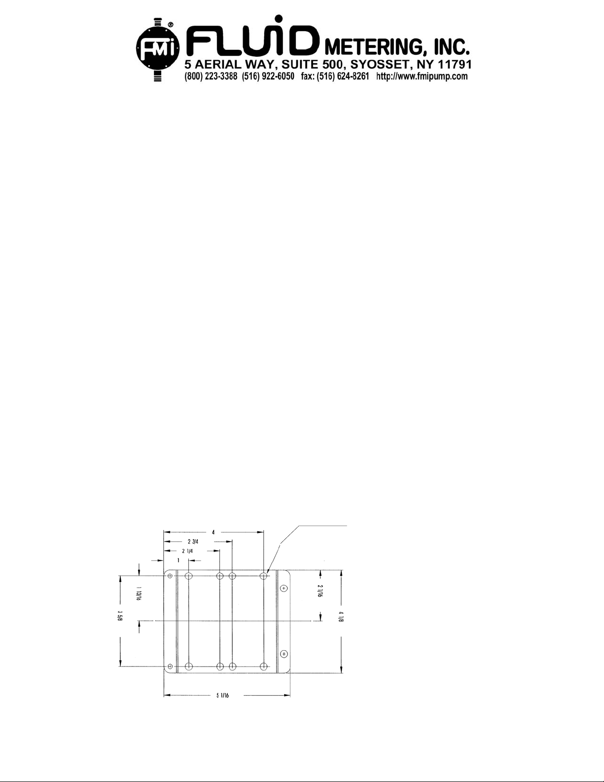
2. Your Standard Pneumatic Drive Pump (SPD) or Gear Pneumatic Drive (GPD) must be rigidly
mounted using the four 9/32 Dia. holes in bracket Q648, see fig. 1. (Drives can be mounted
either horizontally on table or lab bench, or vertically on wall with pump head facing down).
3. Important. For proper rotation (clockwise) air must enter right port (use 1/8” NPT). All air
Lines should be clean and free of foreign matter. Install standard filter, regulator and
lubricator as close as possible to motor inlet port. The lubricant should feed oil at a rate of
one drop for every 50-75 CFM of air going through motor.
4. Air Requirement: SPD 9-10 CFM at 40 psi GPD 14-16 CFM at 40 psi. If reduced noise is
desired exhaust air can be run to some remote location away from work area using flexible
tubing, all lines should have minimal amount of bends, elbows, tees, etc.
5. Pump flow rates may be varied by simply regulating air flow to the motor. A typical speed
regulation system is composed of two pressure regulators, one on inlet line, and one on
outlet line.
MAINTENANCE:
1. Lubrication of Standard Pneumatic Drive: use detergent SAE #10 automotive engine oil.
2. Lubrication of Gear Pneumatic Drive: use a 300 SUS @ 100º F turbine quality lubricant. For
horizontal operation remove the two hole plugs, (see exploded view GPD on reverse side). Add
oil to one hole until second hole overflows. For vertical operation fill to overflow point of upper most hole.
IN PD431-03
PRINTED IN U.S.A.
9/32 DIA. MOUNTING
HOLES (4 PLACES)
Fig. 1
Page 2
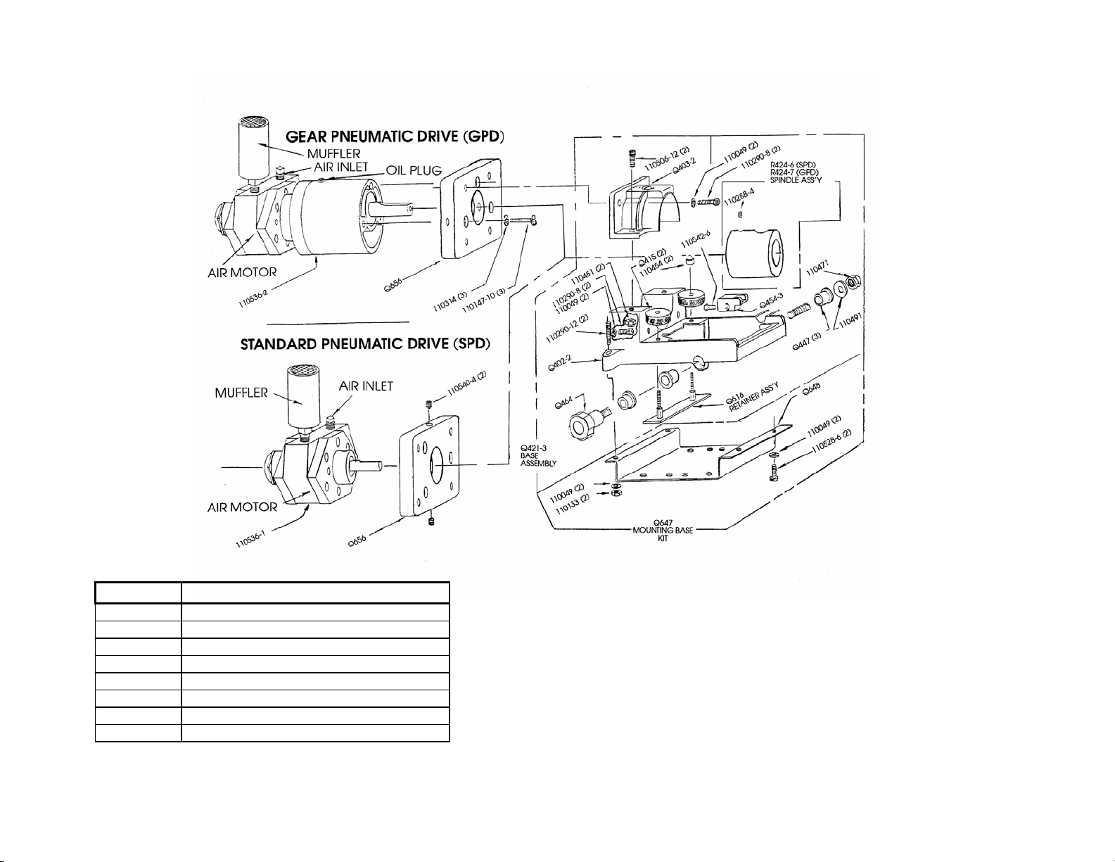
PARTS IDENTIFICATION MODELS GPD, SPD
PART NO. DESCRIPTION
Q656 MOUNTING PLATE, AIR MOTOR
R404-7 SPINDLE, FOR R424-7 ASS'Y
R424-7 SPINDLE ASS'Y FOR GPD
110314 WASHER #10 INT. LOCK
110147-12 SCREW #10-32x3/4 LG PAN HD
110540-4 SET SCREW 1/4-28x1/4 LG CUP POINT
110536-1 AIR-MOTOR (STANDARD) SPD
110536-2 AIR-MOTOR (GEAR) GPD
IN PD431-03
PRINTED IN U.S.A.
Please refer to “Q” Pump Line Instructions Q431 for complete descriptions and prices on all parts
Page 3
r
(
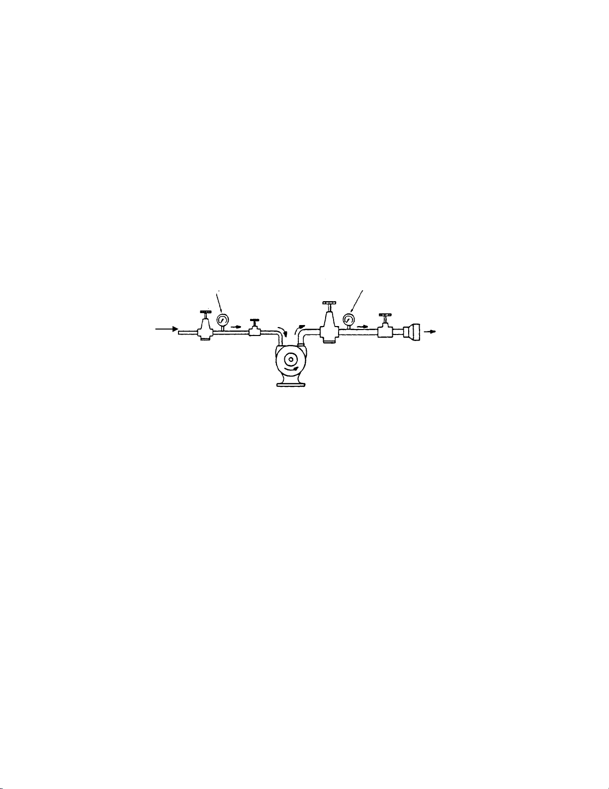
Variable speed Control.
The best speed-regulation system is composed of two pressure regulators and two valves connected as
shown in the sketch.
When the load decreases, the motor's speed increases. This increased speed causes more air to flow. But
because P5 is constant and the flow through the orifice is also constant, P4 must increase. P3 increases
until the pressure differential (P3-P4) across the motor supplies only enough torque to maintain speed. Any
adjustment of R1 will, of course, affect P2 and P3.
The startup procedure is as follows:
• Close valve A; turn the larger regulator's (R2) adjustment all the way in and open valve B all the way.
• Turn the pressure adjustment on the small pressure regulator (R1) until P2 = 70 psi (or slightly more).
0/100 psi pressure gauge
R1
Plant air line
pressure
P1
R1 =REGULATOR SIZED FOR ALL MOTORS
INTAKE PORT
R2 = REGULATOR SIZED ONE SIZE LARGER
THAN R1
P1 P2 P3 P4 P5 = IN-LINE PRESSURES
P2
Valve
A
P
P3
4
Air Motor
0/30 psi pressure gauge
R2
Valve
B
P
5
Muffler
Low-restriction)
• Slowly open valve A until the conveyor is running at the desired speed with full load. If adequate speed
regulation is achieved with just these components, the large regulator and valve B are not needed and
may be removed. If not, go on to the next step.
• Adjust valve B so that P4 = 5 psig; readjust valves A and B so that a speed slightly greater than that de-
sired is obtained.
• Adjust the large regulator until a slight drop in air motor speed is observed. The pressure across the ai
motor now will be automatically regulated to minimize the effect of load on the set speed.
IN PD431-03
PRINTED IN U.S.A.
 Loading...