

Page 1
"SCST-01" STEP MOTOR
CONTROL KIT
http://www.fmipump.com
OPERATION INSTRUCTIONS
New FMI Step Motor Control Kit “SCST-01”
Congratulations! Your FMI Step Motor Control Kit SCST-01 is a complete control
package designed specifically for FMI pumps with step motors. It’s small in size but big
in performance and provides a quick method to run your pump today.
Quick Start Instructions
Your controller is initially set to provide 320 strokes/minute or 150 strokes/minute.
Dispense and other speed settings are easily set by following the detailed instructions
on the following pages.
1. Connect harness J1 & J2 to appropriate connectors on board. The black and white
wires from J1 connect to the power supply. White (or black with white lettering) is the
positive lead while solid black is negative.
*Connect DIP Switch Assembly to Header J3 (Pin 1 to red stripe)
DO NOT TURN POWER ON
2. Connect motor wires to terminal block J1 according to the following chart:
Table1.
Screw Terminal
Color
Motor Lead Color for Standard
STRH/STH/STQ/SQ pumps
Motor Phase Motor P/N 110746
(NEMA 23 Frame)
Motor P/N 110745
(NEMA 17 Frame)
STRH/STH/STQ/SQ
Duplex
Motor P/N 300615
(NEMA 23Frame)
Yellow A Yellow and Black Yellow Orange & White w/Black
Stripe
Red A Red and White Red Black & White w/Orange
Stripe
Brown B Blue and Orange Orange Yellow & White w/Red Stripe
Orange B Green and Brown Blue Red & White w/Yellow
Stripe
3. Connect pump sensor leads to J2 according to color i.e. Red to Red, etc.
4. Turn on power and pump will start running at factory setting. Note: See 4.1 page 6.
*Basic Boards use jumper pin connector shunts instead of DIP switch.
1.0 Description
IN-SCST-01-10 1
Page 2
"SCST-01" STEP MOTOR
http://www.fmipump.com
OPERATION INSTRUCTIONS
The SCST-01 is a self-contained step motor controller specifically designed for use with
Fluid Metering pumps. It contains its own step drivers and can be set to several run
modes utilizing either internal or external controls.
1.1 Features
• Pre-set Run Modes
• Multiple Control Methods: PLC, Relay, 0-5 VDC, or Manually by shunt
• Dispense, Run
• Sensor Enable/Disable
• Switchable Forward/Reverse of Motor Direction
2.0 Run Modes
The SCST-01 step motor controller can be used to drive any FMI stepper driven (STH,
STQ) pumps in any of the following modes.
2.1 Continuous (Constant Run) Mode
Your Kit comes factory set for 320 or 150 spm (strokes per minute). Speed is easily
adjustable using shunt connectors on Speed Header J3 (fig. 1) or DIP Switch Assembly.
Speed is adjustable using Pins (Switch) 1-7 and binary addition according to the
following chart and diagram or by 0-5 VDC input (Section 2.4).
Figure 1
Switch
/ Pin Speed
SPEED HEADER - J3
Dispense Pins/ Switches
Speed or rpm Pins/ Switches
CONTROL KIT
1 =
2 =
3 =
4 =
5 =
6 =
7 =
10 rpm
20 rpm
40 rpm
80 rpm
160 rpm
320 rpm
640 rpm
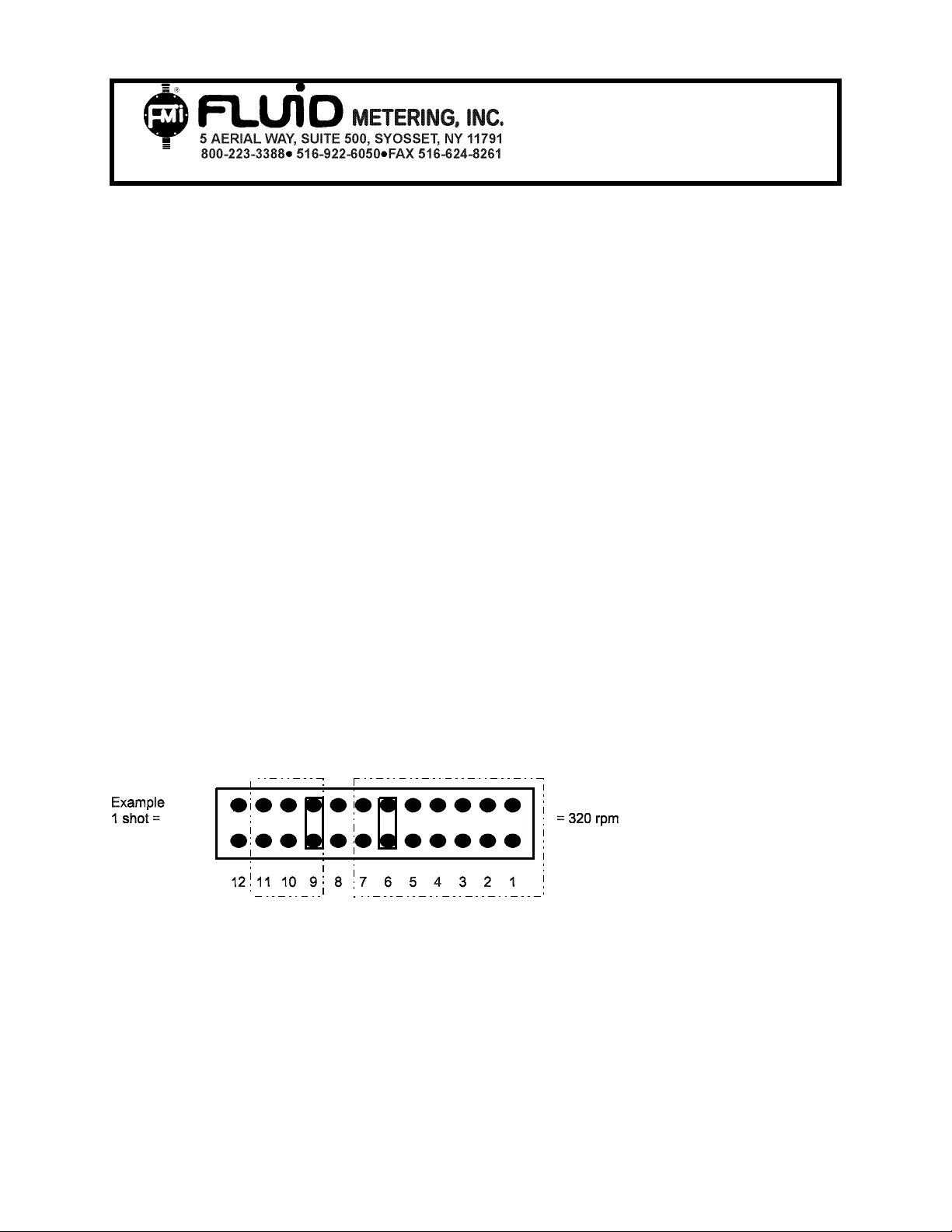
2.2 Dispense Mode
The system will allow you to dispense from 1 to 7 shots per signal (momentary switch
closure on J2). The number of shots per signal is set by shunting pin/Switches sets 911 on Header J3.
Pin/Switch No.= # of shots Example
IN-SCST-01-10 2
Page 3

"SCST-01" STEP MOTOR
http://www.fmipump.com
OPERATION INSTRUCTIONS
Pin 9 = 1 Pin 9 + Pin 11 = 1 + 4 = 5 shots
Pin 10 = 2
Pin 11= 4
2.21 Actuation For Dispense
Dispense Actuation is handled by Pins 3 & 4 on the J2 Terminal Block by providing a
momentary contact (switch closure, PLC, Relay, Mechanical Timer) of the 2 yellow
wires. The minimum closure time that this input can see is 30 milliseconds (0.030 sec).
DO NOT APPLY ANY VOLTAGE to this input!
2.3 Timed/Count Dispense (Pin Shunt use only)
The pump will begin dispensing until both pins of pin set 9 on J3 are shorted together.
This will cause the pump to stop. Pin set 9 can be shorted by using any counter or
timer that can control a SPST type relay or switch closure. External counters can tap
pin 8 on J2 to sense the count pulse.
Typical wiring is as follow: With FMI Motors
CONTROL KIT
OPTICALLY ISOLATED
2
E
C
2N3904
B
1
4N35
6
5
4
J2 PIN 7
J2 PIN 8
DIRECTLY COUPLED
E
C
0.01mF
2N2222
* R
*R=10 k (for reference only, your specific
application "value" may need adjusting.
B
[SIGNAL IN]
[GROUND]
5 V DC
(J2 PIN 9)
[GROUND]
(J2 PIN 7)
(J2 PIN 8)
150 OHM
1 K OHM
2.4 External Control 0-5 VDC - Voltage Following Input
In order for the stepper controller board to recognize and accept a 0-5 VDC control input
all shunts on pins 1-7 (header J3) must be removed or Switched off. The board will not
respond to a voltage input if any of the speed select pins have a shunt across them.
Once the shunts on all pins are removed, a DC voltage signal may be applied to header
J2 pins 1 and 2 and a variation of that voltage will linearly vary the motor speed.
Maximum speed using a 0-5 VDC input signal is limited to 1200 rpm, depending on the
application. For duplex motor P/N 300615, the max speed is 150rpm.
3.0 Input Headers
The SCST-01 step motor controller has several different input/output header sections
for control and interface with the stepper motor. A diagram showing the placement of
these headers can be found in Figure 2.
A single 24VDC power supply delivering 1.25A (min) of current is required for
driving any of the standard Fluid Metering step motors (inputs 1 and 2 on Header
J1).
IN-SCST-01-10 3
Page 4

"SCST-01" STEP MOTOR
http://www.fmipump.com
OPERATION INSTRUCTIONS
3.1 POWER Header - J1
The POWER header section (J1) is used for input power and output to the stepper
motor phases. This is a 0.156” pitch 6 pin header connector which has the following
pinout:
Pin #
1. Power supply minus lead (V-) connection.
2. Power supply plus lead (V+) connection.
3. Connection to phase B of the stepper motor.
4. Connection to phase⎯B (B bar) of the stepper motor.
5. Connection to phase A of the stepper motor.
6. Connection to phase⎯A (A bar) of the stepper motor.
3.2 CONTROL Header - J2
The CONTROL header section (J2) is used for optical sensor connections, 0-5 VDC
controls and dispense controls. This is a 0.100” pitch 9 pin header connector. The
pinout for this header is as follows:
Pin #
1. 0-5 VDC Common
2. 0-5 VDC Signal Input
3. Start Pulse Common
4.* Start Pulse Signal Input (for dispense, controlled by momentary switch to
ground)*
Hall Effect sensor Opto Sensor 110569 Opto Sensor 300696
5. Emitter Cathode (black)
6.
7. Detector Ground
(green)
Emitter Anode (red)
Detector Ground (green)
/ Power Supply Ground
/ Power Supply Ground
8. Detector Signal (blue) Detector Signal (blue) Detector Signal (white)
9. Power +5 VDC (white) Power +5 VDC (white) Power +5 VDC (red)
NOTE: The colors listed for sensor leads are for the standard sensors supplied with FMI
pumps. Other sensors may have other lead color configurations.
*Note: DO NOT APPLY ANY VOLTAGE TO THIS INPUT!
CONTROL KIT
Detector Ground (black)
/ Power Supply
Ground
IN-SCST-01-10 4
Page 5

"SCST-01" STEP MOTOR
http://www.fmipump.com
OPERATION INSTRUCTIONS
3.3 SPEED Header - J3
The SPEED header section (J3) is used for speed settings, number of dispense
settings, and switching between stall detect (sensor) and non-sensor mode. This is a
dual row 0.100” pin header. Functions are actuated by means of connecting pins using
industry standard shunts or by DIP Switch Assembly. This header contains the controls
for speed settings, stall detect enable, and number of dispenses. The pinout for this
connector is as follows:
1. Speed - 10 rpm
2. Speed - 20 rpm
3. Speed - 40 rpm
4. Speed - 80 rpm
5. Speed - 160 rpm
6. Speed - 320 rpm
7. Speed - 640 rpm
8. Sensor detect on/off - The default (no shunt) is sensor enabled ( See page 1
item#4).
9. Dispense - 1 dispense
10. Dispense - 2 dispenses
11. Dispense - 4 dispenses
12. CW/CCW - The default (No Shunt) CW Rotation
13. Not Used.
These pins are set up as a binary system. This means that multiple pins shunted will
add their values together. For example, to set the motor to run at 500 rpm you must
shunt pin pairs Switches 6, 5, and 2 (320+160+20=500 rpm). The shunts can give a
maximum speed of 1270 rpm and 7 dispenses. (see page H1 item # 4) The controller
will run at constant speed until one of the dispense setting pairs are shunted.
The motor will then home itself to the proper starting point and begin the desired
number of dispenses upon connection of the Start Pulse Signal and the Start Pulse
Common pins (Header J2, pins 3 and 4) by means of a momentary switch.
3.4 Header – J4
This Header is for internal FMI use only. It has no function to control the Driver Board.
CONTROL KIT
IN-SCST-01-10 5
Page 6

"SCST-01" STEP MOTOR
http://www.fmipump.com
OPERATION INSTRUCTIONS
4.0 Features
4.1 Trim Pot
Factory set at (approx.) For motors P/N 110746, 300615 the trim pot is factory set at
1.75 amp/phase. The trimming potentiometer (see Figure 2 for approximate location) is
used to limit the amount of current used by the controller in driving the stepper motor.
Turning the potentiometer clockwise will provide more current to the motor, while turning
it counter-clockwise will reduce the current supplied.
Figure 2
CONTROL KIT
PHASE⎯A6
PHASE A 5
PHASE⎯B4
PHASE B 3
+ SUPPLY LEAD 2
−
SUPPLY LEAD 1
SENSOR POWER 9
SENSOR SIGNAL 8
SENSOR GROUND 7
SENSOR ANODE 6
SENSOR CATHODE 5
START SIGNAL 4
START COMMON 3
0-5 VDC INPUT 2
0-5 VDC COMMON 1
SPEED HEADER - J3
TRIM POT
Dispense Pins
Speed or rpm Pins
IMPORTANT
!
Additional heat sinking may be required when operating above 2.5 amps per phase.
Contact factory for additional information.
IN-SCST-01-10 6
Page 7

"SCST-01" STEP MOTOR
CONTROL KIT
http://www.fmipump.com
USE AMP METER 5 AMP FULL SCALE **
OPERATION INSTRUCTIONS
A
-
+
A
A
A
-
+
A
A
Nema 23 Frame (2.2 inch square)
FMI Part Number 110746
** Adjust motor current trim pot as required.
Do not exceed maximum motor rated current
of 3.5 Amps per phase.
Higher speed values can be achieved with
a 30 VDC 4 amp minimum power supply.
Pin # J1----POWER HEADER
Screw Terminal
Color
Yellow
6
5
4
3
B
B
Red
Brown
Orange
Motor
Phase
A
A
B
B
Nema 23 Frame (2.2 inch square)
FMI Part Number 300615
(DUPLEX DRIVE MAX SPEED 150 RPM)
** Adjust motor current trim pot as required.
Do not exceed maximum motor rated current
of 3.5 Amps per phase.
Higher speed values can be achieved with
a 30 VDC 4 amp minimum power supply.
Pin # J1----POWER HEADER
Screw Terminal
6
5
4
3
Color
Yellow
Red
Brown
Orange
Motor
Phase
A
A
B
B
Motor Lead
Connection
Yellow-Black
Red-White
Blue-Orange
Green-Brown
Motor Lead
Connection
ORG-WHT/BLK
BLK-WHT/ORG
YEL-WHT/RED
RED-WHT/YEL
B
B
A
-
+
A
A
Nema 17 Frame (1.7 inch square)
FMI Part Number 110745
** Adjust motor current trim pot as required.
Do not exceed maximum motor rated current
of 1.2 Amps per phase.
Pin # J1----POWER HEADER
Screw Terminal
Color
Yellow
6
5
4
3
B
B
Red
Brown
Orange
NOTE: Black no connection
White no connection
Motor
Phase
A
A
B
B
Motor Lead
Connection
Yellow
Red
Orange
Blue
IN-SCST-01-10 7
 Loading...