

Page 1
IN-QC72/QC216-04
MOTOR ASSY
SE
1
INSTRUCTIONS
& PARTS LIST
DISPENSER
INSTALLATION & OPERATING TIPS
1. OPERATION - The QC has three
switches to control its functions:
a) An air-activated hand/foot switch
at the end of a 6’ long hose. This
switch starts and stops each operating cycle. It can be operated by hand,
foot, or other remote pressure means.
b) A mode switch in the up or dispense position. This switch permits
only one dispense or aspirate per
squeeze of the hand/foot switch. The
pump will make a complete uninterrupted dispense cycle once hand/
foot switch is squeezed and held and
will reset itself when released. The
down or pump position permits the
unit to operate continuously as a
pump. The hand/foot switch is inoperable in this mode.
c) A direction switch controls the
direction of fluid flow through the
pump head when the hand/foot switch
is squeezed, i.e., pushing the direction switch to the FWD or up position
will cause flow in that direction when
the hand/foot switch is squeezed.
Push switch down to the REV posi-
tion to reverse flow direction.* A center
“OFF” position on this switch provides
system off facility.
*Preferred pumping and dispensing direction
is from left to right when facing the pump head.
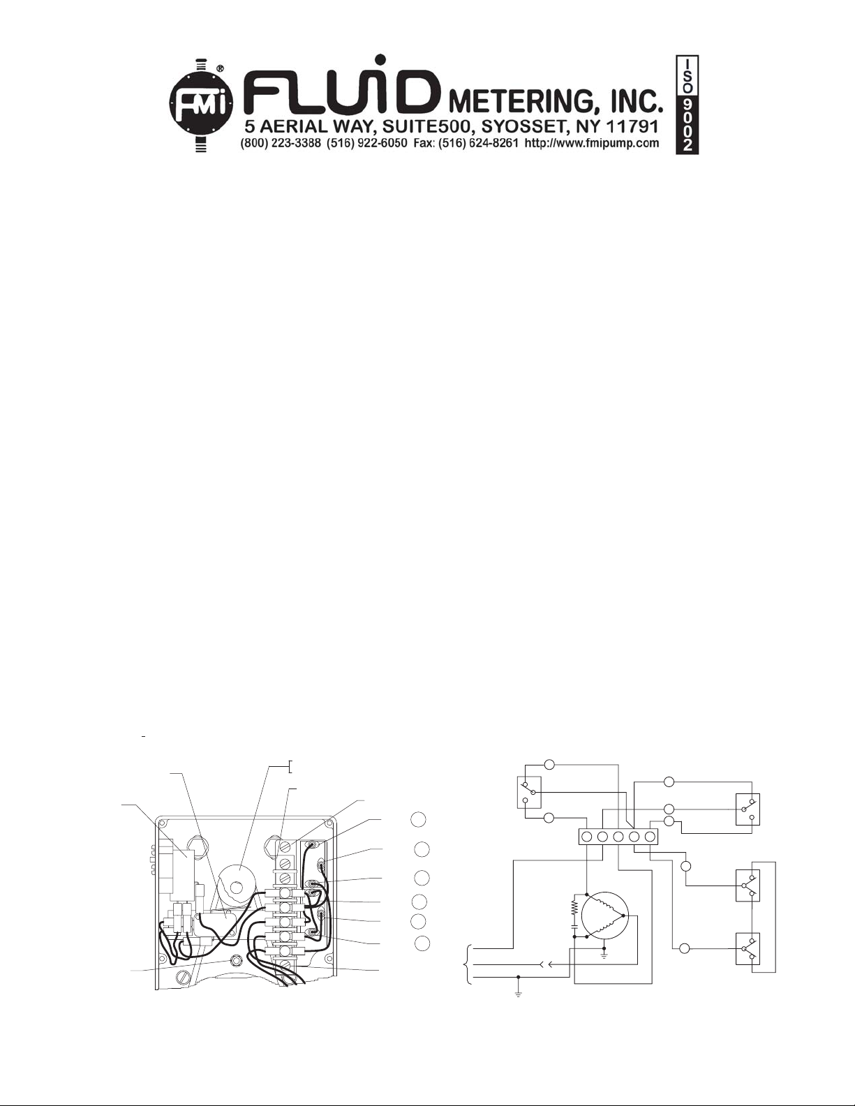
2. CAM ADJUSTMENT - Your QC
Dispenser hand/foot switch relates directly to a Cam Q502 actuated Limit
Switch Assembly Q501. This is timed
to the piston suction position. To adjust, loosen mounting Screws 11047710 on Terminal Strip 110476. Adjust
Limit Switch Assembly to Cam Q502
so that you get 2 clicks per revolution.
Tighten screws 110477-10 on Terminal Strip.
3. CALIBRATION - Hook-up inlet and
outlet tubing, set mode switch in down
(PUMP) position and clear the pump
of bubbles (see FMI Q431 instructions
and Parts Identification sheet, Sec.
12).
Calibration for specific shot volumes is
rather straightforward.
MODEL QC72/ QC216
a) Determine volume required per
shot.
b) Estimate approximate percentage
of maximum per shot flow for your
particular pump head, i.e., -3 or 1/2”
piston pump heads at 100% = 1.28
ml per shot, -2 or 3/8” piston pump
heads at 100% = 0.72 ml per shot, 1 or 1/4” piston pump heads at 100%
= 0.32 ml per shot and -0 or 1/8”
piston pumps at 100% = 0.08 ml per
shot.
c) When approximate setting is
made, pump 20 shots into a calibrated receiver (pipette, burette,
graduate), and divide the measured
volume by 20 to find the exact per
shot volume. If your volume is too
low, increase stroke volume by turning the STROKE LENGTH ADJUSTMENT KNOB Q464 counterclockwise. If too high, decrease by turning
clockwise. Repeat calibration check
as you fine-tune to your requirements.
110529
10490-8
Q501
Q502
110671-4
110476
Q463
110392
DIRECTION
SWITCH
REV
OFF
FWD
(BLK) 3
BLK
(RED) 4
RED
GRN
WHT
WHT
N.O.
RED
A
B
B
WHT
ORG
A
WHT
Fig. 1Fig. 1
Fig. 1
Fig. 1Fig. 1
5
RED
RED
4
BLK
BLK
3
BLK
BRN
2
GRN
RED
1
(GRN) 1
(RED) 4
(BLK) 2
(WHT) 5
110477-10
INPUT
BRN
LT BLUE
GRN-YEL
GRN
Q644 BLK
3
Q642 RED
Q639 GRN
1
110476
R1
C1
(RED)
1
WHT
RED
(BLK)
Q468-_
Fig. 2Fig. 2
Fig. 2
Fig. 2Fig. 2
32 4 5
BLK
4
2
5
4
Q637 (WHT)
LIMIT SWITCH
5
Q643 RED
Q638 BLK
Q641 WHT
110529
AIR SWITCH
Q640 (RED)
COM
Q501
ASSY
COM
PUMP
110433
MODE
SWITCH
DISPEN
N.O.
N.C.
Q635
(ORG)
N.O.
N.C.
Q636 (WHT)
Page 2
IN-QC72/QC216-04
(2)
90-14(2)
1
1
P
T
R
A
A
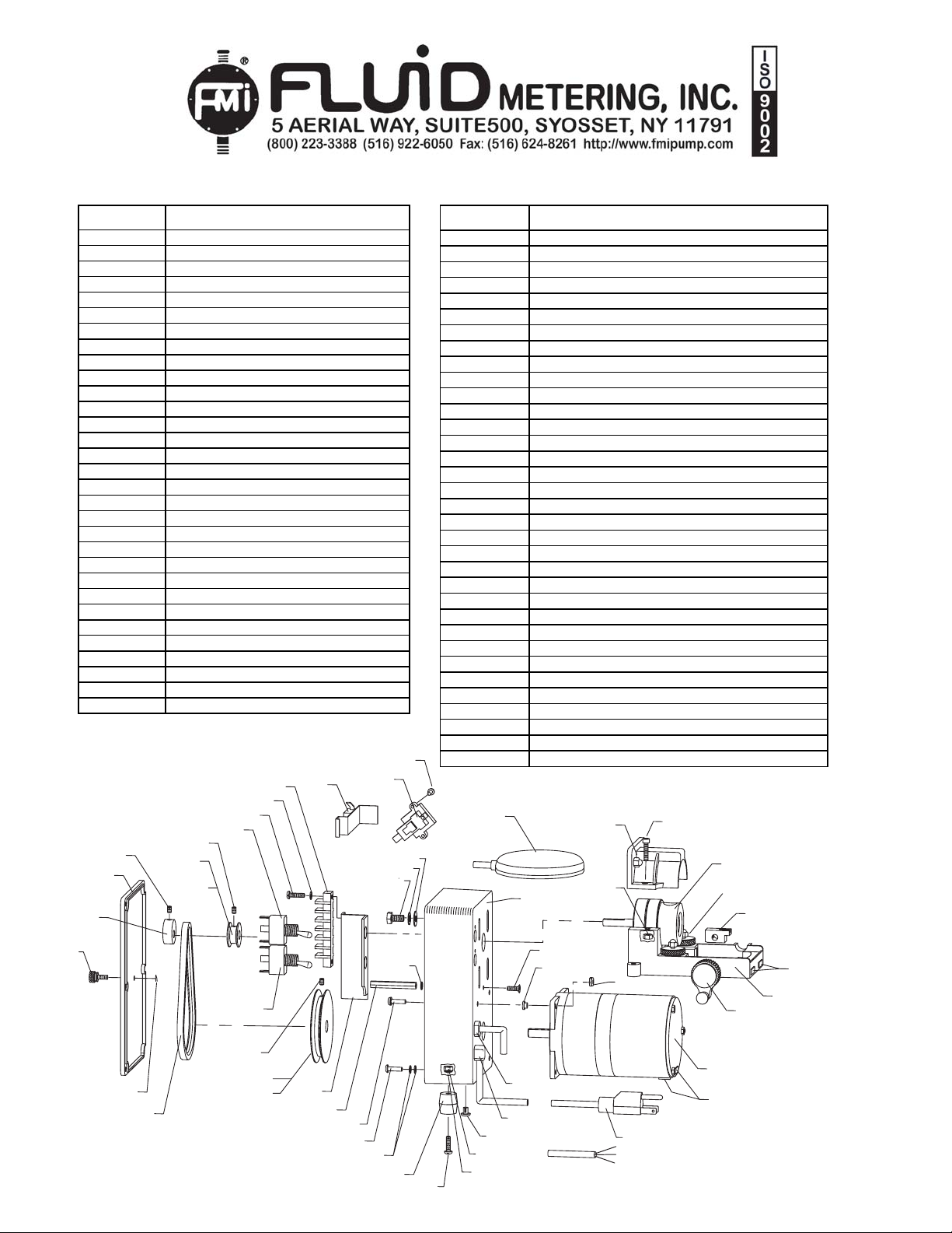
QC72/QC216 - PARTS PRICE LIST
PARTS NO. DESCRIPTION
Q424 SPINDLE ASSEMBLY
Q442-3 CASE ASSEMBLY
Q443-1 COV ER ASSEMBLY
Q448-2 PULLEY , 2” DIA., .313 I.D. 72S.PM
Q448-4 PULLEY , 2” DIA., .376 I.D. 72S.PM
Q448-1 PULLEY , 1” DIA., .313 I.D. 216 SPM
Q448-5 PULLEY , 3” DIA., .376 I.D. 216 SPM
Q454-3 FOLLOWER, FLOW CONTROL
Q456-1 POWER CORD ASSEMBLY 110 V OLT
Q456-2 POWER CORD ASSEMBLY 320 V OLT
Q463 BRACKET
Q468-1 MOTOR ASSEMBLY QC115 V AC 60HZ
Q468-2 MOTOR ASSEMBLY QC 230 V AC 50HZ
Q501 LIMIT SWITCH ASSEMBLY
Q502 CAM
Q616 RETAINER ASSEMBLY
Q635 JUMPER ASS’Y ORANGE (2-3/4” LG)
Q636 JUMPER ASS’Y WHITE ( 2-3/4” LG)
Q637 JUMPER ASS’Y WHITE ( 3-5/8” LG)
Q638 JUMPER ASS’Y BLA CK (2- 1/2” LG)
Q639 JUMPER ASS’Y GREEN (3-1/2” LG)
Q640 JUMPER ASS’Y RED ( 3-1/ 2 ” LG)
Q641 JUMPER ASS’Y WHITE ( 2-1/2” LG)
Q642 JUMPER ASS’Y RED (4” LG)
Q643 JUMPER ASS’Y RED ( 2-3/ 4 ” LG)
Q644 JUMPER ASS’Y BLA CK (3” LG)
110049 WASHER #8 INT. LOCK
110126 1/4 ID X 1/2 OD WASHER
110132-10 SCREW 8-32 X 5/8 PAN HEAD
110133 #8-32 X 11/32 D HEX NUT
110258 FOOT RUBBER
Fig. 3Fig. 3
Fig. 3
Fig. 3Fig. 3
Q501
110650-8(4)
110671-4
Q443-1
Q502
110288-2
Q448-1
(QC216)
Q448-2
110476
110479(2)
110477-10(2)
110392
(QC72)
10407(2)
110529
110126
110511(4)
PARTS NO. DESCRIPTION
110288-2 SET SCREW, #8-32 X 1/8” LONG
110288-4 SET SCREW, #8-32 X 1/4” LONG
110290-14 SCREW 8-32 X 7/8 SHD CA P
110295-1 LOCK NUT, #8-32
110388-1 BUSHING STRAIN RELIEF STR.
110388 BUSHING STRAIN RELIEF ANG.
110392 SWITCH-TOGGLE ( ON-OFF)
110405 REST PAD
110407 SCREW, SHEET METAL
110433 SWITCH-TOGGLE ( ON-OFF)
110436 EXTERNAL HAIR COTTER PIN
110437 THUMB SCREW, #8-32 X 13/32” LONG
110476 TERMINAL STRI
110477-10 SCREW, #6- 32 X 5/8” LG. PAN HEAD
110479 LOCK WASHER, #6 INT. TOOTH
110489-30 STANDOFF, #8-32 X 1-7/8” LONG
110490-8 SCREW, #8-32 X 1/2” 82° FLAT HEAD
110492 #1/4-20 NYLON CA P NU
110502 NYLON PLUG
110505 NYLON WA SHE
110506-12 SHC SCREW #10-32 X 3/4”
110511 WASHER, 1/4” INT. LOCK
110512 WASHER, 1/4” EXT. LOCK
110529
110531
110542-6 8-32 X 3/8” HD NYLON
110650-8 SCREW HEX HD 1/4-20 X 1/2” LONG
110655-12 SCREW PHP 8-32 X 3/4"
110671-4 SET SCREW,CP 8-32 X 1/4" DRI-LOC
110674 BELT “V”
110863-10 SCREW PHP 8-32 X 5/8" SEMS FLAT WACHER
110950 SCREW PHP 8-32 X 3/8"
200038 BASE ASSEMBLY
200051 SPEED K NO B A SSY
110531
IR SW ITCH
IR PENDANT
Q442-3
110492(2)
110451(2)
110506-12(2)
Q424
Q616
Q454-3
110542-6
110388-1
110388
110950
110505(4)
110295-1(4)
Q456-1 (115 VAC)
Q456-2 (230 VAC)
200051
Q468-1 (115 VAC)
Q468-2 (230 VAC)
110405(2)
110405
200038
10437
110433
110671-4
110436
110674
Q448-5 (QC216)
Q448-4 (QC72)
Q463
110489-30
110863-10 (3)
110655-12
110049
110049 (2)
110258(4)
110502
110133(2)
110049(2)
1102
 Loading...