

Page 1
INSTALLATION & OPERATING TIPS
1. CLEAN FLUIDS. Abrasives in the pumped fluid
may damage cylinder and piston surfaces and
should, therefore, be avoided. Carbon cylinder liners and stainless steel pistons are particularly susceptible to abrasion by particulate matter in the
pumped stream. Ceramic piston/cylinder components are more tolerant of suspended solids, except solids that tend to flock and impede the
movement of the piston in the cylinder.
2. COMPATIBLE FLUIDS. Pump only fluids compatible with materials of construction of the pump
head you have selected.
3. WET OPERATION. The pumped fluid provides
surface cooling and lubrication to the piston and
cylinder of your FMI PUMP. Therefore, avoid dry
operation (except pumps specifically designated
“gas pump”).
4. FLOW VOLUME AND DIRECTION. Angular deflection of the cylinder with respect to the zero
point on the calibration scale of your FMI “Q”
PUMP controls flow magnitude and direction e.g.,
with the cylinder pointer at 10 on the left scale, fluid
will be passed from the right port to the left port at
100% of the maximum rated volume; with the
pointer at 10 on the right scale, fluid will pass from
the left port to the right port at maximum rate. Set
at 5 on the scale, flow rate will be 50% of maximum; at 4, it will be 40%; at 3, 30%, etc., etc. The
flow control setting may be changed (including flow
reversal) at any time while the pump is operating or
idle. Slightly loosen the two thumb screws and turn
the STROKE LENGTH ADJUSTMENT KNOB.
Retighten thumb screws once the desired setting
is reached.
5. PISTON SEALS. The R408 seals that keep your
PUMP piston dry are not “just ordinary plastic
discs.” They are precisely cut and hot formed from
sheets of a chemically inert fluorocarbon, specifically formulated for resistance to wear, abrasion,
heat and chemical attack.
Each R408 seal possesses an exceptional mechanical memory which allows it to maintain a relatively constant wiping pressure on the piston,
compensating for seal wear as it occurs. Properly
maintained in clean condition, the original seals on
a FMI PUMP may be expected to last the life of
the pump. If they are removed for any reason,
they should be carefully cleansed of all foreign particles prior to re-assembly. Seal seats must also be
free of particles. (please see para 18)
6. DIAL INDICATOR. (optional) The Dial Indicator
Kit is for fine adjustment and continuous monitoring of your “Q” pump flow rate settings.
To adjust Dial Indicator equipped pumps:
1.Loosen thumb screws, turn STROKE LENGTH
ADJUSTMENT KNOB, moving cylinder assembly
to neutral (zero-flow position).
2. Adjust indicator pointers until they read zero on
both dials.
3.You are now ready for fine setting by turning
STROKE LENGTH ADJUSTMENT KNOB until
you achieve desired flow rate on dial. To prevent
system backlash always turn STROKE LENGTH
ADJUSTMENT KNOB two turns or one full revolution of large dial beyond desired setting, then adjust back.
7. 4-20 mA CONTROL for automatic response to
remotely generated 4-20 milliamp signals is standard on V300 controllers. The input can be either
grounded or ungrounded. The current source connects to terminal posts mounted on front cover assembly of the STROKE RATE CONTROLLER. Be
sure to observe correct polarity. For complete
hook-up and operating information see page 10.
8. PRESSURE. Do not operate pump against
head pressures in excess of design specification.
Drive arm on piston may bend or break under
overload and other irreparable damage may be
suffered. Check your fluid circuit before apply-
ing power to the pump!
9. ELECTRICAL PROTECTION. All FMI PUMPS
are positive displacement in struments and should
be protected by lowest possible “slo blow” fuse or
circuit breaker electrical arrangements. “QV” units
come equipped with .75 amp fuses.
10. NOISE AT HIGH PUMP RATES. A metallic
hammering noise during operation of your pump
1
IN-Q431-09A
Before using any Fluid Metering, Inc. product read the following safety instructions as well as specific product
specifications and operating instructions.
Warning!
Fire, electrical shock or explosion may occur if used near combustibles, explosive atmosphere, corrosive air,
wet environment or submerged in fluid.
!
Caution! Fire, electrical shock, injury and damage may
occur if not used in accordance with Fluid Metering, Inc.
specifications and operation instructions.
Do not put wet fingers into power outlet of unit.
Do not operate with wet hands.
Do not operate drive assemblies that require a hard mount
(to be bolted down) unless they are mounted per Fluid Metering, Inc.
specifications. If not, injury may occur and/or damage to unit.
Do not touch any rotating pump or motor components: injury may
occur.
Do not run pump dry, unless designed for that service.
Running dry is harmful to the pump, and will cause excessive heating
due to internal friction.
Check pump rotation and inlet/outlet pump port orientation before
connecting power to pump. If not, injury may occur.
When pulling out cords from outlets do not pull cord, grasp plug to
prevent plug damage or electrical shock.
Fluid Metering, Inc. Drive Motors become HOT and can cause
a burn
. DO NOT TOUCH!
Turn off the electrical power before checking pump for any problems.
Connect motor, speed controllers, or any other electrical devices
based on Fluid Metering Inc. specifications. Any unauthorized work
performed on the product by the purchaser or by third parties can impair product functionality and thereby relieves Fluid Metering, Inc.
of all warranty claims or liability for any misuse that will cause
damage to product and/or injury to the individual.
Power cables and leads should not be bent, pulled or inserted by excessive force. Otherwise there is a threat of electrical shock or fire.
Replace any inline fuses only with fuse rating as specified by Fluid
Metering, Inc.
When pump/drive is under operation, never point discharge tubing
into face or touch any rotating components of pump.
In a power down thermal overload cut-in condition, unplug or turn off
power to pump. Always allow a cool down period before restarting:
otherwise, injury or damage may occur.
For 30 seconds after power is removed from pump/drive: do not
touch any output terminals. Electrical shock may occur because of
residual voltage.
!
SAFETY INSTRUCTIONS
“Q” PUMP INSTRUCTIONS
CeramPump
®
!
1
Page 2

(particularly high speed units such as QB, QD,
QDX, and QV) when pumping liquids indicates
presence of gas bubbles in the pumping chamber
which are reducing pumping capacity and may be
damaging cylinder walls. Such bubbles may be
traced to 1) a poor seal at the suction fitting, 2) fluid
vaporization (cavitation) or, 3) degassing of the
fluid.
a) To correct suction fitting leaks in stainless steel
pump heads, remove fitting and wrap two layers of
Teflon tape (standard Lab plumbing variety, 1 to 2
mil thick x 1/2" wide) tightly into the threads of the
fitting. Replace fitting in cylinder port, drawing
threads tightly on the Teflon tape. (see para 16).
b) To eliminate vaporization and degassing noise,
reduce suction load. This may be accomplished
by: 1) Using the 3/8" dia. TUBE ADAPTER R4122 supplied with each pump on the suction line of
the pump head to increase inside diameter of the
suction line (use 1/2" dia. TUBE ADAPTER R4126K on -3 PHM’s.); 2) reduction of suction lift height;
3) pressurization of suction supply container; 4) locating pump below supply source to permit gravity
flow aid; 5) reduce viscosity of fluid by heating or
thinning; 6) reduce flow rate by adjusting pump to
lower setting on flow scale; 7) install FMI PD-HF
PULSE SUPPRESSORS in suction and discharge
lines.
Improvements in noise abatement and pump life
can be gained by putting pulse suppression hardware in the plumbing circuits adjacent to the pump
suction and discharge ports - particularly with high
speed pumps that are plumbed with rigid tubing.
Theory holds that if part of a generated pulse is resiliently stored, the part not stored is smaller and
thus easier to get into motion; the stored part of the
pulse dissipating behind the part that is in motion
sustains motion, causing an undulating flow to be
transmitted rather than a series of pulses. Result:
less noise, less energy used and less agitation of
the pumped fluid. So for pulse noise and vibration
problems, put a little resilience in your circuit.
There are a number of rather easy ways to do it:
c) The simplest method is to use resilient tubing
between the pump and the fluid circuit. Experiment
a bit with standard elastomers - viton, hypalon,
gum rubber, soft vinyl or other. Use only unreinforced tubing (reinforcement takes away the resilience). Always shield this type of arrangement
so that a possible tube rupture will not endanger
people or equipment.
d) Another popular pulse suppression arrangement involves a gas bubble trap as described in
the final sentences of para. 12. A bubble in such a
vertical trap will suppress pulse shock and noise
temporarily. However, since gas and a liquid in
contact under agitated conditions seldom stabilize,
the trapped gas may absorb into the passing liquid
and disappear leaving no pulse suppression or the
fluid may contribute to the gas quantity, overload
the trap and cause random pumping errors as occasional bubbles enter the flow stream. This can
be overcome by fitting a soft slug of closed-cellplastic foam or a soft pillow of thin-wall plastic tubing (ends sealed) into the vertical dead end
extension of the fluid line. The gas trapped in the
foam or pillow will provide the required resilience
but will not be absorbed by the flow stream.
e)Since each fluid and circuit exhibits differing
characteristics, a bit of experimentation may be
necessary. The results are usually worth the effort.
11. FOR BEST LOW FLOW PUMPING RESULTS:
Use a pump having a maximum flow rating as near
to the desired flow rate as possible and keep suction and discharge pressures essentially constant
(see para 13). FMI pumps using R479 Low Flow
Kits or designated LF are specifically designed for
low flow/low dead volume, 1/4-28 flat bottom fittings.
12. LOW FLOW BUBBLE PROBLEMS.
A common cause of trouble in metering pump applications requiring low flow rates - a few milliliters
per minute or less - is the seemingly inevitable gas
bubble trapped in the pumping head of the metering pump. It expands on the suction stroke and
contracts on the discharge stroke, allowing little, if
any, liquid to pass through the pump. Such bubbles, though often attributed to leaks in pump
seals, can usually be traced to gases released by
the pumped fluid in response to pumping agitation
or pressure/temperature changes. When so identified, this potential source of metering pump error
can be effectively controlled in most fluid circuits.
The familiar bubbles that form on the inside walls
of a tumbler of tap water after it stands for a period
of time at room temperature demonstrate the typical liquid degassing that results from pressure reduction (water line pressure to atmospheric) and/or
temperature elevation (from ground ambient to air
ambient). In this case, the bubbles contain air, hydrogen, carbon dioxide or other gaseous materials
carried in the water; only small quantities of vaporized water are present. Some liquids respond to
agitation and/or pressure/temperature changes by
chemically separating into liquid and gas fractions;
others simply vaporize, physically changing from
liquid to gaseous form. Examples of liquids releasing gas or changing from liquid to gaseous form in
response to agitation and temperature/pressure
changes are numerous in the modern technical environment and many techniques have been devised to compensate for or correct their presence.
The most common practices for bubble control employ:
a) pressure on the suction side of the pump circuit
to encourage gas retention in the liquid or,
b) employ natural buoyancy of the bubbles to carry
them away from or through the pump head.
To apply pressure on the suction side of the pump,
locate the pump physically below the supply vessel. Each two feet of elevation difference represents pressure of approximately one pound per
square inch (psi). Bubbles that do occur will return
to the supply vessel by buoyant lift. This is called
a positive suction or flooded suction arrangement.
If it is necessary to draw liquid up from the supply
vessel to the pump head, negative suction pressure must be contemplated - again, approximately
1 psi per two feet of lift. Most liquids will release
some gas when held at negative pressure and
since the volume of gas released is generally proportionate to the volume of liquid subjected to the
negative pressure, suction line diameter should be
kept small for small flows (except heavy, viscous or
tacky liquids which require large flow area for mobility). A vertical dead-end extension of the suction
line can be provided above the pump suction port
to trap line-generated bubbles before they enter
the pump. This extension should be liquid filled at
the start of a pumping period. Stand the pump vertically by loosening the screws and repositioning
the Multi-Position Tilt Stand Q650 so that pump is
in standing position, or hang the pump vertically by
its base key slots. The discharge port should now
be above the suction port allowing bubbles that
enter the pump head to pass directly through with
buoyant assist. Discharge lines should be inclined
upward from pump head and bubble traps should
be purged as often as necessary to assure liquid
flow continuity.
13. SYSTEM ACCURACY FACTORS.
Several interrelated factors are involved in the exceptional operating accuracy possible in systems
using FMI PUMPS. Of primary concern are the following:
a) FMI PUMP DISPLACEMENT precision is based
on a simplified positive stroke mechanism which
has no secondary linkages to produce stroke to
stroke mechanical errors and has no gravity actuated or spring loaded valves to introduce random
valve seating errors. The single mechanical linkage component between the PUMP piston and its
drive elements is a precision spherical bearing
which transforms circular drive motion into elliptical
thrust motion (reciprocation). The total mechanical
clearance of this linkage is less than 0.1% of the
maximum pump stroke length or, approximately
0.0003". Thus it may be said that PUMP displacement precision (stroke to stroke) is in the order of
the mechanical linkage clearance; that is to say,
stroke to stroke displacement is reproducible to
less than 0.5% within the rated capacity of a given
pump model.
b) FMI PUMP VALVING is performed by a flat in
the piston which is mechanically aligned with one
cylinder port during the suction portion of each
stroke and with the other cylinder port during the
discharge portion of each stroke. The flat alignment is controlled by the single drive bearing discussed in the preceding sentences. The valve
action is therefore mechanically precise, and free
of random closure variations.
c) FLUID SLIP, a term commonly used to describe
the migration of fluid around the internal moving
parts of gear, lobe and vane pumps, is the volumetric difference between physical component displacement and fluid through-put of a pump system.
In the FMI PUMP, slip loss refers to the fluid which
passes through the clearance space (approx.
.0002") between the piston and the cylinder wall.
Since this clearance represents a restrictive passage of essentially constant dimension, it will be
readily seen that the slip rate is determined by viscosity, pressure and time: e.g. assuming constant
fluid viscosity and pressure, slip will be a smaller
factor in a high repetition rate pump (short time per
stroke) than in a low repetition rate pump. As viscosity increases and pressure decreases, time (or
repetition rate) becomes less a significant contributor to slip loss.
d) STROKE REPETITION RATE is directly related
to drive motor speed which in turn is influenced by
work load and electrical supply voltage, i.e., motor
speed decreases when work load increases and
when electrical supply voltage (115 Volts AC) decreases. This motor speed variation may amount
to as much as 15% for work load variations between zero discharge pressure and maximum
rated discharge pressure. A 10% voltage drop may
2
IN-Q431-09A
Page 3

result in as much as 20% motor speed reduction
when the pump is operating against a significant
head pressure.
e) THE FLOW STABILITY (precision) of an FMI
PUMP is therefore principally related to consistency in fluid slip rate and stroke repetition rate and
these functions in turn are related to external system load factors such as viscosity, differential pressure and electric line voltage; i.e., when load
factors remain essentially constant, slip rate and
repetition rate remain essentially constant; when
viscosity increases, fluid slip rate and stroke repetition rate both decrease; when differential pressure increases fluid slip rate increases and stroke
repetition rate decreases. In short, FMI PUMP
PRECISION is influenced by fluctuations of fluid
differential pressures, fluid viscosity and electric
line voltage. When these factors are controlled predictably reproducible pumping precision better
than 0.5% may be expected.
MAINTENANCE & REPAIR
INSTRUCTIONS
14. LUBRICATION. Pump drive elements are pro-
vided with oil fittings at all appropriate points. Use
high grade machine oil at regular intervals. A dab
of good grease on PISTON DRIVE PIN just before
it is inserted into the RADIAL BEARING in the
SPINDLE ASSEMBLY does a world of good for the
bearing and pin.
15. CHANGING THE LIQUID END OF YOUR FMI
“Q” PUMP. (figures 1,2).
a) To remove “Q” Pump Head Module (QPHM):
1. Turn power off.
2. Rotate STROKE LENGTH ADJUSTMENT
KNOB to position PUMP HEAD CARRIER Q4102 all the way to the extreme right or left of scale
(fig. 1).
3. Rotate SPINDLE ASSEMBLY Q424 to place
PISTON DRIVE PIN at 3 or 9 o’clock position (facing cylinder head).
4. Loosen two KNURLED NUTS.
5. Lift QPHM and draw gently away from Q424
SPINDLE ASSEMBLY(fig. 2).
6. Move QPHM up and to the left while slipping
DRIVE PIN out of RADIAL BEARING.
b) To replace QPHM:
1. With PISTON ASSEMBLY R423 extending approximately 1-1/4" from CYLINDER NUT R406K
and DRIVE PIN in the 3 or 9 o’clock position, insert PIN into the RADIAL BEARING in the SPINDLE ASSEMBLY.
2. Slide QPHM into position on BASE making sure
locator on bottom of CARRIER Q410-2 drops into
slotted portion of FOLLOWER Q454-2 on base.
3. Tighten KNURLED NUTS on Q616 assembly
16. CHANGING FITTINGS ON STAINLESS
STEEL PUMP HEADS
IMPORTANT!
Fittings screwed too tightly into stainless steel
pump heads will contact port seals and may cause
piston/cylinder damage. Use extra layers of Teflon
tape on threads when necessary to avoid such excessive penetration.
17. CLEANING PUMP HEAD. Routine flushing
with solvent before shut-down will suffice for most
applications - set pump for maximum stroke and
operate until solvent appears clear at discharge
port. If periodic teardown for detail cleaning is required, remove parts with care to avoid damage to
piston, cylinder and gland. Wipe all parts with lintless oil saturated cloth. Operate by hand after reassembly to assure free movement of parts prior to
application of power.
17.1 CAUTION! Ceramic piston/cylinder sets are
particularly sensitive to neglect and may “freeze”
if allowed to dry out without adequate cleansing.
Some users actually remove the piston from the
cylinder after solvent cleaning and store the component parts in disassembled condition until the
pump is again required. Others fill a loop of flexible
tubing with fluid that will thin or neutralize the last
fluid pumped. They then connect one end of the
tube to the pump suction port, the other to the discharge port. With this loop positioned above the
pump head, the ceramic surfaces and seal areas
will stay moist and mobile for extended idle peri-
ods. If, however, a piston (ceramic or stainless
steel) does freeze in the cylinder, DO NOT TRY
TO FORCE IT FREE! Be gentle. Try to remove
the pump head (refer para 15) from the base assembly so that the whole assembly can be soaked
in a suitable solvent. If the head is not conveniently removable, the tube loop discussed in the
prior paragraph may permit solvent to dissolve the
“frozen” residue in reasonable time. Having a
spare pump head on hand in case of emergency is
always a good idea.
17.2 SANITARY SERVICE. FMI sanitary pump
heads, designated SAN are designed to conform
with the cleansing standards of the U.S. Food and
Drug Administration.
To clean individual component parts:
a)Unscrew 2 CYLINDER NUTS R406-S and 2
PORT NUTS 110348-P.
b)Remove piston and seal components released
by step a) above;
c)Use fingers to wiggle LINER R407-C slipping it
from CYLINDER CASE R405-SAN;
d)Cleanse and sterilize component parts as per
government regulations for parts manufactured of
Alumina Ceramic, Type 316 Stainless Steel and
Teflon. After cleaning, reassemble the components
as follows:
e)Assemble piston/seal components as per instructions para 18 a,b,c;
f)Orient CYLINDER LINER R407-C in CYLINDER
CASE R405-SAN in such a manner that the side
port flats on CYLINDER LINER R407-C should be
visible through the side port openings on CYLINDER CASE R405-SAN.
g)Place one each port seal component R412-T
into each side port of CYLINDER CASE R405SAN using finger pressure across the two ports
to assure flush seating of the seal surfaces on
the cylinder liner flats.
h)Apply PORT NUT 110348-P to each port, finger
tight.
i)Carefully insert piston into cylinder liner until
threads of CYLINDER NUT
R406-S meet threads of CYLINDER CASE R405SAN. Tighten NUT R406-S finger tight.
Continued on Page 12
3
IN-Q431-09A
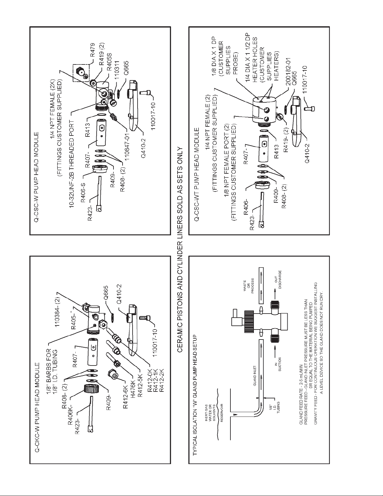
For maximum pump performance, mount
the pump with motor at 12 o’clock and
pump head at 6 o’clock position. This orientation will allow air bubbles that enter
the pumping chamber to directly exit thru
buoyant assist. Discharge lines should be
inclined upward from pump head.
IMPORTANT
RECOMMENDED FMI PUMP MOUNTING FOR MAXIMUM
PERFORMANCE
GOOD
BETTER
BEST
NOT
RECOMMENDED
figure 1
figure 2
KNURLED
NUTS
Q424
R408
R409
figure3
figure 4
DRIVE PIN
R423
R406
Page 4
4
IN-Q431-09A
Page 5
5
IN-Q431-09A
IMPORTANT!
WHEN ORDERING REPLACEMENT PARTS PLEASE MEN-
TION MODEL AND SERIAL NUMBERS OF THE PUMP ON
WHICH THEY WILL BE USED.
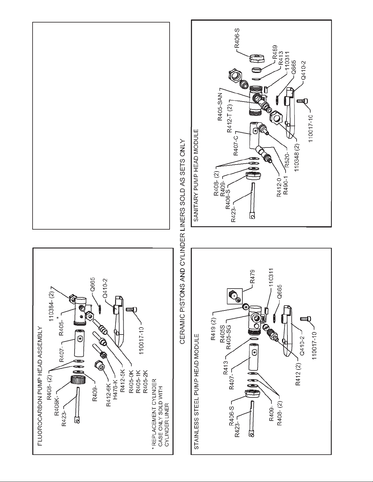
REPLACEMENT CYLINDER CASE (R405-K) ONLY SOLD
WITH CYLINDER LINER
CERAMIC PISTONS & CYLINDER LINERS SOLD AS SETS
ONLY
PLEASE NOTE: FMI will PROVIDES A REPAIR ESTIMATE
WITHIN 48 HOURS (SEE PAGE 7 FOR DETAILS)
Page 6
PUMP HEAD INFORMATION
THINGS YOU SHOULD KNOW BEFORE ORDERING THE FLUID HANDLING PORTION (or
parts thereof) OF AN FMI MODEL Q PUMP, i.e.
the removable assembly that is often referred to
as the liquid end, the piston/cylinder set, or the
Pump Head Module (PHM) assembly.
To accommodate the diverse demands of laboratory and industrial pumping applications, FMI’s QPumps are arranged to accept interchangeable
PHM’s with differing chemical and mechanical
characteristics. There are a number of these assemblies from which the pump user may select in
solving difficult fluid pumping problems.
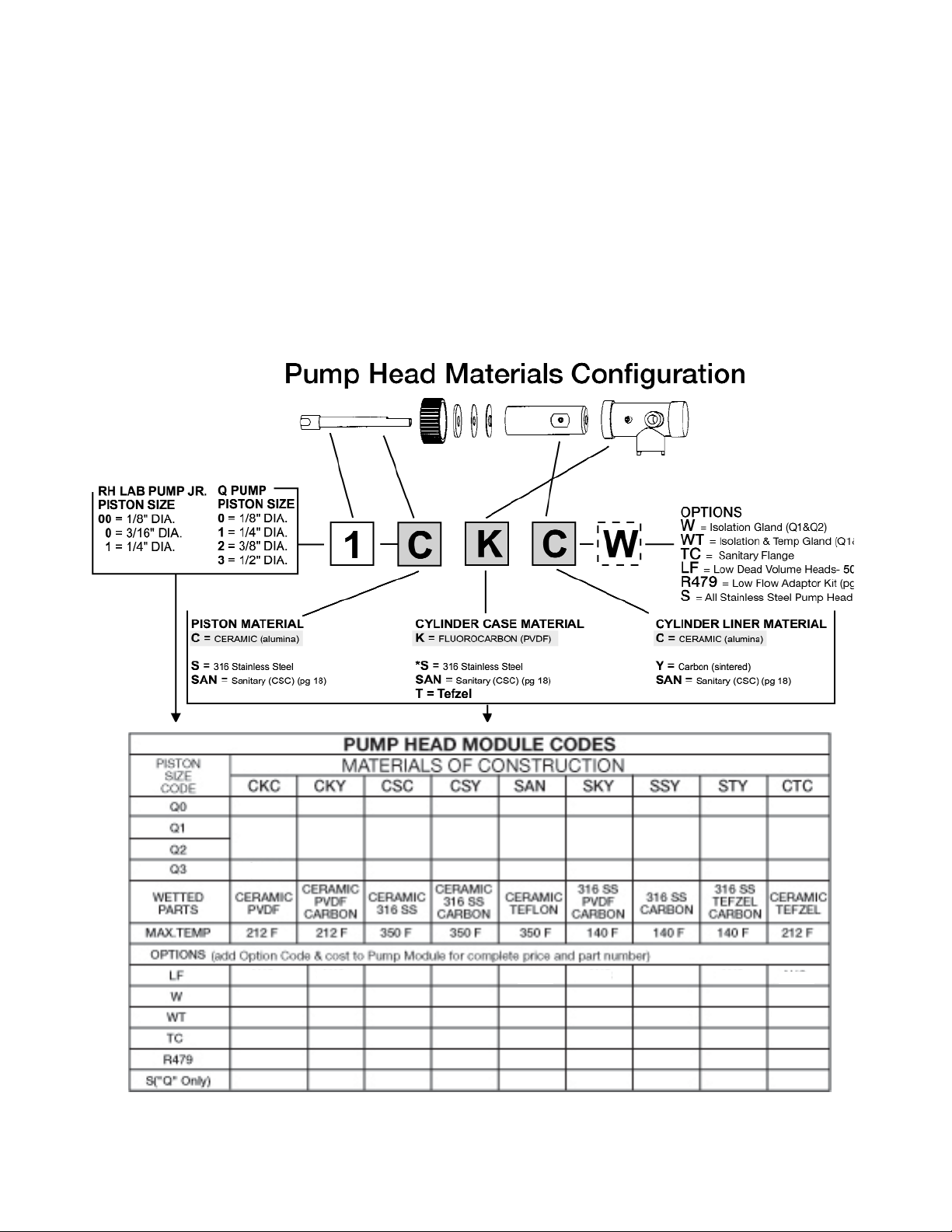
To simplify the selection process, each individual
type of fluid handling assembly (piston/cylinder
set) is designated by an alpha-numeric code which
permits direct identification of pertinent factors.
Q-PUMP DESIGNATIONS
Example:
Q-1-SAN denotes a sanitary construction pump
head assembly having a 1/4” diameter ceramic
piston, ceramic cylinder liner and a 316 stainless
steel cylinder case.
PLEASE NOTE:
1. When the last three of the above shown categories are not called out, standard materials and
construction are implied (CKC).
2. If SAN is designated in the last category, the
preceding three categories will be designated CSC
as required by FDA specifications.
3. Piston seals made of an inert material, Rulon
AR, are used in all FMI type Q Pump Heads except
high speed pumps fitted with stainless steel pistons (these use Rulon J seals) and sanitary (SAN)
pump heads which require virgin Teflon (T) seals.
Specify AR, J or T after the pump head code designation to order pump heads assembled with
other than standard seals.
4. Ceramic cylinder liners should be used with ceramic piston only.
6
IN-Q431-09A
See Materials of Construction section in the Fluid Metering catalog for more information on wetted parts *316 Stainless Steel
cylinder cases accept ¼ NPT male fittings.
When ordering specify: Piston Size Code + Material of Construction + Option Code (Q1+CKC+W = Q1CKC-W
*CF = Consult factory for details
CF CF CF CF
CF
CFCF
CF
Page 7

7
IN-Q431-09A
Q PUMP HEAD MODULE - PARTS PRICE LIST
PUMP HEAD REPAIR SERVICE
Should your FMI PUMP or PUMP SUBASSEMBLY need repairs, you should first contact the Customer Service
Department for a SERVICE SAFETY ASSURANCE FORM and a RETURN AUTHORIZATION NUMBER, you
may then ship it to us post-paid. You will be charged a flat service fee for each Pump Head Module returned plus
the cost of parts used and the postage required to return it to you. The Pump Head Module service fee includes
inspection, clean and test to agreed specifications and the replacement of Lip Seals and Gland Washer.
After examining a returned pump or subassembly by FMI Service Department, you will be requested to approve
the charges before repair work is started.
PARTS ORDERS
MINIMUM ORDER APPLIES FOR DOMESTIC or FOREIGN (Invoice price exclusive of shipping)
SHIPPING
Parts and repair orders will be shipped via United Parcel Service or U.S. Postal Service unless other
means are specified.
ALL PRICES ARE QUOTED IN U.S. DOLLARS, FOB SYOSSET, NY - Subject to change without no
tice.
For Additional Information Call - Toll Free 800-223-3388 or email us at: pumps@fmipump.com
* CERAMIC PISTONS & CYLINDER LINERS SOLD AS SETS ONLY
PART NO. DESCRIPTION
Q410-2 CARRIER
Q410-3 CARRIER STAINLESS STEEL
Q665 SPACER
R405-S CYL CASE, STAINLESS STEEL
R405-1S CYL CASE, SS, TEMP GLAND
R405-SAN CYL CASE, SANITARY STAINLESS STEEL
R405-SG CYL CASE, SS ISOLATION GLAND
R406-K GLAND NUT, FLUOROCARBON
R406-0K GLAND NUT, FLUOROCARBON 1/8” PISTON
R406-1K GLAND NUT, FLUOROCARBON 1/4” PISTON
R406-2K GLAND NUT, FLUOROCARBON 3/8” PISTON
R406-3K GLAND NUT FLUOROCARBON
R406-S CYLINDER NUT R405-S, R405-SAN
R407-0 CYLINDER LINER
R407-1 CYLINDER LINER
R407-2 CYLINDER LINER
R407-1C* CYLINDER LINER
R407-2C* CYLINDER LINER
R407-3C* CYLINDER LINER
R408-1A LIP SEAL, RULON AR 1/4”
R408-2A LIP SEAL, RULON AR 3/8”
R408-0J LIP SEAL, RULON J 1/8”
R408-1J LIP SEAL, RULON J 1/4”
R408-2J LIP SEAL, RULON J 3/8”
R408-1T LIP SEAL, TEFLON 1/4”
R408-2T LIP SEAL, TEFLON 3/8”
R408-3A LIP SEAL, RULON AR 1/2”
R408-3T LIP SEAL, TEFLON 1/2”
R409-0 GLAND WASHER, TEFLON 1/8”
R409-1 GLAND WASHER, TEFLON 1/4”
R409-2 GLAND WASHER, TEFLON 3/8”
R409-3 GLAND WASHER TEFLON 1/2”
PART NO. DESCRIPTION
R412-1 ADAPTER, S.S. 1/4 NPT TO 1/4” I.D. TUBE
R412-2 ADAPTER, S.S. 1/4 NPT TO 3/8” I.D. TUBE
R412-0K ADAPTER, FLUOROCARBON 1/8” I.D. TUBE
R412-1K ADAPTER, FLUOROCARBON 1/4” I.D. TUBE
R412-2K ADAPTER, FLUOROCARBON 3/8” I.D. TUBE
R412-5K ADAPTER, FLUOROCARBON 1/4-28 THD
R412-6K ADAPTER, FLUOROCARBON 1/2” I.D. TUBE
R412-07 ADAPTER, S.S. 1/4” I.D. TUBE, SAN
R412-08 ADAPTER, S.S. 3/8” I.D. TUBE, SAN
R412-1T ADAPTER, TEFLON 1/4” I.D. TUBE, SAN
R412-2T ADAPTER, TEFLON 3/8” I.D. TUBE, SAN
R413 CYLINDER HEAD SEAL
R413-1 CYLINDER HEAD SEAL, R405-1K
R419 CYLINDER PORT SEAL, R405-S
R423-1C* PISTON
R423-2C* PISTON
R423-3C* PISTON
R423-0S PISTON
R423-1S PISTON
R423-2S PISTON
R479 LOW FLOW KIT (FITS R405-S)
R489 SPACER, SANITARY CYLINDER GROUP
R490-1 PORT SLEEVE, SANITARY CYLINDER GROUP
R520-1T ADAPTER, TEFLON 1/4” O.D. STRAIGHT, SAN
R520-2T ADAPTER, TEFLON 3/8” O.D. STRAIGHT, SAN
H476-K SML TUBE ADAPTER SET, 1/8” O.D. (OPTL)
110017-10 SCREW, SKT HD CAP 1/4-20 X 5/8”
110311 NUT, SQUARE 1/4-20
110348-P SAN PORT NUT, PLASTIC
110348-S SAN PORT NUT, STAINLESS STEEL
110384-K FERRULE NUT 1/4, KYNAR
110384-T FERRULE NUT 1/4”, TFE
110847-01 BARBED FITTING 10-32 UNC-2B 1/8” ID TUBING
200182-01 CYL CASE, SS HIGH TEMP GLAND
500074 LIP SEAL INSTALLATION TOOL,1/8”
500071 LIP SEAL INSTALLATION TOOL,1/4”
500080 LIP SEAL INSTALLATION TOOL,3/8”
500081 LIP SEAL INSTALLATION TOOL,1/2”
Please
call for Pricing
Please
call for Pricing
Page 8

8
IN-Q431-09A
FMI MODEL Q PUMPS
PARTS IDENTIFICATION SHEET Q431-05
Page 9

9
IN-Q431-09A
FMI MODEL Q PUMPS
PARTS IDENTIFICATION SHEET Q431-05
IMPORTANT!
WHEN ORDERING REPLACEMENT PARTS,
PLEASE MENTION MODEL & SERIAL NUMBERS OF PUMP ON WHICH THEY WILL BE
USED.
FOR ADDITIONAL INFORMATION CALL
TOLL FREE 800-223-3388 or
516-922-6050 / FAX 516-624-8261
email: pumps@fmipump.com
110522/200635
IVSP1 PUMP DRIVE MODULE
Special order
Page 10

General Description
The V300 Stroke Rate Controller provides precision flow control for FMI variable speed "V" Series
pumps. The V300 accomplishes this by varying
the pump stroke rate from 5% to 100% of the
drive’s rated speed range of 90 to 1800 Strokes
per Minute (SPM) or 5-50 strokes. The complete
pump system consists of the V300 Controller and
a variable speed "V" Series Pump. The V300 and
pump are connected via a single cable (standard
length is 4 meters while optional extension cables
up to 20 meters are readily available).
The pump is comprised of a 90 volt DC pump drive
module (PDM) with integrally mounted pump head
module (PHM), and is available in two configurations, QV and RHV, to accommodate FMI's full
range of pump head sizes.
V300 Features:
• 3 1/2 Digit LCD displays percent of Flow/Speed.
• Selectable Manual or Analog flow rate control.
• Manual setting of flow rate with 0.1%
adjustability
• Analog Input selectable 4-20 mA, 0-5 VDC, and
0-10 VDC input for communication with proces instrumentation.
• Start, Stop, and Reverse Flow while maintaining
flow settings.
• Current fold back eliminates stalled motor/ electronics damage.
• Universal Power accepts 100-240 VAC 50/60 Hz
• Quick connections for power, analog input, and
pump modules.• Rugged, An odized Aluminum
Enclosure designed for bench-top or wall
mounting.
10
IN-Q431-09A
V300 STROKE RATE FOR
CONTROLLER
FOR
MODELS QV, Q2V, QVG50, & RHV
For more information refer to our W300 Instruction manual available at our website at www.fmipump.com under literature.
Page 11

11
IN-Q431-09A
PART NO. DESCRIPTION
Q421-1 BASE ASS’Y QP
Q421-3 BASE ASS’Y QB, QD,QV, QBG
Q421-4 BASE ASS’Y QSY
Q421-5 BASE ASS’Y QSYX
Q421-6 BASE ASS’Y QG, QVG50
Q421-7 BASE ASS’Y QDX
Q424 SPINDLE ASSEMBLY QP, QDX
Q447 BUSHING, FLOW CONTROL
Q454-3 FOLLOWER
Q464 STROKE LENGTH ADJUSTMENT KNOB
Q485 DIAL INDICATOR KIT
Q616 RETAINER ASSEMBLY
Q647 BASE MOUNTING KIT
Q662 TILT STAND KIT
R424-1 SPINDLE ASSEMBLY QD, QG, QB, QV, QVG
R424-6 SPINDLE ASSEMBLY QSY, QSYX
R475 FOOT QSYX
P56C FACE MOTOR ADAPTER KIT
V109 MOTOR ASSEMBLY QV
V109G MOTOR ASSEMBLY QVG50
110049 WASHER #8 INT. LOCK
110258 FOOT, RUBBER
110262 MOTOR, QD PUMP 115V, 60Hz
110262-2 MOTOR, QD PUMP 230V , 50/60 Hz
110286-6A MOTOR, QG 6 RPM 115V, 60Hz
110286-20A MOTOR, QG 20 RPM 115V, 60 Hz
110286-50A MOTOR, QG 50 RPM 115V, 60 Hz
110286-150A MOTOR, QG 150 RPM 115V, 60 Hz
110286-400A MOTOR, QG 400 RPM 115V, 60 Hz
110290-8 SCREW, SKT HD 8-32 X 1/2”
PART NO. DESCRIPTION
110290-10 SCREW, SKT HD #8-32 X 5/8”
110290-22 SCREW, #8-32 X 1 3/8”
110297-6 DRIVE SCREW , 8-32 X 3/8”
110306-1 MOTOR, QSY 115V, 60Hz
110306-2 MOTOR, QSY 230V, 50/60Hz
110314 WASHER, #10 INT. LOCK
110336-2 MOTOR 230 VAC 50/60Hz QSYX
110337-2 RESISTOR (110336-2 230V, 50/60Hz)
110338-2 CAPACITOR (110336-2 230V, 50/60Hz)
110355-1 MOTOR, 12 VDC QB
110373 DRIVE COUPLING
110376-16 BOLT, HEX HD 3/8 -16 X 1”
110417-4 STANDOFF, HEX 8-32 X 1/4Ó FEM.
110454 CAP NUT 8-32
110471 LOCK NUT 1/4-20
110491 WASHER, FLAT 1/4” STD
110505 WASHER, SHOULDER, NYLON
110506-8 SCREW, SKT HD CAP 10-32 X 1/2”
110509 ADAPTER, PC56C
110522 MOTOR, X-PROOF QDX 115/230 VAC 60 HZ
110542-6 SCREW, HEX HD NYLON 8-32 X 3/8”
110544 SPEED KNOB
110579 WASHER, FLAT 3/8”
110580 WASHER, LOCK INT. 3/8”
110608 SPRING AND BRUSH SET, QVG50
110609 BRUSH CAP , QVG50
110671-4 SCREW, SET 8-32 X 1/4”
110837-01 SPRING BRUSH SET 12 VDC - GRAY MOTOR
110838-01 SPRING BRUSH SET 90 VDC - GRAY MOTOR
110839-01 BRUSH CAP 12, 90 VDC - GRAY MOTOR
110877 SPACER
200635 Motor + Cable ASS’Y, 1/2HP,230 VAC
Q PUMP DRIVE MODULE - PARTS PRICE LIST
PUMP DRIVE REPAIR SERVICE
Should your FMI PUMP DRIVE or SUBASSEMBLY need repairs, you should first contact the Customer
Service Department for a RETURN AUTHORIZATION NUMBER; you may then ship it to us post-paid.
You will be charged a flat service fee for each Pump Drive Module or subassembly returned plus the
cost of parts used and the postage required to return it to you.
After examining a returned pump or subassembly by FMI Service Department, you will be requested
to approve the charges before repair work is started.
PARTS ORDERS
MINIMUM ORDER APPLIES FOR DOMESTIC or FOREIGN (Invoice price exclusive of shipping)
SHIPPING
Parts and repair orders will be shipped via United Parcel Service or U.S. Postal Service unless other
means are specified.
ALL PRICES ARE QUOTED IN U.S. DOLLARS, FOB SYOSSET, NY - Subject to change without
notice.
For Additional Information Call - Toll Free 800-223-3388 or email us at: pumps@fmipump.com
Please
call for Pricing
Page 12

Continued from page 3
j) Place head seal components R413 and R489
into the head end of CYLINDER CASE R405SAN, apply CYLINDER NUT R406-S..
k) Wrench tighten each PORT NUT 110348-P 1/6
turn.
l) Wrench tighten each CYLINDER NUT R406-S
1/2 turn, piston end first.
18. PISTON SEAL REPLACEMENT (please see
para 5.) When R408 SEALS are replaced, the
following procedure should be followed: (please
see figs. 3,4)
a) Place GLAND NUT R406 and GLAND
WASHER R409 on PISTON ASSEMBLY R423.
b) Place the lip seal installation tool over the end
of the piston. Slide the tool until piston is seated
in tool. (See lip seal insertion tool table bellow).
c) First “Form” lip of lip seal by gently placing a
lip seal R408 on tool, lip side last. Carefully rotate the seal on the tool while sliding the seal
over the tool’s neck to avoid damage to the lip.
Then remove seal and reverse lip direction
(FIG.3)
d) Gently place one “formed” LIP SEAL R408 on
piston, lip side first, carefully rotating the seal on
the tool until it is past the tool and on the piston
e) Gently place one LIP SEAL R408 on piston,
lip side last. Carefully rotate the seal on the tool
to avoid damage to the lip while passing over the
tool to the piston (fig. 4).
f) Remove installation tool from the piston.
g) Insert piston into cylinder approximately one
inch.
h) Apply GLAND NUT R406 to cylinder threads,
seat gland nut, then tighten to 1/3 turn maximum.
19. PISTON SEAL SETTING. After installing
new
lip seals (part R408) in pump head it is recommended that the seals be set (formed in place)
by fluid pressures generated by pump action. To
accomplish this:
a) Operate the pump spindle clockwise for 10 or
20 strokes at maximum setting, handling water
(left to right mode facing pump head) with suction
line blocked or pinched off. This will create a
vacuum in the pump head, permitting atmospheric pressure to shape the outer seal member
tightly around the piston.
b) Reverse the pumping direction (pump head
angle reversal) and intermittently block the line
leading from the left hand port. This will generate
pressure in the seal area of the pump head,
causing the inner seals to form intimately around
the piston.
12
IN-Q431-09A
WHEN ORDERING REPLACEMENT PARTS PLEASE MENTION MODEL AND SERIAL NUMBERS OF
THE PUMP ON WHICH THEY WILL BE USED.
Record your Model and Serial Numbers below. This will be useful when ordering replacement parts.
PUMP HEAD MODULES (PHM) PUMP DRIVE MODULE (PDM)
PHM MODEL NUMBER PHM SERIAL NUMBER PDM MODEL NUMBER PDM SERIAL NUMBER
_____________________ QB__________________ _____________________ QA__________________
_____________________ _____________________ _____________________ ____________________
_____________________ _____________________ _____________________ ____________________
_____________________ _____________________ _____________________ ____________________
PLEASE NOTE:
Pistons and cylinders are dimensionally mated. For most satisfactory performance, they should be ordered
as mated sets.
 Loading...