

Page 1

Franklin Manufacturing Inc.
* Job# F3138 *
Model# PTW72 Horizontal
Welding Machine For 72" Wide Webs
Serial# 2724-A819600
PO Drawer 998 / Russellville, AL. 35653 / (256) 332-6654
Page 2

DETAILED WARRANTY
Franklin Manufacturing, Inc. warrants the machine tools and systems manufactured and shipped by Franklin to
be free from defects in material and workmanship for twelve (12) months from shipment date from Seller’s
factory or 2000 operating hours which ever comes first provided: (a) they are used only by the original Buyer,
(b) they are given normal and proper usage, care and maintenance as specified by Seller, (c) all electrical and
mechanical connections are made in accordance with Seller’s specifications, and (d) proper installation and
start up procedures are employed by qualified personnel (in the case of CNC units, only Franklin
Manufacturing Inc. trained personnel will be considered qualified).
Consumable items, such as light bulbs, fuses, switches, plasma torch consumables, shear blades, hard tooling,
and filters, etc. are not warranted.
This warranty does not cover (by way of example): (a) any component damaged by improper Buyer-supplied
voltages, improper electrical connections to the machine, or improper electrical grounding techniques, (b) any
component damaged by arc welding on or near the machine, or (c) the routine replacement of consumable
mechanical and electrical components and the adjustments necessary for optimum machine performance,
which are the responsibility of the Buyer.
Notice of any warranty claim must be presented to Seller immediately upon Buyer’s discovery of the defect and
right of inspection must be given to Seller while the product is in the claimed defective condition, and
operation of the product must be suspended until written clearance is issued for continued operation. During
this time the seller will not be responsible for “Down Time”. For a warranty claim notify the Seller’s
customer service office (256) 332-6654.
Upon receipt of a warranty claim notice, Seller will proceed without unreasonably delay to remedy any defect
found to exist under the terms of warranty. During the warranty period, parts found to be defective after
Seller’s inspection, will at Seller’s option be repaired, or replaced with new or factory rebuilt parts free of
charge, except that freight charges, Custom charges, or other associated fees involved with returning the
defective component to Seller, and the shipment of the replacement component, will be the responsibility of
the Buyer.
During the twelve (12) months or 2000 operating hours warranty period if Seller’s service technicians are
required to perform any function at the Buyer’s facility, there will be no charge for labor. However, Buyer
will compensate Seller for the cost of travel (time and expenses) and living expenses.
VENDOR SUPPLIED GOODS: Vendor supplied items shall be warranted in accordance with the available
Warranty, if any, provided to Franklin Manufacturing Inc., by the vendor. Claims relating to vendor supplied
items will be dealt with on a case-by-case basis.
THERE ARE NO WARRANTIES, WHICH EXTEND BEYOND THE DESCRIPTION AND THE
WARRANTIES CONTAINED HEREIN. THE WARRANTIES EXPRESSED HEREIN ARE IN LIEU OF
ANY OTHER WARRANTIES, EXPRESSED OR IMPLIED. ANY IMPLIED WARRANTY OF
MERCHANTABILITY AND IMPLIED WARRANTY OF FITNESS FOR A PARTICULAR PURPOSE
ARE HEREBY EXCLUDED. BUYER’S REMEDY IS LIMITED TO, AND SELLER’S MAXIMUM
LIABILITY SHALL NOT EXCEED, EITHER (1) REPAIR OR REPLACEMENT OF THE DEFECTIVE
PART OF PRODUCT OR, AT SELLER’S OPTION, (2) RETURN OF THE PRODUCT AND REFUND OF
THE PURCHASE PRICE SUCH REMEDY SHALL BE BUYER’S ENTIRE AND ONLY REMEDY.
WARRANTY START DATE:
MACHINE HOURS:__________ MACHINE SERIAL NUMBER
At installation ACCEPTED BY BUYER:_______
2724
Page 3

CONTENTS
Introduction:
Operation & Maintenance Manual
Terms & Conditions of Sale
FMI Equipment Sheet
Section #1: Operation & Maintenance
Section #2: Assembly & Parts List
Section #3: Electrical Information
Section #4: Hydraulic Power Unit Information
Section #5: Pneumatic Information
Page 4

Warning: cThe hydraulic power unit must be locked off before performing any
maintenance or tool change. d Keep hands clear from any moving object on the
machine. e Safety glasses are recommend for operators or anyone near the machine
during operation.
Operating and Maintenance Manual
This manual contains essential information regarding recommended operational and
maintenance procedures. It should be thoroughly read by persons operating and
maintaining this equipment.
WARNING NOTE: In accordance with OSHA standards we recommend the use of
eye protection equipment during the operation of this machine. The hydraulic power
unit should be locked in the OFF position during any maintenance or tool change.
Seller shall not be liable to buyer or any other person for any damage, injury, or loss
arising out of the use of the goods whether by reason of any defect in the goods or
otherwise if, prior to such damage, injury or loss, such goods are: c Damaged or
misused following shipment; or d Repaired, altered, or modified without sellers
written consent; or e Not installed, maintained and operated is strict compliance
with the instructions furnished by seller.
Indemnification - Safe Operation: Buyer shall comply with and require its employees
to comply with directions set forth in manuals, drawings, or instruction sheets
furnished by seller. Buyer shall use and require its employees to use reasonable care
and all safety equipment in the operation and maintenance of the goods. Buyer shall
not remove or permit anyone to remove any safety equipment or warning signs
unless suitable alternate safeguarding equipment is provided by the buyer. Buyer
shall operate goods in compliance with existing applicable laws and/or regulations.
In the event of bodily injury or damage followed by prompt written confirmation,
buyer shall cooperate with seller in investigating any such injury or damage and in
the defense of any claims arising therefrom.
If buyer fails to observe any obligation in this section, or if any injury or damage is
caused, in whole or in part, by buyer's failure to comply with applicable federal,
state, or local safety requirements, seller shall have no obligation to buyer and buyer
shall indemnify and hold seller harmless against any claims, loss, or expense for
injury or damage arising from the use of the goods.
(a) F.O.B. Point of origin.
1. Prices:
Conditions of Sale
Page 5

(b) Subject to change without notice at any time prior to acceptance of purchaser’s order by seller’s home office, as evidenced by seller’s formal
acknowledgment.
(c) Firm upon seller’s acceptance of purchaser’s order as evidenced by seller’s formal acknowledgment unless escalation terms are included in terms of sale.
(d) Prices do not include sales, use, excise, or similar taxes. Consequently, in addition to the prices specified, the amount of any prese nt or future sales, use,
excise or other similar tax applicable to the sale or use of the equipment shall be the responsibility of a nd paid by the purchaser; or in lieu thereof, the
purchaser shall provide the seller with a tax-exemption certificate acceptable to the taxing authorities.
2. Shipping Schedule:
(a) Computed from the date of acknowledgment of the order or, in the case of special items, from the date seller receives complete information necessary to
proceed with design and manufacture.
(b) The shipping date specified is:
1. Subject to prior sale before seller’s receipt of order.
2. Subject to any mandatory changes that may be caused by procedures or priorities which may be set up by the U.S. Government or any of its
agencies.
3. Seller shall have no liability for loss or damage resulting from a delay in scheduled delivery caused by wa r, riots, strikes, labor disputes, fires,
serious accidents, delays in receipt of parts or materials for suppliers or subcontractors, design or engineering problems relating to purchaser’s
order, natural disasters, delay in shipping items needed by seller to test or complete purchaser’s order, or any other circumstances beyond seller’s
control. Franklin Manufacturing Inc. will honor your position in our production, and do our very best to deliver at the earliest date after thorough
inspection.
4. Under no circumstances shall seller have any liability whatsoever for loss of use or for any direct, indirect or consequential damages due to delay in
scheduled delivery.
3. Electrical Equipment:
(a) Supplied by seller and will be the make mutua lly agreed.
(b) When not supplied by seller, is to be purchased in accordance with seller’s detailed specifications, and will be subject to an installation charge for
mounting and wiring at seller’s factory.
(c) Wiring and protecting conduit from purchaser’s power supply to the machine control is not included in seller’s quotation.
4. Warranty:
(a) Any product or part thereof covered by selle r’s quotation which, under normal operating conditions in the plant of the original purchaser thereof, proves
defective in material or workmanship within one (1) year from the date of shipment from seller’s plant, (as determ ined by an inspection by seller) will
be replaced free of charge, F.O.B. factory, provided that purchaser promptly sends to seller notice of the defect and establishes that the product has been
properly installed, maintained and operated within the limits of rated and normal usage. Electrical equipment not manufac tured by Franklin
Manufacturing Inc. is not included in this warranty, those motors, controls, plus hydraulic items being covered by the warranty of the respective
manufacturer.
(b) Said warranty in respect of replacement of defective parts and any such additional w arranty or representation expressly made a part of seller’s quotation
are in lieu of all other warranties expressed or implied including any implied warranty of merchantability.
(c) Under no circumstances shall seller, (any subsidiary or any division thereof), have any liability whatsoever for loss of use or for any direct, indirect or
consequential damages.
(d) The warranty is limited to the first purchaser and is not transferable.
5. Production Estimates and Perfor mance:
(a) All working drawings or other materials provided by seller are for general information purposes only, and may not relate to purchaser’s order or other
machines or equipment. Any spec i fications contained therein are not binding on seller except as expressly so stated in this form or other written form.
Seller reserves the right to make, at any time, such changes in detail of design or construction as shall in the sole judgment of seller constitute an
improvement in operation and/or safety ove r former practice.
(b) Production data, where given is based on seller’s careful analysis and understanding of the specific re quirement, material spec i fications, required
accuracy and handling facilities is nonetheless an estimate only and is not guaranteed or warranted. Franklin Manufacturing Inc. reserves the sole right
to determine machine capacity, and in no event shall sellers be responsible for capa city figures supplied by seller’s suppliers
parties.
6. Cancellation:
(a) Following acceptance by seller, this order may not be canceled without written consent of the seller.
(b) Seller shall have the absolute right to cancel and refuse to complete this order (1) if any time all terms and conditions governing this order (including any
requirement of progress payments) are not strictly complied with by the purchasers, and/or (2) if at any time the purchaser becomes bankrupt or
insolvent.
(c) In the event of cancellation by seller as above set forth or of a request by the purchaser to stop work or to cancel the whole or any part of an order, the
purchasers shall make payments to the seller as follows:
1. Any and all work that can be completed within 30 days from date of notification to stop work on account of cancellation shall be completed, shipped
and paid for in full.
2. For work in progress and any materials and supplies procured or for which definite commitments ha ve been made by seller in connection with the
order, the purchaser shall pay to the seller the actual costs and overhead expenses determined in accordance with generally accepted accounting
practice plus 15%.
7. Payment Terms:
Net 30 days from date of invoice, shipment date. (Interest added after 30 days at 1¾ % pe r month.)
All orders must clearly state name and address of purchaser, shipping instructions, and all conditions, mechanical and otherwise with which the manufacturer is
Delivery of items of any order to the carrier by seller consigned to purchaser, or as purchaser shall direct, shall constitute transfer of title, ownership, possession
The foregoing comprises seller’s and purchaser’s entire agreement. On any order placed pursuant hereto, the above provisions entirely supersede any prior oral
Wherever used herein, SELLER shall mean Franklin Manufacturing Inc.; PURCHASER shall mean the customer placing the purchase order
8. Acceptance of Orders:
expected to comply. The seller shall furnish written “order acknowledgment” which shall constitute the seller’s acceptance of the order upon the terms and
conditions specified in the “order acknowledgme nt”.
9. Title:
and property in and to such items at such point of delivery; such carrier shall thereafter be deemed to be acting for the purchaser and the said items thereafter
shall be at the purchaser’s risk; provided, however, that seller reserves all right to stoppage in transit and to repossess said items, notwithstanding delivery to
the carrier, until full payment of purchase price is made to the seller.
10. General:
or written correspondence, quotation or agreement. There are no agreements between seller and purchaser in respect of the product quoted herein except as
set forth in writing and expressly made part of this quotation. There shall be no modification to the foregoing except as entered into by writing, signed by
seller and purchaser. The designs and specifications of all products sold by seller are subject to change without notice and, in the event of any such changes,
seller will have no obligation whatsoever to make similar changes in a product previously ordered by purchaser.
with seller.
or other cooperating
Page 6

Section #1: Operation and Maintenance
Operation & Console Functions
Web Splice Station Console
Figure 1
Web Splice Button Layout
a. E-STOP/CONTROL POWER - Removes AC power to all PLC outputs.
Pull UP to enable.
b. INFEED Off/On - A selector switch that controls power to the infeed
conveyor.
c. OUTFEED Off/On - A selector switch that controls power to the outfeed
conveyor.
d. SPEED Lo/Med/Hi - A selector switch that controls conveyor speed.
e. JOG MOVE DIRECTION Forward/Reverse - Two push buttons that control
direction of conveyor(s). The "INFEED" and/or "OUTFEED" selector
switch(s) must be on the "On" position.
Page 7

f. Outfeed Control Web\Tack Placing switch in the Web position will allow
control of the outfeed conveyor at the web splice station control panel.
Placing switch in the Tack position will allow control of the outfeed
conveyor from the Tack station control panel.
g. GANTRY SPEED-LO-MED-HI—Use to select low, medium, or high speed
for gantry traverse movement
h. GANTRY MAGNET POWER—Use to vary the strength of the magnets on
the gantry lift beam.
i. GANTRY TRAVERSE-ENABLE-DISABLE—Place switch in the ENABLE
position to allow gantry traverse movement. Place this switch in DISABLE to
prevent gantry traverse movement.
j. UP-DOWN-REV-FWD—Use to manually jog the gantry traverse in the
forward and reverse direction. Also use to manually move the lift beam up
and down.
2
Page 8

3
Page 9

Franklin Tack Station
a. E-STOP/CONTROL POWER - Removes and restores power to all control
functions of the machine. Pulling UP fully on the button will start the
hydraulic unit and enable all functions of the machine. Push in on the
button to stop the hydraulics and disable all machine functions.
b. DATUM SIDE MAG-CON-REV/FWD- Allows movement of the magnet
rollers forward and reverse. Use to position the flange closest to the
operator once it has been placed on end.
c. DATUM SIDE FLANGE UPENDERS- UP/DOWN- Switch to UP to bring
the flange on the datum side up on it’s end.
d. FLANGE UPENDERS-1 IN/OUT- Use to position the flange upender
assemblies on the first conveyor. Allows positioning of the flange across
the conveyor.
e. STOP GATE Down/Up - Turn switch to control Stop Gate position.
f. OUTFEED CONVEYOR; INFEED CONVEYOR; On/Off - Each selector
switch controls the power to the appropriate conveyor drive. Used to jog
the conveyors that are selected to run.
g. CONVEYORS REV/FWD – Place switch in FWD to move conveyors in the
forward direction. REV moves conveyors in the reverse direction.
h. CONVEYOR SPEED- LOW/MED/HIGH- Use to select between three
ranges of conveyor speeds. Conveyors will travel at the slowest rate when
LOW is selected.
i. ALL CONVEYORS FORWARD—Use to jog all conveyors forward
simultaneously.
j. WEB LIFT Down/Up - Turn switch to control Web Lift position.
k. FLANGE CLAMP-CLOSE-OPEN—Use to open and close the flange
clamp.
l. FLANGE UPENDERS-2 IN/OUT- Use to position the flange upender
assemblies on the second conveyor. Allows positioning of the flange across
the conveyor.
m. OPOSITE DATUM SIDE FLANGE UPENDERS- UP/DOWN- Switch to
UP to bring the flange opposite the datum side up on it’s end.
n. OPOSITE DATUM SIDE MAG-CON-REV/FWD- Allows movement of the
magnet rollers forward and reverse. Use to position the flange opposite the
operator once it has been placed on end.
o. BEAM CLAMP- OUT/IN- Closes and opens the beam clamp. Use to clamp
front of beam in preparation for welding.
p. MAGNET- OFF/ON- Select ON to turn on the web magnets. Use to pull
down and hold the web, once positioned, in preparation for welding.
q. Tack\PTW - Place switch in Tack position to allow operation of the outfeed
conveyor from the tack station control panel. Placing switch in PTW position
4
Page 10

enables control of the outfeed conveyor from the pull thru welder control
panel.
r. Web Outfeed – Use to control the direction of the outfeed conveyor.
Pull Thru Welder Controls
Pull-Thru-Welder Operator Controls
a. E-STOP/CONTROL POWER - Removes AC power to all PLC outputs.
Pull UP to enable.
b. PTW INFEED Jog/Run - PTW OUTFEED Jog/Run - Selector switch to
activate manual control of conveyor. When in Jog conveyor will be
operated by the PTW INFEED(or OUTFEED)-Rev/Fwd selector switch.
When RUN is selected the conveyor(s) will run continuous and at a higher
rate than when JOG is selected.
c. PTW INFEED- REV/FWD; PTW OUTFEED-REV/FWD- Use to manually
jog the infeed and outfeed conveyors. Hold PTW INFEED in REV to move
the infeed conveyor in the reverse direction. Hold the PTW INFEED in
FWD to move the infeed conveyor in the forward direction. Conveyor(s)
5
Page 11

will stop when switch is released. The PTW OUTFEED switch performs
the same functions for the outfeed conveyor.
d. WELDER Jog - Use to bring material into weld to position for weld.
Conveyors jog with this function.
e. WELDER ON – This is an indicator that will be illuminated when one or
both of the welders are welding.
f. WELD DIRECTION Rev/Fwd – Use to run the welder drive wheels either
forward or reverse.
g. CYCLE START – Use to start the machine automatic processing mode.
Pressing Cycle-Start will cause the machine to begin automatic processing.
h. CYCLE HOLD – Use to stop the machines automatic operation. Pressing
the
button will discontinue the automatic machine processing.
i. PRESSURE WHEELS Open/Close – These two switches control the
pressure wheels on the movable side of the machine. The left switch will
cause the infeed side of the pressure wheel assembly to move in or out. The
switch on the right will cause the outfeed side of the pressure wheel
assembly to move in or out.
j. COPPER WHEELS Out/Weld – The switch on the left is used to open or
close the copper backup wheel on the stationary side of the machine. The
switch on the right is used to open or close the copper backup wheel on the
movable side of the machine.
k. ELECTRODES Up/Weld – Placing the switch on the left in Weld will cause
the electrode head on the stationary side of the machine to move down and
in against the beam. Placing the switch on the left in UP will cause the
electrode head on the stationary side of the machine to move up and out.
The switch on the right performs the same functions for the electrode head
on the movable side of the machine.
l. FLUX VALVES Off/Weld - Selector switch to control flow of flux through
welding head. Placing the switch on the left in Weld will allow flux to flow
from the head on the stationary side of the machine. Placing the switch on
the left in Off will stop the flow of flux on the stationary side. The switch
on the right performs the same functions for the flux system on the movable
side of the machine.
m. CARRIAGE Up/Down - Push buttons to control carriage position. Pressing
UP will cause the internal machine assembly(carriage) to move up.
Pressing DOWN will cause the carriage to move down. The position of
carriage will depend on the width of the flange for a particular beam. (See
sequence of operation step 8).
n. HYDRAULICS Start/Stop - The START button activates the hydraulic
power unit and STOP button shuts hydraulic power unit down. The START
button will be illuminated when the power unit is in operation.
6
Page 12

o. VACUUM UNIT - On/Off – Switching to On activates the Vacuum Unit
and Off shuts Vacuum Unit down.
p. TACK OUTFEED- Rev/Fwd- Use to move the tack station outfeed
conveyor forward or reverse. This is used to bring the tacked beam up to
the welder infeed conveyor. This function will not operate if the tack
station OUTFEED CONTROL is set to TACK.
q. DATUM & OPPOSITE TORCH Up/Down - Joystick used to finely adjust
the height of the welding heads. The joystick on the left controls the
welding head on the stationary side of the machine. The joystick on the
right controls the welding head on the movable side of the machine. Note:
The positive electrodes must be well insulated.
r. INFEED/OUTFEED Off/Ground - This function allows for the placement
of the ground shoes. Placing the INFEED selector in GROUND will cause
the ground shoes on the infeed side of the machine to close. Placing in OFF
will cause the ground shoes on the infeed side of the machine to open.
Placing the switch in the center(between GROUND and OFF) will allow
ground shoes to be in a relaxed state neither opened nor closed. The
OUTFEED selector performs the same functions for the ground shoes on
the outfeed side of the machine.
s. INFEED HOLD DOWN-UP/DOWN; OUTFEED HOLD DOWN
UP/DOWN- Placing INFEED HOLD DOWN switch in DOWN will cause
the hold down roller on the infeed side of the machine to move down.
Placing INFEED HOLD DOWN in UP will cause the hold down roller on
the infeed side of the machine to move up. Placing switch in the
center(between UP and DOWN) will cause the hold down to be in a relaxed
state(somewhere between up and down). The OUTFEED HOLD DOWN
switch performs the same function for the outfeed hold down roller.
t. WEB LIFTS Up/Down – Placing the switch on the left in UP will bring up
the web lift roller on the infeed conveyors stationary side. Placing the
switch in DOWN will cause the web roller to go down. Use the switch on
the right to operate the web lift roller on the movable side of the infeed
conveyor.
u. (Optional)PUSHERS; OPEN;CLOSE –
Use to open and close material
pushers
v. (Optional)BRUSH; MANUAL; AUTO – Place switch in Auto and the
cleaning brush will automatically activate when material has reached a
position where cleaning is needed. Place switch in Manual to allow manual
control of the brush operation.
w. (Optional)BRUSH; ON; OFF – When Brush; Manual; Auto switch is in
7
Page 13

Manual, switching to On will activate the material cleaning brush. This
switch has no function when the Brush; Manual; Auto switch is in Auto.
Pull-Thru-Welder Sequence Of Operation
1. Make sure machine area clear of any obstructions, foreign materials or
coworkers. Infeed and outfeed area must be clear.
2. Energize welder. Whenever welders are energized the NA5s should power
up also.
3. Make sure NA5s are set correctly.
4. Turn all switches to neutral(center position) (if 3 position switch).
5. Pull E-Stop.
6. Press hydraulic start button power unit on.
7. Position beam to datum line at last roller of infeed conveyor.
8. Set carriage to desired height. 1/2 flange width-1/2 web thickness.
Example: 5” flange + .25” web (5-0.25/2) = 2.375” or 2 3/8”
9. Position pressure wheels to approximate width of beam. Relax pressure
wheels (position switch to center position) when bean is in desired
position.
10. Close infeed ground shoes until beam can be conveyed without conflicting
with infeed ground shoes or web roller. Relax infeed ground shoe(center
position) to keep in position. Then use the infeed conveyor to move beam
into the welder to the first set of pressure wheels. Convey beam to start
position. (Front of material is on the outfeed side of the 1
st
welding head.)
11. Lower infeed hold down roller down until it contacts flange. This will help
to hold the beam down. Once roller is down on flange it should be relaxed
(switch in center position). Then energize the first set of pressure wheels.
Energize datum side copper back up wheels. Lower datum side electrode.
NOTE: If wire height needs to be adjusted, it should be done before starting welder.
This should also be done for both electrodes before welding. This is done by
positioning and clamping beam into place, bringing electrodes into place and
adjusting wire head until wire is contacting beam at the desired location. To
lengthen or shorten wire use the NA5’s wire up and down button to achieve
desired wire length.
12. Once above items have been completed energize the datum side flux valve.
8
Page 14

Move beam forward until wire is covered with flux. Turn vacuum on.
13. To begin welding turn the weld direction selector switch to the forward
position and push the start button on the NA5.
NOTE: To adjust the speed of the beam use the increase and decrease buttons on the
E200. This will adjust the speed percent to the desired speed.
14. As the beam moves past the opposite side electrode, energize the second
set
of pressure wheels, energize the copper back up wheels on opposite side,
lower opposite side electrode, turn opposite side flux valves on and press
the start button on the NA5.
15. Energize the outfeed grounding shoes. Lower the outfeed hold down roller.
16. When beam is nearing the end raise the infeed hold down roller; relax the
infeed ground shoes by turning switch to center position.
17. When datum side electrode reaches the end of the beam press stop on the
NA5, this will stop the electrode from welding.
18. Then relax first set of pressure wheels by turning the switch to the center
position, turn the datum side flux valves off by turning switch to the center
position, relax datum side copper back up wheels by turning switch to the
center position. Raise the datum side electrode.
19. When opposite side electrode reaches the end of the beam press stop on the
NA5; this will stop the electrode from welding.
20. Then turn the weld direction selector switch to the center position to stop
the beam from traveling. Turn off opposite side flux valve by turning
switch to center position. Relax the second set of pressure wheels by
turning switch to center position. Relax opposite side copper back up
wheels by turning switch to the center position. Raise the opposite side
electrode.
21. Then relax the outfeed ground shoes by turning the switch to the center
position. Then raise the outfeed hold down roller.
22. Repeat steps 1-21 to weld another beam.
PTW Auto Mode:
1. Auto mode can only be run once prep sequence has been completed and beam is at
start position. See Pull- Thru- Sequence of operation steps 1-9.
2. All selector switches should be in center position after start position has been
reached. Also wire height should be set before auto sequence is started. See note on
step 11 in the Pull- Thru- Sequence of operation section.
3. Press Cycle start button to start auto sequence.
4. Once auto sequence has started operator should constantly monitor machine
operation. Use datum side and opposite side torch joy sticks to adjust wire height
during automatic sequence.
NOTE: - Cycle stop can be used to halt the auto sequence. E-stop will stop the auto
9
Page 15

sequence and turn hydraulics off. Manual operations override automatic
operations.
Example: When beam already has weld on bottom side copper wheels should
not be used thus can be locked out by positioning switch to retract
them.
NOTE: See programming section to set time durations for automatic mode.
PTW Programming
Main Screen
Speed Percent
This parameter is used during welding and welder JOG sequence.
Example: 100% = 120 inch / minute
50% = 60 inch / minute
0% = 0 inch / minute
Note: To change speed percent variable; move cursor to variable, type number
and press enter or use increase button (F1) and decrease button (F2).
Welder Actual
This is the actual speed that the pressure wheels are turning in inches / minutes.
Welder actual is determined by adjusting speed percent.
Increase
This increased speed percent. Press button F1.
Decrease
This decreases speed percent. Press button F2.
Note: All main screen parameters may be used in manual or automatic mode.
10
Page 16

Note: The Setup Screen may be accessed from the Main Screen by pressing
the F4 button.
Note: The Feet / Time Welded Screen may be accessed from the Main Screen
by pressing the F3 button.
Set-Up
Wheel #1 On
This is the time pressure wheel #1 is energized in auto mode.
Wheel #1 Relax
This is the time pressure wheel #1 is relaxed in auto mode.
Wheel #2 On
This is the time pressure wheel #2 is energized in auto mode.
Wheel #2 Relax
This is the time pressure wheel #2 is relaxed in auto mode.
Head #1 Down Time
This is the time delay for head #1 to get into position before activating flux valve #1
in auto mode.
Head #2 Down Time
This is the delay time for head #2 to get into position before activating flux valve #2
in auto mode.
Note: All of the above set up parameters have time durations of seconds.
Inch to Start
This is the distance the beam will travel after flux valves #1 and #2 are turned
on to insure wire is covered with flux before welding is started with the respective
welding head in auto mode.
Inch to Stop 1
This is the distance the trailing end of the beam will travel after clearing beam
reference point sensor and will turn off Head #1 welding in auto mode.
Inch to Stop 2
11
Page 17

This is the distance the trailing end of the beam will travel after clearing beam
reference point sensor and will turn off Head #2 welding in auto mode.
In Down Time
This is the time the infeed hold down is energized in auto mode. The
and the
In Relax Time is used to control the frequency and the duration of the pulse.
In Down Time
In Relax Time
This is the time the infeed hold down is relaxed in auto mode. The infeed hold down
pulsates during automatic operation. The
In Down Time and the In Relax Time is
used to control the frequency and the duration of the pulse.
The following applies only for those with the Brush option.
Brush on Distance
This is the distance the leading end of the beam travels after making beam end
point sensor, to activate brush in auto mode.
Brush Off Dist
This is the distance the trailing end of the beam travels, after clearing beam end
point sensor, to deactivate brush in auto mode.
General Information
• To change any of the setup parameters, using arrows move cursor to the
desired variable. Type desired number and press enter.
• All setup parameters can be used only in automation mode.
• To return to main screen press F5.
Production
Feet Welded
This variable records linear travel of beam during weld cycle. This measurement is
recorded in feet.
Note: This parameter is available in manual and automatic mode. This parameter
needs to be reset periodically.
Note: Press F1 to reset Feet Welded.
Time Welded
12
Page 18

This variable records time during weld cycle. This measurement is recorded in
minutes.
Note: This parameter is available in manual and automatic mode. This parameter
needs to be reset periodically.
Note: Press F2 to reset Time Welded.
Fabricator Specifications
13
Page 19

Web Splice Station Infeed Conveyor
a. AC variable speed drive
b. 7' wide x 45' long
c. rollers
1. 3 1/2" diameter
2. 5/16" roller wall thickness
3. 18" centers
d. #60 chain and sprockets
Web Splice Station
a. Single head welder
b. DC 1500 Lincoln Power Supply
c. 50lb Wire Reel and Shaft Assembly
d. HC-5 Travel Carriage
e. Contact Nozzle Assembly
f. Vertical Lift Adjuster
g. Input Cable Assembly 15' long
h. NA-5 Sub Arc Head Controls
i. K-346-A Head
j. K-356 Controls
k. T-14469 Mount Kit
l. Flux Recovery System
Outfeed Conveyor to Web Splice
a. AC variable speed drive
b. 84” wide x 45' long
c. rollers
1. 3 1/2" diameter
2. 5/16" roller wall thickness
3. 18" centers
4. d. #60 chain and sprockets
Tack Station w/80-5Hp Hydraulic Power Unit
a. 6" to 72” wide webs
b. 5" to 1'-6" wide flanges
c. 15° pivot for inclined flanges
14
Page 20

Pull Thru Welder Infeed Conveyor
a. AC variable speed drive
b. 7' wide x 60' long
c. rollers
1. 3 1/2" diameter
2. 5/16" roller wall thickness
3. 18" centers
d. #60 chain and sprockets
e. 5 sets of side guide rollers
f. Hydraulic web lifts @ welder entrance
PTW72 Pull Thru Welder
a. 545-20Hp Hydraulic Power Unit
b. automatic start function, PTW, and Outfeed drive systems
b. 6" to 72” wide beams
c. 5" to 1'-6" wide flanges
d. adjustable roller for inclined flange - moveable side only
e. rotating welding head (15° each direction - 30° maximum) moveable side only
f. 120IPM Max
g. Barrel typer wire feeders
Pull Thru Welder Outfeed Conveyor
a. AC variable speed drive
b. 7' wide x 30' long
c. rollers
1. 3 1/2" diameter
2. 5/16" roller wall thickness
3. 18" centers
d. #60 chain and sprockets
Customer Responsibility
1. Supply disconnects: 380 volt-3 phase-60 Hertz (100 amp) and connecting wire to
FMI main panels.
2. Supply disconnects: 380 volt-3 phase-60 Hertz (60 amp) and connecting wire to
welder power source.
3. Air supply: 100 PSI
4. Supply adequate foundation work & installation equipment
5. Follow all safety guidelines in this manual
6. Follow maintenance procedures in this manual
15
Page 21

Safety Information & Procedures
Operation of Machinery
FMI equipment is designed and manufactured with consideration and cares to
generally accepted safety practices and standards. The proper and safe performance
of the equipment depends on the use of prudent operating, maintenance, and servicing
procedures by trained personnel under competent supervision. For your protection
and the protection of others read, understand, and follow these safety rules. Observe
warnings, cautions, and danger stickers and act accordingly.
Safety is an attitude. Training, good judgment, and the operator attentiveness
to the job he is performing are the best way to prevent injury. The following
comments contain a basic list of things the operator and maintenance personnel
should be aware of before operating or servicing machinery.
1> Before Starting Operations
a. Ensure that all guards and safety devices are installed and operative and all
doors that carry warning labels are closed and locked.
b. Ensure that all personnel are clear of those areas indicated and potentially
hazardous.
c. Remove (from the operating zone) any materials, tools or other objects that
could cause injury to personnel or damage the system.
d. Make sure that the system is in a good operational condition.
e. Make certain that all indicating lights, horns, pressure gauges or other safety
devices or indicators are in working order.
2> After Shutdown
Make certain all equipment in the plant is safe and the associated electrical,
hydraulic, and pneumatic is locked in the Off position. It is permissible for the
control equipment contained in enclosures to remained energized provided this
does not conflict with safety instructions found in this manual.
3> Operating Safety
a. Do not operate the control system until you read and understand the operating
instructions and become thoroughly familiar with the system and controls.
16
Page 22

b. Never operate the system while a safety device or guard is removed or
disconnected.
c. Never remove warnings that are displayed on the equipment. Torn or worn
labels should be replaced.
d. Do not start machines until all personnel in the area have been warned.
e. Never sit or stand on anything that might cause you to fall.
f. Horseplay around equipment is dangerous and should be prohibited.
g. Know all E-Stop button locations on your machine.
h. Never operate the equipment outside specification limits.
i. Keep alert and observe indicator lights, system messages, and warnings that are
displayed on the system.
j. Do not operate faulty or damaged equipment. Make certain proper service and
maintenance procedures have been performed.
h. Do NOT place hands in the point of operation with hydraulic power unit
running.
l. Do NOT feed short or small pieces into machine without the use of hand tools.
m. Do NOT attempt to change tooling with hydraulic power unit running.
n. Do NOT do any maintenance on machine with the hydraulic power unit
running.
o. Do NOT modify machine controls in any way.
p. Do NOT press dies into place.
q. Do NOT punch or shear more than one piece of material at a time.
r. Do NOT install dies upside down.
s. Do NOT use dies that are of larger diameter than slug holes in press.
t. Do NOT remove any safety devices from the machine.
u. Do NOT reach around any safety devices.
v. Do NOT wear loose clothing around moving parts.
w. Be aware of gauge readings and pressure settings, and do not adjust without
written authorization.
x. Be aware of material movement during operations being performed and
creating pinch points, especially bowed or bent material.
y. Be aware of hold-downs, centering or guiding devices that may become a pinch
point because of material variations.
z. Be aware of normal machine sounds and advise the supervisor when these
sounds change.
4> Service & Maintenance Safety
a. All electrical, hydraulic, pneumatic, etc., should be performed by trained and
authorized personnel only.
b. It should be assumed at all times that the Power is ON and all conditions
treated as live. This practice assures a cautious approach that may prevent
17
Page 23

accident or injury.
c. Before applying power to any equipment, make certain that all personnel are
clear of associated equipment.
d. Do not by-pass a safety device.
e. Always use proper tools for the job.
f. All electrical, hydraulic, and pneumatic lockout devices should be locked in the
OFF position with a zero energy state before attempting to service &
maintenance.
5> Manual Cleaning Procedure
a. Do not use toxic or flammable solvents to clean control system hardware.
b. All power sources must be locked off with zero energy state before attempting
to clean equipment.
c. Never use water to clean electrical equipment. Water is a very good conductor
of electricity and the single largest cause of death by electrocution.
d. Keep electrical panel covers closed when cleaning an enclosure.
Color Codes / Locking Devices
Be aware of the meanings of different colors on safety stickers and painted
machinery:
Red: DANGER - A means used to call attention to an immediate hazard which
will result in severe personal injury or death. (ANSI B11.18-1985, 3.11)
Note: Stop buttons or electrical switches which letters or other markings appear,
used for emergency stopping of machinery shall be red. (OSHA, 29 CFR
1910.144 (a) (1) (iii))
Orange: WARNING - A means used to call attention to a hazard or unsafe
practice which could result in severe personal injury or death. (ANSI B11.181985, 3.47)
Yellow: CAUTION - A means used to call attention to a hazard or unsafe practice
which could result in minor personal injury or product or property damage.
(ANSI B11.18-1985, 3.7)
18
Page 24

Yellow shall be the basic color for designating caution and for marking physical
hazards such as: Striking against, stumbling, falling, tripping, and "caught in
between." Solid yellow , yellow and black stripes, yellow and black checkers
(or yellow with suitable contrasting background) should be used
interchangeably, using the combination which will attract the most attention in
the particular environment. (OSHA, 29 CFR 1910.144 (a) (3))
Locking Devices: Whenever a machine is delivered with a locking device
(mechanical, electrical, hydraulic, or pneumatic), the key should be placed
under the care of the supervisor (such as a foreman) and not the operator.
Sticker Cautions, Warnings, and Dangers
(Operator should be aware of all stickers located on the machine. Pay special
attention to type of sticker and location of each sticker.)
a. Caution - Do Not Operate Without Guards
b. Danger - This Machine Starts Automatically
Caution - Keep Hands Clear
c. Caution - Keep Hands Clear (General Rules)
Danger - POWER UNIT. Must Be OFF During Tool Change
d. Warning - This Control Must NOT Be Modified,
This Equipment Must Be Grounded
e. Remove Power Before Unplugging
Do Not Weld On Equipment ...
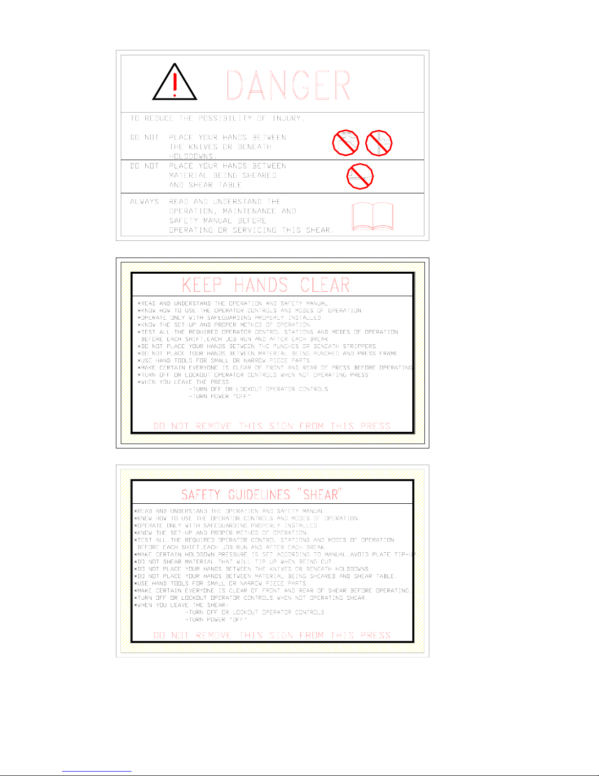
Safety Stickers
Operator should be aware of all stickers located on the machine. Certain
19
Page 25
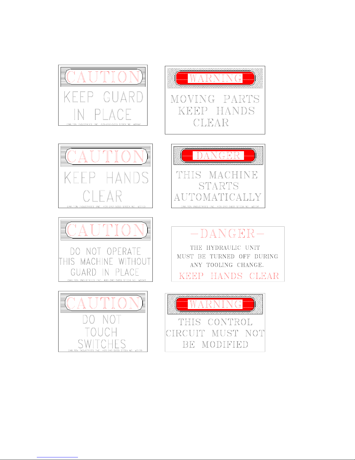
stickers are used on different machines so identify and be familiar with
stickers on your specific machine. Pay special attention to type of sticker and
its location.
20
Page 26
21
Page 27

Infeed/Outfeed Conveyors
a. Gear Reducer: One (1) Radicon® motor/reducer is used on each conveyor.
Recommended lubricants are as follows under applying working conditions:
Ambient Temp Range: 14 to 86°F ------ ISO Visc Grade#: 220
Ambient Temp Range: 32 to 113°F ---- ISO Visc Grade#: 320
Ambient Temp Range: 50 to 122°F ----- ISO Visc Grade#: 460
Mineral Oils
Supplier
Chevron Oil Co. Chevron Gear Compounds EP
Esso Petroleum Co. Spartan EP
Mobil Oil Co. LTD MobilGear 600 Series
Shell LTD Omala
Tribol (ICI) LTD Tribol 1100
Synthetic Oils
Supplier
Chevron Oil Co. Synthetic DBH
Esso Petroleum Co. Spartan SEP
Mobil Oil Co. LTD MobilGear SHC
Shell LTD Hyperia S
Tribol (ICI) LTD Tribol 1510
After an initial operating period of approximately 250 hours, the reducer housing
should be drained, preferably while warm. Refill with approximately 5/8 gallon
(2.4 liters) of fresh oil. Thereafter, change oil at 10,000 hours of operation for
mineral oil and 20,000 hours of operation for synthetic oil.
b. Roller Chain: Inspection on the chain return bearing should be made occasionally
to insure sufficient wear has not accumulated causing the chain to drag against
metal. The chain may be tightened at the Take-Up Bracket located near the
motor/reducer section of the machine. As the drive chain becomes stretched
beyond adjustment, links may be removed from the chain loop. Caution must be
observed to avoid a binding effect between the chain rollers and sprockets. It is
advisable to replace the chain rather than damage the sprockets because the
sprockets are not replaceable without ordering new rollers. Spray with light oil as
needed.
c. Roller Bearings: There are two types of bearings used on the conveyors. One
type contains lifetime lubricated bearings and the rest contain grease fittings in the
end of the hex shafts on each side of the conveyors. For rollers with grease fittings,
ubricate with a lithium base grease approximately once every two-hundred (200)
hours of operation.
Range Name
Range Name
General Maintenance
22
Page 28

Flux Recovery Equipment (on Weld Splice Station & Pull Thru Welder)
a. Filter & Dust Bag: Particular attention should be given the filter or dust bag on
flux recovery equipment. To assure efficiency and performance it is imperative
that the dust bag be manually agitated at regular intervals; at least every eight (8)
hours if the equipment is in continuous operation. To agitate or shake the dust bag
- remove dust tank cover, grasp the steel spider, lift up and shake , then replace
spider in position. This action will dislodge any accumulation of dust and keep the
pores of the filter cloth open. Note: Failure to agitate the dust bag at regular
intervals will result in lack of performance and premature dust bag failure.
After the installation has been properly adjusted, the next step is to determine the
amount of flux fused during a given period, for example; if 100 pounds of flux is
fused during an 8 hour run, 100 pounds of new flux must be added to the primary
tank at this time, thereby assuring ample reserve and prevent a shutdown for
refilling the tank while work is in process. The equipment should be serviced at
regular intervals, for example; at the end of each 8 hour shift:
1> Empty slag screen in primary tank.
Note: The only purpose of the slag screen is to collect such fused particles
that may be recovered from the weld. Do not chip off the slag seam or
attempt to recover slag in volume. To do so will overload the screen, thereby
preventing the unfused flux from passing through the screen. The result will
be excess carry-over of usable material to secondary tank.
2> Refill primary tank, replacing the amount of flux consumed during the past 8
hour run.
3> Agitate the dust bag.
4> In case of dust bag failure, shut down machine and replace at once. DO NOT
OPERATE THE UNIT WITHOUT DUST BAG OR WITH FAULTY DUST
BAG. A discharge of fine, white dust from the exhaust indicates dust bag
failure of that material is being passed through the vacuum producer unit.
Failure to correct immediately will result in expensive repairs.
b. Electric Motor Sleeve Bearing: The bearing sleeve is steel on the outside for
strength with a tin base babbit lining on the inside for low friction and long
wear. The initial factory lubrication is normally adequate for approximately
one year under normal operation. Thereafter, lubricate approximately once
every one thousand (1000) hours of operation. This requires about 3 to 4
squirts from a 4 inch oil can. Use only a light grade minerial oil (similar to
SAE 10W) having a viscosity of 210 sec. at 100° F.
Tack Station
23
Page 29

Stop Gate Arm: The arm pivots on a shaft to allow it to drop out of the way until
needed. At the pivot point there are two (2) grease fittings; one at each end of the
arm. Two (2) grease fittings should be lubricated with a good lithium base grease
approximately once every forty (40) hours of operation.
Pull Through Welder
a. Wire Drive: The Lincoln® brand Wire Drive Gearbox contains gears that should
be recoated with a non-fluid type lubricant (Lincoln Spec. E2322) approximately
once every two-thousand (2000) hours of operation. For access to the gears in one
chamber, remove the adapter plate and motor assembly. To lubricate the gears in
the other chamber, remove one of the pipe plugs and feed grease in contact with
the bevel gear teeth while rotating the output shaft until all teeth are lubricated.
b. Linear Motion Bearings: Eight (8) bearings are used on the welding heads (4 per
welding head). These bearings have a grease fitting in the end that should be
greased with a (No.2) lithium type soap base grease approximately every onethousand (1000) hours of operation.
c. Gear Reducer: Two (2) Winsmith® reducers are used on the drive roller motor.
One is located on the stationary side and one on the moveable side. Recommended
lubricants are as follows under applying working conditions:
Ambient Temp Range: 14 to 86°F ------ ISO Visc Grade#: 220
Ambient Temp Range: 32 to 113°F ---- ISO Visc Grade#: 320
Ambient Temp Range: 50 to 122°F ----- ISO Visc Grade#: 460
After an initial operating period of approximately 250 hours, the housing should be
drained, preferably while warm. Refill to midpoint plug level with fresh oil. Under
normal conditions, the drive should be re-lubricated at intervals of once every twothousand (2000) hours of operation.
d. Roller Chain: Inspection on the drive roller chain should be made occasionally to
insure sufficient wear has not accumulated causing the chain to stretch. As the
drive chain becomes stretched, it may be adjusted by loosing the motor/reducer
mounting
bracket enough to slide the bracket back until chain is tight; then re tighten bracket
5/8-11NC hex bolts to approximately 150 ft/lbs. To reduce friction, spray chain
with light oil as needed.
e. Moveable Arc Base: The moveable arc base contains a bronze bearing at each
corner (4 total) allowing it to slide on two (2) round tubes welded to the lift
carriage frame. The sliding base contains one grease fitting per bearing. There is
one (1) grease fitting in the pivot shaft bearing. A total of five (5) grease fittings
should be lubricated with a lithium base grease approximately once every forty
24
Page 30

(40) hours of operation.
f. Jack Screws & Nuts: The lift carriage frame is horizontally positioned by a total
of four (4) jack screws (1 at each corner of the frame). Each jack screw and each
jack nut contain a grease fitting for lubrication. A total of eight (8) grease fittings
should be lubricated with a lithium base grease approximately once every onehundred sixty (160) hours of operation.
Hydraulic Power Units
Today's hydraulic systems will give many years of trouble free operation when properly
maintained. Studies have shown that over 60% of all hydraulic systems down time can
be attributed to untidy maintenance, and lack of proper filtration. If the hydraulic fluid
becomes contaminated, orifice blockage, valve sticking, internal wear of hydraulic
components, pressure loss, and even pump failure can occur. The following guidelines
are given as minimal requirements under normal shop conditions.
a. Initial Oil Change: Change the hydraulic oil, clean the tank, and replace the return line
filter cartridge after the first two-hundred fifty (250) hours of operation. See tag on
power unit for proper type of hydraulic oil. Various pumps are used on FMI power
units; so see tag for the type of oil used in your particular units.
b. Oil Change Requirements: Replacing system fluid is dependent on several factors
according to the degree of aging or contamination of the oil. Franklin recommends in
the absence of other checks that the oil be changed every 2000 hours of operation for
normal shop conditions. Keep a running check on the oil conditions, take a sample of
the oil and pass it through filter paper or clean cloth. The coloring of the residue will
indicate the degree of aging. If the color is blue/black, an oil change is required
immediately. Old and contaminated oil cannot be improved by topping up with fresh
oil. The used oil should be completely drained while at working temperature and
properly disposed of.
c. Filter Element: The hydraulic filter element must be replaced when dirty. Standard
FMI power units contain a Differential Pressure Indicator. This is simply a gauge on
the filter that indicates pressure buildup on the front side of the element. Check the
Differential Pressure Indicator at least once a week. The element must be replaced
when the Differential Pressure Indicator indicates service is required. The following
steps should be followed when changing a filter element:
1. Lock-out power from the power unit. Check gauges to be certain all pressure is
removed.
2. Remove cover.
3. Remove insert (bridge which holds the element in place).
4. Remove bypass spring assembly from the stud.
5. Remove contaminated cartridge with a twisting motion.
6. Discard disposable element cartridge.
25
Page 31

7. Lubricate all seals.
8. Mount new cartridge. For ease of mounting, hold the cartridge away from the
magnetic core until the stud is through the hole in the bottom of the element. Then
slide it up to securely seat with the top of bridge.
9. Install bypass spring assembly.
10. Re-install insert into filter housing (make sure the top spring is secure).
11. Re-install cover. Torque cover nuts to 35 ft/lbs.
12. Check for and eliminate leaks upon system start-up.
13. Check differential pressure indicator to monitor element condition.
d. Tank Cleaning: The tank should be drained and cleaned approximately every 1000
hours of operation. Be sure to clean and remove any particles in the bottom of the
reservoir. Use lint free rags. Use a filter when re-filling with a mesh width of 0.002"
(0.06MM) or better - fill via 10 micron system filter.
CAUTION: Serious damage will result from excessive hydraulic pressures. High
pressure will not speed cycle times. Alterations in relief valve settings will void all
warranties.
Pneumatic Filters & Lubricators
The filter and lubricator are a part of the SMC Filter-Regulator-Lubricator Combos
that are mounted on the Weld Splice Station and the Pull Thru Welder. This is where
the air lines are connected to the fabricator.
a. Filter Element: Filter elements should be changed after 1 year or when a pressure
drop of 15 PSI (1kgf per square cm) is reached. The safety lockout valves must be
locked in the "OFF" position and pressure removed from system before attempting
to change filters.
b. Lubricators: The Lubricators should be checked daily and refilled as needed.
SMC recommended oil is ISO VG32. A section of the reservoir bowl is
transparent to allow maintenance personnel to view the level of the oil. The
reservoir should be checked approximately once every eight (8) hours and refilled
as needed. To refill, maintenance personnel must:
1> The air pressure must be padlocked in the OFF position.
2> Press the release button indicated by an arrow on the front of the device and
rotate the reservoir bowl 1/4 turn counter clockwise.
3> Remove the bowl and refill with ISO VG32 (or equal) oil. A fill level line is
marked on the side of the bowl to indicate the proper fill level.
4> Secure the reservoir bowl back in place and turn the air back to the ON position
to resume operation.
Bolt Torque Values
The following chart is a list of standard torque values for standard bolts used on most
26
Page 32

FMI equipment. Maintenance from time to time should check the fabricator for loose
bolts, especially parts subjected to severe shock.
Size SAE Grade 5 SAE Grade 8
Clamp
Load
Dry Lbs Wet Lbs Dry
Assembly Torque Clamp
Load
Assembly Torque
Lbs
Wet Lbs
1/4-20 2000 8 Ft 75 In 2850 12 Ft 9 Ft
1/4-28 2300 10 Ft 86 In 3250 14 Ft 10 Ft
5/16-18 3350 17 Ft 13 Ft 4700 25 Ft 18 Ft
5/16-24 3700 19 14 5200 25 20
3/8-16 4950 30 23 7000 45 35
3/8-24 5600 35 25 7900 50 35
7/16-14 6800 50 35 9550 70 55
7/16-20 7600 55 40 10650 80 60
1/2-13 9000 75 55 12750 110 80
1/2-20 10250 90 65 14375 120 90
9/16-12 11600 110 80 16375 150 110
9/16-18 13000 120 90 18250 170 130
5/8-11 14400 150 110 20350 220 170
5/8-18 16375 180 130 23000 240 180
3/4-10 21300 260 200 30100 380 280
3/4-16 23800 300 220 33500 420 320
7/8-9 29450 430 320 41600 600 460
7/8-14 32450 470 360 45900 660 500
1-8 38600 640 480 54500 900 680
1-12 42300 710 530 59700 1000 740
1-14 43400 730 540 61200 1020 760
1 1/8-7 42300 800 600 68900 1280 960
1 1/8-12 47500 880 660 77000 1440 1080
1 1/4-7 53800 1120 840 87200 1820 1360
1 1/4-11 59600 1240 920 96600 2000 1500
Note: All torque load values are in Foot Pounds except those noted otherwise. 1/4"
Bolts - Grade 5 ONLY are shown in Inch Pounds.
Summary of Maintenance Intervals
27
Page 33

The schedules listed are for a standard 40 hour work week
Once every eight (8) hours of operation = Daily
1> Flux Recovery Equipment
a. Empty slag screen in primary tank
b. Refill primary tank
c. Agitate dust bag
2> Pneumatic Lubricators (check oil level)
Once every forty (40) hours of operation = Weekly
1> Tack Station - Stop Gate Arms (grease)
2> Pull Thru Welder - Moveable Arc Base (grease)
3> Hydraulic Power Unit
a. Check differential pressure indicator on filter
b. Check oil level
Once every eighty (80) hours of operation = 2 Weeks
1> Check Chain Tension On Chain Driven Equipment
Once every two-hundred (200) hours of operation = 5 Weeks ≈ Monthly
1> Pull Thru Welder: Jack Screws & Nuts (grease)
2> Hydraulic Power Unit (check oil conditions)
3> Conveyor Roller Bearings (grease)
Once every six-hundred (600) hours of operation = 15 Weeks ≈ 3 Months
1> Check all bolts subjected to shock (condition and torque)
Once every one-thousand (1000) hours of operation = 25 Weeks ≈ 6 Months
1> Pull Thru Welder Heads - Linear Bearings (grease)
2> Hydraulic Power Unit (clean tank; filter or change oil)
3> Flux Recovery System - Electric Motor Sleeve Bearing
(3 or 4 squirts from oil can using a light mineral oil)
Once every two-thousand (2000) hours of operation = 50 Weeks ≈ Yearly
1> Pull Thru Welder Wire Drive Gear Reducers (change gear oil)
2> Hydraulic Power Unit (change hydraulic oil & clean tank)
3> Pneumatic Line Filters (change filter)
Once every ten-thousand (10,000) hours of operation = 250 Weeks ≈ 5 Years
1> Conveyors: Radicon® Gear Reducers (change gear oil)
Once every twenty-thousand (20,000) hours of operation = 500 Weeks ≈ 10 Years
1> Hydraulic Power Unit & Flux Recovery: Electric Motor Ball Bearings (grease)
28
Page 34

Section #2: Assembly & Parts List
Our equipment is designed for the maximum life possible for any given application.
However, all fabricators have many moving parts that will eventually cause some wear over
the lifetime of the equipment. This manual is developed to help the customer order
replacement parts if needed. Enclosed are several assembly drawings that list the various
sections of the fabricator. All drawings in this manual are in order as listed on the contents
page.
First, understand what the fabricator does that contains the part you need. Scan the
contents page until you find the appropriate assembly drawing(s). Find the drawing number
located to the left of the drawing name. Turn to the drawing. The drawing numbers are
located on the lower left hand side of each folded drawing.
When you find the assembly drawing you need, take the drawing out of the binder
and unfold it. A general assembly will be shown. Find the replacement part that you will
need. Each individual part on the drawing should have a number or letters indicating where
to look on the "Bill of Materials". The Bill of Materials will be listed in the upper right hand
corner of the drawing after it has been unfolded. Find the numbers in the Bill of Materials
under "Detail Mark" that corresponds to the part you need.
Try to find either a 6 digit part number (example: 790505) or a detail drawing number
(example: Dwg# F1956-A4-17). One or both should be listed beside the Detail Mark in the
Bill of Materials. Next, you will need the serial number of the machine. Call Franklin at
(256) 332-6654, and give our salesman the serial number of the machine, part number and/or
detail drawing number. We will deliver the part as soon as possible. Franklin has a large
inventory of many stock items that can be shipped out the same day as your order. If the part
is not in stock, we will ship the part as soon as possible.
If for some reason the part is not listed or can not be found, our salesmen will work
with you to find the part you need. Sometimes the drawing you are looking for may not be
apparent and all relating assembly drawings may need to be viewed. If a part number or
detail drawing isn't found, the salesman will need the serial number of the machine, a detail
description of where the part was located, what it looks like, and what it does. This
procedure will help save the customer and FMI lost time and money because of sending
wrong machine parts.
All parts used on our machinery are designed to be of the highest quality possible to
ensure the maximum life for all our machines. We strive to make our equipment
the best using quality parts so we can be proud to say, Made in the USA..
29
Page 35

F3138 (PTW-72 Horizontal Welding System)
F3138-00 (PTW-72 Horizontal Welding System)
842385 (Conveyor Assembly)
842260 (Take Up Sub Assembly)
818100 (Seam Welder Assembly)
818101 (Main Frame Pivot Assembly)
818004 (Flux Box Assembly)
818001 (Seam Welder Platform Assembly)
818007 (Support Platform for Pull Through Welder)
842372 (Infeed Conveyor Assembly)
842451 (Datum Roller Assembly)
F3110-C842 (25’ Powered Conveyor)
F2992-R842 (Take Up Assembly)
F3110-F842 (Pivot Cylinder Mount)
F2992-E842 (Carriage Assembly w/ Drive)
F2992-K842 (Carriage Assembly w/o Drive)
F3110-E842 (25’ Up Ender)
F3110-B842 (25’ Powered Conveyor)
F2992-C842 (25’ Stationary Up Ender Assembly)
F2992-E842 (Carriage Assembly w/ Drive)
F2992-K842 (Carriage Assembly w/o Drive)
F3110-F842 (Pivot Cylinder Mount)
819140 (Lift Gate Tack Station)
819150 (72” Material Tack Weld Station)
819002 (Web Lift Carriage)
819003 (Drive End Assembly Station)
819004 (Web Lift Undercarriage Assembly)
819105 (72” Main Frame Assembly)
819151 (Flange Carriage Assembly)
819153 (Datum Roller Assembly)
819001 (Flange Clamp Assembly)
819155 (Gate Stop Assembly)
819175 (Magnet Slide)
842386 (30’ Powered Outfeed Conveyor)
842260 (Take Up Sub Assembly)
Page 36

842344 (30’ Web-Lift Infeed Conveyor)
842260 (Take Up Sub Assembly)
845301 (Front Web Lifter)
819600 (72” Material PTW Assembly)
819608 (Intermediate Web Support Roller Assembly)
819585 (Wire Spool Turntable)
819300 (Main Frame Assembly)
819315 (Vacuum & Recovery Tank Mtg.)
819332 (Horizontal Infeed Roller Assembly)
819601 (Carriage Lift Assembly w/ Tilt)
819425 (Infeed Web Lift Assembly)
819430 (Infeed Web Lift Assembly)
819487 (Flux Holder Assembly on Stationary Side)
819488 (Flux Holder Assembly on Moveable Side)
819489 (Encoder Mounting Assembly)
819604 (Web Support Bracket)
819360 (Welding Head Assembly)
819395 (Stationary Drive Wheel & Ground Assembly)
819602 (Stationary Side Copper Wheel Assembly)
819603 (Moveable Side Copper Wheel Assembly)
819607 (Drive Wheel Assembly)
819385 (Moveable Side Grounding Shoe Assembly)
819476 (72” PTW Extension Assembly)
F3110-G842 (Conveyor Assembly)
F3110-A830 (De-Camber Pusher)
F3110-B830 (Slide Extension)
F3110-E830 (Cylinder Slide Assembly)
F3110-J842 (8’-6” Conveyor Extension)
842366 (30’ Non-Powered Conveyor)
842325 (Splice Take Up Assembly)
842346 (30’ Powered Conveyor)
Page 37

Page 38

Page 39

Page 40

Page 41

Page 42

Page 43

Page 44

Page 45

Page 46

Page 47

DETAIL A
SCALE 1 / 10
DETAIL B
SCALE 1 / 10
SECTION C-C
SCALE 0.06 : 1
1
1
2
2
3
3
4
4
5
5
6
6
7
7
8
8
A A
B B
C C
D D
DRAWN
APPROVED
DATE
DATE
ENGINEER DATE
FILENAME
REV
Franklin Manufacturing Company, Inc.
FMI
THIS PRINT IS THE PROPERTY OF FMI, INC. AND MUST BE RETURNED UPON DEMAND. THE POSSESSION AND INFORMATION THEREON OF THIS DRAWING
DOES NOT GRANT ANY RIGHTS REGARDING REPRODUCTION, MANUFACTURING, OR THIRD PARTY RIGHTS WITHOUT WRIT T E N PERMISSION OF FMI, INC.
SIZE
SCALE
DWG NO REV
For
BYDATEZONE DESCRIPTION
SIMILAR TO: SUPERSEDES: OPPOSITE HAND:
FINISH SYMBOL
HONE
POLISH
GRIND
FINE
SEMI-FINE
MEDIUM
SEMI-ROUGH
ROUGH
8
16
32
63
125
250
500
1000
STANDARD TOLERANCES UNLESS OTHERWISE NOTED
MACHINE TOLERANCES
1. x.xx = +/- 0.01
2. x.xxx = +/- 0.002
3. x.xxxx = +/- 0.0005
4. x / xx = +/- 1/64
5. xx
° = +/- 1/2 deg
FABRICATION TOLERANCES
1. WELDMENTS 0" >< 2'-0" = +/- 1/32
2. WELDMENTS 2'-0" >< 10'-0" = +/- 1/16
3. WELDMENTS 10'-0" >< 30'- 0" = +/- 3/32
4. WELDMENTS 30'-0" >< 60'-0" = +/- 1/8
1. DO NOT SCALE DIMENSIONS. 4. ALL DIMENSIONS ARE IN INCHES U.N.O.
2. BREAK SHARP CORNERS. 5. REFERENCE DIMENSIONS SHOWN AS (xx).
3. REMOVE ALL BURRS.
15825 Hwy. 243 - Russellville, AL 35653
Phone (256) 332-6654
Fax (256) 332-0143 www.FMI-Solution s.com
Sheet of Last Saved on
WEIGHT
3/28/2005
KArthur
5/21/2003
C:\Engineering\Drawings\FMI Jobs\3100-3199\3110\F3110-C842.idw
D3:50
F3110-C842
25' Powered Conveyor
Flange Up-Ender
SOsborn
1 1
Jan-5-06
5983.2 lbmass
THIRD ANGLE
MATERIAL LIST
ITE PART NUMBER QTY TITLE COMMENTS
1 (Ref. Only) 10 1/2-13UNC x 6" Lg. Anchor Bolt BLT050-13600ANGR5
2 836080 7 I dle r Sprocket Spacer
3 840021 10 Leg Clip
4
840037 1 Idler Sprocket Guard
5 BF 0.19x01.00-UHMW 1 Chain Return Wear Strip (19'-8" Total Length)
6 BLT025-20050BHGR8 12 Button Head, Hex, 1/4-20 UNC
x 1/2 Lg
7
BLT050-13125HHGR5 34 Hex Cap 1/2-13 UNC x 1 1/4 Lg
8 BLT050-13150HHGR5 32 Hex Cap 1/2-13 UNC x 1 1/2 Lg
9 BLT050-13200HHGR5 12 Hex Cap 1/2-13 UNC x 2 Lg
10 BLT050-13250HHGR5 8 H ex Cap 1/2-13 UNC x 2 1/2 Lg
11 BLT063-11250HHGR57Hex Cap 5/8-11 UNC x 2 1/2 Lg
12 BLTN10-24050BHGR8 6 Button Head, Hex, 10-24 UNC x
1/2 Lg
13 BRBRNZ125150100FB 6 Bo ston Flanged Bushing,
Sintered Bronze, FB2024-8: Ø1
1/4 ID x Ø1 1/2 OD x 1 Lg.
14 CHAIN-060 82ft RC-60 ROLLER CHAIN
15 CHAIN-060-CLINK 1 CONNECTING LINK
16
CHAIN-060-OLINK
2
OFFSET LINK
17 F2992-01_mir 1 25' Infeed Conveyor Weldment
18 F2992-10 16 Conveyor Powered Rolle r
19 F2992-11 1 Conveyor Powered Roller
20 F2992-15 3
Carriage Rail
21 F2992-16 3 Pivot Bracket
22 F2992-20 1 Chain Accesss Door Pattern
23 F2992-21 4 Chain Tensioning Block
24 F2992-22 4
Chain Adjusting Bolt
25 F2992-33 3 Pivot Bracket
26 F2992-36 3 Pivot Shaft
27 F2992-56_mir 1 Chain Guard #2 (opp hand)
28 F2992-57_mir 1
Chain Guard #4 (opp hand)
29 F2992-62_mir 1 Chain Guard (Opp. Hand)
30 F2992-71 2 UpEnder Tie Plate Pattern
31 F2992-E842 2 Carriage Assembly with Drive
32 F2992-K842 1
Carriage Assembly w/o Drive
33 F2992-R842 1 Take-Up Assembly
34 F3110-18_mir 1 Chain Guard (opp hand)
35 F3110-24 1 Chain Guard
36 F3110-E842 1 25' Up-Ender
37 F3110-E842_mir 1 F3110-E842 (opp hand)
38 F3110-F842 3 Pivot Cylinder Mount
39 NUT050-13HEXGR5 56 Hex Nut 1/2-13 UNC
40
NUT063-11HEXGR5
15
Hex Nut 5/8-11 UNC
41 SPKT-060-013-I
7
Dodge #60 Idler Sproc ke t
42 WSH050-FLAT 33 Ø1/2 Flat Washer, USS
43 WSH050-LOCK 88
Ø1/2 LockWasher
44
WSH063-LOCK
7
Ø5/8 LockWasher
A
B
#
Parent
Level
Required
CC
FLOW
34 56
60 60 60 30
93 B.F.
60 5/8
106 1/2
20
18
31
20
21
1326
37
18
28
19
37
19
15 3/4 123 1/8 115 5/8 60 1/2
1
0
0
1
1
/
3
2
300
18
36
31 14 16
20
21
38
32
20
4
17
38
17
36
4
4
7
/
8
37
28
31
20
21
26
13
13
3825
36
31
20
17
20
21
38
19141516
10 17/32
DATUM
4
3
0
P
A
S
S
H
E
I
G
H
T
38
32
17
37
28
29
2734
26
26
21
21
21
25
18
37
38
3
8424322
8394243
22
3 1
23 24 40
10 39 43
411140244
5
3073943
1 1/32
DRILL n#7-0.201 THRU
TAP 1/4-20UNC THRU
(12 TOTAL @ ASSEMBLY)
6
DRILL n#25 - 0150 THRU
TAP #10-24UNC THRU
LOCATE & TAP @ ASSEMBLY
(6 TOTAL)
12
37 Feet min.
37
39743
3
8 42 43 39
8424339
8 43
9 42 43 39
33
30
37
35
Page 48

Page 49

1
1
2
2
3
3
4
4
A A
B B
DRAWN
APPROVED
DATE
DATE
ENGINEER DATE
FILENAME
REV
Franklin Manufacturi ng Co mpany, Inc.
FMI
THIS PRINT IS THE PROPERTY OF FMI, INC. AND MUST BE RETURNED UPON DEMAND. THE POSSESSION AND INFORMATION THEREON OF THIS DRAWING
DOES NOT GRANT ANY RIGHTS REGARDING REPRODUCTION, MANUF ACTURING, OR THIRD PARTY RIGHTS WITHOUT WRITTEN PERMISSION OF FMI, IN C.
SIZE
SCALE
DWG NO REV
For
BYDATEZONE DESCRIPTION
SIMILAR TO: SUPERSEDES: OPPOSITE HAND:
FINISH SYMBOL
HONE
POLISH
GRIND
FINE
SEMI-FINE
MEDIUM
SEMI-ROUGH
ROUGH
8
16
32
63
125
250
500
1000
STANDARD TOLERANCES UNLESS OTHERWISE NOTED
MACHINE TOLERANCES
1. x.xx = +/- 0.01
2. x.xxx = +/- 0.002
3. x.xxxx = +/- 0.0005
4. x / xx = +/- 1/64
5. xx
° = +/- 1/2 deg
FABRICATION TOLERANCES
1. WELDMENTS 0" >< 2'-0" = +/- 1/32
2. WELDMENTS 2'-0" >< 10'-0" = +/- 1/16
3. WELDMENTS 10'-0" >< 30'-0" = +/- 3/32
4. WELDMENTS 30'-0" >< 60'-0" = +/- 1/8
1. DO NOT SCALE DIMENSIONS. 4. ALL DIMENSIONS ARE IN INCHES U.N.O.
2. BREAK SHARP CORNERS. 5. REFERENCE DIMENSIONS SHOW N AS (xx).
3. REMOVE ALL BURRS.
15825 Hwy. 243 - Russellville, AL 35653
Phone (256) 332-6654
Fax (256) 332-0143 www.FMI-Solutions.com
Sheet
of
Last Saved on
WEIGHT
3/24/2005
KArthur
1/25/2005
C:\Engineering\Drawings\FMI Jobs\3100-3199\3110\F3110-F842.idw
B
23:100
F3110-F842
Pivot Cylinder Mount
Flange Up-Ender Conveyor
SOsborn
1 1
Jan-5-06
56.3 lbmass
THIRD ANGLE
MATERIAL LIST
ITE PART NUMBER QTY TITLE COMMENTS
1
BLT050-13150SHGR8
4
SHCS 1/2-13 UNC x 1 1/2 Lg
2 BRBRNZ100125075FB 2 Boston Flanged Bushing,
Sintered Bronze, FB1620-6: Ø1
ID x Ø1 1/4 OD x 3/4 Lg.
Boston Gear oil impregnated, flanged series
bronze bushings
"Bost-Bronz" series pg 14-1 5
3
CLMARC100100-16-SH
1
Rod Clevis Same as TJ# S-662-10
4 F3110-20 1
Cylinder Pivot
5 F3110-21 1
Side Plate
Pattern
6
NUT100-14JAMGR5
1
Hex Jam Nut 1-14 UNS
7
VICKTF17EDLA3AA10200
1
Ø2.5 Bore x 10.13 Stroke
Cylinder
Rear Cushion
#
Parent
Level
Required
3
4
6
7
1
1
5
7
4
3
6
7
1
4
1
1
4
5
7
4
3
8
3
/
8
2
0
1
3
/
3
2
3 9/32
91.90°
7
7
2
Page 50

Page 51

Page 52

1
1
2
2
3
3
4
4
5
5
6
6
7
7
8
8
A A
B B
C C
D D
DRAWN
APPROVED
DATE
DATE
ENGINEER DATE
FILENAME
REV
Franklin Manufacturi ng Company, Inc.
FMI
THIS PRINT IS THE PROPERTY OF FMI, INC. AND MUST BE RETURNED UPON DEMAND. THE POSSESSION AND INFORMATION THEREON OF THIS DRAWING
DOES NOT GRANT ANY RIGHTS REGARD ING REPRODUCTION, MANUFACTUR ING, OR THIRD PARTY RIGHTS WITHOUT WRI TT EN PERMISSION OF FMI, INC.
SIZE
SCALE DWG NO REV
For
BYDATEZONE DESCRIPTION
SIMILAR TO: SUPERSEDES: OPPOSITE HAND:
FINISH SYMBOL
HONE
POLISH
GRIND
FINE
SEMI-FINE
MEDIUM
SEMI-ROUGH
ROUGH
8
16
32
63
125
250
500
1000
STANDARD TOLERANCES UNLESS OTH E R WISE NOTED
MACHINE TOLER ANCES
1. x.xx = +/- 0.01
2. x.xxx = +/- 0.002
3. x.xxxx = +/- 0.0005
4. x / xx = +/- 1/64
5. xx
° = +/- 1/2 deg
FABRICATION TOLERANCES
1. WELDMENTS 0" >< 2'-0" = +/- 1/32
2. WELDMENTS 2'-0" >< 10'-0" = +/- 1/16
3. WELDMENTS 10'-0" >< 30'-0" = +/- 3/32
4. WELDMENTS 30'-0" >< 60'-0" = +/- 1/8
1. DO NOT SCALE DIMENSIONS. 4. ALL DIMENSIONS ARE IN INCHES U.N.O.
2. BREAK SHARP CORNERS. 5. REFERENCE DIMENSIONS SHOWN AS (xx).
3. REMOVE ALL BURRS.
15825 Hwy. 243 - Russellville, AL 35653
Phone (256) 332-6654
Fax (256) 332-0143 www.FMI-Solutions.com
Sheet
of
Last Saved on
WEIGHT
3/25/2005
KArthur
1/19/2005
C:\Engineering\Drawings\FMI Jobs\3100-3199\3110\F3110-E842.idw
D
3:25
F3110-E842
25' Up-Ender
Stationary Side
SOsborn
1 1
Jan-5-06
666.3 lbmass
THIRD ANGLE
MATERIAL LIST
ITE PART NUMBER QTY TITLE COMMENTS
1 F2992-P842 1 Up-Ender 2nd Section
2 F2992-D842 1 Up-Ender 1st Section
3 F2992-30 1 Drive End Pivot Arm
4 F2992-31 2 Pivot Arm
5 CHAIN-060 38 ft RC-60 Roller Chain
6 CHAIN-060-CLINK 1 Chain Connecting Link
7 CHAIN-060-OLINK 1 Chain Offset Link
#
Parent
Level
Required
3/4
15 11/16 28 33 62 1/8 57 1/4 43 7/16
3/4
3
2
4
1
4
3
2
3/4
24 11/16
32 1/2 36 1/2 52 3/8
28 11/16
3/4
22 15/16
34 1/2 36 1/4 21 3/16 3/4
239 1/2
12 7/8
1
8
1
/
4
3
2
1
4
4
Page 53

DETAIL A
SCALE 1 / 10
DETAIL B
SCALE 1 / 10
SECTION C-C
SCALE 0.06 : 1
DETAIL OF MOTOR
SCALE 0.12 : 1
SECTION F-F
SCALE 0.06 : 1
1
1
2
2
3
3
4
4
5
5
6
6
7
7
8
8
A A
B B
C C
D D
DRAWN
APPROVED
DATE
DATE
ENGINEER DATE
FILENAME
REV
Franklin Manufacturing Company, Inc.
FMI
THIS PRINT IS THE PROPERTY OF FMI, INC. AND MUST BE RETURNED UPON DEMAND. THE POSSESSION AND INFORMATION THEREON OF THIS DRAWING
DOES NOT GRANT ANY RIGHTS REGARDING REPRODUCTION, MANUFACTURING, OR THIRD PARTY RIGHTS WITHOUT WRITTE N PERMISSION OF FMI, INC.
SIZE
SCALE
DWG NO REV
For
BYDATEZONE DESCRIPTION
SIMILAR TO: SUPERSEDES: OPPOSITE HAND:
FINISH SYMBOL
HONE
POLISH
GRIND
FINE
SEMI-FINE
MEDIUM
SEMI-ROUGH
ROUGH
8
16
32
63
125
250
500
1000
STANDARD TOLERANCES UNLESS OTHERWISE NOTED
MACHINE TOLERANCES
1. x.xx = +/- 0.01
2. x.xxx = +/- 0.002
3. x.xxxx = +/- 0.0005
4. x / xx = +/- 1/64
5. xx
° = +/- 1/2 deg
FABRICATION TOLERANCES
1. WELDMENTS 0" >< 2'-0" = +/- 1/32
2. WELDMENTS 2'-0" >< 10'-0" = +/- 1/16
3. WELDMENTS 10'-0" >< 30'- 0" = +/- 3/32
4. WELDMENTS 30'-0" >< 60'-0" = +/- 1/8
1. DO NOT SCALE DIMENSIONS. 4. ALL DIMENSIONS ARE IN INCHES U.N.O.
2. BREAK SHARP CORNERS. 5. REFERENCE DIMENSIONS SHOWN AS (xx).
3. REMOVE ALL BURRS.
15825 Hwy. 243 - Russellville, AL 35653
Phone (256) 332-6654
Fax (256) 332-0143 www.FMI-Solution s.com
Sheet of Last Saved on
WEIGHT
3/24/2005
KArthur
5/21/2003
C:\Engineering\Drawings\FMI Jobs\3100-3199\3110\F3110-B842.idw
D3:50
F3110-B842
a
25' Powered Conveyor
Flange Up-Ender
SOsborn
1 1
Jan-5-06
6387.2 lbmass
THIRD ANGLE
MATERIAL LIST
ITE PART NUMBER QTY TITLE COMMENTS
1 (Ref Only) 1 5 HP 1750 RPM TECF
1450-184-TC
LEESON# 131508
2 (Ref. Only) 10 1/2-13UNC x 6" Lg. Anchor Bolt BLT050-13600ANGR5
3 836080 8 Idle r Sprocket Spac er HR 10 18
4 840021 10 Leg Clip
5 840037 1 Idler Sprocket Guard
6 BF 0.19x01.00-UHMW 1 Chain Return Wear Strip 19'-8" Total Length
7
BLT050-13125HHGR5 34 Hex Cap 1/2-13 UNC x 1 1/4 Lg
8 BLT050-13150HHGR5 36 Hex Cap 1/2-13 UNC x 1 1/2 Lg
9 BLT050-13200HHGR5 12 Hex Cap 1/2-13 UNC x 2 Lg
10 BLT050-13250HHGR5 8 Hex Cap 1/2-13 UNC x 2 1/2 L g
11 BLT063-11250HHGR57Hex Cap 5/8-11 UNC x 2 1/2 Lg
12 BLT063-11275HHGR5 1 Hex Cap 5/8-11 UNC x 2 3/4 L g
13 BLT075-10275HHGR5 4 Hex Cap 3/4-10 UNC x 2 3/4 L g
14 BRBRNZ125150100FB 6 Boston Flanged Bushing,
Sintered Bronze, FB2024-8: Ø1
1/4 ID x Ø1 1/2 OD x 1 Lg.
15 BSH-2012-163-TL 1 DODG #117092 2012 Bushing,
1.63 Bore
16
CHAIN-060 82ft RC-60 Roller Chain
17 CHAIN-060-CLINK 1 Connecting Link
18 CHAIN-060-OLINK 2 Offset Link
19 F2992-01_mir 1 25' Infeed Conveyor Weldment
20 F2992-10 16
Conveyor Powered Rol ler
21 F2992-11 1 Conveyor Powered Roller
22 F2992-15 3 Carriage Rail
23 F2992-16 3 Pivot Bracket
24 F2992-20 1
Chain Accesss Door
Pattern
25 F2992-21 4 Chain Tensioning Block
26 F2992-22 4 Chain Adjusting Bolt
27 F2992-33 6 Pivot Bracket
28 F2992-36 3
Pivot Shaft
29 F2992-56_mir 1 Chain Guard #2 (opp hand)
30 F2992-57_mir 1 Chain Guard #4 (opp hand)
31 F2992-61_mir 1 Chain Guard #1 (opp hand)
32 F2992-62_mir 1
Chain Guard (Opp. Hand)
33 F2992-63_mir 1 Chain Guard (opp hand)
34 F2992-71 2 UpEnder Tie Plate Pattern
35 F2992-C842 1 25' Up-Ender
36
F2992-C842_mir
1
25' Up Ender (opp hand)
37 F2992-E842 2 Carriage Assembly with Drive
38 F2992-K842 1 Carriage Assembly w/o Drive
39 F2992-R842 1 Take-Up Assembly
40 F3110-F842 3
Pivot Cylind er Mount
41 NUT050-13HEXGR5 56 Hex Nut 1/2-13 UNC
42 NUT063-11HEXGR5 16 Hex Nut 5/8-11 UNC
43 NUT075-10HEXGR5 4 Hex Nut 3/4-10 UNC
44 RED-M072032BANT1 1
Radicon Reducer 32:1, 184TC
Input
45 SPKT-6 013I 8 Dodge #60 Idler Sp rocket
46 SPKT-6020-TL 1 20 Teeth 60 Series TL Sprocket
for 2012 Bushing
47 WSH050-FLAT 32 Ø1/2 Flat Washer, USS
48 WSH050 - L O CK 90 Ø1 / 2 LockWasher
49 WSH063-FLAT 1
Ø5/8 Flat Washer, USS
50
WSH063-LOCK
8
Ø5/8 LockWasher
51 WSH075 - L O CK 4 Ø3/4 Loc kW asher
#
Parent
Level
Required
A
B
CC
FLOW
F
F
4
4
2
5
/
3
2
34 56 60 60 60 30
1
0
0
1
1
/
3
2
15 11/16
123 3/16 115 5/8 60 1/2
93 BF
68 21/32
106 1/2
3
0
P
A
S
S
H
E
I
G
H
T
300
315
10 17/32
DATUM
36
1 1/16
2 5/16
2814
23
22
6
24
40
21
33
30
36
28
14
14
23
4027
22
37
41 10 48
25 26 42
4534912
841484
19
45
504211
36
20
35
22
37
22
34
38
35
19
37 16 18
35
23
40
2814
24
4 2
5
33
30
29
31
33
4
32
7
48
20161718
8474841
37 Feet Min.
DRILL n#25 - 0150 THRU
TAP #10-24UNC THRU
LOCATE & TAP @ ASSEMBLY
(6 TOTAL)
DRILL n#7-0.201 THRU
TAP 1/4-20UNC THRU
(12 TOTAL @ ASSEMBLY)
40
94748 41
35
37
36
23
24
19
39
36
36
34
24
46 15
13 51 43
1
44
44
40
2 5/8
SET DATUM ROLLER 1/4"
ABOVE CONVEYOR ROLLER
Page 54

Page 55

Page 56

Page 57

1
1
2
2
3
3
4
4
A A
B B
DRAWN
APPROVED
DATE
DATE
ENGINEER DATE
FILENAME
REV
Franklin Manufacturi ng Co mpany, Inc.
FMI
THIS PRINT IS THE PROPERTY OF FMI, INC. AND MUST BE RETURNED UPON DEMAND. THE POSSESSION AND INFORMATION THEREON OF THIS DRAWING
DOES NOT GRANT ANY RIGHTS REGARDING REPRODUCTION, MANUF ACTURING, OR THIRD PARTY RIGHTS WITHOUT WRITTEN PERMISSION OF FMI, IN C.
SIZE
SCALE
DWG NO REV
For
BYDATEZONE DESCRIPTION
SIMILAR TO: SUPERSEDES: OPPOSITE HAND:
FINISH SYMBOL
HONE
POLISH
GRIND
FINE
SEMI-FINE
MEDIUM
SEMI-ROUGH
ROUGH
8
16
32
63
125
250
500
1000
STANDARD TOLERANCES UNLESS OTHERWISE NOTED
MACHINE TOLERANCES
1. x.xx = +/- 0.01"
2. x.xxx = +/- 0.002"
3. x.xxxx = +/- 0.0005"
4. x / xx = +/- 1/64"
5. xx
° = +/- 1/2 deg
FABRICATION TOLERANCES
1. WELDMENTS 0" >< 2'-0" = +/- 1/32"
2. WELDMENTS 2'-0" >< 10'-0" = +/- 1/16"
3. WELDMENTS 10'-0" >< 30'-0" = +/- 3/32"
4. WELDMENTS 30'-0" >< 60'-0" = +/- 1/8"
GENERAL NOTES
1. DO NOT WORK TO SCALED DIMENSIONS, REF ONLY 3. REMOVE A LL BUR RS
2. CLEAN ALL PARTS COMPLETELY PRIOR TO DELIVERY 4. BREAK SHARP CORNERS
15825 Hiway 243 - Russellville, AL 35653
Phone (256) 332-6654
Fax (256) 332-0143 www.FMI-Solutions.com
Sheet
of
Last Saved on
WEIGHT
1/10/2005
KArthur
12/16/2002
C:\Engineering\Drawings\FMIPN\819000 to 819399\819002.idw
B
3:20
819002
a
Web Lift Carriage
SDefoor
1 1
Mar-10-06
91.4 lbmass
MATERIAL LIST
ITE PART NUMBER QTY TITLE
1819031 1
Camroll Shaft
2819037 1
Web Lift Carriage Lift Arm
3819038 1
Web Lift Carriage Base
4
BLT025-20050SSGR8
2
SHSS 1/4-20 UNC x 1/2 Lg
5
BLT050-13175HHGR5
4
Hex Bolt 1/2-13 UNC x 1 3/4 Lg
6
CR-300-S
1
Camroller, 3" Dia
7
NUT050-13HEXGR5
4
Hex Nut 1/2-13 UNC
8
Sagn# 4717
4
Saginaw Trolley Wheel
9
WSH050-LOCK
4
Ø1/2 LockWasher
#
Parent
Level
Required
A 09/14/05
AJH
PART #SAGN4717 WAS SAGN 10366
22
4
2
1
4
7
/
8
1
1
7
/
8
9
1
3
/
1
6
22
3
1
3
/
3
2
3
6
18
12 1/2
9 13/16
1
5
5
/
3
2
1
3
2
1
/
3
2
3
9
2
8
4
1
6
ASSY. NOTE:
After Assy. it May be Nece ssary
to Remove Slack from the Base in
Order to Adjust for Pass Height
Page 58

Page 59

Page 60

Page 61

Page 62

Page 63

Page 64

Page 65

Page 66

Page 67

Page 68

Page 69

Page 70

Page 71

1
1
2
2
3
3
4
4
A A
B B
DRAWN
APPROVED
DATE
DATE
ENGINEER DATE
FILENAME
REV
Franklin Manufacturi ng Co mpany, Inc.
FMI
THIS PRINT IS THE PROPERTY OF FMI, INC. AND MUST BE RETURNED UPON DEMAND. THE POSSESSION AND INFORMATION THEREON OF THIS DRAWING
DOES NOT GRANT ANY RIGHTS REGARDING REPRODUCTION, MANUF ACTURING, OR THIRD PARTY RIGHTS WITHOUT WRITTEN PERMISSION OF FM I, IN C.
SIZE
SCALE
DWG NO REV
For
BYDATEZONE DESCRIPTION
SIMILAR TO: SUPERSEDES: OPPOSITE HAND:
FINISH SYMBOL
HONE
POLISH
GRIND
FINE
SEMI-FINE
MEDIUM
SEMI-ROUGH
ROUGH
8
16
32
63
125
250
500
1000
STANDARD TOLERANCES UNLESS OTHERWISE NOTED
MACHINE TOLERANCES
1. x.xx = +/- 0.01"
2. x.xxx = +/- 0.002"
3. x.xxxx = +/- 0.0005"
4. x / xx = +/- 1/64"
5. xx
° = +/- 1/2 deg
FABRICATION TOLERANCES
1. WELDMENTS 0" >< 2'-0" = +/- 1/32"
2. WELDMENTS 2'-0" >< 10'-0" = +/- 1/16"
3. WELDMENTS 10'-0" >< 30'-0" = +/- 3/32"
4. WELDMENTS 30'-0" >< 60'-0" = +/- 1/8"
GENERAL NOTES
1. DO NOT WORK TO SCALED DIMENSIONS, REF ONLY 3. REMOVE A LL BUR RS
2. CLEAN ALL PARTS COMPLETELY PRIOR TO DELIVERY 4. BREAK SHARP CORNERS
15825 Hiway 243 - Russellville, AL 35653
Phone (256) 332-6654
Fax (256) 332-0143 www.FMI-Solutions.com
Sheet
of
Last Saved on
WEIGHT
1/31/2005
Kirk Arthur
1/28/2005
C:\Engineering\Drawings\FMIPN\819400 to 819999\819585.idw
B
1:8
819585
Wire Spool Turntable
1000 lb Drums
F2679-A4
JLovett
1 1
Mar-10-06
100.7 lbmass
MATERIAL LIST
ITE PART NUMBER QTY TITLE COMMENTS
1 819586 1 Base Weldment
2 819588 1 Brake Adjusting Bolt
3 819590 1 Brake Pad Mounting Plate
4 819589 1 Drum Brake Pad
5 819587 1
Drum Support
6
BLT063-11100HHGR5
2
Hex Cap 5/8-11 UNC x 1 Lg
7
BLT063-11175HHGR5
2
Hex Cap 5/8-11 UNC x 1 3/4 Lg
8
NUT075-10JAMGR5
3
Hex Jam Nut 3/4-10 UNC
9
NUT063-11HEXGR5
2
Hex Nut 5/8-11 UNC
10
Lee# LC-072L-6
1
Lee Compressi on Spring
11
PTI #UCFL 209x1-3_4
2 PTI 2 Bolt Flange Bearing
Ø1-3/4 Bore
12
BLT031-18100FHGR2
2
Ø5/16-18 FH Machine Screw,
Steel
9
1
/
4
8
1
/
4
1
1
/
2
4
3
/
4
6
1
/
4
6
1
3
/
1
6
10
8
1
2
5
11
3
4
24 3/4
1
1
13 3/4
n24
5
1
/
2
5
7
12
9
6
Page 72

Page 73

Page 74

Page 75

Page 76

Page 77

Page 78

Page 79

Page 80

Page 81

Page 82

Page 83

Page 84

Page 85

Page 86

SECTION A-A
SCALE 0.15 : 1
SECTION B-B
SCALE 0.15 : 1
SECTION C-C
SCALE 0.15 : 1
SECTION D-D
SCALE 0.15 : 1
1
1
2
2
3
3
4
4
5
5
6
6
7
7
8
8
A A
B B
C C
D D
Drawn
Approved
Date
Date
Engineer
Date
Filename
Rev
Franklin Manufacturi ng Company, Inc.
FMI
This print is the property of FMI, Inc. and must be returned upon demand. The possession and information theron of this drawing
does not grant any rights regarding reproduction, manufacture, or third party rights without written permission of FMI, Inc.
Size Scale
Dwg #:
Rev
By
DateZone
Description
Similar To:
Supercedes: Opposite Hand:
FINISH SYMBOL
Hone
Polish
Grind
Fine
Semi-Fine
Medium
Semi-Rough
Rough
8
16
32
63
125
250
500
1000
STANDARD TOLERANCES UNLESS OTHERWISE NOTED
MACHINE TOLER ANCES
1. x.xx = +/- 0.01
2. x.xxx = +/- 0.002
3. x.xxxx = +/- 0.0005
4. x / xx = +/- 1/64
5. xx
° = +/- 1/2 deg
FABRICATION TOLERANCES
1. Weldments 0" >< 2'-0" = +/- 1/32
2. Weldments 2'-0" >< 10'-0" = +/- 1/16
3. Weldments 10'-0" >< 30'-0" = +/- 3/32
4. Weldments 30'-0" >< 60'-0" = +/- 1/8
1. Do not scale dimensions. 4. All dimensions are in inches U.N.O.
2. Break sharp corners. 5. Reference dimensions shown as (xx).
3. Remove all burrs.
15825 Hwy. 243 - Russellville, AL 35653
Phone (256) 332-6654
Fax (256) 332-0143 www.FMI-Solutions.com
Sheet
of
Last Saved on
Weight
9/30/2005
KArthur 10/14/2002
C:\Engineering\Drawings\FMIPN\819400 to 819999\819607.idw
D3:20
819607
J
Drive Wheel Assembly
Moveable Side on PTW
819613
RKuykendall
1 1
Mar-10-06
1454.1 lbmass
Third Angle
MATERIAL LIST
ITE PART NUMBER QTY TITLE COM MENTS
1 819385 1 Moveable Side Ground Shoe Assembly
2 819435 1 Movable Weldment Pivot Shaft
3 819436 1 Movable Weldment Shaft f or PTW
4 819440 2 Upper Shaft Spacer
5 819444 1 Moveable Head Weldmet
6 819557 2 Cable Mounting Bracket
7 819573 4 Bushing Retaining Ring Pattern
8 819574 4 Slide Bushing
9 819595 2 Replaceable Drive Wheel
10 819623 1 Moveable Arc Base
11 819624 1 Pivot Bar
12 819626 2 Moveable Side Pivot Block
13 819628 1 Shaft Bushing
14 819636 2 Lower Shaft Spacer
15 819638 1 Tilt Sub-Plate
16 819684 1 Wear Plate
17 819685 2 Cylinder Arm Mtg Bracket
18 ALEMITE1/4Str 4 1/4NPT Straight Alemite,Standard Length
19 ALEMITE1/8Str 1 1/8NPT Straight Alemite,Standard Length
20 BLT031-18075FHBRS 13 Ø5/16-18 FH Machine Screw, Brass
21 BLT031-18075HHGR5 4 Hex Bolt 5/16-18 UNC x 3/4 Lg
22 BLT038-16088HHGR5 16 Hex Bolt 3/8-16 UNC x 7/8 Lg
23 BLT038-16125SHGR8 12 SHCS 3/8-16 UNC x 1 1/4 Lg
24 BLT050-13150SHGR8 13 SHCS 1/2-13 UNC x 1 1/2 Lg
25 BLT075-10300SSGR8 2 SHSS 3/4 -10 UNC x 3 Lg
26 BLT075-10350SHGR8 4 SHCS 3/4-10 UNC x 3 1/2 Lg
27 BRSPHL175281153 2
Ø1 3/4" BORE SPHERICAL BEARING
28 IRR# 3100-175 1 External Retaining Ring 3100-175
29 NUT075-10JAMGR5 4 Hex Jam Nut 3/4-10 UNC
30 WSH031-LOCK 4
Ø5/16 LockWasher
31 WSH075-FLAT-N 6
Ø3/4 Flat Washer, SAE
#
Parent
Level
Required
A
A
B
B
CC
J10-3-05REK
Chg'd bshg's, remove 819459, add 819573 & 819574 on moveable arc base
DD
FLOW
E
J
J
J
J
J
J
J
J
4 30 1/2
38 1/2
4
19 7/8
20 7/8
1
1
7
/
3
2
1
9
3
/
4
8
1
7
/
3
2
10 5/165
15 5/16
8 3/1616 9/32
24 15/32
n
8
15/16
2
7
/
8
3
3
/
4
4
1
/
2
1
/
4
1
1
1
/
8
31/32
15 5/16
3 5/16
8 3/16
19 7/8
20 7/8
13
30 1/2
8 3/4 8 3/4
5 5/32 5 5/32
840 25/32
56 25/32
7
1
/
2
S
t
r
o
k
e
1
1
5
/
3
2
2
0
3
/
4
2
1
/
4
16
6
5
17
17
1
1
1
18
10
7
9
3
23
22
2130
19
1
13
15
19
10
5
17
14
4
9
6
2130
23
252931
22
24
262931
22
27
1
5
2
5
23
3
17
1
6
21 30
19
18
22
22
7
7
10
10
18
6
21 30
6
2130
6
21 30
24
6
21 30
8
8
8
8
252931
24
262931
262931
24
25 29 31
10
10
7
7
7
7
11
12
28
14
27
8
7
1
/
2
S
t
r
o
k
e
7
7
26
26
9
20
16
25 29 31
Service Note:
For Jobs, Including & Prior to F3032,
use Part# 819637 in Place of 819685.
4
14
Page 87

Page 88

Page 89

1
1
2
2
3
3
4
4
5
5
6
6
7
7
8
8
A A
B B
C C
D D
DRAWN
APPROVED
DATE
DATE
ENGINEER DATE
FILENAME
REV
Franklin Manufacturi ng Company, Inc.
FMI
THIS PRINT IS THE PROPERTY OF FMI, INC. AND MUST BE RETURNED UPON DEMAND. THE POSSESSION AND INFORMATION THEREON OF THIS DRAWING
DOES NOT GRANT ANY RIGHTS REGARD ING REPRODUCTION, MANUFACTUR ING, OR THIRD PARTY RIGHTS WITHOUT W RI TT E N PERMISSION OF FMI, INC.
SIZE
SCALE DWG NO REV
For
BYDATEZONE DESCRIPTION
SIMILAR TO: SUPERSEDES: OPPOSITE HAND:
FINISH SYMBOL
HONE
POLISH
GRIND
FINE
SEMI-FINE
MEDIUM
SEMI-ROUGH
ROUGH
8
16
32
63
125
250
500
1000
STANDARD TOLERANCES UNLESS OTH E R WISE NOTED
MACHINE TOLER ANCES
1. x.xx = +/- 0.01
2. x.xxx = +/- 0.002
3. x.xxxx = +/- 0.0005
4. x / xx = +/- 1/64
5. xx
° = +/- 1/2 deg
FABRICATION TOLERANCES
1. WELDMENTS 0" >< 2'-0" = +/- 1/32
2. WELDMENTS 2'-0" >< 10'-0" = +/- 1/16
3. WELDMENTS 10'-0" >< 30'-0" = +/- 3/32
4. WELDMENTS 30'-0" >< 60'-0" = +/- 1/8
1. DO NOT SCALE DIMENSIONS. 4. ALL DIMENSIONS ARE IN INCHES U.N.O.
2. BREAK SHARP CORNERS. 5. REFERENCE DIMENSIONS SHOWN AS (xx).
3. REMOVE ALL BURRS.
15825 Hwy. 243 - Russellville, AL 35653
Phone (256) 332-6654
Fax (256) 332-0143 www.FMI-Solutions.com
Sheet
of
Last Saved on
WEIGHT
4/4/2005
KArthur
3/16/2005
C:\Engineering\Drawings\FMI Jobs\3100-3199\3110\F3110-G842.idw
D
2:25
F3110-G842
Conveyor Assembly
Brush/Camber Pusher
JLovett
1 1
Jan-5-06
1577.7 lbmass
THIRD ANGLE
MATERIAL LIST
ITE PART NUMBER QTY TITLE COMMENTS
1 837297 2 Splice Plate
2 CHAIN-060 212 in #60 Roller Chain
3 CHAIN-060-CLINK 2 Connecting Link
4 F3110-A830 1 De-Camber Pusher
5 F3110-J842 1 8'-6" Conveyor Extension
#
Parent
Level
Required
FLOW
1
4
19 3/8
109 1/2
6 1/4
8 1/2
2
9
3
/
4
105 1/2
95 9/32
Assy. Note: F3110−A830 Can be mounted on
either end of conveyor depending on flow.
Mount F3110−A830 on the Infeed end of conveyor.
Page 90

SECTION A-A
SCALE 1 / 20
DETAIL D
SCALE 0.15 : 1
DETAIL E
SCALE 0.15 : 1
1
1
2
2
3
3
4
4
A A
B B
DRAWN
APPROVED
DATE
DATE
ENGINEER DATE
FILENAME
REV
Franklin Manufacturi ng Co mpany, Inc.
FMI
THIS PRINT IS THE PROPERTY OF FMI, INC. AND MUST BE RETURNED UPON DEMAND. THE POSSESSION AND INFORMATION THEREON OF THIS DRAWING
DOES NOT GRANT ANY RIGHTS REGARDING REPRODUCTION, MANUF ACTURING, OR THIRD PARTY RIGHTS WITHOUT WRITTEN PERMISSION OF FMI, IN C.
SIZE
SCALE
DWG NO REV
For
BYDATEZONE DESCRIPTION
SIMILAR TO: SUPERSEDES: OPPOSITE HAND:
FINISH SYMBOL
HONE
POLISH
GRIND
FINE
SEMI-FINE
MEDIUM
SEMI-ROUGH
ROUGH
8
16
32
63
125
250
500
1000
STANDARD TOLERANCES UNLESS OTHERWISE NOTED
MACHINE TOLERANCES
1. x.xx = +/- 0.01
2. x.xxx = +/- 0.002
3. x.xxxx = +/- 0.0005
4. x / xx = +/- 1/64
5. xx
° = +/- 1/2 deg
FABRICATION TOLERANCES
1. WELDMENTS 0" >< 2'-0" = +/- 1/32
2. WELDMENTS 2'-0" >< 10'-0" = +/- 1/16
3. WELDMENTS 10'-0" >< 30'-0" = +/- 3/32
4. WELDMENTS 30'-0" >< 60'-0" = +/- 1/8
1. DO NOT SCALE DIMENSIONS. 4. ALL DIMENSIONS ARE IN INCHES U.N.O.
2. BREAK SHARP CORNERS. 5. REFERENCE DIMENSIONS SHOW N AS (xx).
3. REMOVE ALL BURRS.
15825 Hwy. 243 - Russellville, AL 35653
Phone (256) 332-6654
Fax (256) 332-0143 www.FMI-Solutions.com
Sheet
of
Last Saved on
WEIGHT
3/9/2005
KArthur
3/9/2005
C:\Engineering\Drawings\FMI Jobs\3100-3199\3110\F3110-A830.idw
B
1:20
F3110-A830
De-Camber Pusher
PTW Outfeed Conveyor
KArthur
1 1
Jan-5-06
405.2 lbmass
THIRD ANGLE
A
A
D
E
Pass Line
MATERIAL LIST
ITE PART NUMBER QTY TITLE COMMENTS
1
BLT050-13150HHGR5
5
Hex Bolt 1/2-13 UNC x 1 1/2 Lg
2
BLT050-13175HHGR5
1
Hex Bolt 1/2-13 UNC x 1 3/4 Lg
3
BLT063-00350SBGR8
1
Shoulder Bolt Ø5/8 x 3 1/2 Lg.
4
BLT063-11125SHGR8
4
SHCS 5/8-11 UNC x 1 1/4 Lg
5
CR-200-S
2
Mcgill Camroll - No Stud, 2 Dia Max. Static Load = 21,140 lbs
6 F3110-43 1
Slide Base
7 F3110-45 1 Datum Bracket
8 F3110-51 2 Push Pin
9 F3110-B830 1
Slide Extension
10 F3110-E830 2
Cylinder Slide Assembly
11
NUT050-13HEXGR5
6
Hex Nut 1/2-13 UNC
12
WSH050-LOCK
6
Ø1/2 LockWasher
#
Parent
Level
Required
9
D
a
t
u
m
7 1/8
7
2
7
4
1
/
2
1 15/16
2
6
9
10
8
7
3
5
4
1
12
11
2
13 1/2
4 17/32
1 31/32
1
/
4
Page 91

1
1
2
2
3
3
4
4
A A
B B
DRAWN
APPROVED
DATE
DATE
ENGINEER DATE
FILENAME
REV
Franklin Manufacturi ng Company, Inc.
FMI
THIS PRINT IS THE PROPERTY OF FMI, INC. AND MUST BE RETURNED UPON DEMAND. THE POSSESSION AND INFORMATION THEREON OF THIS DRAWING
DOES NOT GRANT ANY RIGHTS REGARDING REPRODUCTION, MANUF ACTURING, OR THIRD PARTY RIGHTS WITHOUT WRITTEN PERMISSION OF FM I, IN C.
SIZE
SCALE
DWG NO REV
For
BYDATEZONE DESCRIPTION
SIMILAR TO: SUPERSEDES: OPPOSITE HAND:
FINISH SYMBOL
HONE
POLISH
GRIND
FINE
SEMI-FINE
MEDIUM
SEMI-ROUGH
ROUGH
8
16
32
63
125
250
500
1000
STANDARD TOLERANCES UNLESS OTHERWISE NOTED
MACHINE TOLERANCES
1. x.xx = +/- 0.01
2. x.xxx = +/- 0.002
3. x.xxxx = +/- 0.0005
4. x / xx = +/- 1/64
5. xx
° = +/- 1/2 deg
FABRICATION TOLERANCES
1. WELDMENTS 0" >< 2'-0" = +/- 1/32
2. WELDMENTS 2'-0" >< 10'-0" = +/- 1/16
3. WELDMENTS 10'-0" >< 30'-0" = +/- 3/32
4. WELDMENTS 30'-0" >< 60'-0" = +/- 1/8
1. DO NOT SCALE DIMENSIONS. 4. ALL DIMENSIONS ARE IN INCHES U.N.O.
2. BREAK SHARP CORNERS. 5. REFERENCE DIMENSIONS SHOW N AS (xx).
3. REMOVE ALL BURRS.
15825 Hwy. 243 - Russellville, AL 35653
Phone (256) 332-6654
Fax (256) 332-0143 www.FMI-Solutions.com
Sheet
of
Last Saved on
WEIGHT
3/25/2005
KArthur
3/14/2005
C:\Engineering\Drawings\FMI Jobs\3100-3199\3110\F3110-B830.idw
B
1:4
F3110-B830
Slide Extension
De-Camber Pusher
SDefoor
1 1
Jan-5-06
28.4 lbmass
THIRD ANGLE
MATERIAL LIST
ITE PART NUMBER QTY TITLE COMMENTS
1
BLT050-13150HHGR5
4
Hex Cap 1/2-13 UNC x 1 1/2 Lg
2 F3110-50 1 Park Frame
3
NUT050-13HEXGR5
4
Hex Nut 1/2-13 UNC
4
WSH050-LOCK
4
Ø1/2 LockWasher
5 F3110-68 1
Stop Plate
Pattern
#
Parent
Level
Required
19
5
19
1
3
8
1
4
3
2
5
Page 92

1
1
2
2
3
3
4
4
A A
B B
DRAWN
APPROVED
DATE
DATE
ENGINEER DATE
FILENAME
REV
Franklin Manufacturi ng Company, Inc.
FMI
THIS PRINT IS THE PROPERTY OF FMI, INC. AND MUST BE RETURNED UPON DEMAND. THE POSSESSION AND INFORMATION THEREON OF THIS DRAWING
DOES NOT GRANT ANY RIGHTS REGARDING REPRODUCTION, MANUF ACTURING, OR THIRD PARTY RIGHTS WITHOUT WRITTEN PERMISSION OF FM I, IN C.
SIZE
SCALE
DWG NO REV
For
BYDATEZONE DESCRIPTION
SIMILAR TO: SUPERSEDES: OPPOSITE HAND:
FINISH SYMBOL
HONE
POLISH
GRIND
FINE
SEMI-FINE
MEDIUM
SEMI-ROUGH
ROUGH
8
16
32
63
125
250
500
1000
STANDARD TOLERANCES UNLESS OTHERWISE NOTED
MACHINE TOLERANCES
1. x.xx = +/- 0.01
2. x.xxx = +/- 0.002
3. x.xxxx = +/- 0.0005
4. x / xx = +/- 1/64
5. xx
° = +/- 1/2 deg
FABRICATION TOLERANCES
1. WELDMENTS 0" >< 2'-0" = +/- 1/32
2. WELDMENTS 2'-0" >< 10'-0" = +/- 1/16
3. WELDMENTS 10'-0" >< 30'-0" = +/- 3/32
4. WELDMENTS 30'-0" >< 60'-0" = +/- 1/8
1. DO NOT SCALE DIMENSIONS. 4. ALL DIMENSIONS ARE IN INCHES U.N.O.
2. BREAK SHARP CORNERS. 5. REFERENCE DIMENSIONS SHOW N AS (xx).
3. REMOVE ALL BURRS.
15825 Hwy. 243 - Russellville, AL 35653
Phone (256) 332-6654
Fax (256) 332-0143 www.FMI-Solutions.com
Sheet
of
Last Saved on
WEIGHT
3/25/2005
KArthur
3/8/2005
C:\Engineering\Drawings\FMI Jobs\3100-3199\3110\F3110-E830.idw
B
1:4
F3110-E830
Cylinder Slide Assembly
De-Camber Pusher
SDefoor
1 1
Jan-5-06
64.6 lbmass
THIRD ANGLE
MATERIAL LIST
ITE PART NUMBER QTY TITLE COMMENTS
1
BLT063-00350SBGR8
1
Shoulder Bolt Ø5/8 x 3 1/2 Lg.
2
BLT075-10225SHGR8
4
SHCS 3/4-10 UNC x 2 1/4 Lg
3
CR-200-S
2
Mcgill Camroll - No Stud, 2 Dia Max. Static Load = 21,140 lbs
4 F3110-42 1
Cylinder Base
5 F3110-44 1
Cam Yoke Bracket
6 TZ01EH9N5KA0300 1
Ø2 1/2 Bore x 3 Stroke Cylinder
#
Parent
Level
Required
4
6
2
5
3
1
18
6
1
/
4
4 1/2
6
9
/
1
6
13 1/2
6 1/4
3 1/2
6
1
5
/
1
6
4 1/2
Page 93

1
1
2
2
3
3
4
4
5
5
6
6
7
7
8
8
A A
B B
C C
D D
DRAWN
APPROVED
DATE
DATE
ENGINEER DATE
FILENAME
REV
Franklin Manufacturi ng Company, Inc.
FMI
THIS PRINT IS THE PROPERTY OF FMI, INC. AND MUST BE RETURNED UPON DEMAND. THE POSSESSION AND INFORMATION THEREON OF THIS DRAWING
DOES NOT GRANT ANY RIGHTS REGARD ING REPRODUCTION, MANUFACTUR ING, OR THIRD PARTY RIGHTS WITHOUT WRI TT EN PERMISSION OF FMI, INC.
SIZE
SCALE DWG NO REV
For
BYDATEZONE DESCRIPTION
SIMILAR TO: SUPERSEDES: OPPOSITE HAND:
FINISH SYMBOL
HONE
POLISH
GRIND
FINE
SEMI-FINE
MEDIUM
SEMI-ROUGH
ROUGH
8
16
32
63
125
250
500
1000
STANDARD TOLERANCES UNLESS OTH E R WISE NOTED
MACHINE TOLER ANCES
1. x.xx = +/- 0.01
2. x.xxx = +/- 0.002
3. x.xxxx = +/- 0.0005
4. x / xx = +/- 1/64
5. xx
° = +/- 1/2 deg
FABRICATION TOLERANCES
1. WELDMENTS 0" >< 2'-0" = +/- 1/32
2. WELDMENTS 2'-0" >< 10'-0" = +/- 1/16
3. WELDMENTS 10'-0" >< 30'-0" = +/- 3/32
4. WELDMENTS 30'-0" >< 60'-0" = +/- 1/8
1. DO NOT SCALE DIMENSIONS. 4. ALL DIMENSIONS ARE IN INCHES U.N.O.
2. BREAK SHARP CORNERS. 5. REFERENCE DIMENSIONS SHOWN AS (xx).
3. REMOVE ALL BURRS.
15825 Hwy. 243 - Russellville, AL 35653
Phone (256) 332-6654
Fax (256) 332-0143 www.FMI-Solutions.com
Sheet
of
Last Saved on
WEIGHT
4/4/2005
KArthur
5/21/2003
C:\Engineering\Drawings\FMI Jobs\3100-3199\3110\F3110-J842.idw
D
3:32
F3110-J842
8'-6" Conveyor Extension
Brush/Camber Pusher C onveyor
JLovett
1 1
Jan-5-06
1166.9 lbmass
THIRD ANGLE
#
Parent
Level
Required
MATERIAL LIST
ITE PART NUMBER QTY TITLE COMMENTS
1 836080 4 Idler Sprocket Spacer
2 840021 6 Leg Clip
3 842203 4 Omni Powered Roller w/ Single
Sprocket
4 842204 2 Omni Powered Roller w/ Double
Sprocket
5 BLT025-20100HHGR5 6 Hex Bolt 1/4-20 UNC x 1 Lg
6 BLT050-13150HHGR5 16 Hex Bolt 1/2-13 UNC x 1 1/2 Lg
7 BLT063-11250HHGR5 4 Hex Bolt 5/8-11 UNC x 2 1/2 Lg
8 F3110-46 1 8'-6" Conveyor Extension
Weldment
9 F3110-47 1 Chain Guard
10 F3110-69 2 Sprocket Guard
11 NUT025-20HEXGR5 6 Hex Nut 1/4-20 UNC
12 NUT050-13HEXGR5 16 Hex Nut 1/2-13 UNC
13 NUT063-11HEXGR5 4 Hex Nut 5/8-11 UNC
14 SPKT-060-013-I 4 Dodge #60 Idler Sprocket
15 WSH025-FLAT 6 Ø1/4 Flat Washer, U SS
16 WSH025-LOCK 6 Ø1/4 LockWasher
17 WSH050-BEVL 4 Ø1/2 Bevel Washer
18 WSH050-FLAT 16 Ø1/2 Flat Washer, USS
19 WSH050-LOCK 16 Ø1/2 LockWasher
20 WSH063-LOCK 4 Ø5/8 LockWasher
87 Between Flanges
30 Pass Height
3
0
5
/
3
2
3
2
1
/
1
6
72
6 18 2
6 12 19
4
3
9
7
132014
8
102
95 9/32
10
n1/2 X 6 Anchors
(Customer Supplied)
5151611
618171912
At Assembly
Drill
n5/16 to
Mount Sprocket Guard
5 15 16 11
Page 94

Page 95

Page 96

Page 97

Section #3: Electrical Information
PTW Manual
Tack Station Manual
Web Material Handling Manual
Electronic Parts/User Guides
30
Page 98

Page 99

PTW
s
Input / Output Listing
Job#
Slot
Type
Addres
Function
Date Released:
Location
12 Analog Output Module (4 Channel)
12 Analog Output Ch - 1 Hydraforce Valve Ch-1
12 Analog Output Ch - 2
12 Analog Output Ch - 3
12 Analog Output Ch - 4
Infeed Variable Frequency Drive Speed
Ref
Outfeed Variable Frequency Drive Speed
Ref
Tack Outfeed Variable Frequency Drive
Speed Ref
Ch-2
Ch-3
Ch-4
6 24V DC-Inputs
6 24V DC-Input 600 Tack Outfeed Fwd Main
6 24V DC-Input 601 Tack Outfeed Rev Main
6 24V DC-Input 602 Spare
6 24V DC-Input 603 Welder Encoder Speed Ref - Ch A Main Panel
6 24V DC-Input 604 Welder Encoder Speed Ref - Ch B Main Panel
6 24V DC-Input 605 Spare
6 24V DC-Input 606 Selector - Weld Direction Fwd Console
6 24V DC-Input 607 Selector - Weld Direction Rev Console
6 24V DC-Input 610 Contact - Weld Relay (WR1-1) Main Panel
6 24V DC-Input 611 PWR Brush Auto Main Panel
6 24V DC-Input 612 Spare Main Panel
6 24V DC-Input 613 Contact - Weld Relay (WR2-1) Main Panel
6 24V DC-Input 614 PWR Brush Off/On Main Panel
6 24V DC-Input 615 Spare Main Panel
6 24V DC-Input 616 Selector - Electrodes #1 Up Console
6 24V DC-Input 617 Selector - Electrodes #1 Weld Console
6 24V DC-Input 620 Selector - Electrodes #2 Up Console
6 24V DC-Input 621 Selector - Electrodes #2 Weld Console
6 24V DC-Input 622 Selector - Flux Valve #1 On Console
6 24V DC-Input 623 Selector - Flux Valve #2 On Console
6 24V DC-Input 624 Selector - Copper Wheel #1 Weld Console
6 24V DC-Input 625 Selector - Copper Wheel #2 Weld Console
6 24V DC-Input 626
6 24V DC-Input 627
6 24V DC-Input 630
6 24V DC-Input 631
Selector - Datum Side Pressure Wheel
Close
Selector - Datum Side Pressure Wheel
Open
Selector - Opposite Datum Side Pressure
Wheel Close
Selector - Opposite Datum Side Pressure
Wheel Open
Console
Console
Console
Console
6 24V DC-Input 632 Selector - Webb Lift #1 Up Console
6 24V DC-Input 633 Selector - Webb Lift #1 Down Console
6 24V DC-Input 634 Selector - Webb Lift #2 Up Console
6 24V DC-Input 635 Selector - Webb Lift #2 Down Console
6 24V DC-Input 636 Selector - Infeed Ground Shoes Ground Console
6 24V DC-Input 637 Selector - Infeed Ground Shoes Off Console
3/10/2006 - 3138_PTW_data.xls - 2:40 PM
Page 100

6 24V DC-Input Console
6 24V DC-Input 640 Selector - Outfeed Ground Shoes Ground Console
6 24V DC-Input 641 Selector - Outfeed Ground Shoes Off Console
6 24V DC-Input 642 Selector - Infeed Conveyor Run Console
6 24V DC-Input 643 Selector - Infeed Conveyor Jog Console
6 24V DC-Input 644 Selector - Outfeed Conveyor Run Console
6 24V DC-Input 645 Selector - Outfeed Conveyor Jog Console
6 24V DC-Input 646 Selector - Infeed Conveyor Fwd Console
6 24V DC-Input 647 Selector - Infeed Conveyor Rev Console
6 24V DC-Input 650 Selector - Outfeed Conveyor Fwd Console
6 24V DC-Input 651 Selector - Outfeed Conveyor Rev Console
6 24V DC-Input 652 Button - Cycle Start Console
6 24V DC-Input 653 Contact - MCR On Main Panel
6 24V DC-Input 654 Contact - Welder Fwd Relay (WRF-1) Main Panel
6 24V DC-Input 655 Selector - Copper Wheel #1 Off Main Panel
6 24V DC-Input 656 Selector - Copper Wheel #2 Off Main Panel
6 24V DC-Input 657 Contact - Welder Rev Relay (WRR-1) Main Panel
6 24V DC-Input 660 Selector - Flux Valve #1 Off Main Panel
6 24V DC-Input 661 Selector - Flux Valve #2 Off Main Panel
6 24V DC-Input 662 Button - Carriage Up Console
6 24V DC-Input 663 Button - Carriage Down Console
6 24V DC-Input 664 Limit - Carriage Up Welder
6 24V DC-Input 665 Limit - Carriage Down Welder
6 24V DC-Input 666 Button - Welder Jog Fwd Console
6 24V DC-Input 667 Button - Cycle Hold Console
6 24V DC-Input 670 Prox - Beam Reference Point Welder
6 24V DC-Input 671 Prox - Beam End Point Welder
6 24V DC-Input 672 Selector - Infeed Holddown Roller Up Console
6 24V DC-Input 673 Selector - Infeed Holddown Roller Dn Console
6 24V DC-Input 674 Selector - Outfeed Holddown Roller Up Console
6 24V DC-Input 675 Selector - Outfeed Holddown Roller Dn Console
6 24V DC-Input 676 Spare
6 24V DC-Input 677 Spare
10 Relay Output
10 120V AC-Output 1000 Contactor - Infeed VFD Main Panel
10 120V AC-Output 1001 Contactor - Outfeed VFD Main Panel
10 120V AC-Output 1002 Relay - Infeed Conveyor Fwd Main Panel
10 120V AC-Output 1003 Relay - Infeed Conveyor Rev Main Panel
10 120V AC-Output 1004 Relay - Tack Outfeed Coveyor Fwd Main Panel
10 120V AC-Output 1005 Relay - Tack Outfeed Conveyor Rev Main Panel
10 120V AC-Output 1006 Relay - Outfeed Coveyor Fwd Main Panel
10 120V AC-Output 1007 Relay - Outfeed Conveyor Rev Main Panel
10 120V AC-Output 1010 Spare
10 120V AC-Output 1011 Spare
10 120V AC-Output 1012 Spare
10 120V AC-Output 1013 Spare
10 120V AC-Output 1014 Relay - Weld Run Fwd Main Panel
10 120V AC-Output 1015 Relay - Weld Run Rev Main Panel
10 120V AC-Output 1016 Hyd Valve - Electrode #1 Weld Hyd Unit
10 120V AC-Output 1017 Hyd Valve - Electrode #1 Up Hyd Unit
3/10/2006 - 3138_PTW_data.xls - 2:40 PM
 Loading...