

Page 1
PDS-100
Programmable Dispensing System
INSTRUCTION MANUAL
OVERVIEW
The PDS-100 is a precision system capable of
dispensing or pumping fluids ranging from 5 uL per
dispense or 15 uL/min continuous (Single RH00LF) up
to 1536 mL/min (Dual Q3) into pressures ranging from
10 psi (Q3) to 100 psi (RH). The PDS-100 offers
single, dual (in phase, out of phase and independent)
pump head control. PDS-100 offers RS485
communications, which allows the user to control the
PDS-100 via a PC or PLC. Dry contact inputs offer an
easy method to start and stop the pumps through the
use of a simple switch. The PDS-100 also offers inputs
which provide control of the dispense rate via a 0 – 10
VDC, 0 –5 VDC or 4–20 mA input.
A simple easy to use local keypad provides the user
access to local control of the pump or pumps and a
vivid display to provide user-friendly menus for ease of
control.
IN-PDS100-13A
11/1/13 HW
Page 1 of 18
Page 2
Smooth Flow Operation
The PDS Smooth Flow product differs from the “Standard” PDS-100 in
that the dual pumps have each been precisely calibrated to provide
equal dispenses per revolution. The distinct difference found in the PDS
Smooth Flow is in the method by which the pumps are driven.
Proprietary programming provides a unique method of control in such a
way as to provide a virtually pulseless output when both pumps are
connected to a “Y” or “Tee” fitting.
Most of the controls and screens are the same for the Smooth Flow as
shown in the previous pages with the exception that the pumps are not
individually controllable. Instead the pumps are controlled as though
they are one.
Menus, for the most part, are the same except while in dispense or
continuous mode the word “Smooth” will appear at the top of the main
screen. In addition you will see the word “Smooth Drive” when power is
first applied to the unit.
Fuse Location
Power Switch
FEATURES:
“Set and Forget” approach
1-9999 dispenses (adjustable)
Table top/wall mount
Universal power supply with standard IEC line
cord
CSA/UL, CE, RoHS compliant
Learn mode/count to allow customer to command
the PDS-100 to “remember” desired dispense
cycles needed to fill to a desired volume.
Prime Mode
Purge/Reverse Mode
Table-top Mounting: The system is configured for table top
installation initially with rubber grommets slid into the mounting slots.
Before moving on to configuring the control module, make sure that
these rubber grommets are in place. There are no further installation
steps for table top use.
Wall-Mounting: For wall mounting, it is necessary to remove the
four rubber grommets from the control module before attempting to
mount. Each unit must be mounted in the correct orientation; with the
labels facing right side up, the control module will have the pumps at
the bottom. Wall mounting may require an appropriate mounting
board of at least 1/2”(12mm) thickness to straddle the studs of a
typical plasterboard wall. See Figure 3.
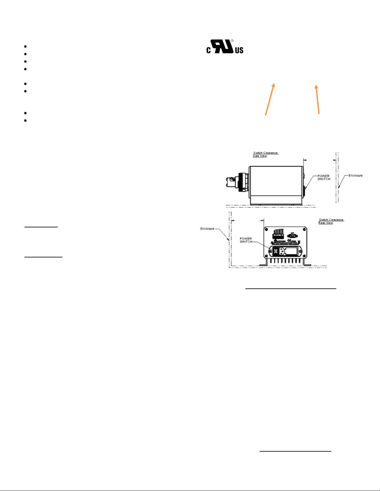
IMPORTANT When mounting PDS-100 in an enclosure it is
important to maintain a minimum clearance to provide adequate
space to reach the power switch. See figure 2.
Figure 1
PDS-100 Rear View
Figure 2
Minimum Power Switch Clearance
Figure 3
Required Mounting Pattern
Specifications
Supply Voltage: 100-240VAC +/- 10%, 50/60 Hz. Main Supply
Current: 0.6 to 0.25 Amps. Fuses: T250V-1A (time lag), 5x20mm, 2
required.
Physical: Dimensions: 5" H x 6 1/4" W x 12" (max) D; Weight: 7 lbs
Environment: For indoor use only. Humidity: 80% max for
temperatures up to 31°C, decreasing linearly to 50% relative humidity
at 40°C. Pollution degree, 2. Operating temperatures range from 5ºC
to 40ºC (41ºF to 104ºF).
4.0”
MINIMUM SIDE
CLEARANCE
REQUIRED
4.0”
MINIMUM REAR
CLEARANCE
REQUIRED
Switch Clearance
Rear View
IN-PDS100-13A
11/1/13 HW
Page 2 of 18
Page 3
PDS-100
Duo Drive
Precision Dispenser
Software
Version
Pumps
home
Duo Mode
USE ARROWS TO SELECT
A = Dispense
B = Dispense
PRESS ‘ENTER’ TO ADJUST
Pump B
Pump A
IN-PDS100-13A
11/1/13 HW
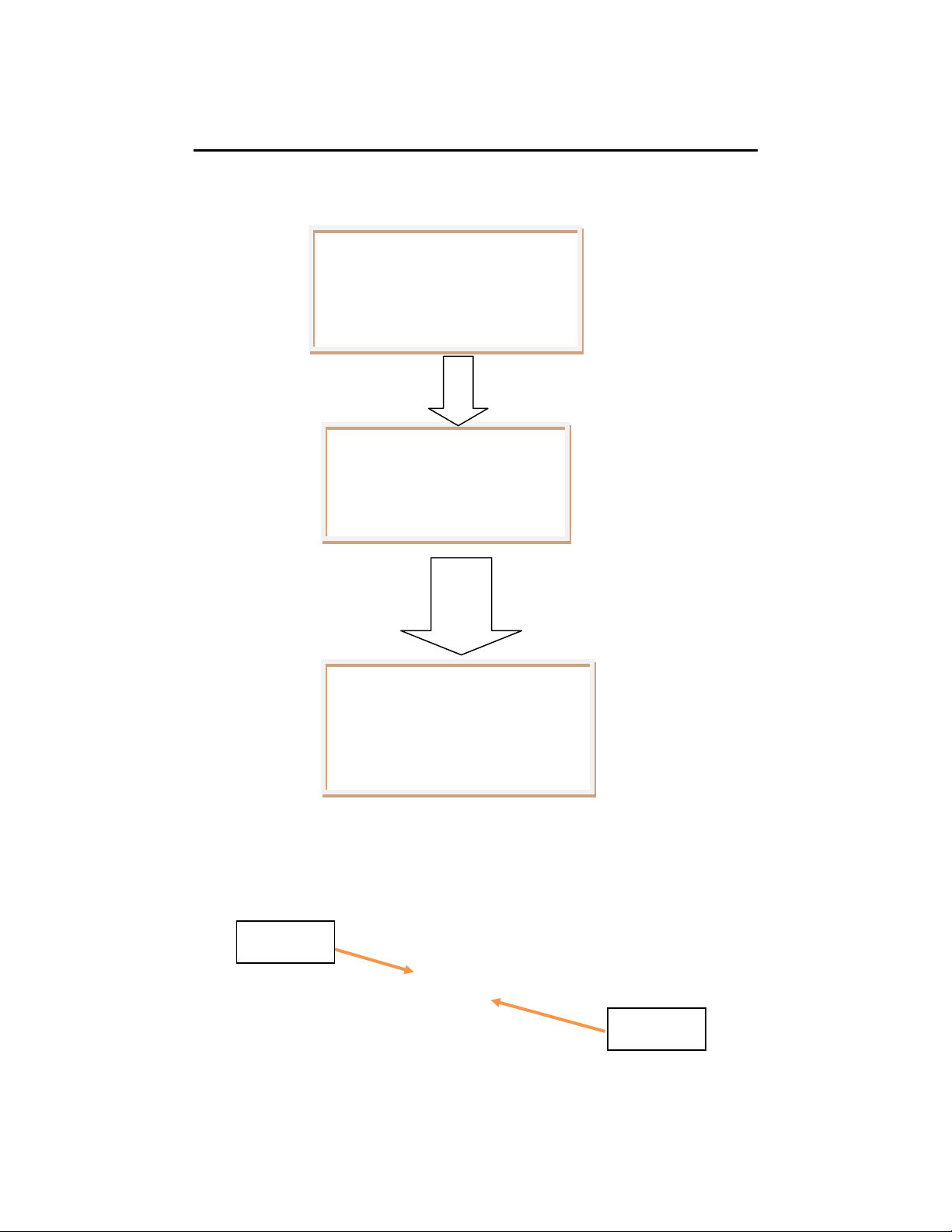
Power Up Screens (two individually controlled pumps)
This is what will be seen on power up when the unit is configured for individually controlled
pumps (factory default). For Single pump configured system use “Pump A” screens only.
Figure 4
Pump A & Pump B Location
Page 3 of 18
Page 4
Setup A = Prime
‘ENTER’ FOR NEXT MENU
Speed = 200 rpm
Run = Start&Stop
USE ARROWS TO SELECT
Setup A = Purge
‘ENTER’ FOR NEXT MENU
Speed = 200 rpm
Run = Start&Stop
USE ARROWS TO SELECT
Setup A = Mode
‘ENTER’ FOR NEXT MENU
Mode = Dispense
Direction = CW
USE ARROWS TO SELECT
Setup A = Inputs
‘ENTER’ FOR NEXT MENU
Control = Keypad
Start = Keypad
USE ARROWS TO SELECT
Setup = RS485
‘ENTER’ FOR NEXT MENU
Interface = 2 Wire
Device Addr. = 5
USE ARROWS TO SELECT
IN-PDS100-13A
11/1/13 HW
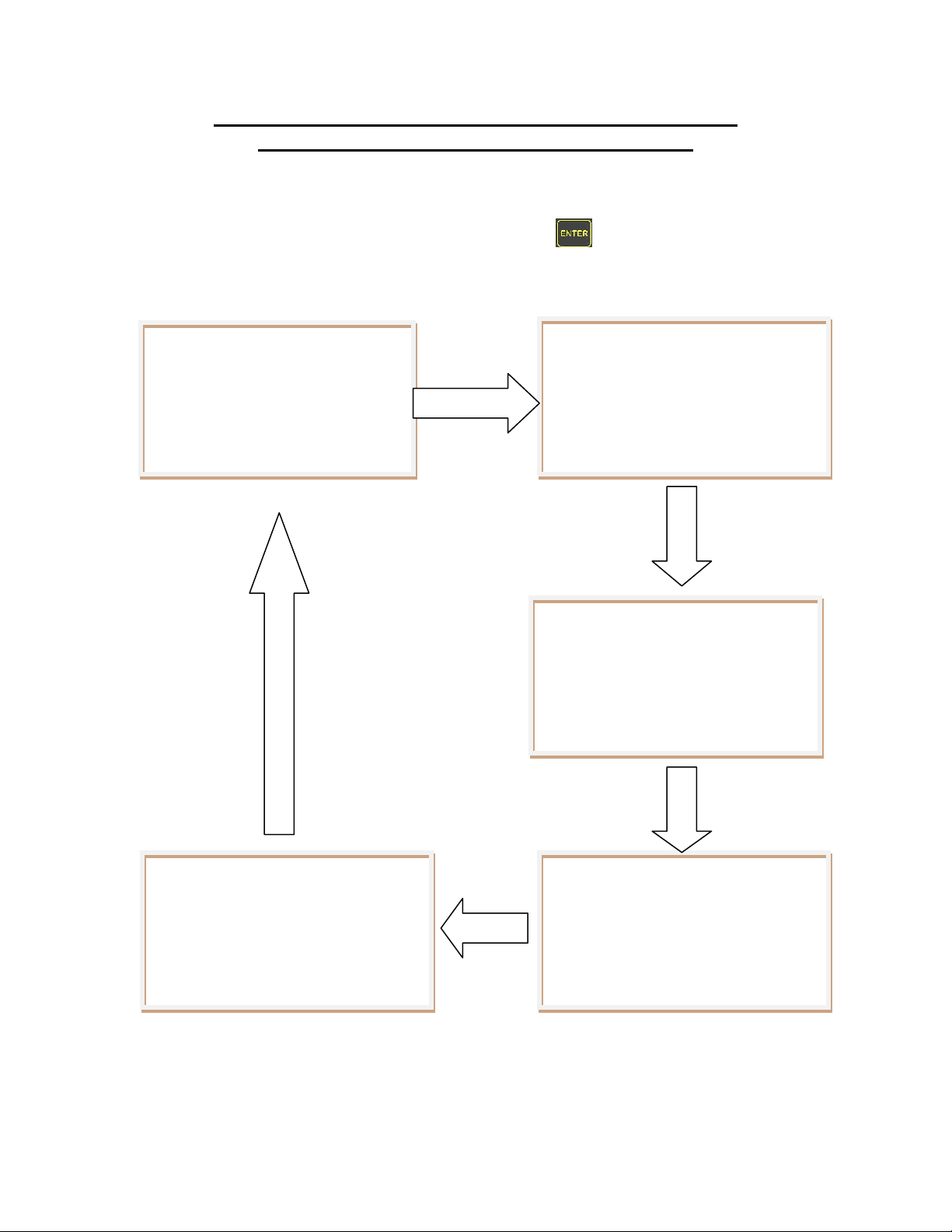
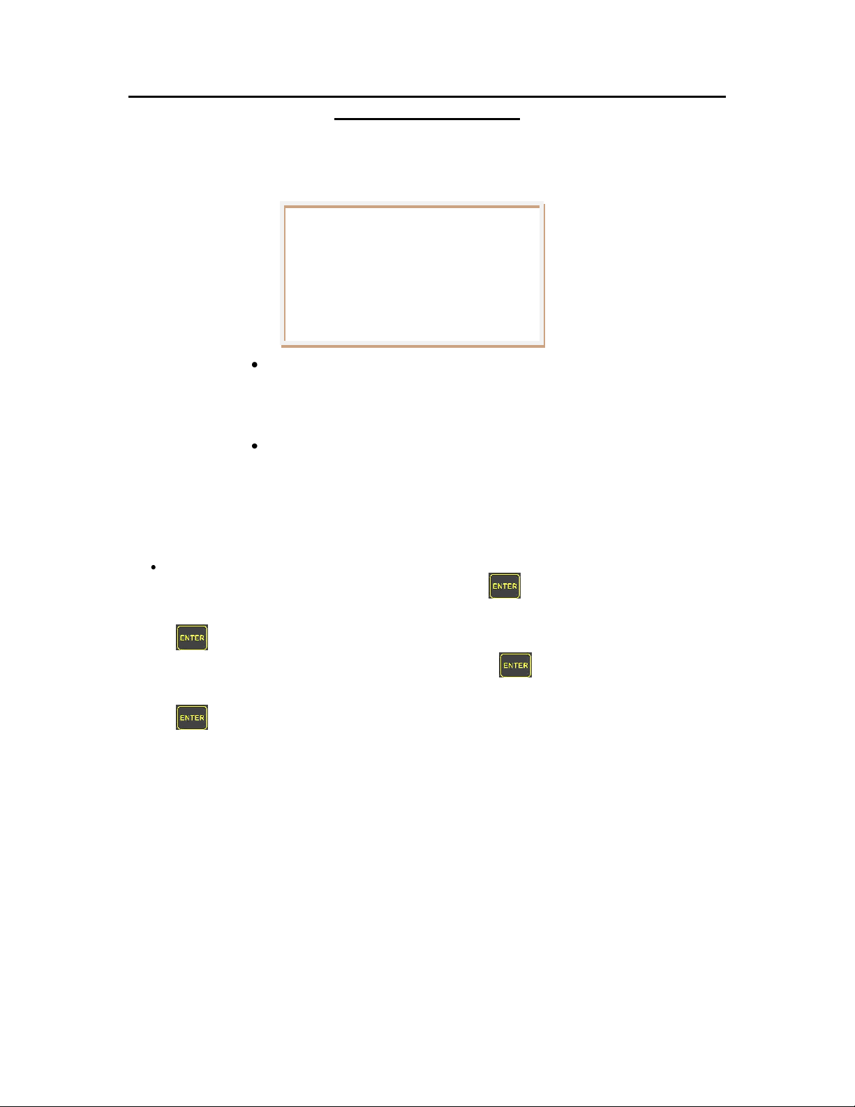
Setup Screens (two individually controlled pumps)
Prime/Purge, Mode & Input Setup Screens
To select “Prime/Purge, Mode & Input Setup” screen wait for the pumps to home then press the
up up/down arrow to select desired pump (A or B: see figure 4) and then press the Setup
button. The following screens are available. Pressing enter will go to each screen.
Pressing the up or down arrow will select additional items.
***Factory default values shown***
Only appears if RS485 is selected
for Control mode and/or Start mode
on previous (Inputs) screen.
Page 4 of 18
Page 5

Setup Screens (two individually controlled pumps) cont’d:
Setup A = Prime
‘ENTER’ FOR NEXT MENU
Speed = 200 rpm
Run = Start&Stop
USE ARROWS TO SELECT
Setup A = Purge
‘ENTER’ FOR NEXT MENU
Speed = 200 rpm
Run = Start&Stop
USE ARROWS TO SELECT
IN-PDS100-13A
11/1/13 HW
Prime/Purge adjust and activation
Prime and Purge have the following available settings.
***Factory default values shown***
Speed (7 – 749 RPM for the STH & RH and 7 – 599 RPM for the STQ &
STQP)
Run
1. Run = “Start&Stop”. Start prime/purge via keypad “Run” and
stop prime/purge via “Stop”
2. Run = “Ext. Switch”. Start prime/purge via external switch.
Pump will continue to prime/purge until switch is released.
Switch A activates pump A and Switch B activates pump B.
3. Run – “Start&Hold”. Start prime/purge via keypad “Run”.
Prime/purge will continue until the Run button is released.
To adjust either the speed or run method simply press the up or down arrow
keys to go to the desired item and then press the enter key to select. To set the
speed press the up/down arrow keys until the desired speed is shown. Press
enter key to save. To set the desired run method press the up/down
arrow keys until the desired run method is shown. Press enter key to save. To
start the Prime/Purge process use the device chosen (Keypad run button or external
switch). To exit setup press the setup key and the motor(s) will automatically home
or press the enter key to go to the next setup screen.
Page 5 of 18
Page 6
Setup Screens (two individually controlled pumps) cont’d: Mode
Setup A = Mode
‘ENTER’ FOR NEXT MENU
Mode = Dispense
Direction = CW
USE ARROWS TO SELECT
IN-PDS100-13A
11/1/13 HW
and direction adjust
Mode has the following available settings for direction.
***Factory default values shown***
Mode
o Continuous (pump will run until a Stop command is given).
o Dispense (pump will run until a Stop command is given or the
programmed dispenses is reached)
Direction
o CW
o CCW
NOTE: When operating in dual pump mode, the direction will
change both pumps. Independent direction control is not available.
To adjust either the mode or direction simply press the up or down arrow keys
to go to the desired item and then press the enter key to select. To set the mode
press the up/down arrow keys until the desired mode is shown. Press the enter
key to save. To set the desired direction press the up/down arrow keys
until the desired direction is shown. Press the enter key to save. To exit setup
press the setup key and the motor(s) will automatically home or press the enter
key to go to the next setup screen.
Page 6 of 18
Page 7

Setup A = Inputs
‘ENTER’ FOR NEXT MENU
Control = Keypad
Start = Keypad
USE ARROWS TO SELECT
IN-PDS100-13A
11/1/13 HW
Setup Screens (two individually controlled pumps) cont’d:
Control and start method
Input has the following available settings for Input control type and start method.
***Factory default values shown***
Control (Speed). Speed can be adjusted prior to run command from
one of the following 5 options listed below:
o RS485
o 4-20 mA
o 0-10 V. (VDC)
o 0-5 V. (VDC)
o Keypad. The pump speed can be adjusted via the keypad
up/down arrow keys.
Start. The pumps can be activated (started) from one of the following 5
options listed below:
o RS485
o Analog (pump(s) will start when a voltage is applied to the
pump(s) Analog Input(s) based on Table 2, pg. 12.
o Power Up: The pumps will start to dispense/meter after power is
applied. Note: The pumps initially “home” prior to starting the
dispense/metering process. In dispense mode the pumps will
stop rotating once the desired dispense count is reached. The
keypad stop button can also activate a stop command.
o Switch. Momentary closure will activate a pump in dispense
mode. In continuous mode the pumps will only rotate while the
switch is closed. Upon switch removal the pumps will complete
rotating until “home” is reached.
To adjust either the control method or start method simply press the up or down
To set the control method press the up/down arrow keys until the desired
control method is shown. Press the enter key to save. To set the start method
press the up/down arrow keys until the desired start method is shown. Press
the enter key to save. To exit setup press the setup key and the motor(s) will
automatically home or press the enter key to go to next setup screen.
o Keypad. The pump will start when the keypad start key is
pressed and stop when the stop key is pressed.
arrow keys to go to the desired item and then press the enter key.
Page 7 of 18
Page 8

Setup = RS485
‘ENTER’ FOR NEXT MENU
Interface = 2 Wire
Device Addr. = 5
USE ARROWS TO SELECT
IN-PDS100-13A
11/1/13 HW
Setup Screens (two individually controlled pumps) cont’d
RS485 setup
RS485 has the following available settings for Interface & Device Address
***Factory default values shown***
Interface. 2 wire or 4 wire
Device Address. Up to 31 (address #1 to #31) units can be
independently addressed.
To adjust either the interface type or device address simply press the up or down
arrow keys to go to the desired item and then press the enter key. To set the
interface type press the up/down arrow keys until the desired control method is
shown. Press the enter key to save. To set the Device Address press the up/down
arrow keys until the desired address is shown. Press the enter key to
save. The address selected applies to both pumps in a dual pump system. To exit setup
press the setup key and the motor(s) will automatically home or press the enter
key to go to the next setup screen.
Page 8 of 18
Page 9

Duo Mode
USE ARROWS TO SELECT
A = Dispense
B = Dispense
PRESS ‘ENTER’ TO ADJUST
A=Dispense
USE ENTER WHEN FINISHED
Speed = 200 rpm
Strokes = 10
USE ARROWS TO ADJUST
A=Dispense
USE ENTER WHEN FINISHED
Speed = 200 rpm
Strokes = 10
USE ARROWS TO ADJUST
Duo Mode
USE ARROWS TO SELECT
A = Dispense
B = Dispense
PRESS ‘ENTER’ TO ADJUST
IN-PDS100-13A
11/1/13 HW
Main Screen (both pumps in dispense mode): Speed/Strokes
adjust via keypad
Press the up/down arrow keys then
the enter key to adjust the desired pump
Speed can be adjusted based on the control type selected from the Input Setup section in the
manual. By default the PDS-100 is configured for Keypad Control and Keypad Start.
To adjust the speed press the up arrow key and then press the enter key. Press the
up/down arrow keys to adjust and then press the enter key when finished to save.
To adjust the number of strokes press the down arrow and then press the enter key.
Press the up/down arrow keys to adjust and then press the enter key when
finished to save. Press the enter key one final time to go back to the main screen.
Page 9 of 18
Page 10

Main Screen (Pump A in continuous mode &
Duo Mode
USE ARROWS TO SELECT
A = Continuous
B = Dispense
PRESS ‘ENTER’ TO ADJUST
A = Continuous
USE ENTER WHEN FINISHED
Speed = 200 rpm
Control = Keypad
USE ARROWS TO ADJUST
Duo Mode
USE ARROWS TO SELECT
A = Continuous
B = Dispense
PRESS ‘ENTER’ TO ADJUST
A = Continuous
WAITING FOR START KEY
Analog = 200 rpm
Control = 0-5 v.
IN-PDS100-13A
11/1/13 HW
Pump B in Dispense mode): Speed adjust from external source
Press the up/down arrow keys
then press the enter key to adjust the
desired pump
To adjust the speed press the up/down arrow keys until the desired speed is set. Notice
how the speed immediately begins to adjust. To save press the enter key. The unit returns
to main screen
If the unit has been configured for other forms of speed control other then Keypad then the speed
can only be set by that type of control. For example, if the speed control is set for 0-5 V then the
following screen will be seen.
Page 10 of 18
Page 11

Analog Input Connector and Specifications
Signal
Description
Shield
Cable shield (terminate one end only)
Common
Ground
Switch A
Activates Prime, Purge and Start for Pump A
when connected to Common and configured as
such (TTL open collector or dry contact)
Switch B
Activates Prime, Purge and Start for Pump B
when connected to Common and configured as
such (TTL open collector or dry contact)
Analog A
Controls the speed of Pump A via an external
voltage or current when configured as such
Analog B
Controls the speed of Pump B via an external
voltage or current when configured as such
Analog/Switch Input
Terminal Strip
IN-PDS100-13A
11/1/13 HW
The PDS-100 incorporates a simple screwless (spring loaded) terminal strip (see figure 6) for
easy wire (22 to 14 AWG) connection to an external control source such as a PLC. It is
recommended that a DIN wire ferrule be used (See figure 5).
Figure 5
Wire Ferrule
Figure 6
Analog Pump Control Connector (Rear Panel)
Table 1
Analog/Switch Input Connector
Page 11 of 18
Page 12

Analog Input Connector and Specifications (cont’d)
RPM
4 - 20 (mA)
Input
resistance
490 ohms
(note 3,1,4)
0 - 5 (VDC)
(note 2,1)
0.5 - 10
(VDC)
(note 2,1)
Analog Input
Min
Max
Min
Max
Min
Max
Min
Max
4 - 20 mA
0 - 5 VDC
0 - 10 VDC
Standard H Pump
6
750
1.6 20 0.2 5 0.2 10
See Waveforms 1 to 9
Standard Q Pump
600
Standard STQP
Pump
700
IN-PDS100-13A
11/1/13 HW
Figure 7
Input Resistance Schematic (Analog input: 0 – 5 VDC or 0 – 10 VDC)
Table 2
Input Voltage/Current versus RPM
Note 1: Maximum current is reduced provided control method is set according to actual
input method (ie 0 – 5 VDC or 0 – 10 VDC). If desired control method is set for
“4–20mA” but a 0 – 5 VDC or 0 – 10 VDC is applied the maximum current will be
at its greatest.
Note 2: Absolute maximum input voltage is 10.8 VDC
Note 3: Absolute maximum current is 22 mA
When start/stop is controlled via the analog input the pump(s) will stop when the analog input
goes below the minimum voltage/current. The pumps will run when the minimum voltage/current
is reached and will run at the minimum speed.
Page 12 of 18
Page 13

RS485 Connector Pin, command set and specifications
Pin On DB9
Male
Connector
Signal
EIA/TIA-485 name
8
RXD0
A’
4
RXD1
B’
5
TXD1 B 9
TXD0 A 1
Common
C/C’
Pin On DB9
Male
Connector
Signal
EIA/TIA-485 name
5
D1
B | B’
9
D0
A | A'
1
Common
C | C’
RS485 DB9 Male
Connector
(2 wire)
(4 wire)
Important: For all industrial environments, it is recommended that an isolation /surge protection adapter
be used to protect the PDS-100 from external high voltages (for example: Aaxeon UTS-401B-SI.)
IN-PDS100-13A
11/1/13 HW
Figure 8
RS485 Control (Rear Panel)
Figure 9
RS485 Control (Rear Panel)
Table 3
RS485 DB9 pin out assignments
PDS-100 follows the guidelines per MODBUS over Serial Line protocol
Port Settings
Baud Rate 19,200
Stop Bits 1
Data Bits 8
Parity Even
Page 13 of 18
Page 14

RS485 Connector Pin, command set and specifications (cont’d)
DRIVE
CODE
Single (RH)
16384
Single (STH)
16385
Single (STQ)
16386
Single (STQP)
16387
Individual (RH)
49152
Individual (STH)
49153
Individual (STQ)
49154
Individual (STQP)
49155
In phase (RH)
49664
In phase (STH)
49665
In phase (STQ)
49666
In phase (STQP)
49667
Out of phase (RH)
50688
Out of phase (STH)
50689
Out of phase (STQ)
50690
Out of phase (STQP)
50691
Smooth (RH)
52736
Smooth (STH)
52737
Smooth (STQ)
52738
Smooth (STQP)
52739
Configuration Table
IN-PDS100-13A
11/1/13 HW
Note: PDS-100 accommodates up to 31 addressable units.
Command Mapping
Single bit read and write. Set bit to initiate action, PDS-100 will clear bit upon execution
Coil 0 = "start" > Pump A – (all configurations except individual – individual pump A only)
Coil 1 = "stop" > Pump A – (all configurations except individual – individual pump A only)
Coil 2 = “start-2" > Pump B – (individual configuration only)
Coil 3 = "stop-2" > Pump B – (individual configuration only)
Single bit status, read only
Input 0 = "busy" > Pump A – (all configurations except individual – individual pump A only)
Input 1 = "error” > Pump A – (all configurations except individual – individual pump A only)
Input 2 = "busy-2" > Pump B – (individual configuration only)
Input 3 = "error-2" > Pump B – (individual configuration only)
16 bit word read and write. Not allowed to change when pump is busy
Holding Register 0 = "rpm" > Pump A
Holding Register 1 = "stroke count" > Pump A
Holding Register 2 = "rpm-2" > Pump B
Holding Register 3 = "stroke count-2" > Pump B
16 bit word information read only
Input Register 0 = "configuration" *see configuration table
Input Register 1 = "operating mode" 0=continuous, 1=dispense
Input Register 2 = "operating mode-2" 0=continuous, 1=dispense
Input Register 3 = "error code" 0= no error, 1= error
Input Register 4 = "error code-2" 0= no error, 1= error
Input Register 5 = "minimum-speed"
Input Register 6 = "maximum-speed"
Page 14 of 18
Page 15

PDS-100
Configuration
Setup
Software
Version
Setup = Mode
‘ENTER’ FOR NEXT MENU
Pump = RH
Drive = Out Phase
USE ARROWS TO SELECT
IN-PDS100-13A
11/1/13 HW
Configuration Modes Screens
(Appears when Up Arrow and setup Keys are held down while powering up unit)
The unit comes pre-configured as a Dual Individual system when purchased as a dual pump
system. To configure the dual pump system for “In Phase” operation or “Out Phase” operation
follow the procedure mentioned above to modify. If the unit supplied is a single pump system
there is no need to change the configuration.
Possible drive configurations types supported (configured by factory):
1. Single: Single pump.
* 2. Individual: Two pumps that can be controlled independently
3. In Phase: Two pumps that are in phase with each other.
4. Out of Phase: Two pumps that run 180 degrees out of phase for each other.
5. Smooth: Requires factory calibrated pump drive assembly. Not covered in this
manual.
* Default Setting
The following screens will be seen when entering the configuration mode. The configuration
mode can only be entered if the up arrow key and setup keys are held down while
powering on the unit. After configuration selection is made, power down and then restart the unit
for changes to take effect.
Page 15 of 18
Page 16

Table 4
Pump Operating Parameters
Waveform Graphs 1 - 9
Waveform #1
Waveform #2
IN-PDS100-13A
11/1/13 HW
Page 16 of 18
Page 17

Waveform #3
Waveform #4
Waveform #5
Waveform #6
IN-PDS100-13A
11/1/13 HW
Page 17 of 18
Page 18

Waveform #7
Waveform #8
Waveform #9
IN-PDS100-13A
11/1/13 HW
Page 18 of 18
 Loading...