

Page 1
Before using any Fluid Metering, Inc. product read the following safety instructions
as well as specific product specifications and operating instructions.
Warning!
Fire, electrical shock or explosion may occur if used near combustibles
explosive atmosphere, corrosive air, wet environment or submerged in fluid.
!
Caution! Fire, electrical shock, injury and damage may
occur if not used in accordance with Fluid Metering, Inc.
specifications and operation instructions.
Do not put wet fingers into power outlet of unit.
Do not operate with wet hands.
Do not operate drive assemblies that require a hard mount
(to be bolted down) unless they are mounted per Fluid Metering, Inc.
specifications, if not injury may occur and/or damage to unit.
Do not touch any rotating pump or motor components: injury may
occur.
Do not run pump dry, unless designed for that service.
Running dry is harmful to the pump, and will cause excessive heating
due to internal friction.
Check pump rotation and inlet/outlet pump port orientation before
connecting power to pump. If not injury may occur.
When pulling out cords from outlets do not pull cord, grasp plug to
prevent plug damage or electrical shock.
Fluid Metering, Inc. Drive Motors become HOT and can cause
a burn
. DO NOT TOUCH!
Turn off the electrical power before checking pump for any problems.
Connect motor, speed controllers, or any other electrical devices
based on Fluid Metering Inc. specifications. Any unauthorized work
performed on the product by the purchaser or by third parties can impair product functionality and thereby relieves Fluid Metering, Inc.
of all warranty claims or liability for any misuse that will cause
damage to product and/or injury to the individual.
Power cables and leads should not be bent, pulled or inserted by excessive force. Otherwise there is a threat of electrical shock or fire.
Replace any inline fuses only with fuse rating as specified by Fluid Metering, Inc.
When pump/drive is under operation, never point discharge tubing into
face or touch any rotating components of pump.
In a power down thermal overload cut-in condition, unplug or turn off
power to pump. Always allow a cool down period before restarting:
otherwise, injury or damage may occur.
For 30 seconds after power is removed from pump/drive: do not
touch any output terminals. Electrical shock may occur because of
residual voltage.
!
SAFETY INSTRUCTIONS
General Instructions
Congratulations! You are about to install the newest technology from FMI, designed specifically
for industrial dispense applications, where long-term trouble-free performance is expected. If
you have any questions during any stage of your installation please don't hesitate to give us a
call. Our technical staff is ready with answers. Call us at 1-800-223-3388. LET'S GET
STARTED!
Your controller is initially set to provide one dispense per signal at 320 strokes per minute.* Dispense signal, other speed settings, and dispense values are easily set by following the detailed
instructions on the following pages. * Best speed for most dispense applications.
Connect cable from CONNECTOR P1 on the housing to your PLC or controller and power supply as per the following pin connections. NOTE: Not all the available functions may be suitable
for your application; therefore some wires may not need to be connected.
1
IN-IDS-08
IDS INDUSTRIAL DISPENSER
INSTRUCTIONS
1
!
Page 2
IN-IDS-08IN-IDS-08
2
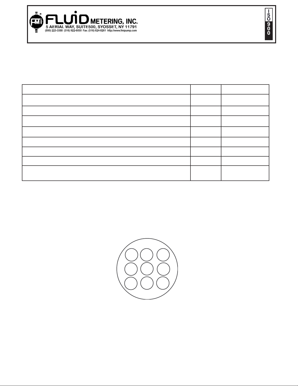
The following connections are made through the 6' cable provided. It has a nine-pin Amp Series 1, Circular Connector, shell size 13, arrangement 13-9, standard sex (Plug/Socket). This connector is P1 on
Figure 1
.
1. Power positive (+24-30VDC Max) Fused 2.5 Amp Time Lag Pin #1
Red
2. Power Ground Pin #2 Black
3. Flag Verify, (+Side Sinking Open Collector) 12-30 V Max @ 20mA max Pin #3 Blue
4. Safety Ground Pin #4 Green/Yellow
5. Flag Verify, Return, Emitter
Pin #5
Orange
6. Start (+Side Sinking Opto-Isolator LED Input) 12-30 V Max @ 20mA Pin #6
Yellow
7.Start Return - Signal Common Pin #7 White
8. Analog Volts Input, 0.1-5.0 V Max (Optional) Pin #8
Brown
9. Dispense/Run (+Side Sinking Opto-Isolator Input) 12-30 V Max @ 20mA Pin #9 Violet
FMI provides a 6' (2 meters) shielded 9-pin hook up cable, Part No. 200204.
P1 INPUT CONNETOR VIEWED
FROM OUT SIDE BOX
FIGURE 1
IDS INDUSTRIAL DISPENSER
INSTRUCTIONS
1
1
4
7
2
5
8
3
6
9
Page 3
IDS INDUSTRIAL DISPENSER
INSTRUCTIONS
3
1.0 Description
The IDS Industrial Dispenser has a stepper motor and a self-contained step motor controller specifically
designed for use with Fluid Metering valveless pumps. It contains its own step output drivers and can be
set to several run modes utilizing either internal or external controls. This system is designed for maximum performance in all industrial situations. If you have any questions at all, please don't hesitate to call
our technical hot line at 1-800-223-3388.
1.1 Features
• Pre-set Run Modes.
• Multiple Control Methods: PLC *, Relay, 0-5 VDC, or manually by internal switches.
• Dispense Run, Purge, etc.
• Variable speeds.
• Verification of dispense cycle and rotation.
• Opto-isolated inputs.
• Auto-Current reduction, when not in a running mode.
• Internally fused at 2.5 A via a plug-in fuse socket.
• Automatic over temperature shutdown of drive current output if driver devices reach 70 º C internal
temper atures. Note: This does not prevent motor overheating!
• Rugged 304 Stainless Steel, NEMA type 12, IP 65 enclosure.
• Forward/Reverse Function Default SW 12 Open is clockwise direction
*Typical compatible PLC's are: Texas instruments Ti 305, SIMATIC, GE Fanuc OCS stations, Crouzet
Type RPX and DIAL 5, DIAL 10 systems, IDEC's series of Micro 3 or Micro 3 C and PLC Direct DL105
through DL 405. PLCs require opto-isolated or relay outputs for start, run or dispense functions and an
opto-isolated current loop input.
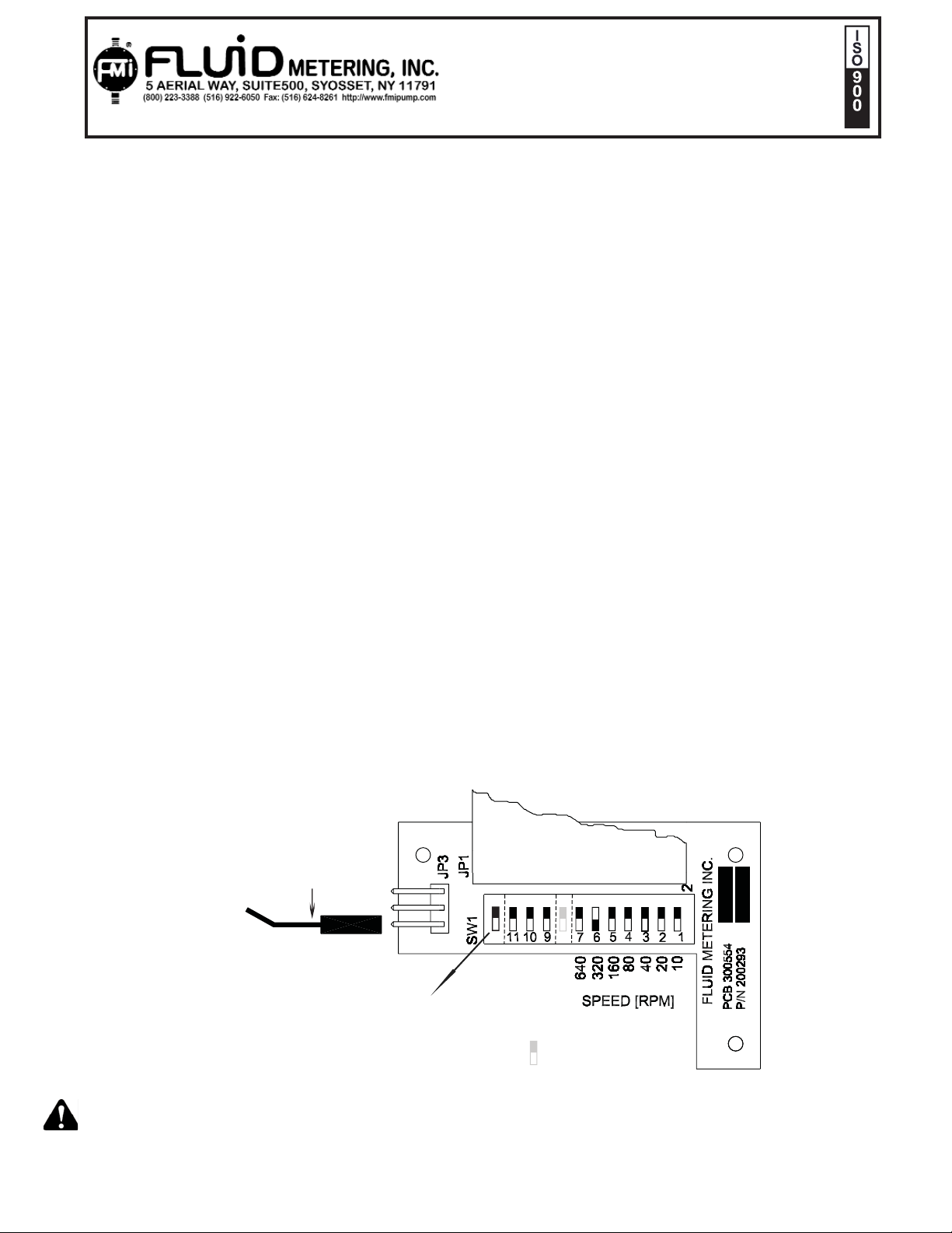
2.0 Run Modes
The step motor controller board housed in the IDS can drive pumps in any of the following modes by
changing switches on the Switchboard 200293 as shown below.
8
OFFOFF
ENCLOSURE FASTENERS MUST BE TORQUED TO 6 INCH POUNDS ± 10% TO ASSURE PROPER SEALING.
1
'RED' Jumper
Dispense control
11
10
9
switchboard #200293
OPEN
*
12
124
Dispense
FWD/REV
Switches
*#8 Always off
Page 4
IN-IDS-08
4
OPEN
8
0
60
0
OFF
S
U
G
C.
4
7 6 5 4
3
Fig 2A
2.1 Dispense Mode:
The IDS comes factory set for one dispense revolution** per signal at 320 rpm* Dispense start actuation
is handled by pins 6 (YELLOW) and return pin 7 (WHITE) of the external connector, P1. The minimum
signal input time that this function can respond to is .030 milliseconds (0.020 sec) to a maximum of 100
milliseconds, or less than the time it takes to make one revolution.
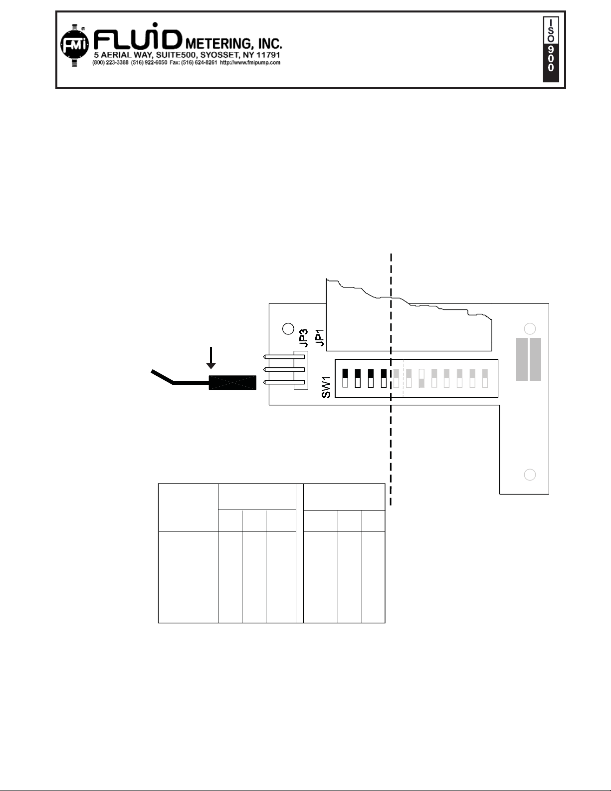
You can, have up to seven shots per signal if desired. The number of shots per Start signal is set by
switches 9, 10, 11 and Red Jumper on Switchboard # 200293. See Matrix below (Figure 2A) **( FMI has
determined that 320 RPM is best speed for a single revolution dispense, this may vary depending on the
hydraulics of your system.)
IDS INDUSTRIAL DISPENSER
INSTRUCTIONS
1
'RED' Jumper
Dispense control
11
10
9
Dispense Matrix
Red Jumper and Switch Settings / Dispense
Dispense /
start
1
2
3
4
5
6
7
Red Jumper
Location
9 10 11
1
0
0
1
1
0
0
0
1
0
0
1
1
0
0
0
0
1
0
0
0
Dispense
switch
9 10 11
0
0
0
0
0
0
0
switchboard
#200293
OFF
12
11 10 9
124
Dispense
Switches
0
0
0
0
1
0
0
0
0
1
0
1
1
1
2
4
0
1
4
PEED[RPM]
1
0 = OFF
1 = ON
IN
ID METERIN
B 30055
/N 200293
FL
Page 5
IN-IDS-08
5
VOLTS OPTO-OUTPUT
OHMS
TRANSISTOR OUTPUT
OHMS
RELAY OUTPUT,
OHMS
6 220 220 270
9 390 390 470
12 620 620 680
15 820 820 820
18 1000 1000 1000
24 1300 1300 1500
28 1600 1600 1800
30 2000 2000 2000
NOTE: These are the closest values of current limiting 5%, ¼ watt resistors for the applied voltages. Voltage control sources must have series resistors as shown in Table above, to limit control signal currents to
the input opto-isolators, Pins 3, 6, 9, on P1.
2.2 RUN / PURGE MODE
A current of 6 to 20mA must be supplied continuously throughout the signal current input at P1, Pin 9
(VIOLET) to keep the dispenser in a continuous run mode. THE ABSENCE
OF THIS SIGNAL WILL
HOLD THE PUMP IN A DISPENSE MODE ONLY. Run / Purge Actuation is handled by Pin 9 (VIOLET)
(+ side sinking) and 7 (WHITE) (return) on the input connector P1 (see Figure 1, Page 1), by providing a
current of 6 to 20mA through a switch closure, PLC, Relay, Mechanical Timer/Counter or transistor output
2.3 Timed/Count Dispense/Continuous Run Mode
To activate this mode for a timed dispense system, the closing of dispense switch 9 is done externally
using a control signal current input at P1 Pin 9 (VIOLET) for one dispense per signal. The pump will
begin running when this connection is closed
, and rotation will cease when the control current is turned
off from Pin 9 of P1. The current must be provided through a resistor (the typical values are shown
on Table 2 below) from a counter or timer that can control a SPST relay or switch closure. External
counters and PLCs can use the VERIFY SIGNAL OUTPUT (P1 Pin 3 (BLUE), verify return common Pin 5
(ORANGE)) to sense and count each revolution pulse. If no PLC is used, a standard industrial counter
such as OMRON H7CR can be set to count up to 9999999 revolutions, and then stop.
Table 2
IDS INDUSTRIAL DISPENSER
INSTRUCTIONS
1
Page 6

IN-IDS-08
6
2.4 External Control 0-5 VDC - Voltage Following Input Mode
In order for the stepper controller board to recognize and accept a 0-5 VDC control input, all speed
switches 1-7 (Switchboard #200293, Figure 2,) must be turned off. The board will not respond to a
voltage input unless all speed switches are off. Once off, a DC voltage (5.0 volts max.) signal may be applied via the input cable (P1) Pin 8 (RED) (+ voltage) and Pin 7 common returns. A variation of that voltage will linearly vary the motor speed. Maximum speed using a 0-5 volt DC input signal is limited to
approximately 2000 rpm. (The smallest increment is about 6 rpm.)
2.5 Continuous (Constant Run) Mode
By turning off the Dispense switches 9, 10, 11 on the Switchboard, and having a current signal at P1 Pin
9 (VIOLET), the motor will run at a continuous pre- set speed. This condition is useful for priming the
system.
Speed (factory set at 320rpm) may be changed according to section 5.0
3.0 Motor Direction
Factory preset to CLOCKWISE looking into the pump head. Suction is on the RIGHT, discharge on the
LEFT, when the pump head is facing you. Counter Clockwise rotation is settable by closing SW12 on
Switchboard # 200293 inside of the box. See section 5.0 * This Function is not Accessible on Connector
P1.
4.0 Power Supply requirements
A single 24 VDC power supply delivering 2.0 amps (minimum) of current is required for driving the
IDS 2000A. Connect positive (+) to P1 Pin 1 (RED) and negative (-) to P1 Pin 2 (BLACK). An addi-
tional power supply may be needed to provide input currents to the control inputs, if they are not internally
sourced from your controller.
IDS INDUSTRIAL DISPENSER
INSTRUCTIONS
1
Page 7

IDS INDUSTRIAL DISPENSER
INSTRUCTIONS
IN-IDS-08
7
O
9
board
s
OFF
OFF
U
G
C.
C
/
4
3
2
200293
9
3
The switches are set up as a binary system. This means that multiple switches will add their values together. For example, to set the motor to run at 500 rpm you must turn on switch 6, 5 and 2 (320+160+20
= 500 rpm). The switches can give a maximum speed of 1000rpm.
The controller will run at a constant pre-set speed via switches 1 through 7, until control current to P1 Pin
9 (VIOLET). is removed. When the current is removed the unit returns to “one cycle per start signal”. At
the first cycle of the dispense mode the pump will “home” itself to the proper starting point. All following
dispense cycles will then home to the proper start position.
Fig 2B
5.0 Speed switches –Switchboard # 200293
The SPEED switches 1 -7 are used for changing the speed settings.
1
'RED' Jumper
Dispense control
JP
witch
P1
W1
Dispense
Switche
10
#
PEN
7 6
640
PEED[RPM]
160
80
20
IN
10
ID METERIN
FL
B 300554
N 200293
P
P
Page 8

IN-IDS-08
8
FIGURE 4 (200145)
IDS INDUSTRIAL DISPENSER
INSTRUCTIONS
1
Page 9

IDS INDUSTRIAL DISPENSER
INSTRUCTIONS
9
Interchangeable pumphead modules permit this industrial dispenser to be
FLOW RANGE
IDS FLOW INFORMATION
Interchangeable pumphead modules permit this industrial dispenser to be
60
100
100
100
5
15
(PSIG) MAX
PRESSURE
60
0 - 320
10000.32Q1 (1/4)
Q2 (3/8)
Q3 (1/2)
operated in any of four flow rate ranges.
RH00 (1/8)
RH1 (1/4)
RH0 (3/16)
operated in any of three flow rate ranges.
900
800
0 - 100
0 - 25
0 - 50
1000
1000
1000
0 - 1000
0 - 650
0.025
0.100
0.050
0.72
1.28
Q0 (1/8)
PISTON
MAXIMUM
1000
RPM
mL/MIN
0 - 80
STROKE
0.08
MAX mL PER
SIZE
If a TIMED/COUNTED dispense is run, the pump will stop at the point of signal turn off. It will NOT
continue to complete the interrupted revolution. The pump will only complete the cycle if a single Start
command is given or as part of the next TIMED /COUNTED cycle.
6.0 Dispense / Flow Rates
To avoid cavitation at maximum speed use maximum internal diameter tubing at the suction side. Cavitation produces noise and inaccuracies of flow.
See 7.0 Calibration
IN-IDS-08
1
Page 10

IDS INDUSTRIAL DISPENSER
INSTRUCTIONS
IN-IDS-08
10
IDS-“Q” Pumphead
direction <right to left
Displacement is adjusted by
changing Angle of pumphead.
Loosen 11/32 hex nut and move
pumphead “left to increase” and
“right to decrease”.
Now recalibrate. Lock hex nut set
and lock Displacement adjust
stop screw.
The Knurled ADJUSTMENT NUT on the
pumphead controls stroke to stroke
Piston displacement. Turning clockwise
to zero stops displacement. Turning the ADJUSTMENT-NUT counterclockwise four and one half turns
from zero (450 on scale) (fig.5) causes maximum
pump reciprocation, e.g., 50 µl per stroke for the H-0
or 100 µ for H-1 unit.
Thus each 1-1/8 turn (112.5 on scale) of the ADJUSTMENT NUT Represents 25% of maximum
(12.5µl for H-0 and 25µl for H-1) and each graduation
on the ring represents an adjustment of 1/450th of
maximum (0.111 µl for H-0, 0.222 µl for H-1).
IDS-“RH” Pumphead
Flow direction> left to right
7.0 Calibration and Displacement
Your IDS comes factory calibrated to maximum displacement of the installed pumphead unless ordered
with specific displacement and calibration.
Recalibration and changes of displacement are relatively easy.
7.1 Calibration for Dispensing
FMI calibrates by weighing 3 or more dispenses on an analytical balance. It then finds the average. The
pumphead displacement is then adjusted as required up or down accordingly. See Fig
1
FIXED CALIBRATION LINE
CALIBRATION RING
Page 11
IDS INDUSTRIAL DISPENSER
INSTRUCTIONS
IN-IDS-08
ALL OIL S AND PART ICLES. BE SURE THE SURFACE
INSTALLATI ON INSTRUCTIONS FOR MOUNTING
8. REPLACE WITH A NEW 300598 PAD IF THE UNIT IS REMOVED.
THERMAL PAD, FMI P/N 300598
1. CLEAN THE MACHINE MOUNTING SURFACE OF
IS FREE OF RAISED GOUGES OR BURRS.
2. CAREFULLY REMOVE T HE BLUE SHEET FROM THE PAD.
3. THE EXPOSED WHIT E SURF ACE IS "TACKY" AND
WILL STICK T O T HE BACK OF THE PUMP ENCLOSURE.
4. ALIGN THE HOLES IN T HE PAD AND MOUNTI NG
6. REMOVE ANY AIR BULGES FROM UNDER THE PAD.
7. BOLT THE DISPENSER IN PL ACE.
SURFACE.
5. PRESS THE PAD INTO PLACE.
FINISH
SURFACE
FINISH
Chemical Metering Pumps
TOLERANCES
UNLESS OTHERW ISE
SPECIFIED
.X = ±.0 15
.XX = ±.010
.XXX = ±.005
MAT'L
DRAWN
BY
CHECKED
APPVD
BY
BY
TITLE
SCALE DWG NO. REV
DATE
DATE
FILEN AM E
APVD
DATEDESCRIP TIONSYM
REVISIONS
DATE
DATE
DWG BY
ORIG.
BY
NOTE : FMI TO B E NOTIF IED IN WRITING P RIOR TO ANY
CHANGES IN MATERIALS, PROCESSES OR CONSTRUCTION.
ANG = ±1°
700023
THERMAL PAD
MOUNTING
LABEL
8/16/02
A
8/16/02
8/16/02
8/16/02
Sht 1 of 1
FMI P/N 700023
1
Page 12

IDS INDUSTRIAL DISPENSER
INSTRUCTIONS
IN-IDS-08
SHT 2 OF 2
G
REV
Syosset,NY 11791
ENCLOSURE
IDS A SERIES,
5 Aerial Way, Suite 500
OUTLINE DRAWING,
Fluid Metering Inc.
R
WITH CSC-TC
OVERALL DIMENSIONS
1
PUMP HEAD MODULE
WITH CSC-WT
OVERALL DIMENSIONS
PUMP HEAD MODULE
TITLE
600059
DWG NO
FMI P/N IDS2000A / IDS2000AGM
CONNECTOR
OUTLINE
IDS2000A / IDS2000AGM
6.0 [152.4]
COVER
4.9 [125]
3.4 [86.4]
1.25" [31.8]
RADIUS =
MIN. BEND
Ø0.30
[7.6](8X)
CABLE
11.8 [300]
TYP
R.50 [12.7]
CABLE
CONNECTOR
OUTLINE
RADIUS =
1.25" [31.8]
MIN. BEND
3.4 [86.4]
6.0 [152.4]
15.8 [401] APPROX.
16.0 [406] APPROX.
12.0 [305]
Ø0.30
COVER
4.9 [125]
[7.6](8X)
TYP
R.50 [12.7]
4.12 [105]
3.5 [88.9]
3.7 [94.0]
TOLERANCES UNLESS OTHERWISE SPECIFIED:
.X = ±.04 [1.0]
NOTE: DIMENSIONS ARE IN INCHES [MILLIMETERS]
DIMENSIONS REPRESENT MAXIMUM VALUES OF PUMP HEAD EXTREMETIES.
.XXX = ±.010 [.25]
.XX = ±.02 [.50]
Page 13

IDS INDUSTRIAL DISPENSER
INSTRUCTIONS
IN-IDS-08
SHT 1 OF 2
2.0 [50.8]
CAUTION
RISK OF DAMAGE TO
9
6
3
7
8
5
4
1
2
ELECTRONICS! TURN
POWER OFF BEFORE
INSTALLING OR REMOVING
POWER CONNECTOR
300598
THERMO PAD
SHELL SIZE 13
ARRANGEMENT 13-9
AMP CIRCULAR CONNECTOR
STANDARD SEX
WITH CSC
OVERALL DIMENSIONS
PUMP HEAD MODULE
1
2.9 [73.7]
4.3 [109.2]
Syosset,NY 11791
5 Aerial Way, Suite 500
Fluid Metering Inc.
R
OUTLINE DRAWING,
TITLE
IDS A SERIES,
G
REV
ENCLOSURE
600059
DWG NO
OUTLINE
CONNECTOR
IDS2000A / IDS2000AGM
6.0 [152.4]
5.4 [137.2]
3.4 [86.4]
1.25" [31.8]
RADIUS =
MIN. BEND
CABLE
11.7 [297.8]
15.7 [398.8] APPROX.
7.50 [190.5]
6.75 [171.5]
0.38 [9.7]
BASE AND THERMO PAD MOUNTING
1.0 [25.4]
2.0 [50.8]
R.50 [12.7]
FMI P/N IDS2000A / IDS2000AGM
TYP
COVER
4.8 [121.9]
3.5 [88.9]
3.7 [94.0]
Ø0.30
[7.6](8X)
TYP
R.50 [12.7]
AMBIENT TEMPERATURE; 41°F - 104°F [ 5°C - 40°C ] IN STILL AIR, MOUNTED
OPERATING CONDITIONS:
GENERAL SPECIFICATIONS:
VERTICALLY, WITH AT LEAST 1 INCH OF CLEAR AIR SPACE ON ALL SIDES. MOUNTING
MAY BE BY 1 INCH WIDE BARS OR CHANNELS. FOR HIGHER TEMPERATURE AMBIENT,
ADDITIONAL HEAT SINKS AND FORCED AIR WILL BE REQUIRED TO KEEP THE
HOUSING OUTSIDE TEMPERATURE TO A MAXIMUM OF 125°F [52°C] ON ANY SURFACE.
RELATIVE HUMIDITY; 30% TO 80% NON-CONDENSING.
ATMOSPHERIC PRESSURE; 10.5 PSI [700 MILLIBARS] TO 15.4 PSI
[1060 MILLIBARS].
AMBIENT TEMPERATURE; 0°F [-18°C] TO 158°F [70°C].
NON-OPERATIONAL CONDITIONS:
RELATIVE HUMIDITY; 30% TO 85% NON-CONDENSING.
ATMOSPHERIC PRESSURE; 7.5 PSI [500 MILLIBARS] TO 15.4 PSI
1060 MILLIBARS].
TOLERANCES UNLESS OTHERWISE SPECIFIED:
.X = ±.04 [1.0]
NOTE: DIMENSIONS ARE IN INCHES [MILLIMETERS]
.XX = ±.02 [.50]
.XXX = ±.010 [.25]
DIMENSIONS REPRESENT MAXIMUM VALUES OF PUMP HEAD EXTREMETIES.
Page 14

IDS INDUSTRIAL DISPENSER
INSTRUCTIONS
IN-IDS-08
FINISH
SURFACE
FINISH
Chemical Metering Pumps
TOLERANCES
UNLESS OT HER WISE
SPECIFIED
.X = ±.015
.XX = ±.010
.XXX = ±.005
MAT'L
DRAWN
BY
CHECKED
APPVD
BY
BY
TITLE
SCALE DWG N O. REV
DATE
DATE
FILENAME
APVD
DATEDESCRIPTIONSYM
REVISI ONS
DATE
DATE
DWG BY
ORIG.
BY
NOTE : FMI TO BE NOT IFIED IN WRITIN G PRIOR TO ANY
CHANG ES IN MATERIALS, PROC ESSES OR CON STRUCTION.
ANG = ±1°
700021
EXAMPLE
IDS 2000A
START SIGNALS
2/5/04
D
6/6/02
2/19/04
2/19/04
Sht 1 of 1
FMI P/N IDS2000A SERIES
1
 Loading...