


ICST-01
INTELLIGENT
STEP MOTOR DRIVE SYSTEM
INSTALLATION --- OPERATION
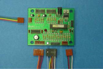
DEVELOPMENT KIT P/N ICST-01
SHOWN ABOVE
This kit is intended for help in setting up your required protocol for your FMI pump / dispenser functions.
1
|
|
Contents |
1. |
SYSTEM SAFETY........................................................................... |
3 |
2. |
SYSTEM DESCRIPTION ................................................................ |
3 |
2.1FUNCTIONS
2.2FEATURES
3. |
SYSTEM INSTALLATION.............................................................. |
4 |
4. |
WIRING SPECIFICATIONS ........................................................... |
5 |
|
4.1 P/N ICST-01 Page 5 |
|
|
4.2 P/N ICST-01 OEM Page 6 |
|
5. |
PROGRAMS AND PROGRAMING ................................................. |
7 |
5.1Program Installation
5.2Program Operation
6. |
SPECIFICATIONS ........................................................................ |
13 |
7. |
TROUBLE SHOOTING................................................................. |
14 |
8. |
TECHNICAL ASSISTANCE.......................................................... |
14 |
BOARD ALONE P/N ICST-01 OEM
SHOWN ABOVE
IN-ICST-01-07 |
2 |
1. System Safety
 CAUTION : To prevent power surge and damage to the board, apply and remove power by the AC source of the power supply. DO NOT PLUG AND UNPLUG AT THE BOARD.
 CAUTION : To insure proper operation of the board be sure all wiring and connections are correct and secure.
 CAUTION : Keep fluids away from the electronics.
 CAUTION : To prevent heat buildup in the motor, current to the motor should be reduced to holding current or turned off between cycles.
2. System Description
The “ICST” is a programmable step motor control intended for use with FMI step motor equipped pumps and dispensers. Using a computer programming adapter and exclusive ICSTPLE (program loader and editor) CD for Windows®, the operator can program the pump / dispenser protocol that fits his application.
2.1 Functions
Fluid Metering Inc. can supply custom programs for the driver to fit most expected conditions. Listed are a few of the functions of the driver boards programming.
Run: Clockwise or counter clockwise at fixed rate or through a profile table. The motor can be accelerated and decelerated through a variable number of steps.
Stop: Stop can be programmed to actuate on either the leading or the trailing edge of the pumps rotational flag. The stop can be also set to go any number of steps past the trip point. For example if the program is set to stop on the trailing edge of the flag, going clockwise this would stop the pump ½ way into the discharge stroke, the program can be instructed to go 100 steps past the flag sense and stop at the bottom of the discharge stroke; without interrupting the rotation. FMI standard (best) stop point is ½ way into the inlet stroke
Flow control: Program flow control includes the following; call, if, else, loop, goto, set, clear, waitfor, repeat, run, halt, stop.
2.2 Features
Designed for maximum performance when mated to FMI 23 and 17 frame 1.8º step motors. Most FMI step motor pumps come standard with a sensor and rotational flag that is aligned to the pump piston. The rotational flag sensor outputs motor and or piston position to the driver.
All external connections to the driver board are via standard Waldom/Molex straight headers, except the power input witch is a standard modular DC center positive receptacle. Development kit has connections via barrier terminal blocks, except power input.
MOTOR OUTPUT POWER: Has three states, full power (1 Amp/Phase), low power (300 ma/Phase), or off. Power settings can be programmed to any state at any time. Ratings are ± 10%.
IN-ICST-01-07 |
3 |
ACCESSORY OUTPUTS: Two dedicated power level outputs rated at supply voltage (24VDC) and 150 milliamps each are available to drive external solenoids or relays.
TTL LEVEL INPUTS: Two dedicated TTL compatible high impedance, single ended, nonisolated, ground referenced, 5V inputs are provided. One is for Fluid Metering Inc. 5-wire optical sensor. The other is high speed input capable recognizing an input pulse with a duration as little as 4 Microseconds.
TTL LEVEL CONTROL: Seven TTL compatible I/O lines are available. These lines are current limited to 5 milliamps each. All I/O lines are fully programmable.
3. System Installation
 CAUTION : To insure proper operation of the board be sure all wiring and connections are correct and secure.
The “ICST” is a bi-polar driver only, set up to work half stepping only. For a standard FMI 1.8º stepping motor, this equals 400 steps per revolution. Speed and rotational calculations need to be made from the 400 steps per revolution.
Stepping motors are made with different numbers of leads, there are 4, 6 and 8 lead motors. The 23 frame motor used on our general product line is an (8) eight lead motor. This motor, for the best performance, works most efficiently when wired bipolar–series. The 17 frame motor is a (6) six lead, and works most efficiently when wired half coil.
23 Frame Stepper.
FMI P/N 110746 (8lead) Connector
Pin 6 RED wire is A Phase Pin 1 YELLOW wire is A bar Phase
Pin 8 GREEN wire is B Phase Pin 3 BLUE wire is B bar Phase Pins 2 & 5 BLACK & WHITE terminated pair.
Pins 4 & 7 ORANGE & BROWN terminated pair.
17 Frame Stepper.
FMI P/N 110745 (6lead) Connector
Pin 3 RED wire is A Phase
Pin 2 BLACK wire is A bar Phase Pin 4 BLUE wire is B Phase
Pin 5 WHITE wire is B bar Phase Pin 1 YELLOW wire is not used Pin 6 ORANGE wire is not used
23 Frame Stepper (STRH). FMI P/N 300615 (8 lead) Used with FMI cable assembly P/N 110711
Pin 1 ORANGE wire is A bar Phase. Pin 2 & 5 WHITE/BLACK & WHITE/ORANGE terminated pair. Pin 3 YELLOW wire is B bar Phase. Pin 4 & 7 WHITE/RED & WHITE/YELLOW terminated pair. Pin 6 BLACK wire is A Phase.
Pin 8 RED wire is B Phase.
See Section 4, P/N ICST-01 or P/N ICST-01 OEM for the correct wiring, phase relationship, of the motor to the driver. Motors shown are standard FMI pump drive motors.
For other motor wiring contact Fluid Metering.
FMI Sensor (STD. Optical Sensor) P/N 110569
This is a 5 lead inverted open collector output sensor. Signal goes high when the light source is blocked. The pull-up and load resistors are built into the driver, so that the sensor can be directly wired to the driver board.
RED wire is + V for the Ired LED.
BLACK wire is the ground for the Ired LED.
WHITE wire is the + V for the output.
GREEN wire is the ground for the output.
BLUE wire is the inverted open collector output to the controller.
IN-ICST-01-07 |
4 |

NOTES ON TTL LOGIC: For interface to PLC or other type of control.
TTL |
(Logic High) |
≥ 2.0 Vdc |
TTL ( logic Low) |
≤ 0.6 Vdc |
|
Vin ( Absolute Maximum) = 5Vdc
Vin ( Absolute Mininum) = 0.0Vdc
Vin ( Logical High) = ≥ 3.5 Vdc.
Vin ( Logical Low) = ≤ 1.0 Vdc.
ACCEPTABLE INPUTS
5 Vdc
DRY CONTACT |
OPEN COLLECTOR |
TTL or CMOS LOGIC |
|
(OPEN DRAIN) |
|
4. Wiring Specifications
4.1 P/N ICST-01
Wiring for terminal strip marked J12:
Number 1 is the B bar phase to the motor.
Number 2 is the B phase to the motor.
Number 3 is the A bar phase to the motor
Number 4 is the A phase to the motor.
Number 5 is the Black wire from the sensor.
Number 6 is the Red wire from the sensor.
Number 7 is the Green wire from the sensor.
Number 8 is the Blue wire from the sensor.
Number 9 is the White wire from the sensor.
Note: See section 3 system installation for motor wiring.
Number 10 is the Brown wire for Relay 1 (- side activated).
Number 11 is the Orange wire for Relay 2 (- side activated).
Number 12 is the 2 Red wires (+24 Vdc) for Relay power.
Wiring for terminal strip marked J11:
Numbers 1 and 2 are Ground, the Lt Blue wire two places.
Number 3 is the Push Button Switch (Activation Switch), the Yellow wire. Number 4 is the Dip Switch 1 (I/O1), the Black wire.
Number 5 is the Dip Switch 2 (I/O2), the Purple wire. Number 6 is the Dip Switch 3 (I/O3), the Orange wire. Number 7 is the Dip Switch 4 (I/O4), the Red wire.
Number 8 is the Dip Switch 5 (I/O5, the Gray wire.
IN-ICST-01-07 |
5 |
 Loading...