

Page 1
ICST-01
INTELLIGENT
STEP MOTOR DRIVE SYSTEM
INSTALLATION --- OPERATION
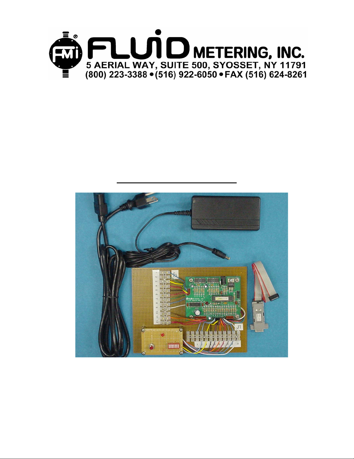
DEVELOPMENT KIT P/N ICST-01
SHOWN ABOVE
This kit is intended for help in setting up your required protocol for your FMI pump /
dispenser functions.
1
Page 2
Contents
1. SYSTEM SAFETY........................................................................... 3
2.
SYSTEM DESCRIPTION ................................................................ 3
2.1 FUNCTIONS
2.2 FEATURES
3. SYSTEM INSTALLATION.............................................................. 4
4.
WIRING SPECIFICATIONS ........................................................... 5
4.1 P/N ICST-01 Page 5
4.2 P/N ICST-01 OEM Page 6
5. PROGRAMS AND PROGRAMING.................................................7
5.1 Program Installation
5.2 Program Operation
6. SPECIFICATIONS........................................................................ 13
7.
TROUBLE SHOOTING................................................................. 14
TECHNICAL ASSISTANCE.......................................................... 14
8.
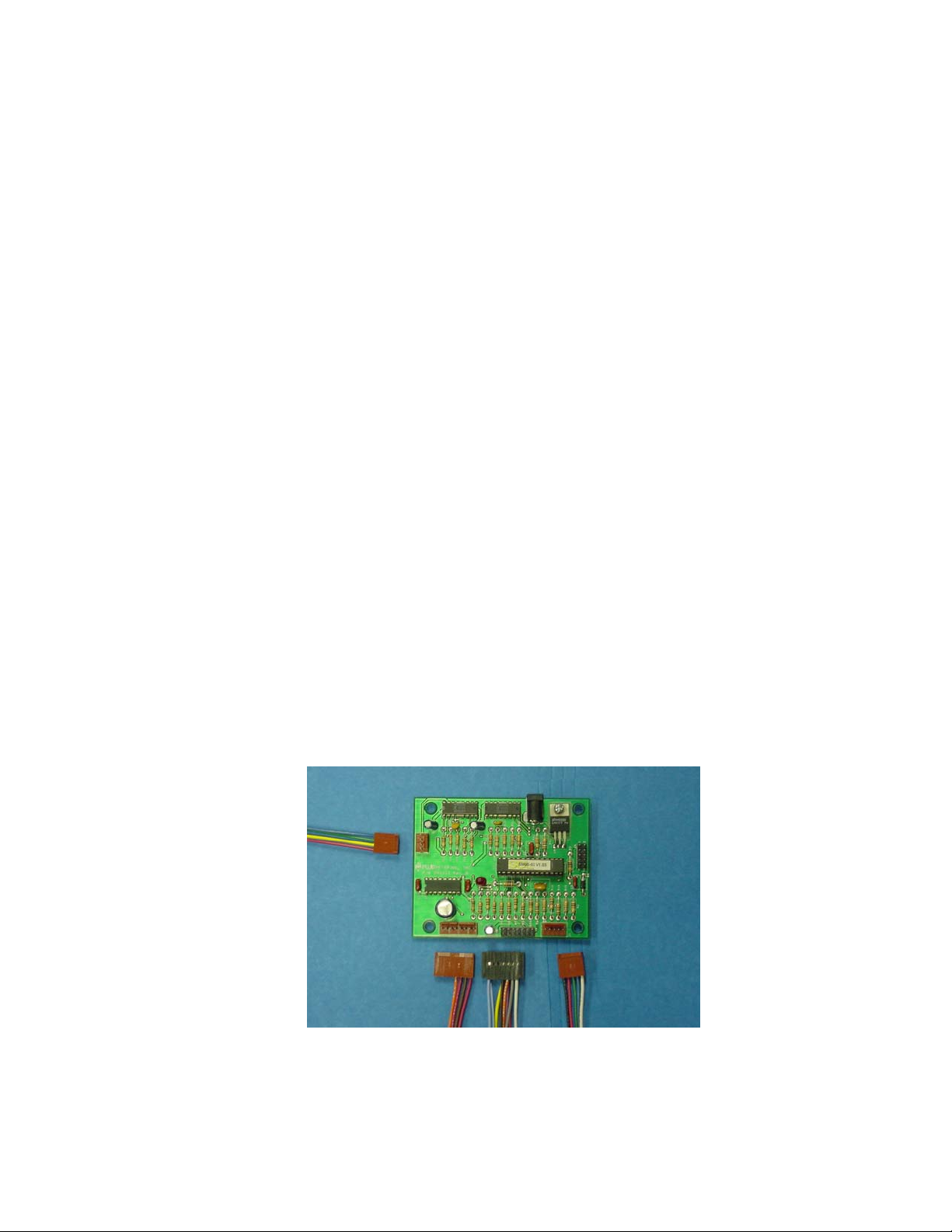
BOARD ALONE P/N ICST-01 OEM
SHOWN ABOVE
IN-ICST-01-07 2
Page 3
1. System Safety
CAUTION : To prevent power surge and damage to the board, apply and remove power by
the AC source of the power supply. DO NOT PLUG AND UNPLUG AT THE
BOARD.
CAUTION : To insure proper operation of the board be sure all wiring and connections are
correct and secure.
CAUTION : Keep fluids away from the electronics.
CAUTION : To prevent heat buildup in the motor, current to the motor should be reduced to
holding current or turned off between cycles.
2. System Description
The “ICST” is a programmable step motor control intended for use with FMI step motor
equipped pumps and dispensers. Using a computer programming adapter and exclusive ICSTPLE (program loader and editor) CD for Windows®, the operator can program the pump /
dispenser protocol that fits his application.
2.1 Functions
Fluid Metering Inc. can supply custom programs for the driver to fit most expected conditions.
Listed are a few of the functions of the driver boards programming.
Run: Clockwise or counter clockwise at fixed rate or through a profile table. The motor can be
accelerated and decelerated through a variable number of steps.
Stop: Stop can be programmed to actuate on either the leading or the trailing edge of the pumps
rotational flag. The stop can be also set to go any number of steps past the trip point. For
example if the program is set to stop on the trailing edge of the flag, going clockwise this would
stop the pump ½ way into the discharge stroke, the program can be instructed to go 100 steps
past the flag sense and stop at the bottom of the discharge stroke; without interrupting the
rotation. FMI standard (best) stop point is ½ way into the inlet stroke
Flow control: Program flow control includes the following; call, if, else, loop, goto, set, clear,
waitfor, repeat, run, halt, stop.
2.2 Features
Designed for maximum performance when mated to FMI 23 and 17 frame 1.8º step motors.
Most FMI step motor pumps come standard with a sensor and rotational flag that is aligned to the
pump piston. The rotational flag sensor outputs motor and or piston position to the driver.
All external connections to the driver board are via standard Waldom/Molex straight headers,
except the power input witch is a standard modular DC center positive receptacle. Development
kit has connections via barrier terminal blocks, except power input.
MOTOR OUTPUT POWER: Has three states, full power (1 Amp/Phase), low power (300
ma/Phase), or off. Power settings can be programmed to any state at any time. Ratings are ±
10%.
IN-ICST-01-07 3
Page 4

ACCESSORY OUTPUTS: Two dedicated power level outputs rated at supply voltage (24VDC)
and 150 milliamps each are available to drive external solenoids or relays.
TTL LEVEL INPUTS: Two dedicated TTL compatible high impedance, single ended, nonisolated, ground referenced, 5V inputs are provided. One is for Fluid Metering Inc. 5-wire optical
sensor. The other is high speed input capable recognizing an input pulse with a duration as little
as 4 Microseconds.
TTL LEVEL CONTROL: Seven TTL compatible I/O lines are available. These lines are current
limited to 5 milliamps each. All I/O lines are fully programmable.
3. System Installation
CAUTION : To insure proper operation of the board be sure all wiring and connection s are
correct and secure.
The “ICST” is a bi-polar driver only, set up to work half stepping only
stepping motor, this equals 400 steps per revolution. Speed and rotational calculations need to be
made from the 400 steps per revolution.
Stepping motors are made with different numbers of leads, there are 4, 6 and 8 lead motors. The
23 frame motor used on our general product line is an (8) eight lead motor. This motor, for the
best performance, works most efficiently when wired bipolar–series. The 17 frame motor is a (6)
six lead, and works most efficiently when wired half coil.
23 Frame Stepper.
FMI P/N 110746 (8lead)
Connector
Pin 6 RED wire is A Phase
Pin 1 YELLOW wire is A bar
Phase
Pin 8 GREEN wire is B Phase
Pin 3 BLUE wire is B bar Phase
Pins 2 & 5 BLACK & WHITE
terminated pair.
Pins 4 & 7 ORANGE & BROWN
terminated pair.
See Section 4, P/N ICST-01 or P/N ICST-01 OEM for the correct wiring, phase relationship, of the
motor to the driver. Motors shown are standard FMI pump drive motors.
For other motor wiring contact Fluid Metering.
FMI Sensor (STD. Optical Sensor) P/N 110569
This is a 5 lead inverted open collector output sensor. Signal goes high when the light source is
blocked. The pull-up and load resistors are built into the driver, so that the sensor can be directly
wired to the driver board.
RED wire is + V for the Ired LED.
BLACK wire is the ground for the Ired LED.
WHITE wire is the + V for the output.
GREEN wire is the ground for the output.
BLUE wire is the inverted open collector output to the controller.
17 Frame Stepper.
FMI P/N 110745 (6lead)
Connector
Pin 3 RED wire is A Phase
Pin 2 BLACK wire is A bar Phase
Pin 4 BLUE wire is B Phase
Pin 5 WHITE wire is B bar Phase
Pin 1 YELLOW wire is not used
Pin 6 ORANGE wire is not used
. For a standard FMI 1.8º
23 Frame Stepper (STRH).
FMI P/N 300615 (8 lead)
Used with FMI cable assembly
P/N 110711
Pin 1 ORANGE wire is A bar Phase.
Pin 2 & 5 WHITE/BLACK &
WHITE/ORANGE terminated pair.
Pin 3 YELLOW wire is B bar Phase.
Pin 4 & 7 WHITE/RED &
WHITE/YELLOW terminated pair.
Pin 6 BLACK wire is A Phase.
Pin 8 RED wire is B Phase.
IN-ICST-01-07 4
Page 5
NOTES ON TTL LOGIC: For interface to PLC or other type of control.
TTL (Logic High) ≥ 2.0 Vdc
TTL ( logic Low) ≤ 0.6 Vdc
Vin ( Absolute Maximum) = 5Vdc
Vin ( Absolute Mininum) = 0.0Vdc
Vin ( Logical High) = ≥ 3.5 Vdc.
Vin ( Logical Low) = ≤ 1.0 Vdc.
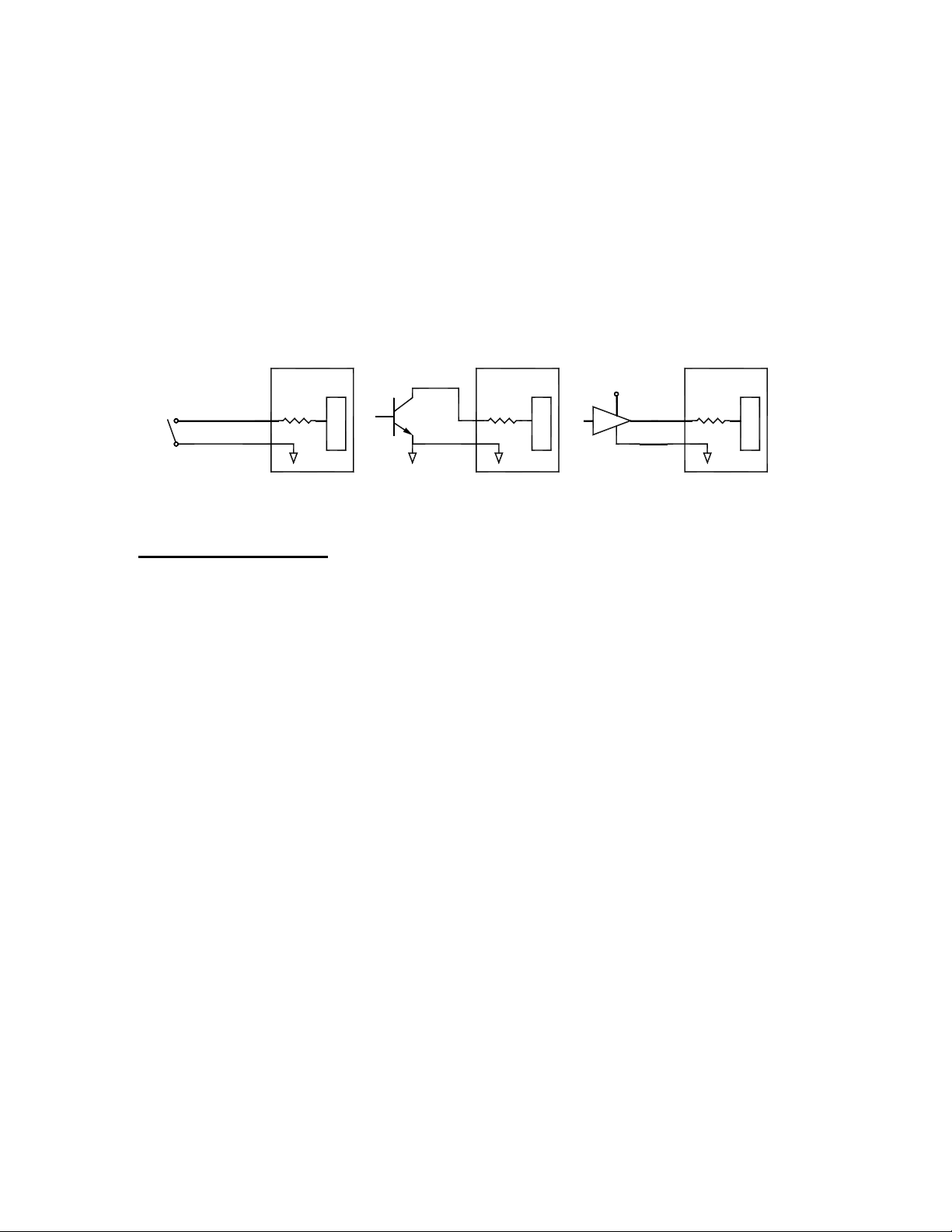
ACCEPTABLE INPUTS
5 Vdc
DRY CONTACT
4. Wiring Specifications
4.1 P/N ICST-01
Wiring for terminal strip marked J12:
Number 1 is the B bar phase to the motor.
Number 2 is the B phase to the motor. Note: See section 3 system
Number 3 is the A bar phase to the motor installation for motor wiring.
Number 4 is the A phase to the motor.
Number 5 is the Black wire from the sensor.
Number 6 is the Red wire from the sensor.
Number 7 is the Green wire from the sensor.
Number 8 is the Blue wire from the sensor.
Number 9 is the White wire from the sensor.
Number 10 is the Brown wire for Relay 1 (- side activated).
Number 11 is the Orange wire for Relay 2 (- side activated).
Number 12 is the 2 Red wires (+24 Vdc) for Relay power.
Wiring for terminal strip marked J11:
Numbers 1 and 2 are Ground, the Lt Blue wire two places.
Number 3 is the Push Button Switch (Activation Switch), the Yellow wire.
Number 4 is the Dip Switch 1 (I/O1), the Black wire.
Number 5 is the Dip Switch 2 (I/O2), the Purple wire.
Number 6 is the Dip Switch 3 (I/O3), the Orange wire.
Number 7 is the Dip Switch 4 (I/O4), the Red wire.
Number 8 is the Dip Switch 5 (I/O5, the Gray wire.
OPEN COLLECTOR
(OPEN DRAIN)
TTL or CMOS LOGIC
IN-ICST-01-07 5
Page 6

Number 9 is the Dip Switch 6 (I/O6), the Blue wire.
Number 10 is the Dip Switch 7 (I/O7), the White wire.
4.1 P/N ICST-01/ OEM
J1 I/O Connector
PIN # FUNCTION
Pin 1 Ground the Lt Blue wire.
Pin 2 Ground the Lt Blue wire.
Pin 3 + 24 V (From input power supply) NC
Pin 4 + 24 V (From input power supply) NC
Pin 5 +5 V (Do not recommend using this, loads the voltage regulator) NC
Pin 6 +5 V (Do not recommend using this, loads the voltage regulator) NC
Pin 7 Input 1 (Used as start signal) Yellow wire.
Pin 8 I/O 1 = Program PIN1 the Black wire.
Pin 9 I/O 2 = Program PIN2 the Purple wire.
Pin 10 I/O 3 = Program PIN3 the Orange wire.
Pin 11 I/O 4 = Program PIN4 the Red wire.
Pin 12 I/O 5 = Program PIN5 the Gray wire.
Pin 13 I/O 6 = Program PIN6 the Blue wire.
Pin 14 I/O 7 = Program PIN7 the White wire.
J2 Sensor Connector (STD. Optical Sensor) P/N 110569
PIN # FUNCTION
Pin 1 +5 V cc the White wire.
Pin 2 Signal from sensor to board the Blue wire.
Pin 3 Ground the Green wire.
Pin 4 +5 V ir the Red wire.
Pin 5 Ground the Black wire.
J3 Motor Connector
PIN # FUNCTION
Pin 1 A Phase the Red wire. Note: See section 3 system
Pin 2 A bar Phase the Yellow wire. installation for motor wiring.
Pin 3 B Phase the Green wire.
Pin 4 B bar Phase the Blue wire.
J4 Programming Connector
For use with the programming cable only. See pages 12 and 13 for details.
J5 Relay output Connector
PIN # FUNCTION
Pin 1 + 24 Vdc the Red wire.
Pin 2 Control to ground for RELAY1 the Brown wire.
Pin 3 + 24 Vdc the Red wire.
Pin 4 Control to ground for RELAY2 the Orange wire.
Pin 5 Not used + 24 Vdc NC
Pin 6 Not implemented NC
Pin 7 Not used + 24 Vdc NC
Pin 8 Not implemented NC
IN-ICST-01-07 6
Page 7

5. Programs and Programming
The “ICST” driver board is fully programmable and is designed to drive a low power stepper
motor through a pre-configured profile while exercising discrete outputs and responding to inputs
as necessary. The SCL (“Simplified Control Logic”) is a set of commands that allow stepper motor
position and timing control to be preset into a non-volatile memory. Board retains program in
memory after the board is powered down. Reapply power to the board and start the program.
Restart is usually through dedicated input. Note: If power is removed during a single revolution, a
partial revolution must be made to return to start “HOME” position. Fluid Metering Inc. can supply
custom programs for the driver to fit most expected conditions. More information about the
programming is available in the “PROGRAMMERS MANUAL” supplied on the CD in PDF format.
File names for the programs may not have more than eight (8) characters before the .SCL
extension.
The FMI “ICST-01” comes with ”ICST-PLE” Windows® multi-platform loading and editing
program CD, and programming adapter. Included are 4 general use programs to help you get
started. These programs are basic yet offer quick solutions to many simple dispensing/pump
application. These basic programs while fixed do offer some mods and tweaking functions.
A look at the basic programs:
900000 Test program to check board functions.
900000_1 Continuous in either direction at 300, 400, 450 or 500 spm
Purge and or Back flush at 500 spm
Single dispense with or without Suckback
Stall detect
900000_2 Dispensing – single or Multiple (continuous) by count
1 shot or multiple (2 to 6000)
Purge or Back flush at 500 spm
900000_3 Dispensing
Purge and or Back flush at 500 spm
1 shot aspirate
900000_4 Dispensing with output signal / Revolution
1,2 or 4 Dispenses / switch closure at 240 or 300 spm
Purge and or Back flush at 500 spm
1 shot aspirate
5.1 Program Installation
The “ICST-PLE” CD is setup to auto start. If your cdrom is not setup to auto start go to START
then RUN, Browse to the cdrom the CD is in click on setup then click open, click on OK to start
setup. Follow the on screen instructions. If the install did not place an icon on the desktop, go to
start menu, go to run, browse to Program Files/FirstStep/FirstStep.exe, click open then ok.
For specifications and attachment of the serial communications program adapter; FMI P/N
200277 refer to page 13.
Note: If for any reason the program becomes corrupt or non functional insert the CD, if the CD
auto starts say no to the installation, go to RUN browse to the disk and click on uninstall to
remove the program. After the program is removed browse to the setup and reinstall. CAUTION,
if you modified or are using a custom program you should move the files to another folder, the
uninstall will delete all the information in the current folder.
1,2 or 4 Dispenses / switch closure at 240 or 300 spm
IN-ICST-01-07 7
Page 8

Quick Start Screens:
Level 1, called “Pick and Run”, is designed to allow the least experienced user to select a
program from a list of documented programs, load that program into the hardware, and enable
program execution. Some operational parameters may be optionally adjusted at this level.
Level 2 – The “Target Inspector”, is designed for hardware checkout. On this level, an
engineer can see the target hardware the way the SCL controller sees it. Input lines can be
observed dynamically, output lines can be exercised individually and bi-directional signals
can be tested in both directions
IN-ICST-01-07 8
Page 9

Level 3 – This level “Building Blocks” is currently being developed.
Level 4 – This area is reserved for the advanced SCL programmer. Full control over all
features in the target is available to the user at this level. While SCL is considerably less
demanding than other micro-controller programming languages, it still requires a level of
“Logical” expertise that is better suited to someone with a programming background.
Main Screen:
Pull down menus: Files
Home
View
Toolbox menu is not functional for this
application.
Status bar shows target, program loaded
onto the board, status of the driver.
N = not connected
H = halted
R = running
Up arrow loads the programs.
Square halts the program execution
Right arrow starts the program
IN-ICST-01-07 9
Page 10

Pick and Run Screen:
Single click on a program in list brings the
program description into the description
window for review prior to loading.
Double click will auto load the program into the
board processor.
The program controls “Tweakable
parameters”associated with the program are
also shown.
Target Inspector Screen:
This screen shows boards I/O’s ,
This screen allows operator to check
And verify the operation of the boards
I/O functions.
Use in conjunction with supplied program
900000 to check the functionality of the
of the board. This program is loaded onto
the driver when shipped.
IN-ICST-01-07 10
Page 11

Advance Program Screen:
This screen by default opens with Project
Description, Program List and Program
Controls. Program List and Program controls
can be closed by clicking on the “X” button.
Use the mouse pointer to check the definitions
of the icons each has a pop up definition.
Two icons of note are the check and the bug.
The check icon: Checks the program for errors.
The bug icon: This brings up the Simulator/
Debugger screen. SEE THE NEXT SCREEN.
DEBUG/Simulation screen:
Open the Project Code screen by clicking
on the icon.
When using the step command the
program will highlite each command as it
steps through the program.
NOTE:
This is not a real time display. The
debugger is running in the computer
program not in the drivers on board chip.
The next step is to just push the buttons to see what happens. If the program stops running close it
and reopen it. The worst case is to crash the program, in this case use the CD and say no to the load
program prompt. Run the uninstall from the CD to remove the program from the drive and reinstall it.
When running the debugger This array shows the I/O’s
in step mode this bar will and the inputs as well as
advance through the timer the relays as they change
if a WAIT is in the program. States.
Click on this at a WAIT state
to go to the next line of code.
IN-ICST-01-07 11
Page 12

ICST Driver Board
Location of Headers and Location of Pin 1 on the Header
J4
Programing
Pin 1
Interface
Pin 1
J2
Sensor Input
J6
2
POWER INPUT
1
J4
J6
10
9
J2
J1
I/O Header
13114
Pin1
12
J1
J5
1
1
J3
Pin 1
J5
J3
Pin 1
Motor Output
IN-ICST-01-07 12
Relay Output
Page 13

6. Specifications
DRIVER BOARD
Electrical:
Input Voltage: 24 VDC at 2 Amps Min. ( J6 Power Jack Center Positive)
Mating Power Plug: 5.54mm OD 2.54mm ID 9.53mm Long
Output current: 1 Amp/Phase Max.
Stroke Rate: 500 RPM Max
. Drive mode is bi-polar for 2 phase stepping motors and is half stepped.
Duty Cycle: Intermittent and Continuous Duty.
Storage: -40º c to +125º c.
Operational: +20º c to +60º c.
Mechanical:
Circuit Board: Dimension: 3” [76,2 mm} X 3.75” [95,3 mm] X 1” [25,4 mm]
Mounting: 4 Holes: Ø 0.18 [4,57 mm]
2.50” [63,5 mm] X 3.13” [79,4] Pattern
DEVELOPMENT SYSTEM REQUIREMENTS:
100mhz Pentium or better
Windows 95, 98, ME, 2000
VGA monitor or better
10 megabytes of available disk space
8 megabytes of RAM
CD ROM drive
1 RS232 communications port: Standard 9 pin “D”
SERIAL COMMUNICATIONS WITH THE TARGET DRIVER:
RS232-C specification
9600 Baud
1 stop bit
No parity
1 Serial communications adapter cable, FMI P/N 200277
Ribbon cable orientation: Looking at the adapter so that the two LED’s are facing up the red wire
of the ribbon cable on the connector goes to pin 1 (indicated by arrow on the adapters’ mating
connector, the arrow is just outside of being in line with the LED).
Adapter cable attaches to J4 on the driver board. Red wire of the ribbon cable on the connector
goes to Pin 1 of J4; see page 12 for view of J4.
To verify port settings in “Windows” enable a session of “Terminal” or “Hyper-terminal”. Set the
communications settings to Parity-None, Flow control-none, Baud-9600, Data bits-8, Stop bits-1.
Select the appropriate COM port. With the terminal window selected, press the enter key and
verify that one of the LED’s on the programming adapter flashes. This indicates proper
connection and selection of the COM port.
NOTE: The program is by default setup to look for serial COM 1 if you do not have that COM port
available the port can be changed by clicking on the VIEW pull down and click on
Communications. Set the COM port to be used close the window and the program restart the
program.
IN-ICST-01-07 13
Page 14

7. Trouble Shooting
1. Be sure all connections are tight and secure.
2. Be sure all wiring is to the wiring specifications.
3. Be sure power is applied, typical 24 Vdc @ 2 A, 30 Vdc max.
4. Board fails to respond, chips on the board get hot: The major cause for total board failure
is hot swapping the power connector at the driver board this causes a power serge and may
also cause static discharge. The board is static sensitive.
5. Motor fails to rotate: Check motor wiring, check the program being run to be sure there is the
proper current setting, and check the program to be sure there sufficient acceleration ramp to
obtain the speed required.
6. Pump fails to stop: If the program is set up to stop the pump at a prescribed location and it
fails to stop at all. The most probable cause is a failure of the board seeing the flag signal. See
(Pump fails to stop in the correct location) for more information.
7. Pump fails to stop in the correct location: Check the program being run for programming
errors if the pump is programmed to stop at a place other the leading edge of the flag. Check
the sensor for function. This can be done with the ICST-PLE using the target inspector (Page
10), click select all than auto read. The sensor is INPUT 2 and should change state while
rotating the pump drive by hand. Checking the sensor itself is more difficult. If the sensor can
be removed from the pump body a volt meter across the blue wire connection and the green
wire connection will show the change in state if the light source is blocked and unblocked.
8. Failure to communicate with the driver board: Make sure the interface cable is installed
correctly, see page 13.
9. Program seems not to load properly: Loading a program repeatedly, making numerous
changes may cause the loader to fail to operate correctly. This is not usual case, but is a
software generated situation. To fix this, just go in the installed file directory (the place where
the program being loaded is located) and delete the files with the programs name with the file
extensions .LST and .BIN. Reload the program.
8. Technical Assistance
Please contact:
Fluid Metering Inc
Tel: 800-223-3388
5 Aerial Way, Suit 500
Syosset NY 11791 Tel: 516-922-6050
Email: pumps@fmipump.com Fax: 516-624-8261
IN-ICST-01-07 14
 Loading...