

Digital proportional radio control system
FS-lT4S
WARNING:
This product is only for 15 years
old or above
INSTRUCTION MANUAL

1
Thank you for purchasing our product, an ideal radio system for beginners or experienced users alike.
Read this manual carefully before operation in order to ensure your safety, and the safety of others or the
safe operation of your system.
If you encounter any problem during use, refer to this manual first. If the problem persists, contact your
local dealer or visit our service and support website for help:
www.flysky-cn.com/service.asp

2
FS-lT4S
Digital proportional radio control system
Table of contents
1. Safety ................................................................................................................................................4
1.1 Safety Symbols ................................................................................................................................................ 4
1.2 Safety Guide ....................................................................................................................................................... 4
2. Introduction ..................................................................................................................................... 6
2.1 System Features ................................................................................................................................................6
2.3 Transmitter Overview .................................................................................................................................... 7
2.3.1 Transmitter Antenna ............................................................................................................................ 7
2.3.2 Wheel and Trigger ................................................................................................................................. 7
2.3.3 Status Indicator ....................................................................................................................................... 8
2.3.4 Trims ........................................................................................................................................................... 8
2.4 Receiver Overview .......................................................................................................................................... 8
2.4.1 Receiver Antenna ................................................................................................................................... 8
2.4.2 Status Indicator ....................................................................................................................................8
2.4.3 Connectors .............................................................................................................................................. 8
3. Getting Started ................................................................................................................................ 9
3.1 Transmitter Battery Installation ................................................................................................................... 9
3.2 Connecting the Receiver and Servos ....................................................................................................... 9
4. Operation Instructions .................................................................................................................11
4.1 Power On ..........................................................................................................................................................11
4.2 Binding...............................................................................................................................................................11
4.3 Pre-use Check .................................................................................................................................................11
4.4 Adjusting Wheel Position ...........................................................................................................................12
4.5 Adjusting Wheel Position Stiffness
..............................................................................................................12
4.6 Trims ..................................................................................................................................................................12
4.7 Power Off .........................................................................................................................................................12
5. Home Screen ..................................................................................................................................13
6 Reverse Function .............................................................................................................................14
6.1 End Points Function ......................................................................................................................................14
6.2 Subtrim Function ..........................................................................................................................................14
6.2 Steering Exponential ..................................................................................................................................15
6.3 Steering Speed ................................................................................................................................................16
6.4 Steering Mix .....................................................................................................................................................16
6.5 Throttle Neutral ..............................................................................................................................................17
6.6 Throttle Exponential ......................................................................................................................................18
6.7 Throttle Curve .................................................................................................................................................18
6.8 A.B.S. ...................................................................................................................................................................19
6.9 Throttle Speed ................................................................................................................................................21
7 Throttle Middle ................................................................................................................................22
7.1 Throttle Idel Up ...............................................................................................................................................22
7.2 Engine Cut ........................................................................................................................................................22
7.3 Boat Mode ........................................................................................................................................................23
7.4 Break Mixing ....................................................................................................................................................23
7.5 Mixes ..................................................................................................................................................................23

3
7.6 Display Servos ................................................................................................................................................. 24
7.7 Race Timer ........................................................................................................................................................24
7.8 Keys Function ..................................................................................................................................................25
7.9 Models ...............................................................................................................................................................25
8.0 RX Setup ........................................................................................................................................27
8.1 Bind with a receiver .......................................................................................................................................27
8.2 RF std.: ADHDS 2A 2-way ............................................................................................................................27
8.3 Receiver PPM Output ..................................................................................................................................27
8.4 RX Battery Monitor ........................................................................................................................................28
8.5 Low Signal Alarm ..........................................................................................................................................28
8.6 FailSafe ...............................................................................................................................................................28
8.7 Display Sensors ...............................................................................................................................................28
8.8 Choose Sensors ..............................................................................................................................................29
8.9 Speed and Distance ......................................................................................................................................29
9 i-Bus Setup ......................................................................................................................................30
9.1 Servos frequency ..........................................................................................................................................30
9.2 Range Test .......................................................................................................................................................30
10.0 System .........................................................................................................................................31
10.1 Blacklight Timeout: (Time) ........................................................................................................................31
10.2 Backlight: (%) ................................................................................................................................................31
10.3 System Sound ...............................................................................................................................................31
10.4 Alarm Sound..................................................................................................................................................31
10.5 Auto Power Off .............................................................................................................................................31
10.6 Screen Calibration .......................................................................................................................................31
10.7 Units .................................................................................................................................................................32
10.8 USB Function ................................................................................................................................................32
10.9 Firmware Update .........................................................................................................................................32
11 Product Specification ...................................................................................................................33
11.1 Transmitter Specification .........................................................................................................................33
11.2 Receiver Specification ...............................................................................................................................33
Appendix 1 FCC Statement ..............................................................................................................34
4
FS-lT4S
Digital proportional radio control system
1. Safety
1.1 Safety Symbols
Pay close attention to the following symbols and their meanings. Failure to follow these warnings could
cause damage, injury or death.
Danger • Not following these instructions may lead to serious injuries or death.
Warning • Not following these instructions may lead to major injuries.
Attention • Not following these instructions may lead to minor injuries.
1.2 Safety Guide
Prohibited
Mandatory
• Do not fly at night or in bad weather like rain or thunderstorm. It can cause
erratic operation or loss of control.
• Do not use the product when the visibility is limited.
• Do not use the product on rainy or snowy days. Should any type of moisture
(water or snow) enter any component of the system, erratic operation and loss
of control may occur.
• Interference could cause loss of control. To ensure the safety of you and others,
do not operate in the following places:
▫Near any site where other radio control activity may occur
▫Near high tension power lines or communication broadcasting antennas
▫Near people or roads
▫On any pond when passenger boats are present
• Do not use this product when you are tired, uncomfortable, or under the
influence of alcohol or drugs. It may cause serious injury to yourself as well as
others.
• The 2.4GHz radio band is completely different from the previously used lower
frequency bands. Always keep your model in sight as a large object can block
the RF signal and lead to loss of control.
• Never grip the transmitter antenna when operating a model. It significantly
degrades the RF signal quality and strength and may cause loss of control.
• Do not touch any part of the model that generates heat during operating or
immediately after use, like the engine, motor, or speed control. These parts may
be very hot and can cause serious burns.

5
• Misuse of this product can lead to serious injuries or death. To ensure the safety
of you and your equipment, read this manual and follow the instructions.
• Make sure the product is properly installed in your model. Failure to do so may
result in serious injury.
• Make sure to disconnect the receiver battery before turning off the transmitter.
Failure to do so may lead to unintended operation and cause an accident.
• Ensure that all motors operate in the correct direction. If not, adjust the
direction first.
• Make sure the model flies within a certain distance. Otherwise, it would cause
loss of control.
6
FS-lT4S
Digital proportional radio control system
2. Introduction
The FS-iT4S is an 8-channel 2.4GHz AFHDS 2A digital proportional R/C system. It is compatible with cars
and boats.
2.1 System Features
The AFHDS 2A (Automatic Frequency Hopping Digital System Second Generation) developed and
patented by FLYSKY is specially developed for all radio control models. Offering superior protection
against interference while maintaining lower power consumption and high reliable receiver sensitivity,
FLYSKY's AFHDS technology is considered to be one of the leaders in the RC market today.
Bidirectional Communication
Capable of sending and receiving data, each transmitter is capable of receiving data
from temperature, altitude and many other types of sensors, servo calibration and i-BUS
Support.
Multi-channel Hopping Frequency
This systems bandwidth ranges from 2.4055GHz to 2.475GHz. This band is divided in
140 channels. Each transmitter hops between 16 channels (32 for Japanese and Korean
versions) in order to reduce interference from other transmitters.
Omni-directional Gain Antenna
The high efficiency Omni-directional high gain antenna cuts down on interference, while
using less power and maintaining a strong reliable connection.
Unique ID Recognition System
Each transmitter and receiver has it's own unique ID. Once the transmitter and receiver
have been paired, they will only communicate with each other, preventing other systems
accidentally connecting to or interfering with the systems operation.
Low Power Consumption
The system is built using highly sensitive low power consumption components,
maintaining high receiver sensitivity, while consuming as little as one tenth the power of a
standard FM system, dramatically extending battery life.

7
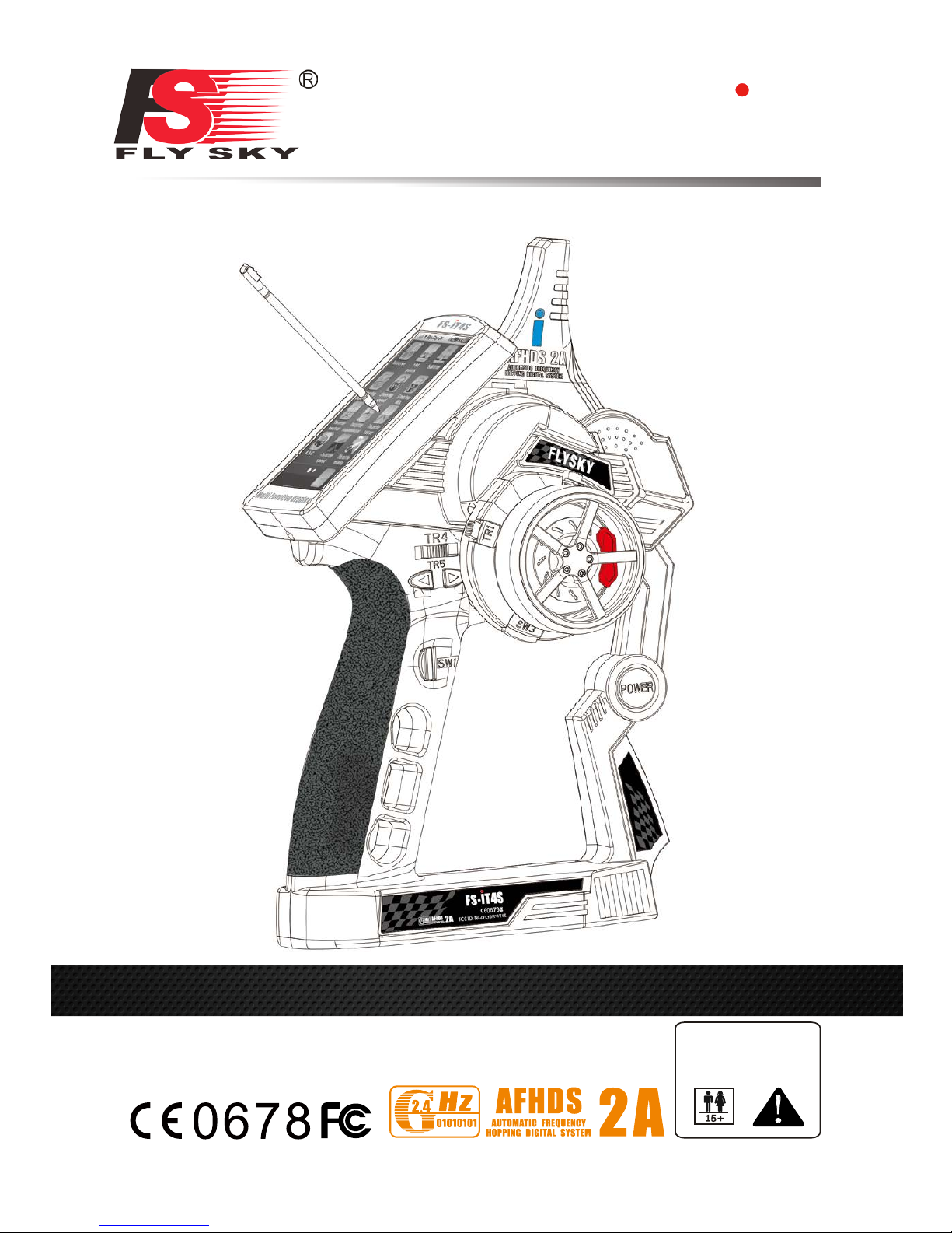
2.3 Transmitter Overview
Stylus
LCD
TR1
TR4
TR5
Sw1
Power
Wheel
Sw3
TR2
Antenna
2.3.1 Transmitter Antenna
Precautions:
□For best signal quality, make sure that the antenna is at about a 90 degree angle to the model. Do not
point the antenna directly at the receiver.
□Never grip the transmitter antenna when operating a model. It significantly degrades the RF signal
quality and strength and may cause loss of control.
2.3.2 Wheel and Trigger
The FS-iT4S has two main control inputs, the wheel and trigger.
□Wheel: Steering, use to control the direction of the model.
□Trigger: Used for acceleration, breaking and reverse.

8
FS-lT4S
Digital proportional radio control system
2.3.3 Status Indicator
The status indicator is used to indicate the power and working status of the transmitter.
□Off: the transmitter is powered off.
□Blue light: the transmitter is on and working.
□Flashing: the transmitter is binding.
2.3.4 Trims
There are 4 trims affecting surface functionality, one for throttle, steering, reverse and . Each time a trim is
toggled, the trim will move one step. It is possible to make quicker trim adjustments by holding the trim in
the desired direction. When the trim position reaches the middle, the transmitter beeps in a higher tone.
2.4 Receiver Overview
2.4.1 Receiver Antenna
Attention
• For best signal quality, ensure that the receiver is mounted away from motors
or metal parts. Also make sure that the antennas are mounted at a 90 degree
angle to each other.
2.4.2 Status Indicator
The status indicator is used to indicate the power status of the receiver.
□Off: the power is not connected.
□Lit in red: the receiver is on and working.
□Flashing quickly: the receiver is binding.
□Flashing slowly: the bound transmitter is off.
2.4.3 Connectors
The connectors are used to connect the parts of model and the receiver.
□CH1 to CH4 connectors are used to connect the servos, power or other parts.
□B/PPM connector is used to connect the bind cable for binding.
9
3. Getting Started
Before operation, install the battery and connect the system as instructed below.
3.1 Transmitter Battery Installation
Danger • Only use specified battery.
Danger • Do not open, disassemble, or attempt to repair the battery.
Danger • Do not crush/puncture the battery, or short the external contacts.
Danger • Do not expose to excessive heat or liquids.
Follow the steps to install the transmitter battery:
1. Open the battery compartment.
2. Insert a fully-charged battery into the compartment. Make sure that the battery makes good contact
with the battery compartment's contacts.
3. Replace the battery compartment cover.
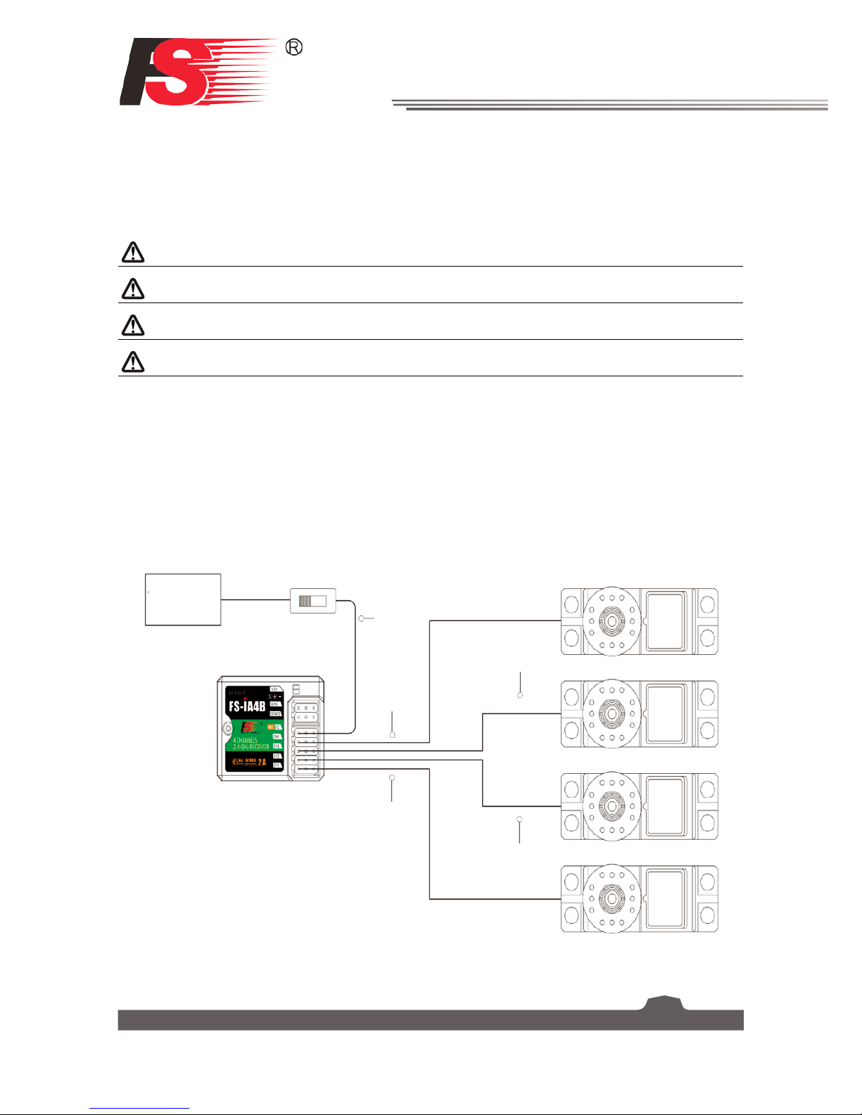
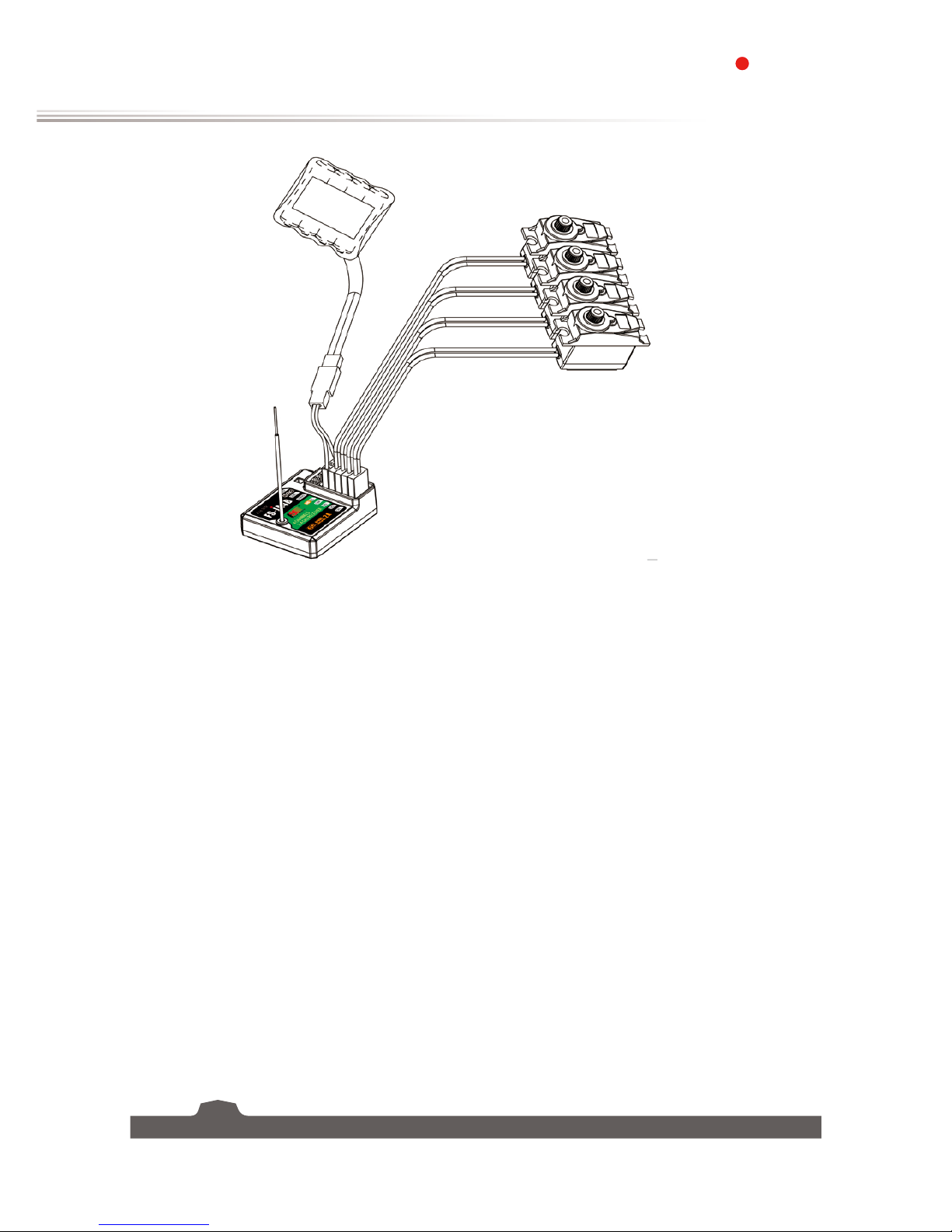
3.2 Connecting the Receiver and Servos
Connect the receiver and the servos as indicated below:
CH1
CH3
CH4
B/C
Switch (Optional)
Battery
CH2
10
FS-lT4S
Digital proportional radio control system
Battery
Servos
Receiver
 Loading...