

Fly Sky FS-I6S User Manual
FS-l6S
Copyright ©2015-2016 Flysky RC model technology co., ltd
USER MANUAL
Digital Proportional Radio
Control System
FCC ID:N4ZFLYSKYI6S

Thank you for purchasing our product, an ideal radio system for beginners or
experienced users alike.
Read this manual carefully before operation in order to ensure your safety, and
the safety of others or the safe operation of your system.
If you encounter any problem during use, refer to this manual first. If the problem
persists, contact your local dealer or visit our service and support website for help:
www.flysky-cn.com

Contents
1. Safety..................................................................................................................................1
1.1 Safety Symbols ........................................................................................................................................................................1
1.2 Safety Guide..............................................................................................................................................................................1
2. Introduction.......................................................................................................................2
2.1 System Features.......................................................................................................................................................................2
2.2 Transmitter Overview .......................................................................................................................................................................3
2.2.1 Transmitter Antenna ...................................................................................................................................................................4
2.2.2 Stick/Knob/Switch/Key...............................................................................................................................................................4
2.2.3 Status Indicator..............................................................................................................................................................................4
2.2.4 USB Simulator Mode...................................................................................................................................................................5
2.2.5 PS/2 Port .........................................................................................................................................................................................5
2.3 Receiver Overview ...................................................................................................................................................................5
2.3.1 Receiver Antenna..........................................................................................................................................................................5
2.3.2 Status Indicator..............................................................................................................................................................................5
2.3.3 Connectors ....................................................................................................................................................................................5
3. Getting Started ...............................................................................................................6
3.1 Transmitter Battery Installation.....................................................................................................................................................6
3.2 Connecting the Receiver and Servos .........................................................................................................................................6
4. Operation Instructions.....................................................................................................7
4.1 Power On....................................................................................................................................................................................7
4.2 Binding........................................................................................................................................................................................7
4.3 Pre-use Check...........................................................................................................................................................................7
4.4 Power Off....................................................................................................................................................................................8
5. System Interface...............................................................................................................9
5.1 Home Screen.............................................................................................................................................................................9
5.2 Timers.....................................................................................................................................................................................................9
5.3 Fly Mode..................................................................................................................................................................................10
5.4 TX/RX Battery ........................................................................................................................................................................11
5.5 Display Servos........................................................................................................................................................................11
5.6 Display Sensors......................................................................................................................................................................11
6. Function Settings............................................................................................................12
6.1 Reverse ....................................................................................................................................................................................12
6.2 End Points ...............................................................................................................................................................................12
6.3 Subtrim ....................................................................................................................................................................................12
6.4 Trims .........................................................................................................................................................................................13
6.5 Rate/Exp. .................................................................................................................................................................................13
6.6 Throt Curve ............................................................................................................................................................................13
6.7 Aux. Channels ........................................................................................................................................................................14
6.8 Mix ............................................................................................................................................................................................14
6.9 Failsafe......................................................................................................................................................................................14
7. System Settings...............................................................................................................15
7.1 RX Bind ....................................................................................................................................................................................15
7.2 Models .....................................................................................................................................................................................15
7.3 Output Mode .........................................................................................................................................................................15

7.4 Sticks Mode ............................................................................................................................................................................15
7.5 Throt Mode ............................................................................................................................................................................16
7.6 Sticks Adjust ...........................................................................................................................................................................16
7.7 Bri./Sound ...............................................................................................................................................................................16
7.8 Factory Reset .........................................................................................................................................................................16
7.9 Firmware Update ..................................................................................................................................................................17
7.10 About FS-i6S .......................................................................................................................................................................17
8. DIY Customization..........................................................................................................18
8.1 Throt Bracket Installation...................................................................................................................................................18
8.2 Throt Spring Installation.....................................................................................................................................................19
8.3 Swapping Gimbals................................................................................................................................................................20
8.4 Knob Bracket Installation...................................................................................................................................................21
8.5 Knob Spring Installation.....................................................................................................................................................22
8.6 Device Holder.........................................................................................................................................................................23
9. Product Specifications...................................................................................................25
9.1 Transmitter Specifications (FS-i6S) ...............................................................................................................................25
9.2 Receiver Specifications (FS-iA6B) ..................................................................................................................................25
10. Package Contents.........................................................................................................26
Appendix 1 FCC Statement .....................................................................................27
1
• Misuse of this product may lead to serious injury or death. To ensure the safety of
you and your equipment, read this manual and follow the instructions.
• Make sure the product is properly installed in your model. Failure to do so may
result in serious injury.
• Make sure to disconnect the receiver battery before turning off the transmitter.
Failure to do so may lead to unintended operation and cause an accident.
• Ensure that all motors operate in the correct direction. If not, adjust the direction
first.
• Make sure the model flies within a certain distance. Otherwise, it would cause loss of
control.
• Do not use the product at night or in bad weather like rain or thunderstorm. It can
cause erratic operation or loss of control.
• Do not use the product when visibility is limited.
• Do not use the product on rain or snow days. Any exposure to moisture (water or
snow) may cause erratic operation or loss of control.
• Interference may cause loss of control. To ensure the safety of you and others, do
not operate in the following places:
• Near any site where other radio control activity may occur
• Near power lines or communication broadcasting antennas
• Near people or roads
• On any body of water when passenger boats are present
• Do not use this product when you are tired, uncomfortable, or under the influence
of alcohol or drugs. Doing so may cause serious injury to yourself or others.
• The 2.4GHz radio band is limited to line of sight. Always keep your model in sight as
a large object can block the RF signal and lead to loss of control.
• Never grip the transmitter antenna during operation. It significantly degrades signal
quality and strength and may cause loss of control.
• Do not touch any part of the model that may generate heat during operation, or
immediately after use. The engine, motor or speed control, may be very hot and can
cause serious burns.
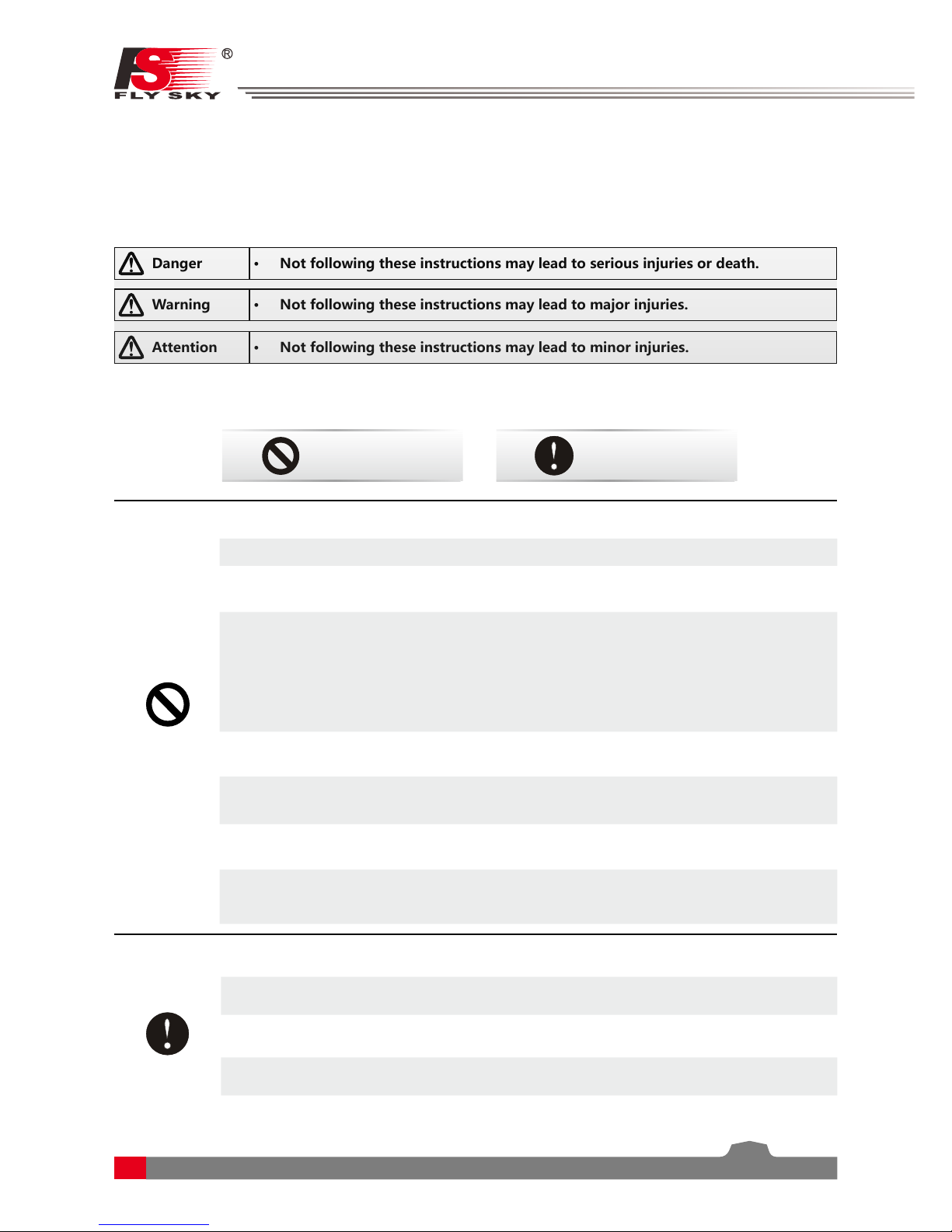
Prohibited Mandatory
1.
Safety
1.1 Safety Symbols
Pay close attention to the following symbols and their meanings. Failure to follow these warnings could cause
damage, injury or death.
1.2 Safety Guide
Warning • Not following these instructions may lead to major injuries.
Danger
• Not following these instructions may lead to serious injuries or death.
Attention
• Not following these instructions may lead to minor injuries.
Digital Proportional Radio Control System
2
FS-l6S
2.
Introduction
The FS-i6S transmitter and iA6B receiver constitute a 6 channel 2.4GHz AFHDS 2A digital proportional
computerized R/C system. This system supports quadcopter.
2.1
System Features
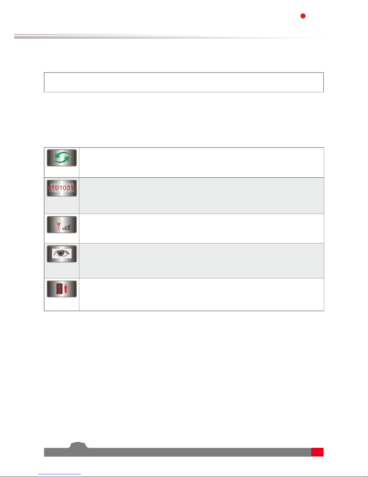
The AFHDS 2A (Automatic Frequency Hopping Digital System Second Generation) developed and patented
by FLYSKY is specially developed for all radio control models. Offering superior protection against interference
while maintaining lower power consumption and high reliable receiver sensitivity, FLYSKY's AFHDS technology
is considered to be one of the leaders in the RC market today.
Bidirectional Communication
Capable of sending and receiving data, each transmitter is capable of receiving data from
temperature, altitude and many other types of sensors, servo calibration and i-BUS Support.
Multi-channel Hopping Frequency
This systems bandwidth ranges from 2.4055GHz to 2.475GHz. This band is divided in 140
channels. Each transmitter hops between 16 channels (32 for Japanese and Korean versions) in
order to reduce interference from other transmitters.
Omni-directional Gain Antenna
The high efficiency Omni-directional high gain antenna cuts down on interference, while using
less power and maintaining a strong reliable connection.
Unique ID Recognition System
Each transmitter and receiver has it's own unique ID. Once the transmitter and receiver have
been paired, they will only communicate with each other, preventing other systems accidentally
connecting to or interfering with the systems operation.
Low Power Consumption
The system is built using highly sensitive low power consumption components, maintaining
high receiver sensitivity, while consuming as little as one tenth the power of a standard FM
system, dramatically extending battery life.
33
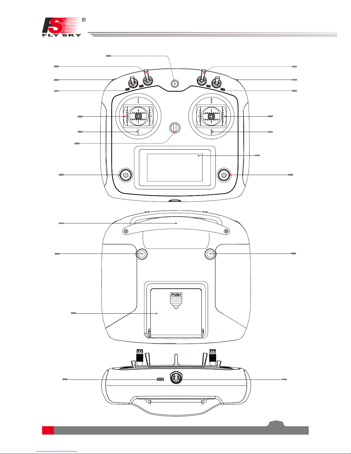
2.2 Transmitter Overview
VrA
Rudder/Aileron
Throttle/Elevotor
Power
Neck strap eye
SwA
SwB SwC
VrB
SwD
Device holder mounting point
Handle
Key 2
Battery cover
USB port
Rudder/Aileron
Throttle/Elevotor
Capacitive touch screen
Power
Key 1
PS/2 port
Digital Proportional Radio Control System
4
FS-l6S
2.2.1
Transmitter Antenna
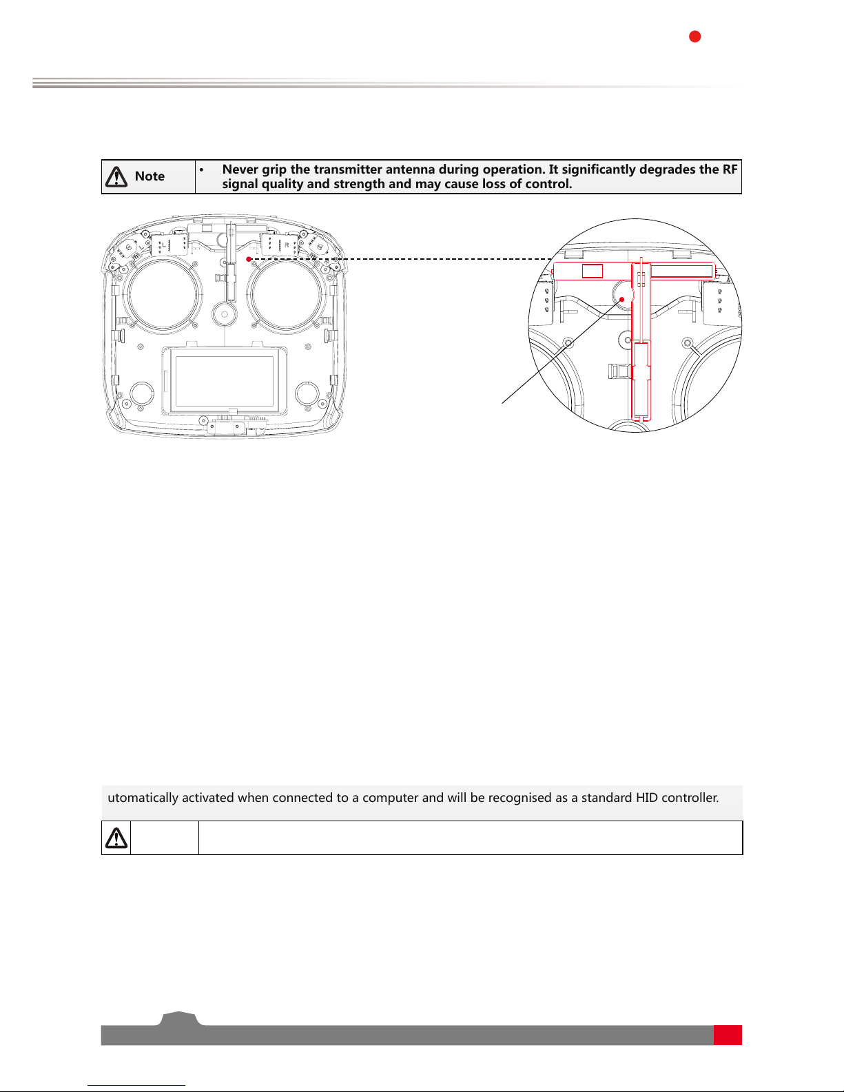
Note
• Never grip the transmitter antenna during operation. It significantly degrades the RF
signal quality and strength and may cause loss of control.
2.2.3
Status Indicator
The status indicator is used to indicate the power and working status of the transmitter.
• Off: The transmitter is powered off.
• Blue light: The transmitter is on and working.
2.2.5 PS/2 Port
This port enables PPM output.
2.2.2 Stick/Knob/Switch/Key
The FS-i6S has 2 sticks, 2 knobs, 4 switches and 2 keys.
• Stick: Used to control aileron, elevator, throttle and rudder, or controls aux. channels.
• Switch: Controls aux. channels or timer.
• Knob: Used to control aux. channels.
• Key: Used to control aux. channels or timers.
The FS-i6S transmitter has a built-in dual omnidirectional antenna.
2.2.4 USB Simulatior Function
The system can be connected via a USB cable to a computer for use as a HID device. This function is
automatically activated when connected to a computer and will be recognised as a standard HID controller.
Caution
• If the computer does not recognise the transmitter unplug and reconnect the USB
cable.
Antenna
5
2.3 Receiver Overview
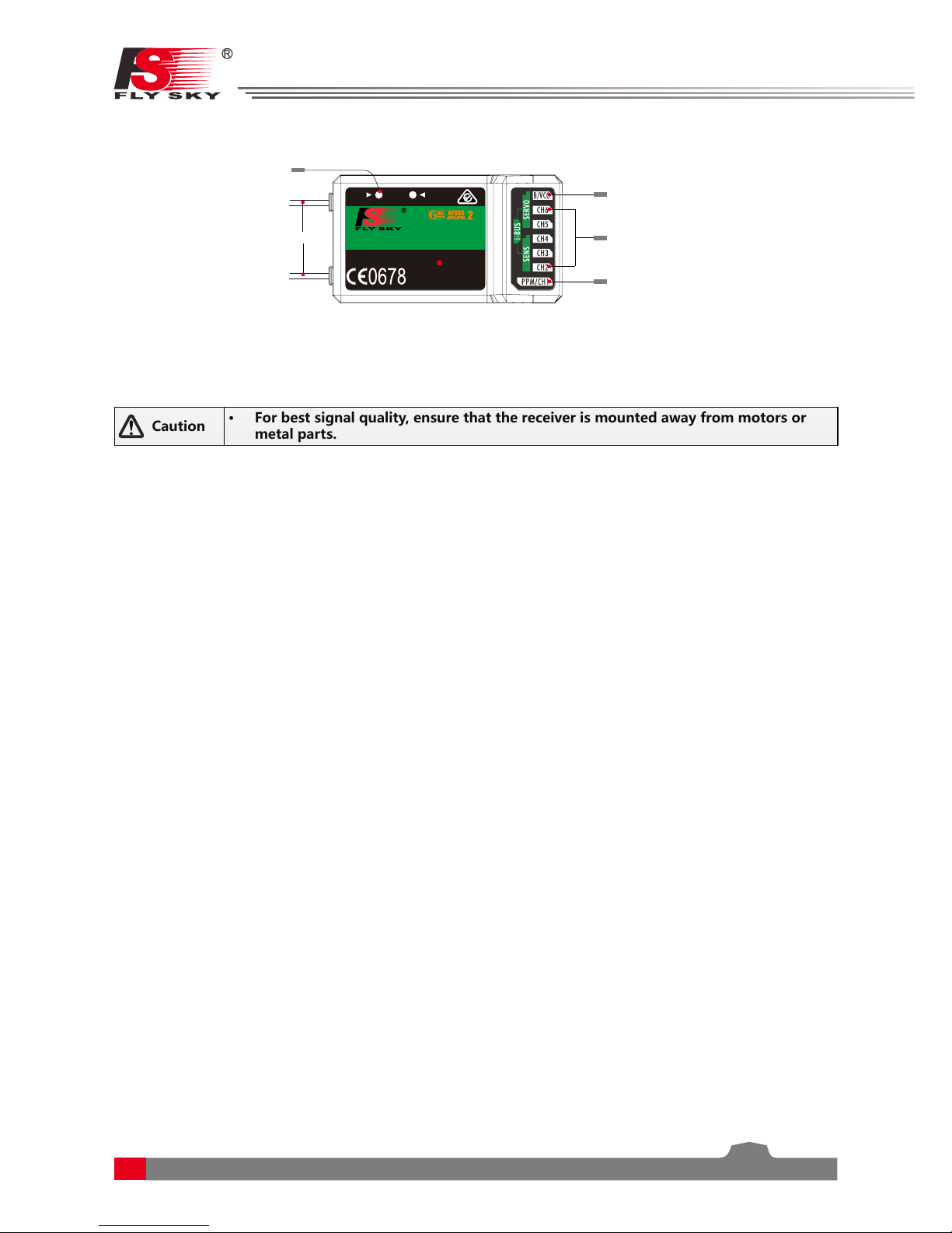
Caution
• For best signal quality, ensure that the receiver is mounted away from motors or
metal parts.
2.3.3
Connectors
The connectors are used to connect the parts of model and the receiver.
• PPM/CH1: Connection of CH1 or PWM output signal.
• CH2 to CH6: Used to connect the servos, power or other parts.
• B/VCC: Used to connect the bind cable for binding, and the power cable during normal operation,in the
range of 4.0-8.4V.
• SERVO: For connecting an i-BUS receiver.
• SENS: For connecting sensors.
2.3.2
Status Indicator
The status indicator is used to indicate the power and working status of the receiver.
• Off: The power is not connected.
• Lit in red: The receiver is on and working.
• Flashing quickly: The receiver is binding.
• Flashing slowly: The bound transmitter is off or signal is lost.
2.3.1
Receiver Antenna
The FS-iA6B has a dual 26mm omnidirectional antenna.
Antenna
Bind/VCC
Ch2- 6
PPM/CH1
A
LED
UP
DATE
FS-IA6B
6 VER
2.4
GHz
4.0-8.4V/DC
FCC ID:N4ZFLYSKYIA10
CHANNE
L
Status indicator
RECEI
Digital Proportional Radio Control System
6
FS-l6S
3.
Getting Started
Before operation, install the battery and connect the system as instructed below.
3.1 Transmitter Battery Installation
Danger
• Only use specified battery (X4 AA batteries).
Danger
• Do not open, disassemble, or attempt to repair the battery.
Danger • Do not crush/puncture the battery, or short the external contacts.
Danger
• Do not expose to excessive heat or liquids.
Danger
• Do not drop the battery or expose to strong shocks or vibrations.
Danger
• Always store the battery in a cool, dry place.
Danger
• Do not use the battery if damaged.
Follow the steps to install the transmitter battery:
1. Open the battery compartment.
2. Insert 4 fully-charged AA batteries into the compartment. Make sure that the battery makes good contact
with the battery compartment's contacts.
3. Replace the battery compartment cover.
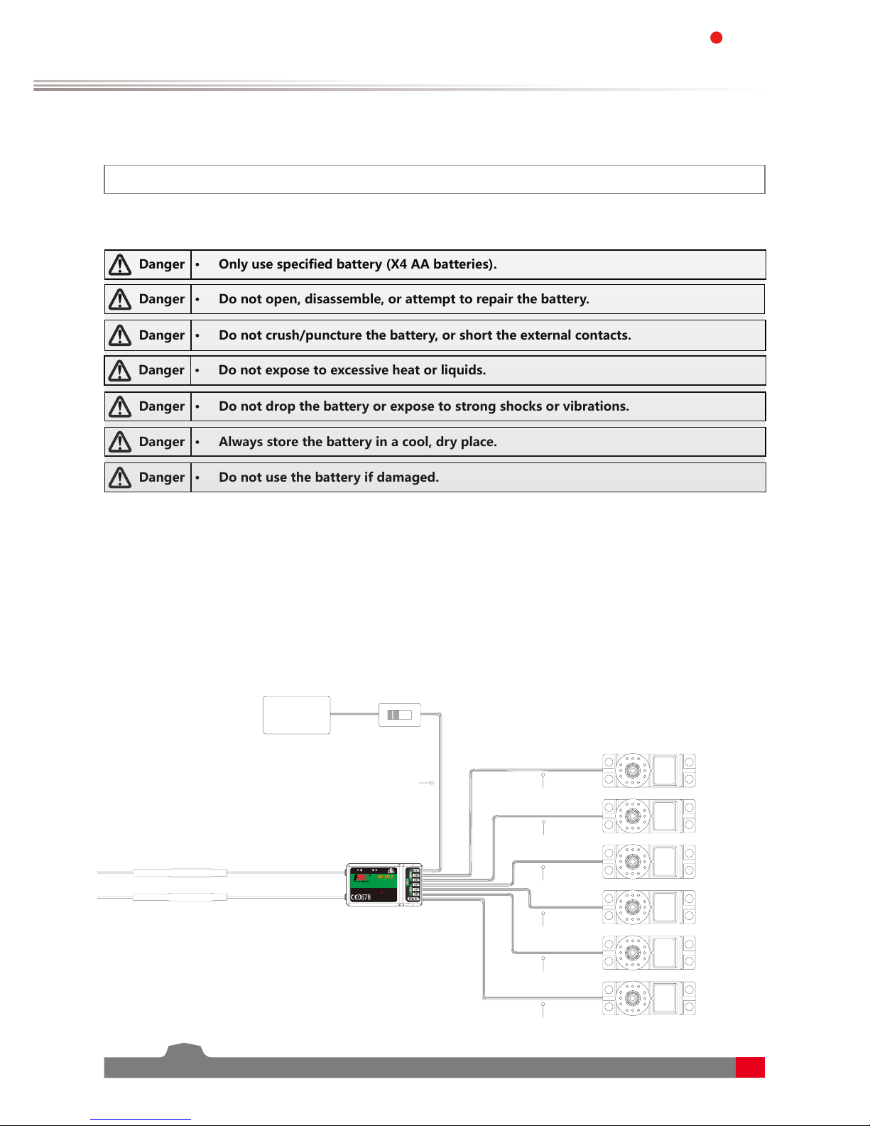
3.2 Connecting the Receiver and Servos
Connect the receiver and the servos as indicated below:
A
LED
UP
DATE
FS-IA6B
6 VER
2.4
GHz
4.0-8.4V/DC
FCC ID:N4ZFLYSKYIA10
Rudder servo
Throttle servo
Elevator servo
Aileron servo
CHANNE
L
CH1
CH2
CH3
CH4
CH5
CH6
B/Vcc
Switch (Optional)
Battery
RECEI
 Loading...