

Page 1

6 CHANNEL RADIO CONTROL SYSTEM
INSTRUCTION MANUAL
Http:www.flyskychina.com
FS-CT6A
MODEL:
Copy right 2007@flysky co.,ltd
Digital propotional radio control system
Page 2

Menu
1. Introduction. .. . .. . .. . . .. . .. . .. . .. . . .. . .. . .. . .2
2. Services... . .. . .. . . .. . .. . .. . .. . . .. . .. . .. . .. . . 2
3. The special symbols. .. . .. . .. . .. . . .. . .. . .. . .. . . 3
4. safty guides. . . .. . .. . .. . .. . .. . . .. . .. . .. . .. . . .. 3
8 . . Each part of the transmitter. . .. . . .. . .. . .. . .. . . .. 6
9 . Receiver and server connectivity.. . .. . .. . .. . . .. . .7
13 . Transmitter function notes(Heli). .. . .. . . .. . .. . 1 2
14 . Transmitter function notes(Plane). . . .. . .. . .. . .1 6
15 Professional terminology . .. . . .. . .. . .. . .. . . . . . .. 1 9
5. Power charging. .. . .. . .. . . .. . .. . .. . .. . . . . . .. . .4
1 0 . 2 .4 G Operation Notes. . .. . .. . .. . .. . . . . . .. . .. . 8
10. 01 Matching.... . .. . .. . .. . . . . . .. . .. . .. . . . 8
10. 02 Boot.. . . .. . .. . .. . .. . . . . . .. . .. . .. . . . . . 8
10. 03 Shutdown.... . .. . .. . .. . . . . . .. . .. . .. . . . 9
13. 01 System function options.. . .. . .. . . . . . .. . .. 12
1 2 . .. . . .. . .. . .. . .. . . 1 1Computer software installation
13. 02 System function settings... . . .. . .. . .. . . . . . 13
13. 03 Switches and potentiometer settings. . .. . .. . .. 15
14. 01 System function options.. . .. . .. . . . . . .. . .. 16
14. 03 Switches and potentiometer settings. . .. . .. . .. 18
14. 02 System function settings... . . .. . .. . .. . . . . . 17
2. 4G 6 Channel remote system
1
FS-CT6A
Model:
Notes
16 Packaging with content list. .. . . .. . .. . .. . .. . . . . . 2 0
6 . Transmitter parameters. .. . .. . .. . . .. . .. . .. . .. . . .5
7 . Receiver parameters.. . . .. . .. . .. . .. . . . . . .. . .. . .5
1 1 . .. . . .. . .. . .. 1 0Computer hardware connection steps
Page 3

2. 4G 6 Channel remote system
2
FS-CT6A
Model:
Notes
1.Introduction
2.Services
If you found any problems during the operation process, please refer to the manual.
If the problem still exist, you could contact our dealers to found out the way to solve.
And you could also log on to our website service center:
HTTP:WWW. FLYSKYCHINA. COM
Thank you for choosing 2.4 G ratio remote control digital products, if you are the first
time to use this type of products, please read this statement carefully and strictly in
accordance with the requirements of operation. You could refer to the Manual if you
meet any problems during the operation . Please well keep the manual after use
because you might have to use it again next time. Once again, thanks for buying our
products, and hope that it brings happiness to you.
Page 4
3.The special symbols
2. 4G 6 Channel remote system
3
FS-CT6A
Model:
Notes
Please pay attention to the following symbols when it appears on the manual,
and read carefully.
Danger:
If the oper ator does not oper ate by fol low ing the inst ruct ions,
the oper ator may lead to ser ious injur ies, even Mortal dang er.
Warning:
If the operator does not operate by following the inst ructions,
the operator may lead to se rious injuries, eve n Mortal danger.
Attentio n:
If the oper ator do es no t op er at e by fol lowing the inst ruct ions,
the op erat or may lea d to mino r inj ur ies, bu t ge ne ral ly it will
not cau se ser iou s inj ur ies to the op er at or.
Prohibition
Mandatory
4.Safty guides
Do not fly in bad weather such as rainy or thundering to assure the
safety of you and others.
Before you fly, please ma ke sure the moveme nt of server are correspond
with the direction of joystick. If inconsistent, please adjust before fly.
You need to turn the throttle channel(ch3) and inching switch
to the lowest before you use. Then switch on the transmitter power
(red light or flashing means low battery),finally connect the receiver.
The Sequence to shut down is first turn the receiver power and the
transmitter power.
If the above operations are reverse, it might lead to uncontrolled and
cause accident.
Page 5
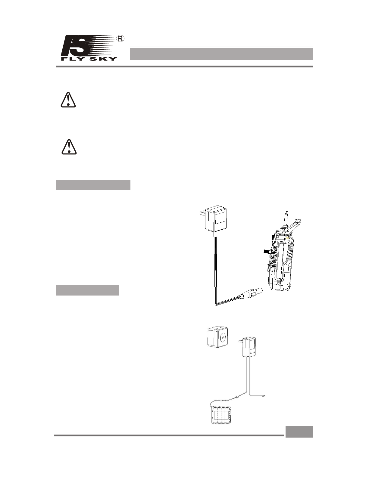
5.Battery charging notes
If you are using a nickel-cadmium, nickel-metal hydride batteries for
recharging, please use our company dedicated charger. If the electrical current
is too large and it may lead to temperature over-heated and cause fire burning
accident. Please cut off the power supply immediately after recharging. Please
take out the battery from the transmitter when you are not using it within a
period, it is because the battery may damage the aircraft batteries, thus being
exposed.。
Transmitter charger:
1. Install the battery to transmitter with correct direction, and cover it.
2. Connect the charger to the main connector.
3. Connect the charger to the transmitter
Connector.
4. Cut off the power supply immediately after
Recharge completed.
If your transmitter, receiver using a nickel-cadmium, nickel-metal hydride
rechargeable battery, you have to well-check before you fly. If lack of
electricity, it could happen those phenomenon like inadequate control or out of
control, resulting accident. So please charge immediately when low in battery.
Receiver charger:
1. Connect the charger to the main connector.
2. Connect the Rechargeable receiver with battery charger
3. Recharge completed, cut off the power supply immediately.
2. 4G 6 Channel remote system
4
FS-CT6A
Model:
Notes
Page 6

2. 4G 6 Channel remote system
5
FS-CT6A
Model:
Notes
6.Transmitter parameters
7.Receiver parameters
*Channel:6
*Frequency band: 2.4GHz
*Power resource:1.5V*4 "AA" Battery
*Program type: GFSK
*Modulation type: FM
*RF Receiver sensitivity:-76db
*Static current: ≤8 5 mA
*Size:45*23*13. 5mm
*Size:25*16.8* 6.5m m
*Weigth: 12g
*Color: G ray semi-transp arent
*Antenna length:26mm
*Channels:6
*Charger port: Yes
*Frequency band: 2.4GHz
*Simulator port: PS-2
*Power resource:1.5V*8 "AA" Battery
*Program type: GFSK
*Modulation type:FM
*RF power:1 9 d b
*Static current: ≤250mA
*Voltage display type:LE D
*Size:189*97*218mm
*Weigth: 575g
*Color: black
*Antenna length:26mm
*Heli-140/Heli-120/He li-90/Acro
*Sub Trim:Yes
*Thro Cuv: Programmable
*Pith Cuv: Programmable
*Support multiple user mode l
*S upport trim movement
*Support rudder angle overt urned
*Support rudder angle adjus tment
*S upport b oth hand softwa re adjustment
*S upport swashplate adju stment
*Support programmable cha nnel output
Page 7
2. 4G 6 Channel remote system
6
FS-CT6A
Model:
Notes
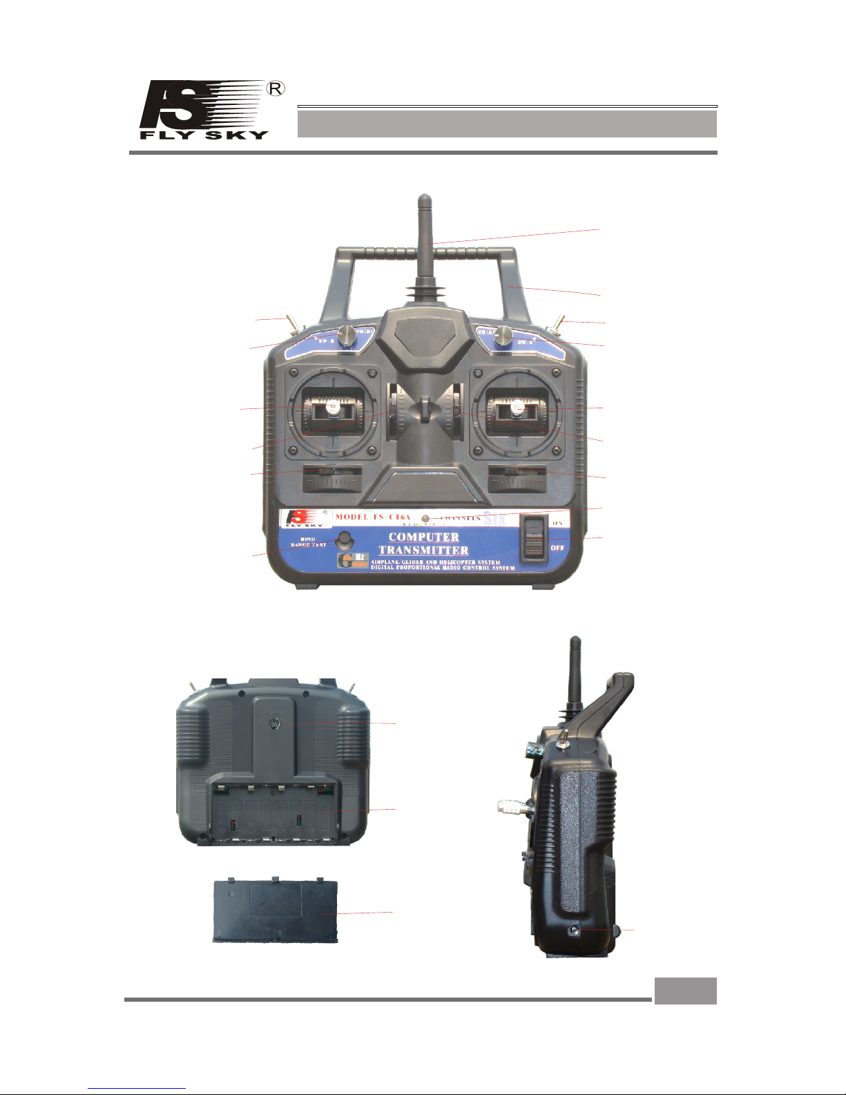
8.Each part of the transmitter
Antenna
Handle
Switch A
Switch B
Pit Trim
HOV.Pit
Aileron
throttle stick
Direction
Elevator
Aileron trim
Throttle trim
Power switch
Power indicator
light
Rudder trim
Elevator trim
Charger
Port
Simulant
connecter
Battery
cover
Battery
box
Front
Back
Side
Matching
(yards) keys
Page 8

9.Receiver and server connectivity
2. 4G 6 Channel remote system
7
FS-CT6A
Model:
Notes
Receiver Module
CH1
Ch2
Ch3
Ch4
Ch5
Ch6
Main receiver
Battery
When installing the receiver please make sure that
two items showed 90 degree angle.
Receiver
Module
Main receiver
Page 9

10.2.4G Operation notes
This is 2.4 G Frequency model products make of automatic address code.It use digital
transmission mode, and this prevent outside interference effective active and passive.
10. 01 Matching (code)
1. Install the battery to 2.4G transmitter and shut it down.
2 . ( 1)。Insert the matching lines to the channel Bat port of the receiver. Figure.
3 . Connect the receiver battery to any one of the channel port, on the same time the
two LED are flashing and this means the receiver are going to the match status.
4 . Press and hold the button on the transmitter, and then switch on the power supply.
6 . Release the match button on the transmitter, take out the match line.
5 .
( )
Observe the LED on the receiver, if found that the LED is not flash anymore and
that means successful matched. This process about 10s
7 . Install the server and then test.
8 . If the tests fail, please repeat the action above.
9 . If the tests success, then insert the power supply port into BAT, match complete.
(The above ways of match is only suitable on FLYSKY 2.4G products)
Our products are well matched in the factory, you do not need to match by yourself.
But if your are going to match the receiver with other transmitter, please follow the
following steps:
Match line
Match key
Figu re 1
10. 02 Boot
1. Connect every part.
2. Switch on the power supply.
3. Connect the power supply.
4. Receive LED light solid.
5. Finish and use.
2. 4G 6 Channel remote system
8
FS-CT6A
Model:
Notes
Page 10

2. 4G 6 Channel remote system
9
FS-CT6A
Model:
Notes
Boot
1. Cut off the receiver power supply.
2. Cut off the transmitter power supply.
Tx power ON
Tx power off
Rx power ON
Rx power off
Shut down
10. 03 Shut down:
Page 11

2. 4G 6 Channel remote system
10
FS-CT6A
Model:
Notes
11.Computer hardware connection steps
When you buy the CT6 series remote systems, with a programming line you can set up
the program by your own, this will bring you happiness. You have to follow the
following steps when you process the program setup:
1. Install the battery to the transmitter and switch on the power.
2. Plug in the programming line to the transmitter port.
3. Plug in the other head of programming line to computer.
4. Launch the software program T6CONFIG.EXE.
5. Click on setting button, select programming lone port.
6. Click on GETUSER button, import the transmitter data to pc.
7. Apply programmable settings on the existing parameters.
Page 12

2. 4G 6 Channel remote system
11
FS-CT6A
Model:
Notes
12. Computer software installation
FS-CT6A use the new computer programmable model design, every function of
transmitter can be setup by computer. It makes you enjoy the fun of high-tech models.
12.01 PC software download:
You can download from our website : WWW.FLYSKYCHINA. COM
12.02 PC software installation:
12.03 PC software application:
1. Install driver software:FS-CT6DRIVER001. EXE
2. Install application software:FS- CT6SOFTWARE. EXE
3. Restare computer.
4. Installation completed.
Application interface
3. Left double-click the application icon and show up the following
screen.
1. Install the battery to the transmitter and switch on the power.
2. Connect the transmitter, programming line and pc.
Page 13

2. 4G 6 Channel remote system
12
FS-CT6A
Model:
Notes
13.Transmitter function notes(Heli)
13. 01 System function option:
Connect the transmitter programming line with pc, switch on the transmitter and
application software. If you choose these types of heli(HELI90、HE LI120、HELI140)
the following interface will appear:
Channel output
display
System function
option
System function
setting
Switch program
setting
Left click the ‘SETTING’ button, the screen on the right
will appear, this system function is us e for the
programming line USB port selection, it improves the
communication of Transmitter and PC. If select wrongly,
the channel output display will not have any data changes
and all other settings are invalid.
Press ‘ok’ button after finished selecting.
Left click the ‘HELP’ button on the interface, and the
interface on the right will appear, this interface offer
you some services information.
GETUSER:Import the transmitter data to pc.
When programming, please use GETUSER button to transfer the data to PC after
make sure the setting function, this prevent the data overwrite.
Page 14

2. 4G 6 Channel remote system
13
FS-CT6A
Model:
Notes
Left click the ‘SAVE’ button on the interface, the screen on the rig ht
will appear, th is f unction is for save all your settings. in theory, you
can set up numerous types an d sa ve .
You can give it a name, and left click t he ‘ sa ve ’ button to save.
Left click the ‘OPEN’ button on the main interface, the screen on the
right will appear, th is system function is for the parameters setting.
Left click the ‘save’ button after select finished.
Left click the 'ENDPOINT ’ button on the interface, the screen on th e
right will appear, th is function is use for adjust the movement of
server to a suitable angel f or a b et te r control.
Each server a re allowed to ad just Individual , it has two parts: left h al f
part and right half part. Adjusted va lu e f ro m 0 % t o 1 00%, the number
can be directly enter from t he k ey bo ard.
Left click the 'ok' button t o fi ni sh t he adjustment.
Left click the 'cancel' bu tt on t o re store.
Left click the 'REVERSE’ button on the interface, the screen on the
right will appear, th is function is use for change the direction of server
movement, it keeps the tra ns mi tt er control direction correspond to the
server.
Left click the channel you w an t to c ha nge.
Click 'ok' button to finis h th e ad ju stment.
Left click the 'SUBTRIM’ button on the interface, the screen on the
right will appear, th is function is use for adjustment for single server
for a better control, impr ov e th e ya rage of model.
Each server are allowed to a dj us t In dividual, Adjusted value from 120 to 120. Number can be dire ct ly e nt ered from the keyboard.
Click 'ok' button to finis h th e ad ju stment.
13. 02 System function settings
Page 15

2. 4G 6 Channel remote system
14
FS-CT6A
Model:
Notes
Left click the 'DR' button o n the interface, the screen on the right will
appear, this function is use for Double ratio co ntrol of CH1\CH2\CH4
channel. It gives you the best c on trol of the model. This function offer
the great help to beginner.
CH1\CH2\CH4 are allowe d to a dj ust Individual, Adjusted value from
0% to 100%. Number can be dire ct ly e nt ered from the keyboard.
This function will only ta ke e ffect when the 'DR' button i s sw it ch on.
Click 'ok' button to finis h th e ad ju stment.
Left click the ' ST IC K SETTING’ button on th e interface, the screen
on the right will appe ar, this function is use for c ontrol mode
adjustment a cc or ding to different customer's habit, this syste m offer
four different mode to choose.
Click 'ok' button to finis h th e ad ju stment.
Left click the 'THRO CUV' bu tt on o n th e interface, the screen on the
right will appear, th is function is use for the adjustment of engine
throttle curve to make it more s ui ta bl e to the model and Play a better
performance, and also im pr ov e th e yarage of model.
It make up of two parts: norma l st at e( NOR) and Stunt state(IDEL).
Each state of the curve are make u p by f iv e po int, each point can be
setup Individually, Adjusted value from 0% to 100%, Number c an b e
directly entered from th e ke yb oa rd.
Click 'ok' button to finis h th e ad ju stment.
Left click the 'PITH CUV' bu tt on o n th e interface, the screen on the
right will appear, th is function is use for the adjustment of the
helicopter PIT, it improves model control and also the yarage of
model.
It make up of two parts: norma l st at e( NOR) and Stunt state(IDEL).
Each state of the curve are make u p by f iv e po int, each point can be
setup Individually, Adjusted value from 0% to 100%, Number c an b e
directly entered from th e ke yb oa rd.
Click 'ok' button to finis h th e ad ju stment.
Left click the 'TYPE’ button on the interface, the screen on the right
will appear, th is f un ction is use for the model selection.
This system offers four model to select: ACRO, HELI-90. HELI- 12 0,
HEli-140.
Click 'ok' button to finis h th e ad ju stment.
Page 16

2. 4G 6 Channel remote system
15
FS-CT6A
Model:
Notes
Left click the 'ARF' butto n on t he i nt erface, the screen on the right
will appear, th is f un ction is use for the swash plate adjustment of
CCPM function helicopt er, t o have a better control.
CH1\CH2\CH4 are allowe d to a dj us t Individual, Adjusted value from
0% to 100%. Number can be dire ct ly e nt ered from the keyboard.
Click 'ok' button to finis h th e ad ju stment.
function is use for the prog ra mm ab le mixed control function, it offers
some special function.
This system offers three individual mixed control
function(MIX1/MIX2 /M IX 3)
Source: mixed control so ur ce s el ect.
Des: destination selec t
Up rate: upper part's mixe d co nt ro l ratio (-100%to100%)
Down rate: lower part's mi xe d co nt rol ratio (-100%to100%)
Switch: Activation ways (OFF.ON.SWA.SWB)
Click 'ok' button to finis h th e ad ju stment.
Left click the 'SWITCH A' or 'SWITCH B' button on the interface, the
screen on the right will appear, this function is use for correspond
function select setting of switch A and switch B. following are the
choice of content:
NULL.DR.NORID.TH RO .C UT.
Click 'ok' button to finis h th e ad ju stment.
Left click the 'VR ( A) ' or 'VR (B)' button o n the interface, the screen
on t he right will ap pear, this function is u se for correspond function
select setting of both Potentiometers, following ar e the content
setting:
NULL.PITH ADJUST.
Click 'ok' button to finis h th e ad ju stment.
13. 03 Switch and Potentiometers settings
Page 17

2. 4G 6 Channel remote system
16
FS-CT6A
Model:
Notes
Channel output
display
System function
option
Switch program
setting
System function
option
14.Transmitter function notes(Plane)
Left click the setting button, the screen on the right will
appear, this system function is use for the programming
line USB port selection, it improves the communication
of Transmitter and PC. If select wrongly, the channel
output display will not have any data changes and all
other settings are invalid.
Press 'ok' button after finished selecting.
Left click the ‘help’ button on the interface, and the
interface on the right will appear, this interface offer
you some services information.
14. 01 System funciton option
Connect the transmitte r pr og ra mming line with PC, switch on the transmitter and PC software. When
you select Fixed-wing ai rc ra ft ( ACRO), the following interface will appear:
When programming, please use GETUSER button to transfer the data to PC after
make sure the setting function, this prevent the data overwrite.
GETUSER:Import the transmitter data to pc.
Page 18

2. 4G 6 Channel remote system
13
FS-CT6A
Model:
Notes
Left click the ‘SAVE’ button on the interface, the screen on the rig ht
will appear, th is f unction is for save all your settings. in theory, you
can set up numerous types an d sa ve .
You can give it a name, and left click t he ‘ sa ve ’ button to save.
Left click the ‘OPEN’ button on the main interface, the screen on the
right will appear, th is system function is for the parameters setting.
Left click the ‘save’ button after select finished.
Left click the 'ENDPOINT ’ button on the interface, the screen on th e
right will appear, th is function is use for adjust the movement of
server to a suitable angel f or a b et te r control.
Each server a re allowed to ad just Individual , it has two parts: left h al f
part and right half part. Adjusted va lu e f ro m 0 % t o 1 00%, the number
can be directly enter from t he k ey bo ard.
Left click the 'ok' button t o fi ni sh t he adjustment.
Left click the 'cancel' bu tt on t o re store.
Left click the 'REVERSE’ button on the interface, the screen on the
right will appear, th is function is use for change the direction of server
movement, it keeps the tra ns mi tt er control direction correspond to the
server.
Left click the channel you w an t to c ha nge.
Click 'ok' button to finis h th e ad ju stment.
Left click the 'SUBTRIM’ button on the interface, the screen on the
right will appear, th is function is use for adjustment for single server
for a better control, impr ov e th e ya rage of model.
Each server are allowed to a dj us t In dividual, Adjusted value from 120 to 120. Number can be dire ct ly e nt ered from the keyboard.
Click 'ok' button to finis h th e ad ju stment.
13. 02 System function settings
Page 19

2. 4G 6 Channel remote system
14
FS-CT6A
Model:
Notes
Left click the 'DR' button o n the interface, the screen on the right will
appear, this function is use for Double ratio co ntrol of CH1\CH2\CH4
channel. It gives you the best c on trol of the model. This function offer
the great help to beginner.
CH1\CH2\CH4 are allowe d to a dj ust Individual, Adjusted value from
0% to 100%. Number can be dire ct ly e nt ered from the keyboard.
This function will only ta ke e ffect when the 'DR' button i s sw it ch on.
Click 'ok' button to finis h th e ad ju stment.
Left click the ' ST IC K SETTING’ button on th e interface, the screen
on the right will appe ar, this function is use for c ontrol mode
adjustment a cc or ding to different customer's habit, this syste m offer
four different mode to choose.
Click 'ok' button to finis h th e ad ju stment.
Left click the 'THRO CUV' bu tt on o n th e interface, the screen on the
right will appear, th is function is use for the adjustment of engine
throttle curve to make it more s ui ta bl e to the model and Play a better
performance, and also im pr ov e th e yarage of model.
It make up of two parts: norma l st at e( NOR) and Stunt state(IDEL).
Each state of the curve are make u p by f iv e po int, each point can be
setup Individually, Adjusted value from 0% to 100%, Number c an b e
directly entered from th e ke yb oa rd.
Click 'ok' button to finis h th e ad ju stment.
Left click the 'PITH CUV' bu tt on o n th e interface, the screen on the
right will appear, th is function is use for the adjustment of the
helicopter PIT, it improves model control and also the yarage of
model.
It make up of two parts: norma l st at e( NOR) and Stunt state(IDEL).
Each state of the curve are make u p by f iv e po int, each point can be
setup Individually, Adjusted value from 0% to 100%, Number c an b e
directly entered from th e ke yb oa rd.
Click 'ok' button to finis h th e ad ju stment.
Left click the 'TYPE’ button on the interface, the screen on the right
will appear, th is f un ction is use for the model selection.
This system offers four model to select: ACRO, HELI-90. HELI- 12 0,
HEli-140.
Click 'ok' button to finis h th e ad ju stment.
Page 20

2. 4G 6 Channel remote system
19
FS-CT6A
Model:
Notes
15.Professional terminology
AIL:副 翼
ELE:升 降 舵
THR:油 门
RUD:方 向 舵
GEAR :
PITC H :螺 距
FM:调频
PPM:脉 冲 相 位 编码
PCM:脉 冲 数 据 编码
MODU L E :调 制
RF:射频
DR:双重 比 率
TRAI N E R :教练
STIC K :操 纵 杆
NULL :无 功 能
REV:反 向
NOR:一 般
TRIM :微 调
SUB. T R I M:辅助微 调
HELI :直 升 机
ACRO :飞 机
VR:电位 器
SW:开关
UP:上
DOWN :下
DES:目 标
SOUR C E :起 源
IDEL :特 技
Page 21

16.Packaging with content list
2. 4G 6 Channel remote system
20
FS-CT6A
Model:
Notes
NO :
Model
Sum
Remarks
1
2
3
4
5
6
7
8
6 cha nn el 2 . 4G
tran smitter(FS -CT6A )
6 chan nel 2.4G
rece iver( FS-CT6A)
Match(code)line
Programming line
PC software、CD
Transmit ter( FS-CT6A)
Charger
Server(FS- S036)
1
1
1
1
1
1
4
1
Optional
Optional
Optional
Optional
Page 22

Http:www.flyskychina.com
Copy right 2007@flysky co.,ltd
 Loading...