

Flycolor X-Tower F4-40A User Manual
多旋翼飞行器
无刷电子调速器说明书
感谢您使 用本产品! 本产品功率 强大,错误 的使用可能 导致人身伤 害和设备损 坏,强烈建 议您在使用 设备前仔细 阅读本说明 书并保存, 严格遵守规 定
的操作程 序。我们不 承担因使用 本产品或擅 自对产品进 行改造所引 起的任何责 任,包括但 不限于对附 带损失或间 接损失的赔 偿责任。我 们有权在不 经
通知的情 况下变更产 品的设计、 外观、性能 及使用要求 。
ATTENTION
*图片仅供 参考,产品 以实物为准
1.为实现 快速安装, 额外提供了 :
●一根5P in线束(5p SH1. 0端子),用 于SBU S或PPM接 收机;
●一根3P in线束(3p ZH1. 5端子),用 于SPE KTR UM接收机 ;
●三根3P in线束(3p SH1.0端 子),用于不同 的图传;
●两根3P in线束(3p SH1.0端 子),用于 不同的摄像 头;
●一根2P in线束(2p SH1. 0端子),用于蜂 鸣器;
●一根5P in线束(5p SH1. 0端子),用于L ED及S5,S6;
●一根6P in线束(6p SH1. 0端子),用于U ART3 ,UAR T6。
2. 为加强 更好滤波效 果,用户可 选择使用配 件包中的电 解电容,焊 接在正负极 两端。
安装尺 寸
1
2
3
4
32bi t 四合一电 调
F4飞控
尼龙螺母 M 3
减震螺丝 M 3+4.5
尼龙螺钉 M 3*12
序号
1
2
3
4
5
描述
数量
1
1
4
8
4
电调
● MC U:ST M32F 051, ARM 32 -bit Co rtex 核心 MCU,工 作频率高达4 8MHz;
● 电调固 件:Flyco lor_X _Cros s_BL _32;
● 极简的 两层塔式结 构;电调和 飞控之间采 用快捷式排 线连接、减 震螺丝支撑 ,有效减少 震动对飞控 影响;
● Damp ed ligh t再生制动 ,使得效率 更高,油门 从大到小变 化时电机减 速响应更加 迅速,稳定 性和灵活性 显著加强 ;
● 电调上 电自动检测 油门信号, 支持普通油 门模式1-2m s的脉宽输 入,支持on eshot 125,one shot4 2和 multi shot信号;
● 支持所 有Dshot 数字 信号,最高达到D shot1 200;.
飞控
● MC U: ST M32F4 05;
● 陀螺仪 :MPU- 6000 S PI;
● 飞 OM NIB USF4 SD;控固件 :
支持P PM,S BUS ,SP EKT RUM1 024/2 048等类型 接收机; ●
支持最 大32G的TF卡 扩展,方便 用户存储更 多的飞行数 据 ● ;
● 飞控集 成OSD,可 以使用Bet aFlig ht 调参软件 调整OS D参数;
● 飞控集 成3.3V、5V、12 V以及电池 电压(VB AT),方便 给接收机、 图传、摄像 头、蜂鸣器 、 LED灯等 外设供电;
● 所有接 插头均配有 快速连接线 ,支持主流 摄像头、图 传等设备; 给您前所未 有的安装体 验;
● 安装孔 :30.5x3 0.5mm ,M3。
5
O型橡胶圈
4
6
持续电 流
(散热 良好)
瞬时电 流
(10 S)
飞控输 出电压
尺寸(供参 考)
重量
锂电池 节数
型号
典型应 用(供参考)
X-Tow er F4-4 0A 40A
45A
3-6 S
170 -450多旋 翼
3.3V /5V/1 2V
Vide o
12V
GN D
12V
图传
S
12V
GND
S
GN D
3.3V
SP EKT RUM
接收机
Rx3
GND
3.3V
12V
摄像头
GN D
12V
Vide o
SBUS/PP M
接收机
SBUS/PPM
Vin
GND
5V
GND
SBUS
PPM
TX1
RX1
UA RT1
TX1
RX1
GND
12V
S
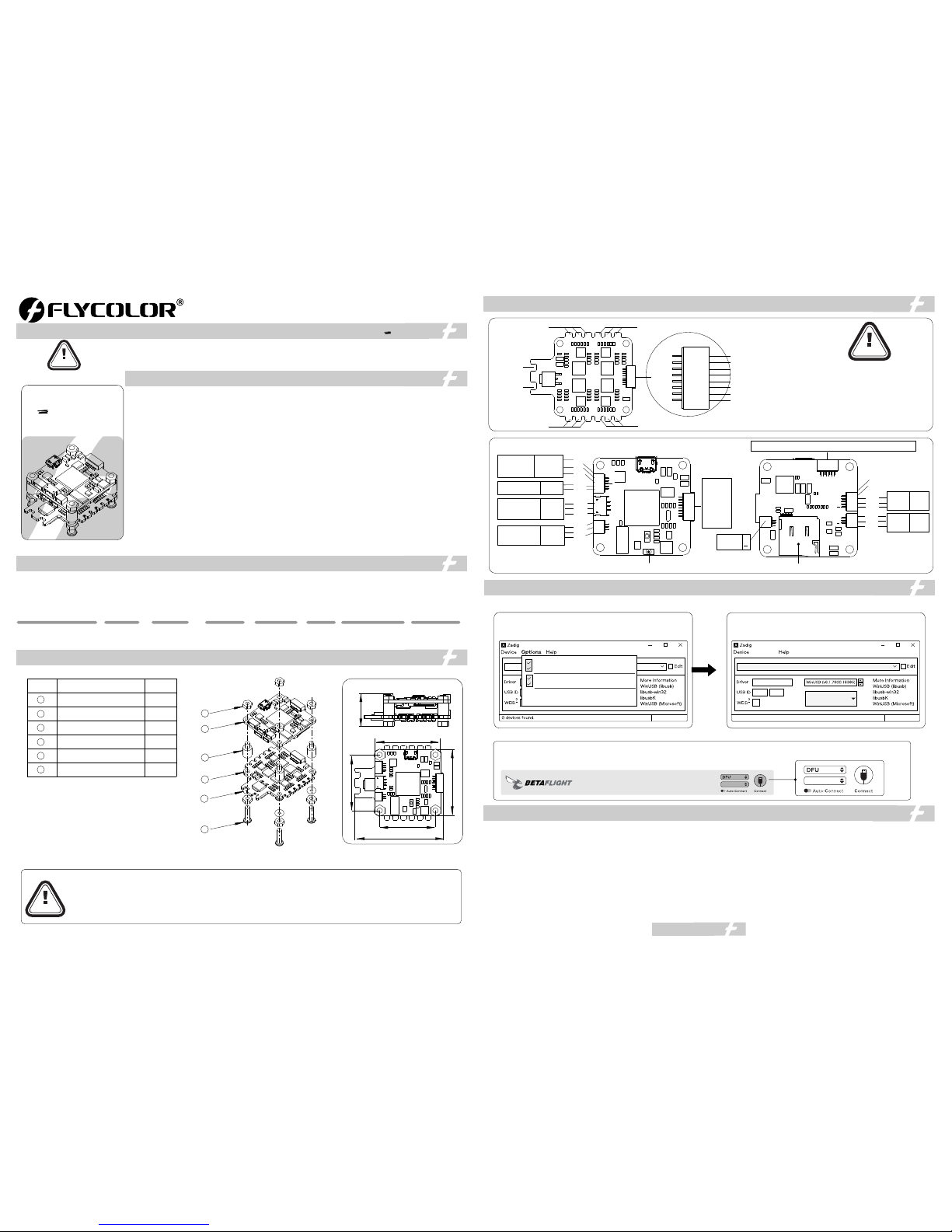
升级飞 控固件时, 长按BOO T按钮
T F卡槽
LE D
5V
GN D
LE D
LED
5V
GND
S5
S6
UART6-RX UART6-TX GND 5V UART3-TX UART3-RX
6
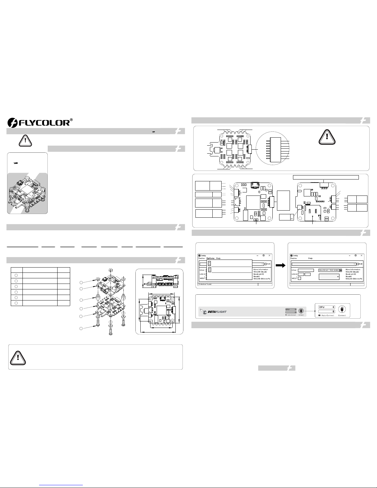
F4 飞控 需使用DFU模 式升级固件 。首次使用 需按照以下 步骤使用Za dig工具 替换驱动, 方能使用DF U模式。
6. 打开Be taflig ht;
7. 按住飞 控上的Boo t键,将飞控 USB与电 脑连接,此 时看到Bet afligh t更改为DF U模式连接 ,此时可以 进行固件刷 写;
8.可以通 过两种方式 刷固件:加 载本地固件 (推荐,需 在Betafi ght官网提 前下载)和 在线加载固 件;
1.运行Za dig 工具;
2.按住飞 控上的BO OT按键 不放,使用M icro U SB线将飞 控与电脑连 接;
3.点击Op tions ,选择List Al l Devic es;
4.在下拉 选项中选择 “STM 32 BO OTLO ADE R”,
再点击Re plac e Driv er;
5. 直到提 示成功,关 闭Zadig, 断开飞控U SB连接;
蜂鸣器
+
● 所有焊接 要求良好的 焊接技术, 任何时候都
需要避免 因焊接而造 成元件或线 材之间短路 ;
●为避免 短路和漏电 ,请确保连 接处绝缘良 好;
●接电之 前务必再次 检查极性是 否正确;
ATTENTION
电调
M3
电池 v -
3#电机
M1
M4
M2
4#电机
1#电机
2#电机
V-
V+
(注意: 如果您之前 运行过以上 步骤,之后 将不再需要 重复,直接 从第6步开始)
CONFIGURATOR 3.2.2
● 飞控固件请勿刷写除OMNIBUSF4SD 以外的固件,以免损坏飞控;
● PPM 接收机无需设置端口;
SBUS接收机 需手动将UART1的Serial RX打开;●
SPEKTR UM 接收机需手动将UART3的Serial RX打开;●
当使用LED灯带时,需在CLI 界面手动输入命令:●
输入:resource led_strip a8 然后回车;
输入:save 然后回车保存;
当检测到的电压和电流与实际有偏差时,可以调节Betaflight-Power&Battery●
中 电压计和电流计的Scale值;
● 只能用于低功率设备( 最大 , 最大 )。 5V 12V 5V 1A 12V 500mA
●首次 使用无刷电 调或更换遥 控设备后需 要进行油门 行程校准;
Dsho t 模式时, 将不再需 要校准油门 ;
● 使用B LHeli - 开源程序 ,32 请勿刷 写除Flyco lor_X _Cros s_BL _32以外
的固件,以 免损坏电调 ;
●无论 任何时候都 要注意极性 ,供电之前 一定要反复 检查;
●在插 拔或者做任 何连接时, 请关闭电源 ;
●可以 做一些减震 措施尽量避 免震动,因 加速度计/陀螺 仪对震动很 敏感;
●飞控 要远离一切 磁性材料;
●请不 要超出 工作电 流范围使用ES C ;
● 如需更 多信息,请 联系飞盈佳 乐售后或者 技术支持。
01主 要特 性
02 产 品规 格
03 元 件清 单/安装尺寸
04 电 调及 飞控连线示意图
05 飞 控固 件升级
06 注 意事 项
www. flyco lor.ne t
ATTENTION
● 对于快 速安装线束 ,连接前务 必确认您设 备接口的线 序与飞控接 口的线序是 对应关系。 如果您的图 传或摄像头 不适用配件 连接线的端
子,请 改装连接线 以适用于您 的设备。
● 请确保 所有电线和 连接部件绝 缘良好,避 免短路造成 产品损坏。
● 请保持 产品器件底 部与机架之 间有足够的 安全距离, 避免短路造 成产品损坏 ;
● 请避免 在潮湿、高 温等恶劣环 境下使用产 品,避免造 成产品损坏 。
Zadig 2.3. 701
List All Devic es
Ignore Hubs o r Composite P arents
Creat e a Catal og File
Sign Ca talog &Inst all Auto g enera ted cer tifica te
Advan ced Mod e
Log Verb osity
F11
Zadig 2.3. 701
STM32 BOOTL OADER
STTub30 (v3.0.4. 0)
0483
D
X
8 devices fou nd
Replace Dr iver
Option s
电池 v+
RX3
GND
3.3V
GND
12V
S
Camera
SBUS
PPM
5V
Tx1
Rx1
DSM
1#
GND
电池V+
2#
3#
4#
电流检测
电池V+
飞控
Video
S
12V
S5
S6
LED
5V
Buzzer
+
R
X
6
T
X
6
T
X
3
R
X
3
G
N
G
5
V
36 mm
36 mm
48.5 m m
30.5 m m
30.5 m m
18 mm
48. 5x41. 5x18m m
T0 wer
X
T0wer
X
26g
1#电调信 号线
GND
电池V+ 输出
2#电调信 号线
3#电调信 号线
4#电调信 号线
电流检测
GND
S1
S2
S3
S4
VBAT
ISA
VBAT
电池V+ 输出
ATTENTION
Dim ensio ns
Vide o
12V
GN D
12V
VT X.
S
12V
GND
S
GN D
3.3V
SP EKT RUM
Rec eiver
Rx3
GND
3.3V
12V
Cam era
GN D
12V
Vide o
SBUS/PP M
Receiver
SBUS/PPM
Vin
GND
5V
GND
SBUS
PPM
TX1
RX1
UA RT1
TX1
RX1
GND
12V
S
TF Ca rd
LE D
5V
GN D
LE D
str ip
LED
5V
GND
S5
S6
UART6-RX UART6-TX GND 5V UART3-TX UART3-RX
You nee d to use D FU mod e to reco ver firm ware fo r F4 Flig ht cont rolle r, and nee d a softw are too l calle d Zadig t o repla ce the dr iver fo r you F.C
when y ou flash fi rmwar e at the fir st time .
Zadig 2.3. 701
List All Devic es
Ignore Hubs o r Composite P arents
Creat e a Catal og File
Sign Ca talog &Inst all Auto g enera ted cer tifica te
Advan ced Mod e
Log Verb osity
6. Sta rt the “B etafli ght ” con figura tor on th e PC;
7. Pre ss and ho ld the “ BOOT ” on the F C, con nect th e FC to th e PC, th en the F C is con necte d in the “D FU” m ode, th en you ca n flash th e firmwa re;
8.Fo r the firm ware fla shing , you can c hoose t o load th e firmwa re onli ne or loc al(Loca l is reco mmend ed, it
need s to down load in a dvanc e in Beta flight w ebsit e)
1.St art the Z adig so ftwar e tool;
2.Pr ess and h old the “ BOO T” on th e FC, co nnect t he FC to t he PC .
3.Cl ick “Op tions ”,and s elect “ List All D evice s”.
4.Th en sele ct “ST M32 B OOT LOA DER” ,Then c lick “R eplac e Drive r”
5. Clo se the Za dig sof tware t ool whe n repla ce succ essfu lly,
Then d iscon nect th e FC fro m the PC .
BUZZER
+
(Noti ce:If you 've run t he abov e steps b efore , then yo u don't n eed to re peat, s tarti ng dire ctly fr om the 6t h step)
CONFIGURATOR 3.2.2
● Please don't flash any other firmware for FC except “OMNIBUS F4SD”.
● does not need to set the port.PPM receiver
SBUS receiver needs to turn on the “Serial RX” of UART1 port.●
SPEKTR UM ● receiver needs to turn on the “Serial RX” of UART3 port.
_Strip, please key in the following codes on the CLI:● When using LED
key in:“resource led_strip a8 ” ,then press the“Enter” on the keyboard.
key in:“save” ,then press the“Enter” on the keyboard.
is any deviation between the detected voltage/current with actual ●If there
situation, you can adjust the Scale value in the Betaflight-Power&Battery
● 5V ,12Vsupply is for low-current use only(5V 1A MAX, 12V 500mA MAX).
05 F la sh firmw ar e for FC
06 M or e infor ma tion
www. flyco lor.ne t
ATTENTION
Thank you for using our pro duct . A ny Impro per oper ation m ay cause person al injur y damag e to th e produc t and related equipmen ts. This high
power sy stem for RC model can be da ngerous ,w e strongly r ecommend re ading the us er manual ca refully an d completel y. We will not assu me any
respon sibility fo r any losses ca used by unau thorized mo dificatio ns to our produ ct. We have the ri ght to change t he design, ap pearance,
perfor mance and us age require ments of the p roduct wit hout notice .
ES C
● MC U:ST M32F 051 .,ARM 32-bi t Corte x MCU , frequ ency up t o 48 MHZ
● ES C firmwa re: .Flyc olor _X_Cr oss_B L_32
● Two lay ers tow er stru cture b etwee n 4in1 E SC and F C,us ing cab le for qu ick con necti on, usi ng vibr ation d ampin g
scre w for sup porti ng, red ucing t he effec t of vibr ation o n Fligh t Contr ol.
● Dam ped lig ht does r egene rativ e braki ng, cau sing ve ry fast m otor re tarda tion, a nd inhe rentl y also do es acti ve
free wheel ing.
● The co de sup ports re gula r 1-2ms p ulse wi dth inp ut, as we ll as One shot1 25 , Ones hot42 a nd Mult ishot .
● Dsh ot sign al is sup porte d at any ra te up to at le ast Dsh ot120 0.
Fli ght Con trol
● MC U:ST M32F 405.
● Gyro MPU -600 0 SPI .:
● FC fi rmwar e:Bet afligh t_OM NIB USF 4SD.
● Sup ports P PM, SBU S,SP EKT RUM 1024/ 2048 et c. remo te cont rol / rec eivin g mode.
● Sup ports ma x.32G T F-ca rd, whi ch can re cord an d save mo re fligh t/bla ck box da ta.
● FC i ntegr ated O SD, us ers can a djust O SD pa ramet ers via B etafli ght con figura tor.
● FC i ntegr ated 3. 3V,5V, 12V/ f or rece iver, V TX, ca mera, b uzzer, LED an d other p eriph eral de vices .
● Pro vided s evera l silic one cab les for F C ,and w ill giv e you an un prece dente d exper ience f or asse mbly.
● Inst all hol es:30 .5x30 .5mm, M3.
01 M ai n featu re s
02 S pe cifica ti ons
40A
45A
3-6 S
20g
3.3 V/5V/1 2V
Con. Curre nt
Bur st Curre nt
(10 S)
F.C Vout
Siz e
(For r efere nce)
Weig ht
LiP o cells
Typical Applications
(For reference)
Mod el
170 -450 Mu lti
03 P ar t list / Di me nsi on s
1
2
3
4
5
1
1
4
8
4
O-R ing
4
6
Des cript ion
Qty.
Ite m
32B it 4in1 E SC
F4 Fl ight Co ntrol ler
scr ew Vib ratio n dampi ng
M3+4 .5
Nyl on Nut M3
Nyl on scre w M3*12
1.Fo r quick p lug, Fl ight Co ntrol ler add ition ally pr ovide:
●One 5p c able (5 -pin S H1.0 t ermin al) for S BUS o r PPM r eceiv ers;
●One 3p c able (3 -pin Z H1.5 te rmina l)for SPE KTE UM rec eiver ;
●Thre e 3p cabl e (3-pi n SH1. 0 termi nal)f or diffe rent br and VT Xs;
●Two 3p ca bles (3 -pin S H1.0 te rmina l )for di fferen t brand C amera s;
●One 2p c ables (2-pi n SH1 .0 term inal) f or Buzz er;
●One 5p c ables (5-pi n SH1 .0 term inal) f or LED ,S5 an d S6;
●One 6p c ables (6-pi n SH1 .0 term inal) f or UAR T3 & UA RT6.
2.To enh ance pe rform ance of fi lteri ng, use rs can so lder th e elect rolyt ic
capa citor w hich ar e inclu ded in th e acces sory pa ck to the p ositi ve and
nega tive te rmina ls.
● For th ese qui ck plu g cable s, plea se confi rm the wi re sequ ences o n your de vices ’ connec tor are c orres pondi ng with t he Flig ht
cont rolle r’s be fore co nnect ing. If t he term inals a re not fit y our dev ices ,p lease m ake a mod ified co nnect ion to fit .
●The h eight f rom ES C to FC i s fixed , pl ease do n’t cha nge the h eight o f the nyl on spac er betw een the E SC& FC. it w ill cau se
the P CBs to d eform i f the hei ght too s hort. I t will ca use bad c onnec tion be tween t he ES C&FC if the he ight to o high.
● Ple ase ens ure all s older j oints & w ires ar e insul ated we ll, as sh ort cir cuit wi ll dama ge the pr oduct .
● Ple ase ens ure eno ugh saf ety spa ce betw een the E SC& Dr one fra mes, as s hort ci rcuit w ill dam age the p roduc t.
● Nev er use th is prod uct in ha rsh env ironm ents su ch as humi dity, hi gh temp eratu re, and s o on to avo id prod uct dam age
*All p ictur es are fo r refer ence on ly
ES C
F.C
Pres s the “B OOT ” for flas hing fir mware
● User needs to cal ibrate the thro ttle range when st arting to use a new E SC or
another tr ansmitter. Whe n the input signal is Ds hot, throttl e calibratio n is
disable d.
● BLHe li-32 firmware , please don't flas h any other firmwar e except
“Flycol or_X_Cros s_BL_32 ”.
● Observe pol arity at all times . Check and double ch eck before appl ying power.
● Power off befor e unplugging ,p lugging in or maki ng any connecti ons.
● Keep magnet s away from the Fligh t Controller .
● Do everythi ng you can to prevent vi brations.
● Please do not ex ceed the curren t range.
● Please cont act Flycolor sa les or technica l support for more in formation .
2514 00-10 91 V1.0
04 C on nect di ag ram of E SC and FC
User M anual
Mult i-Rotor B rushles s E S C
F11
Zadig 2.3. 701
STM32 BOOTL OADER
STTub30 (v3.0.4. 0)
0483
D
X
8 devices fou nd
Replace Dr iver
Option s
T0wer
X
T0 wer
X
X-Tow er F4-4 0A 48. 5x41. 5x18m m
1
2
3
4
5
6
36 mm
36 mm
48.5 m m
30.5 m m
30.5 m m
18 mm
M3
3# Mo tor
M1
M4
M2
4# Mo tor
1# Mo tor
2# Mo tor
V-
V+
GND
GND
S1
S2
S3
S4
VBAT
ISA
VBAT
Battery V -
Battery V+
1# sig nal
Batt ery V+ Ou tput
2# sig nal
3# sig nal
4# sig nal
Curr ent met er
Batt ery V+ Ou tput
ATTENTION
All so ldering t asks requ ire good s olderin g ●
techn ique,s hort circ uit betw een compo nents
or wire s should b e avoided a t any time .
Plea se ensure a ll solder j oints ar e insulat ed ●
with he at shrin k where nec essary.
●Plea se double -check th e polari ty is corre ct
befor e power up .
RX3
GND
3.3V
GND
12V
S
Camera
SBUS
PPM
5V
Tx1
Rx1
DSM
Video
S
12V
S5
S6
LED
5V
Buzzer
+
R
X
6
T
X
6
T
X
3
R
X
3
G
N
G
5
V
1#
GND
Batt ery V+
2#
3#
4#
Cur. me ter
Batt ery V+
 Loading...