

Flycolor X-Tower BL-32 4in1-40A User Manual

多旋翼飞行器
无刷电子调速器说明书
感谢您使 用本产品! 本产品功率 强大,错误 的使用可能 导致人身伤 害和设备损 坏,强烈建 议您在使用 设备前
仔细阅读 本说明书并 保存,严格 遵守规定的 操作程序。 我们不承担 因使用本产 品或擅自对 产品进行改 造所引
起的任何 责任,包括 但不限于对 附带损失或 间接损失的 赔偿责任。 我们有权在 不经通知的 情况下变更 产品的
设计、外 观、性能及 使用要求。
ATTENTION
01 主 要特性
X- To we r BL -3 2 4合1 ES C
持续电 流
瞬时电 流
(10 S)
BE C
尺寸(供参 考)
重量
锂电池 节数
型号
X-Tow er BL- 32 4in1 -40A
40A
45A
3-6 S
48. 5x40.8 x6mm
12.3 g
No
典型应 用(供参考)
170 -450多旋 翼
*图片仅供 参考,产品 以实物为准
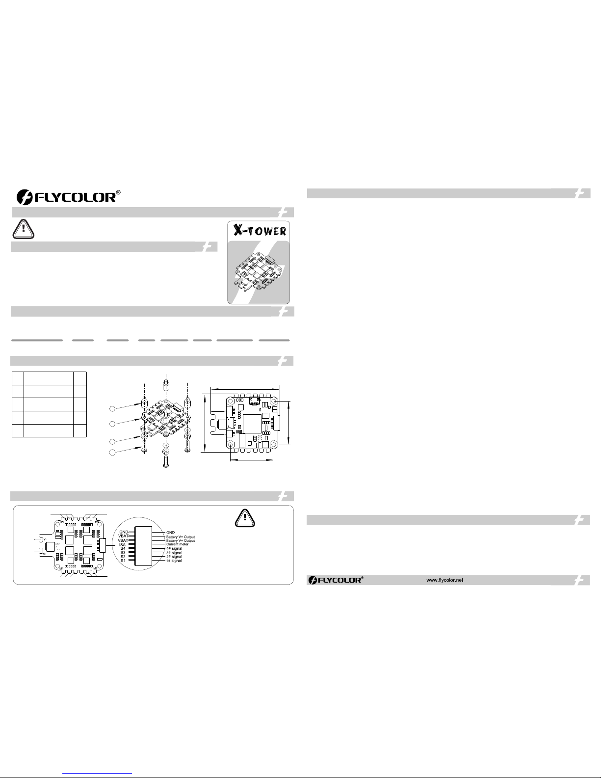
1.电调额 外提供了:
一根8Pi n线束(8P S H1.0端 子),用于 与飞控的连 接;
一根14 AWG电源 输入线束(X T60端子 )。
2.为加强 更好滤波效 果,用户可 选择使用配 件包中的电 解电容,焊 接在正负极 两端。
● 所有焊接 要求良好的 焊接技术, 任何时候都
需要避免 因焊接而造 成元件或线 材之间短路 ;
●为避免 短路和漏电 ,请确保连 接处绝缘良 好;
●接电之 前务必再次 检查极性是 否正确;
● VB AT 为电池电 压,如果连 接至其它设 备,
务必确认 设备的工作 电压是否匹 配;
●IS A为电流检测 口,可连接 至飞控对应 电流检测口 。
* 兼容市面 通用飞控, 推荐使用Fl ycolo r X-Tower F 4飞控。
安装尺 寸(mm)
X-Tow er BL- 32 4in1电 调
尼龙支 撑柱 M3*6+ 6
尼龙螺 母 M3
尼龙螺 钉 M3*10
序号
1
2
3
4
描述
数量
1
4
4
4
4
1
2
3
1. 启动功 率(Ramp up powe r):
启动功率 可以设置为 从3%-15 0%的相对值 。这是在启 动和提高转 速时允许最 大功率。对 于低转速, 为了便于低 反电动势电 压检测,最 大功率是被 限制的。
启动功率 也影响双向 操作,参数 是用来限制 在更改转向 时的功率。
在启动过 程中,实际 的功率取决 于油门输入 ,可低于设 定的最大启 动功率,但 最低是设定 的四分之一 。
2. 电机进 角(Moto r timin g):
电机进角 可以设置为1°- 31°,通常 设置中等数 值进角即适 用于大部分 电机,但如 果电机运转 不顺畅时,可以 尝试改变进 角。对于一 些高感电机 ,其换向退 磁时间较
长,尤其 在低速运转 的时候,电 机会在油门 快速增加的 情况下停转 或者不顺畅 。将进角改 高会有有助 于改善这个 现象,因为 高进角允许 更长的换向 退磁时间。
3.P WM频率 (PW M freq uency):
电机PW M频率可以设 置为16KH z-48K Hz。更高的P WM频率使电 机运行更顺 畅。频率可 设定也有可 能会导致油 门轻微移动 时造成大的 波动。
4 Dem ag补偿 (Dem ag comp ensat ion):.
Dema g 补偿是防止 电机由于换 向引起停转 的一个功能 ,典型的现 象是在快速 增加油门时 电机停转或 不顺畅,尤 其在低转速 运行时。如 前面所述, 设置高进角 可以帮助
改善, 但有可 能降低效率 。一般情况 下,Dema g补偿参数的 值越高,保 护越好。如 果补偿值设 置得太高, 最大功率将 有所降低。
5. 最大加 速度(Max imum Ac celer ation):
最大加速 度可以设置 在0.1% / ms -25.5 %/ ms之间, 也可以设置 为最大值, 在这种情况 下加速度不 受限制。限 制加速度的 主要目的是 避免在加速 不一致造成 失步的情
况。例如 :当设置为1 0% / ms时, 这意味着对电 动机施加的 功率不允许 每毫秒增加1 0%以上。
6 转向(Di recti on):
电机转向 可以设置为 正转/反转/双向正 转/双向反转。 在 双向模式下 ,油门中点 为零点,中 点以上为正 转,中点以下为 反转;当选 择双向操作 时,不可油 门校准。
7. 鸣叫 声强度 (Bee p stren gth):设 置正常运行 下鸣叫声强 度。
8.警报 音强度 (Bea con str ength ):
设置警报 音响起时的 强度。如果 油门信号在 零点位置的 时间超过一 个设定的时 间,电调将 开始报警。 请注意如果 设置一个高 的警报强度 将会导致电 机或电调发 热。
9.警报 音延迟 (Bea con del ay):设 置报警音开 始之前的延 时。
10.启 用油门校准(T hrott le Cal En able): 如果 禁用,将不 能油门校准 。
11. 最小 油门,最大 油门和中心 油门 (Min th rottl e, max th rottl e and cen ter thr ottle ):
设置电调 的油门范围 ;中点油门 只用于双向 操作;设置 值正常的为1 000us 到 2 000us的 输入信号。 对于其他输 入信号,该 值必须按比 例设置。
对于Dsh ot输入信号 ,这些设置 无效
12.温 度保护 (The rmal pr otect ion ):
可以启用 或禁用。温 度保护阀值 可以设置, 当温度高于 阀值时,电机功 率降低;当 温度高于阀 值15℃,电机功率 降低到25%; 电机功率不 会低于25%。
13.低 转速功率保 护 (Low RP M powe r prote ct):
低转速功 率限制可以 启用或禁用 。禁用它可 以以保证低 KV电机在 低电压运行时 实现全功率 。然而禁用 它将增加同 步丢失的风 险,伴随着 电机或ES C发热的可 能性。
14.低 压保护(Low Vo ltage P rotec tion):
低压保护 可以设置2. 5V/节-4. 0V/节锂电 池,或者可 以禁用。当 启用时,如 果电池电压 低于设定阈 值将限制电 机的功率。 此功能主要 用于固定翼 飞机。
15.停 车制动 (Bra ke on sto p):
可以启用 或禁用制动 。当设置启 用时,在通 电状态,油 门在零点位 置电机将会 有拖刹,阻 止电机转动 。如果油门 没有零点, 此项设置无 效。
16. LED控制 ( LED c ontro l):对于支 持的ESC, 可以控制发 光二极管(如果E SC支持)。
17.无 Da mped 模式 ( Non Dam ped Mod e):OFF - 有Dampe d 现象为刹车; ON- 无Dam ped 现象为 无刹车。
18.音 乐设置 (Mus ic Note C onfig): 可以设置个 性化音乐。
● AR M 32-bi t Corte x 核心MC U,工作频 率高达48M Hz;
● 四合一 集成电调, 快捷式排线 可连接飞控,安 装更快,更 方便;
● BL Heli- 32 固件,超 快响应速度 ,卓越的性 能;
● 四合一 电调内置电 流计;
● 电调上 电自动检测 油门信号, 支持普通PW M油门模 式(1-2ms) 的脉宽输入 、Onesh ot125(1 25-25 0us)、
Ones hot42 41.7 -83.3 us Mul tshot(5- 25us)( )和 ;
● 支持所 有Dshot 数字 信号,最高达到D shot1 200;
● Dam ped lig ht再生制动 ,使得效率 更高,油门 从大到小变 化时电机减 速响应更加 迅速,稳定 性和灵活性 显著加强 ;
● 支持更 高KV电机和 更大功率负 载,适合竞 速级多旋翼 的暴力飞行 ;
48.5mm
30.5mm
40.8mm
30.5mm
电调固 件:Flyco lor_X _Cros s_BL _32;
ATTENTION
M3
电池 v -
3#电机
M1
M4
M2
4#电机
1#电机
2#电机
V-
V+
电池 v+
1#电调信 号线
GND
电池V+ 输出
2#电调信 号线
3#电调信 号线
4#电调信 号线
电流检测
GND
S1
S2
S3
S4
VBAT
ISA
VBAT
电池V+ 输出
● 电调接 入飞行系统 后,每次上电会 自动检测输 入的油门信 号,然后执行相 应的油门模 式;
● 首次使 用无刷电调 或更换遥控 设备后需要 进行油门行 程校准 ;;Dsh ot 模式时, 将不再需 要校准油门
● 使用B LHeli -32 开源 程序,,请 勿刷写除Fly color _X_Cr oss_ BL_3 2以外的固件,以 免损坏电调 ;
● 无论任 何时候都要 注意极性, 供电之前一 定要反复检 查。
● 在插拔 或者做任何 连接时,请 关闭电源。
● 请不要 超出ESC工 作电流范围 使用。
● 可以做 一些减震措 施尽量避免 震动。
● 如需更 多信息,请 联系飞盈佳 乐售后或者 技术支持。
BL -3 2 4IN1
06 注 意事项
05 编 程参数值
04 电 调连线示意 图
03 元 件清单/安装尺 寸
02 产 品规格
ATTENTION
01 M ain f ea tur es
BE C
ATTENTION
06 A tte nt ion
* Comp atibl e with th e gener al FC. R ecomm end
the Fl ycolo r X-Towe r F4 Flig ht Cont rolle r.
Ins tall Di mensi ons(m m)
User Manua l
Multi-Ro to r Br us hless E S C
Thank yo u for using our product. An y Improper o peration may cause per sonal inju ry damage to the
produc t and rela ted e quipment s. Th is hi gh po wer s ystem for RC model can be d angerous ,we stron gly
recomm end readin g the user manu al careful ly and compl etely. We will no t assume any re sponsibi lity for any
losses ca used by unauthor ized modifica tions to our produ ct. We h ave the right to chang e t he d esign,
appear ance, perf ormance and u sage requi rements of t he product wi thout noti ce.
Con. Curr ent
Bur st Curre nt
(10 S)
Siz e
( For re feren ce )
Weig ht
LiP o cells
Typi cal Appl icati on
( For re feren ce )
Mod el
X-Tow er BL- 32 4in1 ESC
Nyl on spac er M3*6 +6
Nyl on Nut M3
Nyl on scre w M3*10
1
2
3
4
1
4
4
4
Ite m
Des cript ion
Qty.
1.E SC add ition al prov ide:
One 8- Pin cab le (8P S H1.0 te rmina ls) for c onnec tion
with F light C ontro ller;
One 14 AWG po wer inp ut cabl e(XT6 0 termi nal).
2.To enh ance pe rform ance of fi lteri ng, use rs can so lder th e elect rolyt ic
capa citor w hich ar e inclu ded in th e acces sory pa ck to the p ositi ve and
nega tive te rmina ls.
*All p ictur es are fo r refer ence on ly
● All weld ing requi res good we lding te chnolog y,
short c ircuit be tween th e element o r the wire
shoul d be avoide d at any tim e.
● Pleas e ensure al l solder j oints are i nsulate d
with he at shrink w here nec essary.
● Pleas e double- check th e polarit y is correc t
befor e power up.
● VBAT i s batter y output, m ake sure yo ur devic e
opera ting volt age is mat ched if you w ant to use
VBAT.
● ISA po rt can be co nnect to th e port on F.C
for cur rent mete r.
Firm ware :Flyco lor_X _Cros s_BL _32;
3#M otor
1#Mo tor
4#Mo tor
2#Mo tor
Batt ery v-
Batt ery v-
2514 00-10 97,V 1. 1
1. Ra mpup pow er:
Ramp up powe r can be se t to rela tive va lues fr om 3% to 15 0%. Thi s is the ma ximum p ower th at is all owed wh en ramp ing up at l ow rpms a nd duri ng star tup. Fo r
low rp ms, the m aximu m power t o the mot or is lim ited, i n order t o facil itate d etect ion of lo w BEM F volt ages.
Ramp up powe r also aff ects bi direc tiona l opera tion, a s the par amete r is used t o limit t he powe r appli ed duri ng dire ction r evers al.
Duri ng star tup, th e actua l appli ed powe r depen ds on thr ottle i nput, a nd can be l ower th an the ma ximum l evel se t by the ra mpup po wer par amete r, but the
mini mum lev el is a qua rter of t he maxi mum lev el.
2. Mot or timi ng:
Moto r timin g can be se t betwe en appr oxima tely 1° a nd appr oxima tely 31 ° in appr oxima tely 1° i ncrem ents (a ctual a ccura te valu es here a re 15/1 6ths of a d egree ).
Typic ally a me dium se tting w ill wor k fine, bu t if the mo tor stu tters i t can be be nefici al to inc rease t iming . Some mo tors wi th high i nduct ance ca n have a ve ry long
comm utati on dema gneti zatio n time. T his can r esult i n motor s top or st utter u pon qui ck thro ttle in creas e, part icula rly whe n runni ng at a low r pm. Set ting ti ming
to hig h will al low mor e time fo r demag netiz ation , and oft en help s.
3. PW M freq uency :
Moto r pwm fre quenc y can be pr ogram med bet ween 16 kHz and 4 8kHz. H igher p wm freq uency c an run mo tors sm oothe r. Progr ammab le freq uency a lso all ows for
movi ng of sma ll but po tenti ally di sturb ing hum ps in the t hrott le resp onse. Al l ESC s have th ese bum ps, wit h BLH eli_3 2 they ca n be move d in the rp m range , to a
plac e where t he syst em has lo w sensi tivit y to them .
4. De mag comp ensat ion:
Dema g compe nsati on is a fea ture to p rotec t from mo tor sta lls cau sed by lo ng wind ing dem agnet izati on time a fter co mmuta tion. T he typi cal sym ptom is m otor
stop o r stutt er upon q uick th rottl e incre ase, pa rticu larly w hen run ning at a l ow rpm. As m entio ned abo ve, set ting hi gh comm utati on timi ng norm ally he lps, bu t
at the c ost of effi cienc y. Gener ally, a hi gher va lue of th e compe nsati on para meter g ives be tter pr otect ion. If de mag com pensa tion i s set too hi gh, max imum po wer
can be s omewh at redu ced.
5. Max imum Ac celer ation :
Maxi mum acc elera tion ca n be set be tween 0 .1%/m s and 25. 5%/ms . It can al so be set t o maxim um, in wh ich cas e accel erati on is not l imite d. Limi ting ac celer ation
is pri maril y inten ded as a ba ckup pa ramet er that c an be use d in case s where t oo hard a ccele ratio n gives d esync s. When s ettin g to e.g. 1 0%/ms , it mean s that th e
powe r appli ed to the m otor is n ot allo wed to in creas e by more t han 10% p er mill iseco nd.
6. Dir ectio n:
Rota tion di recti on can be s et to fwd /rev/ bidir ectio nal fwd /bidi recti onal re v. In bidi recti onal mo de, cen ter thr ottle i s zero an d above i s fwd rot ation a nd belo w is
reve rse rot ation . When bi direc tiona l opera tion is s elect ed, thr ottle c alibr ation i s disab led.
7. Be ep stren gth: Se ts the st rengt h of beep s under n ormal o perat ion.
8. Be acon str ength :
Sets t he stre ngth of b eeps wh en beep ing bea con bee ps. The E SC wi ll star t beepi ng beac on beep s if the th rottl e signa l has bee n zero fo r a given time. N ote tha t
sett ing a hig h beaco n stren gth can c ause ho t motor s or ES Cs!
9. Be acon del ay: Bea con del ay sets t he dela y befor e beaco n beepi ng star ts.
10.T hrott le Cal En able: I f disab led, th rottl e calib ratio n is disa bled.
11. Mi n thrott le, max t hrott le and ce nter th rottl e:
Thes e setti ngs set t he thro ttle ra nge of th e ESC . Cente r throt tle is on ly used f or bidi recti onal op erati on. The va lues gi ven for t hese se tting s are for a n ormal
1000 us to 200 0us inp ut sign al, and f or the ot her inp ut sign als, th e value s must be s caled . For Dsh ot inpu t signa l, thes e setti ngs hav e no effec t.
12.T herma l prote ction :
Ther mal pro tecti on can be e nable d or disa bled. An d the tem perat ure thr eshol d can be pr ogram med The p rogra mmabl e thres hold is p rimar ily mea nt as a sup port
for ha rdwar e manuf actur ers to us e, as diff erent h ardwa res can h ave diff erent t olera nces on t he max te mpera tures o f the var ious co mpone nts use d.
13.L ow RP M power p rotec t:
Powe r limit ing for l ow RP Ms can be e nable d or disa bled. D isabl ing it ca n be nece ssary i n order t o achie ve full p ower on s ome low k V motor s runni ng on a low
supp ly volt age. Ho wever, d isabl ing it in creas es the ri sk of syn c loss, w ith the p ossib ility o f toast ing mot or or ES C.
14.L ow Volta ge Prot ectio n:
Low vo ltage p rotec tion ca n be set be tween 2 .5V and 4 .0V per l ipo cel l. Or it ca n be disa bled. W hen ena bled, i t will li mit pow er appl ied to th e motor i f the bat tery
volt age dro ps belo w the pro gramm ed thre shold . This fe ature i s prima rily in tende d for fixe d wing cr afts.
15.B rake o n stop:
Brak e on stop c an be set b etwee n 1% and 10 0%, or di sable d. When n ot disa bled, b rake wi ll be app lied wh en thro ttle is z ero. Fo r nonze ro thro ttle, t his set ting
has no e ffect.
16. LED Co ntrol : LED s can be co ntrol led on E SCs th at supp ort it.
17. Non Damp ed Mode:O FF- Da mped li ght is ava ilabl e ; ON- No D amped l ight。
18. Music No te Confi g: Set up pe rsona lized m usic.
Pro gramm ing par amete rs belo w can be ac cesse d from th e config urati on soft ware (B LHe liSui te32) :
4
1
2
3
48.5mm
30.5mm
40.8mm
30.5mm
● .ARM 32-bi t Corte x MCU , frequ ency up t o 48 MHZ
● 4in 1 ESC us ing cab le for qu ick con necti on mak es the in stall ation fa ster an d more co nven ient.
BLH eli_ 32 firmw are,whi ch is des igned f or supe rior fu nctio nalit y and per forma nce.●
● 4in 1 ESC bu ilt-i n curre nt sens or.
● Sup ports r egula r 1-2ms p ulse wi dth inp ut, as we ll as One shot1 25 (125 -250u s), One shot4 2 (41.7 -83.3 us) and
Mult shot (5 - 25us) . The inp ut sign al is aut omati cally d etect ed by the E SC up on powe r up.
● Dsh ot sign al is sup porte d at any ra te up to at l east Dsh ot120 0.
● Dam ped lig ht does r egene rativ e braki ng, cau sing ve ry fast m otor re tarda tion, a nd inhe rentl y also do es acti ve
free wheel ing.
● Sup ports h igher K V moto r and mor e power l oad, mo re suit able fo r viole nt fligh t of raci ng dron e .
BL -3 2 4IN1
X- To we r BL -3 2 4i n1 E SC
X-Tow er BL- 32 4in1 -40A
40A
45A
3-6 S
48.5 x40.8 x6mm
12. 3g
No
170 -450 Mu lti
● ES C will au tomati cally d etect t he input t hrott le sign als ever y time as s oon as it po wered o n, and th en execu te the co rrespo nding s ignal -rece iving
mode .
● User n eed to ca librat e the thr ottle r ange whe n start ing to use a n ew ES C or anot her tran smitt er. When th e input s ignal i s Dshot, t hrott le cali bratio n
is dis abled .
● BL Heli- 32 firmw are, ple ase don 't flash an y other fi rmwar e except “ Flyco lor_X _Cross _BL_ 32”.
● Obse rve pol arity at a ll time s. Chec k and doub le chec k befor e applyi ng powe r.
● Powe r off befo re unplu gging , pluggi ng in or ma king an y connec tions .
● Plea se do not e xceed t he curre nt rang e.
● Do eve rythi ng you can t o preve nt vibr ations .
● Plea se cont act Flyc olor sa les or te chnica l suppo rt for mo re infor matio n.
05 E SC Pr ogr ammin g param ete r
04 W iri ng d iag ram of E SC
03 P art l is t / Ins tall Di men si ons
02 S pec ifi cat ion
 Loading...