

Flycolor Raptor S-Tower-30A, Raptor S-Tower-20A, W4-FW020004-SX, W4-FW030004-SX User Manual

ATTENTION
01 Main f eatur es
02 Spec ificat ions
03 Part l ist / Ins tall Di mensions
Raptor S-Tower
W4- FW0 200 04 -S X
Rap tor S-Tow er-20 A
20A 30A
2- 4S
41. 5x36x 19.6m m
20g
No
130 -330 Mu lti
W4- FW0 300 04 -S X
Rap tor S-Tow er-30 A
30A 40 A
2- 4S
41. 5x36x 19.6m m
20g
No
170 -450 Mu lti
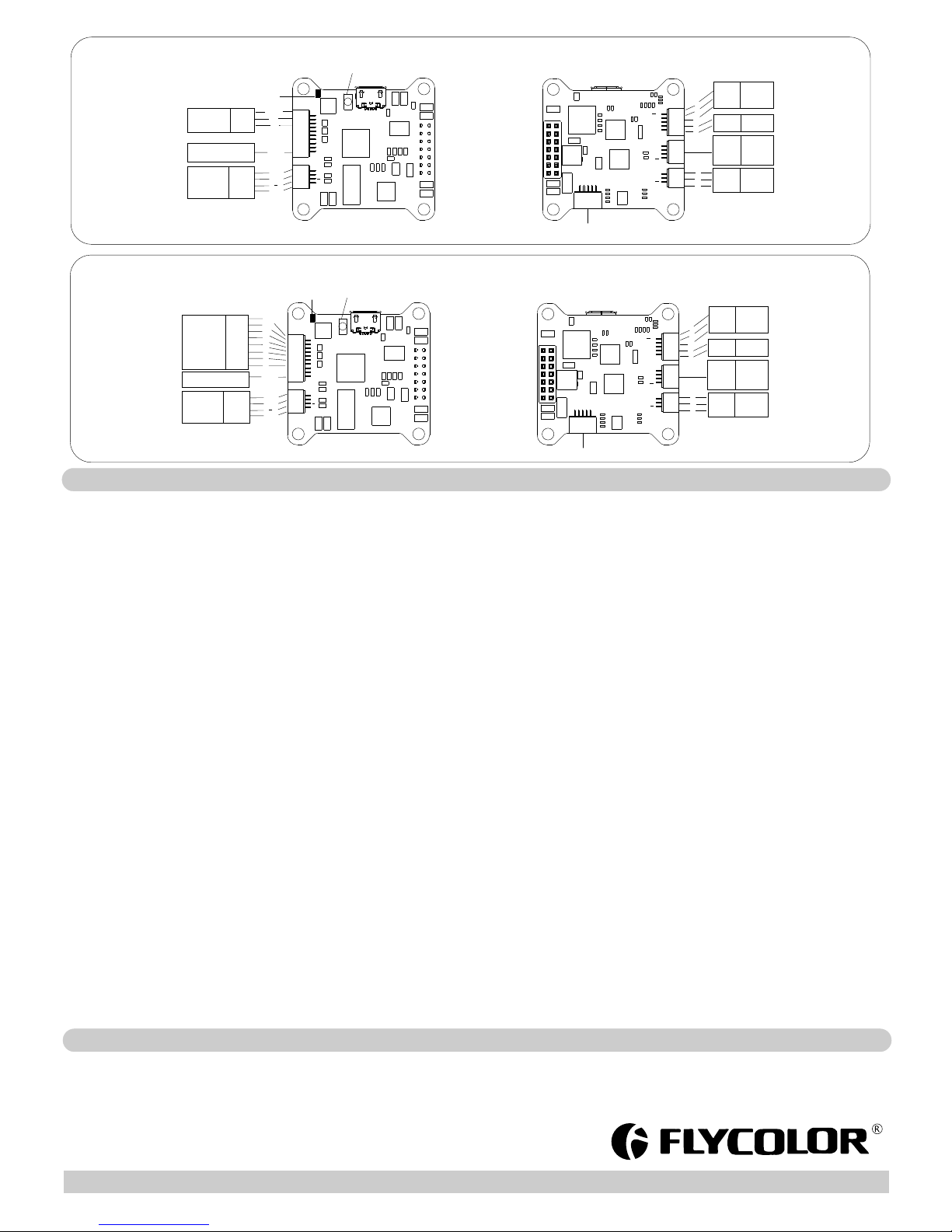
04 Wiri ng diag ram of E S C and FC re ceivi ng mode
ATTENTION
Inst all Dim ensions
19. 6 mm
36 mm
36 mm
41. 5 mm
30. 5 mm
30. 5 mm
1
2
3
4
*Ra ptor S- Towe r is usin g the A-H- 15 BL He li- S firmwa re; Ple ase con tact Fl ycolo r for mor e infor matio n.
*图片仅供 参考,产品以 实物为准
RAPTOR
TO WE R
S
ESC
M3
Bat tery V -
Bat tery v+
3#M otor
M1
M4
M2
4#M otor
1#M otor
2#M otor
V-
V+
Dua l ways si gnal
tra nsmis sion
Than k you for p urchasin g our pro duct . Any Impro per operat ion may c ause perso nal injury d amage t o the produc t and rel ated equip ments. This h igh power
syst em for RC mo del can be d anger ous ,we str ongly recom mend read ing th e user m anual car efull y and c omple tely. We w ill no t assu me any respo nsib ility
for any losses cau sed by unautho rized mod ificat ions to o ur pr oduct. We have the right to change the design , appearan ce, perfo rmance and usage
requ ireme nts of the pro duct wi thout noti ce.
● EF M8B B21F1 6G MC U, pipe lined 8 -bit C8 051 cor e with 50 MH z max imum op erati ng freq uency.
ES C maxi mum spe ed is lim ited to 5 00k eR PM.● Ded icate d high fr equen cy driv er, mak es the st art mor e smoot h.
Dua l ways si gnal tr ansmi ssion● Two la yers to wer s truct ure bet ween 4i n1 ES C and FC u sing qu ick pin c onnec tion. mak es the fli ght mor e stabl e
● Exp osed pa ds for Ba ttery a nd Moto r wires , fast we lding w ithou t addit ional d isass embly, m ake s the ins talla tion fa ster an d more co nveni ent.
.● F3 fli ght con troll er, supp orts P PM, P WM and S BUS r emote c ontro l / recei ving mo de
● FC i ntegr ated O SD, al so inte grate d 5V/1A , 12V/5 00mA for I mage tr ansmi tter, ca mera, b uzzer, LE D and ot her p eri phera l devic es ; prov ided
sev eral si licon e cable s for con necto rs on FC , and wil l give yo u an unpr ecede nted ex perie nce for i nstal latio n;
● Con nect co mpute r via US B on the fl ight co ntrol ler, the n can upg rade E SC sof tware d irect ly or adj usted t he ES C set tings d irect ly ;
Bui lt-in c urren t meter, ● OS D dire ctly di splay t he real -time c urren t witho ut any ad ditio nal con necti on;
BL Heli -S firmw are is th e next ge nerat ion cod e, foll owing t he base B LHe li code . It desi gned fo r super ior per forma nce in mu ltiro tors, a nd uses h ardwa re ●
gen erate d motor p wm for sm ooth th rottl e respo nse and s ilent o perat ion.
Sup ports f eatur es to pre vent sy nc loss . Th ere are t uneab le para meter s that ca n make th e code ru n well ev en in the m ost dem andin g situa tions , altho ugh def ault ●
set tings w ill wor k excel lentl y in norm al oper ating e nviro nment s.
The c ode sup ports r egula r 1-2ms p ulse wi dth inp ut, as we ll as One shot1 25 , Ones hot42 a nd Mult ishot . T he in put sig nal is au tomat icall y detec ted by th e ESC u pon ●
pow er up.
● Sup ports D shot1 50, Dsh ot300 a nd Dsho t600. Dshot i s digit al sign al, ant i-int erfer ence ab ility i s stron ger, and d o not nee d throt tle cal ibrat ion.
Con. Cur rent
Bur st Curr ent
(10 S)
BE C
Siz e
(Fo r refer ence)
Wei gh t
LiP o cells
Manufacture Model
Typi cal App licat ions
(Fo r refer ence)
Mod el
Rap tor BL S 4in1 ES C
Fli ght Con troll er
Nyl on Nut M3
Nyl on spac er M3*6 +6
Nyl on scre w M3*10
(No t shown i n figure )
1
2
3
4
5
1
1
8
8
4
Ite m
Des cript ion
Qty.
For q uick pl ug, Fli ght Con troll er addi tiona lly pro vide:
one 1 0p cabl e (10-p in SH1 .0 term inal) f or PW M or PP M conne ctors ;
one 3 p cable ( 4-pin S H1.0 t ermin al)fo r SBU S conn ector ;
one 5 p cable ( 5-pin S H1.0 t ermin al)fo r LED a nd Buzz er.
thr ee 4p cab les(4 -pin S H1.0 ) fo r differ ent bra nd Imag e Trans mitte rs.
two 3 p cable s (3-pi n SH1. 0 )for di fferen t brand C amera s;
Att entio n: For th ese qui ck plug c ables , pleas e confir m the wir e
seq uence s on your d evice s’ conne ctor ar e corre spond ing wit h the
Fli ght con troll er’s be fore co nnect ing. If t he term inals a re not fit y our
dev ices ,p lease m ake a mod ified co nnect ion to fit .
All w eldi ng re qui res go od we ldi ng te chno log y, shor t cir cuit b etw een t he ele men t ●
or th e wire s hou ld be a void ed at a ny ti me.
Ple ase en sur e all s olde r joi nts a re in sula ted w ith h eat sh rin k whe re nec ess ary.●
●Ple ase do ubl e-c heck t he po lar ity i s corr ect b efo re pow er up .
*Al l pictu res are f or refe rence o nly
12V
Cam era
S
12V
GN D
3
2
1
IS P progr ammin g (OS D Debug )
5V
LED
5V
Buz-
RX
TX
5V
LE D
GN D
5V
LE D
Buz zer
5V
Buz zer
SB US
Rec eiver
RX
5V
GN D
1
2
4
1
2
3
4
5
S
12V
Camer a
SBU S
ISP
T
X
R
X
D
T
R
5
V
G
N
D
BOT TO M
SB US Mode
TO P
GND
5V
1
2
3
4
5
6
AD1
AD2
GND
12V
S
S.Por t
BOO T
AD2
RS SI
Video
PPM/PWM
Pre ss “BO OT” f or re cover ing firm ware
Sma rt Port P ad
GND
Vin
GND
VIDEO
GND
12V
S
Ima ge
tra nsmit ter
User Manual
Multi-Rotor Brushless ES C
05 ESC Progr ammin g param eter
ww w.fl yco lor.ne t
251 400-1 062,V 1 .0
06 Atte ntion
TO P
GND
5V
1
2
3
4
5
6
AD1
AD2
GND
12V
S
S.Por t
BOO T
AD2
RS SI
Video
PPM/PWM
Pre ss “BO OT” f or re cover ing firm ware
Sma rt Port P ad
GND
Vin
GND
VIDEO
GND
12V
S
Ima ge
tra nsmit ter
GN D
5V
CH 1
PP M
Rec eiver
GN D
5V
1
12V
Cam era
S
12V
GN D
3
2
1
IS P progr ammin g (OS D Debug )
5V
LED
5V
Buz-
RX
TX
5V
LE D
GN D
5V
LE D
Buz zer
5V
Buz zer
1
2
3
4
5
S
12V
Camer a
SBU S
ISP
T
X
R
X
D
T
R
5
V
G
N
D
BOT TO M
UA RT3
RX
TX
5V
GN D
12V
Cam era
S
12V
GN D
3
2
1
IS P progr ammin g (OS D Debug )
5V
LED
5V
Buz-
RX
TX
5V
LE D
GN D
5V
LE D
Buz zer
5V
Buz zer
1
2
3
4
5
S
12V
Camer a
SBU S
ISP
T
X
R
X
D
T
R
5
V
G
N
D
BOT TO M
UA RT3
RX
TX
5V
GN D
TO P
GND
5V
1
2
3
4
5
6
AD1
AD2
GND
12V
S
S.Por t
BOO T
Video
PPM/PWM
Pre ss “BO OT” f or re cover ing firm ware
Sma rt Port P ad
GND
Vin
GND
VIDEO
GND
12V
S
Ima ge
tra nsmit ter
PW M
Rec eiver
GN D
5V
CH 1
CH 2
CH 3
CH 4
CH 5
CH 6
GND
5V
1
2
3
4
5
6
AD2
RS SI
PPM Mode
PWM Mode
1. St artup p ower:
Sta rtup po wer can b e set to re lativ e value s from 0. 031 to 1. 5. This i s th e max im um po we r tha t is a llo we d dur in g sta rt up. Ac tual ap plied p ower de pends o n throt tle inp ut, and
can b e lower, b ut the mi nimum l evel is a q uarte r of the ma ximum l evel. S tartu p power a lso affe cts bid irect ional o perat ion, as t he para meter i s used to l imit th e power a pplie d
dur ing dir ectio n rever sal. Fo r low rpm s, the ma ximum p ower to t he moto r is limi ted, in o rder to f acili tate de tecti on of low BE MF vol tages . Th e ma xim um p owe r al low ed c an be
set v ia the st artup p ower pa ramet er.
2. Co mmuta tion ti ming:
Com mutat ion tim ing can b e set to lo w/med iumlo w/med ium/m edium high/ high, t hat cor respo nd to 0°/7. 5°/15°/22 .5°/30° ti ming ad vance .
Typi cally a m edium s ettin g will wo rk fine, b ut if the m otor st utter s it can be b enefic ial to ch ange ti ming. S ome mot ors wit h high in ducta nce can h ave a ver y long co mmuta tion
dem agnet izati on time . Th is c an re su lt in m ot or st op o r stu tt er up on q uic k th rot tl e inc rease , parti cular ly when r unnin g at a low rp m. Sett in g tim ing to hi gh will a llow mo re time f or
dem agnet izati on, and o ften he lps.
3. De mag com pensa tion:
Dem ag comp ensat ion is a fe ature t o prote ct from m otor st alls ca used by l ong win ding de magne tizat ion tim e after c ommut ation . Th e ty pic al s ymp to m is mo to r sto p or s tut te r
upo n quick t hrott le incr ease, p artic ularl y when ru nning a t a low rpm . As me ntion ed abov e, sett ing hig h commu tatio n timin g norma lly hel ps, but a t the cos t of effici ency.
Gen erall y, a hi gh er va lu e of th e co mpe ns ati on p ara me ter g iv es be tter pr ot ect ion. If d emag co mpens ation i s set too h igh, ma ximum p ower ca n be some what re duced .
4. Di recti on:
Rot ation d irect ion can b e set to fw d/rev /bidi recti onal fw d/bid irect ional r ev. In bid ir ect io nal m od e, ce nt er th ro ttl e is z ero a nd a bov e is f wd ro tatio n and bel ow is rev erse ro tatio n.
Whe n bidir ectio nal ope ratio n is sele cted, p rogra mming b y TX is di sable d.
5. Be ep stre ngth:
Set s the str ength o f beeps u nder no rmal op erati on.
6. Be acon st rengt h:
Set s the str ength o f beeps w hen bee ping be acon be eps. Th e E SC w ill s tart be eping b eacon b eeps i f the t hr ott le s ign al h as be en z ero f or a g ive n ti me. N ot e tha t setti ng a h igh
bea con str ength c an caus e hot mot ors or E SCs!
7. Be acon de lay:
Bea con del ay sets t he dela y befor e beaco n beepi ng star ts.
8. Pr ogram ming by TX : If d isa bl ed, t hr ott le c ali brati on is dis abled .
Ple ase not ice tha t throt tle sti ck can ca libra te thro ttle ra nge onl y, an d ca n not p ro gra mm ing p ar ame nt er vi a th rot tl e sti ck .
9. Mi n throt tle, ma x throt tle and c enter t hrott le:
The se s ett in gs se t th e thr ot tle r an ge of t he E SC. C ent er t hro tt le is o nl y use d fo r bid ir ect ional o perat ion. Th e val ues giv en for th ese set tings a re for a no rmal 10 00us to 2 000us
inp ut sign al, and f or the ot her inp ut sign als, th e value s must be s caled .
10. Therm al prot ectio n:
The rm al pr ot ect io n can b e en abl ed o r dis ab led . And t he t emp eratu re thre shold c an be pro gramm ed betw een 80°C an d 140°C(fro m rev16 .3).
The E SC me asu res tem perat ure wit hin the MC U and li mit s motor p ower if t he temp eratu re is too h igh. Mo tor pow er is lim ited in f our ste ps:
- If th e tempe ratur e is abov e thres hold , mo tor pow er is lim ited to 7 5%.
- If th e tempe ratur e is abov e thres hold 5°C, m otor po wer is li mited t o 50%.
- If th e tempe ratur e is abov e thres hold 10°C , motor p ower is l imite d to 25%.
- If th e tempe ratur e is abov e thres hold 15°C , motor p ower is l imite d to 0%.
11.L ow RP M po wer p rotec t:
Pow er limi ting fo r low RP Ms can b e enabl ed or dis abled . Disab ling it c an be nec essar y in orde r to achi eve ful l power o n some lo w kV moto rs runn ing on a lo w suppl y volta ge.
How ever, di sabli ng it inc rease s the ris k of sync l oss, wi th the po ssibi lity of t oasti ng moto r or ES C.
12. Brake o n stop:
Bra ke on sto p can be en abled o r disab led. Wh en enab led, br ake wil l be appl ied whe n throt tle is ze ro. For n onzer o throt tle, th is sett ing has n o effect .
Program mi ng p ar am eters below c an b e ac ce ss ed from the c on fig ur at io n softwar e (BL H el iSuite) :
● Use r need to c alibr ate the t hrott le rang e when st artin g to use a ne w ESC o r anoth er tran sm itt er. When t he inpu t signa l is Dsho t, thro ttle ca libra tion is d isabl ed
● BL Heli -S open -sour ce firmw are, wh en some a bnorm ality o ccurs i n ESC d ri vin g th e mot or o r nee d the mot or to rea ch a high er RP M, u ser c an t ry to c ha nge t he t imi ng.
● Obs erve po larit y at all ti mes. Ch eck and d ouble c heck be fore ap plyin g power . ● Power o ff befor e unplu gging , pl ugg ing in or m aking a ny conn ectio ns.
● 5V ,1 2Vsup ply is fo r low-c urren t use onl y(5V 1A M AX, 12 V 500mA M AX ). ● Kee p mag ne ts aw ay f rom t he F lig ht C ont ro lle r.
● Do ev eryth ing you c an to pre vent vi brati ons. ● Pl ea se co nt act F ly col or s ale s or tech nical s uppor t for mor e infor matio n.
User Manual
Multi-Rotor Brushless ES C
 Loading...