

Flycolor Raptor390 4in1-20A, Raptor390 4in1-30A User Manual
多旋翼飞行器
无刷电子调速器说明书
感谢您购 买本产品! 本产品功率 强大,错误 的使用可能 导致人身伤 害和设备损 坏,强烈建 议您在使用 设备前
仔细阅读 本说明书并 保存,严格 遵守规定的 操作程序。 我们不承担 因使用本产 品或擅自对 产品进行改 造所引
起的任何 责任,包括 但不限于对 附带损失或 间接损失的 赔偿责任。 我们有权在 不经通知的 情况下变更 产品的
设计、外 观、性能及 使用要求。
ATTENTION
● 电调采 用功能强大C 8051F 390 MC U,8位C805 1核心 ;,工作 频率高达50 MHz
安装更 快,更方便 ;专用的三 合一驱动IC ,反应更快 支持 万转速 ;● 四合一 集成电调, ;电调 最高 40
● ; 只需使 用极短信号 线连接飞控 ,最大程度 降低信号传 输所产生的 干扰,使飞 行更稳定
● 使用 开源程 序;默认 模式, 效率更高, 显著提升油 门响应速度 。油门从大 到小变化时 ,BL Heli Dam ped lig ht
电机减 速响应更加 迅速,多旋 翼稳定性和 灵活性得到 显著加强, 特别适合穿 越机使用;
● 多种参 数可设置, 使得电调能 够在最暴力 的配置下运 行,即使默 认设置也能 在正常配置 下出色的运 行;
电调上 电自动检测 油门信号, 支持普通油 门模式1-2m s的脉宽输 入,onesh ot125 (125- 250us ),●
one shot4 2(41. 7-83. 3us)和 mu ltish ot(5- 25us)。
01 主 要特性
02 产 品规格
03 元 件清单/安装尺 寸
Raptor39 0 4合1 ES C
持续电 流
瞬时电 流
(10 S)
BE C
尺寸(供参 考)
重量
锂电池 节数
型号
Rap tor39 0 4in1- 20A
20A 30A
2-4 S
41.5 x36x 5mm
9.5 g
No
典型应 用(供参考)
130 -330多旋 翼
Rap tor39 0 4in1- 30A
30A 40A
2-4 S
41. 5x36x 5mm
9.5 g
No
170 -450多旋 翼
*图片仅供 参考,产品 以实物为准
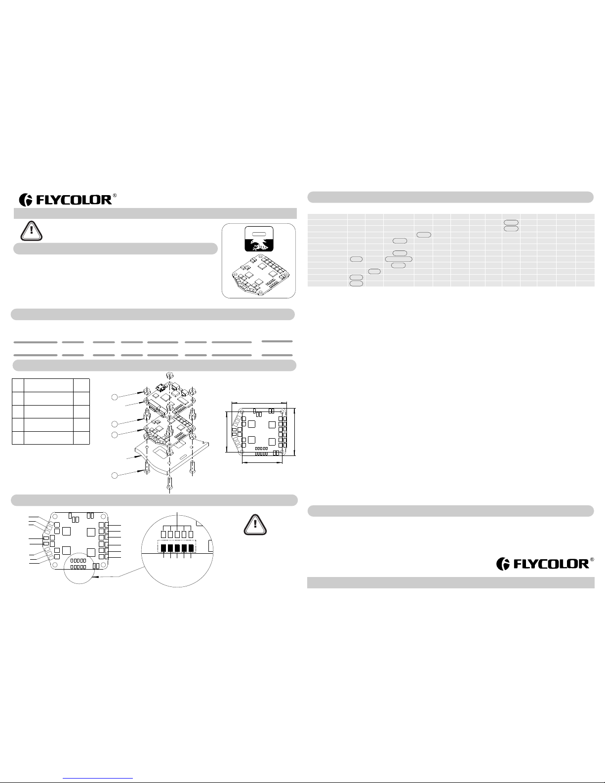
04 电 调连线示意 图
电调额外 提供了:
一根5Pi n线束(5个JR 端子),用 于与飞控的 连接;
一根14 AWG电源 输入线束(X T60端子 )。
● 所有焊接 要求良好的 焊接技术, 任何时候都
需要避免 因焊接而造 成元件或线 材之间短路 ;
●为避免 短路和漏电 ,请确保连 接处绝缘良 好;
●接电之 前务必再次 检查极性是 否正确;
ATTENTION
05 编 程参数值
表中圈 出标识为默 认值
* 从 . 开始,默认 值为 支持此 功能的电调 较早版 本默认值仍 然为“高” 。BL Heli 14 4 Dam ped lig ht( );
**默认 的启动功率 是根据ES C变化的。 一般情况下 大的ESC默 认启动功率 比较低。
*** . 以及之前 的版本,选 项为: / BL Heli 14 4 7/1 5 3 1/63
1. 转速 闭环比例增 益(Close d loop P ga in):通过 比例增益来 控制电机。
2. 转速 闭环积分增 益(Close d loop I ga in):通过 积分增益来 控制电机。
3. 转速 闭环模式(C losed l oop mod e):设定控 制回路工作 的速度范围 ,以一对极 电机为例:
-高:油 门值从0%到100 %,转速从0到2 00,00 0 RPM ;
-中:油 门值从0%到100 %,转速从0到1 00,00 0 RPM ;
-低:油 门值从0%到100 %,转速从0到5 0,000 R PM;
-关:当 闭环模式设 置为关闭时 ,转速闭环 被禁用。
4. 多轴 增益(Mult i gain): 该功能把P WM输入信 号按照比例 给电机提供 能量(PP M输入信号 无效)。注意低 增益会限制 电机的最大 功率。
5. 启动 功率(Star tup pow er):启 动时总是用 直接启动的 方法,它使 用每次启动 时检测的反 电动势来运 行电机。在 这种模式下 ,功率是由 使用的油门 提供的,
但限制 在一个最大 的值。这个 最大值由启 动功率参数 来控制。
要注意 的是,设置 启动功率太 高会造成 ES C或电机 过载!
6. 进角( Commut ation t iming ): 低进角 约0°、中低进 角8°、中进角15° 、中高进角2 3°、高进 角30°。通常 设置中进角 适用于大部 分电机,但 如果电机运 转不顺
畅时,可以 尝试改变进 角。
7. PW M 频率(P WM fre quenc y):
-高:高P WM频率 在20kHz; -低: 低PWM频 率在8kHz;
-Da mped li ght: (现 象为刹车) 该功能可以 加快电机的 减速,该模式使 用的是高PW M频率。 只有一些Mos fet开关 足够快的ES C支持Dam ped lig ht模式。
8. PW M加速控 制(Pwm dit her):此 功能控制P WM加速时 每次的加速 值。这种方 法能使电机 的加速变得 流畅。特别 适合于Dam ped lig ht 模式下时 使用。PW M
加速控 制不适用于 转速闭环模 式。
9. Dem ag补偿(D emag co mpens ation ):Demag补 偿是防止电 机由于换向 引起停转的 一个功能, 典型的现象 是在快速增 加油门时电 机停转或卡 顿,尤其在 低
转速运 行时。如前 面所述,设 置高进角可 以帮助改善,但 有
可能降 低效率。一 般情况下,D emag补偿 参数的值越 高,保护越 好。如果补 偿值设置得 太高,最大 功率将有所 降低。
10. 转 向(Rotat ion dir ectio n):可用于 设置电机反 向旋转。
11. 输入P WM极性(I nput pw m polar ity):能 够适用于反 极性的PW M输入情况 。当使用P PM的输入 时必须设置 为正。
以下参 数只能从B LHeli地 面站编程( BLHe lisui te):
PP M输入油门的 最小值和最 大值 (PP M Min Th rottl e/PP M Max Th rottl e)(也可以 通过油门校 准改变)。●
PP M双向操作油 门中间值( PPM Ce nter Th rottl e)。●
鸣叫音 强度/鸣叫音间 隔/鸣叫音开始 时间(最小油门 时) (Beep st rengt h/Bea con str ength /Beac on dela y)。●
Tx编程( Progra mming b y TX):如 果禁用的T X不能用来 改变参数的 值(默认是 启用的)。●
温度保 护保护(Th ermal p rotec tion ):可 以启用或禁 用。当温度 高于150℃时,电 机功率降低 到75%;高于14 5℃,电机功率 降低到50%;高 于150℃时,电机 功率降低●
到25% ;高于155℃时,电机 功率降低到0 %。
PW M输入(PW M inpu t ):可以启用 或禁用(默 认是禁用) 。如果禁用 ,只有1-2 ms PP M和onesh ot125 (125- 250us ) 被视为有效 输入信号。●
低转速 功率保护(L ow RPM Power P rotec t):可以启 用或禁用( 默认是启用 的)。如果 有需要可以 禁用它的, 以实现在低 电压运行的 一些低KV电 机的全功率 。●
然而禁 用它增加烧 电机或ES C的风险。
停机制 动(Brake o n stop) :从14.5版本 开始,可以 启用或禁用 (默认是禁 用的)。当 设置启用时 ,通电状态 ,油门在零 点位置电机 将会有拖刹 ,阻止电机 转动。●
如果油 门没有零点 ,此项设置 无效。
表中的 参数是可以 通过飞控连 接BLHe li地面站 编程(BL Helis uite)
● 首次使 用无刷电调 或更换遥控 设备后需要 进行油门行 程校准;
● 使用B LHeli开 源程序,当 电机出现异 常或者要求 达到更高转 速时,可尝 试更改进角 参数;
● 可 调参软 件( )升级最 新版本BL Heli开源 程序;通过飞 控连接BL Heli BL Helis uite
● 如需更 多信息,请 联系飞盈佳 乐售后或者 技术支持。
ww w.f ly co lo r.net
06 注 意事项
多旋翼飞行器
无刷电子调速器说明书
功能
1 - 转速闭环 比例增益
2 - 转速闭环 积分增益
3 - 转速闭环 模式
4 - 多轴增益
5 - 启动功率* *
6 - 进角
7 - PW M 频率
8 - PW M加速控制** *
9 - Dema g补偿
10 - 转向
11 - 输入PW M极性
0.1 3
0.1 3
高
0.7 5
0.0 31
低
高
关
关
正常
正
0.1 7
0.1 7
中
0.8 8
0.0 47
中低
低
3
低
反向
负
0.2 5
0.2 5
低
1.0 0
0.0 63
中
*DampedL ight
7
高
双向
0.3 8
0.3 8
关
1.1 2
0.0 94
中高
/
15
/
/
//
0.5 0
0.5 0
1.2 5
0.1 25
高
31
/
/
/
/
/
0.7 5
0.7 5
0.1 88
1.0 0
1.0 0
0.2 5
1.5
1.5
0.3 8
2.0
2.0
0.5 0
3.0
3.0
0.7 5
/
/
/
/
/
/
/
/
/
/
/
/
/
/
/
/
/
/
/
/
/
/
/
/
/
/
/
/
/
/
/
/
/
/
/
/
/
/
/
/
/
/
/////////
/
1
2
3
4
5
6
7
8
9 10
1.0 0
4.0
4.0
11
/
/
/
/
/
/
/
/
1.2 5
6.0
6.0
12
/
/
/
/
/
/
/
/
1.5 0
8.0
8.0
13
/
/
/
/
/
/
/
/
36
41.5
30.5
30.5
1
2
3
4
机架
(供参考 )
飞控*
(供参考 )
* 兼容市面 通用F3飞控, 推荐使用
Flyc olor Ra ptor3 90 Tower F3飞 控。
安装尺 寸(mm)
1
2
3
4
电池 v+
电池 v-
3#电机
1#电机
1#电机
4#电机
4#电机
4#电机
2#电机
2#电机
2#电机
3#电机
3#电机
1#电机
GND
S1 S2
S3
S4
GND S1 S2S3S4
飞
控
1#
信
号
输
出
飞
控
2#
信
号
输
出
飞
控
3#
信
号
输
出
飞
控
4#
信
号
输
出
飞
控
G
N
D
警告:请 不要使用此 排焊盘。
猛禽39 0四合一电调
尼龙支 撑柱 M3*5+ 6
尼龙螺 母 M3
尼龙螺 钉 M3*12
序号
1
2
3
4
描述
数量
1
4
8
4
RA PTO R
BLH eli
390 4i n1

1
2
3
4
Fram e
(For re feren ce)
Flig ht Cont rolle r*
(For re feren ce)
RA PTO R
BLH eli
390 4i n1
ATTENTION
01 M ain fea tures
02 S pecifi catio n
03 P art lis t / Insta ll Di mensi ons
Raptor39 0 4i n1 E SC
BE C
Rap tor39 0 4in1- 20A
20A 30A
2-4 S
41. 5x36x 5mm
9.5 g
No
130 -330 Mu lti
Rap tor39 0 4in1- 30A
30A 40A
2-4 S
41. 5x36x 5mm
9.5 g
No
170 -450 Mu lti
Rap tor39 0 4in1 ES C
Nyl on spac er M3*5 +6
Nyl on Nut M3
Nyl on scre w M3*12
1
2
3
4
1
4
8
04 W iring d iagra m of E SC
ATTENTION
05 ES C Pr ogr am min g param ete r
ww w.f ly co lo r.net
06 A ttent ion
36
41.5
30.5
30.5
* Comp atibl e with th e gener al F3 FC . Recom mend
the Fl ycolo r Rapto r390 Towe r F3 Flig ht Cont rolle r.
Ins tall Di mensi ons(m m)
1
2
3
4
Batt ery v+
Batt ery v-
3#M otor
1#M otor
1#M otor
4#M otor
4#M otor
4#M otor
2#M otor
2#M otor
2#M otor
3#M otor
3#M otor
1#M otor
GND
S1 S2
S3
S4
4
User Manua l
Multi-Ro to r Br us hless E S C
Thank you f or purc hasing our pro duct. An y Impro per ope ration may cau se pers onal in jury d amage t o the
produc t and rela ted e quipment s. Th is hi gh po wer s ystem for RC model can be d angerous ,we stron gly
recomm end readin g the user manu al careful ly and compl etely. We will no t assume any re sponsibi lity for any
losses ca used by unauthor ized modifica tions to our produ ct. We h ave the right to chang e t he d esign,
appear ance, perf ormance and u sage requi rements of t he product wi thout noti ce.
● Usi ng C805 1F390 M CU ,pi pelin ed 8-bi t C8051 c ore wit h 50 MH z maxim um oper ating f reque ncy.
makes t he Usin g dedic ated 3i n1 driv ers, fa ster re spons e.● 4in1 ESC insta llati on fast er and mo re conv enien t ;
ES C maxim um spee d is limi ted to 40 0k eRP M.
● Onl y need to u se very sh ort sig nal cab le to con nect fli ght con troll er. The in terfe rence c aused b y the sig nal
tran smiss ion is re duced t o the max imum ex tent, a nd the fli ght is mo re stab le.
● Use B LHel i open- sourc e firmwa re; Usi ng “Dam ped lig ht” mod e , it impr oves th e throt tle res ponse , when
redu cing th e throt tle amo unt, th e Motor s slow do wn rapi dly. It st rengt hens th e stabi lity an d flexib ility o f multi -
roto rs, qui te suit able fo r QAVs .
Ther e are tun eable p arame ters th at can ma ke the co de run we ll even i n the mos t deman ding si tuati ons, ●
alth ough d efaul t settin gs wil l work ex celle ntly in n ormal o perat ing env ironm ents.
Sup ports re gula r 1-2ms p ulse wi dth inp ut, as we ll as One shot1 25 (125 -250u s), One shot4 2 (41.7 -83.3 us) and M ultis hot (5- 25us) . The inpu t signa l is ●
auto matic ally de tecte d by the E SC upo n power u p.
Con. Curr ent
Bur st Curre nt
(10 S)
Siz e
( For re feren ce )
Weig ht
LiP o cells
Typi cal Appl icati on
( For re feren ce )
Mod el
Ite m
Des cript ion
Qty.
ES C addit ional p rovid e:
One 5- Pin cab le (5 JR termin als) fo r conne ction
wit h Fligh t Contro ller ;
One 14 AWG p ower in put cab le(XT6 0 termi nal).
*All p ictur es are fo r refer ence on ly
● All weld ing requi res good we lding te chnolog y,
short c ircuit be tween th e element o r the wire
shoul d be avoide d at any tim e.
● Pleas e ensure al l solder j oints are i nsulate d
with he at shrink w here nec essary.
● Pleas e double- check th e polarit y is correc t
befor e power up.
GND S1 S2S3S4
FC 4# s ignal o utput
FC 3# s ignal o utput
FC 2# s ignal o utput
FC 1# s ignal o utput
FC G ND
Warn ing:Ple ase do no t use the se pads .
Def ault va lues ar e marke d in dark g ray.
*:O nly ena bled fo r some E SCs. Fr om code r ev 14.4 , dampe d light i s defau lt on the ESCs t hat sup port it . For pri or code r evisi ons, hi gh is def ault.
**: D efaul t startu p power v aries b y ESC . Gener ally th e defau lt powe r is lowe r for lar ger ES Cs.
*** :For cod e revs 14 .4 and be fore, d ither r ange w as 7/15 /31/63 .
1. Cl osed lo op P gain se ts the pr oport ional g ain for t he rpm co ntrol l oop. Th is sett ing con trols t he gain f rom spe ed erro r to moto r power.
2. Cl osed lo op I gain s ets the in tegra l gain fo r the rpm c ontro l loop. T his set ting co ntrol s the gai n from in tegra ted spe ed erro r (summ ed over t ime) to
moto r power.
3. Cl osed lo op mode s ets the ra nge of sp eeds th at the co ntrol l oop can o perat e on.
- For th e high ra nge, th rottl e value s from 0% t o 100% li nearl y corre spond t o rpm tar gets fr om 0 to 200 000 ele ctric al rpm
- For th e middl e range , throt tle val ues fro m 0% to 100 % linea rly cor respo nd to rpm t arget s from 0 to 1 00000 e lectr ical rp m
- For th e low ran ge, thr ottle v alues f rom 0% to 1 00% lin early c orres pond to r pm targ ets fro m 0 to 5000 0 elect rical r pm
- When c losed l oop mod e is set to o ff, the co ntrol l oop is di sable d.
4.Mu lti gai n scal es the pow er app lied to th e motor f or a give n input . Note th at this i s only fo r PWM i nput, f or PP M input i t has no eff ect. Be ware th at a
low mu lti gai n will a lso lim it the ma ximum p ower to th e moto r.
5. Sta rtup is a lways d one wit h the dir ect sta rtup me thod, w hich ru ns the mo tor usi ng back e mf dete ction f rom the v ery sta rt. In th is mode p ower is g iven
by the t hrott le used , but lim ited to a m aximu m level . This ma ximum l evel ca n be cont rolle d with th e start up powe r param eter. Be ware th at sett ing
star tup pow er too hi gh can ca use exc essiv e loadi ng on ES C or mot or!
6. Com mutat ion tim ing can b e adju sted in th ree ste ps. Low i s abou t 0°, medium low 8°, med ium 15°, me diumh igh 23° an d high 30°. Ty pical ly a medi um
sett ing wil l work fin e, but if t he moto r stutt ers it ca n be bene ficial t o chang e timin g.
7.Pw m frequ ency:
-Hig h: High p wm freq uency i s aroun d 20kHz . -Low: L ow pwm fr equen cy is aro und 8kH z.
-Dam ped lig ht : This m ode add s loss to t he moto r for fas ter ret ardat ion. Da mped li ght mod e alway s uses hi gh pwm fr equen cy. This mo de is onl y
supp orted o n some E SCs (w here fe t switc hing is s ufficie ntly fa st).
8.Pw m dithe r is a para meter t hat add s some va riati on to the m otor pw m off cycl e lengt h. This c an redu ce prob lems (l ike thr ottle s teps or v ibrat ion) in
rpm re gions w here th e pwm fre quenc y is equa l to harm onics o f the mot or comm utati on freq uency, a nd it can r educe t he step t o full th rottl e. It is
prim arily b enefic ial wh en runn ing dam ped lig ht mode . Dithe r is not ap plied i n close d loop mo de.
9.D emag co mpens ation i s a featu re to pro tect fr om moto r stall s cause d by long w indin g demag netiz ation t ime aft er comm utati on. The ty pical s ympto m
is mot or stop o r stutt er upon q uick th rottl e incre ase, pa rticu larly w hen run ning at a l ow rpm. As d escri bed ear lier, se tting h igh com mutat ion tim ing
norm ally he lps, bu t at the co st of effic iency.
Gene rally, a h igher v alue of t he comp ensat ion par amete r gives b etter p rotec tion. I f demag c ompen satio n is set to o high, m aximu m power c an be
some what re duced .
10. Th e rotat ion dir ectio n setti ng can be u sed to re verse m otor ro tatio n.
11.Th e input p wm pola rity se tting c an be use d to inve rse the t hrott le beha viour. T his is in tende d to be use d with re ceive rs that p rovid e negat ive pwm .
When u sing P PM inp ut it mus t be set to p ositi ve.
Pro grammi ng par amete rs that ca n only be a ccess ed from c onfigu ratio n softw are (B LHel iSuit e):
- Thro ttle mi nimum a nd maxi mum val ues for P PM in put (wi ll also b e chang ed by doi ng a thro ttle ca libra tion) .
- Thro ttle ce nter va lue for b idire ction al oper ation w ith PP M.
- Bee p streng th, bea con str ength a nd beac on dela y.
- Prog rammi ng by TX . If disa bled, t he TX ca n not be us ed to cha nge par amete r value s (defa ult is en abled ).
- Ther mal pro tecti on can be e nable d or disa bled (d efaul t is enab led).
Temper ature i s above 1 40℃, moto r power i s limit ed to 75% ;Abov e 145℃, mot or powe r is limi ted to 50 %;Abo ve 150℃, mo tor pow er is lim ited to 2 5%.
Above 1 55℃, moto r powe r is limi ted to 0% .
- PW M input c an be ena bled or d isabl ed (def ault is d isabl ed). If d isabl ed, onl y 1-2ms PPM an d 125-2 50us On eShot 125 are a ccept ed as val id inpu t
sign als.
- Pow er limi ting fo r low RP Ms can be e nable d or disa bled (d efaul t is enab led). D isabl ing it ca n be nece ssary i n order t o achie ve full p ower on s ome low
kV mot ors run ning on a l ow supp ly volt age. Ho weve r, disab ling it i ncrea ses the r isk of toa sting m otor or ESC.
- Brak e on stop c an be ena bled o r disab led (fr om rev1 4.5 ,def ault is d isabl ed),W hen ena bled , brake wi ll be ap plied w hen thr ottle i s zero. Fo r nonze ro
thro ttle, t his set ting ha s no effec t.
Pro gramm ing par amete rs belo w in tabl e that ca n be acce ssed fr om the con figur ation s oftwar e (BL HeliS uite) v ia conn ect the fl ight co ntrol ler :
0.5 0
0.5 0
1.25
0.1 25
31
/
/
/
/
/
0.7 5
0.7 5
0.1 88
1.0 0
1.0 0
0.25
1.5
1.5
0.3 8
2.0
2.0
0.50
3.0
3.0
0.7 5
/
/
/
/
/
/
/
/
/
/
/
/
/
/
/
/
/
/
/
/
/
/
/
/
/
/
/
/
/
/
/
/
/
/
/
/
/
/
/
/
/
/
/////////
/
5
6 7 8 9 10
1.0 0
4.0
4.0
11
/
/
/
/
/
/
/
/
1.2 5
6.0
6.0
12
/
/
/
/
/
/
/
/
1.50
8.0
8.0
13
/
/
/
/
/
/
/
/
0.2 5
0.2 5
Low Range
1.0 0
0.0 63
Med ium
*Da mpedL ight
7
Hig h
Bid irect ional
/
3
Func tion
1 - Clo sed loo p P gain
2 - Clo sed loo p I gain
3 - Clo sed loo p mode
4 - Mul ti gain
5 - Star tup pow er**
6 - Com mutati on timi ng
7 - Pwm fr equen cy
8 - Pwm di ther* **
9 - Dem ag comp ensat ion
10 - Ro tatio n direc tion
11 - Inpu t pwm pol arity
Hig h
0.3 8
0.3 8
Off
1.12
0.0 94
Med- High
/
15
/
/
/
4
0.1 7
0.1 7
Mid Range
0.8 8
0.0 47
Med -Low
Low
3
Low
Rev ersed
Neg ative
2
0.13
0.13
HiR ange
0.7 5
0.0 31
Low
Hig h
Off
Off
Nor mal
Pos itive
1
● Use r need to c alibr ate the t hrottl e rang e when st arting t o use a new ESC or a nothe r trans mitte r.
● BL Heli op en-so urce fir mware , when so me abno rmali ty occu rs in ES C driv ing the m otor or n eed the m otor to r each a hi gher R PM, us er can tr y to
chan ge the ti ming.
● Use r also ca n conne ct the fli ght con trol to th e compu ter to up date th e firmwa re or cha nge the s etup vi a .con figura tion so ftware ( BLH eliSu ite)
● Ple ase con tact Fly colo r sales o r techni cal su pport fo r more in forma tion.
User Manua l
Multi-Ro to r Br us hless E S C
251 400-1 059,V 1 .0
 Loading...