

Page 1
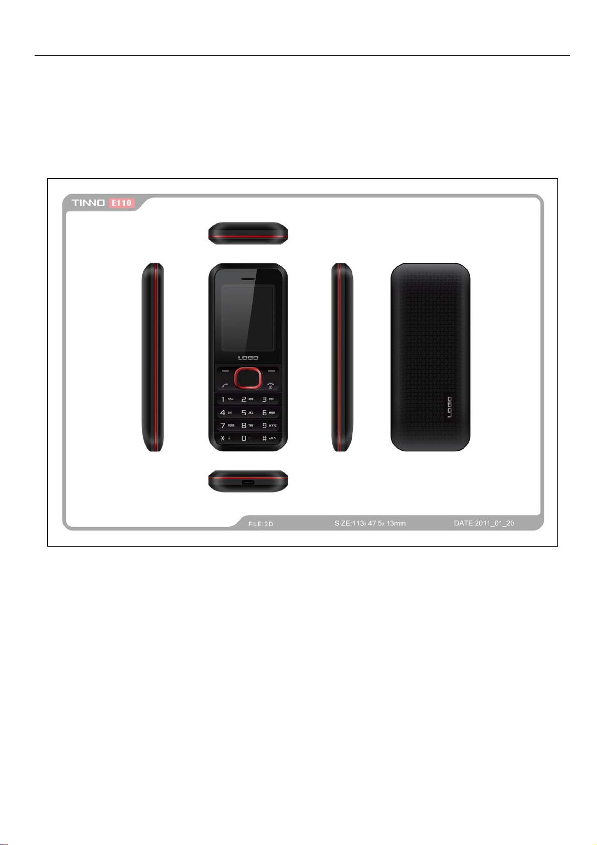
Service Manual
1
Page 2

Introduction
The purpose of this document is to help service workshop technicians to service products. This service
manual must be used only by authorized service suppliers. The content of it is confidential. Please note
that provides other guidance documents for service suppliers. Follow these regularly and comply with the
given instructions. While every effort has been made to ensure the accuracy of this document, some errors
may exist. Please keep in mind also that this documentation is continuously being updated and modified,
so always watch out for the newest version.
CAUTIONS
1、 Please read this service manual carefully and make sure all elements of anti-static are in place before
the repair work is carried out.
2、 Servicing and alignment MUST be undertaken by qualified personnel only.
3、 Please use specified tools and equipments for servicing, in which the parameters need to be calibrated
with specified criteria.
Chapter 1 Product Specification………………………………………………………………………….….3
Chapter 2 Explosive View………………….…………………………………………………………….….4
Chapter 3 Tools…………………………..……………………………………………………………….….5
Chapter 4 Guidance of Disassembly/Assembly............................................... .... .... ................................6~8
Chapter 5 Pictures of PCBA…………………………………………………………………………….9~10
Chapter 6 System block diagram……………………………………………………………………...…...11
Chapter 7 Circuit diagram for each unit………………………………………………………….......12~18
Chapter 8 Troubleshooting Guide…………………………………………………………………....19~24
Chapter 9 Guidance of Firmware Upgrading & Write IMEI………………………….……..............25~33
Chapter 10 CIT Testing…………………………………………...……………………………………….34
Content
2
Page 3
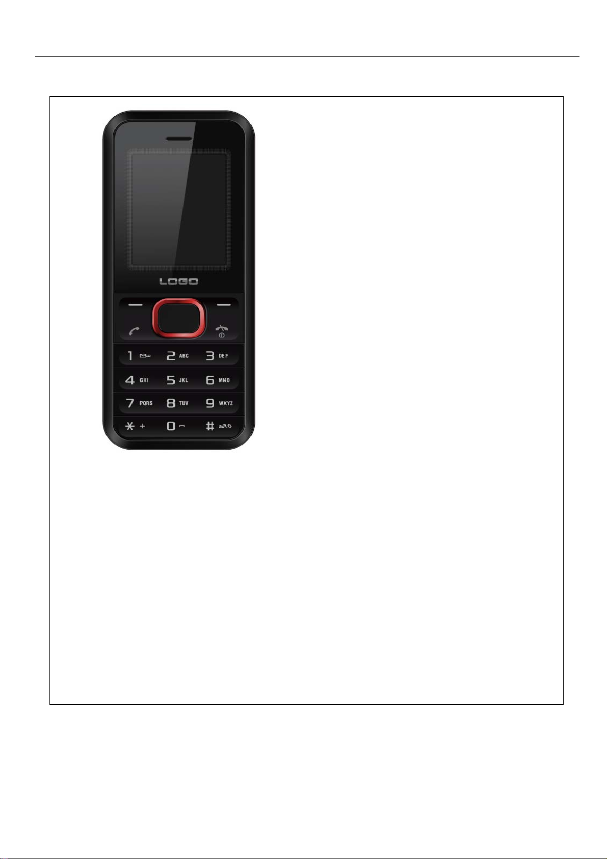
Specification:
Network: GSM/GPRS 900/1800 or 850/1900MHz
Display: 1.8“TFT QQVGA
Radio:FM radio FM Record to T-Flash
Talking time:570Min*
Standby time:289H*
Lithium Battery: Standard(1000mAh)
USB Charging:USB 1.1
*The actual time shall vary depending on the network situation
Chapter 1 Product Specification
Main features and functions
Dual SIM Dual Standby Single Connection
FM Radio
Multi-Media
USB 1.1 data transfer
T-Flash(Support 8G T Card)
1.8“TFT QQVGA
MP3/ AVI
3
Page 4
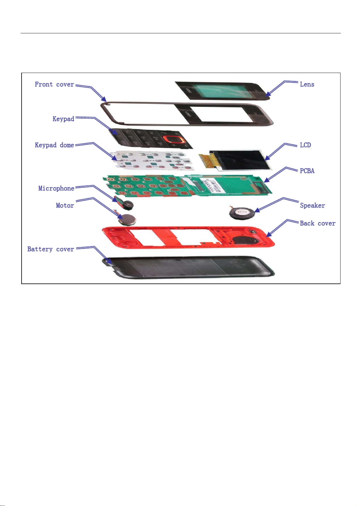
Chapter 2 Explosive View
4
Page 5
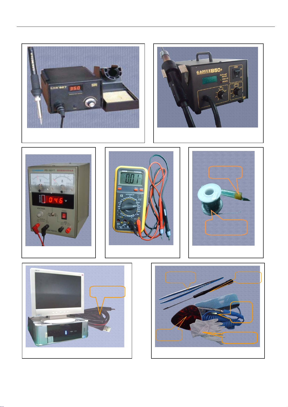
Chapter 3 Tools
lron
Voltage regulator
Computer and software download cable
Software
Multi-meter
850 heater
Solder wire
Soldering paste
Solder wire, soldering paste
tweezers
pick
tweezers、screwdriver、pick、wrist strap
Screw
Wrist
strap
Writ strap
5
Page 6
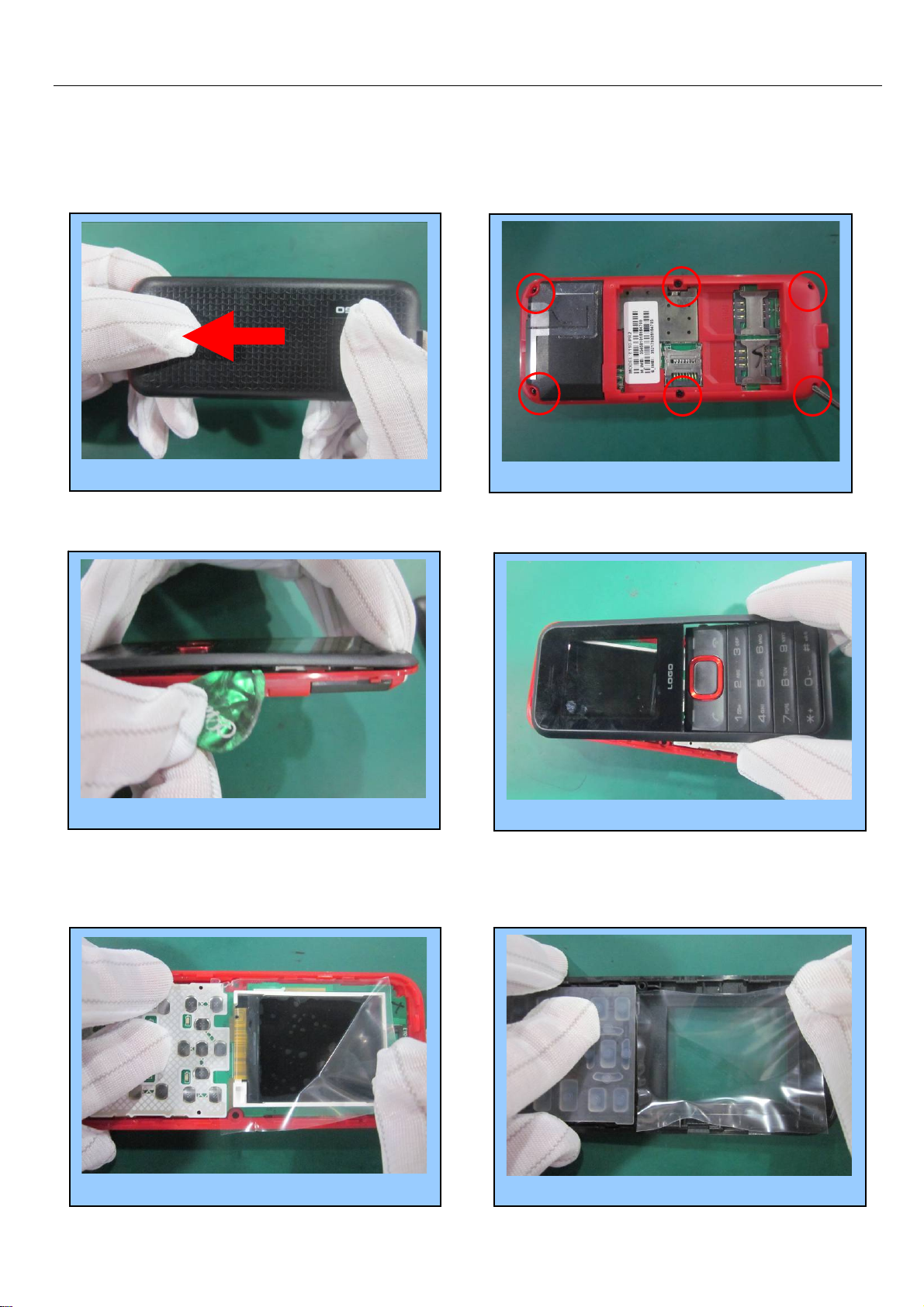
Chapter 4 Guidance of Disassembly/Assembly
4.1
Disassembly
Push out the battery cover from left 1
Prize up the middle housing 3
Stick LCM protection film 5
Unfasten the 6 screws by screwdriver 2
Take out the front cover 4
Stick lens protection film 6
6
Page 7
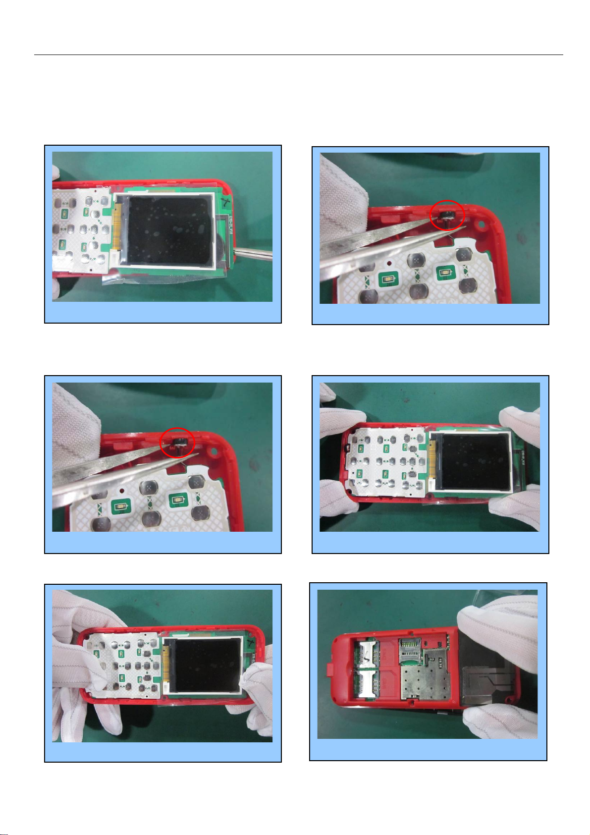
Prize up the PCBA by
4.2
Assembly
Tighen the main PCBA 3
tweezers 7
Take out the microphone by tweezers 8
Install main PCBA in back cover 2Install the microphone by tweezers 1
Install the back cover 4
7
Page 8
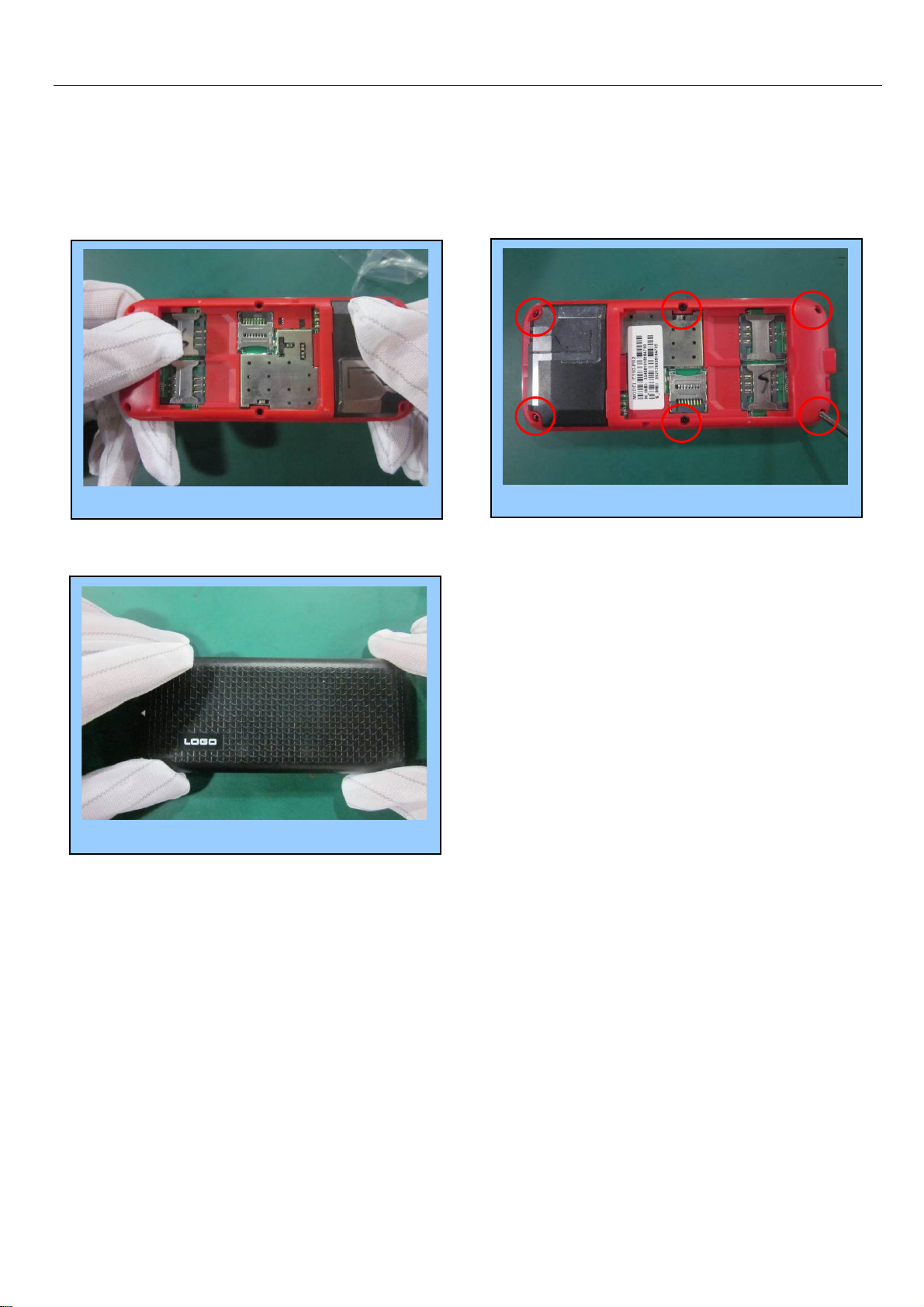
Tighen the back cover 5
Install the battery cover 7
Finish……….
fasten the 6 screws by screwdriver 6
8
Page 9
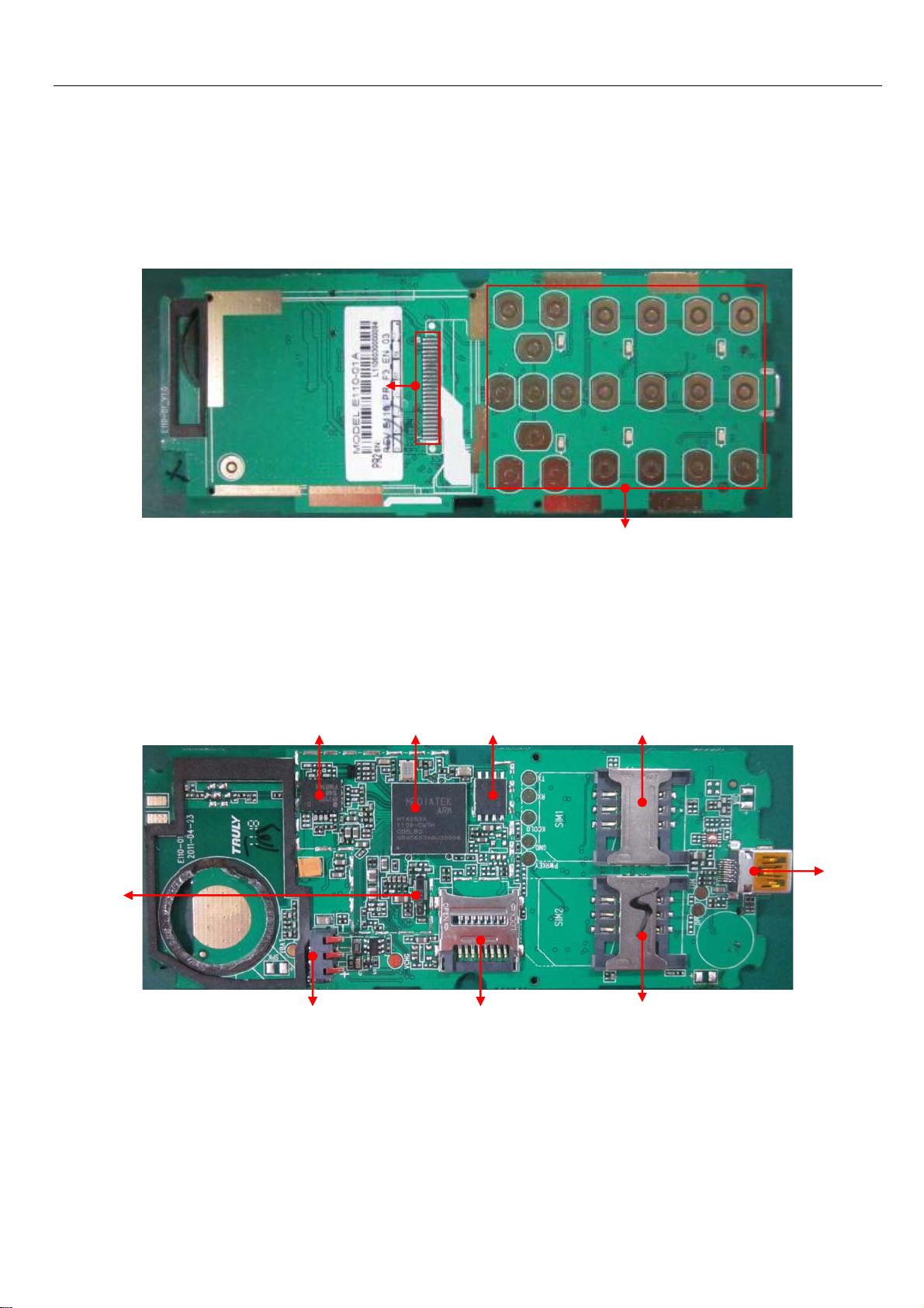
Chapter 5 Pictures of PCBA
5.1 Pictures
5.1.1 Instruction & location of main components on side A.
5.1.2 Instruction & location of main components on side B.
X201 crystal
32.768K
1
LCD Connector
U502 PA
RF7170
J201 battery
Connector
U101 CPU
MT6252
J301 T-FLASH
Connector
U301
Flash IC
Keypad connector
A 面图
J502 SIM
Connector
J302 I/O
Connector
J503 SIM
Connector
9
Page 10
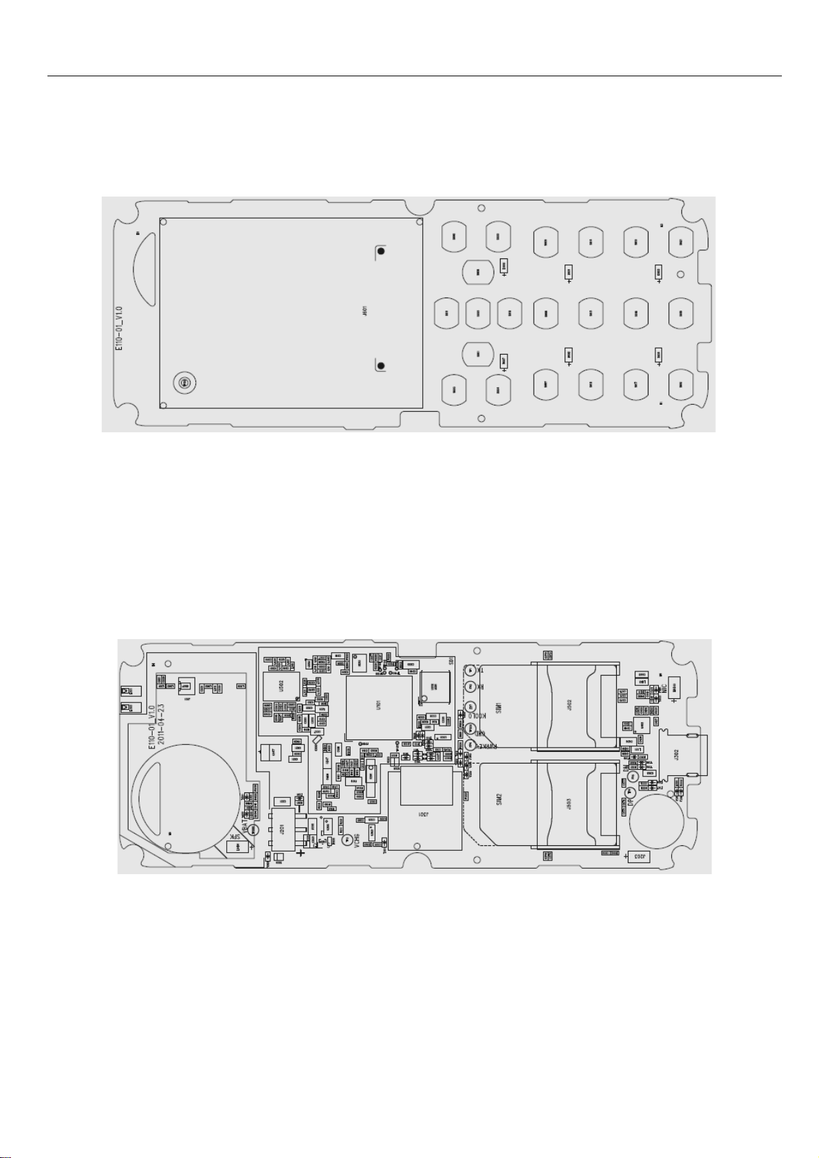
5.2 Layout
5.2.1 Layout of PCBA side A
5.2.2 Layout of PCBA side B
10
Page 11
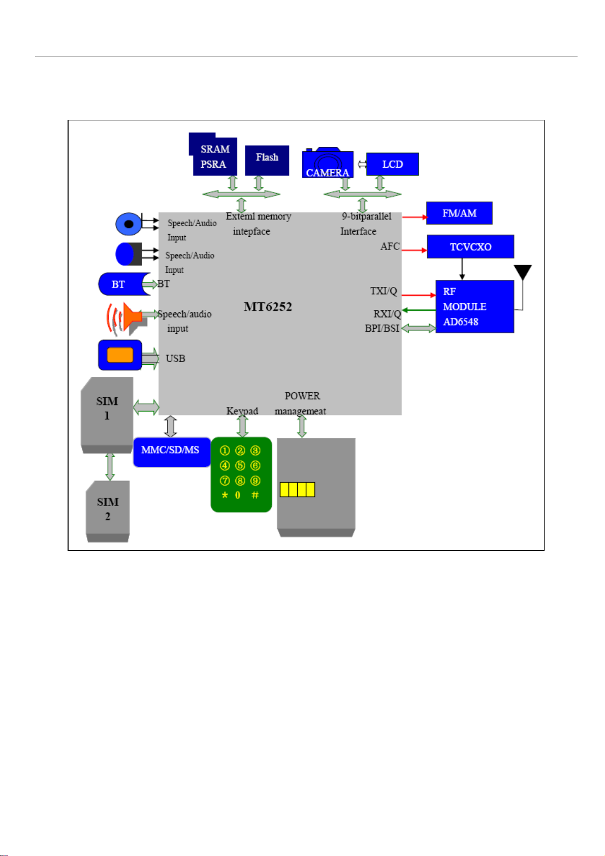
Chapter 6 System Block Diagram
11
Page 12
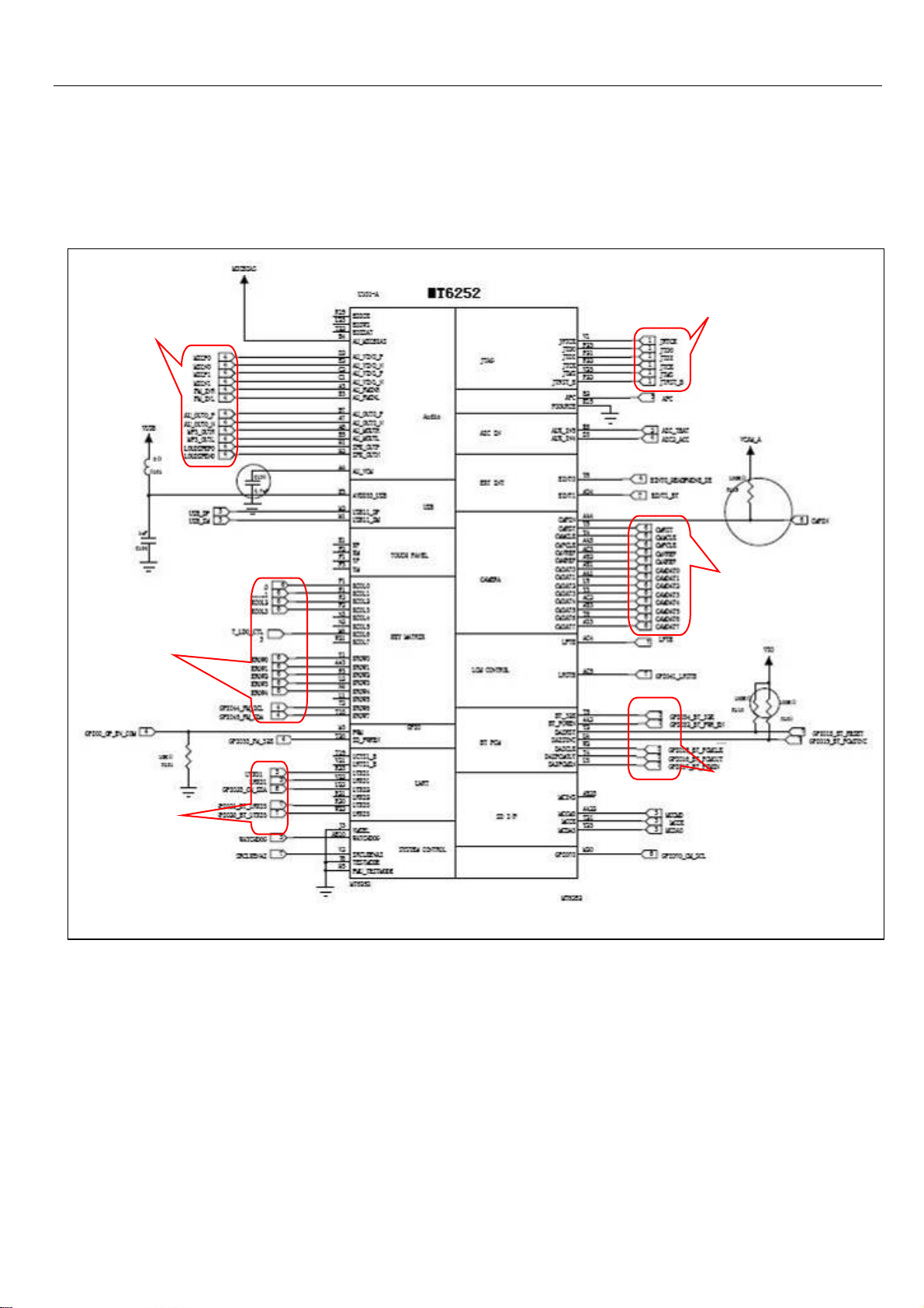
Chapter 7 Circuit Diagram for each unit
7.1.1 CPU & Baseband
Audio process
Keypad interface
O/I
Interface
JAVA
Process
CAMERA
Interface
BT
Module
12
Page 13
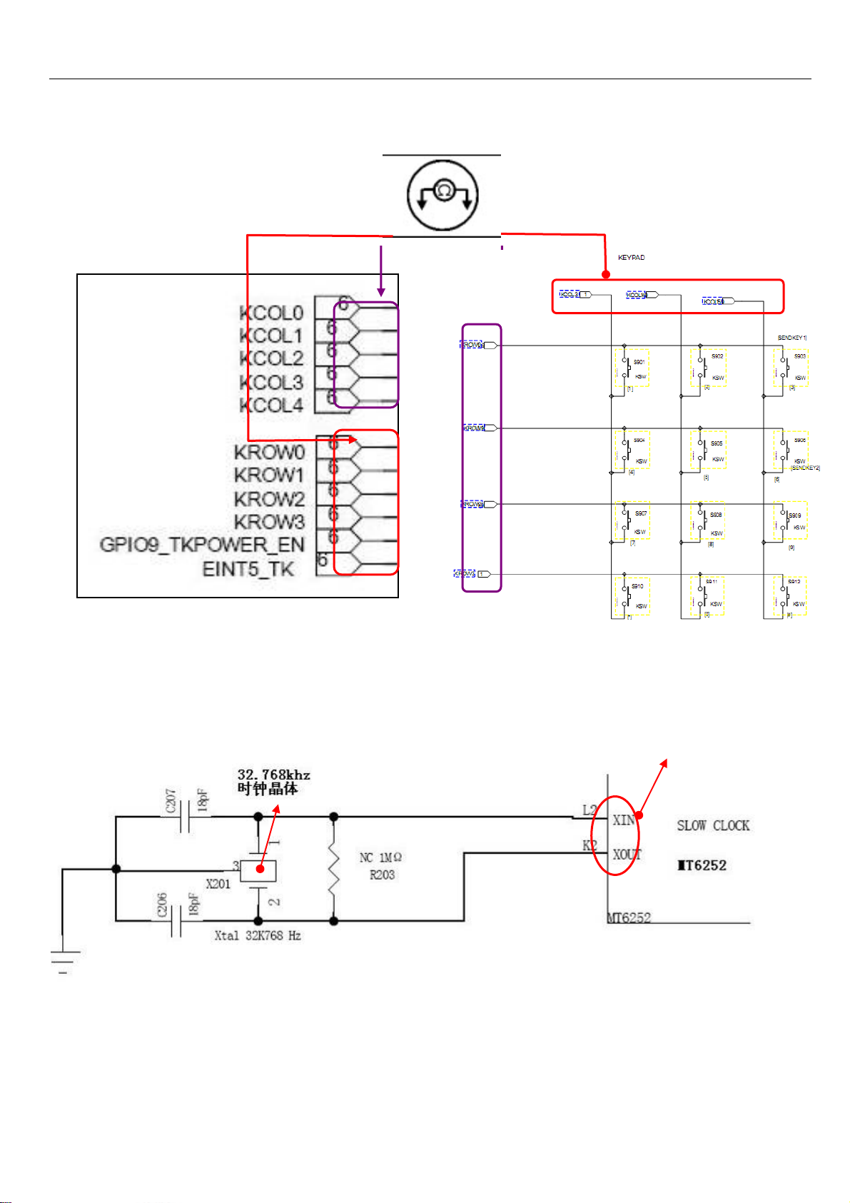
7.1.2 Keypad input interface
7.1.3 32.768KHZ clock crystal circuit
Clock Signal I/O
13
Page 14
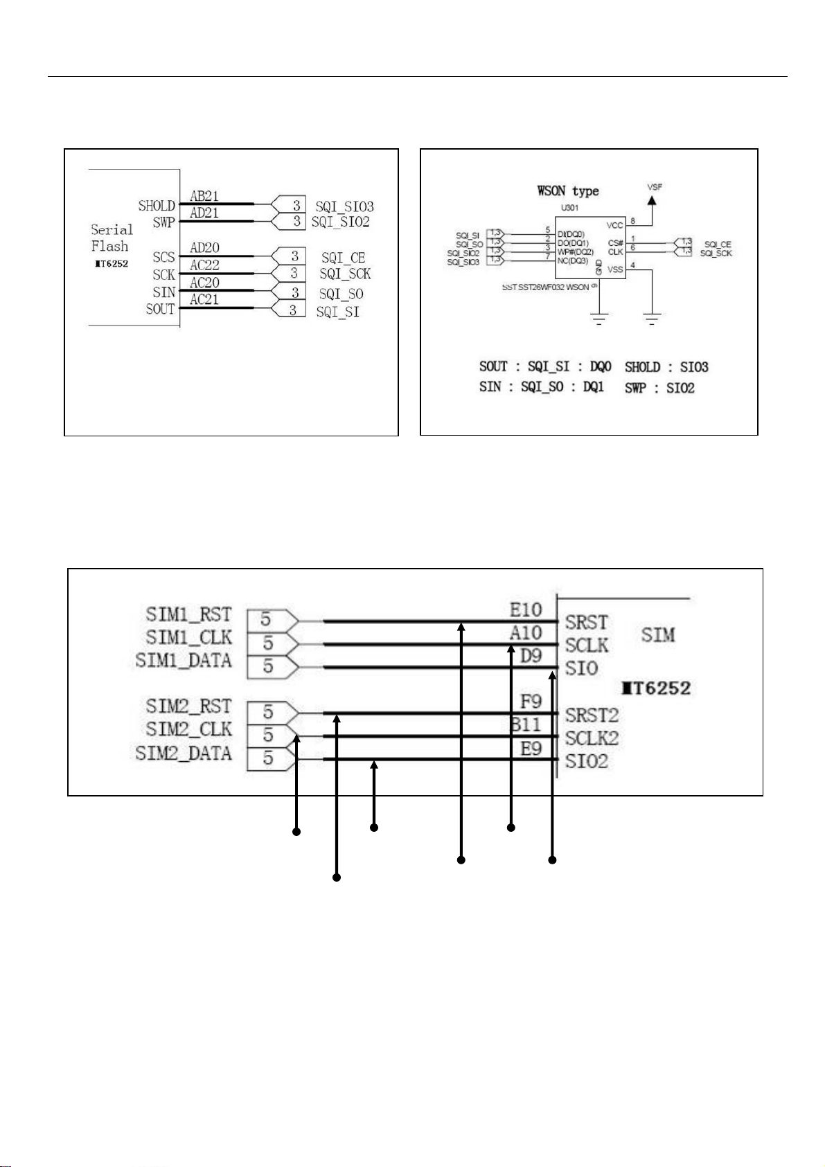
7.1.4 Data line of CPU and Flash
FLASH data transfer
7.1.5 Output of SIM
SIM 2 Clock
SIM 2 Data SIM 1 Clock
SIM 2 Reset
SIM 1 Reset
SIM 1 Data
14
Page 15
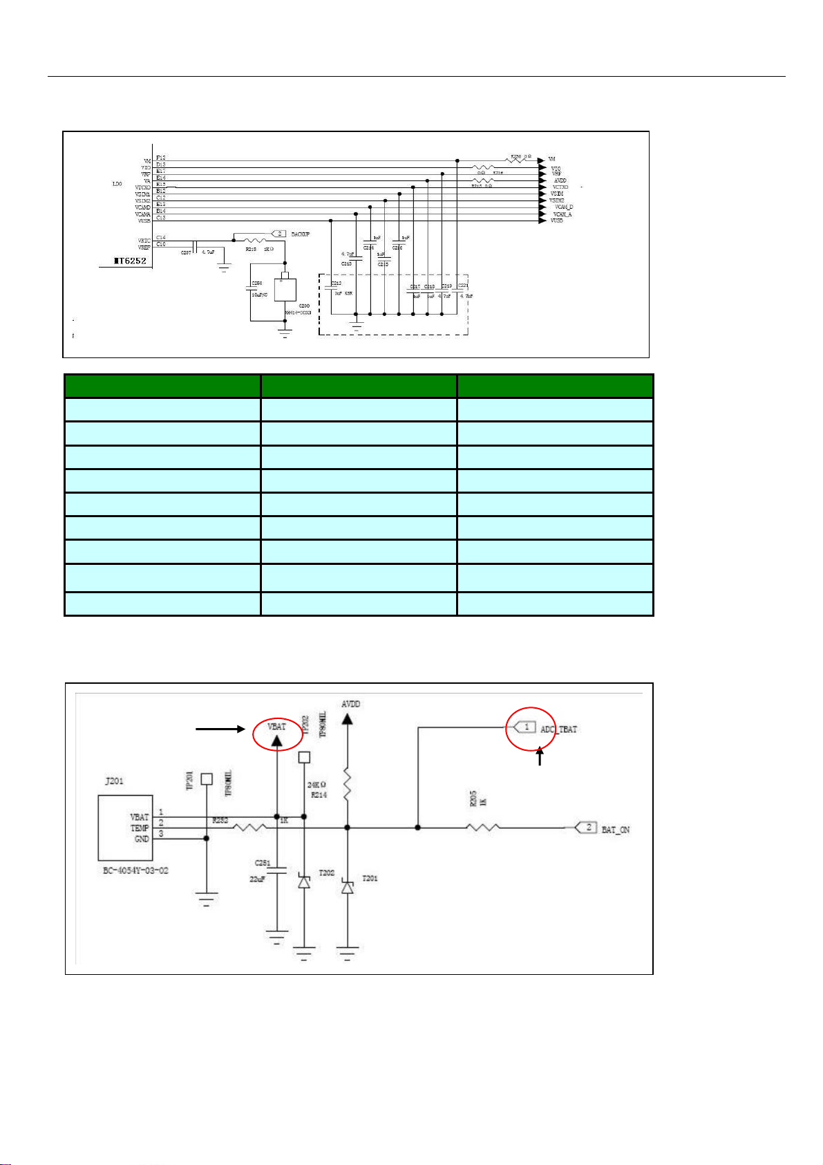
7.2 Power output of MT6252 CPU
item voitage current
Vcore 1.2v 200ma
Vio 2.8v 100ma
Vadd 2.8v 150ma
Vtcxo 2.8v 20ma
Vrtc 1.2v 200ma
Vmem 2.8v 150ma
Vsim 2.8v 20ma
Vcs 2.8v 200ma
vcs 1.8v 150ma
Positive Voltage
Supply
Charging Temperature
Detector
15
Page 16
g
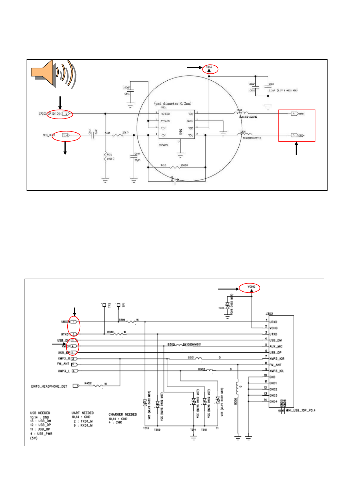
7.3 Audio Amplifier U201
3.7V Power
Supply
Audio Start Signal
Audio Signal Input
Audio Signal Output
7.4 I/O Interface (10PIN)
Firmware
Downloadin
Charging
Voltage Input
Data
Transfer
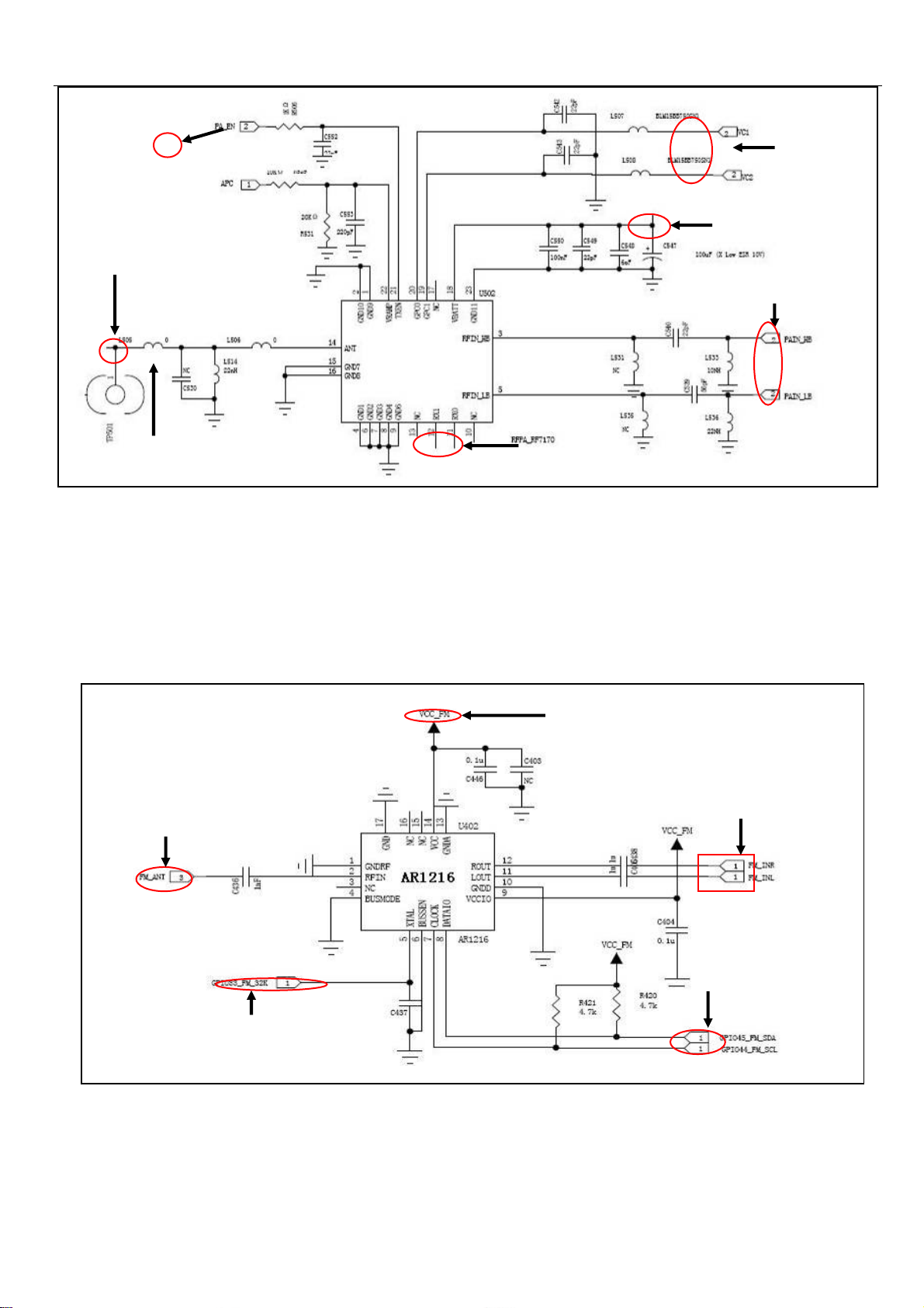
7.7 Power Amplifier
16
Page 17
Antenna
7.5 FM Radio Modules
The AR1216 processes the FM broadcasting signal that received from antenna (FM/ANT) ,produces and sends
audio signals (FM-INL, FM-INMR) to the audio process module of CPU for decoding, where the electrical signals of
audio are made.
Antenna
32KClock signal input
RF7170
Receive Signal Output
2.7V Power Supply
Power Supply
RF Signal Input
Audio output
Data Communication Port
Frequency Band
Selection
17
Page 18
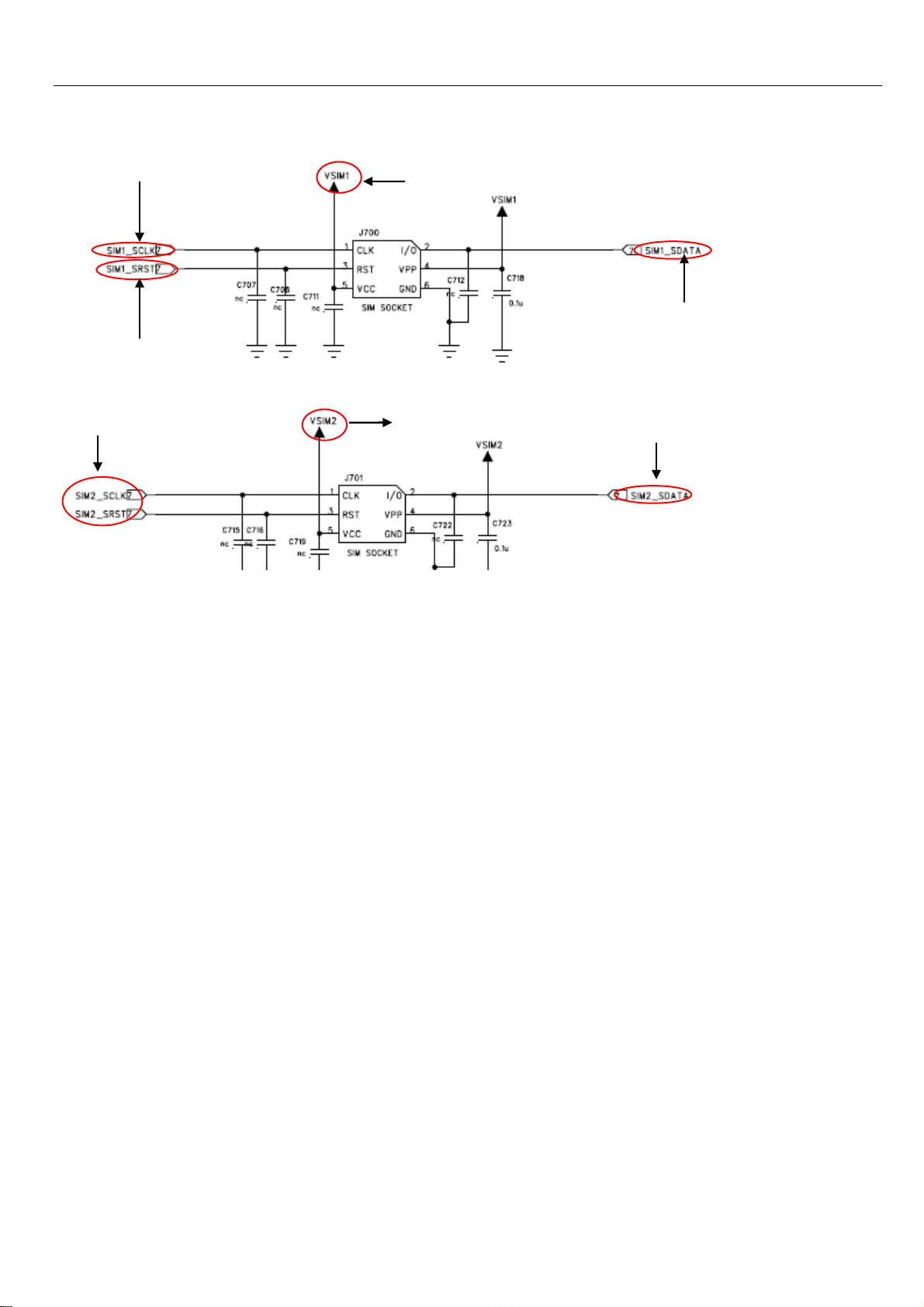
7.6 SIM Circuit
SIM 1Clock
SIM 1 Reset
SIM 2 Clock, Reset
SIM 1 Power Supply
SIM 2 Power Supply
SIM 1 Data
SIM 2 Data
18
Page 19
r
g
gh(
g
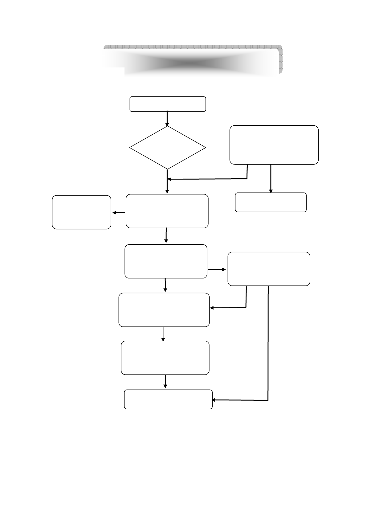
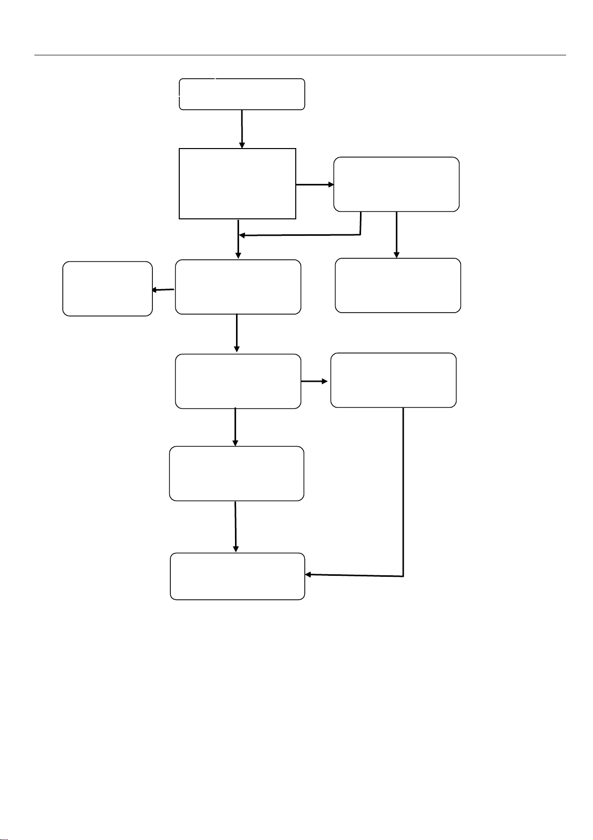
Cannot Download Firmware
Chapter 8 Troubleshooting Guide
Cannot download
Can power
on?
YES
YES
OK
Check software
configuration, cable,
power supply, software,
NO
Replace or
Re-solder I/O
connecto
YES
Check if I/O connector
is false weld or
dama
ed
NO
Change or reconfigure
Plug the cable and
check if the current is
hi
normally 30mA)
NO
Check if CPU has power
output and open circuit
YES
Unplug the cable and
check if the chipset is
overheated
NO
YES
NO
Check VCORE、VDD、VADD、
VTCXO、VRTC、VMEM、test
26MHZ、32KHZ Clock si
nal
Replace U101
19
Page 20
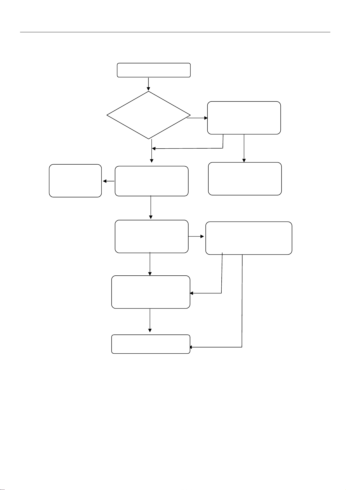
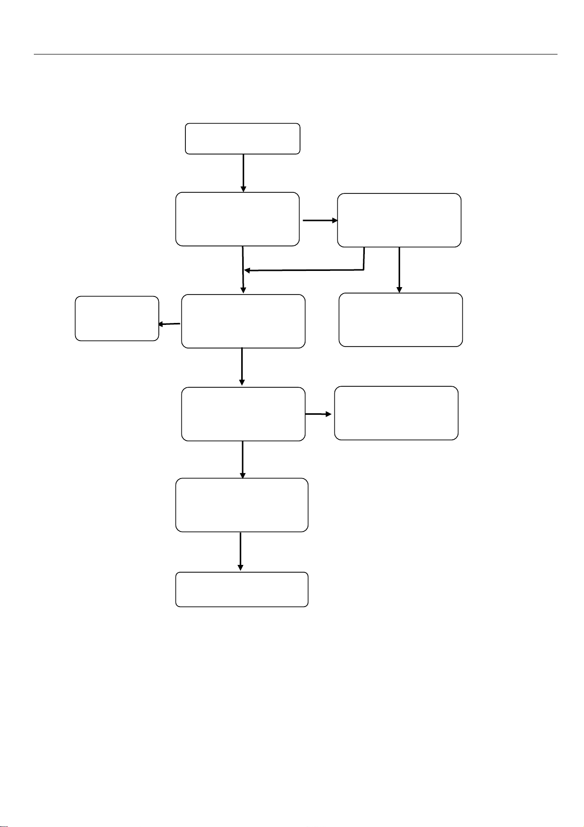
SIM cannot be recognized
SIM is not recognized
Are SIM contacts
broken?
NO
Clean or change SIM
slot
YES
NO
OK
Change SIM
YES
Is SIM invalid?
NO
Use power regulator
to test if the current
is normal.
NO
YES
Problem Solved
CPU MT6252 is possibly false
soldered or damaged.
NO
YES
MT6252 is broken
Change U101 MT6252
20
Page 21
g
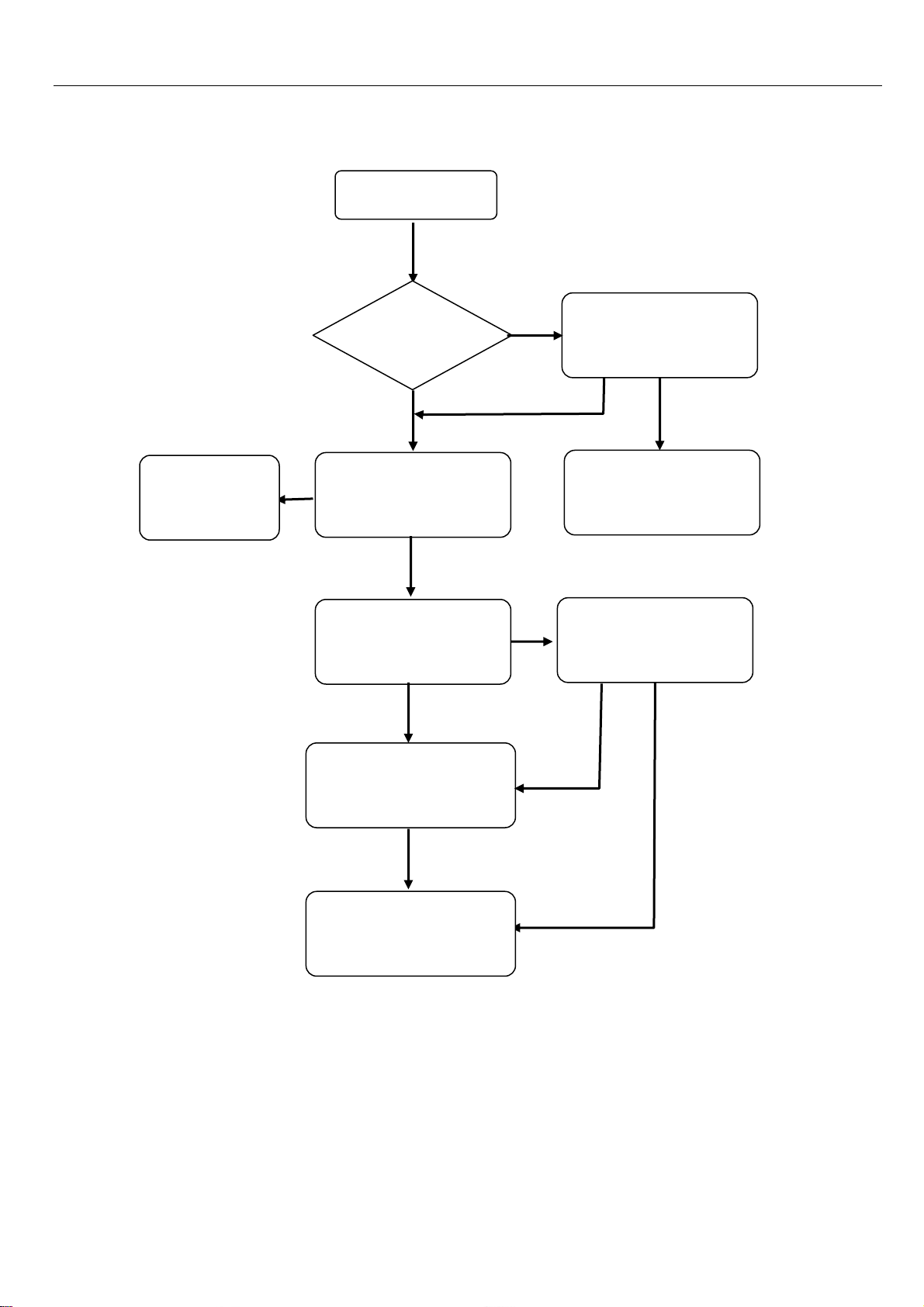
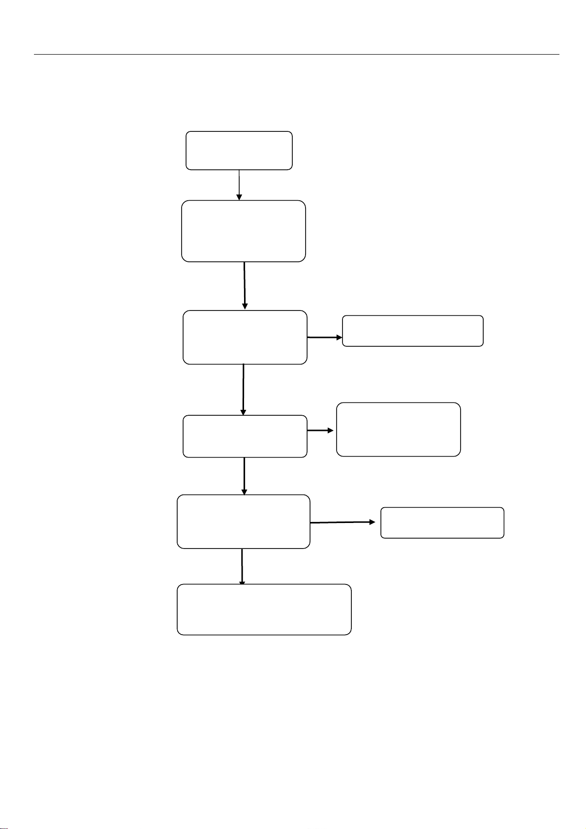
Cannot Power On
Change battery
YES
Cannot Power On
Check battery
Contacts J201
YES
Try to power on when
connect to the power
re
ulator
NO
Check if the current
is around 30~40MA
NO
MT6252 is broken
Change U101 MT6252
NO
YES
Re-solder or change
J201
NO
Problem Solved
Firmware upgrading
NO
YES
YES
21
Page 22
Receiver No Sound
Change
receiver
YES
Receiver no sound
Check hand free mode
(Speaker) is ok
YES
Check if the receiver
is broken.
NO
Test receiver by
using power supply,
if there is sound of
YES
Test if LS401 with
Oscillograph when on
the call.
NO
Change CPU MT6252
NO
NO
Check if LS401 is
broken.
NO
Clean or Re-solder
LS401
Change receiver.
YES
NO
22
Page 23
grap
pply
No Incoming Ring
Cancel mute.
YES
No incoming ring
*#84666*#, Option7,
test ringtone
YES
Check if handset is
set to mute.
NO
Check if the volume is
set to lowest level.
NO
Test the LS401 when
ringing is on by using
oscillo
NO
Change U101 or U401
h.
NO
YES
Remove receiver and
test with power
su
YES
to see if there
NO
Change speaker
Turn up the volume
23
Page 24
Display Problem
Display problem
Check if the LCD is
broken or liquid
leaked.
NO
Check the LCD
contacts.
YES
Change LCD
NO
Check if the pin13 of
J705 has signal and the
connector is normal.
NO
Change or re-solder U101 MT6252
NO
YES
YES
Clean or Re-solder J705
Problem solved
Firmware upgrading
24
Page 25
Chapter 9 Firmware Upgrading Guide
9.1 Firmware Upgrading
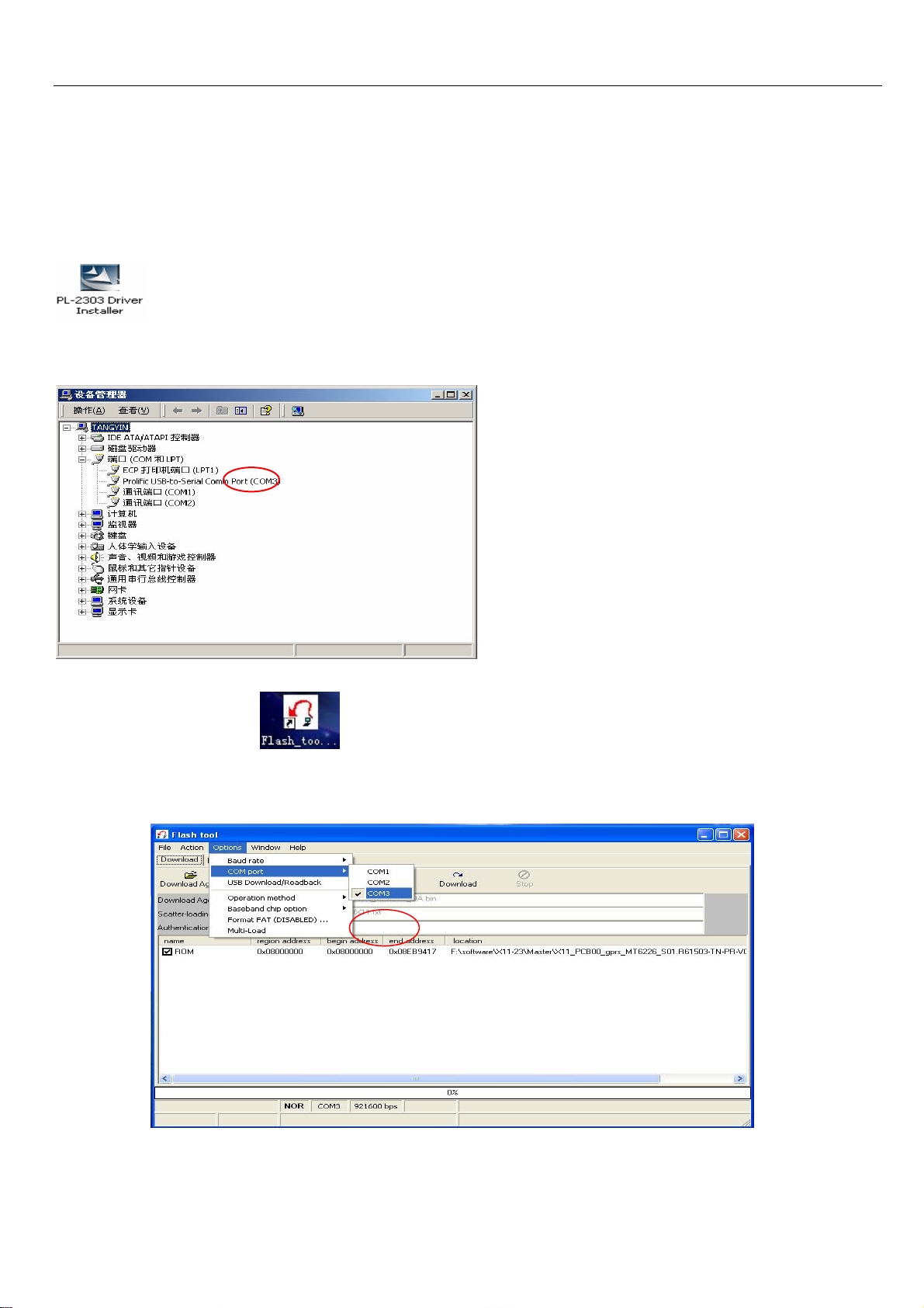
9.1.1 Install USB driver
The maximum downloading speed can be up to 921600bit/s when using USB-Serial cable.
The driver needs to be installed before using the USB cable.
Please keep the USB cables unplugged when installing the driver.
Plug the USB cable when installing is completed. And check device manager of the PC.
9.1.2 Run “FlashTool_v3.2
9.1.3 Please select “Options”-“COM port”-Choose the port which is same as the one in “Device Manager”
25
Page 26
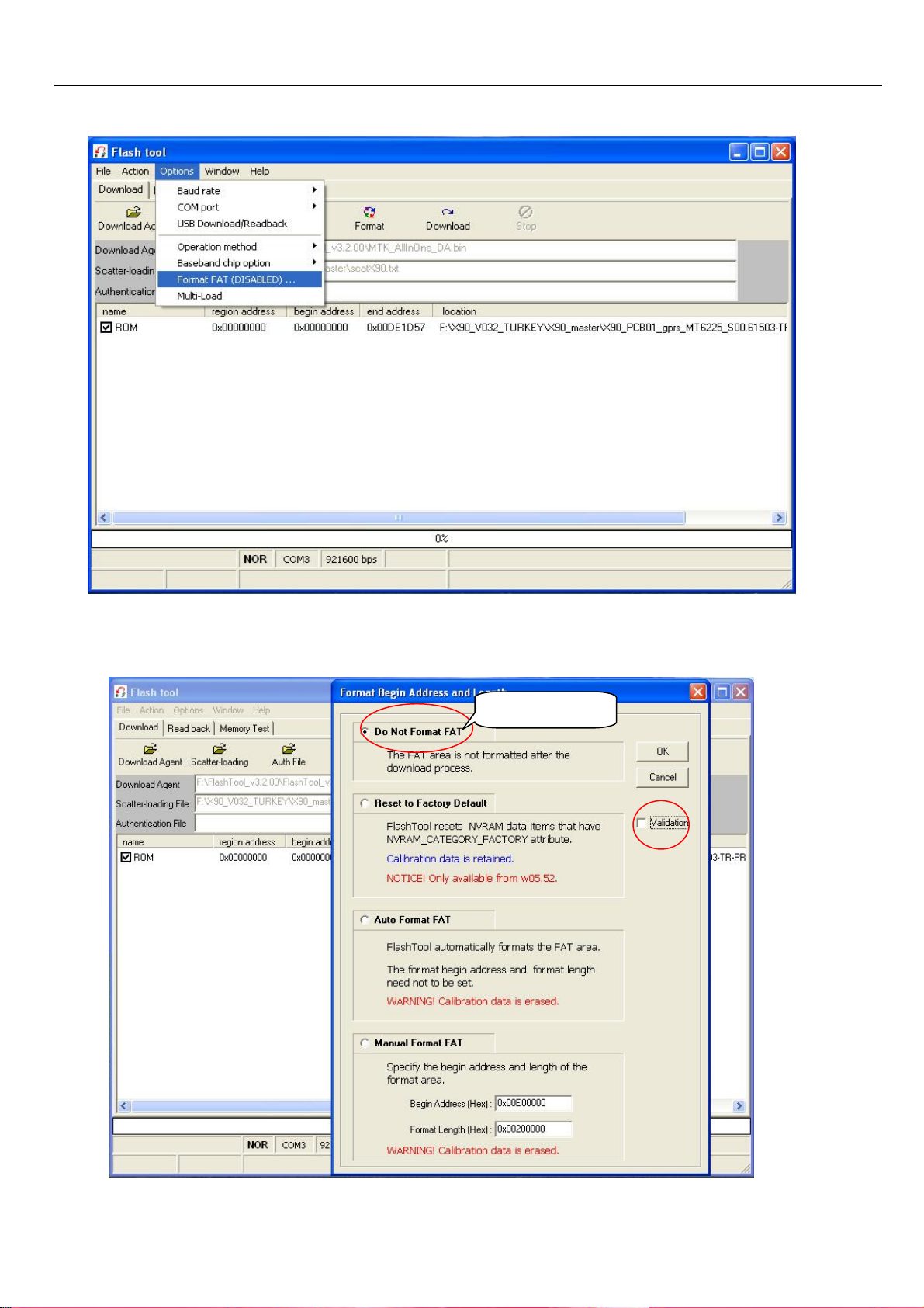
9.1.4 Select “Options”-“Format FAT (DISABLED)…” and please do NOT select “validation”.
9.1.5 Please select “Do Not Format FAT”.
Select this one
26
Page 27
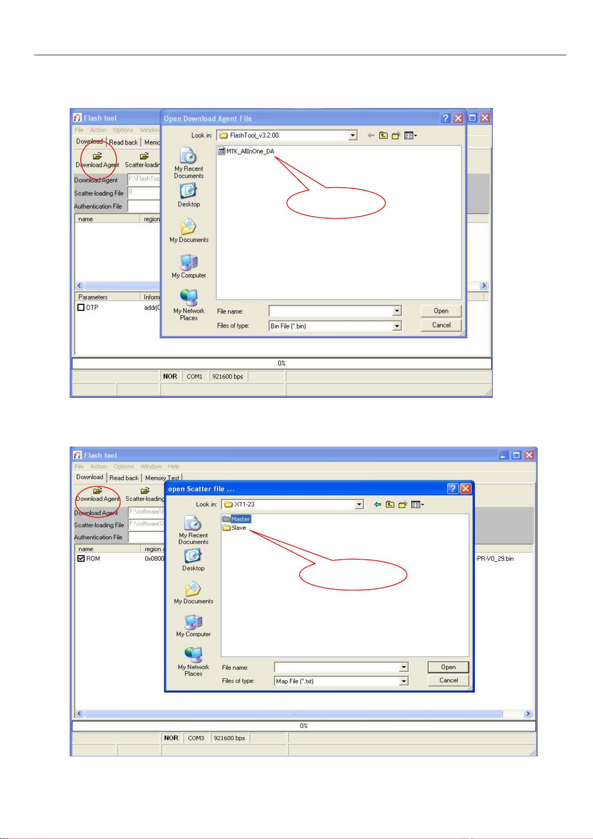
9.1.6 Click “Download Agent” and select “MTK-ALLInOne.bin”
9.1.7 Click “Scatter-loading” and select “scatX11-23.txt” file.
Double click
Double click.
27
Page 28
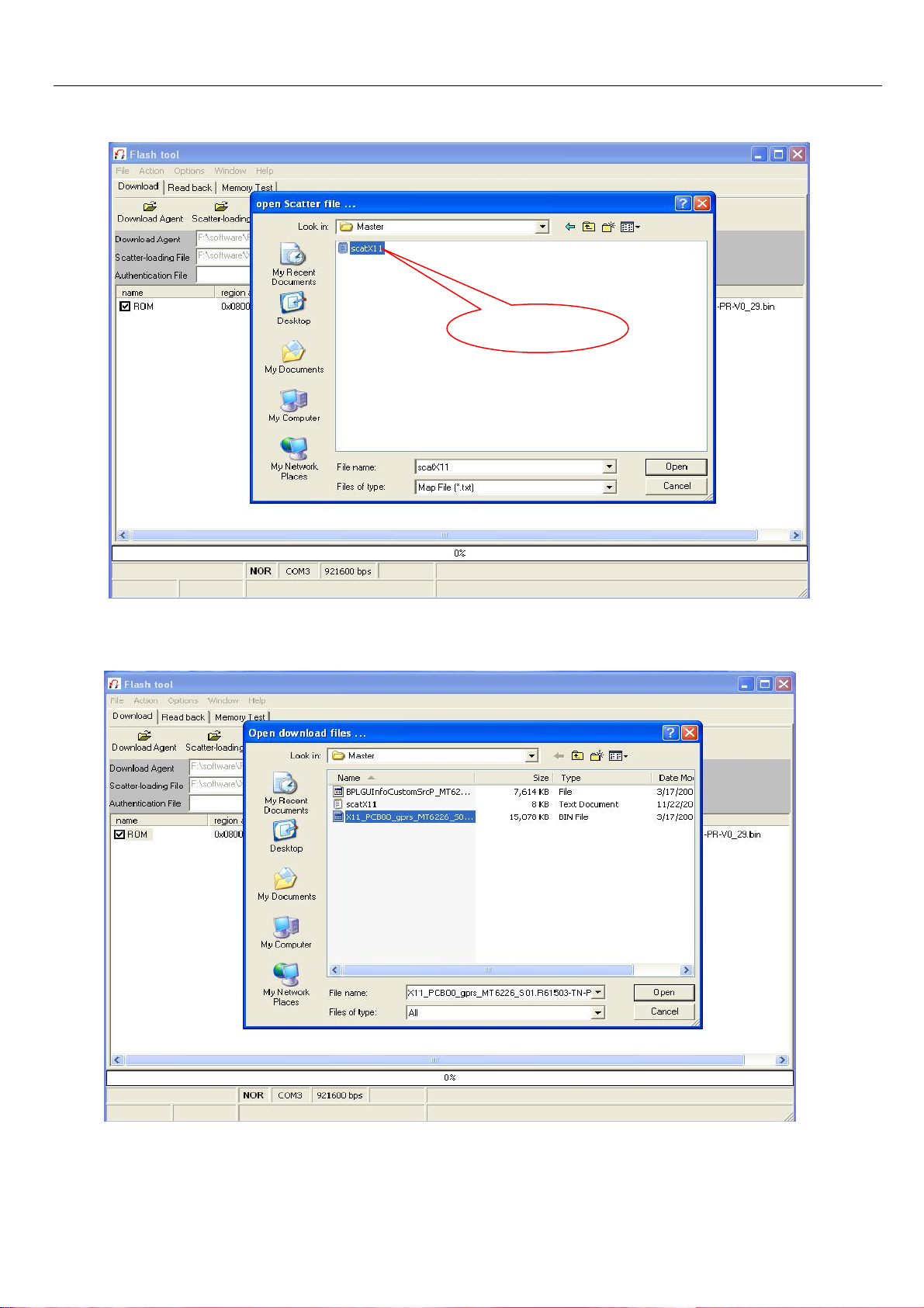
9.1.8. Click “ROM” and select “X11-23_PCB00_gprs_MT6226_S01. Bin” file. Note: Please use the latest version.
Double click
双击
28
Page 29
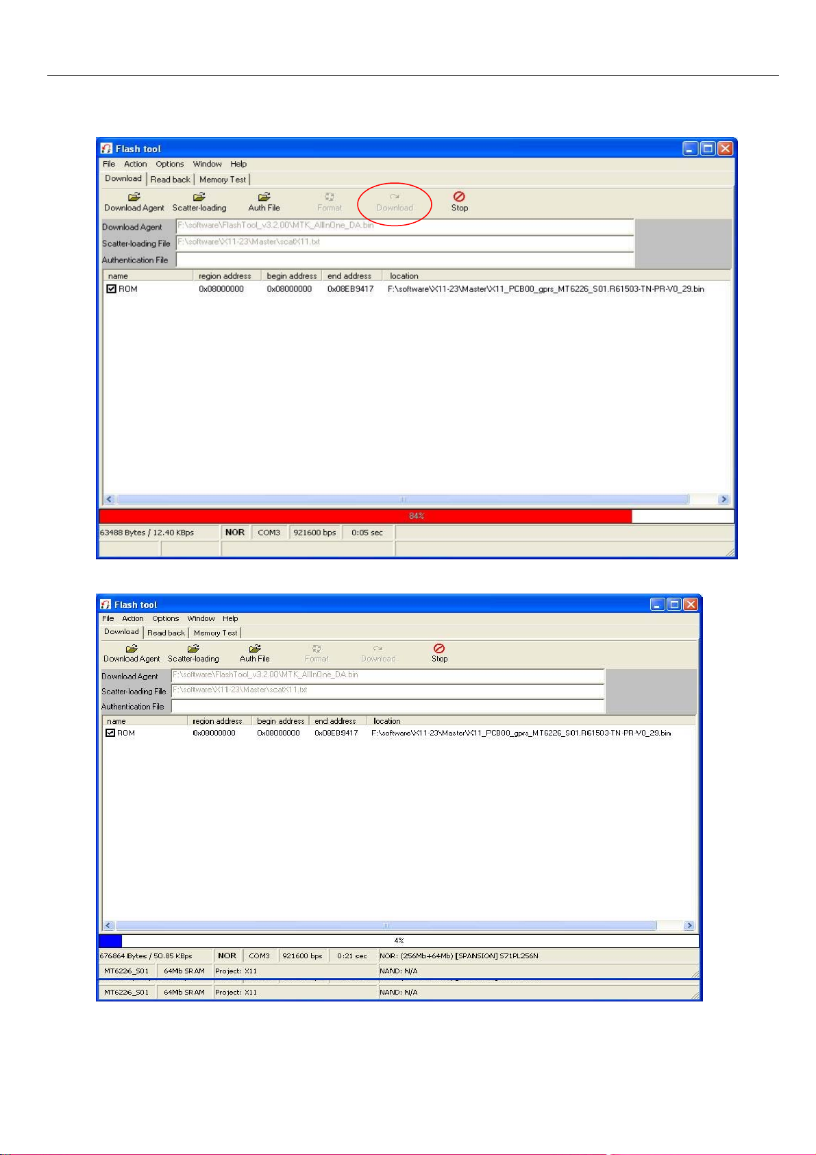
9.1.9 Power off the handset, remove the battery, click “Download”, and connect the cable with handset, then insert the
battery, press the power on button, the red and blue progress bar shall appear.
.
9.1.10 Downloading is in process.
29
Page 30
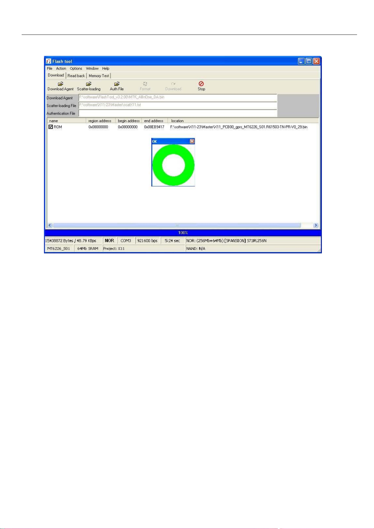
9.1.11 Downloading is completed.
30
Page 31
9.2 IMEI Writing Guide
How to use IMEI_Writer to write IMEI
General
The IMEI_Writer software should be used in a Windows XP operation system. The pictures in this document help to
understanding, and thy may not be exactly the same as showed in your computer.
1. Write IMEI to the slave phone of MGSM 41B phone to give an example.
1.1 firstly, plugs the correct upgrade cable to the computer. This is necessary, or the software will not be run
normally.
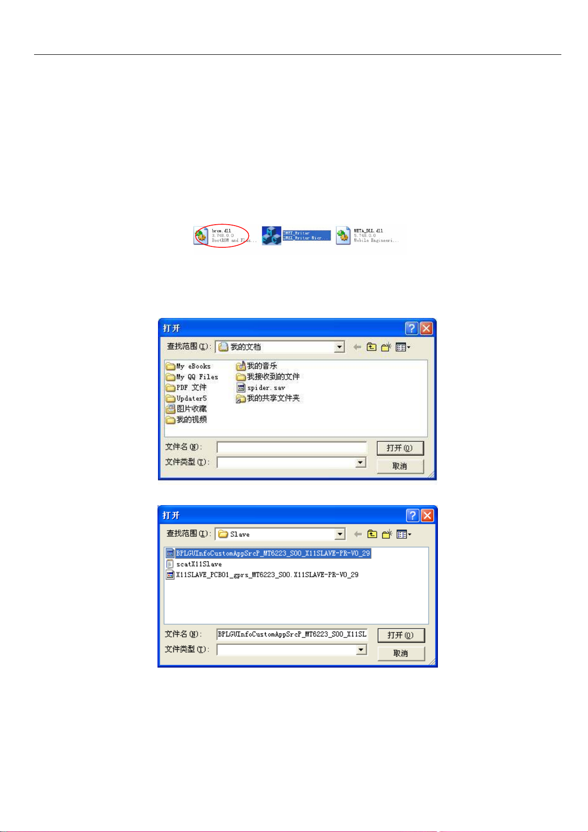
1.2 double-clicks the logo in figure 1-1 to run the IMEI Writer in a Windows XP operation system.
Figure 1-1
For the first time you run IMEI_Writer in the computer, figure 1-2 occurs. Choose the right database file for the slave
phone of MGSM 41B phone referring to figure 1-3.
Figure 1-2
Figure 1-3
31
Page 32
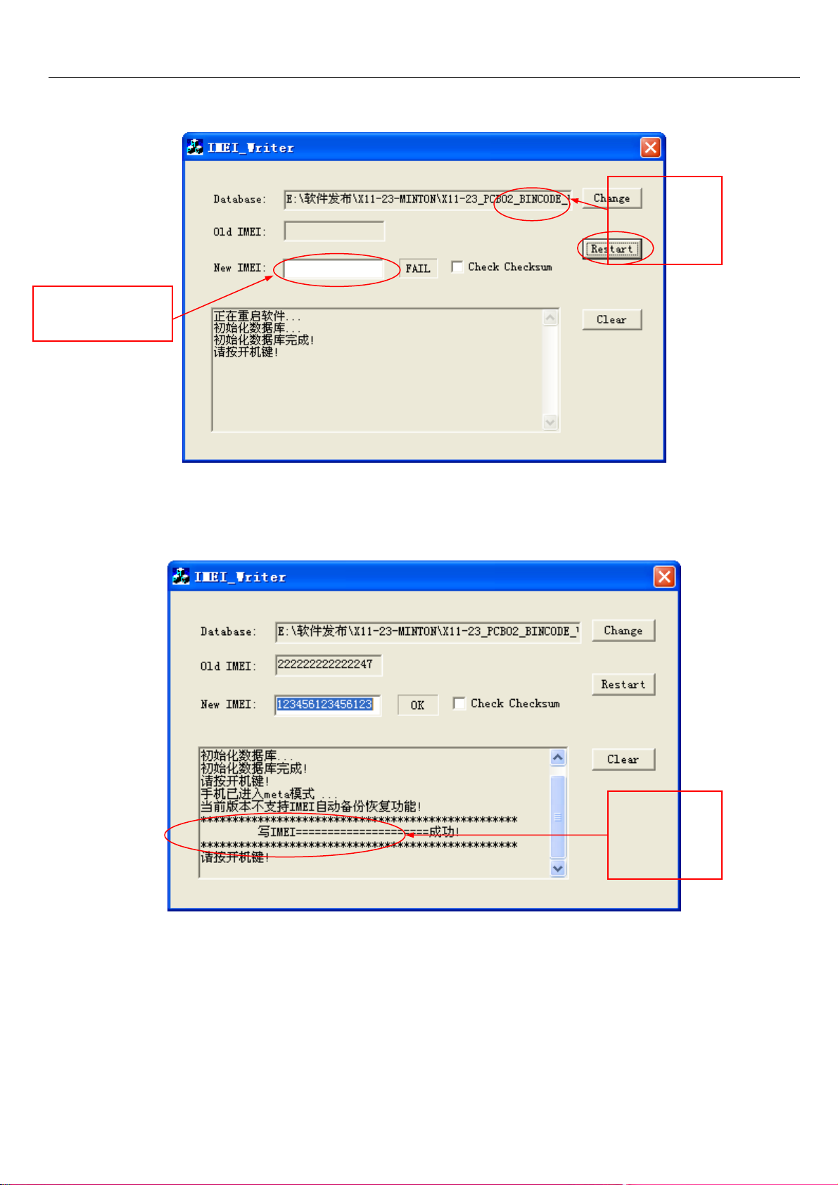
1.2 input the IMEI of the slave phone referring to figure 1-4, click “Restart”, after 3 seconds plug the slave phone
cable connector to the phone and power on the phone.
Click here to
change the
database file
Input the IMEI
here
Figure 1-4
1.3 after several seconds, figure 1-5 occurs to show the slave phone is written to the phone successfully.
Showing
writing IMEI
successfully
Figure 1-5
2. Write the IMEI of the master phone.
If necessary, you can also use IMEI_Writer to write IMEI to the master phone conveniently.
32
Page 33

2.1 Change the database file to be for the master phone, referring figure 1-4.
2.2 Input the IMEI of the master phone, click “Restart”, after 3 seconds plug the master phone cable connector to
the phone and power on the phone.
2.3 after several seconds figure 1-5 occurs to show the slave phone is written to the phone successfully.
3 write the IMEI of another phone
If the right database file has already been chose, click the “restart”, input the IMEI of the phone, click “Restart”, after
3 seconds plug the phone cable connector to the phone and power on the phone. After several seconds, figure 1-5
occurs to show the slave phone is written to the phone successfully.
33
Page 34

Chapter 10 CIT Testing
Input “*#84666*#” when in the standby mode:
1、Version: Confirm the firmware version.
3、Echo Loop: Receiver shall produce sound when blowing over the mic.
4、Keypad: Press every button on the handset until the screen is clear.
5、Vibrator:Press “start” then the vibration shall start.
6、Lond SPK: Press “start” the speaker shall work.
7、Ringtone: Press “start” the ringtone shall be played.
8、LED:Press “OK” to test the LED.
9、LCD: Select “Auto Display” LCD shall perform the self-testing.
11、Receiver:Press “start” the receiver shall produce sound.
Camera: Menu- Camera, test the capture and shooting, no need to save.
34
 Loading...