

Page 1
Y8846S/Y8846D
Rack Mount Kit
Instruction Sheet
®
Introduction
This sheet provides instructions for mounting the
Fluke 8845A and 8846A multimeters (hereafter
referred to as the Meter) in a standard 19-inch rack
panel using the Fluke Y8846S or Y8846D Rack
Mount Kit.
Preparation
Before installing the rack mount kit, first remove the
handle, rubber boots, and three screws from the Meter
by performing the following steps:
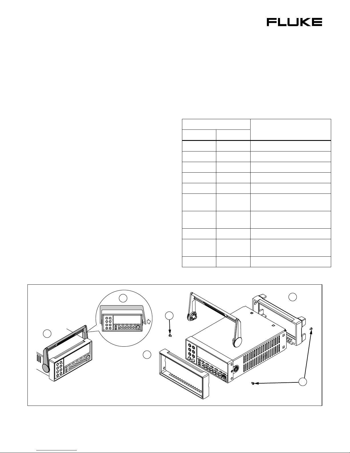
1. With the Meter flat on the desk, rotate the Meter
handle to the vertical position over the top of the
Meter as shown in Figure 1.
2. Remove the handle by pulling one side of the
handle outward, away from the Meter until free,
as shown in Figure 1. Then pull the other side of
the handle out, away from the Meter.
3. To remove the boots, pry and pull them from the
Meter.
4. Remove the two side screws and one rear screw
(earth connection) from the Meter.
Table 1 lists the parts included with each Rack Mount
Kit:
Table 1. Parts List
Quantity
Description
Y8846S Y8846D
1 2 Small filler plate
1 NA Large filler plate
1 NA Large filler plate bracket
1 1 Rack mount tray
NA 1 Dual center mount
2 2
1 2
#8-32 x ½" panhead Phillips
screws
#6-32 x ¼" panhead Phillips
screws
4 4 #10-32 x ¾" Phillips rack screws
1 2
#6-32 x ½" panhead Phillips
screws
4 4 #10-32 rack nuts
BACK MEMORY
RANGE
1
2675612 October 2006 ©2006 Fluke Corporation. All rights reserved. Printed in U.S.A. 1
2
4
F1 F2 F3 F4 F5
INSTR
TRIG
DCV ACV DCI ACI
SETUP
MEAS
FREQ
ZERO
ANALYZE
TEMP
PERIOD
SETUP
3
Front Boot
Figure 1. Handle and Boot Removal
3
Rear Boot
4
caw501f.emf
Page 2
Y8846S/Y8846D
Instruction Sheet
Installing a Single Rack Mount
Kit
The Y8846S Dual Rack Mount Kit allows for the
mounting of the Meter on either the left or right side
of a standard 19-inch rack. The following steps
describe mounting the Meter on the left side of the
rack.
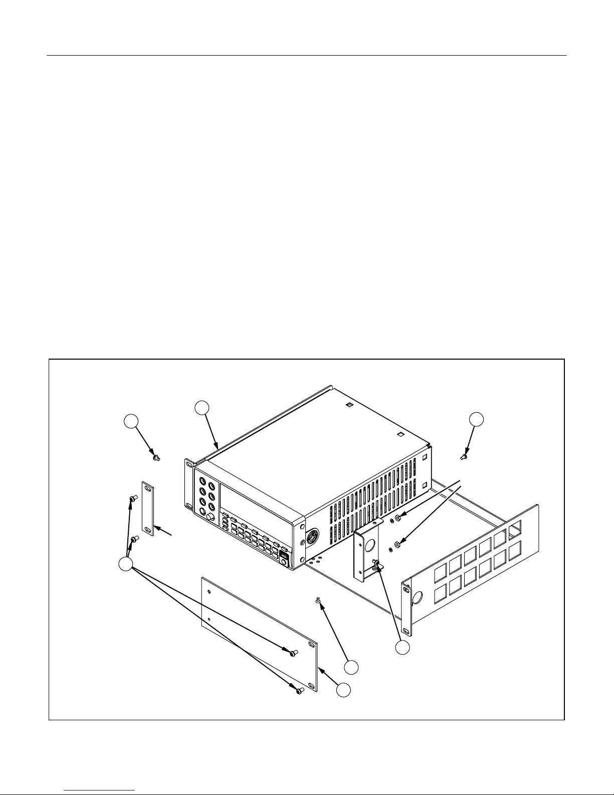
1. Using one #8-32 x ½" panhead screw, attach the
right angle filler plate bracket on the right front
side of the Meter, keeping the smooth face with
two holes of the bracket facing the front as shown
in Figure 2.
2. With the tray flat on a desk with the rack screw
ears toward you, place the Meter so the left side
of the front frame is against the left wall of the
tray.
3. Attach the Meter to the tray by inserting one #832 x ½" panhead screw through the left-hand
forward holes in the tray and into the side of the
Meter as shown in Figure 2.
4. Insert a #6-32 x ½" flathead screw through the
hole in the back of the tray and into the back of
the Meter as shown in Figure 2.
5. Attach the filler plate bracket on the right side of
the Meter to the bottom of the tray with a #6-32 x
¼" flathead screw as shown in Figure 2.
6. Install the 9½" painted filler panel to the right
front of the tray by inserting the attached screws
through the holes in the right-angle bracket and
locking it in with lock washers and lock nuts as
shown in Figure 2.
7. Install the assembled rack mount kit in the rack
using the four rack screws with the painted 1"
wide plate under the screws on the left-hand side
of the rack mount tray as shown in Figure 2.
8. Complete the installation by installing the Meter’s
power cord and other IO accessories through the
rear of the rack.
Single Rack Mount
3
4x #10-32 x 3/4”
rack screws
7
Small
filler plate
Rack mount tray
2
5
#6-32 x 1/4” Flathead
Large filler bracket
1
#8-32 x 1/2” Panhead
#6-32 x 1/2” Panhead
4
2x #6-32 Hex nut with
lock washer
2
6
Large filler plate
Figure 2. Single Rack Mount
caw502f.emf
Page 3
Rack Mount Kit
Installing a Dual Rack Mount Kit
Installing a Dual Rack Mount Kit
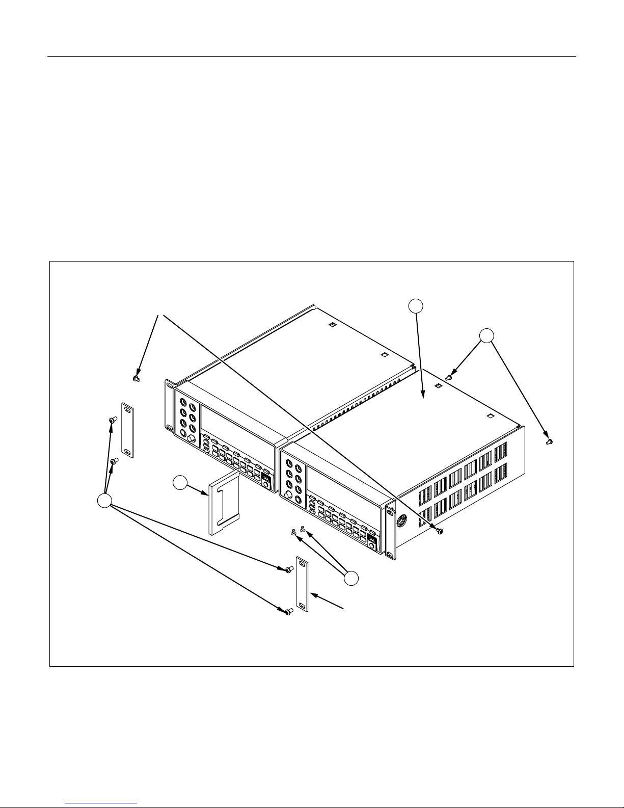
To install the Y8846D Rack Mount Kit, first follow
the steps 2, 3, and 4 listed under “Installing a Single
Rack Mount Kit” earlier in this document. Next,
perform the following steps to install the second
Meter:
1. Insert a second #6-32 x ½" flathead screw through
the hole in the back of the tray into the back of the
second Meter.
2. With the tray flat on a desk with the rack screw
ears toward you, place the second Meter so the
right side of the front frame is against the right
wall of the tray.
Dual Rack Mount
2x #8-32 x 1/2” Panhead
3. Insert the Dual Center Mount between the two
Meters, keeping the holes on the bottom.
4. Insert two #6-32 x ¼" screws through the bottom
of the tray and into the Dual Center Mount.
5. Install the assembled rack mount kit into a rack
using the two 1" wide small filler plates and four
#10-32 x ¾" Phillips rack screws.
6. Complete the installation by installing the Meter’s
power cord and other IO accessories through the
rear of the rack.
2
2x #6-32 x 1/2” Panhead
1
3
5
4x #10-32 x 3/4”
rack screw
Dual center
mount
4
2x #6-32 x 1/4” Flathead
2x Small filler plate
Figure 3. Dual Rack Mount
caw503f.emf
3
Page 4

Y8846S/Y8846D
Instruction Sheet
4
 Loading...