

Page 1
Instruction Manual
Model Y5020
Current Shunt
®
P/N 516591 September 1979
Page 2
Y5020
Page 3

Y5020
INTRODUCTION
The Model Y5020 is a precision, four-terminal, current
shunt designed for use in calibrating ac/dc current sources
in the range of 0 to 20 amps, do to 5 kHz. The shunt is
housed in a forced-air cooled, PTI (Portable Test
Instrument) case. This case is compatible with all
instruments in the Fluke PTI product line and can be
stacked with other PTI products to form a portable test
system.
Forced-air cooling is accomplished by a fan mounted on
the rear panel. Air is pulled in through the fan, passed over
the shunt, and exhausted through the rear panel. Power for
the fan is derived from the power line. Two voltage
configurations are available, 115 or 230V ac ±10%, 50 to
60 Hz.
Four front panel terminals provide electrical access to the
shunt; two are current input terminals and two are voltage
output (sense) terminals. When the shunt is connected into
a circuit and operating at its maximum current limit (20
amps), the input connections and the shunt present a
burden voltage of less than 0.25V dc.
SPECIFICATIONS
Specifications for the Y5020 Current Shunt are given in
Table 1.
1. Locate and pull the black latches on both sides of
the unit to their extended position.
2. Place the unit on top of the PTI stack with the front
panel toward the front of the stack.
3. When the unit is properly seated push both latches
to the in position. This will lock the Y5020 to the
stack.
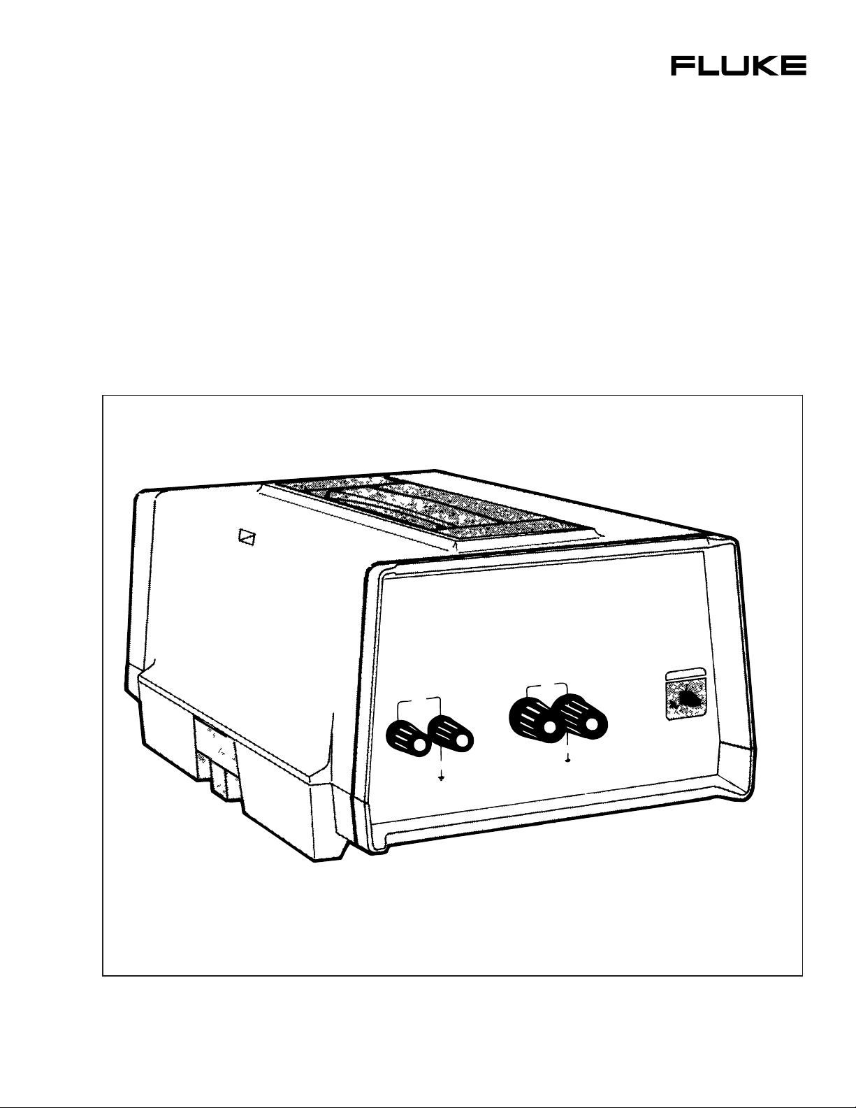
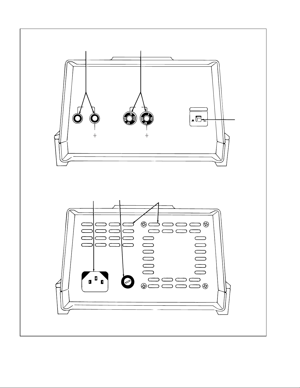
CONTROLS AND CONNECTORS
The front- and rear-panel controls and connectors on the
Y5020 are shown in Figure 1 and described in Table 2.
OPERATING NOTES
Input Power
Line power requirements for the Y5020 are specified on a
decal located on the bottom side of the unit. These include
line voltage requirements (115V or 230V ac ±10%, 50 to
60 Hz) and replacement fuse types. Input power is used
solely to power an internal cooling fan. A front panel
POWER switch allows the fan to be turned on and off.
Fuse Replacement
The Y5020 includes a fuse to protect the ac power line
from an accidental overload. If replacement is required, use
a 1/8 amp, 250 volt (AGC) fuse. Use the following
procedure to replace the fuse:
INSTALLAT ION
The Y5020 PTI case is designed to stack with other Fluke
instruments in the PTI product line. Use the following
procedure to stack the Y5020 with the other PTI
instruments.
Table 1. Y5020 Specifications
NOMINAL RESISTANCE
ACCURACY OF CALIBRATION VALUE
DC
DC to 1 kHz
1 kHz to 5 kHz
STABILITY OF CALIBRATION VALUE
MAXIMUM CURRENT
BURDEN VOLTAGE AT 20 AMPS
TEMPERATURE COEFFICIENT
POWER COEFFICIENT
POWER
1. Set the POWER switch to OFF and disconnect the
unit from line power.
2. Locate the fuse holder on the rear panel.
0.01Ω ±1%
±.01%
±.01%
±.025%
±.035%
(30 ppm per 6 months)
20A dc or rms ac
Less than 0.25V
≤0.001% per °C
≤0.005% at 20 amps
115V ac ±10% or 230V ac ±10%, 11 watts for cooling fan.
PROTECTION CLASS 3
Relates solely to insulating or grounding properties as
defined in IEC 348.
1
Page 4
Y5020
12
3
54
6
Figure 1. Controls and Connectors
2
Page 5

Table 2. Controls and Connectors
Y5020
REF
NO.
1 VOLTAGE OUTPUT Terminals A pair of binding posts that serve as the sense connections to the four-
2 CURRENT INPUT Terminals Two binding posts that serve as the current input connections to the
3 POWER Switch A push-push type switch used to switch the cooling fan on and off.
4 Input Power Connector A three-prong connector used to connect the instrument (via the power
5 Fuse Holder Holds the line power fuse for the cooling fan. The fuse provides ac input
6 Fan Intake and Exhaust Ports Cooling air for the shunt is pulled in through the rear-right port (intake)
3. Release the fuse by pressing in on the fuse cap
and turning it 1/8 of a turn counterclo ckwise. Use
a suitable screwdriver.
NAME FUNCTION
terminal shunt. The maximum sense voltage at 20 amps is 0.2 volts.
shunt. The maximum current rating for the shunt is 20 amps.
cord) to line power.
protection from overloads.
and exhausted through the rear-left port. The fan is located behind the
intake port.
voltage sense terminals and are not designed to carry any
measurement current. These sense terminals are connected
directly across the shunt.
CAUTION
To avoid fire hazard use only a 1/8 amp,
250 volt (AGC) fuse replacement.
4. Install the new fuse in the fuse cap and install
both in the fuse holder.
Forced-Air Cooling
CAUTION
To ensure the accuracy specifications
of the shunt, do not apply input current
to the Y5020 unless the cooling fan is
energized.
The Y5020 is equipped with an internal cooling fan to
ensure the accuracy and stability of the shunt over its
operating range (0 to 20 amps). The fan pulls the air in
through the rear panel, passes it over the shunt, and
exhausts it through the rear panel. Power for the fan is
derived from the ac power line. A front panel POWER
switch is used to turn the fan of f and on.
Four-Terminal Measurements
The Y5020 is a four-terminal current shunt. Two terminals
(CURRENT INPUT) are used to carry the current to be
measured. The other two (VOLTAGE OUTPUT) are
When current is passed through the shunt, the IR drop
developed across it can be read at the VOLTAGE
OUTPUT terminals using a high impedance voltmeter
(,>10 MW). Sinc e this vo ltage r ea di ng d o es no t i nc l ude the
IR drop of the current carrying conductors leading up to
the shunt, it provides an accurate indication of the current
flowing thro ugh the shunt.
Nominal Shunt Resistance
The current shunt used in the Y5020 has a nominal
resistance value of 0.01 ohms. This value was selected for
two reasons. First, the low resistance minimizes the voltage
drop (burden voltage) developed across the shunt. As a
result, the shunt has a negligible a ffect on the circuit into
which it is inserted. Second, the voltage drop across the
shunt relates directly to the current flowing through it. For
example, a current of 1 amp will produce a .O1 volt output.
This relationship is linear over the current range (0 to 20
amps).
Actual Shunt Value
The actual resistance value of the shunt is recorded in the
lower-right corner of the Y5020 front panel. This value is
traceable to the National Bureau of Standards, and must be
considered when required current accuracy is better than 1
percent.
3
Page 6

Y5020
Voltmeter Requirements
Accurate current measurements require the use of a
highimpedance (>10 MΩ) digital voltmeter to measure the
shunt voltage ap pearing at t he OUTP UT TERMIN ALS. In
addition, the voltmeter should have a voltage acc uracy of
at least ±0.01%, and be capable of resolving 10 µV on a
200 µV range. The use of a voltmeter that does not meet or
exceed these requirements will degrade the accuracy of the
current measurement.
Current Calculation
Precise current measurements require that the current value
be calculated using the SHUNT VALUE and the voltage
present at the VOLTAGE OUTPUT terminals; i.e., I =
VOLTAGE OUTPUT/SHUNT VALUE. For example:
SHUNT VALUE = .0100363
VOLTAGE OUTPUT = .050182
Current = .050182/.0100363 = 5.0000498 amps
OPERATION
With reference to the previous paragraphs use the
following procedure to operate the Y5020:
1. Connect the Y5020 to the line power and set the
POWER switch to ON.
2. Connect a suitable voltmeter (ac or dc) to the
VOLTAGE OUTPUT terminals, observe polarity.
3. Select the 200 mV range on the voltmeter.
4. Remove power from the circuit to be measured
and connect the Y5020 (as if it were an ammeter)
into the circuit using the CURRENT INPUT
terminals. Observe polarity.
5. Energize the circuit under test and derive the
measurement current using the SHUNT VALUE
and the voltmeter reading.
THEORY OF OPERATION
The Y5020 Current Shunt, as shown in Figure 2, is a
precision, four-terminal current shunt designed for use in
measuring ac/dc current in the range of 0 to 20 amps, dc to
5 kHz. Measurement current is connected at the
CURRENT INPUT terminals and passed through the shunt
resistor. The voltage drop developed across the shunt is
picked off at the shunt sense terminal and carried to the
front panel VOLTAGE OUTPUT terminals.
Current flowin g through the shunt is direc tly proportional
to the voltage present at the VOLTAGE OUTPUT
terminals, i.e. I = E/ R.
CURRENT INPUT
HI
CURRENT
SENSE
HI LO
VOLTAGE OUTPUT
Figure 2. Current Shunt
LO
01
W
MAINTENANCE
Access/Disassembly
To access the interior of the Y5020 remove the four screws
on the bottom of the unit and pull the top cover from the
bottom cover. All components are accessible with the top
cover removed.
The shunt is a plug-in assembly and may be pulled out for
inspection, repair and/or replacement. Do not bend the
shunt elements during the removal process.
Calibration
The Y5020 is not equipped with any calibration
adjustments. However, the SHUNT VALUE given on the
front panel should be verified every 180 days by a
calibration facility with NBS traceability.
LIST OF REPLACEABLE PARTS
A list of replaceable parts for the Y5020 is given in Table
3. Components are listed alphanumerically be assembly.
Electrical and mechanical components are listed by
reference designator. Each listed part is shown in an
accompanying illustration.
Parts may be ordered directly from the manufacturer by
using the ma nfacturer's part number or from the John Fluke
Mfg. Co., Inc. factory or authorized representative by using
the FLUKE Stock Number. If an ordered part has been
replaced by a new or improved part, the replacement will
be accompanied by an explanatory note and installation
instructions, if necessary.
4
Page 7

Y5020
To ensure prompt, efficient handling of your order, include
the following information:
1. Quantity.
2. FLUKE Stock Number.
3. Description.
4. Reference Designation.
Table 3. Y5020 Final Assembly
5. Printed Circuit Board Part Number and Revision
Letter.
6. Instrument Model and Serial Number.
SCHEMATIC DIAGRAM
A schematic diagram of the Y5020 is shown in Figure 4.
5
Page 8

Y5020
Table 3. Y5020 Final Assembly (cont)
6
Page 9

Y5020
MP16 (2)
SEE SHEET 2 OF 2
FOR DETAIL
H11 (2)
H2 (2)
H8 (2)
MP11 (2)
MP15
MP7
MP14 (4)
MP19 (2)
MP8 (2)
B1
MP13
H4
MP2
MP1
H8 (4)
Y5020-5001
(1 OF 2)
Figure 3. Y5020 Final Assembly
7
Page 10

Y5020
#18 GR/YEL
WIRE
H1
MP24
#22 WHITE WIRE
J1 (REF)
MP22 (REF)
MP10
R1
H6 (2)
TO B1 (WHITE)
#22 BLACK WIRE
XF1 (REF)
#22 BLACK WIRE
MP18
F1
DETAIL 1
S1
H5 (2)
MP4
H1
MP24
MP5
H6 (2)
A1
MP9
J3
J2
J5
J4
MP21
F1
MP22
XF1
H1 (2)
MP24 (2)
H7
J1
H1 (2)
(4)
SEE DETAIL 1
H10 (4)
H2 (4)
MP6 (2)
TO B1 (WHITE)
TO J1 (GRN/YEL)
(4)
MP20
H9 (4)
MP3
MP17
H3 (2)
H12 (2)
MP23 (2)
R1 (REF)
H6 (4)
H1 (2)
Y5020-5001
(2 OF 2)
Figure 3. Y5020 Final Assembly (cont)
8
Page 11

LINE
POWER
A1
F1
Y5020
FAN
S1
VOLT AGE
OUTPUT
CURRENT
INPUT
HI
LO
LO
HI
J2
J3
J4
P2
RED
BLK
R1
P3
P4
Figure 4. Y5020 Schematic Diagram
9
Page 12

Y5020
10
 Loading...