

Page 1

VT305
Gas Flow Analyzer
Users Manual
FBC-0034
January 2013, Rev. 1
© 2013 Fluke Corporation. All rights reserved. Specifications are subject to change without notice.
All product names are trademarks of their respective companies.
Page 2

Warranty and Product Support
Fluke Biomedical warrants this instrument against defects in materials and workmanship for one full year from the date of original purchase.
During the warranty period, we will repair or, at our option, replace at no charge a product that proves to be defective, provided you return
the product, shipping prepaid, to Fluke Biomedical. This warranty does not apply if the product has been damaged by accident or misuse or
as the result of service or modification by other than Fluke Biomedical. IN NO EVENT SHALL FLUKE BIOMEDICAL BE LIABLE FOR
CONSEQUENTIAL DAMAGES.
Only serialized products and their accessory items (those products and items bearing a distinct serial number tag) are covered under this
one-year warranty. PHYSICAL DAMAGE CAUSED BY MISUSE OR PHYSICAL ABUSE IS NOT COVERED UNDER THE WARRANTY.
Items such as cables and nonserialized modules are not covered under this warranty.
Recalibration of instruments is not covered under the warranty.
This warranty gives you specific legal rights, and you may also have other rights which vary from state to state, province to province, or
country to country. This warranty is limited to repairing the instrument to Fluke Biomedical’s specifications.
Page 3

Notices
All Rights Reserved
Copyright 2013, Fluke Biomedical. No part of this publication may be reproduced, transmitted, transcribed, stored in a retrieval system, or translated into any
language without the written permission of Fluke Biomedical.
Copyright Release
Fluke Biomedical agrees to a limited copyright release that allows you to reproduce manuals and other printed materials for use in service training programs and
other technical publications. If you would like other reproductions or distributions, submit a written request to Fluke Biomedical.
Unpacking and Inspection
Follow standard receiving practices upon receipt of the instrument. Check the shipping carton for damage. If damage is found, stop unpacking the instrument.
Notify the carrier and ask for an agent to be present while the instrument is unpacked. There are no special unpacking instructions, but be careful not to damage
the instrument when unpacking it. Inspect the instrument for physical damage such as bent or broken parts, dents, or scratches.
Technical Support
For application support or answers to technical questions, either email techservices@flukebiomedical.com or call 1-800- 850-4608 or 1-440-248-9300. In Europe,
email techsupport.emea@flukebiomedical.com or call +31-40-2965314.
Claims
Our routine method of shipment is via common carrier, FOB origin. Upon delivery, if physical damage is found, retain all packing materials in their original
condition and contact the carrier immediately to file a claim. If the instrument is delivered in good physical condition but does not operate within specifications, or
if there are any other problems not caused by shipping damage, please contact Fluke Biomedical or your local sales representative.
Returns and Repairs
Return Procedure
All items being returned (including all warranty-claim shipments) must be sent freight-prepaid to our factory location. When you return an instrument to Fluke
Biomedical, we recommend using United Parcel Service, Federal Express, or Air Parcel Post. We also recommend that you insure your shipment for its actual
replacement cost. Fluke Biomedical will not be responsible for lost shipments or instruments that are received in damaged condition due to improper packaging
or handling.
Use the original carton and packaging material for shipment. If they are not available, we recommend the following guide for repackaging:
Use a double–walled carton of sufficient strength for the weight being shipped.
Use heavy paper or cardboard to protect all instrument surfaces. Use nonabrasive material around all projecting parts.
Use at least four inches of tightly packed, industry-approved, shock-absorbent material around the instrument.
Page 4

Returns for partial refund/credit:
Every product returned for refund/credit must be accompanied by a Return Material Authorization (RMA) number, obtained from our Order Entry Group at 1440-498-2560.
Repair and calibration:
To find the nearest service center, go to www.flukebiomedical.com/service or
In the U.S.A.:
Cleveland Calibration Lab
Tel: 1-800-850-4608 x2564
Email: globalcal@flukebiomedical.com
Everett Calibration Lab
Tel: 1-888-99 FLUKE (1-888-993-5853)
Email: service.status@fluke.com
In Europe, Middle East, and Africa:
Eindhoven Calibration Lab
Tel: +31-40-2675300
Email: ServiceDesk@fluke.com
In Asia:
Everett Calibration Lab
Tel: +425-446-6945
Email: service.international@fluke.com
To ensure the accuracy of the Product is maintained at a high level, Fluke Biomedical recommends the product be calibrated at least once every
12 months. Calibration must be done by qualified personnel. Contact your local Fluke Biomedical representative for calibration.
Certification
This instrument was thoroughly tested and inspected. It was found to meet Fluke Biomedical’s manufacturing specifications when it was shipped from the
factory. Calibration measurements are traceable to the National Institute of Standards and Technology (NIST). Devices for which there are no NIST calibration
standards are measured against in-house performance standards using accepted test procedures.
WARNING
Unauthorized user modifications or application beyond the published specifications may result in electrical shock hazards or improper operation. Fluke
Biomedical will not be responsible for any injuries sustained due to unauthorized equipment modifications.
Restrictions and Liabilities
Page 5

Information in this document is subject to change and does not represent a commitment by Fluke Biomedical. Changes made to the information in
this document will be incorporated in new editions of the publication. No responsibility is assumed by Fluke Biomedical for the use or reliability of
software or equipment that is not supplied by Fluke Biomedical, or by its affiliated dealers.
Manufacturing Location
The VT305 Gas Flow Analyzer is manufactured in Switzerland for Fluke Biomedical, 6920 Seaway Blvd., Everett, WA, U.S.A.
Page 6

Page 7

Table of Contents
Title Page
Introduction .................................................................................................................... 1
Safety Information .......................................................................................................... 1
Responsibility and Warranty .......................................................................................... 3
Intended Use ................................................................................................................. 3
Software and Firmware versions ................................................................................... 4
System Requirements ................................................................................................... 4
Female Users ................................................................................................................ 4
Start Up ......................................................................................................................... 4
Power Supply ............................................................................................................ 5
Filter .......................................................................................................................... 5
Flow Channel ............................................................................................................ 6
Differential Pressure ................................................................................................. 6
High Pressure ........................................................................................................... 7
O2 Measurement Cell ................................................................................................ 7
Controls .................................................................................................................... 7
Electrical Interfaces ....................................................................................................... 9
Operation ....................................................................................................................... 10
How to Turn On and Turn Off the Product ................................................................ 10
The Start Screen ....................................................................................................... 10
Settings ..................................................................................................................... 11
i
Page 8

VT305
Users Manual
Numerical Values ...................................................................................................... 13
Graphical Values ....................................................................................................... 13
Filter .......................................................................................................................... 13
How to Save Data ..................................................................................................... 14
Zero-Point Calibration ............................................................................................... 14
Connect the Product ...................................................................................................... 15
Setup for Ventilator Measurements ........................................................................... 16
Setup for Precise Flow Measurements ..................................................................... 17
Setup for Dusty or Contaminated Gases ................................................................... 18
Setup for High Pressure Gases ................................................................................ 19
Measurement Data ........................................................................................................ 20
Store Measurement Data on the Micro-SD Card ...................................................... 20
How to Connect to the Computer .............................................................................. 20
How to Read the Data on the Computer ................................................................... 21
To Make an Excel File with Saved Values ................................................................ 22
Product Configuration .................................................................................................... 24
Values Configuration ................................................................................................. 26
Curves Configuration ................................................................................................ 27
Interface Configuration .............................................................................................. 28
Trigger Configuration ................................................................................................ 29
Miscellaneous Configuration ..................................................................................... 30
How to Setup an Ethernet Connection ...................................................................... 31
Default Ethernet Setup ......................................................................................... 31
Configured and DCHP Ethernet Setup ................................................................. 34
O2 Sensor ...................................................................................................................... 34
Activation .................................................................................................................. 34
Installation ................................................................................................................. 34
Oxygen Sensor Calibration – Air Only ....................................................................... 34
Oxygen Sensor Calibration – O2 and Air ................................................................... 35
Measure Respiratory Data ............................................................................................. 37
General ..................................................................................................................... 37
Connection to the Respiratory Apparatus ................................................................. 39
Standard Trigger Values ........................................................................................... 39
Baseflow ................................................................................................................... 39
ii
Page 9

Contents (continued)
Find the Correct Trigger Setting ................................................................................ 40
Flow Curve Downstream of the Y-Piece .............................................................. 40
Flow Curve Upstream of the Y-Piece ................................................................... 40
Pressure Curve Upstream of the Y-Piece ............................................................ 41
Special Cases ........................................................................................................... 41
Inspiration Volume Vti ............................................................................................... 41
Expiration Volume Vte .............................................................................................. 43
Care and Maintenance .................................................................................................. 44
Guidelines for Care and Maintenance ....................................................................... 44
Preventive Cleaning and Maintenance ..................................................................... 44
Accessories and Spare Parts ........................................................................................ 45
Ordering Address ...................................................................................................... 45
Disposal ......................................................................................................................... 46
Specifications ................................................................................................................ 47
Operation Principle of Flow Measurement ..................................................................... 51
Dynamic viscosity ..................................................................................................... 51
Density ...................................................................................................................... 51
Gas Standard ................................................................................................................ 52
Abbreviations and Glossary ........................................................................................... 52
Measured Values and Units ........................................................................................... 56
Conversion Factors ........................................................................................................ 58
iii
Page 10

VT305
Users Manual
iv
Page 11

List of Tables
Table Title Page
1. Symbols ................................................................................................................................ 3
2. Product Parts ........................................................................................................................ 4
3. Front-Panel Controls ............................................................................................................. 8
4. Electrical Interfaces .............................................................................................................. 10
5. Settings Screens ................................................................................................................... 11
6. Maintenance Tasks ............................................................................................................... 45
7. Standard Accessories ........................................................................................................... 46
8. Optional Accessories ............................................................................................................ 46
9. Measured Values and Units .................................................................................................. 56
10. Conversion Factors ............................................................................................................... 58
v
Page 12

VT305
Users Manual
vi
Page 13

List of Figures
Figure Title Page
1. Ports for Power Connection .................................................................................................. 5
2. Flow Channel ........................................................................................................................ 6
3. Differential Pressure Ports .................................................................................................... 6
4. High Pressure Ports .............................................................................................................. 7
5. O2 Cell .................................................................................................................................. 7
6. Electrical Interfaces .............................................................................................................. 9
7. Start-Up Screen .................................................................................................................... 10
8. Numerical Values Screens .................................................................................................... 13
9. Measured Curves Screens ................................................................................................... 13
10. Saving Data Screen .............................................................................................................. 14
11. Zero Calibration Screen ........................................................................................................ 14
12. Product to Breathing Apparatus Connections ....................................................................... 15
13. Ventilator Connections .......................................................................................................... 16
14. Precise Flow Measurement Connections .............................................................................. 17
15. Filter Use .............................................................................................................................. 18
16. High Pressure Connections .................................................................................................. 19
17. Mass Storage Message ........................................................................................................ 20
18. Micro-SD Card ...................................................................................................................... 20
19. Micro SD Card Files .............................................................................................................. 21
20. Report Data Files .................................................................................................................. 22
vii
Page 14

VT305
Users Manual
21. Formatted Excel File of Measurement Data .......................................................................... 23
22. Configuration Utility Web Page ............................................................................................. 25
23. Trigger Values Web Page ..................................................................................................... 26
24. Graphical Screen Configuration Web Page .......................................................................... 27
25. Create Configuration File Web Page .................................................................................... 29
26. Configure Triggers Screen .................................................................................................... 29
27. Miscellaneous Configuration Window ................................................................................... 30
28. Ethernet Connection Screen ................................................................................................. 31
29. Computer Ethernet Setup Windows ...................................................................................... 32
30. Ethernet IP Address Properties Form ................................................................................... 33
31. O2 Calibration - Apply Air ...................................................................................................... 34
32. O2 Calibration Successful Screen ......................................................................................... 35
33. O2 Calibration - Apply Oxygen .............................................................................................. 35
34. O2 Calibration - Apply Air ...................................................................................................... 35
35. O2 Calibration Successful Screen ......................................................................................... 36
36. Protective Cap Removal ....................................................................................................... 36
37. O2 Sensor Installation ........................................................................................................... 37
38. Breath Cycle ......................................................................................................................... 38
39. Downstream Flow Curve ....................................................................................................... 40
40. Inspiration Duct Upstream Curve .......................................................................................... 40
41. Upstream Pressure Curve..................................................................................................... 41
42. Inspiration Volume ................................................................................................................ 42
43. Expiration Volume ................................................................................................................. 43
44. Linear Flow Element ............................................................................................................. 51
viii
Page 15

Introduction
Warning
To prevent the possibility of personal injury,
read all safety information before you use the
Product.
This manual is applicable for the VT305 (the Product). It is
a compact, portable and easy-to-use measurement
instrument. The Product measures or calculates:
• Flow
• Volume
• Pressure differences
• High pressure
• Barometric pressure
• Oxygen
• Temperature of gas in the measurement chamber
• Breathing rate
• Inspiratory and expiratory time
• Ratios
• Ti/Tcyc
• Breathing volume
• Volumes per minute
• Peak flow
• Pressure
• Static Compliance (Cstat)
• Triggers (used to separate inspiration time from
expiratory time within each breath).
The Product measures and calibrates parameters on
breathing apparatuses.
Safety Information
A Warning identifies conditions and procedures that are
dangerous to the user. A Caution identifies conditions and
procedures that can cause damage to the Product or the
equipment under test.
1
Page 16

VT305
Users Manual
Warning
To prevent possible electrical shock, fire, or
personal injury:
• Read all safety Information before you use
the Product.
• Use the Product only as specified, or the
protection supplied by the Product can be
compromised.
• Do not connect the Product to a patient or
equipment connected to a patient. The
Product is intended for equipment analysis
only.
• Do not use the Product for diagnosis,
treatment, or other capacity where the
Product touches a patient.
• Remove the batteries if the Product is not
used for an extended period of time, or if
stored in temperatures above 50 °C. If the
batteries are not removed, battery leakage
can damage the Product.
• Recharge the batteries when the low
battery indicator shows to prevent
incorrect measurements.
• Do not use and disable the Product if it is
damaged.
• Do not use the Product if it operates
incorrectly.
• Examine the case before you use the
Product. Look for cracks or missing
plastic. Carefully look at the insulation
around the terminals.
• Use this Product indoors only.
• Carefully read all instructions.
• Do not touch voltages > 30 V ac rms, 42 V
ac peak, or 60 V dc.
2
Page 17

Gas Flow Analyzer
Responsibility and Warranty
Table 1 is a list of symbols used in this manual and on the
Product.
Table 1. Symbols
Symbol Definition
Risk of Danger. Important information. See
Manual.
Hazardous voltage
Conforms to relevant North American Safety
Standards.
Conforms to European Union directives
This product complies with the WEEE Directive
(2002/96/EC) marking requirements. The
affixed label indicates that you must not
discard this electrical/electronic product in
domestic household waste. Product Category:
With reference to the equipment types in the
WEEE Directive Annex I, this product is
classed as category 9 "Monitoring and Control
Instrumentation" product. Do not dispose of
this product as unsorted municipal waste. Go
to Fluke’s website for recycling information.
Responsibility and Warranty
The manufacturer assumes no responsibility or warranty,
nor accept liability if the user or third parties:
• Do not use the Product as intended.
• Violates the technical specifications.
• Changes the Product (through unauthorized
modifications, changes, etc.)
• Uses the Product with accessories other than those
shown in the related Product documentation.
Intended Use
This Product is intended to do tests on medical devices or
systems that deliver gas flow and pressure. This includes
ventilators and anesthesia systems.
The intended user is a trained biomedical equipment
technician who does preventative maintenance on medical
equipment. Users are associated with hospitals, clinics,
original equipment manufacturers, and independent
service companies. The end user is an individual, trained
in medical instrumentation technology.
This Product is intended to be used in a laboratory
environment, outside of patient care areas. It is not
intended for use on patients or on equipment connected to
patients. It is intended for over-the-counter use. This
Product is not intended to be used to calibrate medical
equipment.
3
Page 18
VT305
Users Manual
Software and Firmware versions
This manual is applicable for the Product with software
version 3.1 or higher and hardware version 1.0 or higher.
A product with different versions can operate differently
from this manual.
System Requirements
Your computer must have the minimum requirements
below:
• Microsoft Windows x86 or x64 (64-bit mode support for
IE only)
• 1.6 GHz or higher
• 512 Mb RAM
• Microsoft Windows, Vista, 7, 7 SP1, Windows Server
2008 SP2, Windows Server 2008 R2 SP1, Windows
Server 2003, XP SP2 and SP3
Female Users
This manual uses the male pronoun “he” for simplicity and
better understanding. This notwithstanding expressly
includes female users as well.
Start Up
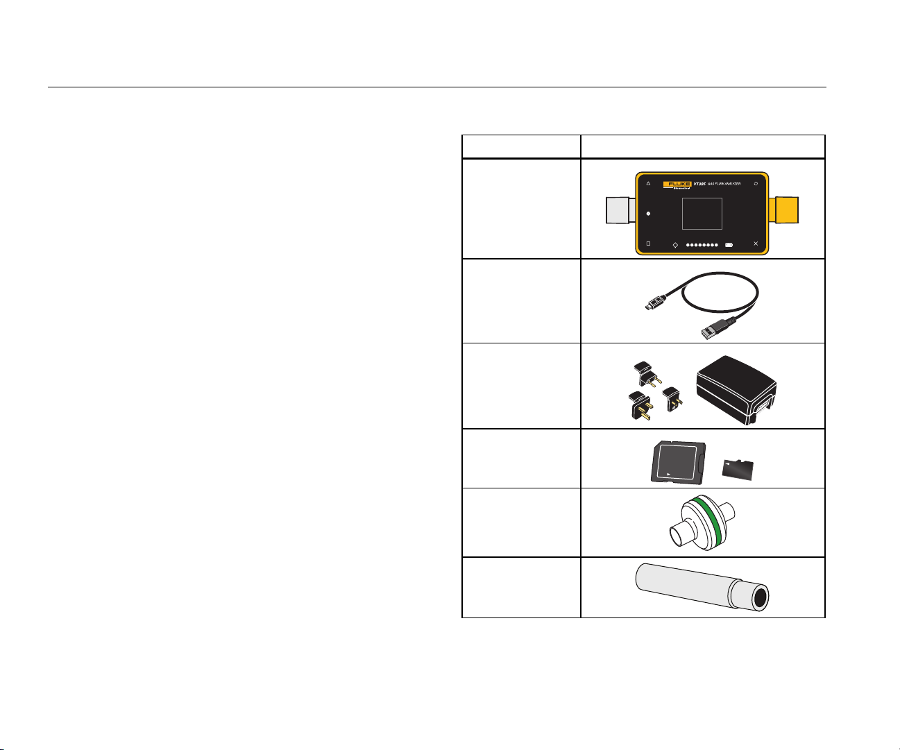
Table 2 is a list of parts included with the Product.
Table 2. Product Parts
Name Item
VT305
USB Cable
Power Supply
(power adapter)
Micro-SD 2GB
multi kit
Bacteria/Dust
Filter
Lock
4
Intlet Pipe
Page 19
Gas Flow Analyzer
Start Up
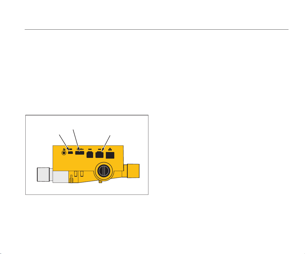
Power Supply
The Product can be operated from the power supply or the
built-in rechargeable battery.
Use the USB cable to connect the Product to a computer
or the included power supply. The USB port is shown in
Figure 1. You can power the Product through the analog,
USB, and CAN interfaces when you use the appropriate
optional adapters.
A battery symbol shows in the display when the battery
charges. The charge level of the battery is shown in the
battery display screen. A red LED shows in the left side of
the display when the battery is low.
Analog
Interface
USB Port
CAN interface
Connect the power adapter into a mains socket with a
voltage of 100 V ac to 240 V ac at 50 Hz or 60 Hz.
Caution
To prevent damage to the Product, make sure
the mains voltage is in the range specified on
the power adapter nameplate. Use the Product
only with the power adapter supplied with the
Product.
Filter
To prevent damage to the Product from dirt and particles
in the air, use the supplied filters for all flow
measurements. Use the filter to ensure laminar flow.
Laminar flow is necessary to make accurate flow
measurements.
Note
Particles in the air can clog the measurement
system, and cause an error message. Examine
the filter regularly.
Figure 1. Ports for Power Connection
gyo006.eps
5
Page 20
VT305
Users Manual
Flow Channel
The flow port can be used bidirectionally to measure flow,
volume, chamber gas temperature, oxygen, and pressure
in the flow channel. See the specifications for these
measurement ranges and accuracies. Figure 2 shows the
flow channel on the Product.
Flow
Channel
Figure 2. Flow Channel
Flow
Channel
gyo007.eps
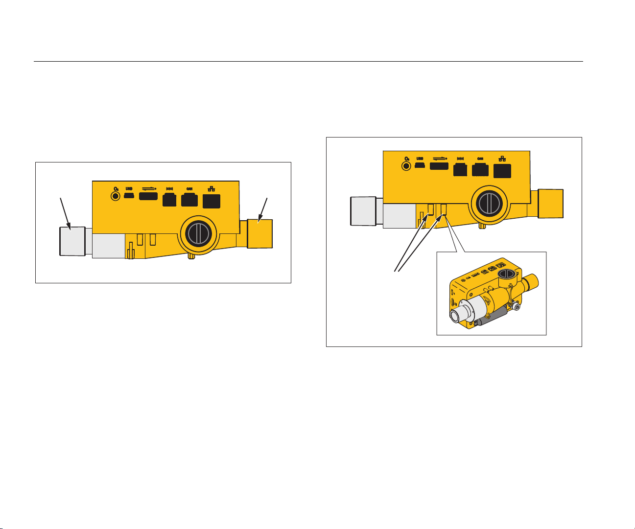
Differential Pressure
The differential pressure connections are used to measure
differential pressure. Figure 3 shows the differential
pressure connections.
Differential
Pressure
Figure 3. Differential Pressure Ports
gyo008.eps
6
Page 21
Gas Flow Analyzer
Start Up
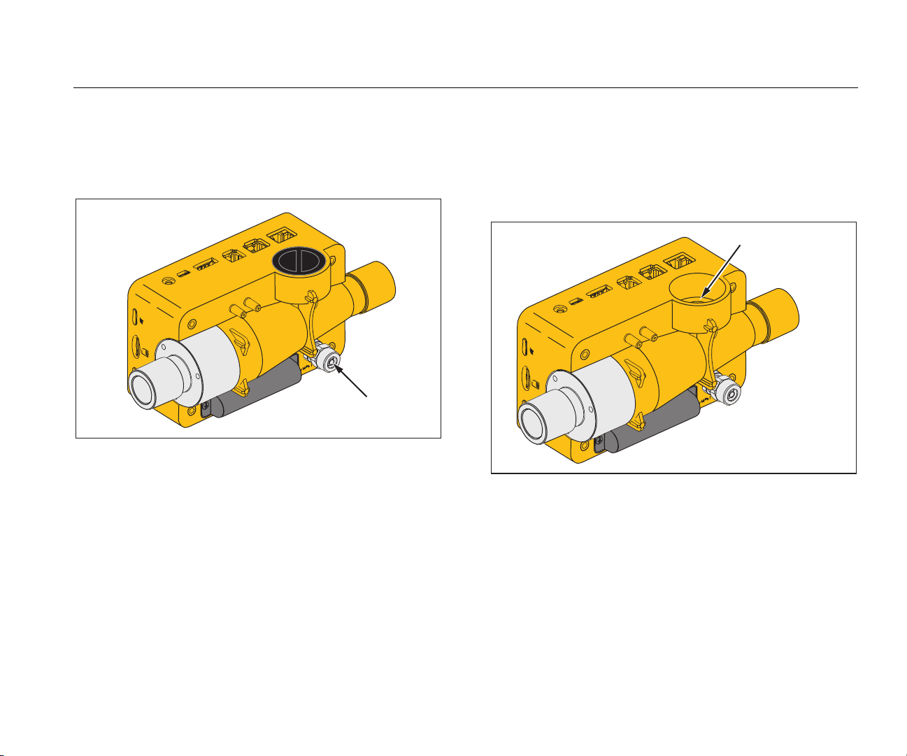
High Pressure
The high pressure port is used to measure pressure more
than 200 mbars. Figure 4 shows the high pressure port on
the Product.
High
Pressure
gyo009.eps
Figure 4. High Pressure Port
Note
For measurements to a maximum of 200 mbar,
Fluke Biomedical recommends you use the
differential pressure port. Accuracy is 100 times
higher.
O2 Measurement Cell
The Product has an interface for an O2 measurement cell.
See Figure 5. For more information, see the O
Sensor
2
section in this manual.
O2 – Measuring Cell
gyo010.eps
Figure 5. O2 Cell
Controls
Table 3 is a list of the front-panel controls.
Caution
To prevent damage to the high-pressure
sensor, do not measure pressure more than
15 bar.
7
Page 22
VT305
Users Manual
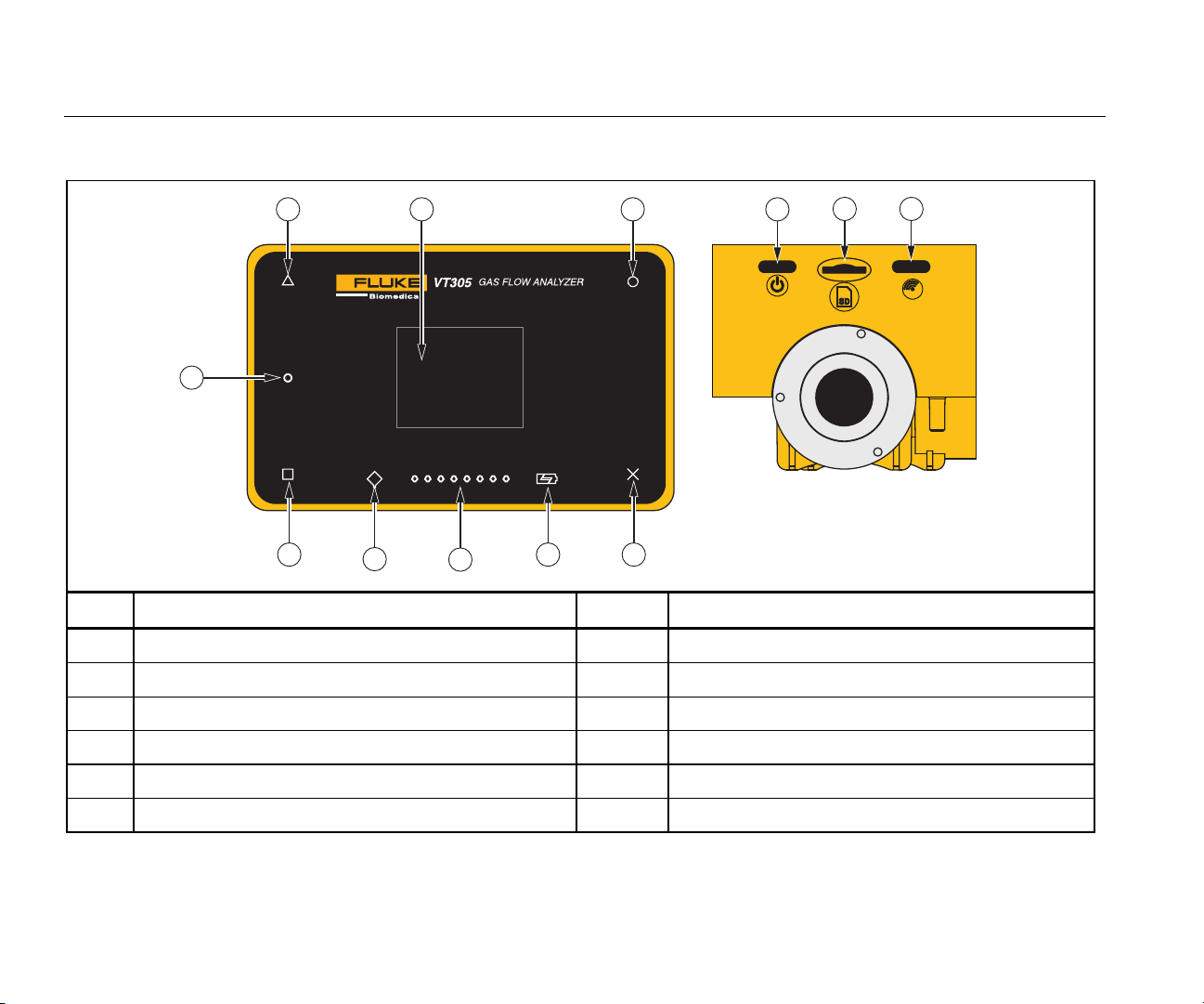
Table 3. Front-Panel Controls
1 311
12
2
10
9
8
4
5
6
7
gyo012.epx
Item Description Item Description
1 Display/Change measurement curves 7 Future use
2 Show/Change numerical measurement values 8 Battery on charge
3 Change settings/save data 9 Flow direction LEDs
4 Show menu/change menu/zero calibration 10 Function error LED
5 On/Off 11 Screen
6 Micro SD card slot 12 Low battery warning
8
Page 23
Gas Flow Analyzer
Electrical Interfaces
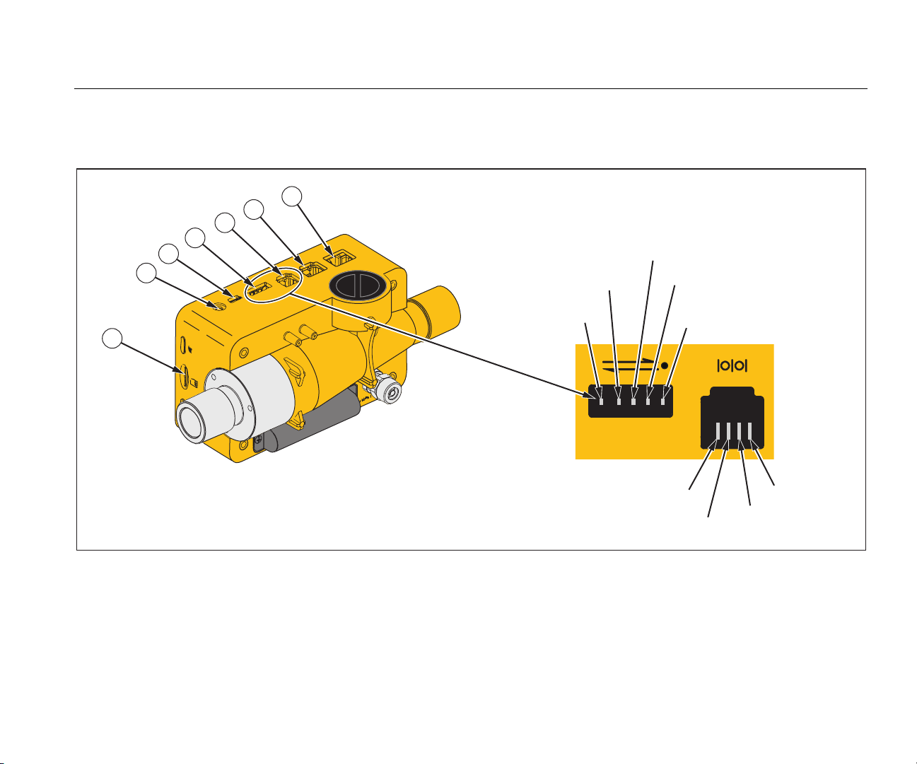
Electrical Interfaces
The Product has six electrical interfaces. Table 4 is a list of the electrical interfaces and references Figure 6.
7
6
5
4
3
2
V
IN
Trigger Input
Analog OUT 2
GND
1
TxD (output)
Analog OUT 1
GND
RxD (Input)
N.C.
gyo011.eps
Figure 6. Electrical Interfaces
9
Page 24

VT305
Users Manual
Table 4. Electrical Interfaces
Item Description
1
2 The O2 interface is used to connect the O2 sensor to the Product.
3
4
5 The RS-232 interface is used as a data interface. See the Specifications section for more data.
6 The CAN interface – future use.
7 The Ethernet interface is used to configure the Product and save the file to the SD card.
The Micro-SD card is used for software updates and Product configurations. Measurement data can be output
through the micro SD card. See the Measurement Data section.
The USB port is a data interface. It can also be used to operate with the mains power supply and to charge the
battery.
The Analog OUT port is used to output analog signals, connect to an external trigger, operate with the optional
mains power supply, and charge the battery of the Product. See the Specifications section for more data.
Operation
The sections that follow tell how to use the Product.
How to Turn On and Turn Off the Product
The Product is turned on and turned off when you push the
power button ().
The Start Screen
When the Product is turned on, the start-up screen in
Figure 7 shows in the display. After approximately
3 seconds the numerical measurement values show in the
display.
Settings
Push X on the front panel to show the information screen.
This shows the device data. Push X again to show more
menu items to make adjustments. Push O to change
Figure 7. Start-Up Screen
gyo076.eps
10
Page 25

Gas Flow Analyzer
Operation
individual settings. Table 5 is a list of screens that show in
the display.
Table 5. Settings Screens
Screen Description
Information
VT305
Owner:
Company:
Next Calib:
Last Calib:
Software:
Hardware:
Shows device data. You can
set Owner and Company data
fields with the browser-based
configurator. See the Product
Configuration section.
Battery
Shows the current charge of
the battery.
Table 5. Settings Screens (cont.)
Screen Description
Ethernet
Ethernet
Default
IP: 192.168.1.1
Subnet: 255.255.255..0
The Ethernet screen is used to
set the Ethernet communication
parameters.
Set Trigger
Trigger
Adult
Start: 60ms
Flow: >3.0 l/min
End: 60ms
Flow: >3.0 l/min
The Trigger events screen is
used to set when the Product
calculates volume, and
respiratory parameters. The
factory defaults show adult,
pediatric, and high frequency
trigger configuration. See the
Measure Key Respiratory Data
section.
Set Gas Standard
Standard
ATP
Amb. Temperature/Pressure
The Product calculates the
measured flow and volume
values for the set standard. See
the Gas Standard after the
Specifications section.
11
Page 26

VT305
Users Manual
Table 5. Settings Screens (cont.)
Screen Description
Set Gas Types
Gas Type
Air
Sets the gas type for the gas
to be measured. See the
Measurement Variables
section.
Set the X-Axis
X-Axis
0…2 sec
Sets the time base line for the
graphic/waveform displays (2,
4, 6, 8, and 10 seconds).
Humidity
Humidity
50.0%
Sets the percent (%) of relative
humidity in the gas flow (0 %
to 100 % in 10 % steps).
Table 5. Settings Screens (cont.)
Screen Description
O2 Calibration
O2 Calibr.
Used to calibrate the O
See the O
Sensor section.
2
cell.
2
12
Page 27

Gas Flow Analyzer
Operation
Numerical Values
Push on the display to show the numerical values screen
in the display. See Figure 8. You can change one, two,
four, or six numerical values on each screen. You
configure individual values and units through the web
browser-based configurator. See the Product
Configuration section.
ATP Air
ATP Air
0.0
Flow
l/min
Figure 8. Numerical Values Screens
The Product measures the temperature of the gas in the
measurement chamber inside the Product. This
temperature is not the same as the gas temperature that
enters the Product. The heat of the gas changes due to
the heat inside the Product.
The Product calculates static compliance (Cstat) with this
formula:
Cstat =
ATP Air
0.0
Flow
l/min
ATP Air
0.0
0.0
Flow
Flow
l/min
l/min
plateau – PEEP
P
gyo020.eps
V
t
When no plateau pressure is available, the formula has a
divisor of zero. The Product will show “---“ in the display
when this happens.
Graphical Values
Push Δ on the display to show the measured curves in the
display. See Figure 9. You can change one or two
measured curves each screen. You configure individual
values and units through the online application. See the
Product Configuration section.
Flow l/min
Flow l/min
Flow l/min
Flow l/min
gyo021.eps
Figure 9. Measured Curves Screens
Filter
The display update period is 500 ms or two times each
second. The acquisition time of new measurements is
5 ms to 8 ms. Without the filter, the latest measured value
is shown in the display when the screen updates. Because
each measurement has some noise, use the filter to
average the values equally for a specified period of time.
13
Page 28

VT305
Users Manual
The available filter selections are as follows:
• None (Display of the latest measured value without
thresholds)
• Low (Mean value over 240 ms)
• Medium (Mean value over 480 ms)
• High (Mean value over 960 ms)
The factory default for the filter is high.
You can change the filter selection in the browser-based
Product configuration tool. To learn more, see the Product
Configuration section.
How to Save Data
Push and hold O for 5 seconds to store data on the microSD card. The screen in Figure 10 shows in the display
while the Product saves the data. See the How to Read
Out Measurement Data section.
Data saved to
DATAxx.CSV
gyo022.eps
Figure 10. Saving Data Screen
Zero-Point Calibration
Push and hold X for 5 seconds to start the zero calibration
of the pressure and flow sensors. While the Product does
the calibration procedure, the screen in Figure 11 shows in
the display.
Zero- Calibration
Running
gyo023.eps
Figure 11. Zero Calibration Screen
It is important to do a zero calibration periodically to
remove off-sets in the flow measurement.
Caution
To make accurate measurements, do not apply
pressure to the Product when you do a zero
calibration. This caution is not shown in the
display when you use the X symbol.
It is very important to do the zero calibration while the
airway pressure transducer stabilizes and before a
measurement is made.
14
Page 29

Gas Flow Analyzer
Connect the Product
Connect the Product
Refer to Figure 12 when you do the subsequent steps.
1. Always use the dust filter.
2. Connect the tube system.
Note
Avoid tight bends, kinks, or dents in the tubing.
Good Setup
Flow
Direction
3. Connect the test lung.
4. Connect the breathing apparatus.
For more information on how to connect the breathing
apparatus, see the How to Measure Respiratory Data
section.
Figure 12. Product to Breathing Apparatus Connections
gyo053.eps
15
Page 30

VT305
Users Manual
Setup for Ventilator Measurements
To test and calibrate ventilators, use the inlet pipe between
the breathing circuit and the Product, as shown in
Figure 13. Use the filter to improve laminarity of the flow.
This improves measurement accuracy.
Breathing circuit Inlet Pipe Fluke VT305 Testlung
Positive flow direction
Figure 13. Ventilator Connections
gyo052.eps
16
Page 31

Gas Flow Analyzer
Connect the Product
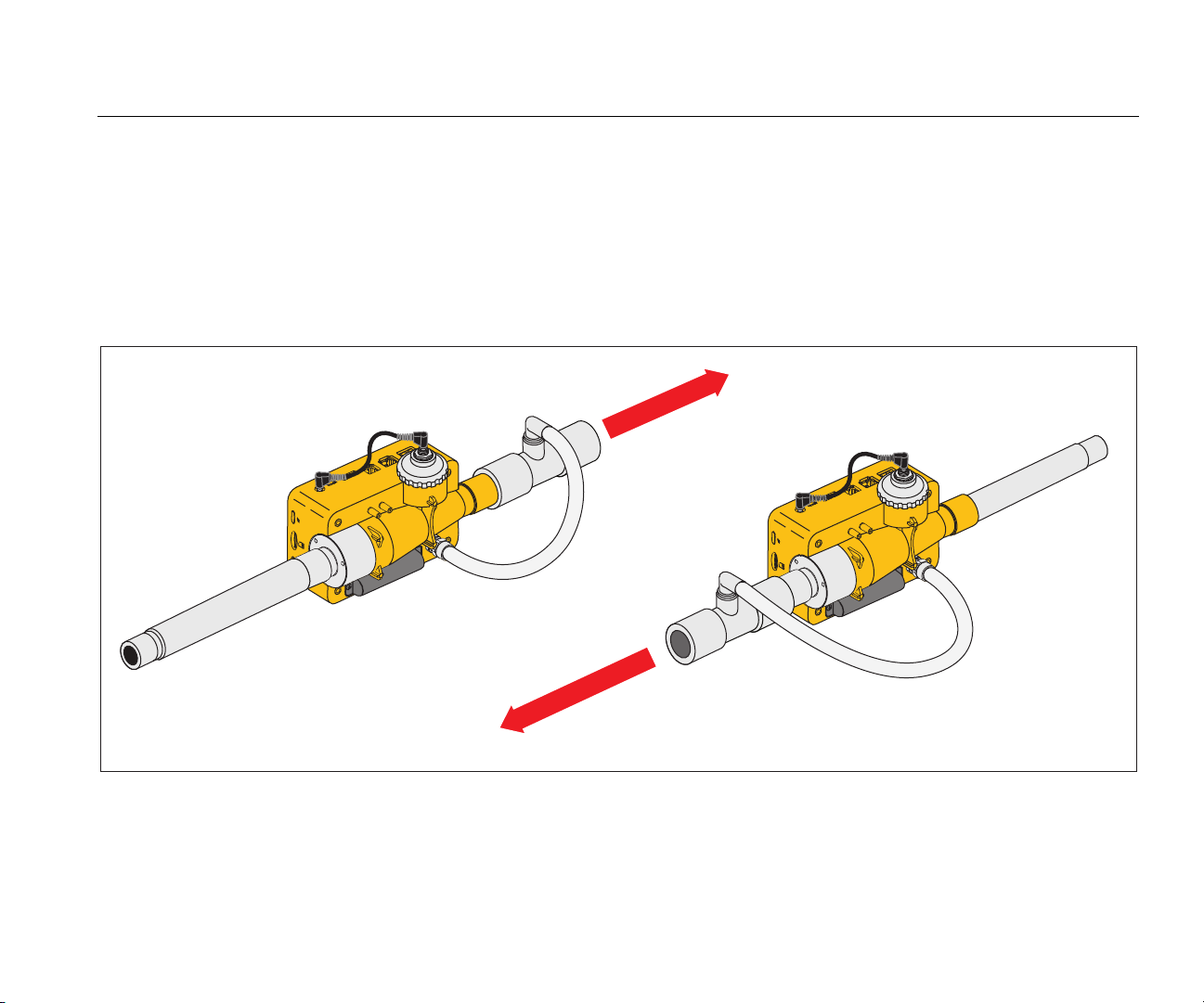
Setup for Precise Flow Measurements
Note
The measured gas must be free of oil, grease, and
dust. For best measurement results, set the trigger
to “adult.”
Positive Flow Direction
For precise flow measurements, put the inlet pipe and filter
on the Product as shown in Figure 14.
Negative Flow Direction
Figure 14. Precise Flow Measurement Connections
gyo049.eps
17
Page 32

VT305
Users Manual
Setup for Dusty or Contaminated Gases
When you use the Product to measure gas that contains
dust or other contaminants, use the filter as shown in
Figure 15.
Flow
Direction
Figure 15. Filter Use
Note
The gas must not contain oil or grease.
Distance tube from
filter to inlet Pipe:
minimum 1 meter.
gyo050.eps
18
Page 33
Gas Flow Analyzer
Connect the Product
Setup for High Pressure Gases
The Product automatically compensates for the gas
pressure in the flow channel up to 150 mbar. Use the high
pressure port as shown in Figure 16 for pressures greater
than 150 mbar.
Caution
To prevent damage to the Product, do not
apply more than 800 mbars to the airway
channel port of the Product.
In the flow channel, the Product adjusts for pressures to a
maximum of 150 mbars. When the high pressure port is
used, the Product adjusts for pressures up to a maximum
of 300 mbars.
Flow Direction
Flow Direction
Figure 16. High Pressure Connections
gyo051.eps
19
Page 34
VT305
Users Manual
Measurement Data
Product measurements can be exported on the micro-SD
card, analog out interface, or the RS-232 interface.
Store Measurement Data on the Micro-SD Card
Push and hold O for 5 seconds. This stores the
measurement data on the Micro-SD card. A message that
shows the filename that contains the measured data
shows in the display. The filename format is DataXX.csv.
See Figure 10.
There are two ways to get to the data on the Micro-SD
card. Use the USB port of the Product or put the Micro-SD
card into a computer.
To access data through the USB port, connect the USB
port of the Product to a computer.
Note
To communicate with the Product from a
computer, you must install a device driver. The
driver file “usb_cdc_ser.inf” is stored on the
Micro-SD card. Call or email technical support for
help.
When the Product senses USB communications, the
message in Figure 17 shows in this display. If you do not
make a choice in 5 seconds, the Product will not become a
USB mass storage device
Use as USB
mass storage?
YES NO
gyo063.eps
Figure 17. Mass Storage Message
When you use the Product as a USB mass storage device,
you cannot use the configuration tool to configure the
Product.
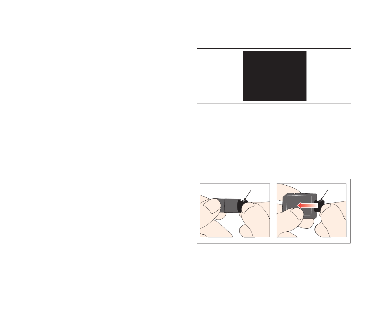
How to Connect to the Computer
Push the Micro-SD card to release it from the Product. You
can connect the Micro-SD card to your computer through a
USB port or SD-card socket. See Figure 18.
Micro-SD Card Micro-SD Card
gyo025.eps
Figure 18. Micro-SD Card
20
Page 35

Gas Flow Analyzer
Measurement Data
How to Read the Data on the Computer
Figure 19 shows the files and directory structure on the Micro-SD card used by the Product.
Figure 19. Micro SD Card Files
gyo073.jpg
21
Page 36

VT305
Users Manual
To Make an Excel File with Saved Values
1. Open the SetupReportFormatter.bat file. This file
installs ReportFormatter.xlsb in the Report/XLSTART
folder. This causes the ReportFormatter file to open
when Microsoft Excel is started. A list of files in the
Excel file open dialog box. See Figure 20. Double click
on a .csv file in the DATA folder to open it.
When you open a .csv file, a dialog box shows in the
computer display where you can set whether the
report data is formatted or not.
22
Figure 20. Report Data Files
gyo072.jpg
Page 37

Gas Flow Analyzer
Measurement Data
2. Click Yes to make a formatted file. The Product test
report like that shown in Figure 21 is made.
3. You can change the Excel file as necessary.
Note
Files on the Micro-SD card cannot be renamed.
Figure 21. Formatted Excel File of Measurement Data
gyo028.jpg
23
Page 38

VT305
Users Manual
Product Configuration
You can configure the Product through the Ethernet
interface. When a configuration parameter is changed, the
change will be made in the Product and saved on the
micro SD card immediately.
Note
You must install Microsoft Silverlight 5 on Internet
Explorer 7+, Safari 4+, Chrome 12+, or
Firefox 3.6+ to configure the Product through the
internet.
1. Insert a micro SD card that contains the necessary
files into the Product. The SD card must contain the
ClientBin folder that includes ConfigurationWeb.asp
file, the clientaccesspolicy.xml file, and the index.html
file.
Note
The micro SD card must be installed in the
Product if you want to save the configuration. If
you cannot find the micro SD card, talk to your
Fluke Biomedical distributor or call Fluke
Biomedical technical support. See Technical
Support in the front of this manual.
2. Connect the Ethernet port of the Product to a network
or directly to a computer.
The Default selection is the recommended method
when you connect the Product directly to a computer.
The Configured and DHCP-Client selection should
be used when you connect to an existing network.
See the How to Setup an Ethernet Connection section
for instructions to set an IP Address and subnet mask.
The browser-based configuration page in Figure 22
shows in the computer display when an Ethernet
connection is made.
5. To personalize the Product, type a name in the owner
field and a name in the company name field of the web
page.
6. In the upper-left corner of the web page, there are
main menu and submenu hyperlinks that you use to
navigate in the configuration tool.
7. To change Product configuration parameter values,
click on the configuration hyperlink. The configuration
page in Figure 23 shows in the computer display.
The submenu selections are VALUES, CURVES,
TRIGGERS, INTERFACE, and MISC. You click on these
submenu hyperlinks to open the configuration page that
will show the parameters for the selected parameter group.
3. Push X on the Product to show the Ethernet screen.
4. Push O to select one of the three internet connection
methods: Default, Configured, and DHCP-Client.
24
Page 39

Gas Flow Analyzer
Product Configuration
Figure 22. Configuration Utility Web Page
gyo030.jpg
25
Page 40

VT305
Users Manual
Values Configuration
gyo031.jpg
Figure 23. Trigger Values Web Page
The values configuration screen lets you set the value parameters in the Product. Click on the down arrow in each combo box
to show a list of parameters or values that you click on to set. To switch between Value 1, Value 2, and Value 3, click on the
grey banner of the window that shows the values you want to change. The Value 2 window is selected in Figure 23. To select
the Value 1 window shown on the left, click the grey Value 1 banner at the top of that window.
26
Page 41

Gas Flow Analyzer
Product Configuration
Curves Configuration
Change the displayed curves or associated units on the Product with the drop down combo boxes shown in Figure 24.
Figure 24. Graphical Screen Configuration Web Page
Note
The gas temperature shown on the display is the temperature of the gas in the measurement chamber and not the
temperature of the gas that flows into the Product. The temperature of the Product will change the temperature of the
gas that flows into the Product.
gyo032.jpg
27
Page 42

VT305
Users Manual
Interface Configuration
Use the Configure interfaces screen to setup the Ethernet connection and analog output channels. Use the drop-down
lists to set the IP configuration and analog outputs. See Figure 25.
28
Figure 25. Create Configuration File Web Page
gyo034.jpg
Page 43

Gas Flow Analyzer
Product Configuration
Trigger Configuration
Use the Configure triggers screen sown in Figure 26 to set one of the three preconfigured triggers.
Figure 26. Configure Triggers Screen
Click on the active button in one of the three windows to select the trigger you want to use in the Product. Some
parameters are set with the drop-down lists. Click on the Reset to Defaults button to set all trigger parameters to their
factory default values.
gyo064.jpg
29
Page 44

VT305
Users Manual
Miscellaneous Configuration
Change the miscellaneous parameters on the Product with the drop down combo boxes shown in Figure 27.
30
Figure 27. Miscellaneous Configuration Window
gyo054.jpg
Page 45

Gas Flow Analyzer
Product Configuration
How to Setup an Ethernet Connection
There are three Ethernet setup procedures: Default,
Configured, and DHCP-Client.
Default Ethernet Setup
The default setup is used when no network exists and you
connect the Product directly to the computer.
1. Use an Ethernet cable to connect the Ethernet port on
the computer to the Product.
2. Push X on the Product until the Ethernet screen shows
in the display. See Figure 28.
Ethernet
Default
IP: 192.168.1.1
Subnet: 255.255.255..0
Figure 28. Ethernet Connection Screen
3. If Default does not already show in the display, push
O until it does.
gyo062.eps
6. Click on Change adapter settings.
7. Double click on the Local Area Network. See
Figure 29.
8. Highlight Internet Protocol Version 4 (TCP/Pv4).
9. Click the Properties button. See Figure 30.
10. Set the IP Address to 192.168.1.2 (or any IP address
between 192.168.1.2 through 192.168.1.255) and the
subnet mask to 255.255.255.0.
11. Click the OK button.
12. Close all the windows you opened through the control
panel.
13. Open an Internet Browser.
14. In the address line, type the IP address shown in the
display of the Product and push Enter on the
computer keyboard.
The default configuration sets the IP Address of the
Product to 192.168.1.1 and the subnet mask to
255.255.255.0.
4. Open the Control Panel on the computer.
5. Click on Network and Internet in the control panel
window.
31
Page 46

VT305
Users Manual
32
Figure 29. Computer Ethernet Setup Windows
gyo074.eps
Page 47

Gas Flow Analyzer
Product Configuration
Figure 30. Ethernet IP Address Properties Form
gyo075.eps
33
Page 48

VT305
Users Manual
Configured and DCHP Ethernet Setup
The configured setup is used when a network that does
not have a DCHP server exists. The DCHP-Client setup is
used when you connect to networks that have a DCHP
server.
1. Use an Ethernet cable to connect the Ethernet port on
the Product to the network.
2. Push X on the Product until the Ethernet Configured
or Ethernet DCHP – Client screen shows in the
Product display.
3. Open an Internet Browser.
4. In the address line, type the IP address shown in the
display of the Product and push Enter on the
computer keyboard.
Note
There can only be one connection to the
configuration tool for a single Product. With the
configuration tool open, the Product cannot be
configured from another computer.
The configuration tool will download to the computer and
establish a connection.
O2 Sensor
Activation
The Product has an interface for an oxygen sensor. The
oxygen sensor must be calibrated with air and 100 % O
.
2
Installation
A kit that has the oxygen sensor and connection cable
comes with the oxygen option.
Remove the protective cap (rubber stopper) from the
sensor.
Oxygen Sensor Calibration – Air Only
Note
Fluke Biomedical does not recommend you
calibrate the oxygen sensor with air.
To calibrate the oxygen sensor with air:
1. Push X on the front panel until O2 Calibration with Air
shows in the display.
2. Push O to start the calibration process.
3. Apply 25 l/min of air to the flow channel of the Product
when the instruction shows in the display. See
Figure 31.
O2 Calibration
Air
Apply 25 I/min (0)
Press o to start
Figure 31. O2 Calibration - Apply Air
gyo066.eps
34
4. Push O to continue.
Page 49

Gas Flow Analyzer
O2 Sensor
Note
To stop the calibration procedure, push X.
Air calibration starts and will take 114 seconds to
complete. Under no circumstances interrupt the flow of
air through the flow channel. The screen in Figure 32
shows in the display when the calibration is done.
O2 Calibration
Air successful
Press any key to exit
gyo067.eps
Figure 32. O2 Calibration Successful Screen
Oxygen Sensor Calibration – O2 and Air
To calibrate the oxygen sensor with air and oxygen:
1. Push X on the front panel until O2 Calibration with O2
and Air shows on the display.
2. Push O to start the calibration process.
3. Apply 25 l/min of 100 % oxygen to the flow channel of
the Product when the instruction shows in the display.
See Figure 33.
O2 Calibration
100% O2
Apply 25 I/min (0)
Press o to contiue
gyo070.eps
Figure 33. O2 Calibration - Apply Oxygen
4. Push O to continue.
Note
To stop the calibration procedure, push X.
Oxygen calibration starts and will take 114 seconds to
complete. Under no circumstances interrupt the flow of
gas through the flow channel.
5. Apply 25 l/min of air to the flow channel of the Product
when the instruction shows in the display. See
Figure 31.
O2 Calibration
Air
Apply 25 I/min (0)
Press o to start
gyo066.eps
Figure 34. O2 Calibration - Apply Air
Air calibration starts and will take 114 seconds to
complete. Under no circumstances interrupt the flow of
air through the flow channel.
35
Page 50

VT305
Users Manual
The screen in Figure 35 shows in the display when the
calibration is done.
O2 Calibration
O2 and Air
successful
Press any key to exit
Figure 35. O2 Calibration Successful Screen
gyo069.eps
gyo035.eps
Figure 36. Protective Cap Removal
Turn the O
sensor clockwise to attach it to the Product.
2
Use the sensor cable to connect it to the Product. See
Figure 37.
36
Page 51

Gas Flow Analyzer
Measure Respiratory Data
Measure Respiratory Data
General
To measure key respiratory data, the Product must read
out a breath cycle from the measured pressure and/or flow
chart curves. This is controlled through the triggers shown
in Figure 38.
Figure 37. O2 Sensor Installation
gyo036.eps
37
Page 52

VT305
Users Manual
V
Breath Cycle
ExpirationInspiration
S
Start Trigger
V
0
End Trigger
Figure 38. Breath Cycle
It is very important to set the start and stop triggers
correctly. These triggers significantly influence the
measurement results because they trigger the breath
cycles. Make sure these triggers are set correctly before
you start respiratory data measurement.
E
S
Note
The start trigger is interpreted as the start of the
inspiration phase. The stop trigger is interpreted
as the end of the inspiration phase and the start of
the expiration phase. The expiration continues
until the subsequent start trigger.
gyo037.eps
38
Page 53

Gas Flow Analyzer
Measure Respiratory Data
Connection to the Respiratory Apparatus
There are three different methods to connect the Product
to the respiratory apparatus:
• Downstream of the Y-piece
Fluke VT305
Ventilator
• In the inspiration duct upstream of the Y-piece
Fluke VT305
Ventilator
• In the expiration duct upstream of the Y-piece
Test Lung
gyo038.eps
Test Lung
gyo039.eps
Test Lung
Ventilator
Fluke VT305
gyo040.eps
Standard Trigger Values
Because the Product can measure flow in each direction, it
makes sense to use the first connection method. In this
measurement setup, flow is usually chosen as the trigger
value. Flow triggers are stored as standard values in the
device and can be reset when necessary. The standard
trigger values for the flow trigger for adult breathing, for
example, are:
Starttrigger: Flow > 3 l/min
Endtrigger: Flow < -3 l/min
With the second and third connection methods, pressure is
usually chosen as the trigger signal. In this case the
standard values are as follows:
Starttrigger: Pressure > 1 mbar
Endtrigger: Pressure < 1 mbar
Baseflow
The base flow is the constant flow that must be ignored
when you calculate volume. If there is an identified
leakage in the system, like a constant discharge of 3 l/min
39
Page 54

VT305
Users Manual
of air, the 3 l/min is not counted as inspiration volume.
When you type in:
Base flow: on 3.0 l/min
the volume calculation in our example could be corrected.
Type the base flow parameter value in the configurator
base flow section.
Find the Correct Trigger Setting
When you set a trigger for the first time, it is important to
know the curve of the signal for the trigger (flow or
pressure). Here are some examples that also show
possible problems.
Flow Curve Downstream of the Y-Piece
Figure 39 is an example of a flow curve downstream of the
Y-piece. The standard triggers (> 3 l/min/< –3 l/min) can
be used without a problem.
Note
In such situations it is important to keep in mind that the
trigger is significantly higher than the noise of the base
line. Incorrect triggers can be released.
Flow Curve Upstream of the Y-Piece
The curve in Figure 40 shows the flow curve in the
inspiration duct upstream of the Y-piece. The first two
circles show the triggers that must be used here. The top
figure shows a small incorrect signal at the measurement
point after the inspiration. This is caused by switching the
valves. This results in faulty triggering.
Faulty triggering!
40
Figure 39. Downstream Flow Curve
gyo041.jpg
Time [S]
Figure 40. Inspiration Duct Upstream Curve
gyo042.eps
Page 55

Gas Flow Analyzer
Measure Respiratory Data
Note
Flow cannot be used here as a trigger. The
pressure curve must be used.
Pressure Curve Upstream of the Y-Piece
For the pressure curve shown in Figure 41, the standard
triggers can be used: (> 1 mbar / < 1 mbar).
gyo043.jpg
Figure 41. Upstream Pressure Curve
Note
The trigger is significantly higher than the noise of
the base line. If not, the trigger value must be
increased.
Special Cases
In measurement technology there can always be a
deviation from the standard variants to get a more
accurate result. You can get very accurate results with the
settings shown in this manual, which is better than the
accuracy of all respiratory equipment.
Measurement errors inherent in the overall system occur in
the respiratory apparatus and in the Product. The values
shown in the display can be different because not the
same thing was measured and compared.
Inspiration Volume Vti
If the breath curve shows a plateau or a break, a tiny flow
can be measured during this time. A lot of breathing
equipment does not include these tiny flows when they
calculate Vti. You can match this behavior in the Product
when you use the trigger values that follow:
In Figure 42, S shows the start trigger and E the end
trigger.
41
Page 56

VT305
Users Manual
Start and
End Trigger
V
V
Breath Cycle
Inspiration
Expiration
Vti
E
0
S S
t
gyo044.eps
Figure 42. Inspiration Volume
42
Page 57

Gas Flow Analyzer
Measure Respiratory Data
Expiration Volume Vte
Figure 43 shows the optimal trigger values to measure Vte.
Breath Cycle
Inspiration
Start Trigger
End Trigger
V
S
V
0
Figure 43. Expiration Volume
The start trigger must be set to S and the end trigger to E.
Vte
E
Expiration
S
t
gyo045.eps
43
Page 58

VT305
Users Manual
Care and Maintenance
Warning
To prevent possible electrical shock, fire, or
personal injury:
• Batteries contain hazardous chemicals that
can cause burns or explode. If exposure to
chemicals occurs, clean with water and get
medical aid.
• Do not disassemble the battery.
• Do not disassemble or crush battery cells
and battery packs.
• Do not put battery cells and battery packs
near heat or fire. Do not put in sunlight.
• Do not operate the Product with covers
removed or the case open. Hazardous
voltage exposure is possible.
• Use only specified replacement parts.
• Have an approved technician repair the
Product.
For safe operation and maintenance of the
product:
• Keep cells and battery packs clean and
dry. Clean dirty connectors with a dry,
clean cloth.
• Do not keep cells or batteries in a
container where the terminals can be
shorted.
Guidelines for Care and Maintenance
For safe and reliable operation of the Product, follow these
maintenance guidelines. Use only components
recommended by the manufacturer.
Note
You must use the guidelines and maintenance
instructions supplied by the manufacturer.
Preventive Cleaning and Maintenance
Note
The maintenance tasks shown below must only be
done by personnel that know the Product. All other
repairs must be done by approved personnel.
To keep the Product accurate and reliable in the long term,
follow the maintenance tasks in Table 6 on a regular basis:
• Repair the Product before use if the battery
leaks.
• Do not short the battery terminals together.
44
Page 59

Gas Flow Analyzer
Accessories and Spare Parts
Table 6. Maintenance Tasks
Interval Task
While in
operation
4 weeks Examine the filter for contamination.
12 Months Factory calibration to make sure the
Use the supplied filter.
To do this, connect the filter inlet
and outlet to the differential
pressure connection with two Tpieces. Measure the pressure loss
across the filter with this
connection. The pressure loss for a
flow of 60 l/min cannot be more
than 2 mbar. If the pressure is more
than 2 mbar, the filter must be
replaced.
Product gives reliable
measurements.
Accessories and Spare Parts
Ordering Address
Fluke Biomedical
6045 Cochran Rd.
Cleveland, OH 44139
USA
Telephone: +1 440-248-9300
Toll-free: (800) 850-4608
Fax: +1 440-349-2307
E-Mail: sales@flukebiomedical.com
Or
Fluke Biomedical Europe
Science Park Eindhoven 5110
5692EC Son
The Netherlands
Telephone: +31 40 267 5436
Fax: +31 40 267 5436
E-Mail: ordersupport.emea@flukebiomedical.com
45
Page 60

VT305
Users Manual
Table 7. Standard Accessories
Item Part No.
O2 SENSOR ASSEMBLY 4281611
ACCULUNG II PORTABLE PRECISION
TEST LUNG
PROTECTION FILTER 4294528
ADAPTER SET 4294537
O2 SNR CABLE 4296104
O2 HIGH PRESSURE ADAPTER 4294543
PWR ADAPTER SET 4308219
SD CARD 2GB 4296162
INLET PIPE 4296170
CARRY CASE 4296181
Table 8. Optional Accessories
Item Part No.
AIR HIGH PRESSURE ADAPTER 4294555
4281291
Disposal
The manufacturer is responsible for disposal of this
Product. The device must be shipped (free and with duty
paid) to the manufacturer for disposal.
• A licensed private or public collection company can
take this Product for disposal.
• The Product can be disassembled into individual
components and then recycled or discarded in the
correct manner.
• If disposal is done by the manufacturer, the regulations
for disposal are contingent on the country and are
subject to its laws and legal requirements. You can get
the applicable rules and regulations from the
responsible authority.
In this regard, the Product is to be recycled or discarded:
• Without effect on human health.
• Without the use of procedures or methods that cause
damage to the environment (water, air, soil, flora, and
fauna).
ANSUR VT PLUG-IN LICENSE 4296065
For more accessories and spare parts, go to
www.FlukeBiomedical.com
46
Page 61

Gas Flow Analyzer
Specifications
Specifications
Display ................................................................... 26 mm x 33 mm
Real time curves ................................................... Flow, Pressure, Volume, temperature of gas inside the measurement chamber, oxygen, respiratory
Interfaces ............................................................... RS-232, USB, Ethernet, CAN, Analog Out, TTL
Temperature (gas in measurement chamber)
Operating ............................................................ 15 °C to 40 °C (59 °F to 104 °F)
Storage ............................................................... -10 °C to 60 °C
Relative humidity
Operating ............................................................ 10 % to 90 % RH
Storage/Transportation ....................................... 5 % to 95 % RH
Ambient pressure ................................................. 500 mbar to 1150 mbar
Power
AC adapter
Voltage input ................................................... 100 V ac to 240 V ac, 50 Hz to 60 Hz
Supply voltage ................................................ 5 V dc
Power consumption ........................................ 2.5 W to 6 W
Battery
Battery life ....................................................... 4 hours. Operation time will be reached in standalone operation (without use of interfaces)
Recharge time ................................................ 5 to 8 hours (varies with port used)
Dimensions (W x L x H) ........................................ 16.5 cm x 10.8 cm x 6.4 cm (6.5 in x 4.25 in x2.5 in)
Weight .................................................................... 0.4 kg
Safety ..................................................................... IEC 61010-1: Pollution Degree 2
Electromagnetic Environment ............................. IEC 61326-1: Portable
Calibration interval ............................................... annually
Memory Card ......................................................... yes
Data Interfaces
Analog port
Analog Output 1 .............................................. 0 Vdc to 5 Vdc ±1.8 %, load ≥5 kΩ
Analog Output 2 .............................................. 0 Vdc to 5 Vdc ±1.8 %, load ≥5 kΩ
parameters
47
Page 62

VT305
Users Manual
Trigger Input ................................................... 5 Vdc to 24 Vdc
V
IN .................................................................. 9 Vdc to 29 Vdc
RS-232 Port
Baud Rate ........................................................... 19200, 8 bits, no Parity, 1 stop bit
Measurement Variables
Air and N2
Flow Measurements
Range ......................................................... ±300 sl/min
Accuracy ..................................................... ±1.9 %* or ±0.1 l/min
Ambient pressure compensated ..................... yes
Temperature compensated ............................ yes
O2/Air Mixtures
Flow Measurements
Range ......................................................... ±300 sl/min
Accuracy ..................................................... ±1.9 %* or ±0.1 l/min
Ambient pressure compensated ..................... yes
Temperature compensated ............................ yes
CO2
Flow Measurements
Range ......................................................... ±140 sl/min
Accuracy ..................................................... ±3.0 %* or ±0.1 l/min
Ambient pressure compensation accuracy ..... 25 °C to 30 °C
Temperature compensated ............................ yes
Channel pressure compensation accuracy .... -50 to +600 mbar
Heliox (21 % O2/ 79 % He)
Flow Measurements
Range ......................................................... ±300 sl/min
Accuracy ..................................................... ±4.0 %* or ±0.3 l/min
Ambient pressure compensation accuracy ..... 25 °C to 30 °C
Temperature compensated ............................ yes
48
Page 63

Gas Flow Analyzer
Specifications
N2O/O2 Mixtures
Flow Measurements
Range ......................................................... ±80 sl/min
Accuracy ..................................................... ±4.0 %* or ±0.3 l/min
Ambient pressure compensation accuracy ..... 25 °C to 30 °C
Temperature compensated ............................ yes
Pressure
High
Range ......................................................... 0 to 10 bar
Accuracy ..................................................... ±1 %* or ±10 mbar**
Difference
Range ......................................................... ±200 mbar
Accuracy ..................................................... ±0.75 %* or ±0.1 mbar
In the flow channel
Range ......................................................... -50 to 150 mbar
Accuracy ..................................................... ±0.75 %* or ±0.1 mbar
Barometer
Range ......................................................... 500 to 1150 mbar
Accuracy ..................................................... ±1.0 %* or ±5.0 mbar
Variables
Flow ................................................................ l/min, l/s, cfm, ml/min, ml/s
Pressure ......................................................... bar, mbar, cmH
Oxygen concentration (pressure compensated ≤150 mbar)
Range ......................................................... 0 % to 100 %
Accuracy ..................................................... ±1 % O
2
Gas Temperature
Range ......................................................... 0 °C to 50 °C
Accuracy ..................................................... ±1.75 %* or ±0.5 °C
Type of gas ..................................................... Air, Air/O
Gas Standard ................................................. ATP, ATPD, ATPS, AP21, STP, STPH, BTPS, BTPD, 0/1013, 20/981, 15/1013, 25/991, 20/1013
O, inH2O, Torr, inHg, hPa, kPa, mmHg, PSI
2
**
, N2O/O2, Heliox (21 % O2), He/O2, N2, CO
2
2
49
Page 64

VT305
Users Manual
Respiratory Parameters
Breathing Rate (BR/min)
Range ......................................................... 1 bpm to 1000 bpm
Accuracy ..................................................... ±1 bpm or ±2.5 % **
Time (Ti, Te)
Range ......................................................... 0.05 s to 60 s
Accuracy ..................................................... ±0.02 s
Ratio (I:E)
Range ......................................................... 1:300 to 300:1
Accuracy ..................................................... ±2.5 %*
Ratio (Ti/Tcyc)
Range ......................................................... 0 % to 100 %
Accuracy ..................................................... ±5 %*
Breathing Volume (Vti, Vte)
Range ......................................................... ±10 l
Accuracy ..................................................... ±2 %* or ±20 ml
Volume per minute (Vi, Ve)
Range ......................................................... 0 l/min to 300 l/min
Accuracy ..................................................... ±2.5 %*
Peakflow
Range ......................................................... ±300 l/min
Accuracy ..................................................... ±1.9 %* or ±0.1 l/min
Pressure (Ppeak, Pmean, PEEP, Pplateau)
Range ......................................................... 0 mbar to 150 mbar
Accuracy ..................................................... ±0.75 %* or ±0.1 l/min
Compliance (Cstat)
Range ......................................................... 0 ml/mbar to 1000 ml/mbar
Accuracy ..................................................... ±3 %* or ±1 ml/mbar
Trigger Range (Adult, Pediatric, HFO) ........... Flow and volume (from default settings and adjustable levels) the greater tolerance is valid
* Tolerance related to the measured value.
** Absolute tolerance.
*** sl/min is based on ambient conditions of 0° C and 1013 mbar (DIN 1343)
50
Page 65
Gas Flow Analyzer
Operation Principle of Flow Measurement
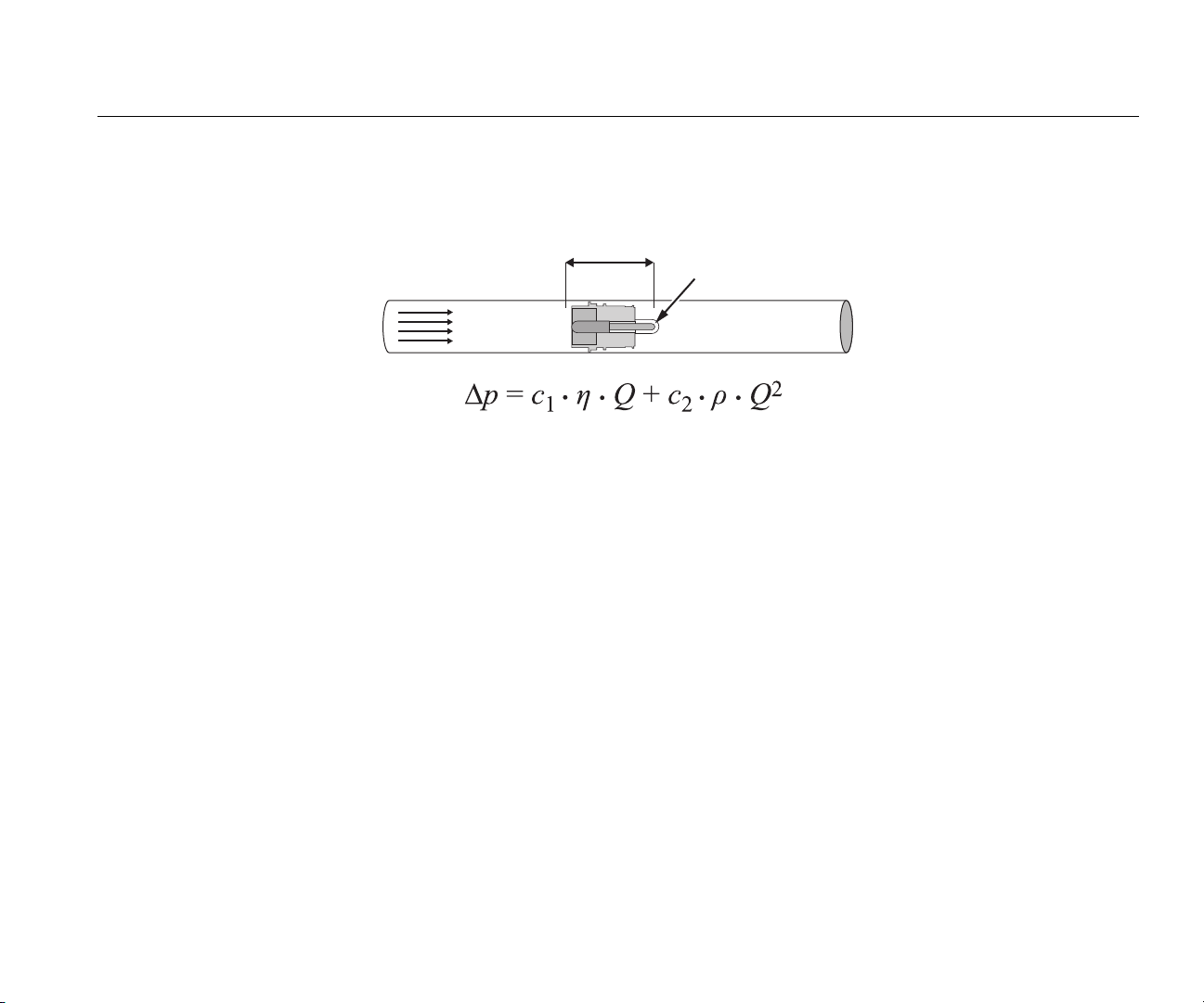
Operation Principle of Flow Measurement
A differential pressure measurement is used to find the flow in the flow channel. To make the pressure difference, a linear flow element is used as a flow
resistance. See Figure 44.
Pressure Difference ∆p
Linear flow element
Gas Flow Q
Figure 44. Linear Flow Element
η: dynamic viscosity of the gas (Pa s)
p: Gas density (kg/m
c1, c2: device-specific constants (channel geometry)
3
)
Dynamic viscosity
• The viscosity of a medium, is its resistance to flow and tear off of the flow.
• The viscosity is strongly contingent on the temperature.
• The viscosity of the medium is slightly dependent on pressure and humidity of the medium.
Density
• Density is the unit of mass per unit volume of the medium.
• Density is strongly contingent on the pressure and temperature.
The influence of environmental conditions is the reason why the flow is occasionally transformed to standard conditions.
gyo046.eps
51
Page 66

VT305
Users Manual
Gas Standard
Gas Standard Temperature Pressure
Ambient Temperature and Pressure (ATP) Current Gas temperature Current ambient pressure
Ambient Temperature and Pressure Dry (ATPD) Current Gas temperature Current ambient pressure
Ambient Temperature and Pressure Saturated (ATPS) Current Gas temperature Current ambient pressure
Ambient pressure at 21 °C 21.0 °C (70 °F) Current ambient pressure
Standard Conditions USA (STP) 21.0 °C (70 °F) 1013.25 mbar (760 mmHg)
Standard Conditions USA Humid (STPH) 21.0 °C (70 °F) 1013.25 mbar (760 mmHg)
Body Temperature and Pressure Saturated (BTPS) 37 °C (99 °F) Current ambient pressure
Body Temperature and Pressure Dry (BTPD) 37 °C (99 °F) Current ambient pressure
Standard Conditions DIN1343 (0/1013) 0 °C (32 °F) 1013.25 mbar (760 mmHg)
Standard Conditions ISO 1-1975 (DIN 102 (20/981)) 20 °C (68 °F) 981 mbar (736 mmHg)
API Standard Conditions (15/1013) 15 °C (60 °F) 1013.25 mbar (14.7 psia)
Cummings Standard (25/991) 25 °C (77 °F) 991 mbar (500ft Höhe)
20 °C / 1013 mbar (20/1013) 20 °C (68 °F) 1013.25 mbar (760 mmHg)
52
Page 67

Gas Flow Analyzer
Abbreviations and Glossary
Abbreviations and Glossary
A
A Amp
AC Alternating current
AT Amp time-lag
B
bar 1 bar = 14.50 psi
Base flow The base flow is a constant flow which should not be considered for the calculation of the
volume.
C
°C Degrees Celsius
Conversion of Celsius (C) to Fahrenheit (F):
F = 9*C/5 + 32
Cstat Statistical compliance
D
DAC Direct access control
dBA Decibel measured with A-filter
DC Direct current
DIN Deutsche Industrienorm (German Industry Standard)
E
EMC Electro-magnetic compliance
53
Page 68

VT305
Users Manual
F
°F Degrees Fahrenheit
Conversion of Fahrenheit (F) to Celsius (C):
C = (F–32)*5/9
G
GND Ground
H
H Hour
HF High Frequency
Hz Hertz (1 Hz = 1 s – 1)
I
I:E Breathing-time ratio: inspiration to expiration
IP Protection class according to standard
L
l Liter
lb, lbs Pound
LED Light emitting diode
l/s Liter per second
54
Page 69

Gas Flow Analyzer
Abbreviations and Glossary
M
Max., max. Maximal
mbar Millibar (1 mbar = 10-3 bar)
min Minute
Min., min. Minimal
ml Milliliter (1 ml = 10
mm Millimeter (1 mm = 10
-3
l)
-3
m)
P
PEEP Positive End Expiratory Pressure
PF Exp. Peak flow during expiration
PF Insp. Peak flow during inspiration
Pmean Mean pressure
Ppeak Peak pressure
Pplateau Plateau pressure at the end of inspiration
ppm Parts per million (1*10
-6
)
prox. Proximal
psi Pounds per square inch (1 bar = 14.50 psi)
R
rdg. reading (from the measured value)
RH Relative humidity
RJ-10 FCC Plug for external trigger (telephone plug according to FCC registration,
U.S. Federal Communications Commission; RJ = Registered Jack)
RS-232 Serial interface
55
Page 70

VT305
Users Manual
S
sl/min Standard liter per minute (converted to ambient conditions of 0°C and 1013 mbar)
T
Ti/TCycle Ratio: inspiration time to time of one breathing cycle
V
V Volt
VA Apparent power consumption of the device
VAC Volt alternating current
VDC Volt direct current
μm Micrometer (1 μm = 10
-6
m)
56
Page 71

Gas Flow Analyzer
Measured Values and Units
Measured Values and Units
Table 9 is a list of measured values with their unit of measure.
Table 9. Measured Values and Units
Type Measured Value Description Units
Pressure in the flow channel,
Airway Pressure
Pressure
High Pressure P High
Pressure Difference P Diff
Flow Flow Flow l/min, ml/min, d/min, l/s, ml/s
Chamber Gas Temperature Temp. °C, K, °F
also called Paw (pressure
airway)
mbar, bar, inH
O, cmH2O,
2
psi, Torr, inHg, mmHg, hPa,
kPa
Meteorological
Gas Concentration
Oxygen Content O2 %
Volume Vol. ml, l, cf
Gas Concentration Gas Concentration %
O, cmH2O,
2
Partial Pressure
Partial Pressure mbar, bar, inH
psi, Torr, inHg, mmHg, hPa,
kPa
57
Page 72

VT305
Users Manual
Table 9. Measured Values and Unit (cont.)
Type Measured Value Description Units
Breathing
Positive End Expiratory
PEEP
Pressure
Mean pressure Pmean
Peak pressure Ppeak
mbar, bar, inH
psi, Torr, inHg, mmHg, hPa,
O, cmH2O,
2
kPa
Plateau pressure Pplateau
Volume per min: expiration Ve
Volume per min: inspiration Vi
l/min, ml/min, d/min, l/s, ml/s
Peak flow inspiration PF Insp
Peak flow expiration PF Exp
Expiration volume Vte
ml, l, cf
Inspiration volume Vti
Breathing rate Rate bpm
Breathing-time ratio I:E -
Expiration time Te
s
Inspiration time Ti
Compliance Cstat ml/bar, ml/mbar, ml/cmH2O,
ml/H
O
2
58
Page 73

Gas Flow Analyzer
Conversion Factors
Conversion Factors
Table 10 is a list of conversion factors.
Table 10. Conversion Factors
Units Equivalent
1 mbar
1 bar
0.001 bar
100 Pa
1 hPa
0.1 kPa
0.75006 Torr (760 Torr = 1 atm)
0.75006 mmHg (at 0°C)
0.02953 inHg (at 0°C)
1.0197 cmH
0.4015 inH
O (at 0°C)
2
O (at 0°C)
2
0.0145 psi, psia
1000 mbar
100,000 Pa
1000 hPa
100 kPa
750.06 Torr (760 Torr = 1 atm)
750.06 mmHg (at 0°C)
29.53 inHg (at 0°C)
1019.7 cmH
401.5 inH
O (at 0°C)
2
O (at 0°C)
2
14.50 psi, psia
59
Page 74

VT305
Users Manual
60
 Loading...