

Page 1

T3
®
Tester
Calibration Manual
PN 1599206
February 2001
© 2001 Fluke Corporation, All rights reserved. Printed in USA
All product names are trademarks of their r espective comp ani es.
Page 2

LIMITED WARRANTY AND LIMITATION OF LIABILITY
Each Fluke product is warranted to be free from defects in material and workmanship under normal use and
service. The warranty period is one year and begins on the date of shipment. Parts, product repairs, and
services are warranted for 90 days. This warranty extends only to the original buyer or end-user customer of
a Fluke authorized reseller, and does not apply to fuses, disposable batteries, or to any product which, in
Fluke’s opinion, has been misused, altered, neglected, contaminated, or damaged by accident or abnormal
conditions of operation or handling. Fluke warrants that software will operate substantially in accordance
with its functional specifications for 90 days and that it has been properly recorded on non-defective media.
Fluke does not warrant that software will be error free or operate without interruption.
Fluke authorized resellers shall extend this warranty on new and unused products to end-user customers
only but have no authority to extend a greater or different warranty on behalf of Fluke. Warranty support is
available only if product is purchased through a Fluke authorized sales outlet or Buyer has paid the
applicable international price. Fluke reserves the right to invoice Buyer for importation costs of
repair/replacement parts when product purchased in one country is submitted for repair in another country.
Fluke’s warranty obligation is limited, at Fluke’s option, to refund of the purchase price, free of charge repair,
or replacement of a defective product which is returned to a Fluke authorized service center within the
warranty period.
To obtain warranty service, contact your nearest Fluke authorized service center to obtain return
authorization information, then send the product to that service center, with a description of the difficulty,
postage and insurance prepaid (FOB Destination). Fluke assumes no risk for damage in transit. Following
warranty repair, the product will be returned to Buyer, transportation prepaid (FOB Destination). If Fluke
determines that failure was caused by neglect, misuse, contamination, alteration, accident, or abnormal
condition of operation or handling, including overvoltage failures caused by use outside the product’s
specified rating, or normal wear and tear of mechanical components, Fluke will provide an estimate of repair
costs and obtain authorization before commencing the work. Following repair, the product will be returned to
the Buyer transportation prepaid and the Buyer will be billed for the repair and return transportation charges
(FOB Shipping Point).
THIS WARRANTY IS BUYER'S SOLE AND EXCLUSIVE REMEDY AND IS IN LIEU OF ALL OTHER
WARRANTIES, EXPRESS OR IMPLIED, INCLUDING BUT NOT LIMITED TO ANY IMPLIED WARRANTY
OF MERCHANTABILITY OR FITNESS FOR A PARTICULAR PURPOSE. FLUKE SHALL NOT BE LIABLE
FOR ANY SPECIAL, INDIRECT, INCIDENTAL, OR CONSEQUENTIAL DAMAGES OR LOSSES,
INCLUDING LOSS OF DATA, ARISING FROM ANY CAUSE OR THEORY.
Since some countries or states do not allow limitation of the term of an implied warranty, or exclusion or
limitation of incidental or consequential damages, the limitations and exclusions of this warranty may not
apply to every buyer. If any provision of this Warranty is held invalid or unenforceable by a court or other
decision-maker of competent jurisdiction, such holding will not affect the validity or enforceability of any other
provision.
Fluke Corporation
P.O. Box 9090
Everett, WA 98206-9090
U.S.A.
Fluke Europe B.V.
P.O. Box 1186
5602 BD Eindhoven
The Netherlands
11/99
Page 3

Table of Contents
Title Page
Introduction........................................................................................................ 1
Definition Symbols Used in this Manual........................................................... 1
Safety Information............................................................................................. 2
Parts and Service................................................................................................ 3
Specifications..................................................................................................... 3
Cleaning the Tester............................................................................................ 4
Required Equipment.......................................................................................... 4
Performance Tests.............................................................................................. 4
Testing the Voltage Function........................................................................ 4
Continuity Function Tests............................................................................. 5
Calibration Adjustment...................................................................................... 5
Battery Replacement.......................................................................................... 7
Parts and Accessories......................................................................................... 8
i
Page 4

T3
Calibration Manual
ii
Page 5

List of Tables
Table Title Page
1. Symbols .................................................................................................................. 1
2. DC and AC Voltage Tests...................................................................................... 4
3. Replacement Parts and Accessories....................................................................... 8
List of Figures
Figure Title Page
1. Calibration Adjustment Point................................................................................. 6
2. Replacing the Batteries........................................................................................... 7
iii
Page 6

T3
Calibration Manual
iv
Page 7

T3
Introduction
This calibration information sheet provides the following information for the T3 Tester (hereafter
referred to as "the tester"):
• Safety information
• Parts and service information
• Specifications
• Cleaning procedure
• Required equipment
• Performance tests
• Calibration adjustment
• Battery replacement procedure
• Parts and accessories list
For operating instructions, refer to the T3 Tester Instruction Sheet.
Definition Symbols Used in this Manual
Table 1. Symbols
B
F
W
J
N10140
AC (alternating current)
DC (direct current)
Important information
On light
Earth ground Underwriters Laboratories
Conforms to CSA C22.2 No 1010-1-92 + Amendment 2 1997
Conforms to relevant Australian standards
X
T
P
R
Hazardous Voltage
Double insulated
Conforms to European Union
Directives
Beeper
Certification
1
Page 8

T3
Calibration Manual
Safety Information
Warning
To avoid possible electric shock or personal injury, follow these
guidelines:
• Do not use the tester if it is damaged. Before you use the
tester, inspect the case. Look for cracks or missing plastic.
Pay particular attention to the insulation surrounding the
connectors.
• Inspect the test leads for damaged insulation or exposed
metal. Check the test leads for continuity. Replace damaged
test leads before you use the tester.
• Do not use the tester if it operates abnormally. Protection
may be impaired. When in doubt, have the tester serviced.
• Do not operate the tester around explosive gas, vapor, or
dust.
• Do not apply more than the rated voltage, as marked on the
tester, between terminals or between any terminal and earth
ground.
• Before use, verify the tester’s operation by measuring a
known voltage.
• When servicing the tester, use only specified replacement
parts.
• If the auto-on light does not come on when the test leads are
shorted together, do not use the tester.
• Use caution when working above 30 V ac rms, 42 V peak, or
60 V dc. Such voltages pose a shock hazard.
• When using the probes, keep your fingers behind the finger
guards on the probes.
• Connect the common test lead before you connect the live
test lead. When you disconnect test leads, disconnect the
live test lead first.
• Do not operate the tester with the battery door or portions of
the cover removed or loosened.
• Before each use, perform the Battery Test to avoid false
readings due to a low battery. Replace the batteries as soon
as the tester fails the Battery Test.
2
Page 9

Parts and Serv ice
The tester is warranted to be free from defects in material and workmanship for 1 year, while
under normal use. Parts and repairs are warranted for 90 days. For the complete warranty
statement, refer to the T3 Tester Instruction Sheet.
To order parts, or for warranty service, contact Fluke as follows:
USA: 1-888-99-FLUKE (1-888-993-5853)
Canada: 1-800-36-FLUKE (1-800-363-5853)
Europe: +31 402-678-200
Japan: +81-3-3434-0181
Singapore: +65-738-5655
Anywhere in the world: +1-425-446-5500
Or, visit Fluke’s Web site at www.fluke.com.
Specifications
Display Accuracy The LED for each range turns on by 95 % of the nominal range value.
Tester
Parts and Service
Maximum Voltage
Between any Terminal
and Earth Ground
Input Impedance ~750 kΩ
Temperature Operating: -10 °C to +50 °C (14 °F to 122 °F) Storage: -30 °C to +60 °C
Altitude Operating: 3000 m (9843 ft); Storage: 10,000 m (32808 ft)
Relative Humidity 0 °C to 30 °C (32 °F to 86 °F): 90 %; 30 °C to 40 °C (86 °F to 104 °F): 75 %;
Battery Type and Life AA (2); 250 hours with NEDA 15F or IEC R6
Shock, Vibration 1 m drop at 15 °C to 35 °C (59 °F to 95 °F). Sinusoidal vibration per MIL-
Environmental Seal IP 52 per IEC 529, no vacuum applied
Safety This tester complies with IEC 1010-1 to 1000V OVERVOLTAGE Category III,
1000 V dc; 1000 V ac rms (sine wave), Overvoltage Category III; Tester
meets requirements for CAT IV 600 V, allowing use on outdoor/direct burial
wiring or utility-side measurements.
(-22 °F to +140 °F)
40 °C to 50 °C
(104 °F to 122 °F): 45 %
PRF-28800F for a Class 2 instrument (5 Hz to 55 Hz, 3 g maximum)
Pollution Degree 2, and with IEC 664-1 to 600 V OVERVOLTAGE Category
IV, Pollution Degree 2.*
*OVERVOLTAGE (Installation) Categories refer to the level of Impulse
Withstand Voltage protection provided at the specified Pollution Degree.
Equipment of OVERVOLTAGE CATEGORY III is equipment in fixed
installations. Examples include switchgear and polyphase motors.
Equipment of OVERVOLTAGE CATEGORY IV is for use at the origin of the
installation. Examples include electricity meter and primary over-current
protection equipment.
EMC Regulations EN61326
Certifications
, , Listed 950Z N10140, VDE (Pending),
3
Page 10

T3
Calibration Manual
Cleaning the Tester
If the tester requires cleaning, wipe it down with a cloth that is lightly dampened with water or a
mild detergent. Do not use aromatic hydrocarbons, chlorinated solvents, or methanol-based fluids
when wiping down the tester.
Required Equipment
The following equipment is required for performance tests and calibration adjustments:
Warning
To avoid electrical shock or damage to the tester, never allow
water inside the case. To avoid damaging the tester’s case,
never use solvents on the tester.
• Fluke 5500A Multi-Product Calibrator, or equivalent (DC voltage range: 0 to ±1020 V,
AC voltage range: 1 mV to 1020V 10 Hz to 500 kHz, sine)
• Small, insulated, Phillips screwdriver
• Fluke 87 Digital Multimeter (maximum DC voltage = 1000 V ± (0.05%+1), maximum
AC voltage= 1000 V ±(0.7%+2) )
Performance Tests
Use the following procedures to verify the tester’s performance.
Testing the Voltage Function
If the tester fails the voltage test, perform the calibration adjustment described under "Calibration
Adjustment"; then retest all of the voltage functions. If the tester continues to fail, return it to
Fluke for service.
Test the voltage function as follows:
1. Set the calibrator to 199 V dc. Apply this voltage to the tester to verify that the 220 V dc
range LED is on.
2. Apply 190 V dc to the tester. Verify that the tester’s 220 V dc range LED is off.
3. Apply each nominal voltage and frequency as listed in Table 2. Verify that each
corresponding LED turns on.
Table 2. DC and AC Voltage Tests
DC Voltages for All
Models
-6 V dc
(verify that -VDC LED is on)
12 V dc 48 V ac 24 V ac 48 V ac
24 V dc 120 V ac 48 V ac 120 V ac
36 V dc 208 V ac 110 V ac 208 V ac
48 V dc 240 V ac 230 V ac 240 V ac
110 V dc 277 V ac 400 V ac 347 V ac
220 V dc 480 V ac 690 V ac 600 V ac
AC Voltages for
Model T3US (60 Hz)
24 V ac 12 V ac 24 V ac
AC Voltages for Models
T3WF/T3WR (50 Hz)
AC Voltages for Model
T3CAN (60 Hz)
4
Page 11

Calibration Adjustment
Continuity Function Tests
The following tests verify correct operation of the continuity beeper and LED.
1. Set the calibrator to 20 kΩ. Apply the 20 kΩ to the tester and verify that the tester’s beeper
and continuity LED are ON.
2. Set the calibrator to 200 kΩ. Apply the 200 kΩ to the tester and verify that the tester’s beeper
and continuity LED are OFF.
Calibration Adjustment
If the tester fails a voltage test, perform the following calibration adjustment.
1. Verify that the tester’s batteries are good: replace the batterie s if touch ing the leads to geth er
does not turn on the continuity LED.
2. Remove the tester’s battery door and batteries.
3. Remove the two screws that hold the tester’s case together.
4. Remove the top case.
5. Place the tester’s batteries in the battery compartment. Temporarily install the battery door to
hold the batteries in place during calibration.
Tester
WWarning
It is not necessary to remove the two screws that hold the circuit board
in the bottom case; however, if the screws are removed for any reason,
they must be secured with Loctite™ or equivalent when reinstalled to
prevent them from coming loose.
6. Turn the tester on by touching the test leads together.
7. Using a calibrated meter, measure the voltage across the voltage divider with the positive lead
near R4 and the negative lead at the other end of the divider. Refer to Figure 1.
8. Adjust R4 until the voltage across the divider is as follows:
• T3USA = 605 - 615 mV
• T3CAN = 759 - 765 mV
• T3W = 873 - 883 mV
9. Secure R4 with Loctite or equivalent.
10. Reassemble the tester; then perform the voltage test s as given under "Tes ti ng the Vol tag e
Functions".
5
Page 12

T3
Calibration Manual
87
TRUE RMS MULTIMETER
MIN MAX RANGE HOLD
PEAK MIN MAX
41/2 DIGITS
1 Second
mV
V
V
OFF
mA µA
A COM
400mA MAX
FUSED
10A MAX
FUSED
!
LS1
R26
Q5
CR2
R19
R20
R17
Q6
R27
H
HzREL
mA
A
µA
V
!
CAT II
1000V MAX
+
R23
Q4
+
C10
DS8DS9
DS10
DS7
R22
Q3
R21
Q1
Q2
R25
R12
DS0 DS1
R10
C6
C7
R14
DS2
C3
C1
+
+
R8
DS3 DS4
R18
+
U4
R6 R13
DS5 DS6
C8
C9C2
+
U3R4
R15
R6 R13
R11
C11
DS3
DS4
R15
U3R4
R16
DS5 DS6
R7
R11
R7
C11
R16
+
C5
C12
C4
R1
R9
50-1406A
Lo
Hi
akm1f.eps
Figure 1. Calibration Adjustment Point
6
Page 13
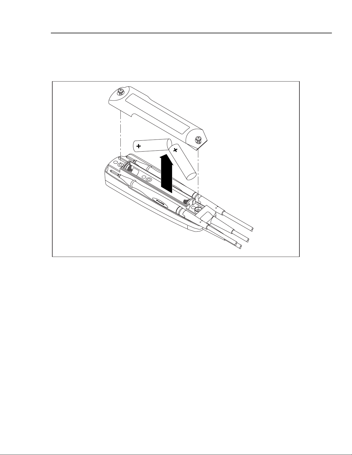
Battery Replacement
Battery Replacement
Replace the batteries when touching the leads together no longer turns on the continuity LED.
Figure 2 shows how to replace the batteries.
Tester
Figure 2. Replacing the Batteries
il2f.eps
7
Page 14
T3
Calibration Manual
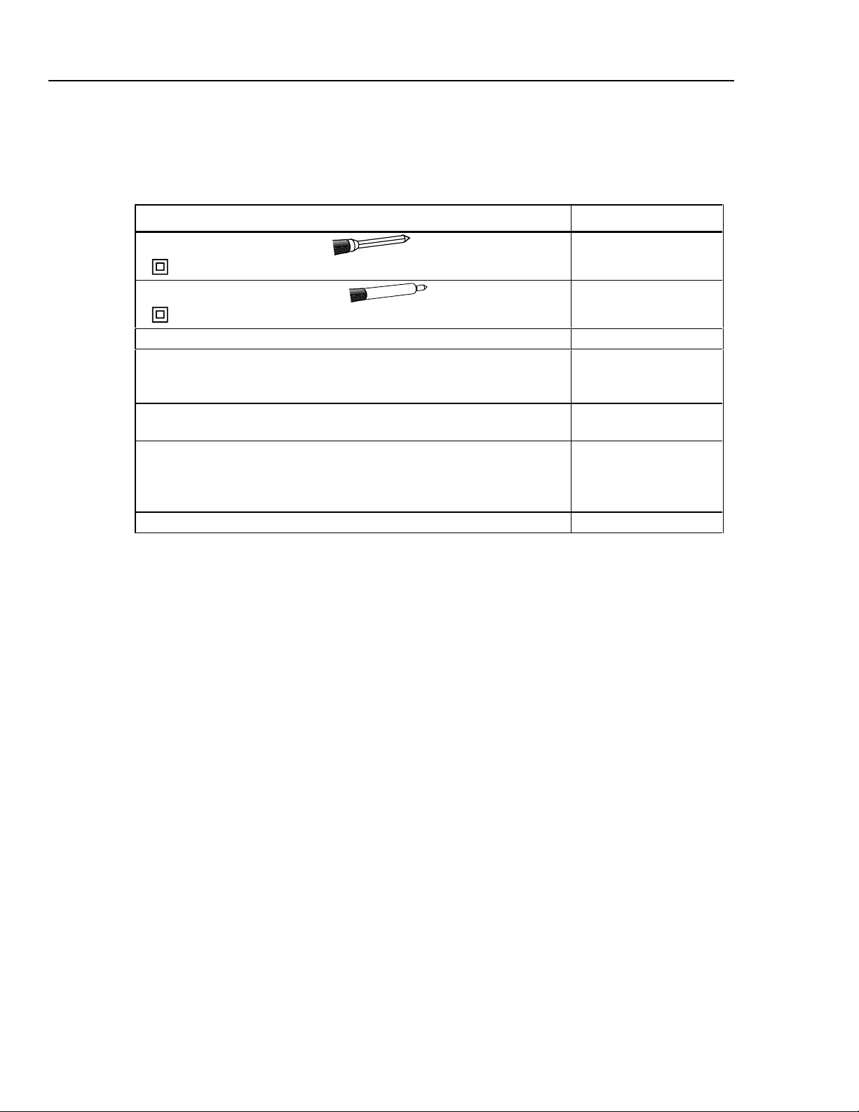
Parts and Accessories
Table 3 shows the replacement parts and accessories available from Fluke for the T3 Tester.
Table 3. Replacement Parts and Accessories
Description Fluke Part Number
Test lead assembly, flat blade
Replace only with Fluke double-insulated leads.
Test lead assembly, 4 mm round
Replace only with Fluke double-insulated leads.
Battery door 1576525
AA battery, 1.5 V, carbon-zinc (2 required)
or
AA battery, 1.5 V, alkaline (2 required)
T3 Tester Instruction Sheet Packages (Americas)
English, French, Spanish
T3 Tester Instruction Sheet Packages (International)
English, French, German, Italian, Finnish, Dutch, Danish, Norwegian,
Swedish, Spanish, Portuguese, Korean, Thai, Simplified Chinese,
Traditional Chinese
H5 Belt Holster Accessory
686733
688165
650181
376756
1562069
1562078
8
 Loading...