

Page 1

ROTALIGN® touch EX
On-board help
Page 2

ROTALIGNtouch
EX
On-board help
Version: 2.3
Edition: 03.2020
Part No.: DOC 52.202.EN
Page 3

Legal notices
© 2020 PRÜFTECHNIK. All rights reserved
Information in this document is subject to change without notice. The content
described in this document is distributed under a license agreement.
PRÜFTECHNIK assumes no responsibility or liability for any errors or inaccuracies that may appear in the informational content contained in this document. This document or parts thereof may not be reprinted or reproduced in
any form without written permission of PRÜFTECHNIK.
ROTALIGN is a registered trademark of PRÜFTECHNIK Dieter Busch AG.
PRÜFTECHNIK products are the subject of patents granted and pending
throughout the world. Contents are subject to change without further notice,
particularly in the interest of further technical development. Reproduction, in
any form whatsoever, only upon express written consent of PRÜFTECHNIK.
Page 4

Contents
Contents 3
System packages 9
Available package 9
Home screen 11
Configuration 13
Components 16
Ruggedized tablet 16
Starting the Shaft Alignment application 16
Intrinsically safe RF module 17
Intrinsically safe sensor and laser 17
sensALIGN5 EX components 19
sensALIGN 5 EX laser 19
Laser batteries 20
Replacing laser batteries 20
sensALIGN 5 EX sensor 21
Opening the sensor/laser aperture 21
Sensor and laser labelling 22
Mounting components 23
Mounting brackets 23
Bracket mounting procedure 23
Mount intrinsically safe RF module, sensALIGN5 sensor and laser 24
Dimensions 28
Coupling properties 29
Targets 29
Machine properties 31
Toggle 31
Machine colour 31
Thermal growth 32
ROTALIGNtouch EX│On-board help 3
Page 5

Thermal growth calculator 32
Multiple feet 34
Laser beam adjustment (sensALIGN 5 EX) 36
Using sensALIGN 5 laser and sensor 36
Laser beam adjustment 38
Laser adjustment wizard 38
XYView 40
Initializing sensor 43
Measurement 44
Averaging 44
Measurement modes 46
Continuous Sweep measurement 47
Extending measurement range when using Continuous Sweep 49
Multipoint measurement 51
Static measurement 53
Pass mode 55
Manual and dial gauge entries 57
Entering manual measurement values 57
Addition of a dial gauge measurement 58
Validity rule 60
Convert coupling results to dial gauge readings 61
Extend measurement range manually 63
Results 65
Sign convention 66
Multiple feet results 68
Foot corrections 68
Edition: 03.2020 4
Page 6

Tolerances 70
Available tolerance tables 70
ANSI standard specification tolerances 71
User defined tolerances 72
Asymmetric and symmetric tolerances 73
Tolerance table based on coupling format 74
Live Move screen 75
Move simulator 78
Saving asset measurements 80
Saving an asset 80
Asset list options 81
Default template 85
Generating reports 87
Generating measurement reports 87
Report logo 88
Measurement table 90
Measurement quality 92
Editing measurement data 93
Broken ellipse 93
Other deviation diagrams 94
What is the effect of deactivating individual points? 95
Using Cloud drive 96
Transferring an asset to the Cloud drive 96
Downloading an asset from Cloud drive 96
RFID 97
Assigning a saved asset to an RFIDtag 97
Opening an asset measurement assigned to an RFIDtag 98
Built-in camera 100
Gallery 100
How to capture a screen shot on the touch device 101
ROTALIGNtouch EX│On-board help 5
Page 7

Soft foot 102
Sensor measurement 102
Manual entry 103
Soft foot wizard 104
Types of soft foot 105
Vertical flanged machines 106
Marking measurement positions 106
Set-up 108
Vertical flanged machines – vertiSWEEP 110
Measure using vertiSWEEP 110
Shimming modes 112
Vertical flanged machines – Static clock 113
Measure using Static measurement mode 113
Live Move – Vertical machines 116
Correcting angularity 116
Correcting offset 116
Horizontal flanged machines 119
Flange-mounted horizontal machines 119
Set-up 119
Machine train alignment 121
Measurement 124
Live Move – machine train alignment 127
Cardan shaft alignment 130
Measurement procedures in the cardan application 130
Cardan shaft alignment - Using rotating arm bracket 131
Mounting laser, sensor and RF module 131
Mounting the brackets on the shafts 131
Cardan shaft alignment - Rotating plane measurement procedure 133
Taking measurements 134
Edition: 03.2020 6
Page 8

Cardan shaft alignment – Using cardan offset bracket 137
Cardan offset brackets 137
Mounting large cardan offset bracket 138
Mounting the large cardan offset bracket and adjusting laser 138
Mounting bracket 138
Mounting the laser holder assembly on the rail 140
Mounting and adjusting laser 140
Adjusting the laser beam to the machine rotational axis 140
Positioning laser and mounting sensor for measurement 140
Mounting cardan offset bracket lite (sensALIGN 5 EX laser) 141
Mounting the cardan offset bracket lite and adjusting sensALIGN 5 laser 141
Mounting the faceplate to the rail 141
Mounting the laser holder assembly on to the rail 143
Mounting and adjusting the sensALIGN 5 EX laser 143
Adjusting the sensALIGN 5 laser beam to machine’s rotational axis 144
Positioning sensALIGN 5 EX laser and mounting sensALIGN 5 EX sensor for measurement 145
Cardan shaft alignment measurement procedure 147
Evaluation and alignment 149
Best practice 151
Mounting sensor and laser 151
Entering dimensions 151
Initializing sensor 151
Causes that may influence measurement 151
Results and Live Move 151
sensALIGN 5 EX sensor firmware update 152
Updating sensor firmware to a newer version 152
Notification on sensor and laser calibration 154
Appendix 157
Updating ROTALIGN touch EX to a newer firmware version 157
Documentation 159
ROTALIGNtouch EX│On-board help 7
Page 9

Technical data – sensALIGN 5 EX sensor 161
Technical data – RFmodule 163
Technical data – sensALIGN 5 EX laser 165
Edition: 03.2020 8
Page 10
On-board help
System packages
The intrinsically safe ROTALIGNtouch EX system combines an intriniscally safe ruggedized tablet with the intrinsically safe sensALIGN 5 EX sensor and laser units.
The system incorporates built-in connectivity (WiFi and RFID), and a built-in camera. It is
available in the Zone 1 (Class I, Division 1) category.
Available package
l ALI 52.000-Z1 — This package uses the ecom Class I, certified ruggedized tablet ALI
52.200-Z1
Note
Check and ensure that the delivered package items conform to the purchase order and
the packing list. Reference may also be made to the online product catalog.
Contact PRÜFTECHNIKCondition Monitoring or your local sales representative if any
package items are damaged or missing.
ROTALIGNtouch EX 9
Page 11

This page intentionally left blank
Page 12
On-board help
Home screen
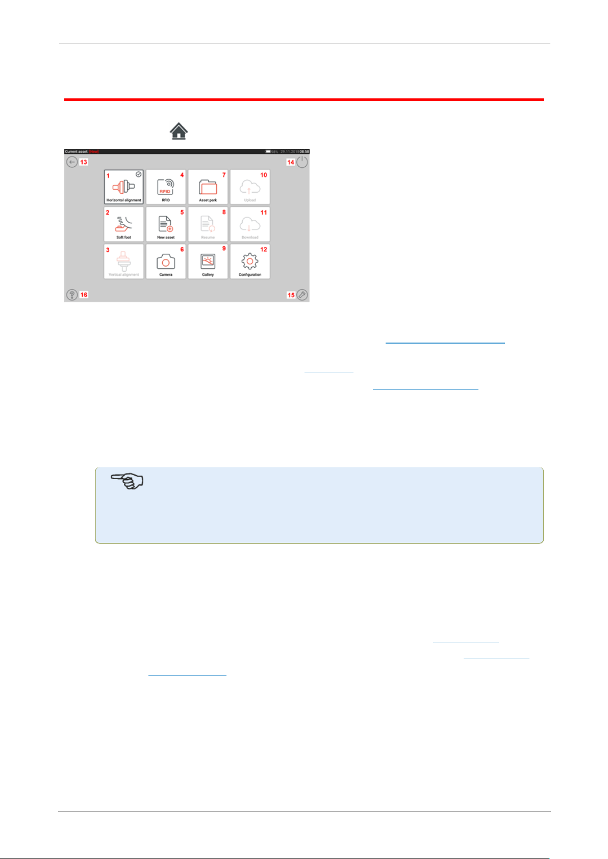
The home screen is displayed when the device is switched on. The home screen may also be
accessed by tapping the "Home" icon.
Tapping the respective icon accesses the following respective functions:
l (1) The "Horizontal alignment" icon is used to access the horizontal alignment applic-
ation.
l (2) The "Soft foot" icon is used to access soft foot measurement.
l (3) The "Vertical alignment" icon is used to access the vertical alignment application.
If this icon is inactive, tap the "New asset" icon(5) to activate the vertical alignment
icon.
l (4) The "RFID"icon is used to open assets assigned to respective RFID tags.
l (5) The "New asset" icon is used to start a new asset (this may be a pump-motor com-
bination).
l
Note
For any opened asset, different applications that may include shaft alignment and
soft foot measurement, may be performed.
l (6) The "Camera" icon is used to access the built-in camera.
l (7) The "Asset park" icon is used to display all saved assets and templates.
l (8) The "Resume" icon is used to resume last asset opened (provided it was saved)
when the device is switched on.
l (9) The "Gallery" icon is used to display all images taken within the Shaft application.
l (10) The "Upload" icon is used to save asset measurements in the Cloud drive.
l (11) The "Download" icon is used to open asset measurements from the Cloud drive.
l (12)The "Configuration" icon is used to configure the Shaft application settings (which
include language, date, time, default settings), and access its built-in mobile connectivity. Mobile connectivity enables the device to access the Cloud functionality that
allows wireless file sharing.
l (13) The "Back" icon is used to return to previous screen.
l (14) The "Power-off" icon is used to turn the touch device off.
l (15) The "Camera LEDon/off" icon is used to turn the camera LEDs on/off.
l (16) The "Help" icon is used to access the on-board help file.
ROTALIGNtouch EX 11
Page 13

On-board help
12 Version:2.3
Page 14
Configuration
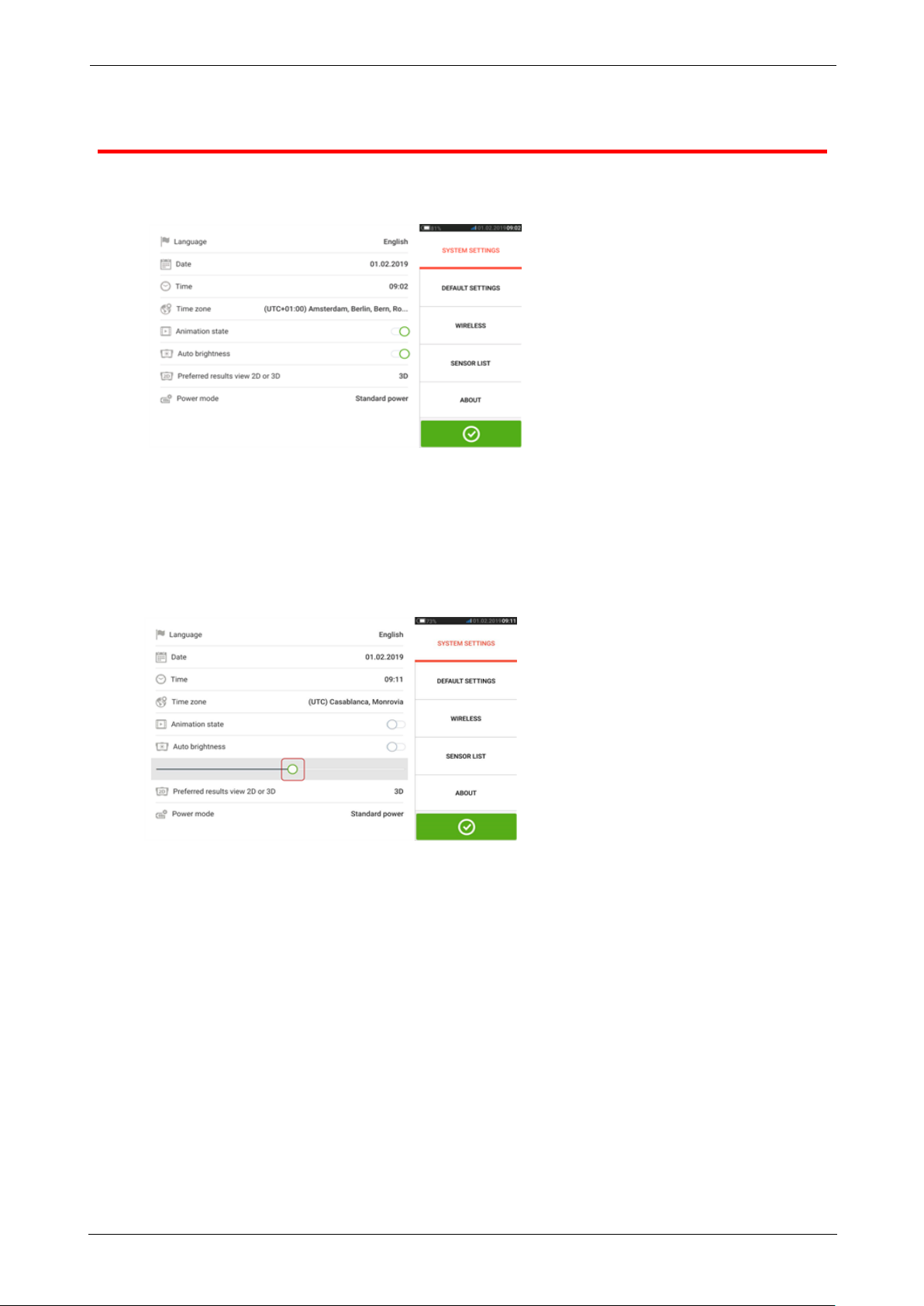
The following settings and items may be accessed via the configuration icon:
l 'System settings' sets the following items:
> Language (system language); > Date; > Time; > Time zone;
> Animation state — regulates the transition between the dimension, measure and results screens. Two options are available – fast and standard. If "Animation state" is on,
the transition between screens is set to standard and therefore noticeable. If off, the
transition is fast.
> Auto brightness – adjusts the display brightness of the touch device. If "Auto brightness is on, the display brightness adjusts automatically. If off, then the display brightness may be manually adjusted by dragging the brightness slider to the left or right.
On-board help
> Preferred results view 2D or 3D
> Power mode – used to manage the power usage in the touch device. Four power
scheme options are available.
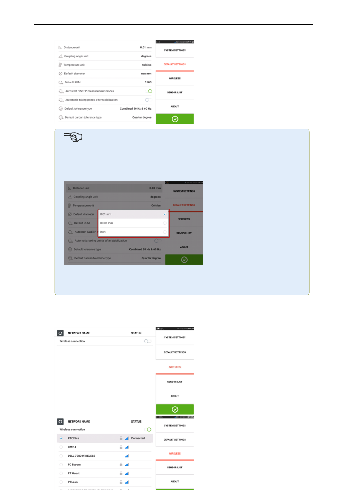
l 'Default settings' is used to set units of length, angle and temperature; the default dia-
meter may be set here. It is also used to activate or deactivate the automatic start of
Sweep as well as automatic taking of readings after stabilization, especially in point
measurement modes. Type of tolerance to be used may also be set here.
ROTALIGNtouch EX 13
Page 15
On-board help
Note
When using metric units, the resolution of physical quantities used within the
device may be set to two (0.01 mm) or three (0.001 mm) decimal places. This
measurement precision is available in "Measurement", "Results" and "Live Move"
screens. The "Dimensions" screen uses only positive integers.
The set time zone is coupled to the default RPM unless the default RPM is edited
independently. Setting the time zone to say "Central America" results in a default
RPM of 1800. Setting the "London" time zone results in a default RPM of 1500.
l When activated, 'Wireless connection' is used to connect the touch device to available
WiFi networks.
14 Version:2.3
Page 16
Note
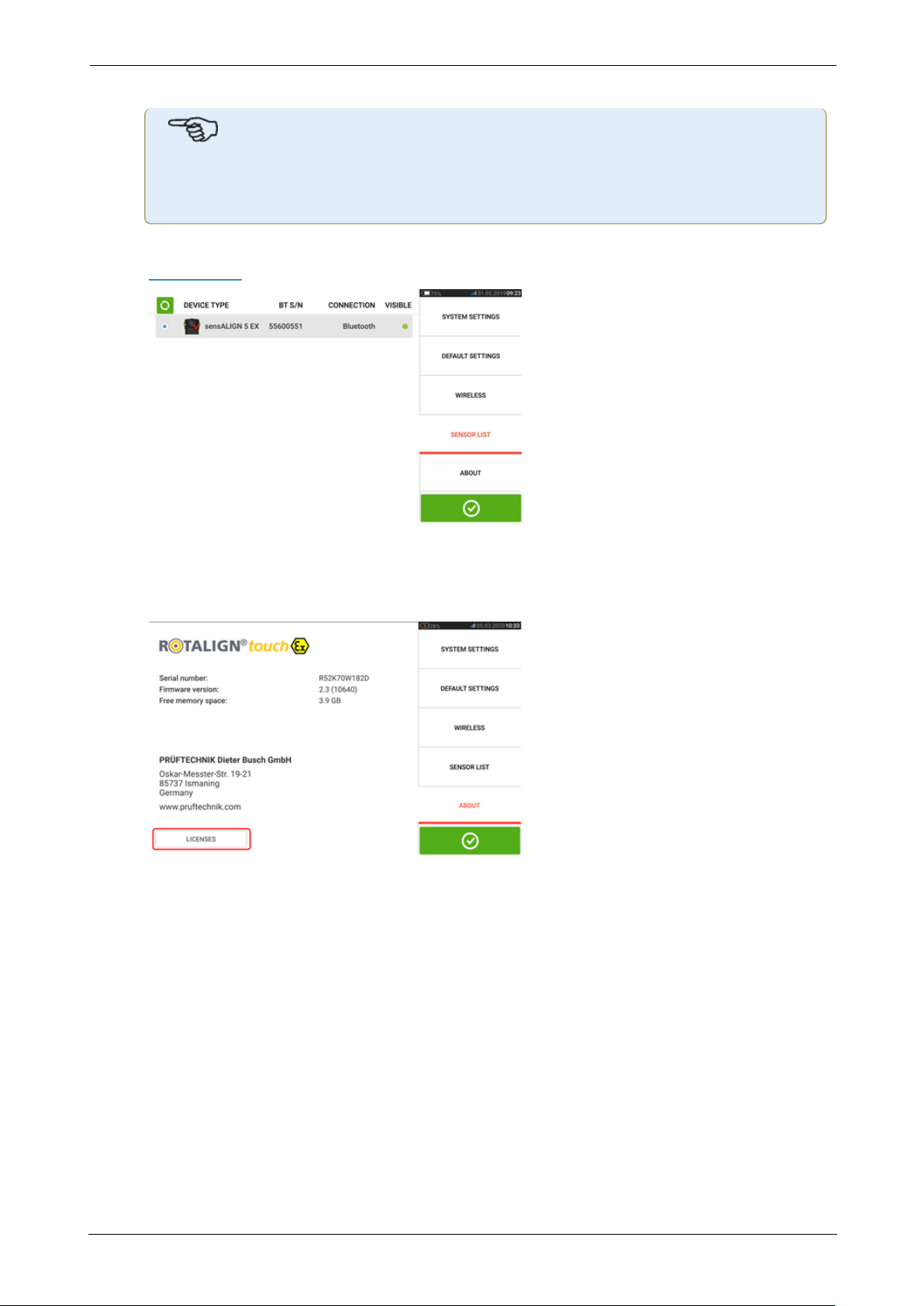
The touch device may be connected only to WiFi networks that do not open separate web browsers to login.
l 'Sensor list' displays all available sensors.
On-board help
l The "About" screen displays the device features level (ROTALIGNtouch EX ), serial num-
ber, firmware version of the application and available memory space.
Open source licenses and other Android legal requirements may also be accessed via
this screen by tapping "LICENSES".
ROTALIGNtouch EX 15
Page 17
On-board help
Components
The main measuring components for shaft alignment are the intrinsically safe ruggedized tablet, the intrinsically safe sensor, the intrinsically safe laser and the intrinsically safe RF module.
Ruggedized tablet
Note
For details on usage of the ruggedized tablet please refer to the included ecom tablet
manual.
The only application running on this intrinsically safe ruggedized tablet is Shaft Alignment. Additional apps cannot be installed in this dedicated device.
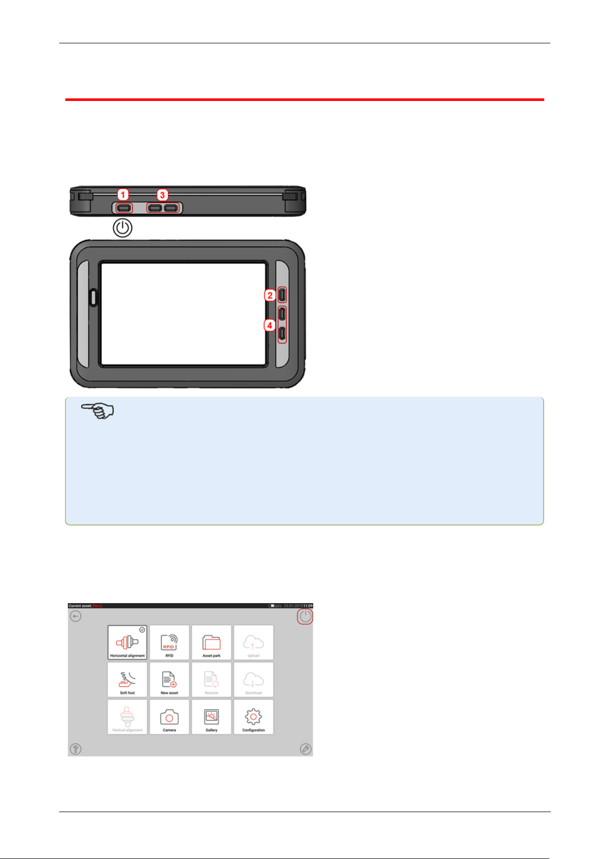
In this version of the tablet device, the hard keys (3 and 4) have been disabled. The
hard key (2) may be used to capture screenshots.
Starting the Shaft Alignment application
Switch the ruggedized tablet on by pressing and holding down the power key (1). Once
switched on, the application home screen opens.
16 Version:2.3
Page 18
On-board help
Tap the power icon [ ] appearing in the home screen to exit the application, and sends the
ruggedized tablet to sleep mode.
Note
To switch the ruggedized tablet off, press and hold down the power hard key, and then
tap the "power off" icon that appears on the display.
Intrinsically safe RF module
The intrinsically safe RFmodule is used for wireless communication between the intrinsically
safe sensor and the intrinsically safe ruggedized tablet.
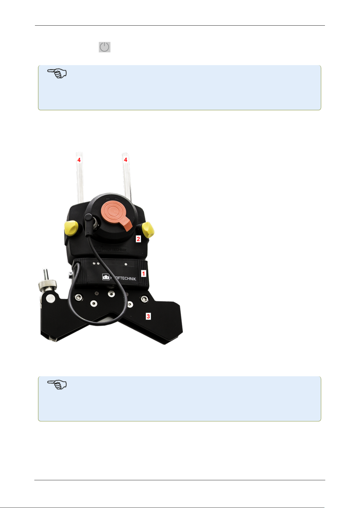
1: Intrinsically safe RF module; 2: Intrinsically safe sensALIGN 5 sensor; 3: Bracket frame for
the supplied compact chain-type bracket set; 4: Support posts for the supplied compact chaintype bracket set
Note
For details on the intrinsically safe RF module please refer to the included RF module
operating handbook DOC 04.202.
Intrinsically safe sensor and laser
Refer to "sensALIGN5 EX components" on page19
ROTALIGNtouch EX 17
Page 19

On-board help
Information on the sensor and laser may be found in the related topic below.
18 Version:2.3
Page 20
On-board help
sensALIGN5 EX components
sensALIGN 5 EX laser
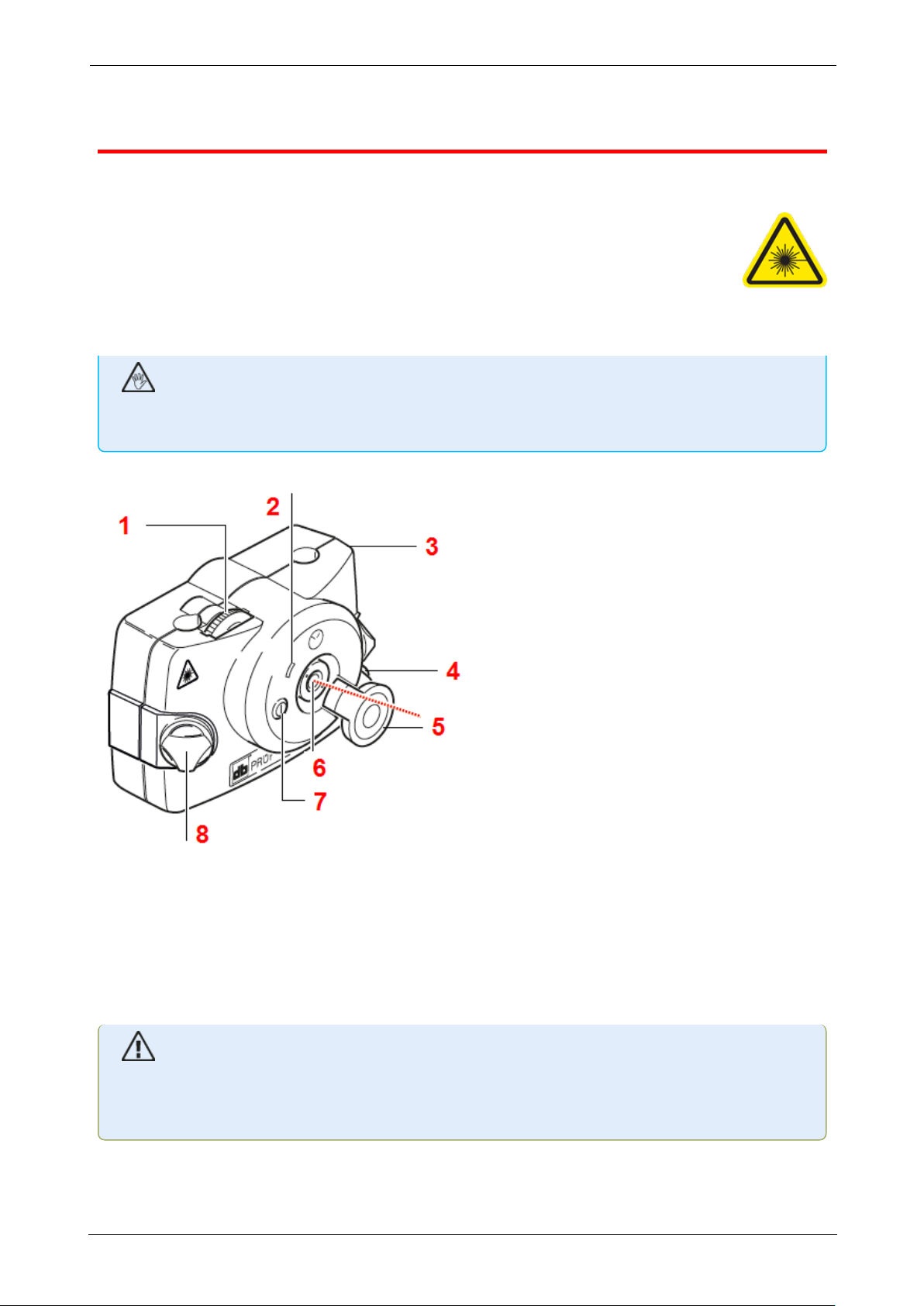
The semiconductor laser diode emits a ray of red light (wavelength 630 – 680 nm)
which is visible where it strikes a surface. The Class 2 laser beam is emitted with a
diameter of approx. 5 mm (3/16”).
The laser is turned on by pressing its On/Off push button switch. The “beam active”
LED lights red.
WARNING
With the laser on, DONOTstare into the laser beam!
1: Vertical beam position adjustment thumbwheel; 2: “Beam active” indicator LED; 3: Rubber
housing; 4: Horizontal beam position thumbwheel; 5: Laser dust cap in “open position”; 6:
Laser emission aperture; 7: On/Off push button switch; 8: Locking knob
The beam is adjusted during set-up by changing its vertical and horizontal angles using the position thumbwheels, so that the beam strikes the sensor lens perpendicular to the lens surface.
The laser is water and dust resistant (IP 65). The internal optics and electronics are internally
sealed, preventing possible contamination.
CAUTION
The battery compartment is not watertight. If water enters this compartment, open it
and dry it out. The two AA size batteries should then be replaced.
ROTALIGNtouch EX 19
Page 21
On-board help
Laser batteries
The laser is powered using two high energy AA size alkali-manganese 1.5 V batteries (use only
Duracell Industrial ID 1500 or Energizer E91). These provide a typical operating duration of
120 hours.
CAUTION
As the battery becomes depleted, the colour of the ‘laser active’ indicator LED changes
from green (full) to yellow (half full) to red (empty). When this occurs, the batteries
should be replaced.
If the laser is not in use for extended periods of time, a month or more, the batteries
should be removed from the unit.
Replacing laser batteries
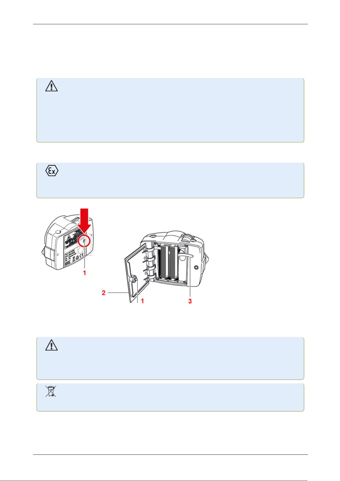
Batteries must be changed only outside the explosive area! Note that only alkali-manganese batteries can be used in explosive atmospheres.
The batteries are replaced by undoing the quarter-turn screw (1) on the battery compartment
cover (2) by rotating it by at least 90° (1/4 turn). With the screw loosened, lift the cover, and
then use the red strap (3) to remove the batteries. Replace both batteries at the same time.
CAUTION
Under no circumstances may the two smaller housing hex head screws be removed, as
that would void all warranty coverage.
Used batteries should be disposed of in an environmentally-sound manner!
20 Version:2.3
Page 22
On-board help
sensALIGN 5 EX sensor
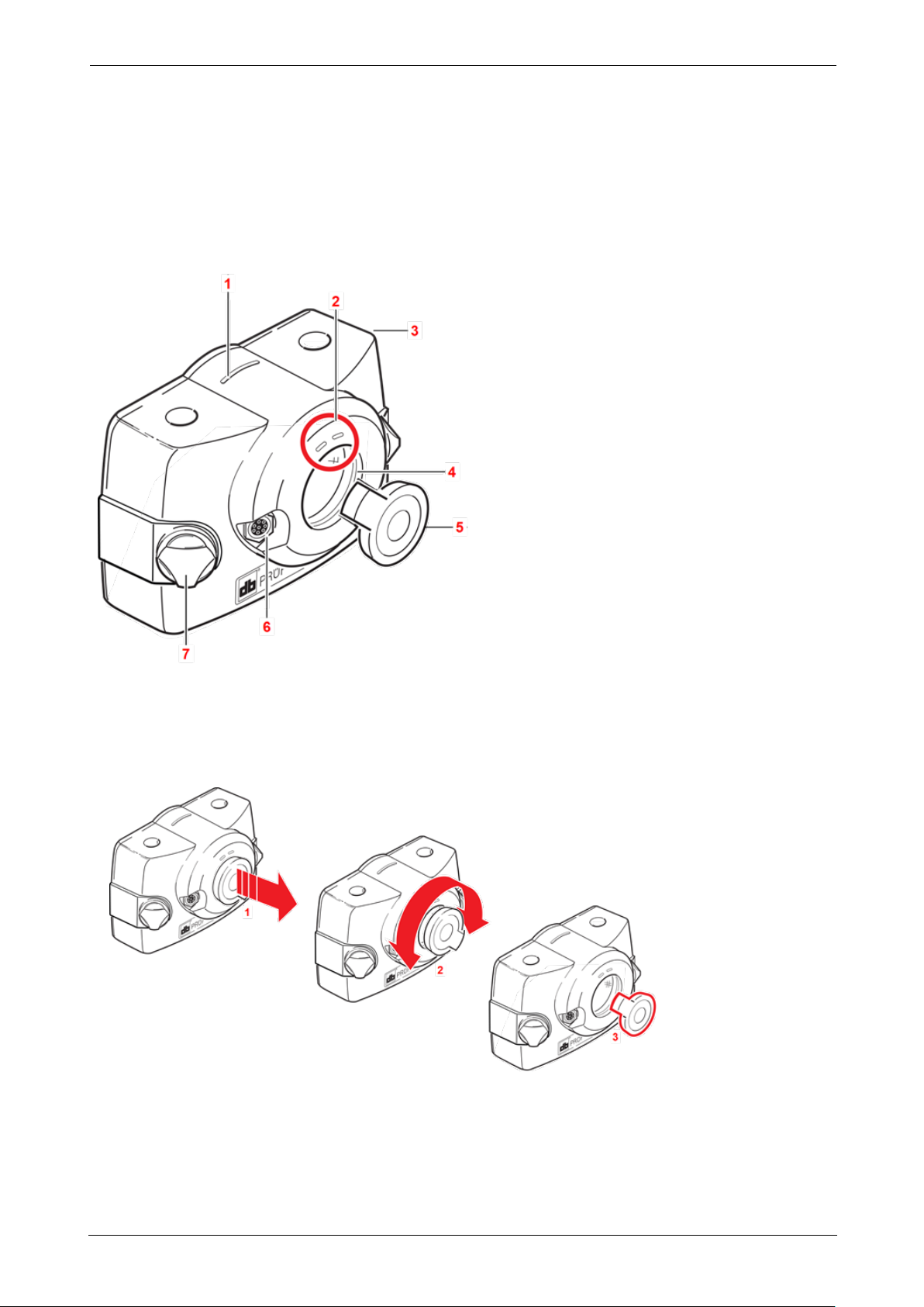
The sensor contains two position detectors, which measure the exact position of the laser
beam as the shafts are rotated. The sensor also contains an electronic inclinometer for shaft
rotation measurements.
The sensor has two indicator LEDs on its front side, one green and the other red, to indicate
beam adjustment.
The sensor is powered using the intrinsically safe RFmodule via the module cable.
1: Distance marking; 2: Laser beam position LEDs; 3: Rubber housing; 4: Scratch-resistant
lens; 5: Sensor dust cap in “open position”; 6: Cable socket; 7: Locking knob
Opening the sensor/laser aperture
l (1) Lift the dust cap slightly in the direction shown by the bold red arrow.
l (2) Rotate the dust cap in either direction as shown by the bold red arrow.
l (3) Lock the dust cap in its “open position” highlighted in red.
ROTALIGNtouch EX 21
Page 23
On-board help
Sensor and laser labelling
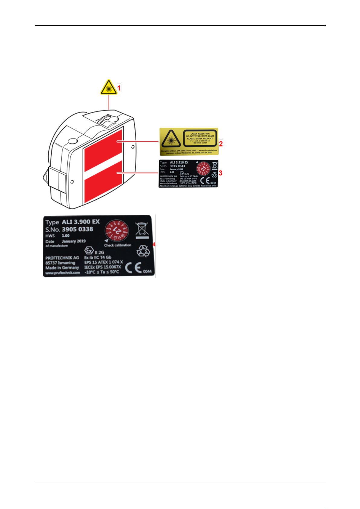
Labels used in communicating laser safety and other general information are to be found
affixed to the housing of the system components.
l (1) The laser beam hazard symbol label is affixed at the front of the laser head.
l (2) The laser safety warning label is affixed to the back of the laser.
l (3) The laser identification label and the laser inspection label are affixed to the back of
the laser.
l (4) The sensor identification label and the sensor inspection label are affixed to the back
of the sensor.
22 Version:2.3
Page 24
On-board help
Mounting components
Mounting brackets
Note
The system is delivered with fully assembled brackets, and with the intrinsically safe
sensALIGN 5 laser, sensALIGN 5 sensor and RF module already assembled. In this case,
the bracket holding the laser is mounted on the shaft on the left side of the couplings or
the solid coupling hub on the left side. The bracket assembly holding the sensor connected to the RF module is mounted on the shaft on the right side of the couplings or the
solid coupling hub on the right side.
Mount the brackets on either side of the coupling on either the shafts or on the solid coupling
hubs, and both at the same rotational position.
Please note the following in order to obtain the highest possible measurement accuracy and to
avoid damage to equipment:
CAUTION
Ensure that the brackets fit solidly onto their mounting surfaces! Do not use self-constructed mounting brackets, or modify the original bracket configuration supplied by
PRÜFTECHNIK (for example, do not use support posts longer than those supplied with
the bracket).
Note
If the brackets have not been fully assembled, follow the mounting procedure below.
Bracket mounting procedure
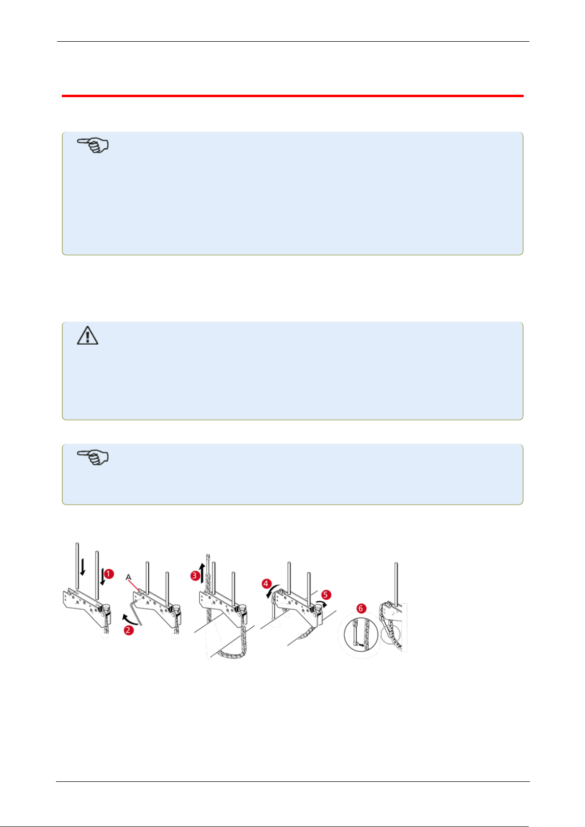
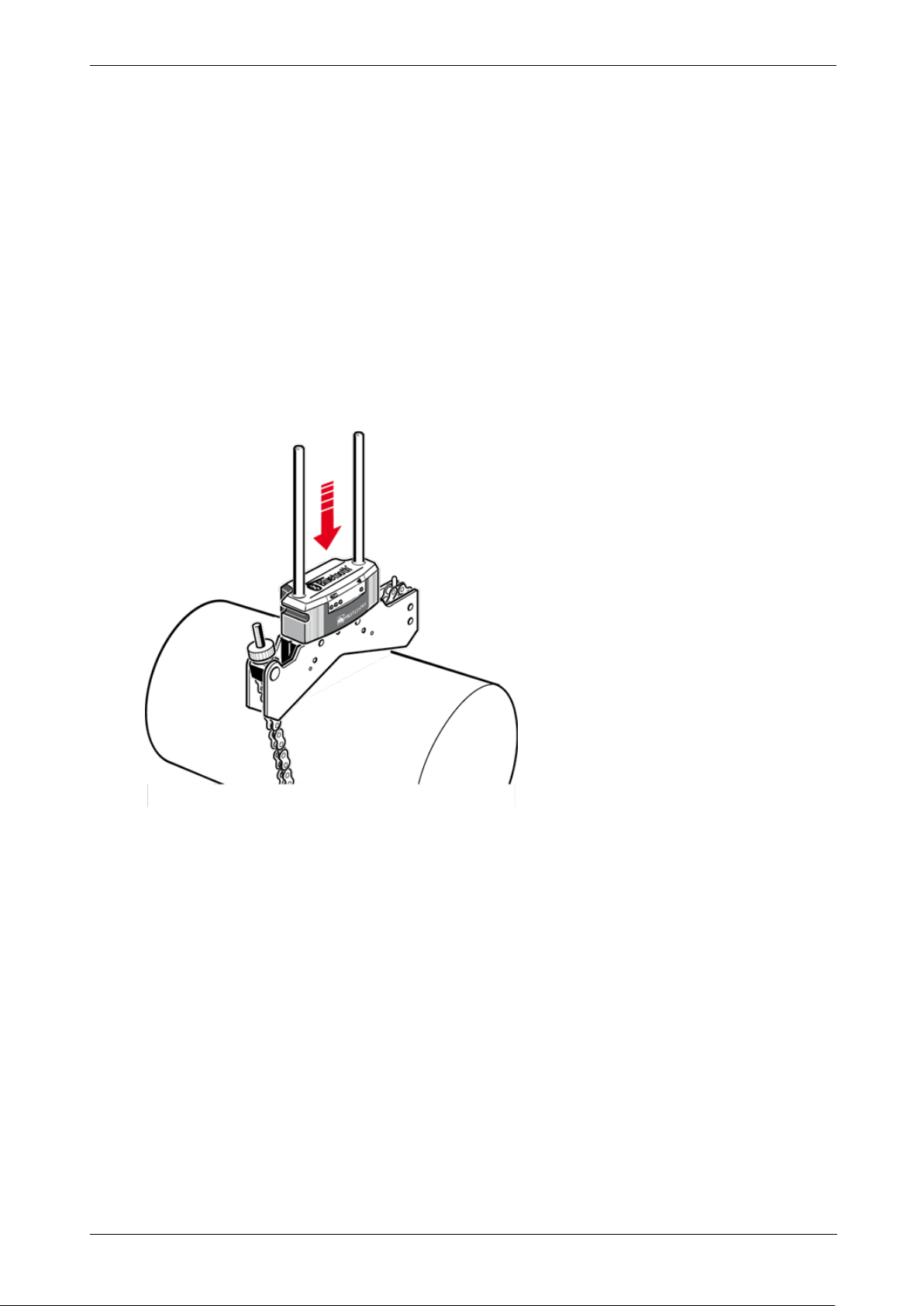
l Choose the shortest support posts which will still allow the laser beam to pass over or
through the coupling. Insert the support posts into the bracket.
l Fasten them in place by tightening the hex screws on the sides of the bracket frame.
l Place the bracket on the shaft or coupling, wrap the chain around the shaft and feed it
through the other side of the bracket: if the shaft is smaller than the width of the bracket
ROTALIGNtouch EX 23
Page 25
On-board help
frame, insert the chain from the inside of the bracket as shown in the diagram; if the
shaft is larger than the bracket width, insert the chain into the frame from the outside.
l Catch the chain loosely on the anchor peg (A).
l Turn the bracket thumbscrew to tighten the assembly onto the shaft.
l Clip the loose end of the chain back onto itself.
The bracket should now be tight upon the shaft. Do not push or pull on the bracket to check,
since this could loosen its mounting.
To remove the brackets, loosen the thumbscrew, then remove the chain from its anchor peg.
Mount intrinsically safe RF module, sensALIGN5 sensor and laser
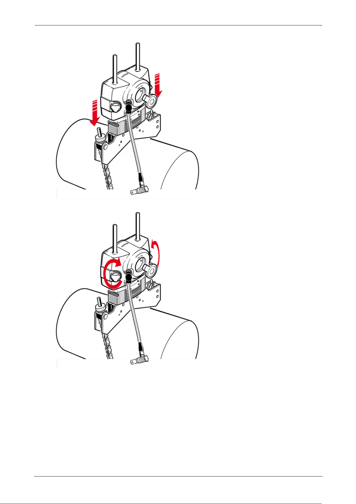
l Mount the RF module on the support posts of the bracket fixed on the shaft of the right
machine (usually moveable machine). The module clamps on the support posts. It is
recommended to slide the RF module all the way down onto the bracket frame.
l Mount the intrinsically safe sensALIGN 5 sensor on the same support posts as the RF
module. The yellow locking knobs should be loose enough to allow the sensor slide onto
the support posts. Lower the sensor as close to the RF module as possible.
24 Version:2.3
Page 26
On-board help
l Clamp the sensor onto the support posts by tightening the yellow knobs.
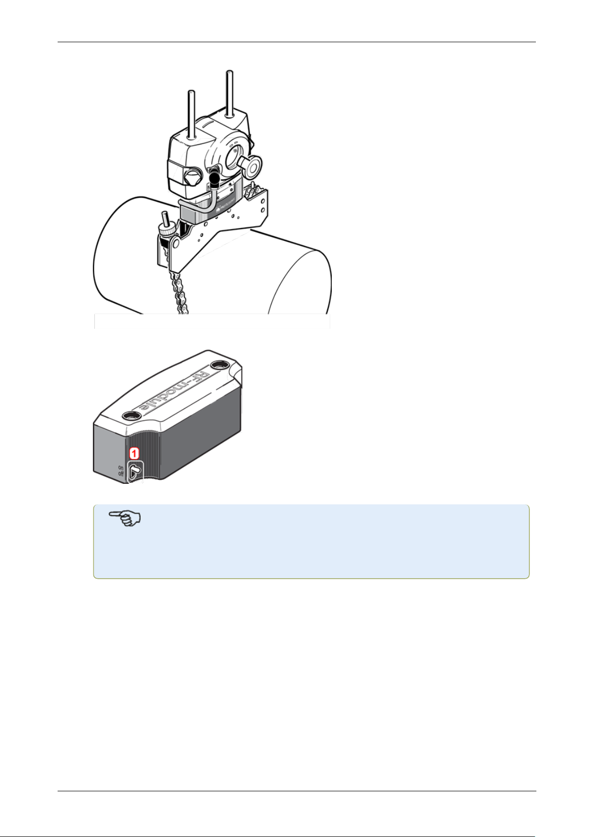
l Connect the sensor to the RF module using the RF module cable.
The shorter 90-degree connector of the RF module cable is connected to the 8-pin sensor
socket. The keyway orientation should be noted, and the knurled sleeve of the connector
screwed in until it is snug. The longer 90-degree connector of the RF module cable is
inserted into the four-pin socket on the side of the RF module with a groove, matching
the red dot on the plug to the groove on the socket to ensure proper plug orientation.
ROTALIGNtouch EX 25
Page 27
On-board help
l Use its power switch (1) to turn the intrinsically safe RF module on.
The intrinsically safe RF module powers the intrinsically safe sensor.
Note
For details on the intrinsically safe RF module please refer to the included RF module operating handbook DOC 04.202.
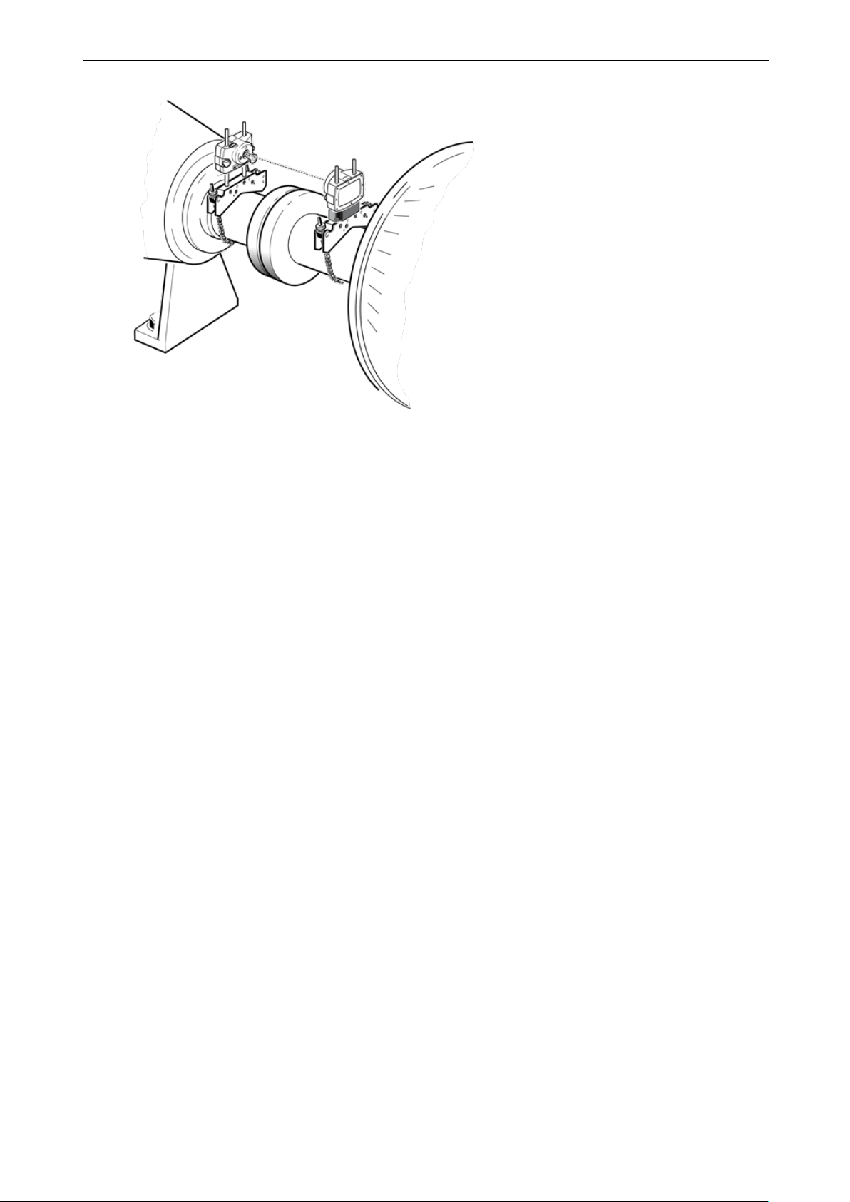
l Mount the intrinsically safe sensALIGN 5 laser on the support posts of the bracket fixed
on the shaft of the left machine (usually reference machine) – as viewed from normal
working position. Ensure that the yellow locking knobs are loosened enough to let you
slide the housing onto the support posts.
Switch the laser on by pressing its On/Off push button (1). Ensure that the laser beam
can pass over or through the coupling and is not blocked.
26 Version:2.3
Page 28
On-board help
Both the sensor (3) and laser (2) should be at the same height, as low as possible, yet high
enough for the beam to clear the coupling flange. They should also visually appear to be rotationally aligned to each other.
Make the final adjustments, loosening the brackets slightly if necessary, then rotating them,
and re-tightening.
In some cases, if the coupling is large enough, a coupling bolt can be removed and the laser
beam shot through the bolt hole, in order to avoid protruding radially beyond the coupling's
outer diameter (O.D.).
Both sensor and laser should be at the same height, as low as possible, yet just high enough
for the beam to clear the coupling flange. They should also visually appear to be rotationally
aligned to each other.
ROTALIGNtouch EX 27
Page 29
On-board help
Dimensions
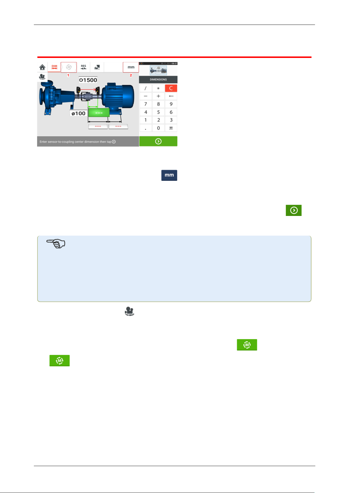
l (1) Grayed out icons are disabled within the active screen. The 'Measure' icon is
enabled after all dimensions have been entered.
l
(2) Tap the measurement units icon to set desired units. The icon toggles between
"mm" and "inch".
Tap the dimension fields and enter all required dimensions. The user may elect to tap
the ‘Next’ button to proceed to enter next dimension. Dimensions may be entered only when
the dimension field is highlighted green.
Note
If units are set to Imperial system, inch fractions may be entered as follows: For1/8"
enter 1/8 = 0.125"; For 103/8" enter 10 + 3/8 = 10.375".
Thecouplingdiametervaluemaybedetermined by entering the measured circumference of the coupling and dividing the value by π (pi) (=
3.142).Forexample33"/π=10.5";Or330 mm/π=105mm
The rotate machine view icon is used to rotate the view of the machines and mounted components on the display.
Machine and coupling properties may be edited by tapping the respective machine or coupling.
When all required dimensions have been entered, the ‘Measure’ icon appears.
Tap to proceed with measurement.
28 Version:2.3
Page 30
On-board help
Coupling properties
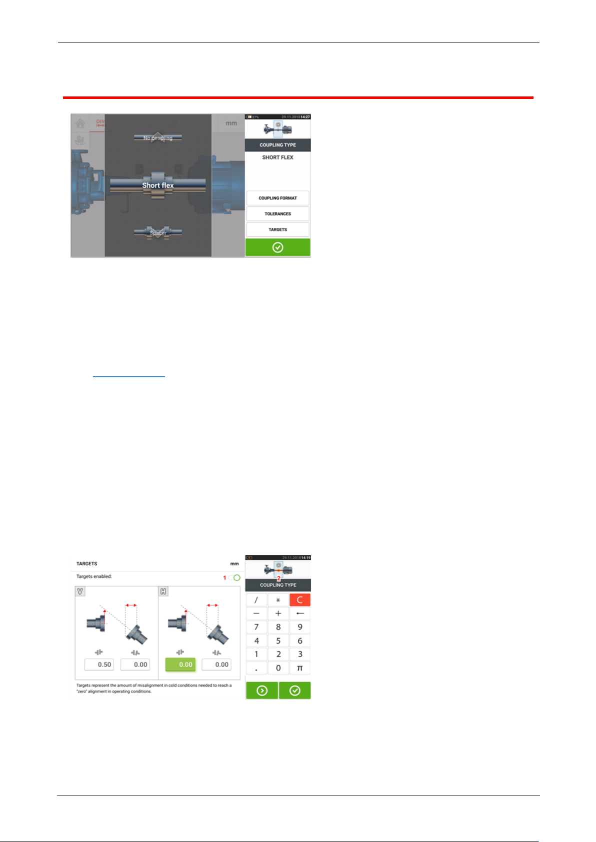
Swipe the carousel up or down and select desired coupling type.
The following coupling types are available for selection:
l Short flex — These couplings feature fitted transmission elements with play (such as
teeth, claws or bolts) or elastic connecting elements like rubber ‘tires’ or springs.
l Spacer shaft — When the coupling halves are joined by a spacer element, its length
must be entered.
l Cardan shaft — Just as with regular spacer shafts, the shaft length (between coupling
planes) must be entered.
l Single plane — The coupling halves are bolted directly together. Loosen the bolts before
taking measurements, since they would otherwise distort the true alignment condition.
l No coupling — This coupling format is intended for use with CNC machines. In this
format, the length between the two shafts must be entered. The measurement mode for
this coupling format is Multipoint.
Targets
Targets are misalignment values specified as an offset and an angle in two perpendicular
planes (horizontal and vertical) and used to compensate for dynamic loads.
Access the coupling targets screen by tapping the item "Targets".
The displayed coupling format depends on the type of coupling selected.
To enter any target specifications at the coupling, tap the corresponding value box then pro-
ceed to enter the target value using the onscreen keyboard. Cycle through the value boxes
ROTALIGNtouch EX 29
Page 31

On-board help
using . Alternatively, tap the desired value box.
Target specification values are activated by swiping the icon to the right [1]. When target values are enabled, the coupling [2]within the mini train inset at the top-right corner
appears in orange. After target values have been entered, tap to proceed.
30 Version:2.3
Page 32
On-board help
Machine properties
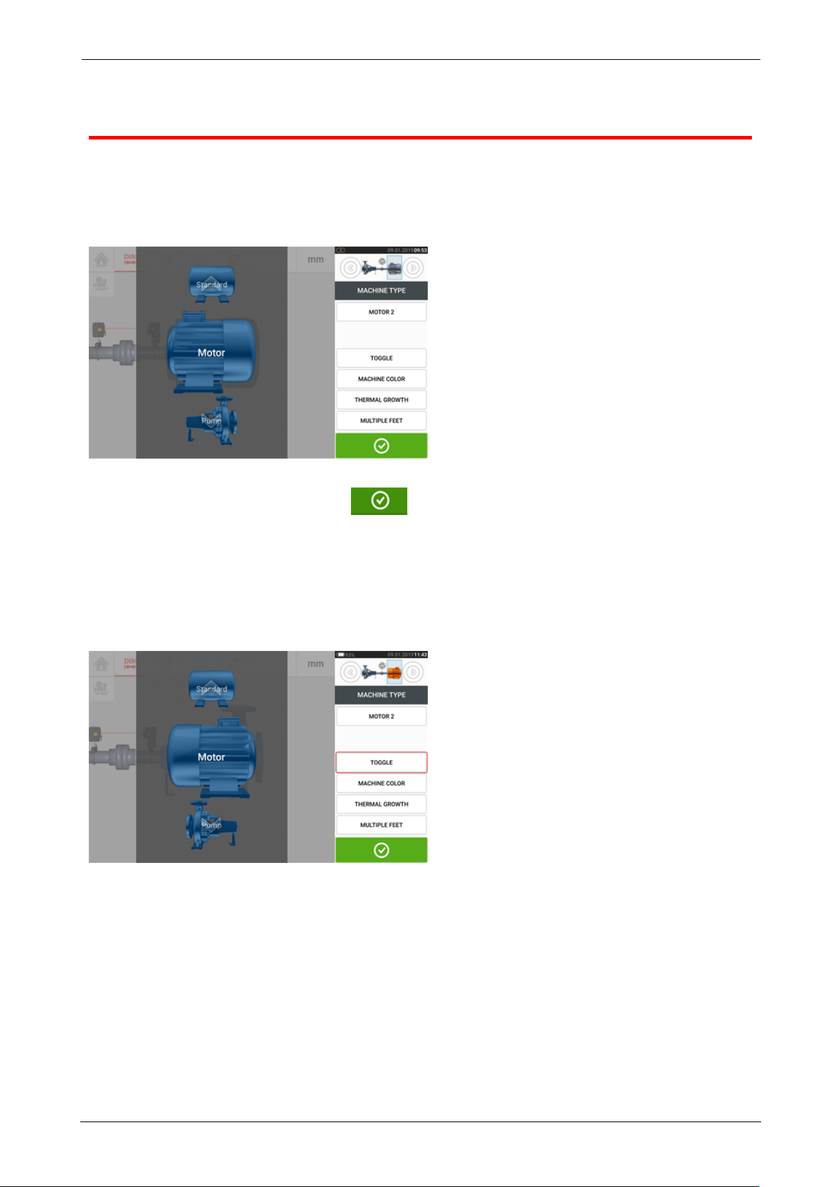
The following lifelike machine graphics are available:
1. Generic standard machine; 2. Motor; 3. Pump; 4. Split case pump; 5. Fan; 6. Center hung
fan; 7. Blower; 8. Compressor; 9. Gearbox; 10. Rotor gearbox; 11. Diesel engine; 12. Generator; 13. Gas turbine; 14. Shaft with no supports; 15. Shaft with a single support; 16. Shaft
with two supports
Swipe the machine carousel up or down and select desired machine. Position desired machine
at the centre of the carousel then tap to confirm selection and return to the dimensions screen.
Toggle
"Toggle" is used change the orientation of the selected machine along the shaft axes. In the following example, the motor has been flipped so as to connect the non-drive side to the coupling.
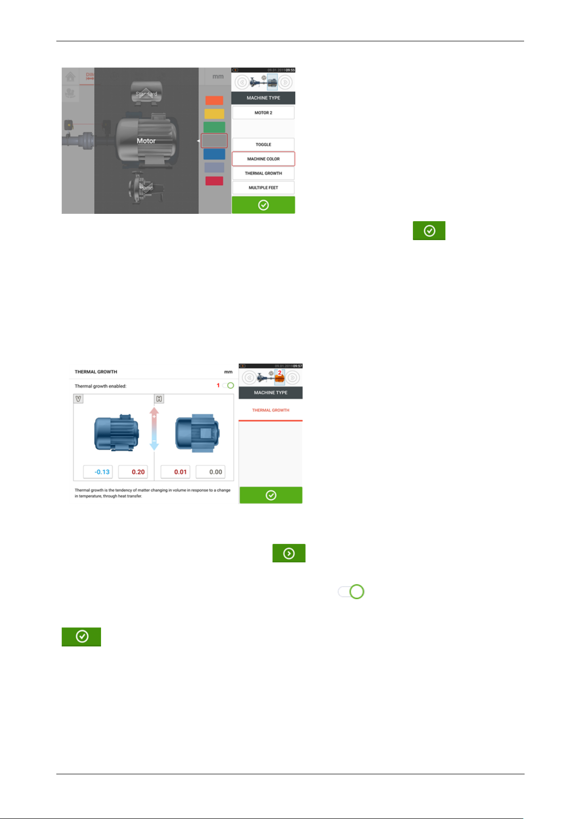
Machine colour
The desired machine colour may be set from this screen by tapping the item "Machine colour".
A colour palette appears.
ROTALIGNtouch EX 31
Page 33
On-board help
Swipe the colour palette up or down to select the desired colour then tap to confirm
selection and return to the dimensions with the machines having the desired colour.
Thermal growth
Thermal growth is the movement of shaft centerlines associated with or due to a change in
machinery temperature between the idle and operating conditions.
Access the thermal growth screen by tapping the item "Thermal growth".
Thermal growth values can be entered only when machine feet have been defined.
To enter any specified thermal growth value at the required foot position, tap the corresponding value box then proceed to enter the thermal growth value using the onscreen key-
board. Cycle through the value boxes using . Alternatively, tap the desired foot
position.
Thermal growth values are activated by swiping the icon to the right [1]. When thermal
growth values are enabled, the corresponding machine within the mini train inset at the topright corner appears in orange [2]. After thermal growth values have been entered, tap
to proceed.
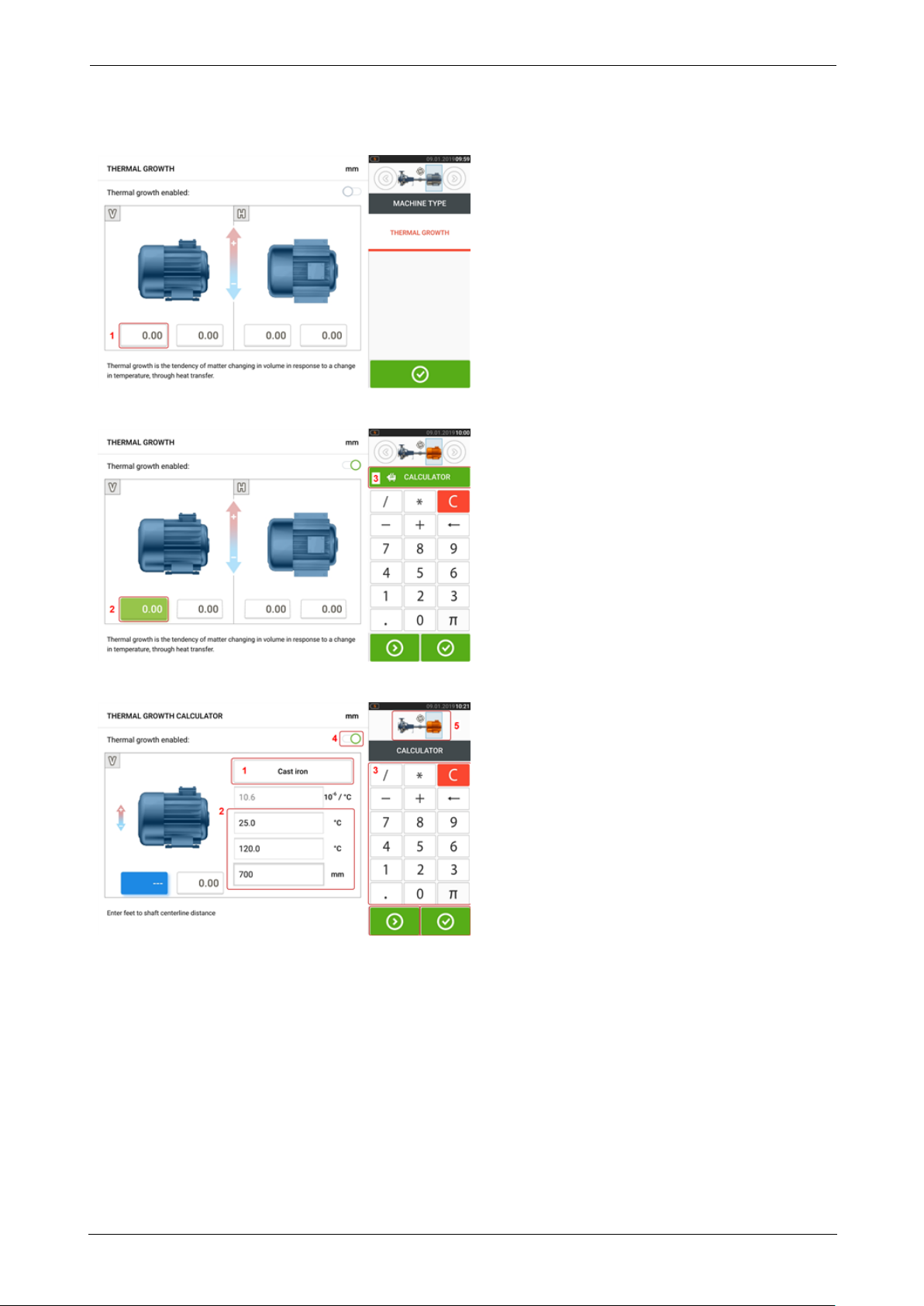
Thermal growth calculator
The calculator is used to calculate thermal growth compensation if no other values are available. Thermal growth is calculated from the material coefficient of linear thermal expansion,
expected temperature difference and length of the shaft centerline from the shim plane.
32 Version:2.3
Page 34
On-board help
After accessing the thermal growth screen, tap value box of feet pair [1] where thermal
growth is to be entered.
The box is highlighted green [2], and the 'Calculator' tab [3] appears.
Tap 'Calculator' tab [3] to access the thermal growth calculator screen.
Tap (1) and select machine material. The corresponding linear thermal expansion appears.
Enter the three values [2] required to calculate the thermal growth value for the selected feet
pair using the onscreen keyboard [3]. The three values are:
l Ambient temperature (initial temperature)
l Machine running temperature (final temperature)
l Distance from machine base (or shimming plane) to the shaft centerline (length)
With thermal growth values enabled [4], the corresponding machine within the mini train inset
at the top-right corner appears in orange [5].
ROTALIGNtouch EX 33
Page 35
On-board help
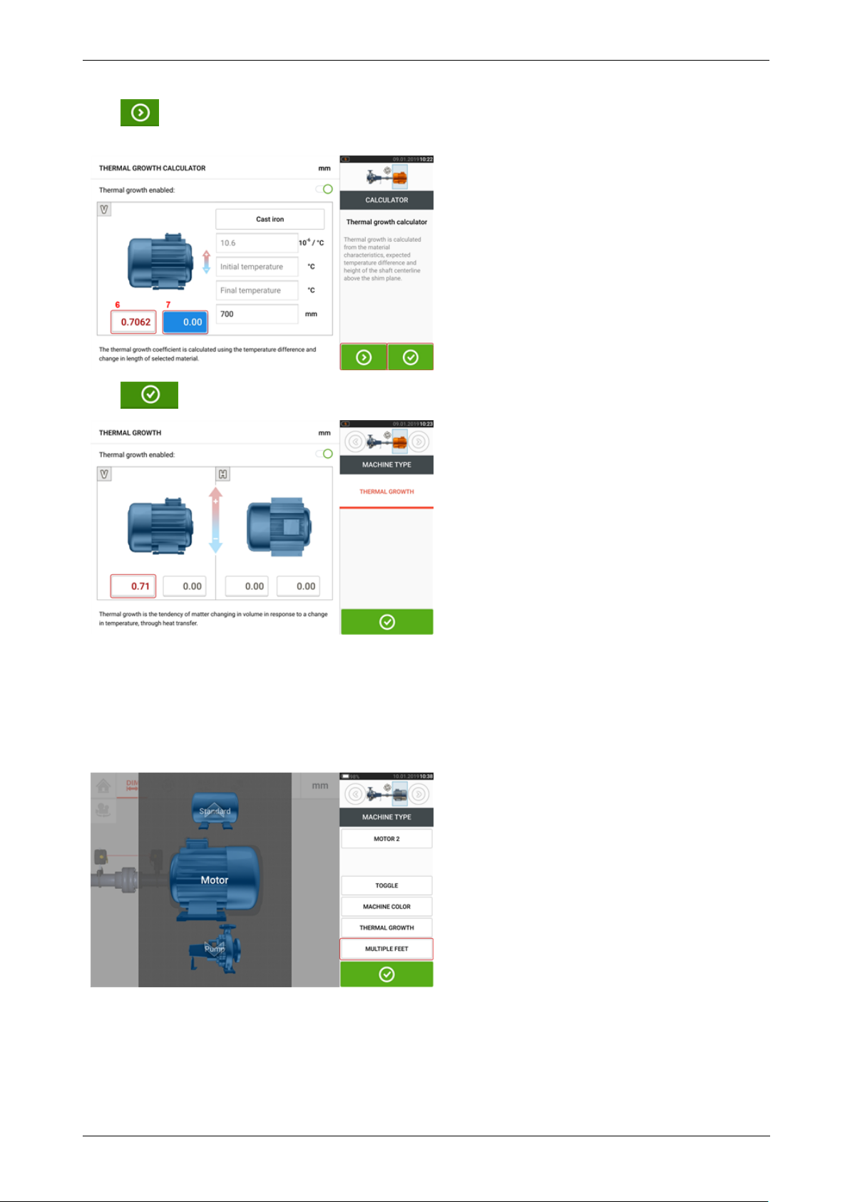
Tap to simultaneously display the calculated thermal growth value for the respective
feet pair [6] and toggle to the next feet pair [7].
Tap to return to the thermal growth screen showing the calculated values.
Multiple feet
The item "Multiple feet" is primarily used to determine foot corrections in a multiple feet
machine, and is therefore accessible also in the result screen.
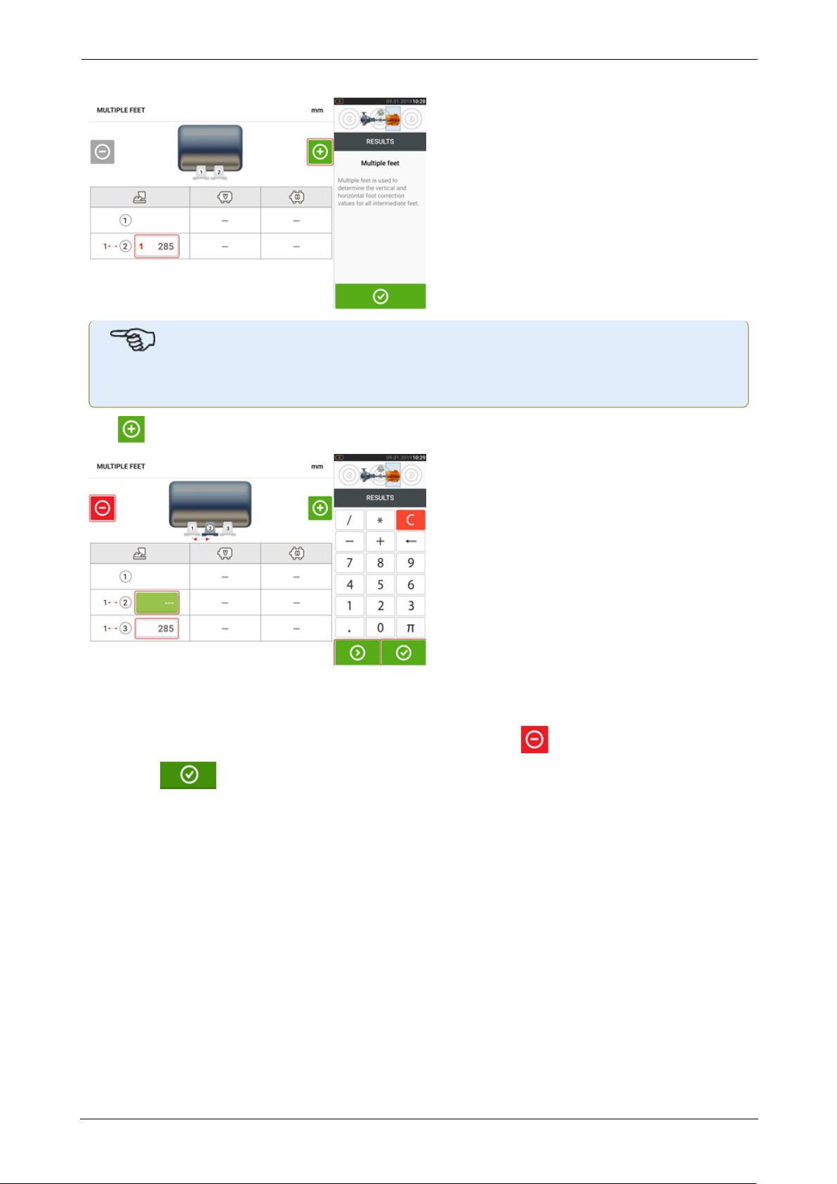
The dimension between the feet may be defined in the 'Multiple feet' screen which is accessed
by tapping the item "Multiple feet".
If already entered, the 'Multiple feet' screen will show the dimension between the front feet
and the back feet [1].
34 Version:2.3
Page 36
On-board help
Note
Machine intermediate feet cannot be displayed in the dimension screen.
Tap to add any intermediate feet.
l The intermediate feet pair is added after the front feet.
l Enter this dimension in the row that appears.
l
If desired, intermediate feet may be deleted by tapping .
l
Tap to exit the 'Multiple feet' screen.
ROTALIGNtouch EX 35
Page 37
On-board help
Laser beam adjustment (sensALIGN 5 EX)
Using sensALIGN 5 laser and sensor
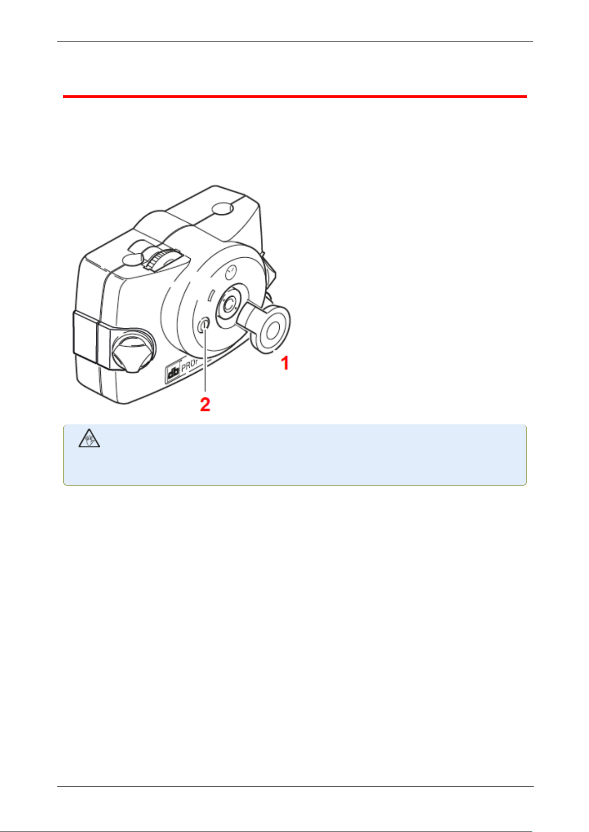
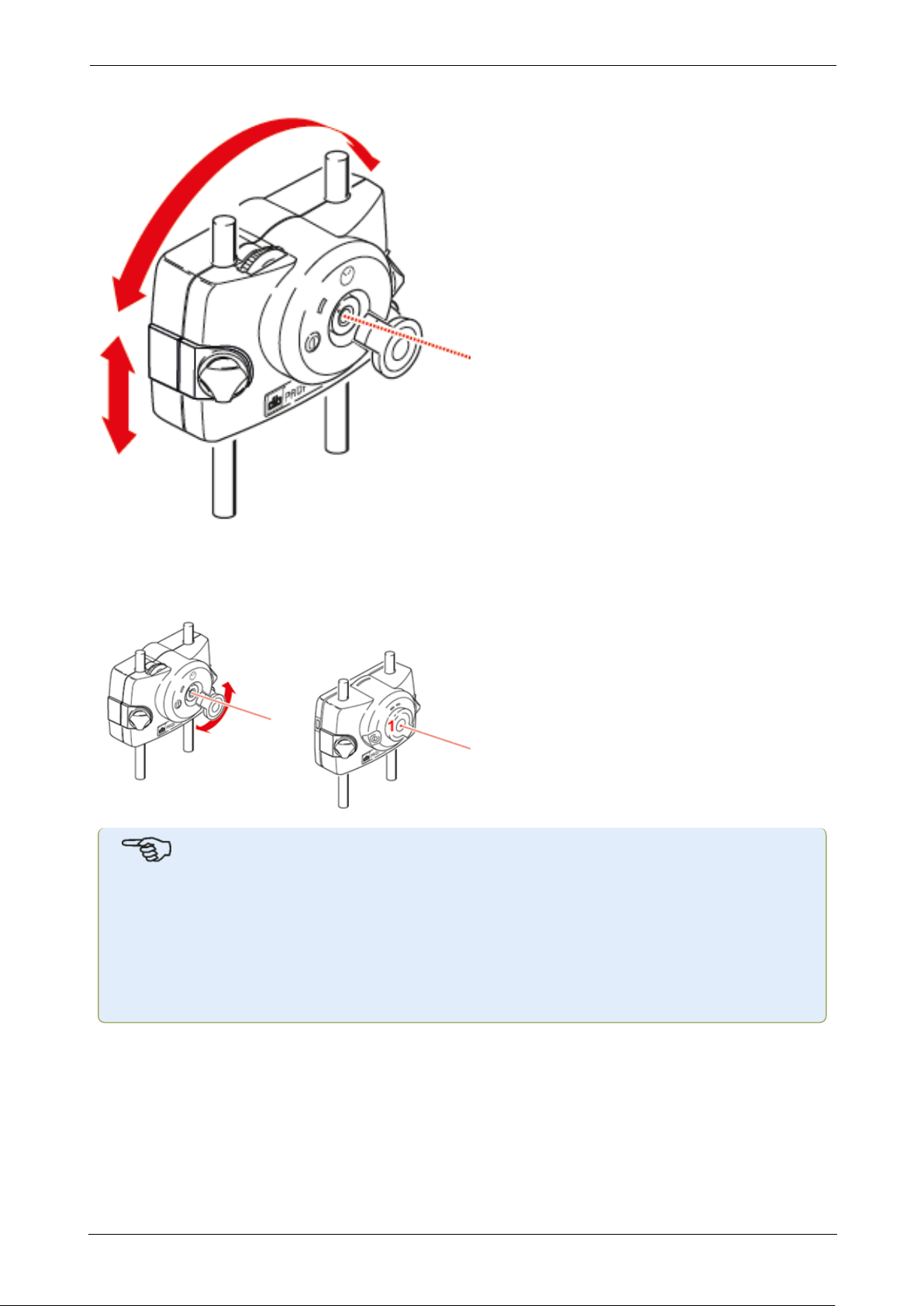
1. Open the laser aperture by lifting and the rotating the dust cap until it rests in its “open” position (1). Switch the laser on by pressing its On/Off push button switch (2). Leave the sensor
dust cap on its “close” position.
WARNING
Do not stare into the laser beam!
2. If the laser and sensor have been roughly positioned to each other during mounting, the
laser beam should strike the sensor dust cap. If the beam be so far off target that it misses
the sensor completely, hold a sheet of paper in front of the sensor to locate the beam and readjust it onto the sensor as follows:
3. Reposition the components until the laser beam strikes the sensor cap:
l vertically: loosen the locking knobs and adjust the height.
l horizontally: loosen the bracket and turn the laser and/or sensor brackets into line with
one another.
36 Version:2.3
Page 38
On-board help
4. Use the adjustment wheels on the laser to center the laser beam on the sensor dust cap (1),
and then open the sensor aperture by lifting and rotating its dust cap until it rests on its “open”
position.
Note
It is highly recommended that before mounting the laser on its bracket, both yellow
adjustment thumbwheels be brought to the approximate center of their travel range.
This will ensure that the beam is emitted from the laser as straight as possible and not
at an angle.
Also make sure both brackets are rotationally aligned to each other.
These precautions will greatly facilitate the beam adjustment process.
ROTALIGNtouch EX 37
Page 39
On-board help
Laser beam adjustment
Laser adjustment wizard
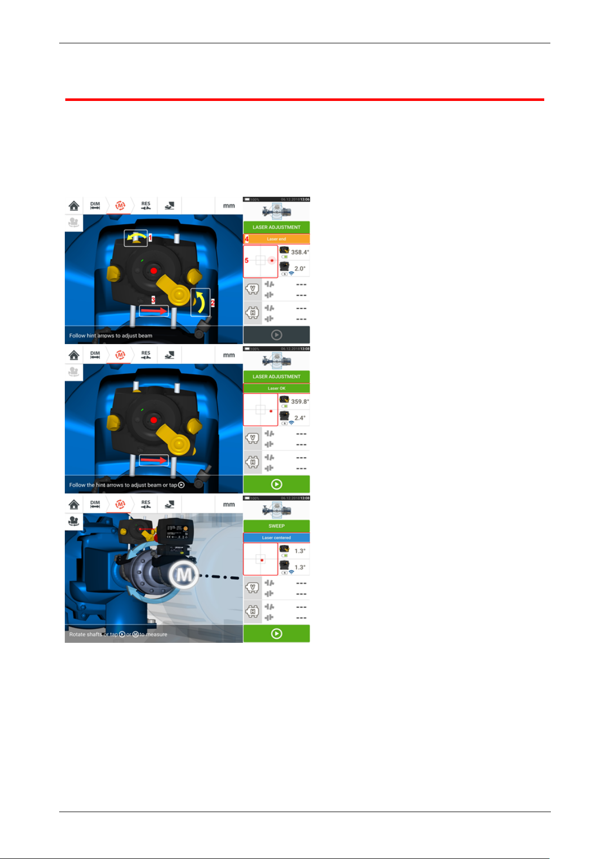
The laser adjustment wizard is the primary laser beam adjustment feature in the touch
device. If the sensor is initialized, and the laser beam is not centered, use the wizard to adjust
the laser beam correctly. The wizard arrows indicate the direction and amount in which movement should take place.
l The wizard arrows next to the laser position thumbwheels (1 and 2) indicate the dir-
ection and magnitude in which the thumbwheels are to be moved in order to adjust the
laser beam correctly.
l The wizard arrows away from the thumbwheels (e.g. 3) indicate the direction and mag-
nitude to move the laser physically for correct adjustment.
l The attained laser beam status is shown in 4.
l 5 shows the position of the laser beam on the position detectors.
38 Version:2.3
Page 40

On-board help
l The wizard arrows decrease in magnitude and occurrence as the laser beam status
improves, disappearing completely once the laser beam is centered.
l Measurement may commence once the laser beam is centered.
It may however be necessary to preadjust the laser beam without using the wizard. In that
case, proceed as follows:
l "Laser beam adjustment (sensALIGN 5 EX)" on page36
ROTALIGNtouch EX 39
Page 41
On-board help
XYView
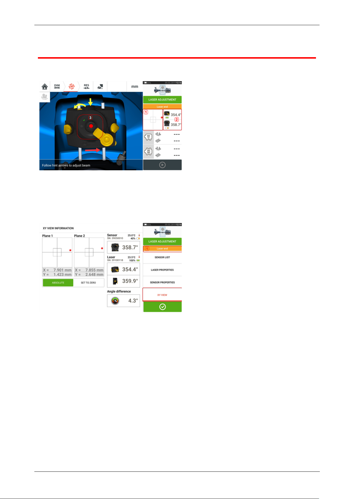
The XY View function is used to facilitate the centering of the laser beam on the two sensor
detector planes before proceeding with measurement.
l Tap the shown detector area (1) to directly access the XY View screen.
l The XY View screen may be accessed using the menu item "XY View" which appears
when the "sensor/laser area" (2) is tapped.
l The XY View screen may be accessed using the menu item "XY View" which appears
when the laser (3) is tapped.
The two sensor detector planes are displayed on the XY View screen. Center the laser beam
dots in both planes using both beam position thumbwheels. In some cases it may be necessary
to move the sensor along the support posts or sideways by loosening the chain type bracket
and slightly rotating it.
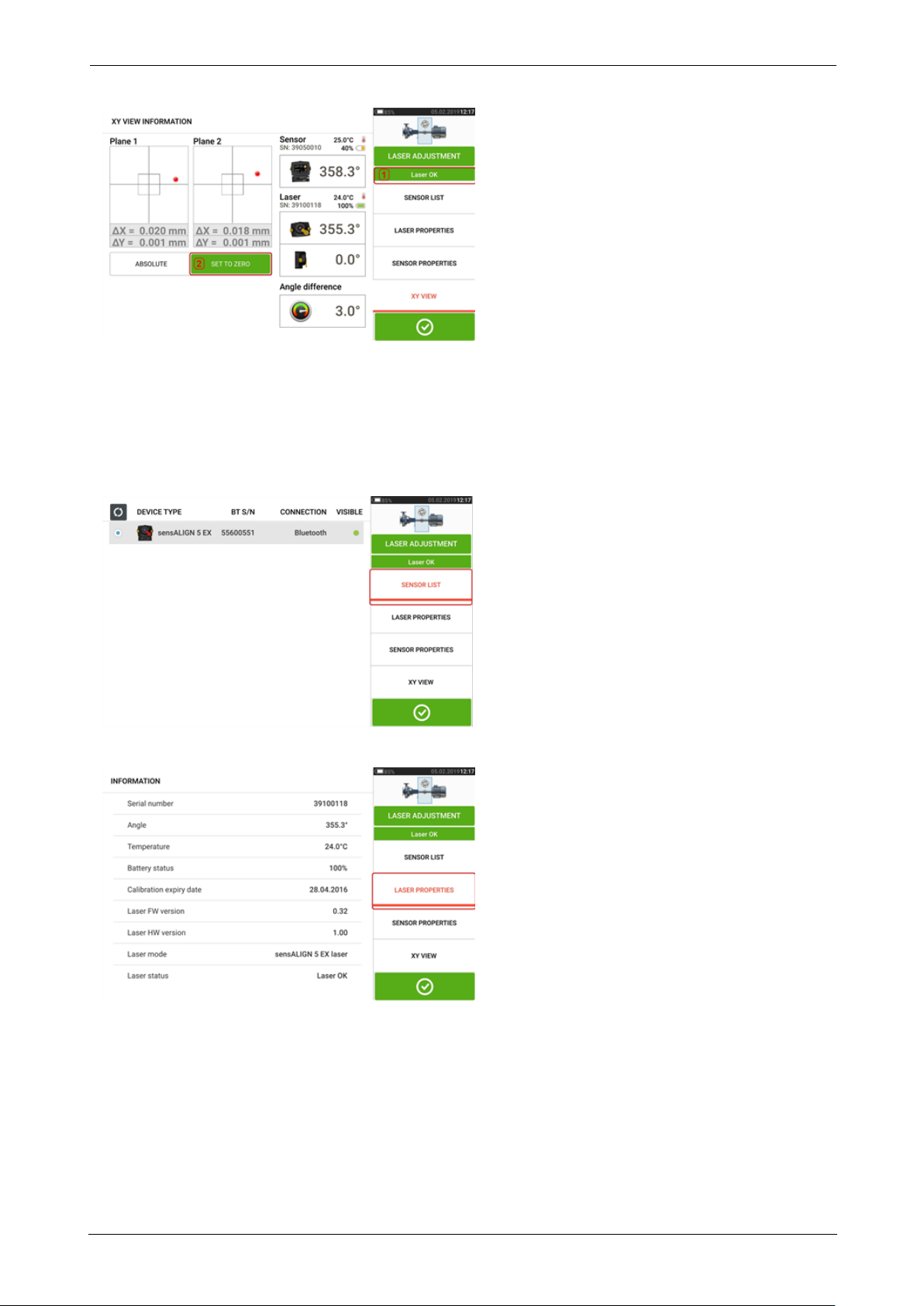
The "Set to zero" function may be used to check the effect of environmental and machinery
vibration on the measurement. Note that the "Set to zero" is active only when the laser beam
status [1] is "OK" or "Centered".
40 Version:2.3
Page 42
On-board help
If the laser beam status is "OK" or "Centered" [1] tap "Set to zero" [2] to set the XYvalues of
the two detector planes to 0,0. These values are then monitored to check the stability of the
values. Tap "Absolute" to return to the absolute values.
Note that the menu items on the screen may be used to display following items:
Sensor list – displays serial number of sensors detected or previously used, as well as type of
connection used for communication.
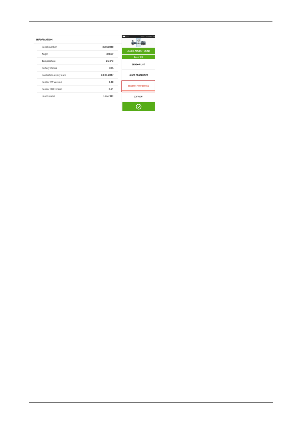
Laser properties – displays detailed information of the laser unit in use
Sensor properties – displays detailed information of the sensor unit in use
ROTALIGNtouch EX 41
Page 43
On-board help
42 Version:2.3
Page 44
On-board help
Initializing sensor
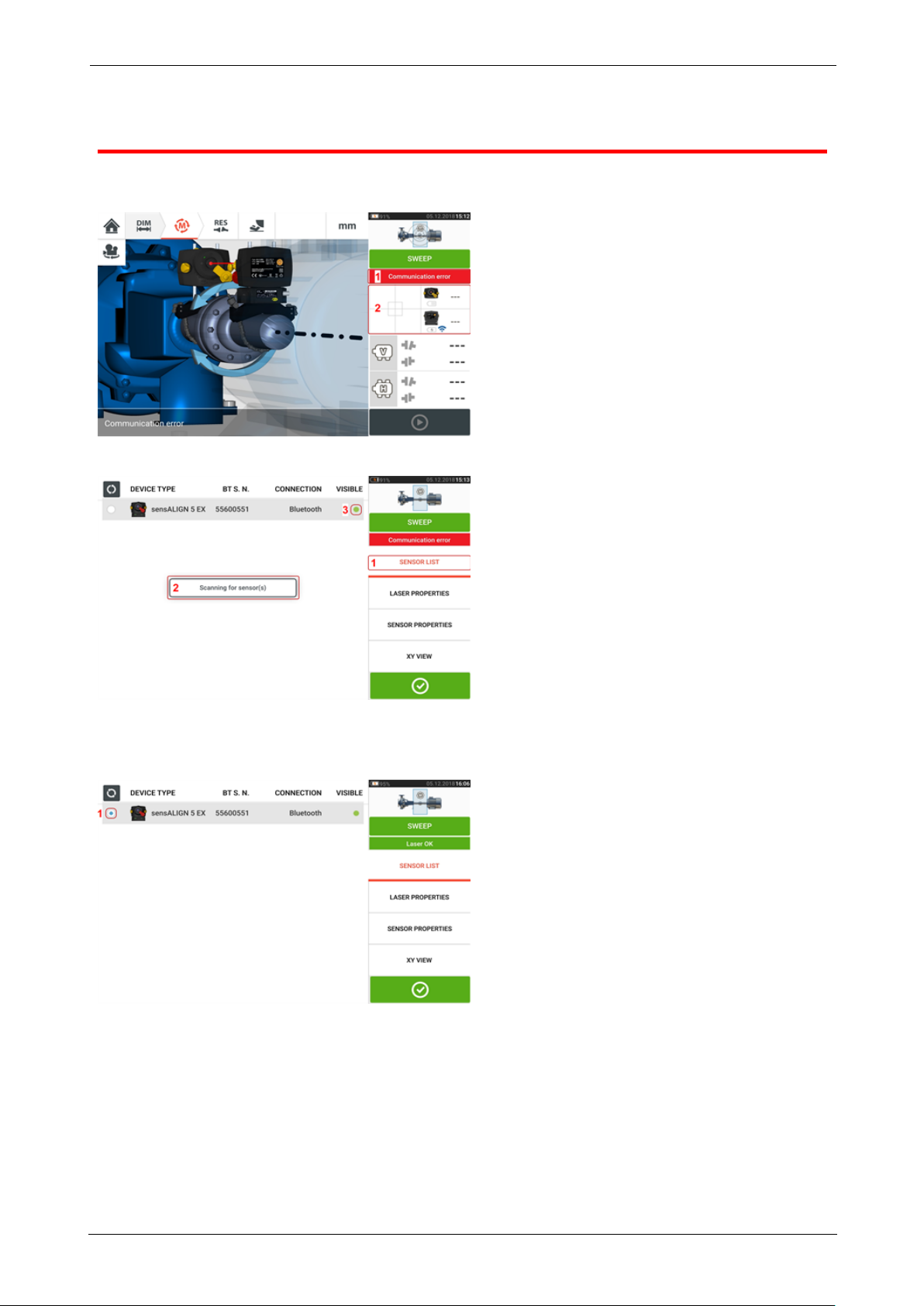
The hint "Communication error" [1] suggests that the sensor has not been initialized although
the laser beam may have been correctly adjusted.
Tap the detector and sensor/laser area [2] to access the menu item 'Sensor list'.
Tap menu item 'Sensor list' [1] to view scanned sensors. The hint 'Scanning for sensor(s)' [2]
appears during the scanning process. As soon as the sensor is detected, it is listed down and a
green bold dot [3] appears next to the detected sensor.
Initialize the sensor by tapping the listed sensor. A bold blue dot [1] signifies that the sensor is
initialized.
ROTALIGNtouch EX 43
Page 45
On-board help
Measurement
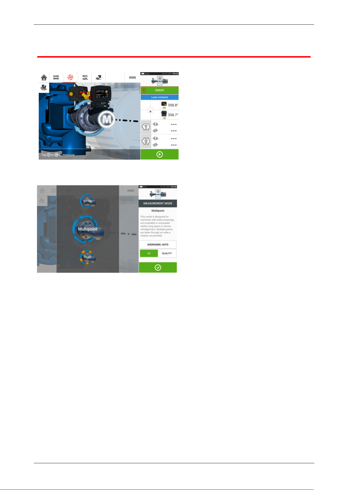
The desired measurement mode is selected while in the measurement screen.
Tap the measurement mode header [1] to access the measurement mode carousel.
Swipe the carousel up or down and select desired measurement mode.
In the above example, Multipoint measurement has been selected. The quality of the measurement may be displayed either as a measurement standard deviation (SD) or measurement
quality factor.
Standard deviation(SD) is the root mean square deviation (mean of the means) of the
measurement points. It describes how closely a group of data points are clustered around the
average of those data points. It is a measure of the measurement calibre. The smaller the SD,
the better the quality of the data collected.
Measurement quality is a factor defined by the following measurement and environmental
criteria: angular rotation, standard deviation of the measurement ellipse, vibration, rotation
evenness, angular rotation inertia, direction of rotation, speed and filter output. The higher the
factor, the better the quality of measurement.
The desired factor is set by tapping the corresponding item. The averaging is set by tapping
the 'Averaging' button.
Averaging
In certain industrial conditions, it may be necessary to increase the number of measurements
(recorded laser pulses) to be averaged when taking readings to attain the desired accuracy.
Particular cases include environments with increased machinery vibration. An increased averaging also improves the accuracy when measuring sleeve bearings, white metal bearings and
journal bearings.
Averaging is possible in ‘point’ measurements such as ‘Multipoint’ and ‘Static mode’.
44 Version:2.3
Page 46
On-board help
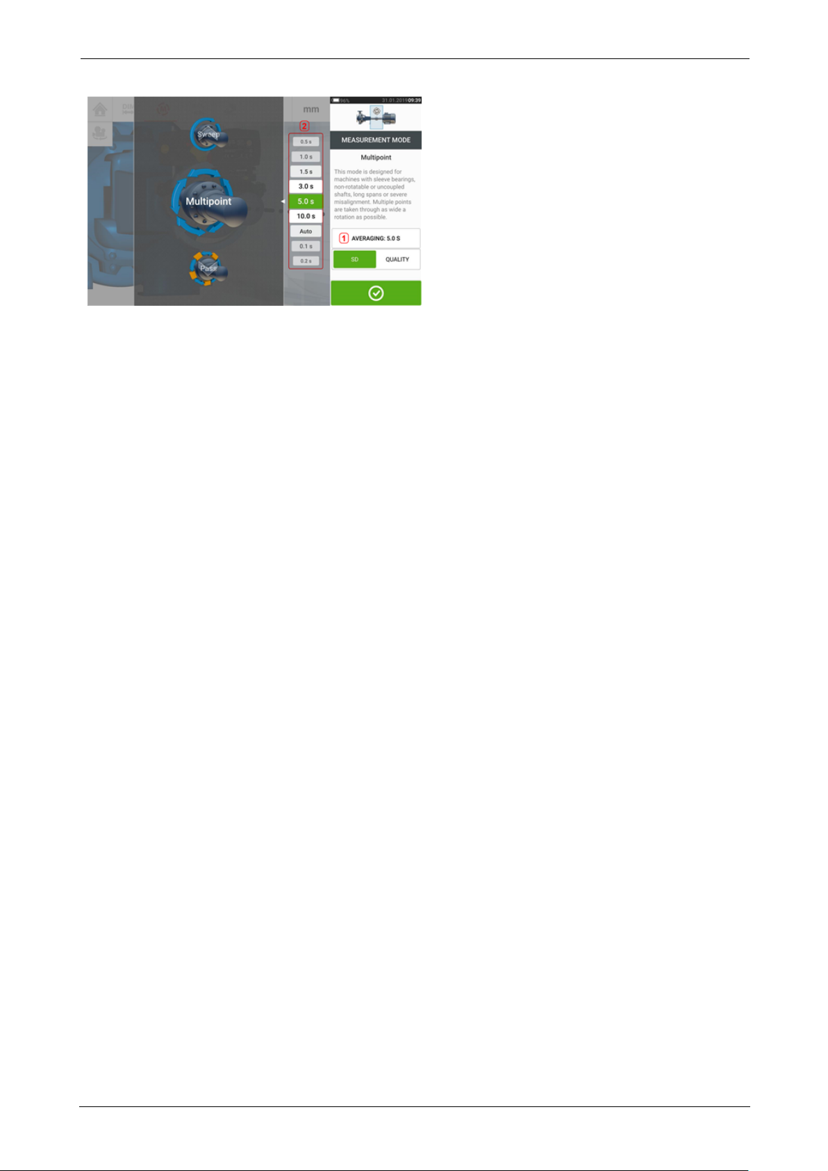
Set the averaging by tapping the 'Averaging' button [1]. A scale [2] used to set the averaging
value appears on the screen. Tap desired averaging value which then appears in the 'Averaging' button [1].
ROTALIGNtouch EX 45
Page 47

On-board help
Measurement modes
The following measurement modes are available for horizontal machine configurations:
l "Continuous Sweep measurement" on page47 –This mode is used to measure standard
coupled machines. The shafts are rotated continuously in machine rotational direction
until acceptable measurement quality is attained.
l "Pass mode" on page55 – Pass measurement mode is used for uncoupled and non-
rotatable shafts (one or both). The laser is rotated past the sensor at different rotational
positions.
l "Multipoint measurement" on page51 – This is the mode used to measure uncoupled
shafts, non-rotational shafts, sleeve bearings [journal (radial) bearings], white metal
bearings , shafts that are hard to turn, shafts with herky-jerky rotation, situations with
long spans or severe misalignment that will readily cause the beam to fall out of range.
l "Static measurement" on page53 – This mode is used to measure vertical mounted
machines.
46 Version:2.3
Page 48
On-board help
Continuous Sweep measurement
This is the default measurement mode and is used to measure standard horizontal coupled
machines.
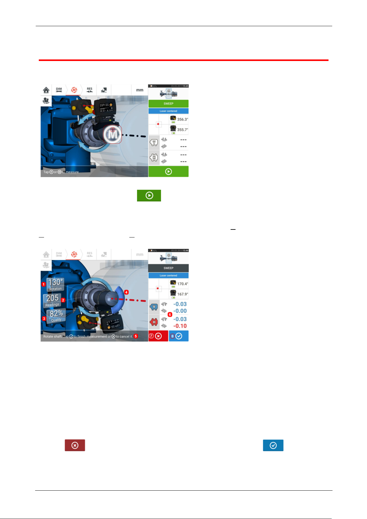
Once the laser beam has been centered, measurement may be started automatically when the
shafts are rotated or by tapping or 'M' (1). Rotate shafts through as wide an angle as
possible.
As shafts are rotated, and depending on the physical condition of the machines, the rotational
arc changes color from red (quality < 40%) to amber (quality >40%<60%) to green (quality
>60%<80%) to blue (quality >80%). Coupling results are displayed as soon as the measurement quality attains 40% (rotational arc turns amber).
l (1) Rotational angle covered by the shafts
l (2) Measurement positions taken
l (3) Measurement quality
l (4) Rotational arc
l (5) Hint
l (6) Coupling results displayed as soon as the measurement quality reaches 40% (rota-
tional arc is orange)
l (7) 'Cancel' icon
l (8) 'Proceed' icon
Tapping the ‘Cancel’ icon discards current measurement. Tapping the ‘Proceed’
icon allows measurement results to be accessed or the measurement repeated.
ROTALIGNtouch EX 47
Page 49
On-board help
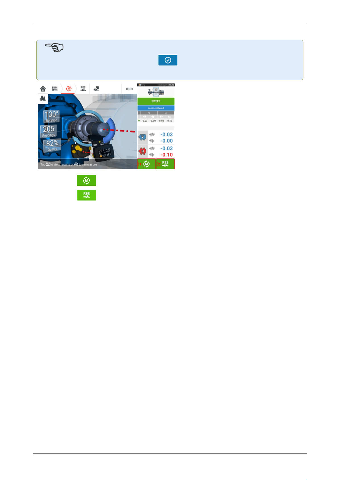
Note that the color of the 'Proceed' icon corresponds to the color of the rotational
arc which denotes the attained measurement quality.
l
(1) Tap to re-measure machines.
l
(2) Tap to view machine foot results.
48 Version:2.3
Page 50
On-board help
Extending measurement range when using Continuous Sweep
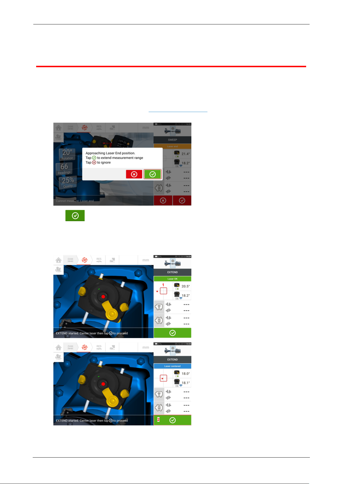
This feature automatically activates the extension of the measurement range while in Continuous Sweep measurement mode. This range extension allows the adjustment of the laser beam
such that it does not miss the detector surface when measuring shafts with gross misalignment or angular misalignment over large distances.
l When taking measurement using Continuous Sweep, and the laser beam approaches
the end of the detector surface, a hint automatically appears on the display.
l
Tap to proceed to extend the measurement range. The program interrupts measurement and switches to the laser beam adjustment screen. The current beam position
is automatically recorded and taken as the starting point for range extension. Follow the
hints on the display and use the two yellow beam position thumbwheels to readjust the
laser beam dot into the detector area target square (1).
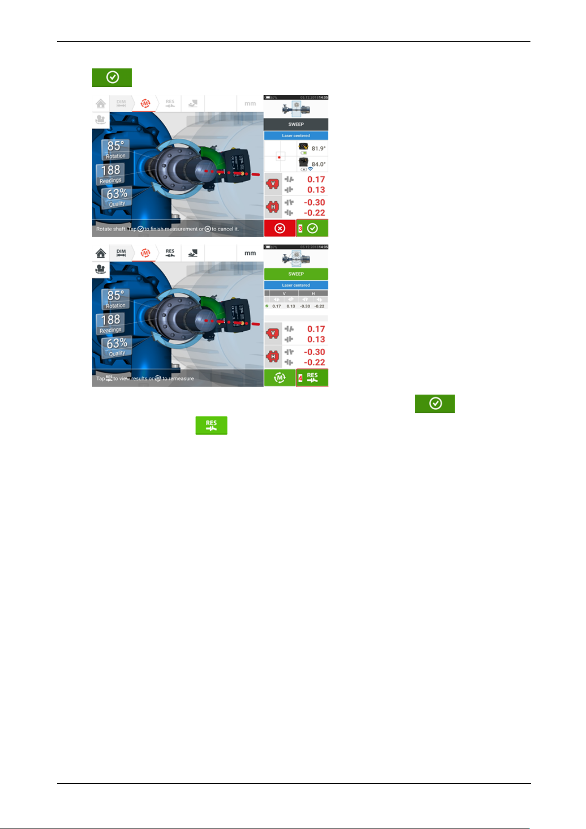
l With the laser beam centered, tap
ROTALIGNtouch EX 49
Page 51
On-board help
(2) then continue with measurement by rotating the shafts further.
l
After rotating the shafts through as wide an angle as possible, tap (3) to pro-
ceed to results, then (4) to view results.
50 Version:2.3
Page 52
On-board help
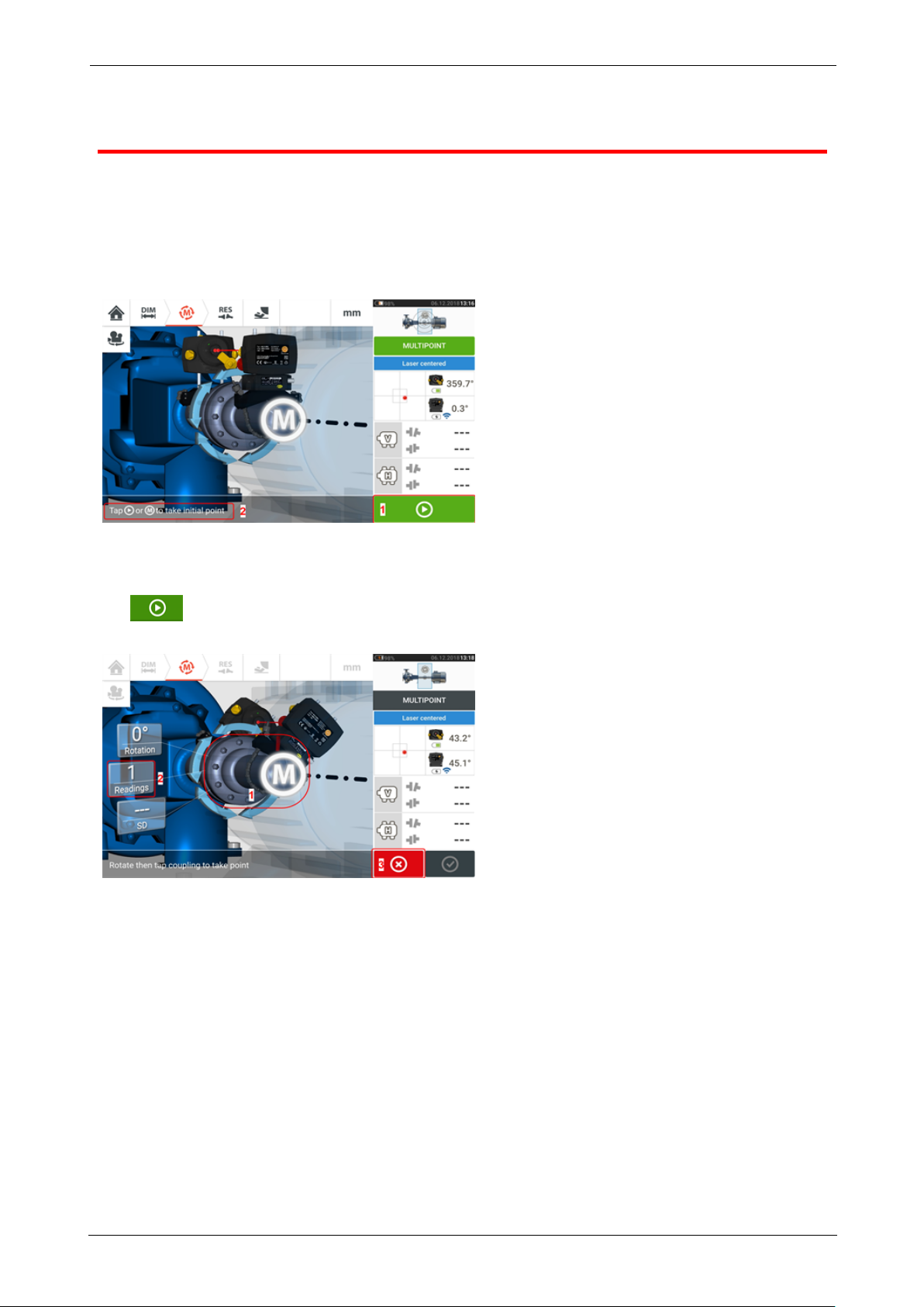
Multipoint measurement
This mode is used to measure shafts which are either difficult to turn continuously or allow
measurement only in certain rotational positions. The method can also be used to measure
uncoupled shafts, nonrotatable shafts, sleeve bearings, white metal bearings and journal
(radial) bearings, shafts that are difficult to turn, shafts with herky-jerky rotation, situations
with long spans or severe misalignment that will readily cause the beam to fall out of range.
If not yet completed, enter machine dimensions, then center laser beam.
l (1) 'Next' icon – tap to take initial measurement point
l (2) Hint to tap 'Next' icon
Tap the 'Next' icon to take the initial measurement point then rotate the shafts in their
normal direction of operation, to the next measurement position.
l (1) Coupling area to be tapped to take next measurement
l (2) Number of points already taken
l (3) 'Cancel' icon – used to cancel current measurement and start new measurement
Tap the coupling area [1] to take the measurement point. Rotate shafts further, taking meas-
urement points by tapping the coupling area [1]. Take as many measurement points through
as wide a rotational angle as possible.
ROTALIGNtouch EX 51
Page 53
On-board help
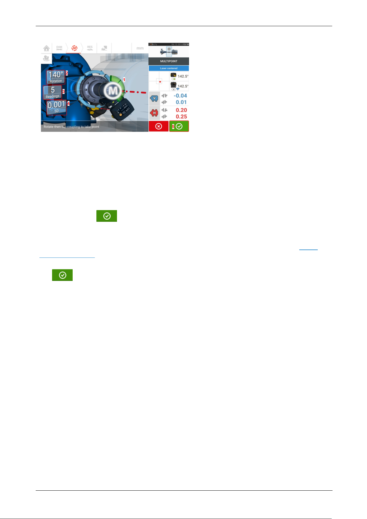
l (1) Rotational arc showing points taken and rotational angle covered by the shafts. The
arc changes color from red [< 60°] -> amber -> green [> 70°]
l (2) Rotational angle completed by the shafts for current measurement
l (3) Number of measurement points taken for current measurement
l (4) Standard deviation attained in current measurement
l (5) 'Proceed' icon – tap to continue to view measurement results
The ‘Proceed’ icon (whose color changes with the rotational arc) becomes active after
three measurement points have been taken.
The horizontal and vertical coupling results are displayed when the shafts are rotated at least
over 60°, and a minimum of three measurement positions are recorded. If however, meas-
urement quality has been selected, the coupling results are displayed when the rotational
arc (1) turns yellow.
Tap the ‘Proceed’ icon to continue to view results or to re-measure.
If required, Live Move may be accessed via the 'Results' screen.
52 Version:2.3
Page 54
On-board help
Static measurement
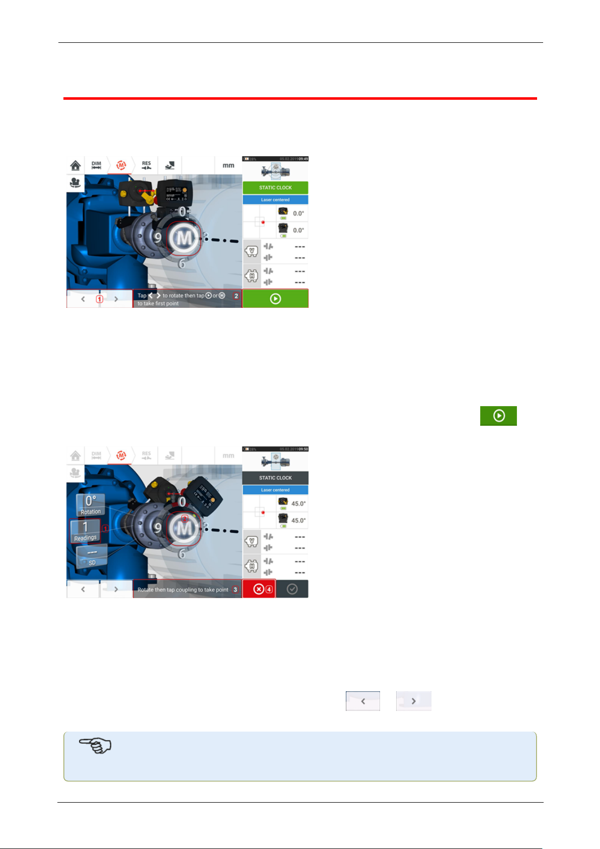
This measurement mode is used for uncoupled shafts, nonrotatable shafts and vertical footmounted or flange-mounted machines.
If not yet completed, enter dimensions then centre laser beam.
l (1) 'The 'left/right' navigation icons are used to position the displayed laser and sensor
at an angular rotation corresponding to the actual position of the components as mounted on the shafts.
l (2) On-screen hint to position displayed laser and sensor then take measurement point
Turn the shafts to any of the eight 45° positions (i.e. 12:00, 1:30, 3:00, 4:30, 6:00, 7:30, 9:00
or 10:30 o’clock position viewed from sensor towards laser). Position shaft as accurately as
possible using either an external inclinometer or protractor. Tap the pulsating M or to
take the first measurement point.
l (1) Number of points already taken (in this example initial point)
l (2) Tap pulsating M to take next measurement
l (3) On-screen hint to position displayed laser and sensor then take measurement point
l (4) 'Cancel' icon – used to cancel current measurement and start new measurement
Rotate shaft to the next measurement position. The displayed laser and sensor must be at the
same angular position as the mounted components. Use or to position the displayed sensor and laser then take next measurement point by tapping the pulsating M [2].
Note
ROTALIGNtouch EX 53
Page 55

On-board help
After taking a measurement point, the displayed laser and sensor move to the next
clock position on the display.
If shaft rotation restrictions hinder the taking of measurements at particular shaft pos-
itions, bypass these using or .
Measurements must be taken in at least three positions over 90°, but more measurements
over a wider angle is recommended.
l (1) Rotational arc showing rotational angle covered by the shafts during measurement.
The arc changes colour from red [< 60°] -> amber -> green [> 70°]
l (2) Rotational angle completed by the shafts for current measurement
l (3) Number of measurement points taken for current measurement
l (4) Measurement quality for current measurement
l (5) 'Proceed' icon – tap to continue to view measurement results
54 Version:2.3
Page 56
On-board help
Pass mode
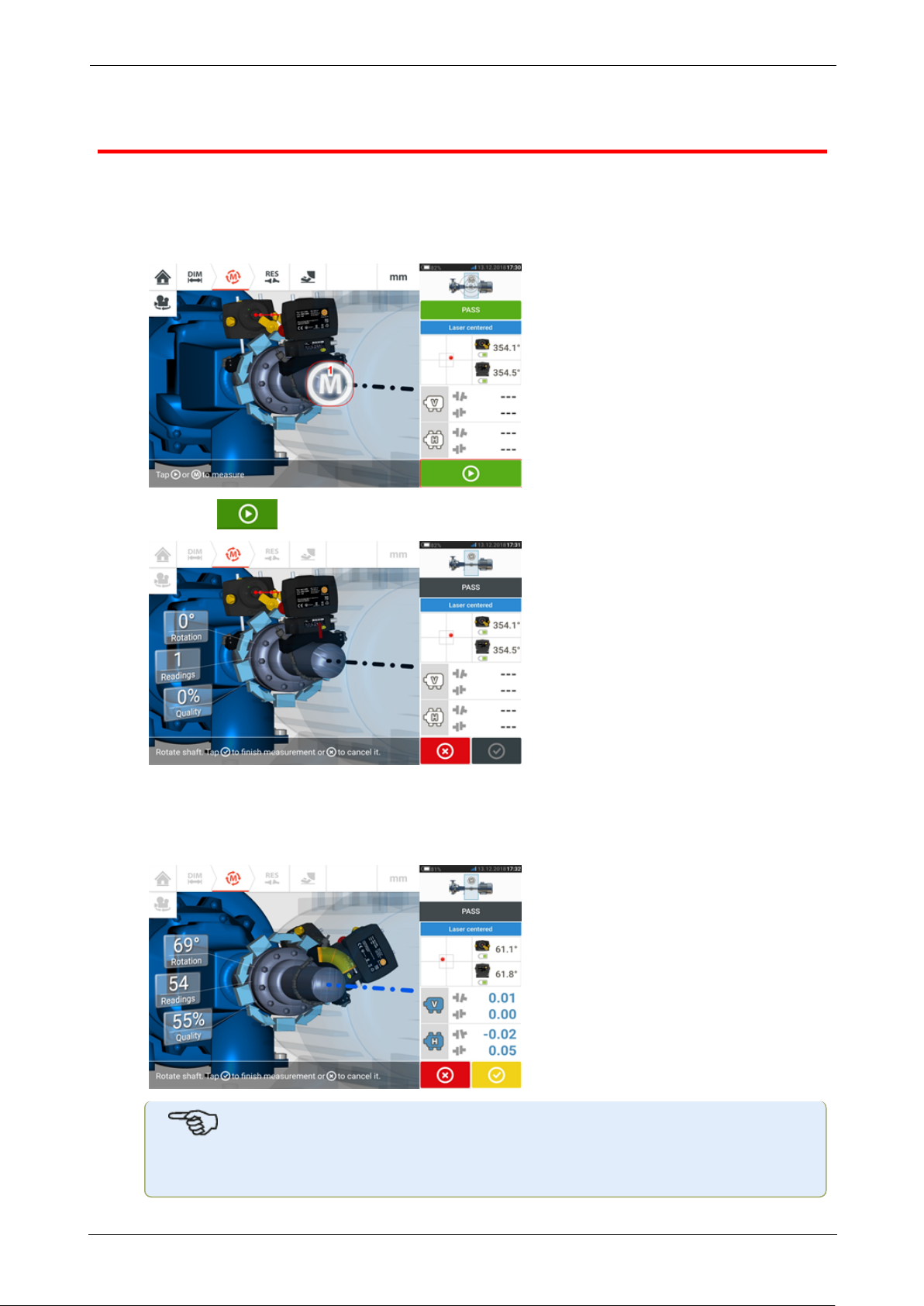
In this mode, the shaft supporting the laser is rotated so that the laser beam strikes the sensor
lens as it passes it. Measurements are taken when the laser beam passes through the middle
sector of the detector.
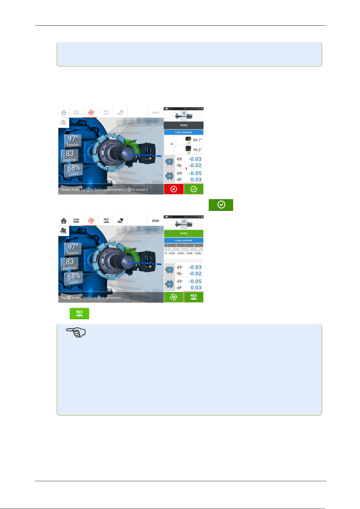
l Center the laser beam. A pulsating M (1) indicates that measurement may be taken.
l
Tap M or to take initial measurement point.
l Rotate the shaft supporting one of the measurement heads (say laser) to the next pos-
ition, then rotate the shaft supporting the other head (say sensor) slowly past the opposite head. Measurement is automatically taken as the laser beam strikes and passes the
sensor detector.
Note
ROTALIGNtouch EX 55
Page 57
On-board help
The sensALIGN 5 sensor laser beam adjustment LED on the front of its housing
blinks green.
l Repeat step 3 taking measurements in as many positions and over as wide an angle as
possible. Coupling results (1) will be displayed if measurements have been taken in at
least three positions over at least 60° rotation.
l
After taking sufficient measurement positions, tap to proceed to results.
l
Tap to view results.
Note
If only one shaft is not easily rotatable while the other can be freely rotated,
always mount the sensor on the nonrotatable shaft (use the magnetic sliding
bracket ALI 2.230). Do NOT mount the laser on the not-easily-rotatable shaft,
even if this means setting up your laser and sensor opposite to the way you normally would for alignment purposes. You can always invert the movable and stationary machines by using the 'rotate machine view' functionality.
Enter all dimensions in accordance with your actual set-up, following the normal
orientation of the laser and sensor in the dimensions screen.
56 Version:2.3
Page 58
On-board help
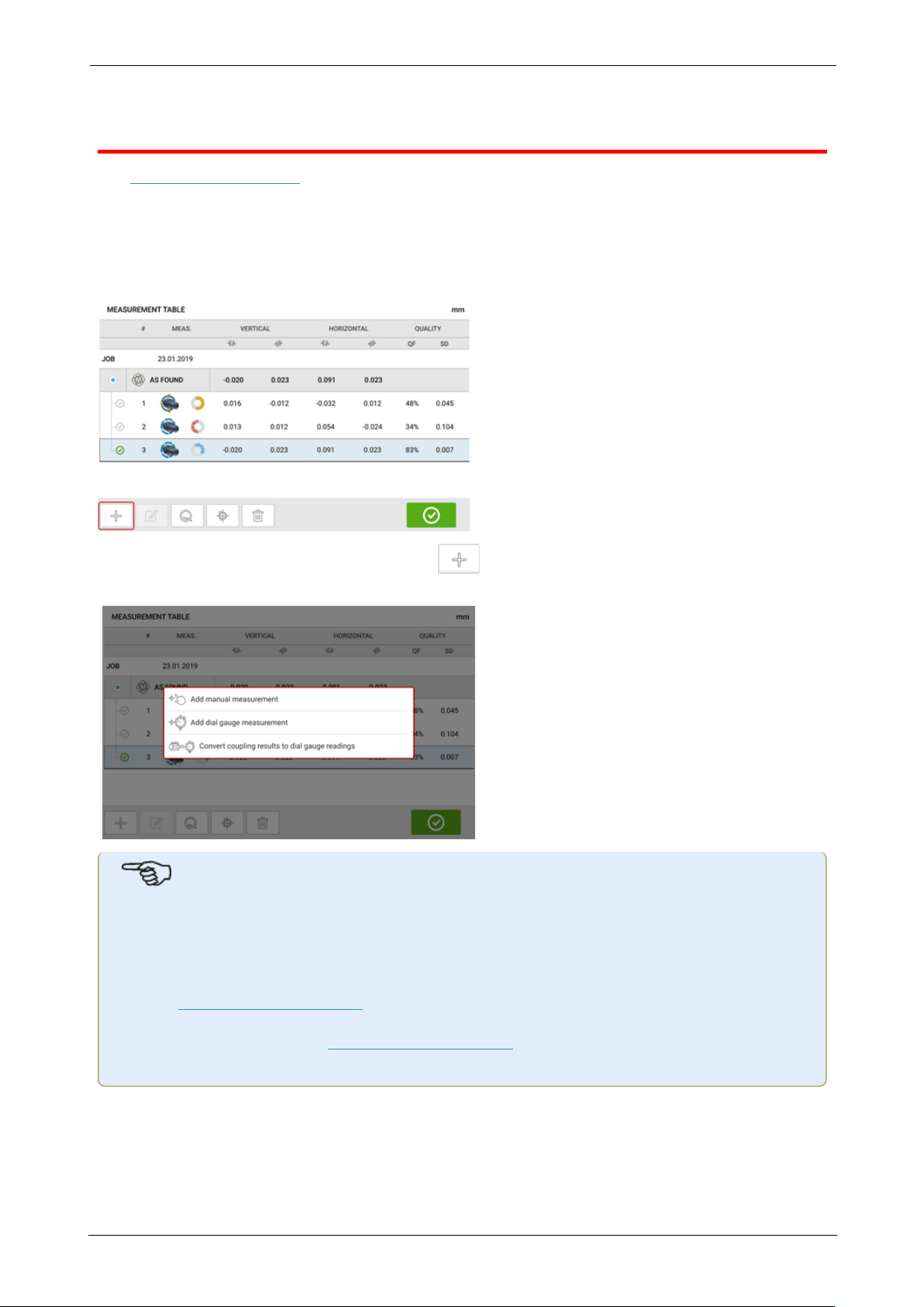
Manual and dial gauge entries
The measurement table may also be used for the following functionalities:
l Entering manual readings
l Addition of a dial gauge measurement and displaying coupling results
l Converting alignment results obtained using sensor-laser measurement into the com-
parable dial gauge readings
When in the measurement table screen, tap . The manual entry and dial gauge functionalities are displayed.
Note
1. If the measurement table is accessed for a new asset without any measurements, the
two options available are "Add manual measurement" and "Add dial gauge measurement".
2.For a new asset, the measurement table may be accessed via the measurement
screen coupling results area by entering the sensor-to-coupling center dimension.
3. For a new asset without sensor-to-coupling center dimension, the measurement table
is accessed by tapping the coupling results area in the results screen.
Entering manual measurement values
With the three items displayed, tap the option "Add manual measurement", then proceed to
enter the coupling values manually.
ROTALIGNtouch EX 57
Page 59
On-board help
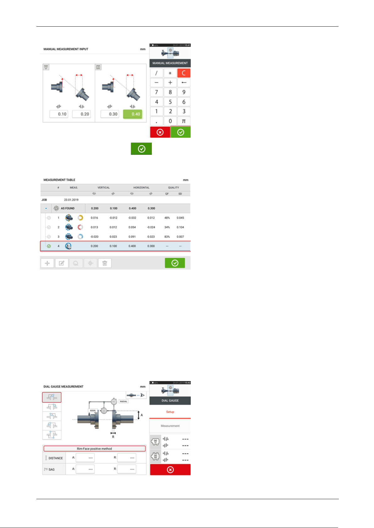
After entering all values, tap to return to the measurement table. The added manual
value appears in the measurement table. The hand symbol next to the entry signifies that it is
a manual entry.
Addition of a dial gauge measurement
With the three items displayed, tap the option "Add dial gauge measurement", then select
desired dial gauge set-up. Five set-up methods are available:
l Rim and face (positive)
l Rim and face (negative)
l Rim and face (reversed)
l Rim and face (negative reversed)
l Reverse indicator
In the following example the rim and face (positive) method has been selected.
58 Version:2.3
Page 60
On-board help
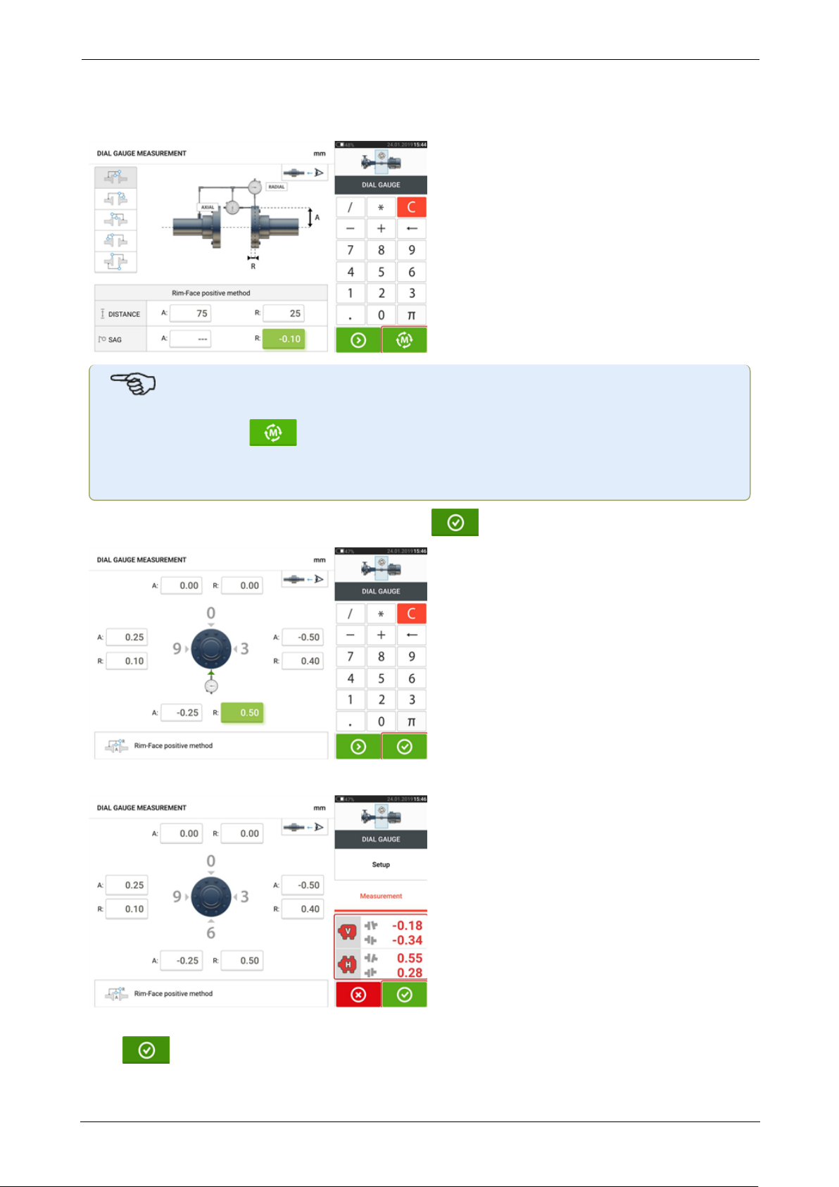
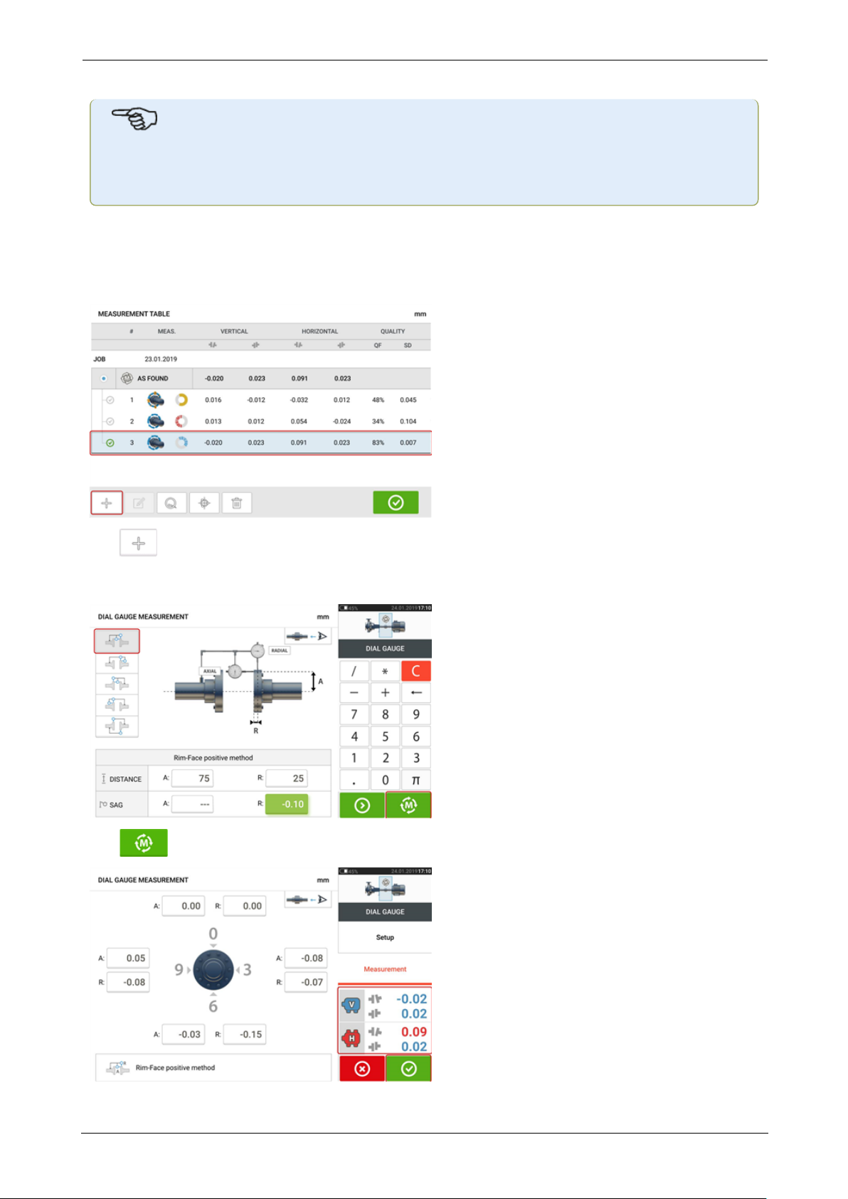
Enter the required dimensions and the amount of bracket sag. In this example, the axial distance A is 75 mm, the radial distance R is 25 mm and the indicator bracket sag R is -0.10 mm.
Note
The "Measure" icon appears as soon as both axial and radial distances have been
entered. It is therefore possible to proceed to measurement without entering the sag
value.
Enter the measured dial gauge readings then tap to display coupling results.
Dial gauge readings are now displayed as coupling results in terms of gap and offset.
The dial gauge measurement is now listed on the measurement table which is accessed by tap-
ping . The dial gauge measurement is identifiable by dial indicator symbol next to the
entry.
ROTALIGNtouch EX 59
Page 61
On-board help
Validity rule
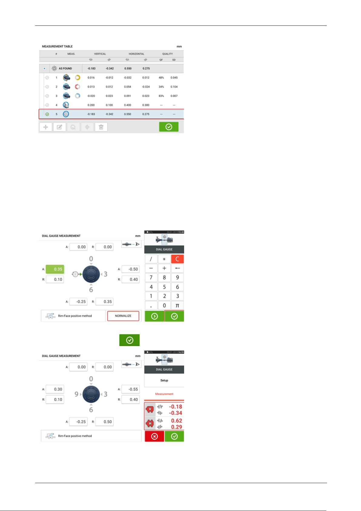
Dial indicator readings are taken at the 12, 3, 6 and 9 o'clock positions. The validity rule states
that when shafts are rotated, the sum of the dial indicator readings at the 12 and 6 o'clock a
positions must equal that of the 3 and 9 o'clock positions.
TOP + BOTTOM = SIDE + SIDE
The validity rule works because readings are taken around the circumference of a circular
object.
If the above is not true, then the measurement should be repeated. The touch device incorporates a functionality used to check the validity rule. If the entered dial gauge measurement
values do not conform to the validity rule, the hint "Normalize" appears on the screen.
Tap "Normalize" to view the adjusted dial gauge values. The coupling results may also be
viewed directly by tapping .
60 Version:2.3
Page 62
On-board help
Note
The adjusted dial gauge values conform to the validity rule. The displayed coupling results are not affected by the validation process.
Convert coupling results to dial gauge readings
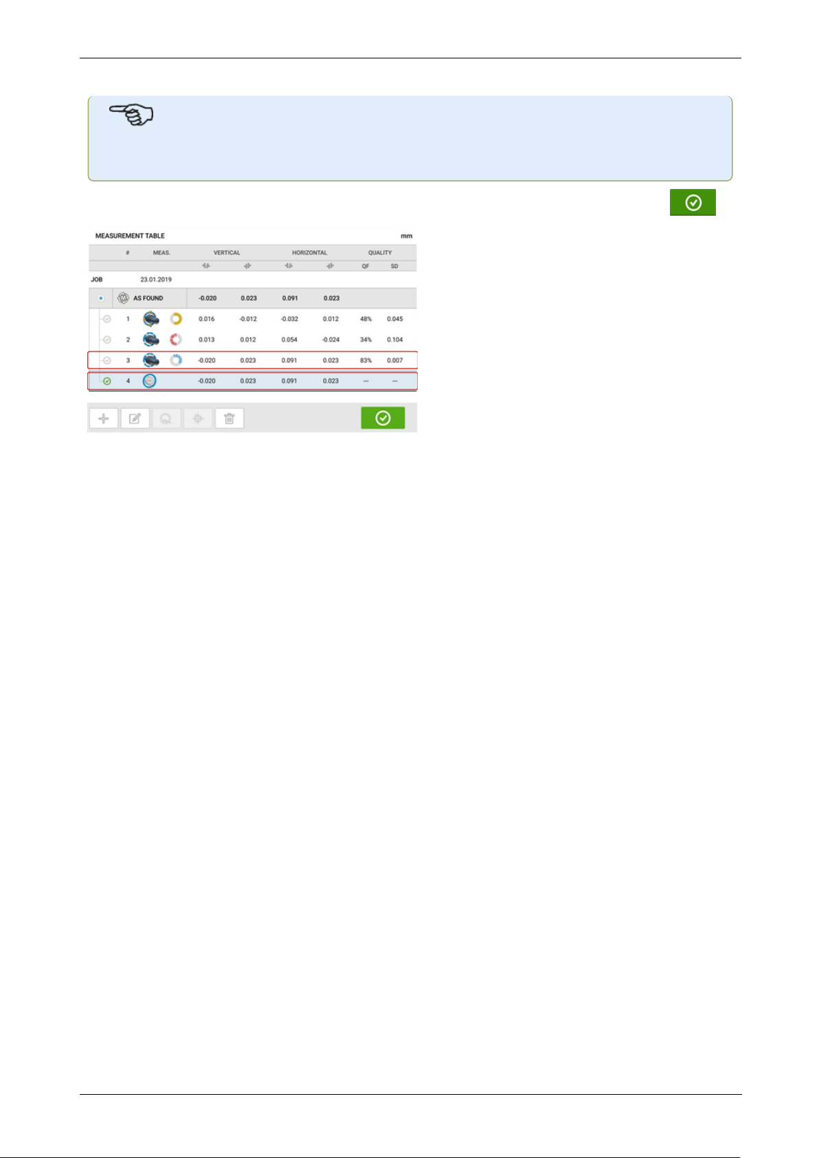
From the measurement table, select measurement whose coupling results are to be converted
to dial gauge values.
Tap then tap the option "Convert measurement to dial gauge".
Select the desired dial gauge set-up, then enter the axial (A) and radial (R) dimensions, and
the amount of bracket sag.
Tap to view the fitting dial gauge values and the corresponding coupling results.
ROTALIGNtouch EX 61
Page 63
On-board help
Note
The calculated dial gauge values conform to the validity rule.
This conversion is now listed on the measurement table which is accessed by tapping .
The converted coupling results correspond to those obtained directly using the touch device.
The dial gauge measurement entry is identified by the dial indicator symbol next to the entry.
62 Version:2.3
Page 64
On-board help
Extend measurement range manually
Measurement range may be extended manually in Multipoint and Static measurement modes.
This range extension allows the adjustment of the laser beam such that it does not miss the
detector surface when measuring shafts with gross misalignment or angular misalignment
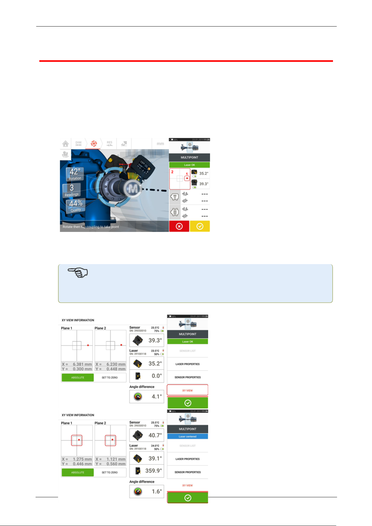
over large distances. During measurement, manual extension is prompted by accessing the XY
view before 'Laser End' is displayed.
l If the laser dot (1)on the display continues to move further away from the center of the
detector screen while rotating shafts to take measurements using Multipoint measurement mode, tap the detector area (2) to access the "XY view" screen.
l After accessing the "XY view", use the two yellow laser horizontal and vertical position
thumbwheels and adjust the laser dots such that they are positioned inside or very close
to the square targets.
Note
During the laser adjustment procedure, avoid readjusting the sensor.
ROTALIGNtouch EX 63
Page 65
On-board help
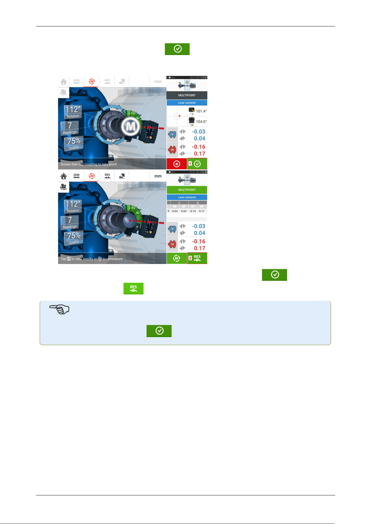
l
With the laser beam centered, tap then continue with measurement by rotating
the shafts further.
l
After rotating the shafts through as wide an angle as possible, tap (1) to pro-
ceed to results, then (2) to view results.
Note
The colour of the proceed icon [ ] depends on the attained measurement quality.
64 Version:2.3
Page 66
On-board help
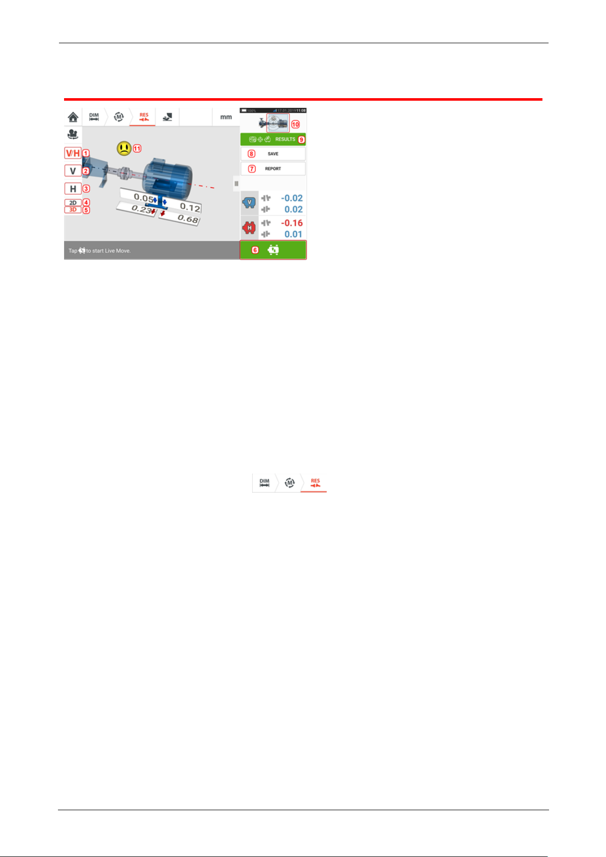
Results
l (1) Displays both horizontal and vertical foot results in 2-D simultaneously
l (2) Used to display vertical foot results only
l (3) Used to display horizontal foot results only
l (4) Used to display foot results in 2-D
l (5) Used to display foot results in 3-D
l (6) Starts Live Move
l (7) Used to generate asset measurement report
l (8) Used to save asset measurements in asset park
l (9) Used to select results mode
l (10) Tapping the slider on the machines icon opens the triple "Train Manager" / "Train
Setup" / "Train Fixation" screen
l (11) Alignment condition tolerance symbol
In the results screen, the three icons – dimensions, measurement and results –
are active and may be used anytime.
The 2D V and H foot results screens show the vertical (V) and horizontal (H) foot positions
respectively.
The colors of the bold arrows next to the feet correction values are directly related to the coupling alignment condition as follows:
Blue – excellent [foot should not be moved]
Green – good [if possible foot should remain unaltered]
Red – poor [foot requires moving to attain a better alignment condition]
ROTALIGNtouch EX 65
Page 67
On-board help
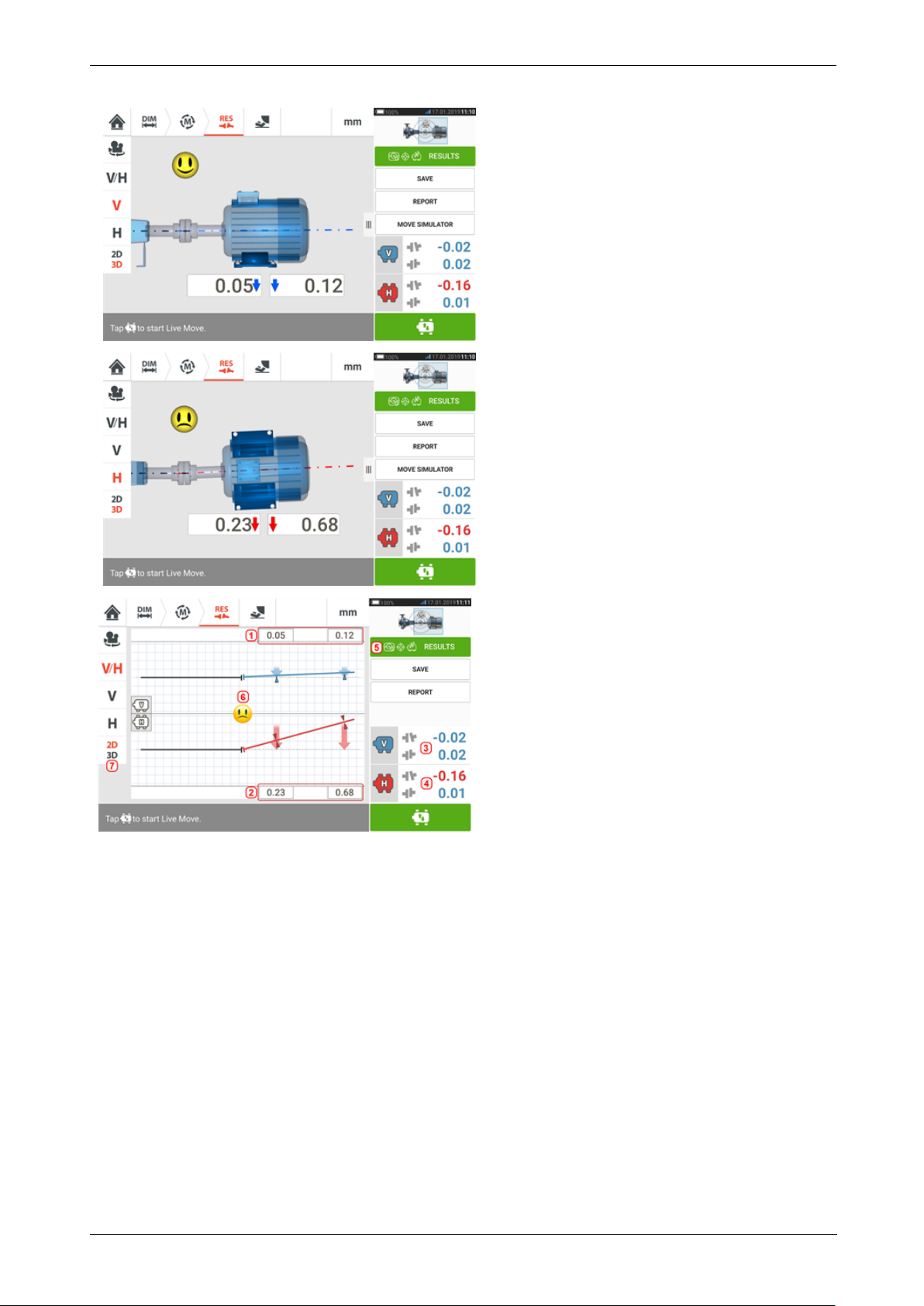
l (1) Vertical foot position results
l (2) Horizontal foot position results
l (3) Vertical coupling results
l (4) Horizontal coupling results
l (5) Selected results mode
l (6) Alignment condition tolerance symbol
l (7) Horizontal and Vertical foot results in 2D
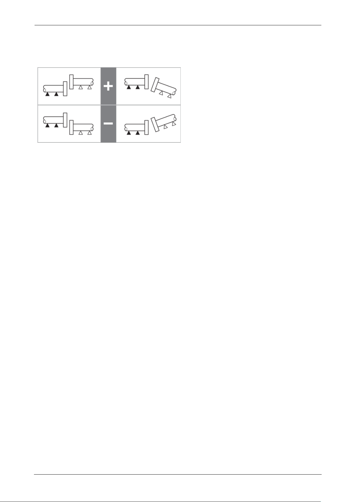
Sign convention
Coupling gap is positive when open at top or side away from viewer. The viewer is considered
to be standing in front of the machines as they appear on the display.
Offset is positive when the right shaft axis is higher than the left shaft axis or further away
from the viewer than the left axis.
66 Version:2.3
Page 68
On-board help
Both vertical and horizontal results show the foot position relative to the centerline of machine
designated stationary. Positive values indicate that machine is upwards or away from viewer.
Negative values indicate that machine is downwards or towards the viewer.
ROTALIGNtouch EX 67
Page 69
On-board help
Multiple feet results
Foot corrections
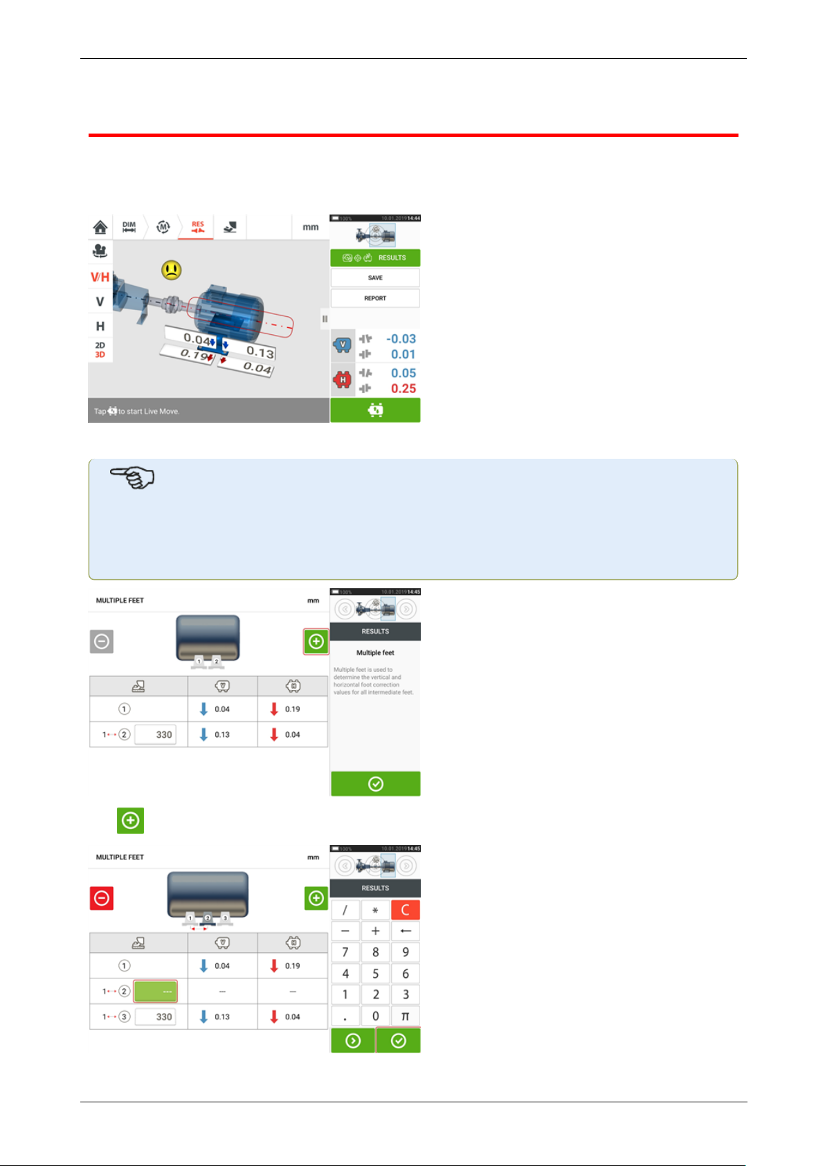
Foot corrections in a multiple feet machine are viewed from the result screen.
Tap the machine centerline to access the results multiple feet screen.
Note
If the machine intermediate feet were already defined within machine properties, then
the foot corrections for the intermediate feet will be displayed. In the following
example, the intermediate feet has not been defined.
Tap to add any intermediate feet.
68 Version:2.3
Page 70
On-board help
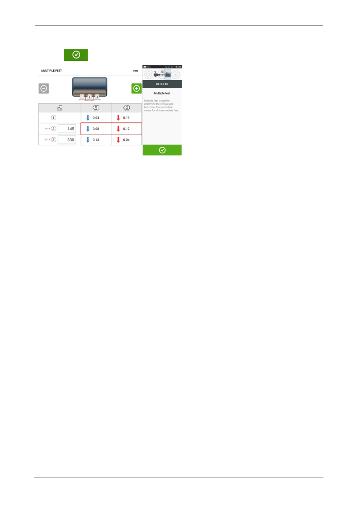
Enter the diemnsion between the front feet and the intermediate feet in the row that appears
then tap .
The foot correction values for the intermediate feet appear in the corresponding row.
ROTALIGNtouch EX 69
Page 71
On-board help
Tolerances
Alignment quality is evaluated through comparison with tolerances based upon entered
machine dimensions and RPM.
The tolerance ranges are compiled as tables according to type of coupling, coupling format,
and diameter (for the gap value) as well as RPM. When the coupling type is spacer, the tolerance table values are determined by the length of the spacer shaft and the RPM.
For cardan, tolerances are available for 1/2° and 1/4° limits.
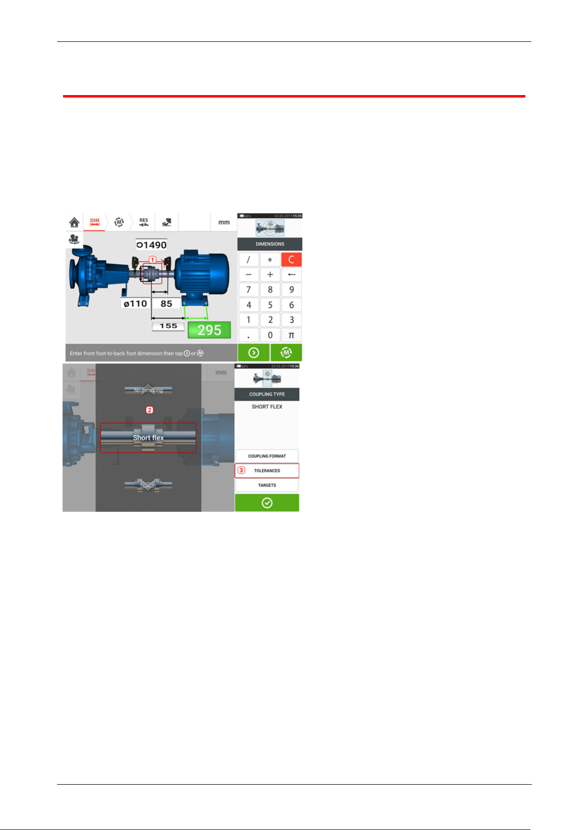
Tolerances are accessed via the dimensions screen.
Tap the coupling (1), then use the carousel that appears to select the desired coupling type
(2). Tap 'Tolerances' (3) to access the coupling tolerance table.
Available tolerance tables
The available tolerance tables are based on machine operating frequency.
70 Version:2.3
Page 72
On-board help
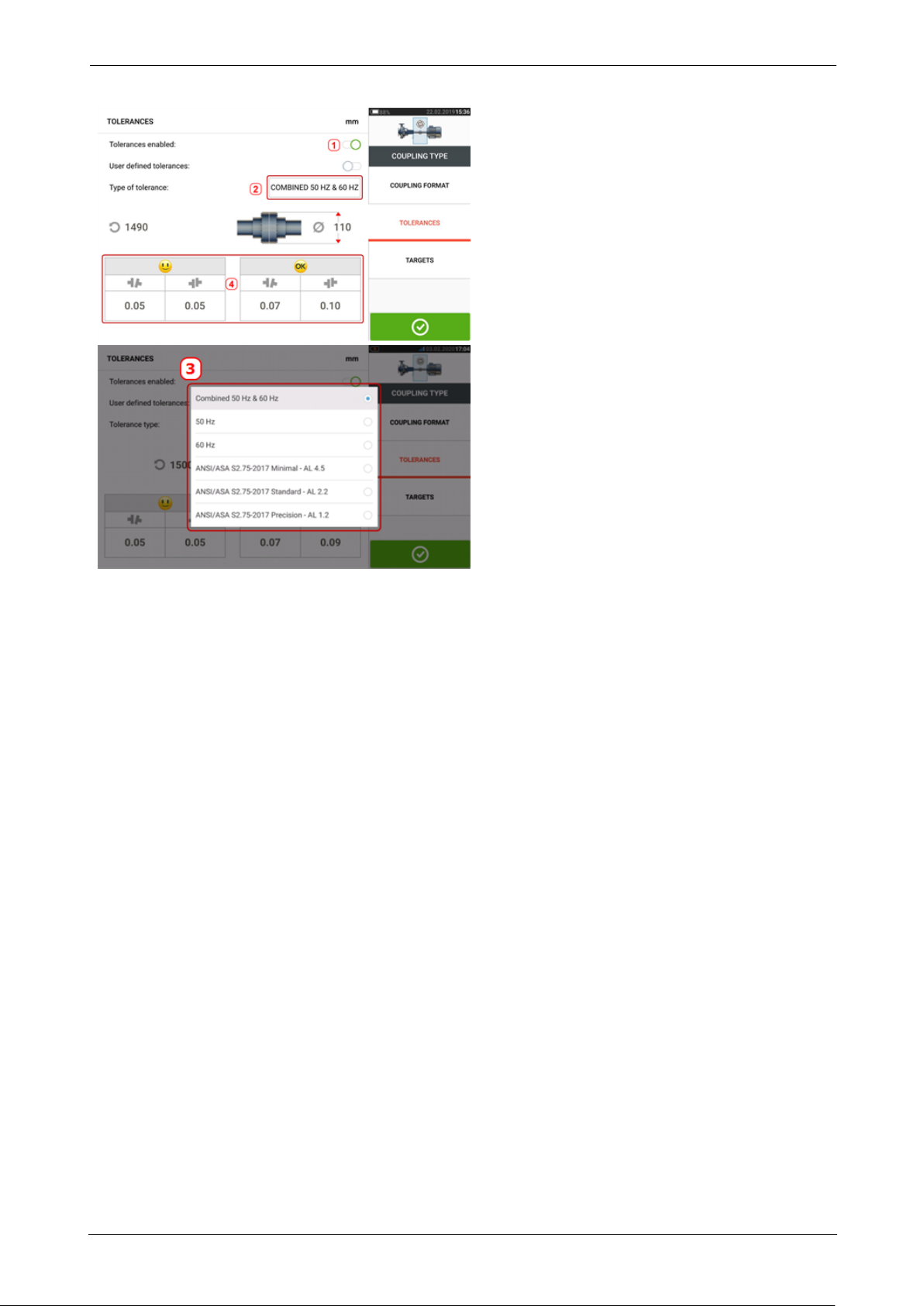
Swipe the icon (1) to the right to enable tolerances. Tap (2) to select desired type of tol-
erance. A pop-up menu (3) appears showing available tolerances. Tap desired type to display
the corresponding tolerance table (4).
ANSI standard specification tolerances
The Acoustical Society of America (ASA) developed shaft alignment tolerances for both short
flex and spacer couplings on standard rotating machinery. These tolerances are an approved
American National Standards Institute (ANSI) specification, and are grouped into three tiers
(minimal, standard and precision).
ROTALIGNtouch EX 71
Page 73
On-board help
User defined tolerances
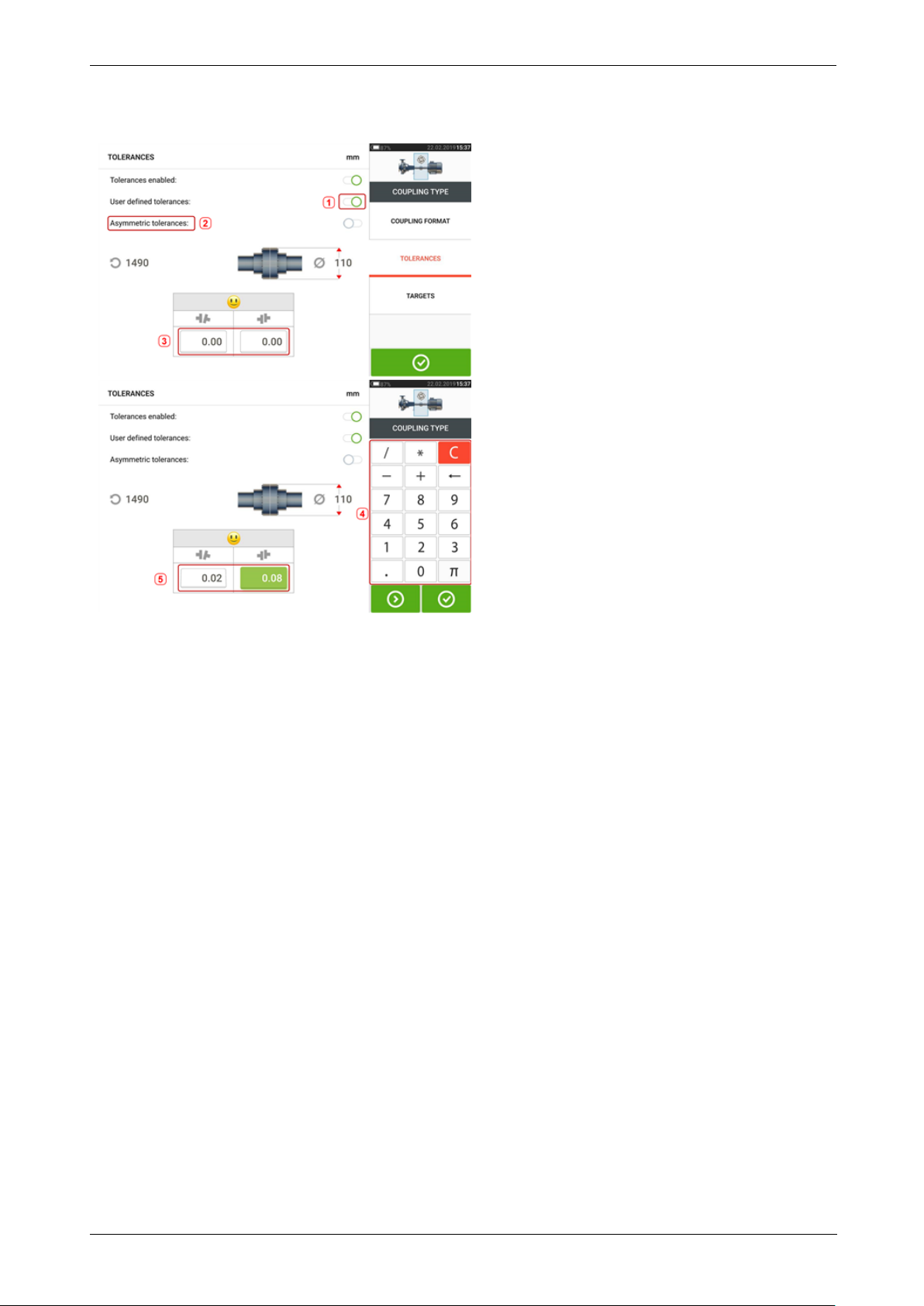
Swipe the icon (1) to the right to enable user defined tolerances. Asymmetric tolerances (2)
can be activated only when user defined tolerances are enabled. In asymmetric tolerances,
the tolerance values for the two coupling planes are not the same. Tap (3) to edit user defined
tolerances using the onscreen keyboard (4). The edited values are then displayed (5).
72 Version:2.3
Page 74
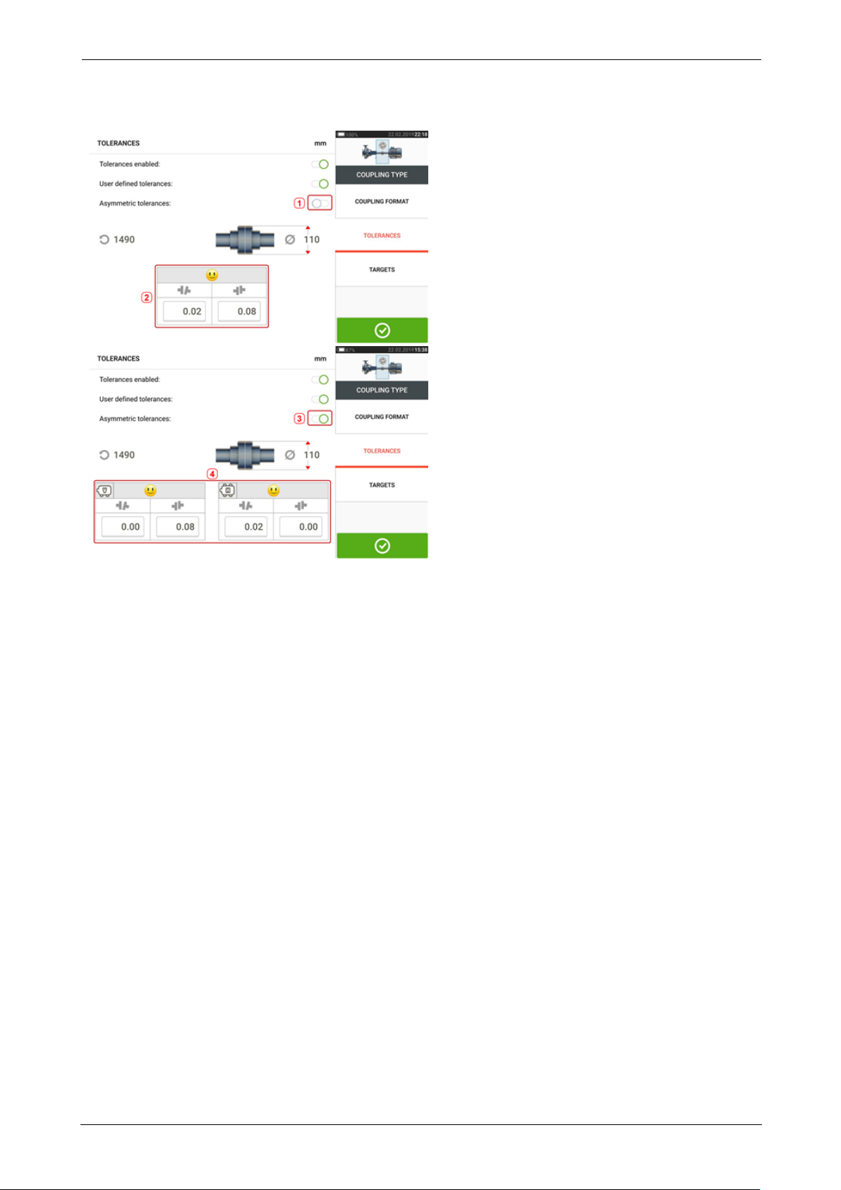
Asymmetric and symmetric tolerances
On-board help
When asymmetric tolerances have not been enabled (1), the displayed specified tolerances
(2) are symmetric. The gap and offset tolerances for both horizontal and vertical planes are
identical.
If asymmetric tolerances are enabled (3) all four specified values are displayed (4).
ROTALIGNtouch EX 73
Page 75
On-board help
Tolerance table based on coupling format
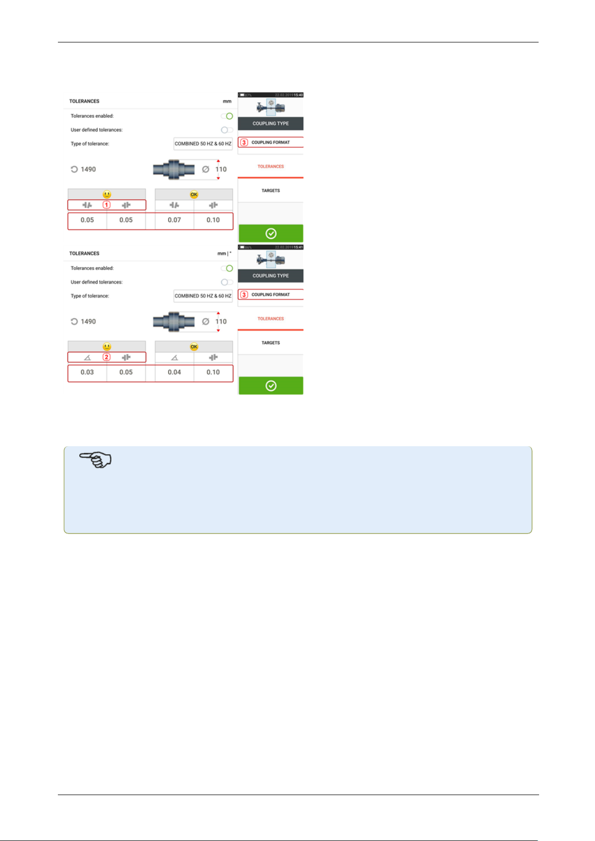
For the same type of tolerance, RPM, and coupling diameter, the tolerances value differ
according to the coupling format selected. Coupling format (1) is gap/offset for short flex coupling, and (2) is angle/offset for short flex coupling. Change coupling format by tapping 3.
Note
There are no tolerance tables for consolidated spacer shaft coupling formats. Consolidated formats consider the spoolpiece or jackshaft as an extension of either the
right or left shaft.
74 Version:2.3
Page 76
On-board help
Live Move screen
Note
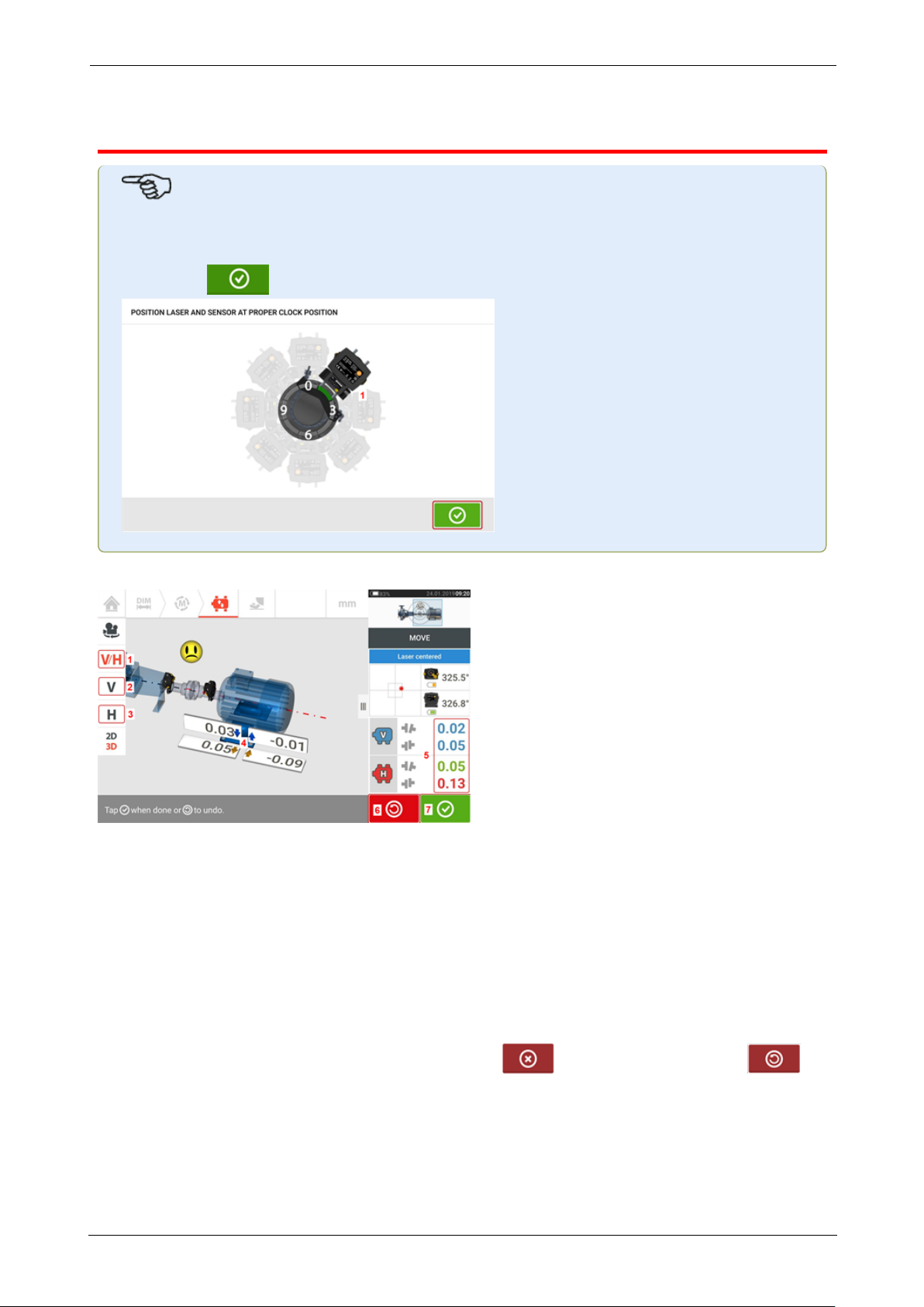
If Static measurement mode is selected, the Live Move screen is accessed only after the
desired 45° clock position (1) of the sensor and laser has been selected and confirmed
by tapping in the position selection screen that appears.
Live Move is monitored in both horizontal (H) and vertical (V) planes simultaneously.
l (1) Tap the 'V/H' icon to follow both vertical and horizontal foot corrections sim-
ultaneously
l (2) Tap the 'V' icon to follow the vertical foot corrections
l (3) Tap the 'H' icon to follow the horizontal foot corrections
l (4) Arrows indicate direction and magnitude to move machine feet
l (5) Tolerance coded gap and offset coupling values
l (6) Tapping the 'Undo' icon allows user to re-measure or start Live Move afresh
l (7) Tapping the 'Proceed' icon allows user to re-measure or start Live Move afresh
Once Live Move has been detected, the 'Cancel' icon replaces the 'Undo' icon .
ROTALIGNtouch EX 75
Page 77
On-board help
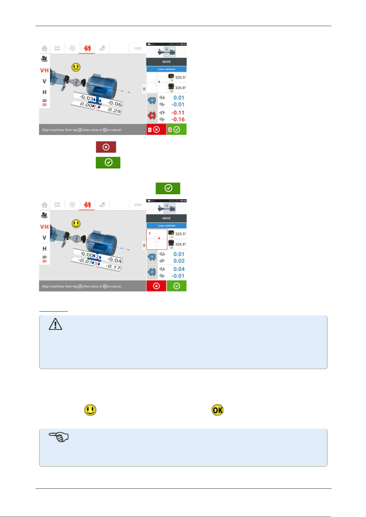
l
(1) Tapping the 'Cancel' icon prompts the 'Cancel Move' hint.
l
(2) Tapping the 'Proceed' icon allows Live Move to be started afresh or the
machines be remeasured.
If the laser beam is centered, tapping starts Live Move automatically.
If the laser beam is not centered, tap the detector area on the screen [1] to access the
XYView.
CAUTION
Do NOT attempt to move the machine using heavy sledgehammer blows. This can cause
bearing damage, and also produce inaccurate Live Move results. Jack bolts on the feet
or other mechanical or hydraulic devices are recommended for moving machines.
Correct the alignment condition by shimming and moving the machines laterally following the
bold vertical [2] and horizontal [3] arrows. The color coded bold arrows signify the attained
coupling tolerance as follows: Blue (excellent condition); Green (good condition) and Red
(poor condition). Machines should be moved to within acceptable tolerances indicated by a
happy smiley [ ] (excellent tolerance) or an OK icon [ ] (acceptable tolerance) while
observing shaft alignment best practices.
Note
The system monitors both horizontal and vertical Live Move concurrently. If the vertical
76 Version:2.3
Page 78
On-board help
view (V) is selected when the function Live Move function is started, only the vertical
condition will be displayed (although both planes are being monitored simultaneously).
Likewise, if the horizontal view (H) is selected, then only the horizontal condition will be
displayed (but both planes monitored simultaneously).
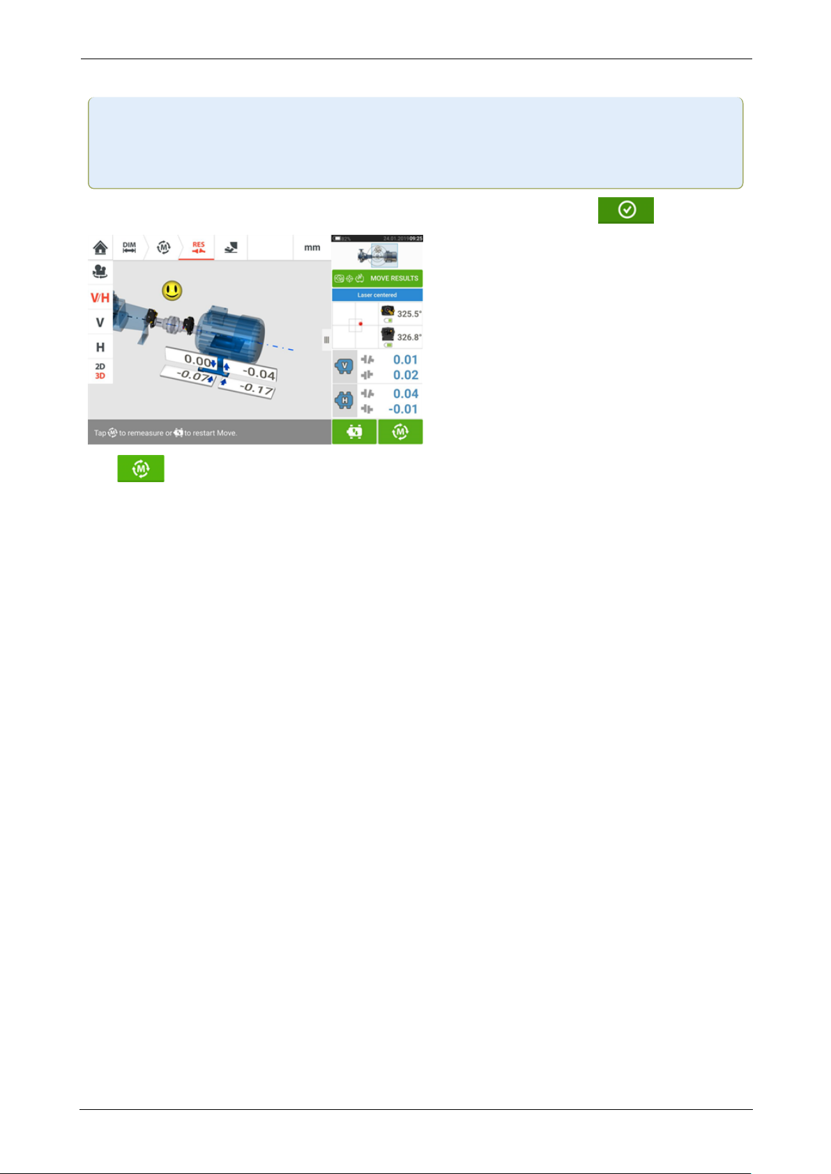
After moving machines to within tolerance, tighten the foot bolts then tap .
Tap to remeasure and verify the Live Move results, and confirm new alignment condition.
ROTALIGNtouch EX 77
Page 79
On-board help
Move simulator
As the name suggests, the Move simulator is used to simulate shim values and horizontal
movement corrections that are required to correct the alignment condition. The simulator
takes into account the shim thickness available and the amount by which the machines can be
physically moved.
Note
Move simulator can be used on a single plane only (either Vertical or Horizontal). Simulation is possible for the current (or "as left") measurement only. And the simulation
may be carried out in 2D or 3D view.
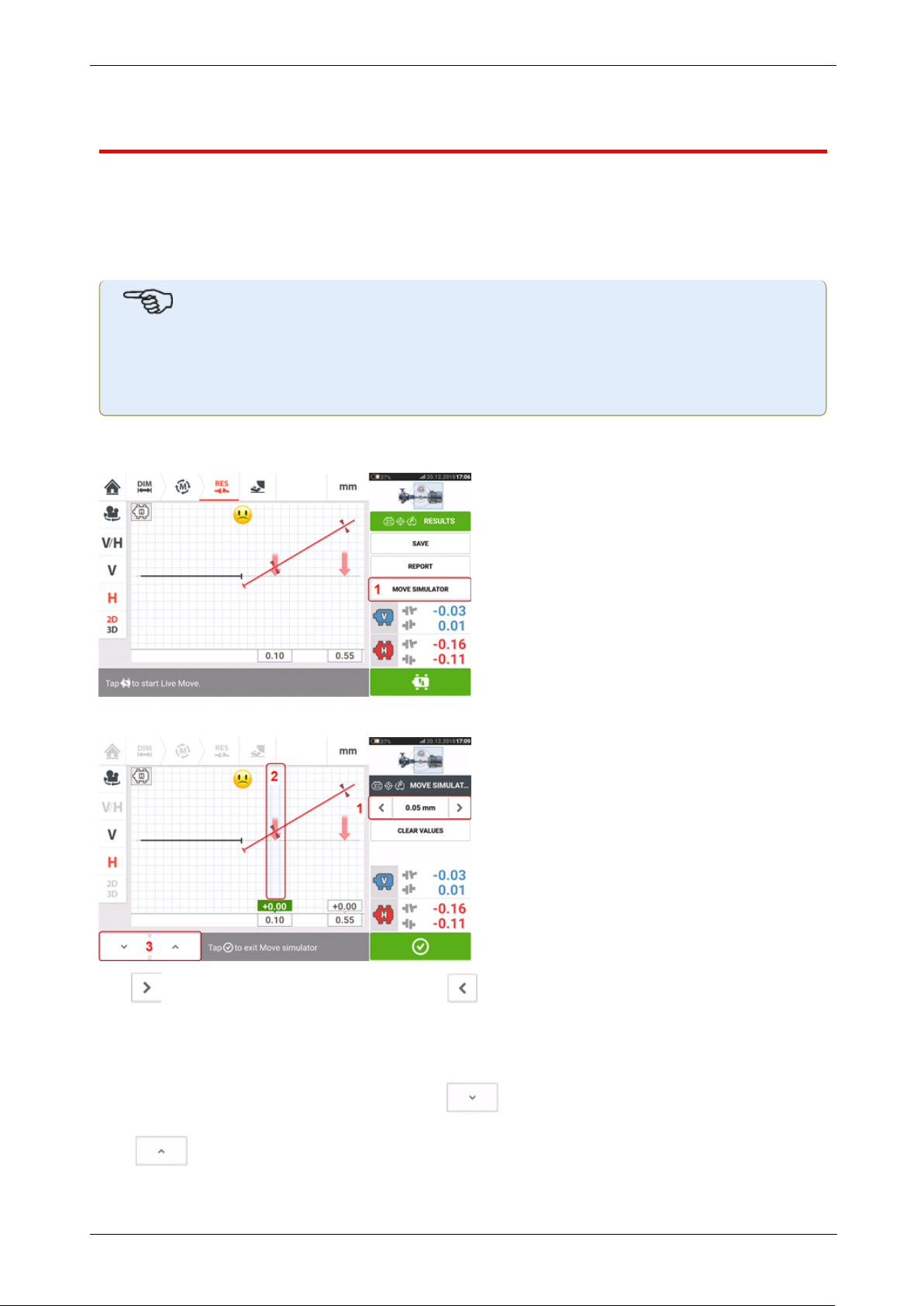
The Move simulator is initiated from the results screen. After taking a measurement, display
the results in either 2D or 3D and on a single plane only.
Tap 'Move simulator' (1).
Tap to increase movement step value or to decrease step value (1). The step value
ranges from 0.025 mm – 1.0 mm for metric units and 1.0 thou – 40.0 thou for imperial units.
Tap machine feet pair to be simulated. A light blue cursor appears on the selected feet pair
(2).
With the cursor on the selected feet pair, tap to move the machine downwards (in
Vertical view) or towards viewer (in Horizontal view) by the movement step value factor. Tap-
ping moves the machine upwards (in Vertical view) or away from viewer (in Horizontal
view) [3] by the movement step value factor. Carry out the simulation while observing the
78 Version:2.3
Page 80
On-board help
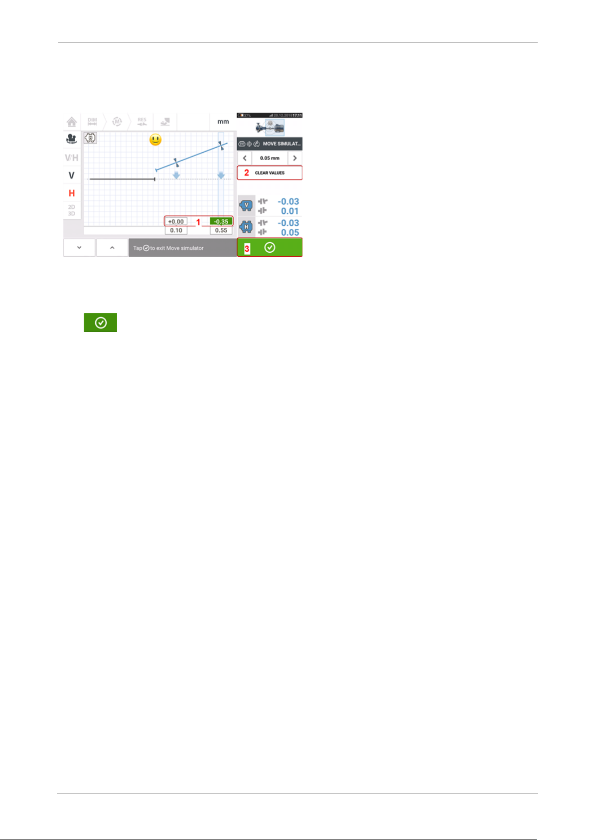
displayed color-coded shaft and coupling, the bold tolerance arrows and the smiley. Aim for a
happy smiley (indicated by blue shaft and tolerance arrows) or an 'OK' smiley (indicated by
green shaft and tolerance arrows).
The amount and direction in which the machine should be moved are displayed on the value
boxes (1) above the measured feet values.
To remove the simulation values, tap 'Clear values' (2).
Tap (3) to exit the Move simulator.
ROTALIGNtouch EX 79
Page 81
On-board help
Saving asset measurements
Saving an asset
Before switching off the instrument, dimensions, measurements, results and all settings can
be saved for analysis, future use or record purposes in the instrument’s memory or transferred via Cloud or USB to ARC 4.0 the PC software. Asset measurements are saved from the
results screen.
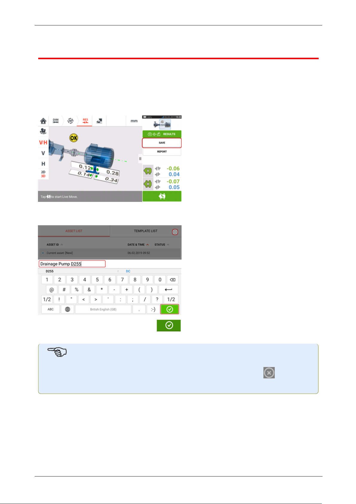
To save an asset measurement, tap the menu item "Save" then use the onscreen keyboard to
enter the measurement file name.
Once asset name has been entered, tap to save the asset under "Asset park". This is
the location where asset measurements are saved.
Note
If for any given reason, the asset is not to be saved, tap the cancel icon [ ] to cancel
saving.
Asset refers to machinery and equipment within a plant. The asset is listed as an Asset ID.
Access "Asset park" via the home screen.
80 Version:2.3
Page 82
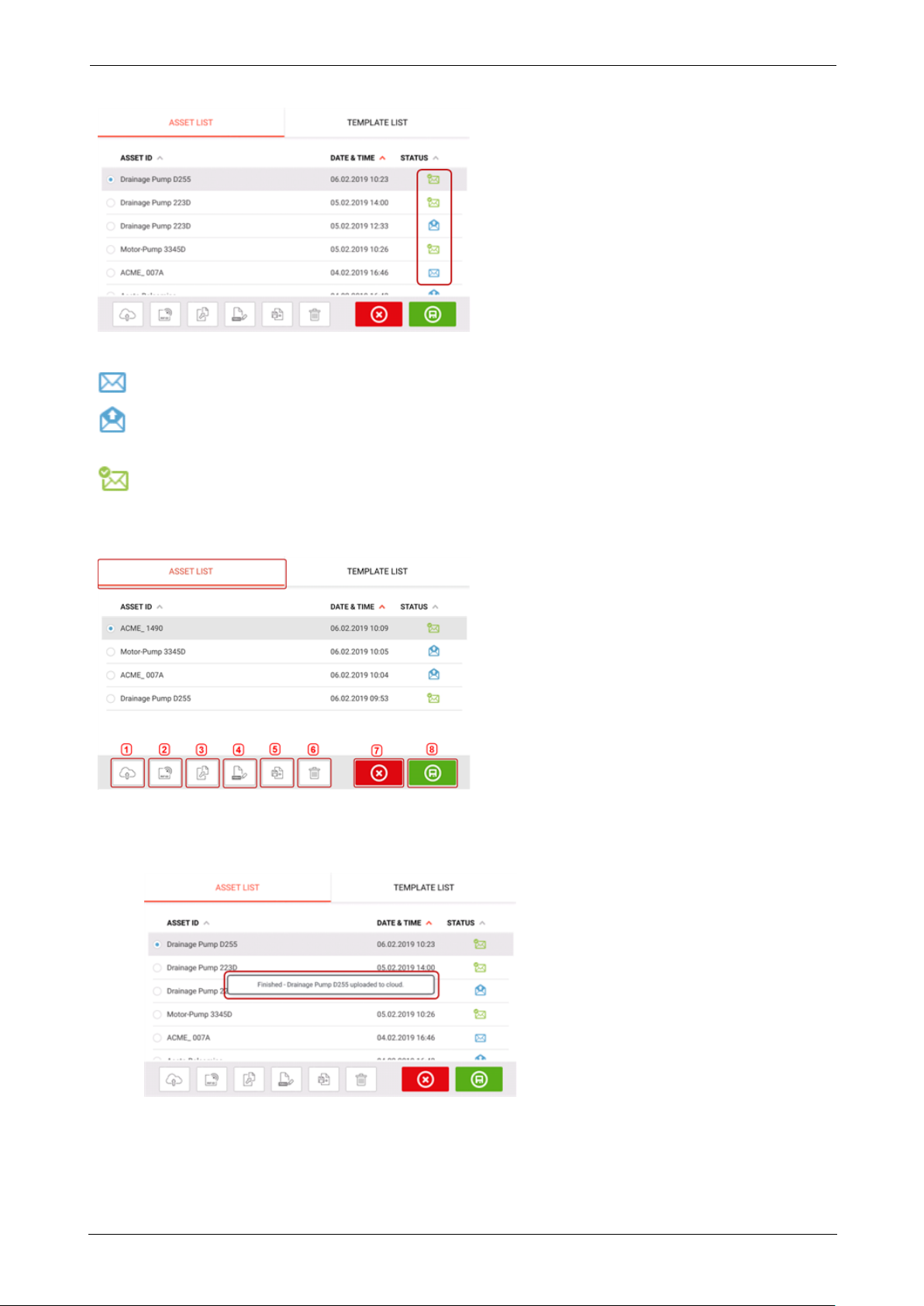
The status envelopes indicate whether an asset has been measured or not.
On-board help
l
l
This icon shows that the asset has been imported from ARC 4.0 but is yet to be opened.
This icon shows that the asset has been opened but the alignment measurement has not
been completed.
l
This icon shows that the alignment measurement has been completed.
Asset list options
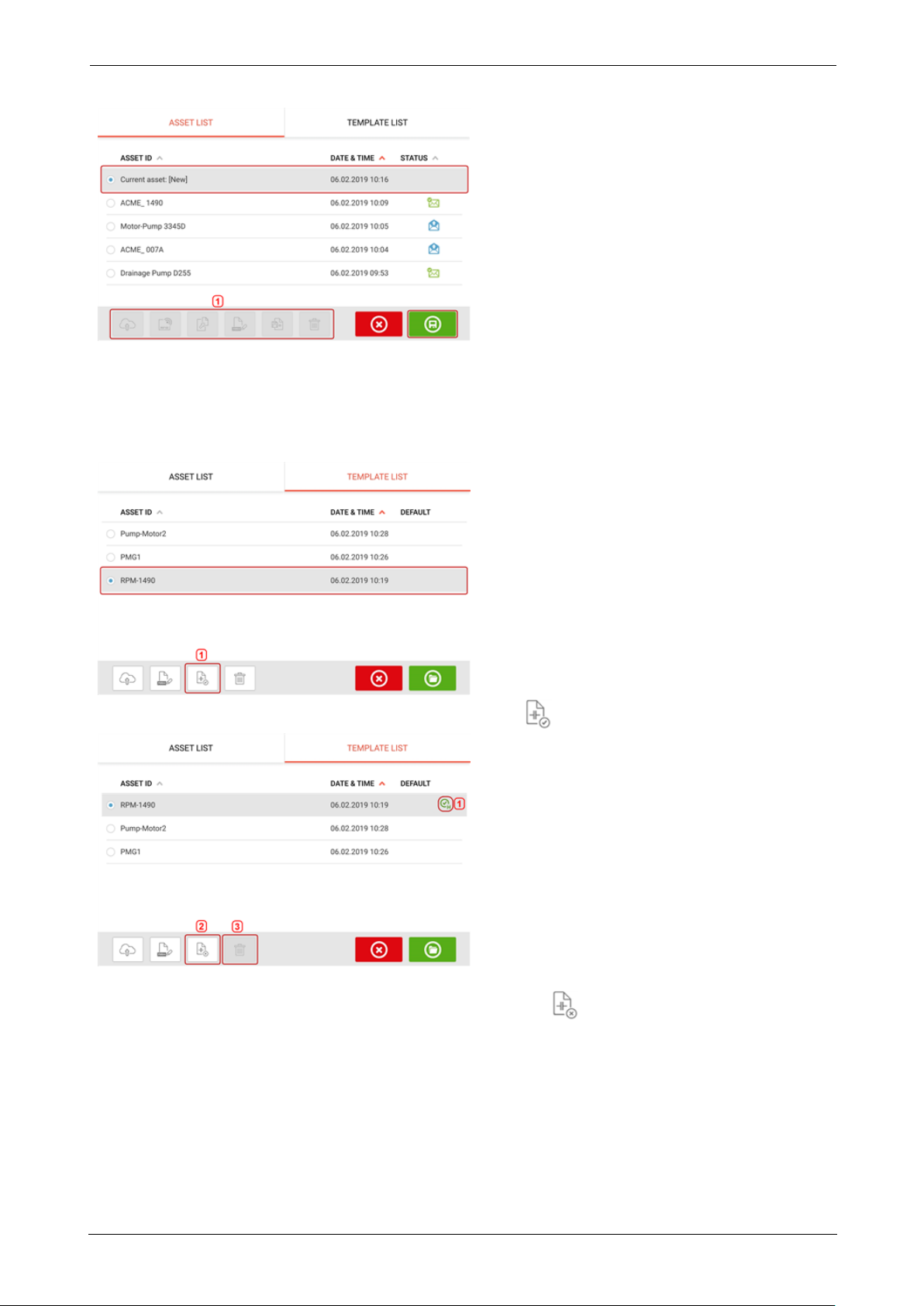
By tapping the respective icon, the following actions may be taken on any selected asset.
l (1) Uploads the selected asset to the cloud. Note: The action is completed only if wire-
less connection is enabled.
ROTALIGNtouch EX 81
Page 83
On-board help
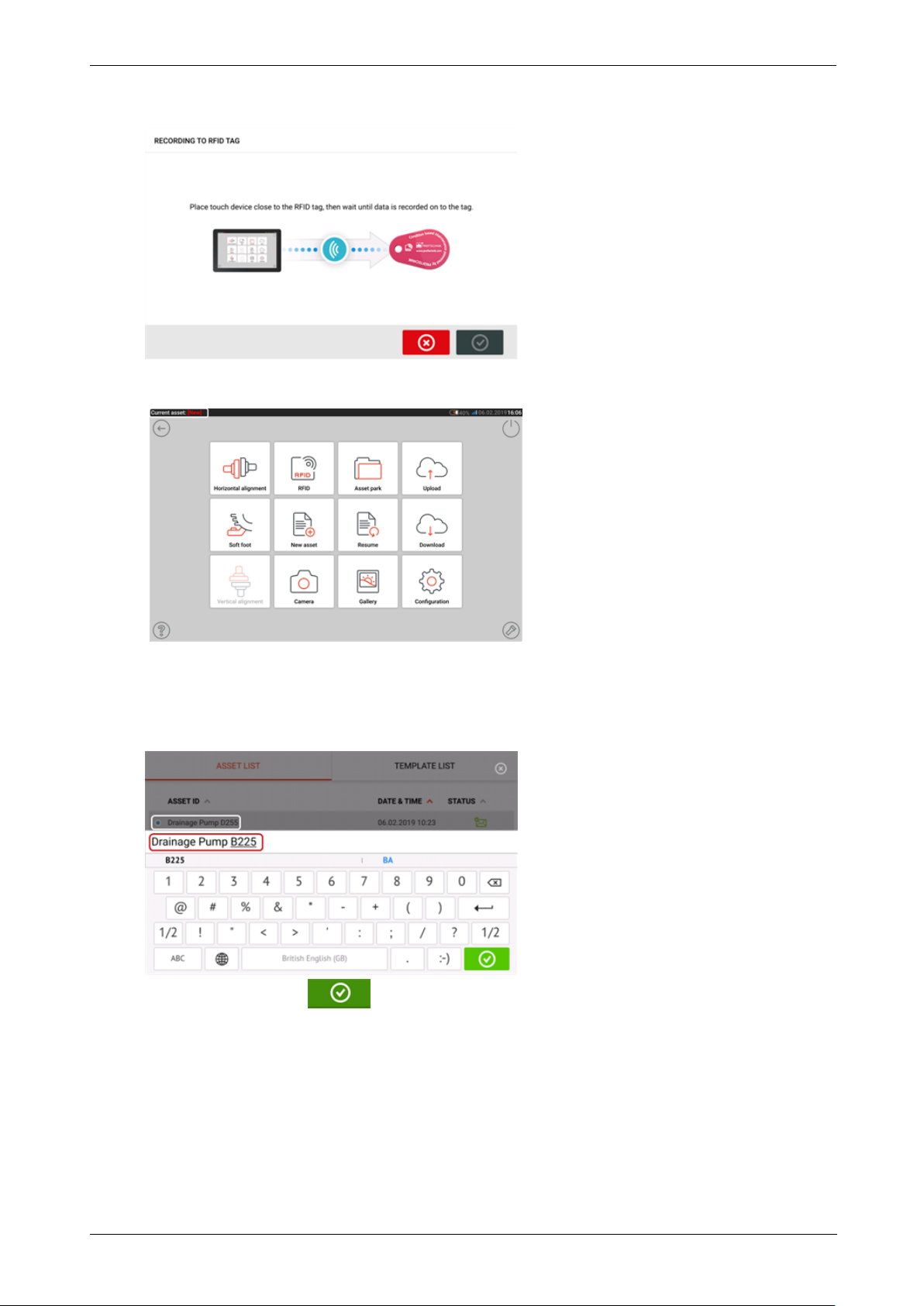
l (2) Assigns selected asset to an RFID tag.
l (3) Opens the selected asset a new asset. The new asset will be a copy of the selected
asset without the sensor-to-coupling center dimension and any asset measurements.
Start desired application by tapping the appropriate icon on the home screen. The new
asset opens and may be edited as required.
Assets opened in this manner are used as templates.
This asset is then saved with a new asset name.
l (4) Used to edit directly the name of the selected asset.
Once completed, tap . The asset will now appear in the asset list with the new
name.
l (5) Used to create a template.
A template is a file that serves as a pattern for alignment set-ups that are repeated frequently. Their main purpose is to save time by not having to reconfigure the same setup many times. It can contain all known dimensions (except sensor-to-coupling center),
target specifications, thermal growth values, tolerances, preferred measure mode, preferred machine icons and coupling types.
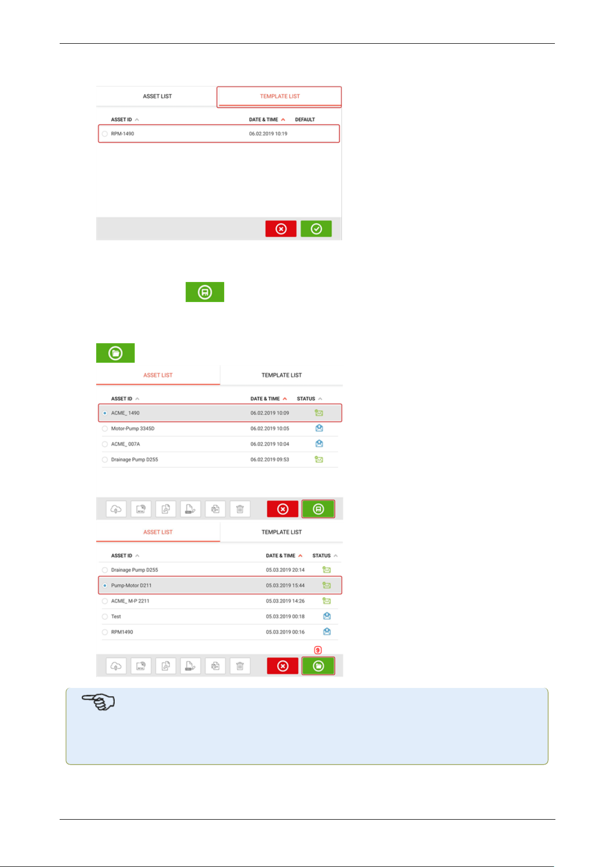
> After an asset has been created and saved, it appears on the asset list.
82 Version:2.3
Page 84
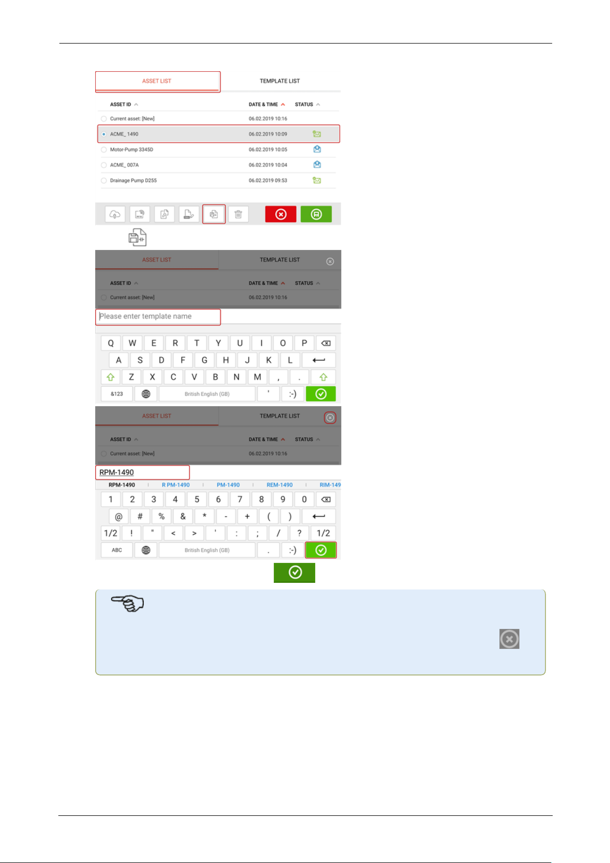
> Tap to save the asset as a template.
On-board help
> Enter name of template then tap .
l
Note
If for any given reason, the template is not to be saved, tap the cancel icon [ ]
to cancel saving.
ROTALIGNtouch EX 83
Page 85
On-board help
> The created template now appears on the template list.
l (6) Used to delete selected asset.
l (7) Used to exit the asset list/template list screen and return to the home screen.
l
(8) This symbol ( ) signifies that the selected asset is open and running in the
background. The symbol serves the dual purpose of either opening the selected asset or
saving any changes that may have been applied to the asset but not yet saved. If an
asset that was previously saved but currently not open is selected, then the symbol
(9) appears.
Note
If the selected asset has not been previously saved then all the asset list options (1) are
inactive.
84 Version:2.3
Page 86
On-board help
Default template
It may be necessary to define any one template as the default template. The default template
will be used whenever a new asset is opened within the home screen.
> All available templates are listed on the template list.
> Select template to be designated as default, then tap (1).
> The default template now appears on the template list with a check mark (1).
> To revert the default template to a normal template, tap (2).
> Note: The designated default template cannot be deleted (3). To delete it, it must first be
reverted to a normal template.
ROTALIGNtouch EX 85
Page 87
On-board help
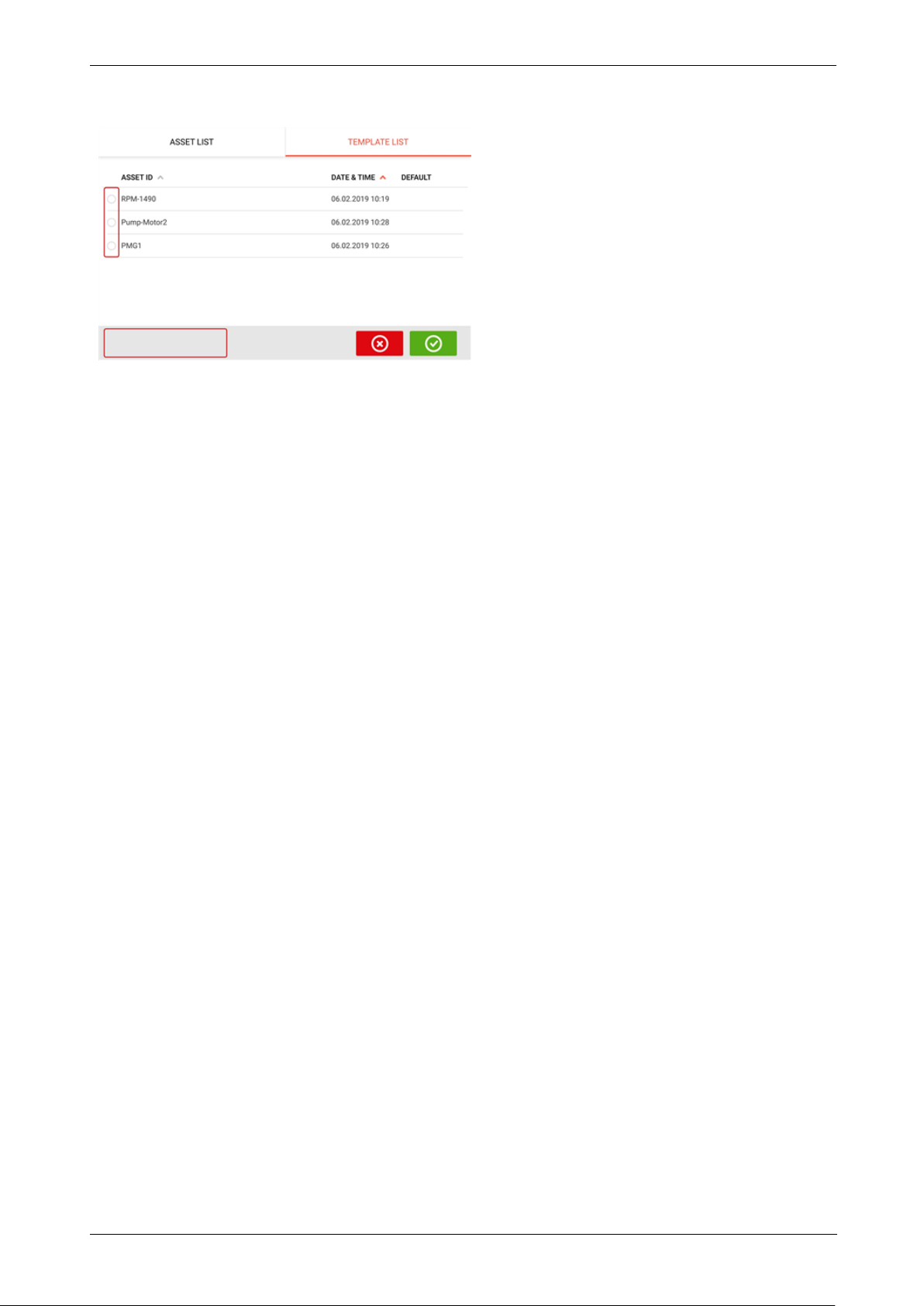
Note: If no template is selected, all template list options are unavailable.
86 Version:2.3
Page 88
On-board help
Generating reports
Generating measurement reports
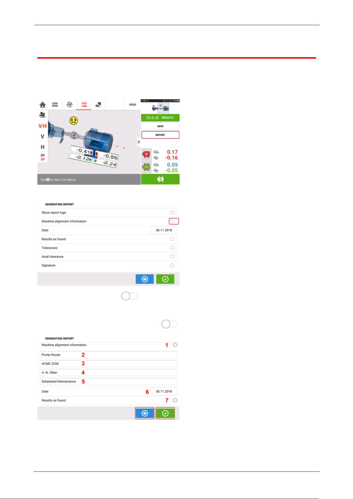
Asset measurement reports may be saved directly on the touch tablet device as a PDF. Measurement reports are generated from the results screen.
Tap the menu item "Report". The "Generating report" screen opens.
If not yet done, tap the icon to activate "Machine alignment information". Once activated, enter the necessary information using the onscreen keyboard. If desired, the items
"Show report logo", "Results as found", "Tolerances", "Axial clearance" and "Signature" is
activated by tapping their respective icon .
l (1) "Machine alignment information" activated
l (2) Location where asset is positioned
l (3) Asset (Machine)ID
ROTALIGNtouch EX 87
Page 89
On-board help
l (4) Name of operator
l (5) Any other machine relevant notes
l (6) Date is set automatically
l (7) In this case, "Results as found" has been activated
Tap to save the asset measurement report as PDF to the ruggedized tablet.
Note
The report as a PDF may be accessed by connecting the tablet device to a PC. The report
is located in the folder "Reports" which is accessed via 'ROTALIGNtouch
EX'/'Media'/'Reports'.
The generated PDF report saved together with the asset may also be accessed via the
software platform ARC 4.0 in "Asset Attachments".
Tapping saves the machine alignment information, then returns the user to the Results
screen.
Report logo
The desired report logo must initially be saved within the touch device before it can be added
to the measurement report.
Note: Adding a new logo to the report logo gallery is only possible if the item "Show report
logo" is activated.
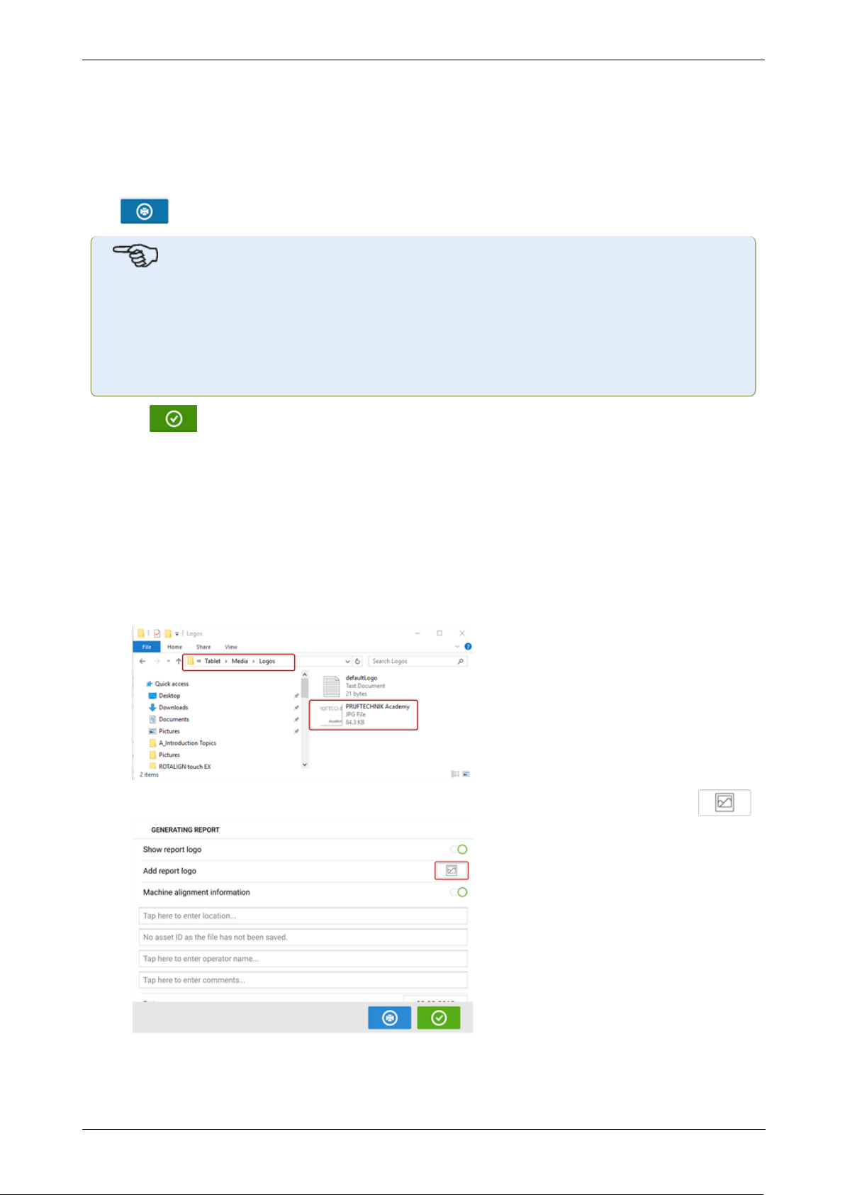
l With the tablet device connected to a PC and access allowed, save the desired logo in
the folder "Logos" which is accessed via 'ROTALIGNtouch EX'/'Media'/'Logos'.
l
Disconnect the tablet device from the PC and then tap the "Add report logo" icon .
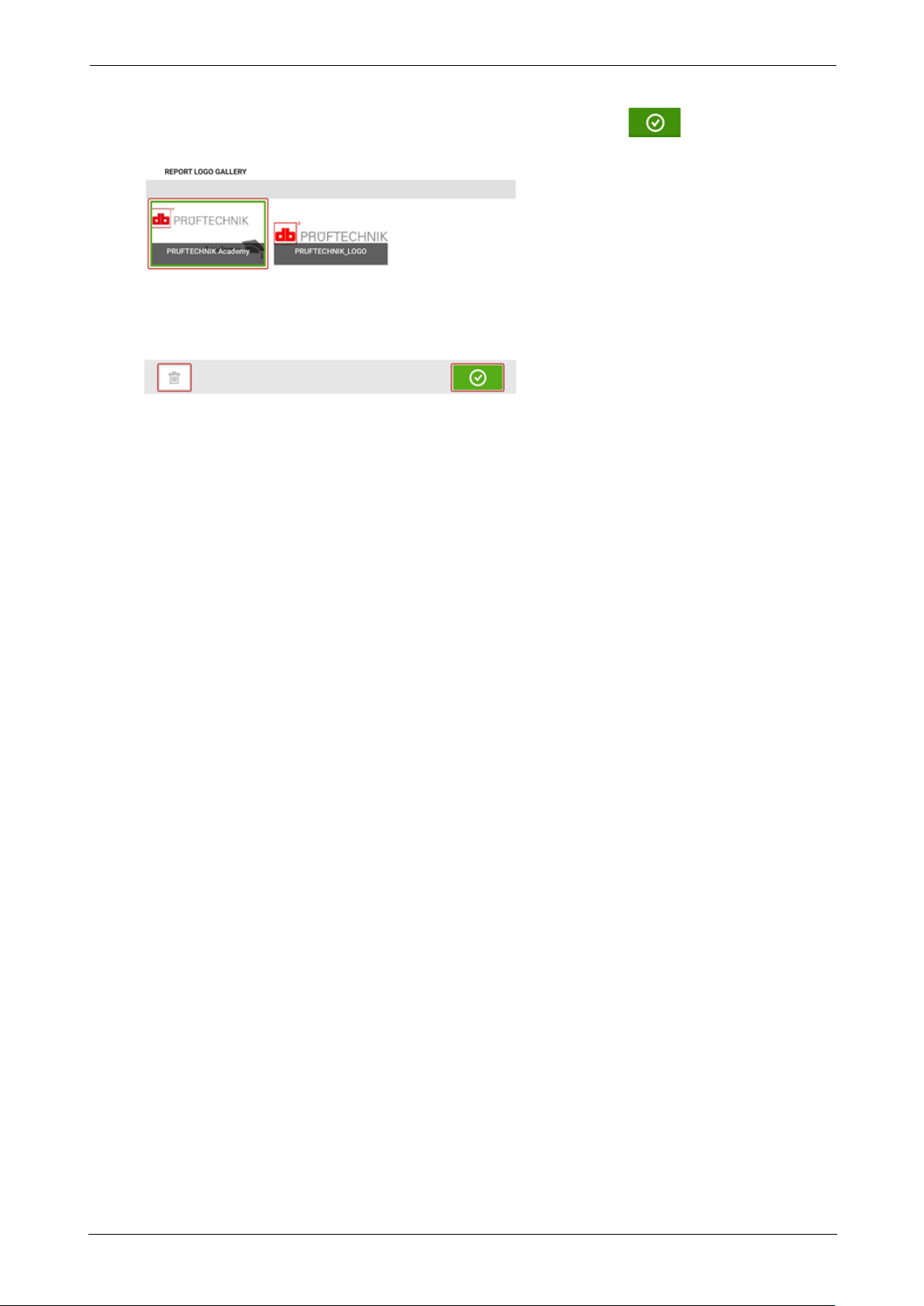
The report logo gallery opens.
88 Version:2.3
Page 90
On-board help
l
From the report logo gallery, tap the desired logo and then tap . The selected logo
will now appear on the PDF measurement report when "Show report logo" is activated.
Note: The delete icon is active. In this case, the added logo can be deleted from the gallery.
ROTALIGNtouch EX 89
Page 91
On-board help
Measurement table
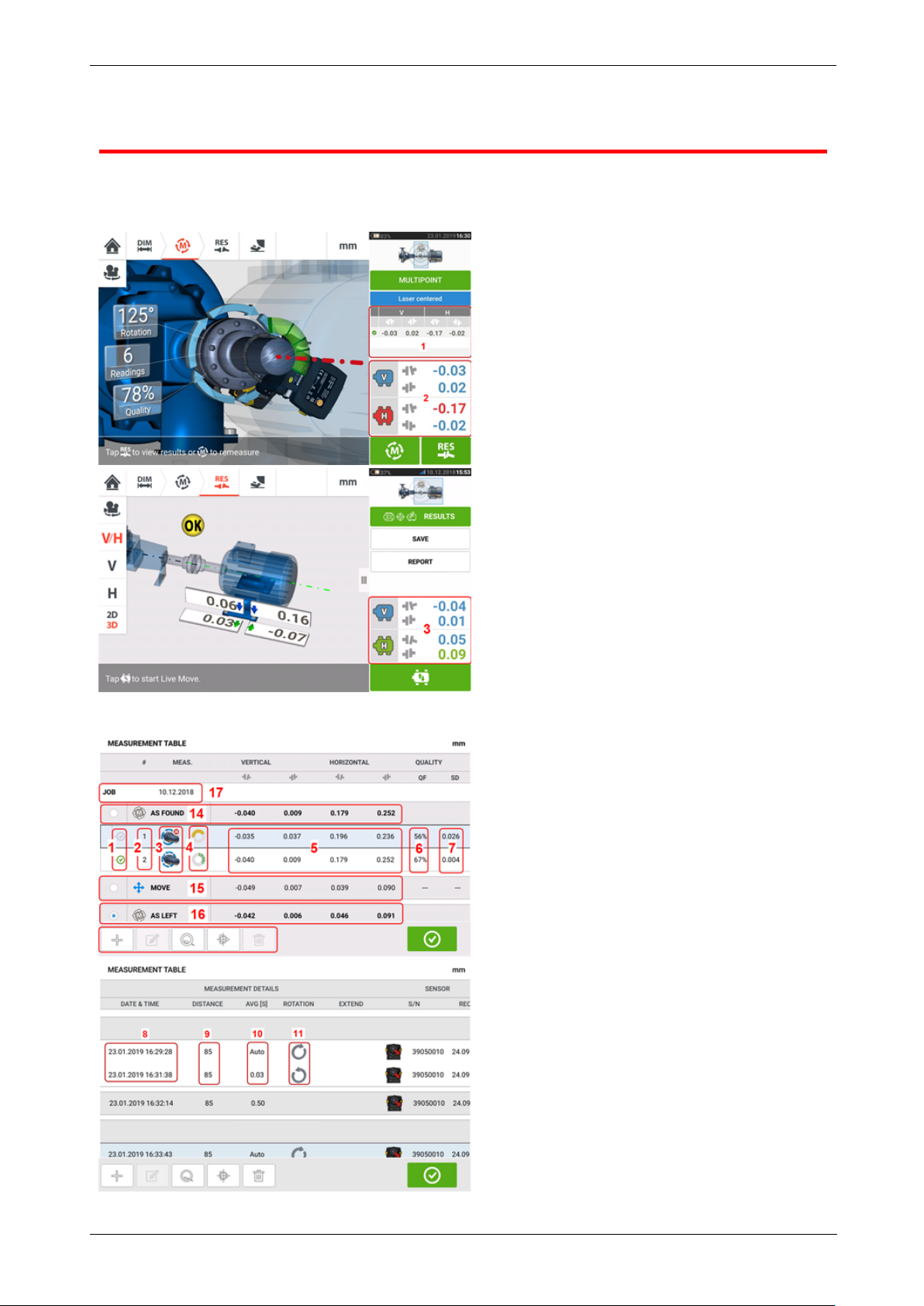
The measurement table is used to register and display all Shaft alignment, and any Live Move
measurements taken on the current couplings. Access the measurement table by tapping
either the results repeatability table (1) or coupling results (2) / (3).
The following items are included in the measurement table for each measurement.
90 Version:2.3
Page 92
On-board help
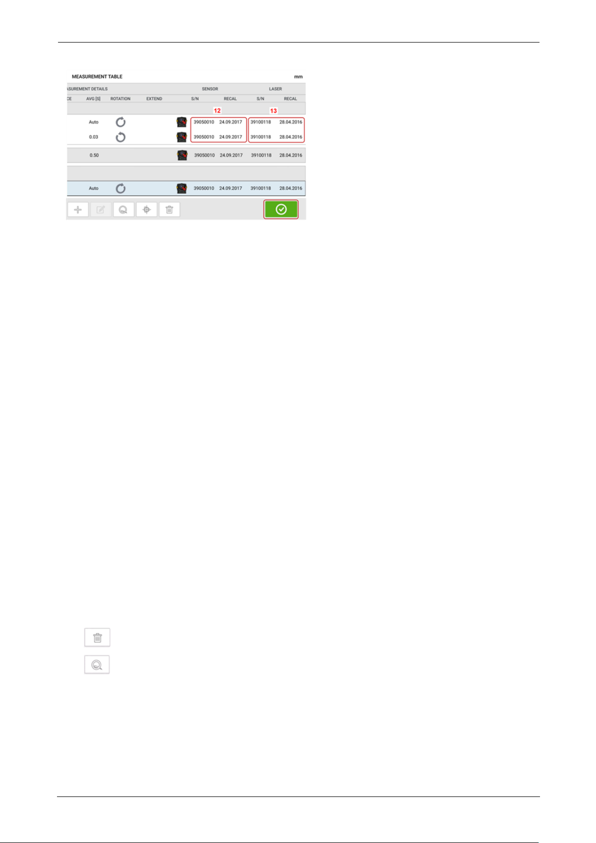
l (1) Tap the check box to include the measurement in calculating the averaged results
that is displayed on the results screen. Included measurements have a green check
mark. The check mark remains grayed out if the measurement is not selected.
l (2) Measurements in chronological order
l (3) Used measurement mode
l (4) The rotational angle covered during measurement
l (5) Vertical and horizontal gap and offset values
l (6) Measurement quality factor (QF)
l (7) Measurement standard deviation (SD)
l (8) Date and time when measurement was taken
l (9) Dimension sensor-to-coupling centre
l (10) Averaging used
l (11) Direction of shaft rotation during measurement
l (12) Serial number of sensor used and recalibration due date
l (13) Serial number of laser used and recalibration due date
The "ASFOUND" coupling result (14) shows the initial alignment condition of the machines
before any Live Move is performed. The displayed result could be an average of selected measurements. In the following table, the "ASFOUND" coupling result is the selected measurement
number 2 only.
The "MOVE" result (15) shows the alignment condition after Live Move.
The "ASLEFT" coupling result (16) shows the alignment condition measured after Live Move.
The displayed result could be an average of selected measurements. In the following table,
the "ASLEFT" coupling result is the average of measurements numbers 1 and 2.
The "JOB" date (17) appears whenever a new alignment job is started.
Swipe horizontally to view all columns in the table and vertically to view all rows in the table.
Tap to delete highlighted "AS LEFT" reading from the measurement table.
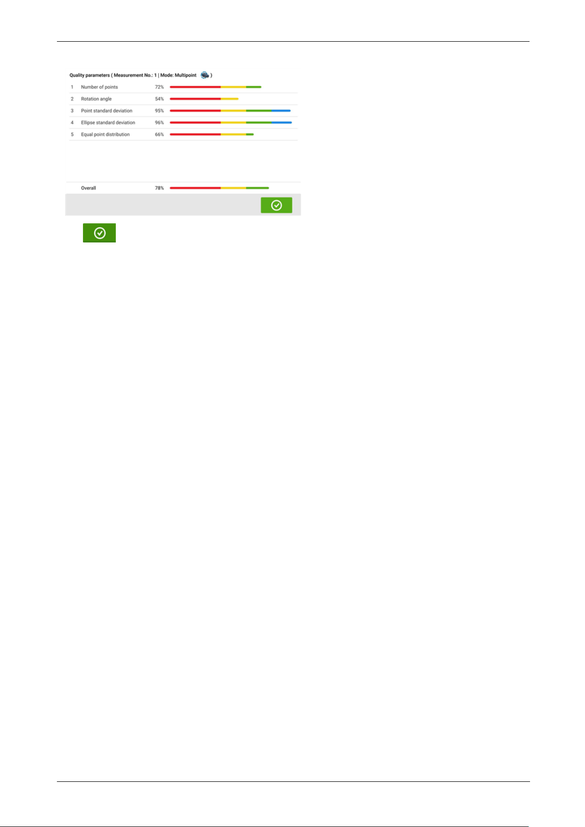
Tap to display the parameters determining the quality factor of the measurement.
ROTALIGNtouch EX 91
Page 93
On-board help
Tap to exit the measurement table.
Measurement quality
Measurement quality is depicted using the following colour codes:
Blue – excellent; Green – acceptable; Yellow – not acceptable; Red – poor
Measurement quality is based on the following measurement and environmental criteria:
l Rotation angle – the angle through which the sensor and/or shaft is rotated during meas-
urement
l Ellipse standard deviation – the root mean square deviation of the measurement points
on the calculated ellipse
l Environmental vibration – the level of external vibration e.g. from neighbouring running
machine(s)
l Rotation evenness – the smoothness of the measurement rotation e.g. if there is any fric-
tion during the rotation that ‘jerks’ the shaft
l Angle rotation inertia – abrupt changes in the measurement rotation speed e.g. releas-
ing and re-applying a break during the rotation
l Rotation direction – change in the measurement rotational direction
l Rotational speed – how fast the sensor and/or shaft is rotated during measurement
l Filter output – the amount of measurement data filtered out
92 Version:2.3
Page 94
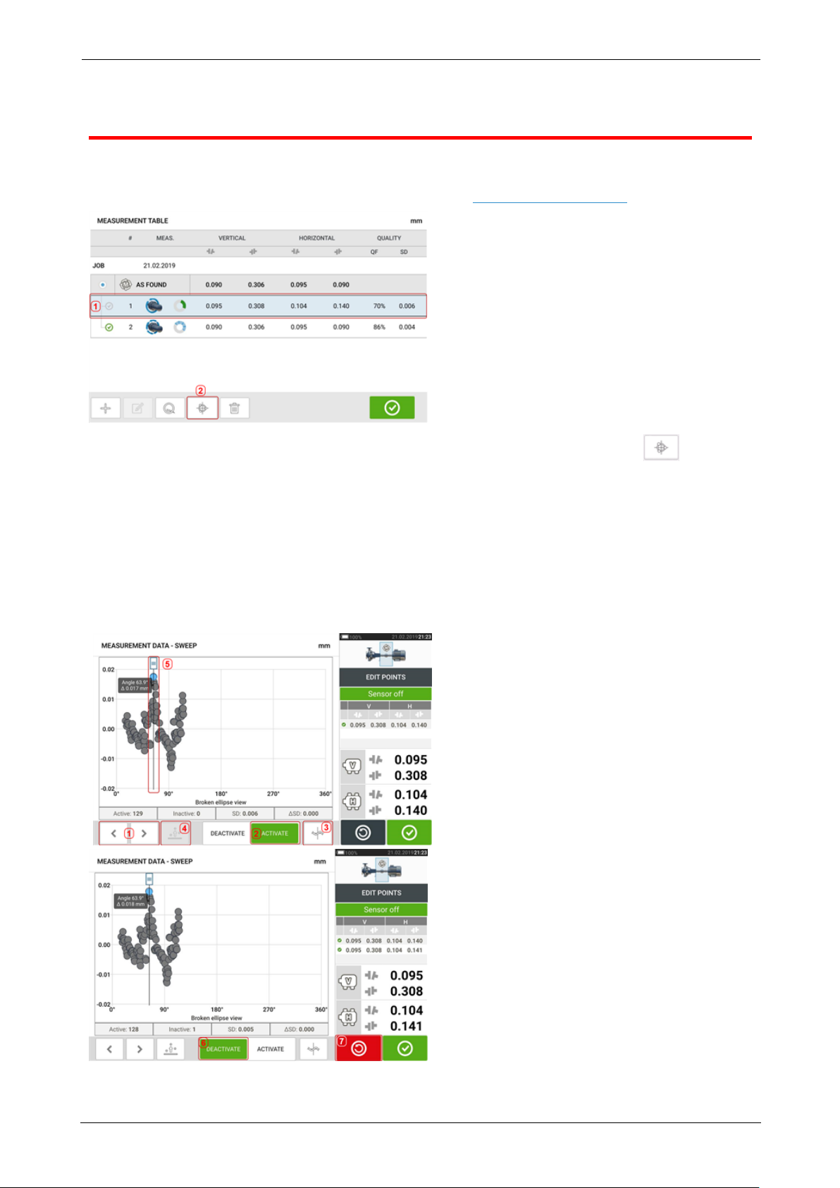
On-board help
Editing measurement data
To improve the quality of the alignment results, it is possible to edit measurement data that
could have been affected by external circumstances such as bracketing touching piping
arrangement. The editing options are accessed via the measurement table.
When in the measurement table screen, tap desired measurement (1) then tap (2) to
access the measurement data screen.
Broken ellipse
The most commonly used deviation diagram is referred to as 'broken ellipse'. During measurement, the laser beam traverses an arc that is dependent on the alignment condition of the
rotating shafts. Over a complete 360° rotation, the beam describes an ellipse. Cutting the
ellipse and laying it out flat results in the deviation diagram 'broken ellipse'. In this diagram
points out of track are clearly seen.
ROTALIGNtouch EX 93
Page 95
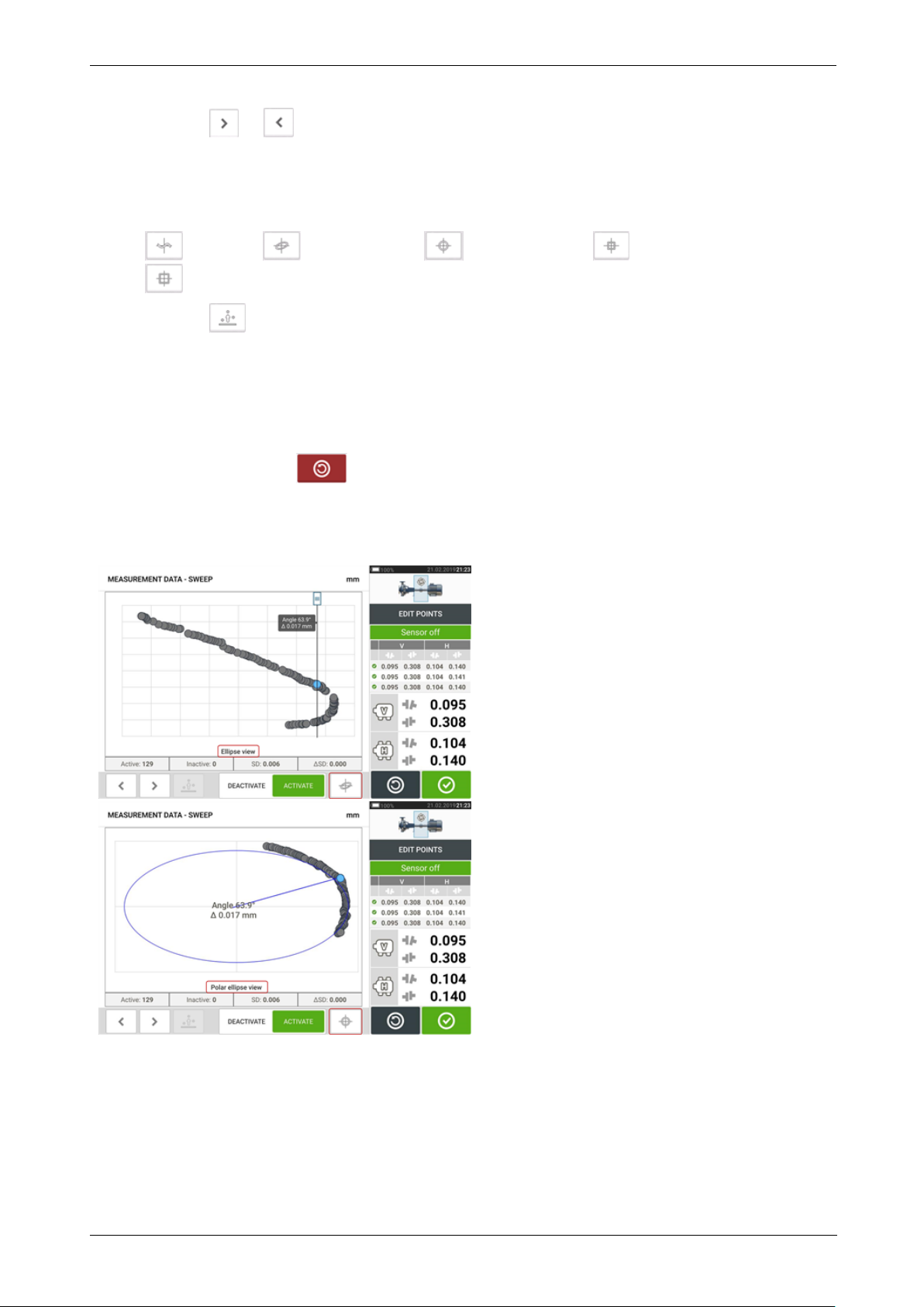
On-board help
l
(1) Tap or to cycle through the points.
l (2) Currently selected point is active. The point is made inactive by tapping 'Deactiv-
ate'.
l (3) Shows currently displayed deviation diagram or sensor plane. Tap icon to cycle
through available deviation diagrams and sensor planes. These include: Broken ellipse [
]; Ellipse [ ]; Polar ellipse [ ]; Sensor plane [ ]; Sensor plane zoomed [
]
l
(4) Tap to automatically select the point with the highest deviation within the dia-
gram. The cursor (5) springs automatically to this point. Note that the icon is inactive
when the currently highlighted point has the highest deviation within the group.
l (5) The cursor is used to highlight any point in the diagram. The selected point is high-
lighted blue.
l (6) Currently selected point is inactive. The point is made active by tapping 'Activate'.
l
(7) The 'undo' icon is used to reverse all changes made before saving the asset
measurement.
Other deviation diagrams
94 Version:2.3
Page 96
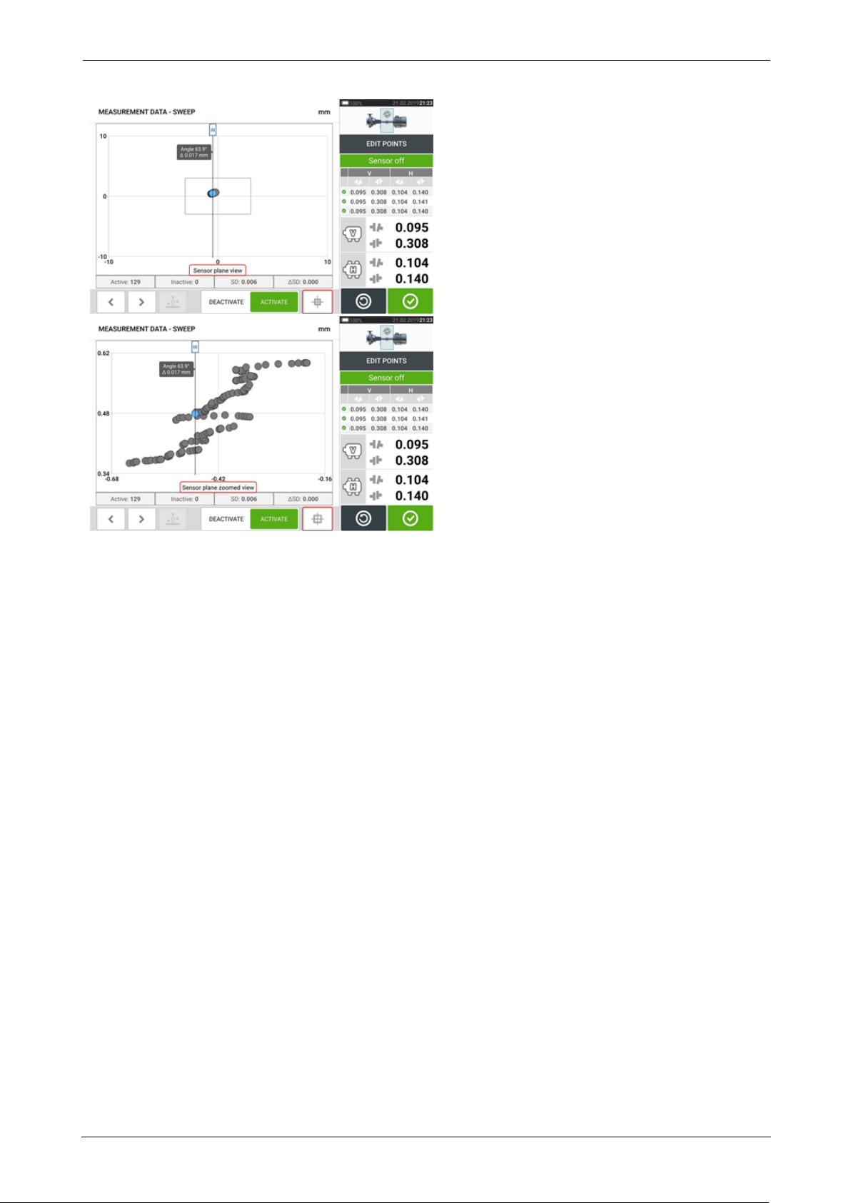
On-board help
All deviation diagrams show the actual number of active and inactive points, the current standard deviation (SD), and the total change in standard deviation (delta SD) when deviant points
are deactivated.
What is the effect of deactivating individual points?
Individual points are deactivated in order to lower the standard deviation value. Change in
standard deviation impacts the V and H results displayed in the results repeatabilty table. Results with a green check mark indicate results with better standard deviation.
ROTALIGNtouch EX 95
Page 97
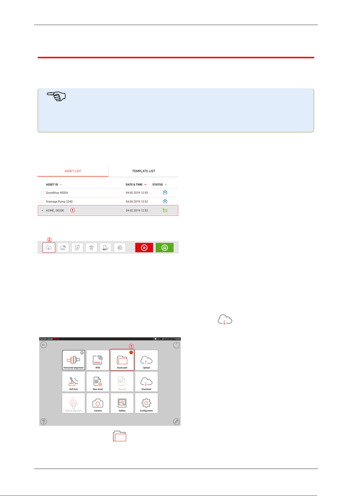
On-board help
Using Cloud drive
To set up the PRÜFTECHNIKCloud drive, an ALIGNMENTRELIABILITYCENTER4.0 (ARC4.0)
licence is required. The Cloud drive allows the sharing of up-to-date asset measurements from
different devices via the PC software ARC 4.0.
Note
Wireless connection between the ruggedized tablet and a network must be established
to enable assets to be transferred via ARC4.0.
Transferring an asset to the Cloud drive
After finalizing a measurement save the asset (1) then upload it to Cloud drive.
Tap the "Upload" icon (2) The asset appears in ARC 4.0 "Exchange" view with the status "complete". Drag and drop the asset in its appropriate location on the Cloud drive.
Downloading an asset from Cloud drive
From the ARC 4.0 "Exchange" view, drag and drop the desired asset into the Name pane. The
asset appears with the status "ready".
From the touch device home screen, tap the "Download" icon . The selected asset
appears in the asset park (1).
Tap the "Asset park" icon to open the asset in the ruggedized tablet .
96 Version:2.3
Page 98
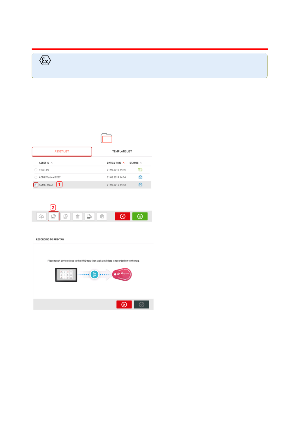
On-board help
RFID
Only intrinsically safe RFID tags must be used in explosive atmospheres.
The ruggedized tablet uses this automatic identification technology to perform the following:
l Identify assets to be aligned
l Enter corresponding assets directly into the device
l Store data and results under the correct asset automatically
Assigning a saved asset to an RFIDtag
From the home screen, tap the "Asset park" icon to display assets saved.
Tap the asset [1] that is to be assigned to the RFIDtag, then tap the RFID icon [2].
Position the touch device such that its built-in NFC antenna is as close to the RFID tag as possible (less than a centimeter).
ROTALIGNtouch EX 97
Page 99
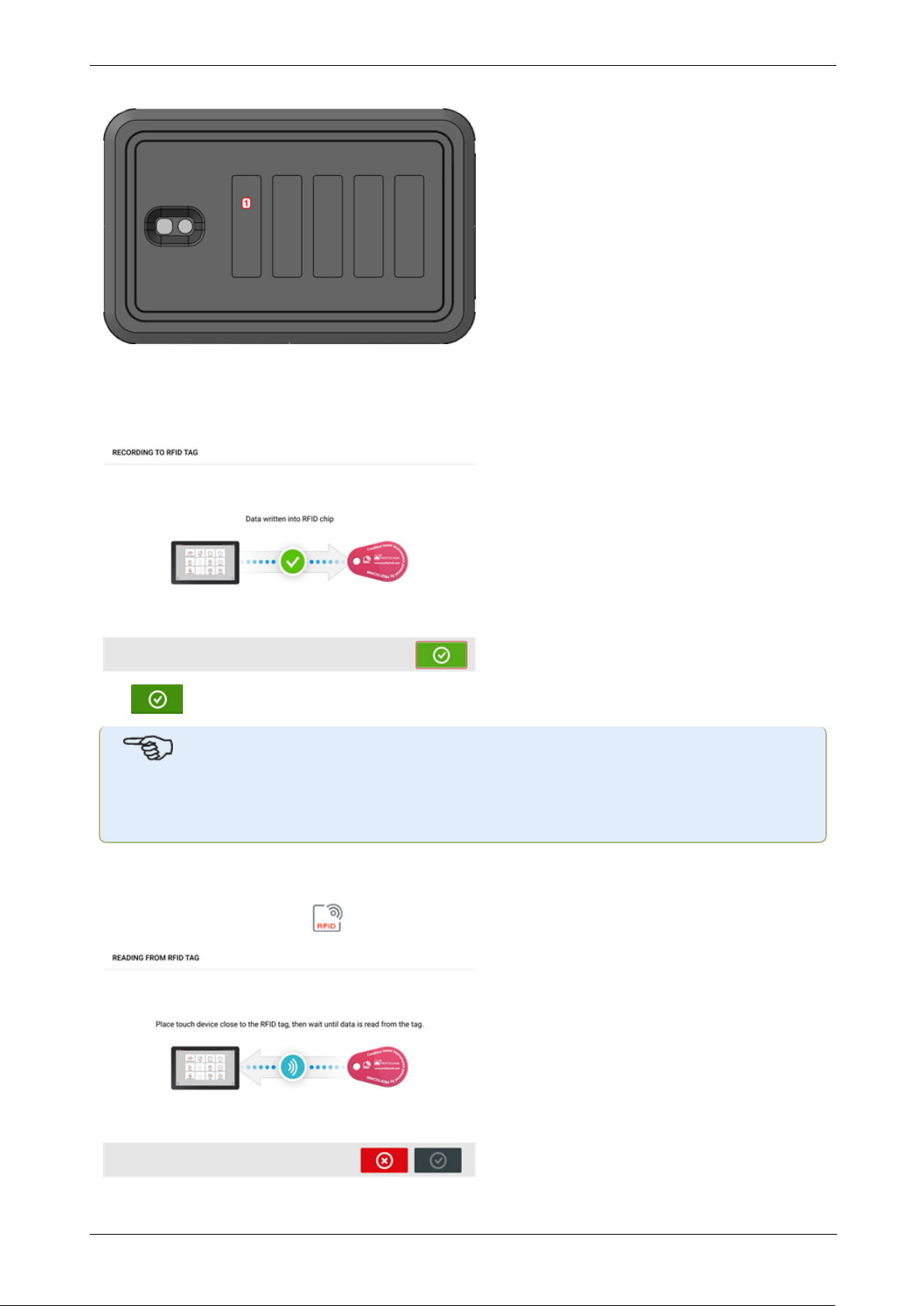
On-board help
l (1) Near Field Communication (NFC) antenna symbol
As soon as data has been written on the RFIDtag, the corresponding hint appears on the display.
Tap to exit the screen.
Note
If however, data had already been assigned to the RFIDtag, a hint requesting overwriting of the data appears.
Opening an asset measurement assigned to an RFIDtag
From the home screen, tap the "RFID" icon.
98 Version:2.3
Page 100
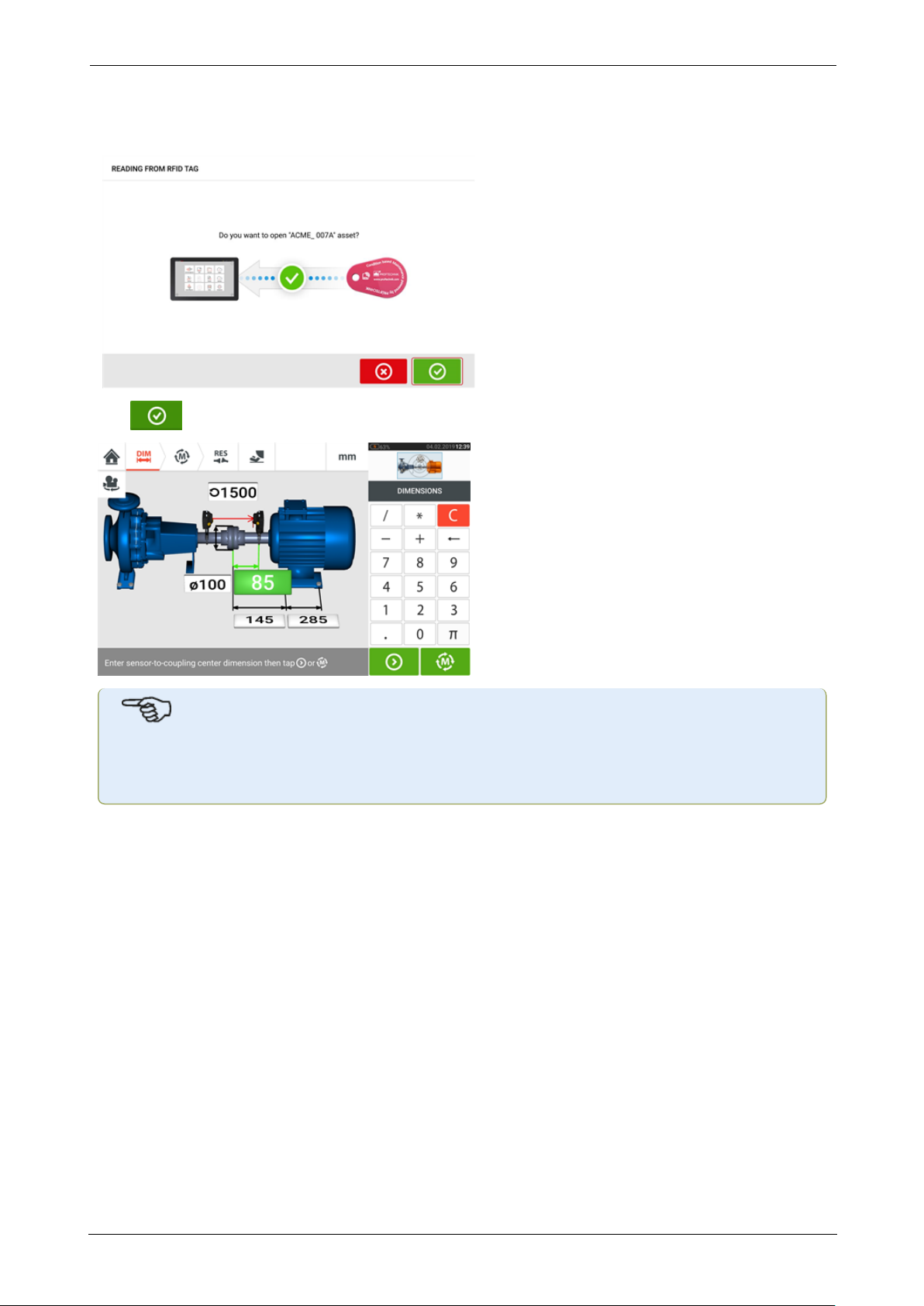
On-board help
Position the touch device such that its built-in NFC antenna is as close to the RFID tag as possible (less than a centimeter).
Tap to open the asset measurement.
Note
If however, no data had been written on the RFIDtag, a hint on missing information
appears.
ROTALIGNtouch EX 99
 Loading...