

Page 1

PG7601-SYS-AF™
Gas Operated Piston Gauge
Pressure Calibration System
Operation and Maintenance Manual
NSN 6695-01-551-5125
Consists of Base System and Exchange Pack
© 2007 DH Instruments, a Fluke Company
Page 2

PG7601-SYS-AF™ OPERATION AND MAINTENANCE MANUAL
High-pressure liquids and gases are potentially hazardous. Energy stored in these liquids and gases
can be released unexpectedly and with extreme force. High-pressure systems should be assembled and
operated only by personnel who have been instructed in proper safety practices.
© 2007 DH Instruments, a Fluke Company All rights reserved.
Information in this document is subject to change without notice. No part of this document may be reproduced or transmitted in any
form or by any means, electronic or mechanical, for any purpose, without the express written permission of DH Instruments, a
Fluke Company. 4765 East Beautiful Lane Phoenix Arizona 85044-5318 USA.
DH Instruments makes sincere efforts to ensure the accuracy and quality of its published materials; however, no warranty,
expressed or implied, is provided. DH Instruments disclaims any responsibility or liability for any direct or indirect damages
resulting from the use of the information in this manual or products described in it. Mention of any product or brand does not
constitute an endorsement by DH Instruments of that product or brand. This manual was originally composed in English and was
subsequently translated into other languages. The fidelity of the translation cannot be guaranteed. In case of conflict between the
English version and other language versions, the English version predominates.
DH Instruments, DH, DHI, PG7601-AF, PG7601, PPPC3, CalTool and COMPASS are trademarks, registered and otherwise, of
DH Instruments, a Fluke Company.
Swagelok is a registered trademark of the Swagelok Company.
Krytox is a registered trademark of the Dupont de Nemours Company.
Products described in this manual are manufactured under international patents and one or more of the following U.S.
patents: 6,701,791, 5,142,483, 5,257,640, 5,331,838, 5,445,035. Other U.S. and international patents pending.
Document No. 550152a-01
071001
Printed in the USA
© 2007 DH Instruments, a Fluke Company
Page 3

TABLE OF CONTENTS
T
AABBLLEE OOFF
T
C
OONNTTEENNTTS
C
S
TABLE OF CONTENTS ...............................................................I
TABLES................................................................................VII
FIGURES................................................................................IX
ABOUT THIS MANUAL............................................................. XI
1. INTRODUCTION ................................................................. 1
1.1 SPECIFICATIONS....................................................................................................................................1
1.1.1 OVERALL SYSTEM SPECIFICATIONS........................................................................................................1
1.1.1.1 PRESSURE MEASUREMENTS................................................................................................................2
1.1.2 PISTON GAUGE PLATFORM (PG7601-AF).................................................................................................2
1.1.2.1 EMBEDDED FEATURES...........................................................................................................................3
1.1.2.2 MEASUREMENT OF AMBIENT AND INSTRUMENT CONDITIONS........................................................4
1.1.3 PISTON-CYLINDER MODULES (PC-7100/7600-10-L, -50, -200)............................................................5
1.1.4 MASS SET (MS-7001-35-AF)........................................................................................................................6
1.1.5 PRESSURE CONTROLLER (PPC3-7M-AF).................................................................................................7
1.1.6 REFERENCE VACUUM PUMP (D16B).........................................................................................................7
2. SYSTEM AND COMPONENT OVERVIEW AND DESCRIPTION .... 9
2.1 SYSTEM OVERVIEW (PG7601-SYS-AF)................................................................................................9
2.2 PISTON GAUGE PLATFORM AND TERMINAL (PG7601-AF).............................................................12
2.2.1 PLATFORM..................................................................................................................................................13
2.2.2 PG TERMINAL.............................................................................................................................................14
2.3 PISTON-CYLINDER MODULES (PC-7100/7600-10-L, -50, -200)...............................................15
2.4 MASS SET (MS-7001-35-AF).................................................................................................................16
2.5 PRESSURE CONTROLLER (PPC3-7M-AF).........................................................................................16
2.6 REFERENCE VACUUM PUMP (D16B).................................................................................................18
3. INSTALLATION ................................................................ 19
3.1 UNPACKING AND INSPECTION...........................................................................................................19
3.1.1 UNPACKING AND INSPECTION OF PG7601-BAS-AF BASE SYSTEM...................................................19
3.1.1.1 PLATFORM, TERMINAL AND BELL JAR (PG7601-AF)........................................................19
3.1.1.2 PRESSURE CONTROLLER (PPC3-7M-AF)...........................................................................................20
3.1.1.3 REFERENCE VACUUM PUMP (D16B)...................................................................................................20
3.1.1.4 PRESSURE INTERCONNECTIONS KIT (PK-7601-P-AF) ......................................................20
3.1.1.5 VACUUM INTERCONNECTIONS KIT (PK-7601-V-AF)..........................................................................21
3.1.1.6 DOCUMENTATION AND ACCESSORIES..............................................................................................21
3.1.2 UNPACKING AND INSPECTION OF PG7601-EXC-AF EXCHANGE PACKAGE......................................21
3.1.2.1 PISTON-CYLINDER MODULES (PC-7100/7600-10-L, PC-7100/7600-50, PC-7100/7600-200) AND
ACCESSORIES .......................................................................................................................................22
3.1.2.2 MASS SET (MS-7001-35-AF)..................................................................................................................22
3.1.2.3 DOCUMENTATION AND ACCESSORIES..............................................................................................23
3.2 SITE REQUIREMENTS..........................................................................................................................23
3.3 PHYSICAL SETUP.................................................................................................................................25
3.3.1 SETTING UP THE PLATFORM...................................................................................................................25
3.3.2 SETTING UP THE PRESSURE CONTROLLER.........................................................................................26
3.3.3 SYSTEM PRESSURE INTERCONNECTIONS............................................................................................26
3.3.4 SETTING UP THE MASS SET ....................................................................................................................27
3.3.5 INSTALLING A PISTON-CYLINDER MODULE INTO THE PLATFORM....................................................28
Page I © 2007 DH Instruments, a Fluke Company
Page 4

PG7601-SYS-AF™ OPERATION AND MAINTENANCE MANUAL
3.3.6 SETTING UP THE REFERENCE VACUUM PUMP AND VACUUM INTERCONNECTIONS.....................29
3.3.7 CONNECTING TEST GAS SUPPLY...........................................................................................................29
3.3.8 CONNECTING CONTROL VACUUM SUPPLY...........................................................................................30
3.4 POWER UP AND VERIFICATION .........................................................................................................30
3.4.1 POWER UP PLATFORM AND PRESSURE CONTROLLER......................................................................30
3.4.2 CHECK THAT ON-BOARD PISTON-CYLINDER MODULE AND MASS SET DIGITAL IDS ARE
CORRECT....................................................................................................................................................31
3.4.3 SET LOCAL GRAVITY VALUE ...................................................................................................................31
3.4.4 CHECK/SET SECURITY LEVEL.................................................................................................................31
3.4.5 CHECK PROPER OPERATION OF AMBIENT CONDITION MEASUREMENTS ......................................31
3.4.6 TURN ON AUTOGEN AND AUTOROTATE................................................................................................32
3.4.7 APPLY SUPPLY PRESSURE .....................................................................................................................32
3.4.8 APPLY CONTROL VACUUM......................................................................................................................32
3.4.9 APPLY REFERENCE VACUUM..................................................................................................................32
3.4.10 SET A GAUGE MODE PRESSURE, CHECK AUTOGEN AND AUTOROTATE FUNCTIONS..................32
3.4.11 CHECK PISTON BEHAVIOR MEASUREMENTS.......................................................................................34
3.4.12 CHECK REFERENCE VACUUM SYSTEM AND ABSOLUTE MODE OPERATION..................................34
3.5 ADDITIONAL PRECAUTIONS TO TAKE TO MAKE GOOD PRESSURE MEASUREMENTS.............36
4. GENERAL OPERATION ..................................................... 37
4.1 OPERATING PRINCIPLES....................................................................................................................37
4.1.1 FUNDAMENTAL OPERATING PRINCIPLE................................................................................................37
4.1.2 PRESSURE CONTROL, MANUAL AND AUTOMATED.............................................................................38
4.1.3 PRESSURE READY/NOT READY INDICATION........................................................................................39
4.1.3.1 PISTON POSITION READY/NOT READY ..............................................................................................39
4.1.3.2 PISTON ROTATION READY/NOT READY.............................................................................................40
4.1.3.3 VACUUM REFERENCE READY/NOT READY.......................................................................................40
4.1.4 PISTON POSITION......................................................................................................................................41
4.1.5 MASS LOADING PROTOCOL ....................................................................................................................42
4.2 USER INTERFACE................................................................................................................................45
4.2.1 PISTON GAUGE (SYSTEM INTERFACE)..................................................................................................45
4.2.1.1 KEYPAD LAYOUT AND PROTOCOL......................................................................................................45
4.2.1.2 MAIN RUN SCREEN................................................................................................................................46
4.2.1.3 GENERAL FUNCTION/MENU FLOW CHART........................................................................................48
4.2.1.4 SOUNDS..................................................................................................................................................48
4.2.2 PRESSURE CONTROLLER........................................................................................................................49
4.2.2.1 KEYPAD LAYOUT AND PROTOCOL......................................................................................................49
4.2.2.2 DIRECT PRESSURE CONTROL KEYS..................................................................................................50
4.2.2.3 MAIN RUN SCREEN................................................................................................................................51
4.2.2.4 SOUNDS..................................................................................................................................................52
4.3 DIRECT FUNCTION KEYS....................................................................................................................53
4.3.1 DIRECT FUNCTION KEYS SUMMARY......................................................................................................53
4.3.2 [P-C], VIEW AND SELECT PISTON-CYLINDER MODULES.....................................................................53
4.3.3 [UNIT], SELECT PRESSURE UNIT OF MEASURE....................................................................................55
4.3.4 [MODE], SELECT PRESSURE MEASUREMENT MODE...........................................................................56
4.3.5 [SYSTEM], VIEW SYSTEM CONDITIONS MEASUREMENT SCREENS..................................................57
4.3.5.1 FIRST SYSTEM RUN SCREEN ..............................................................................................................57
4.3.5.2 SECOND SYSTEM RUN SCREEN .........................................................................................................58
4.3.6 [AMBIENT], VIEW AMBIENT CONDITIONS MEASUREMENTS SCREEN ...............................................59
4.3.7 [HEAD], SET FLUID HEAD CORRECTION HEIGHT..................................................................................60
4.3.8 [ROTATE], MANAGE MOTORIZED PISTON ROTATION..........................................................................62
4.3.8.1 <2PRE-DECEL>.......................................................................................................................................64
4.3.9 [GEN], MANAGE AUTOMATED PRESSURE GENERATION....................................................................64
4.3.9.1 <2TARGET>.............................................................................................................................................66
4.3.9.2 <3RAISE> ................................................................................................................................................66
4.3.9.3 <4UL>.......................................................................................................................................................66
4.3.9.4 <5TOL>....................................................................................................................................................67
4.3.9.5 <6REFLOAT>...........................................................................................................................................67
4.3.9.6 VIEWING AND SETTING PPC3-7M-AF COM1 PORT SETTINGS.........................................................68
4.3.10 [RES], SET MASS LOADING RESOLUTION .............................................................................................68
4.3.11 [SET P], SET OR MEASURE A PRESSURE..............................................................................................69
4.3.11.1 [SET P] IN PRESSURE TO MASS MODE...............................................................................................71
4.3.11.2 [SET P] IN MASS TO PRESSURE MODE...............................................................................................72
4.3.11.3 COMMANDS FOR ZERO PRESSURE, ENDING A TEST......................................................................73
4.3.12 [P OR M], SET PRESSURE TO MASS OR MASS TO PRESSURE OPERATING MODE.........................73
4.3.13 [ ] AND [ ], [←], MANUAL CONTROL OF MOTORIZED ROTATION...............................................74
© 2007 DH Instruments, a Fluke Company Page II
Page 5

TABLE OF CONTENTS
4.4 [SETUP] MENU, MANAGE PRESSURE EQUATION VARIABLE SOURCES......................................75
4.4.1 <1SELECT>.................................................................................................................................................77
4.4.2 <2VIEW>......................................................................................................................................................77
4.4.3 <3EDIT>.......................................................................................................................................................78
4.5 [SPECIAL] MENU..................................................................................................................................81
4.5.1 <1PC/MS>, MANAGE METROLOGICAL ELEMENT DIGITAL IDS............................................................82
4.5.1.1 CREATE PISTON-CYLINDER MODULE.................................................................................................83
4.5.1.2 EDIT PISTON-CYLINDER MODULE.......................................................................................................86
4.5.1.3 VIEW PISTON-CYLINDER MODULE......................................................................................................86
4.5.1.4 DELETE PISTON-CYLINDER MODULE.................................................................................................87
4.5.1.5 SELECT THE ACTIVE PISTON-CYLINDER MODULE...........................................................................87
4.5.1.6 ADD MASS SET.......................................................................................................................................87
4.5.1.7 EDIT MASS SET......................................................................................................................................91
4.5.1.8 VIEW MASS SET.....................................................................................................................................91
4.5.1.9 DELETE MASS SET................................................................................................................................91
4.5.1.10 SELECT MASS SET................................................................................................................................92
4.5.1.11 ADD MASS LOADING BELL....................................................................................................................92
4.5.1.12 EDIT MASS LOADING BELL...................................................................................................................93
4.5.1.13 VIEW MASS LOADING BELL..................................................................................................................94
4.5.1.14 DELETE MASS LOADING BELL.............................................................................................................94
4.5.1.15 SELECT MASS LOADING BELL.............................................................................................................94
4.5.2 <2PRESU>, CUSTOMIZE UNIT FUNCTION SELECTIONS.......................................................................94
4.5.3 <3HEAD>, CUSTOMIZE FLUID HEAD FUNCTIONS .................................................................................96
4.5.3.1 <3HEAD>, <1FLUID>...............................................................................................................................97
4.5.3.2 <3HEAD>, <2UNIT>.................................................................................................................................97
4.5.3.3 <3HEAD>, <3ATM> .................................................................................................................................97
4.5.3.4 <3HEAD>, <4PISTON>............................................................................................................................98
4.5.4 <4PREFS>, SET USER PREFERENCES ...................................................................................................98
4.5.4.1 <4PREFS>, <1SCRSVR>........................................................................................................................98
4.5.4.2 <4PREFS>, <2SOUND>..........................................................................................................................99
4.5.4.3 <4PREFS>, <3TIME> ..............................................................................................................................99
4.5.4.4 <4PREFS>, <4ID> ...................................................................................................................................99
4.5.4.5 <4PREFS>, <5LEVEL>..........................................................................................................................100
4.5.5 <5REMOTE>, MANAGE REMOTE COMMUNICATION INTERFACES....................................................103
4.5.5.1 COM1, COM2 AND COM3 (RS232)......................................................................................................104
4.5.5.2 IEEE-488................................................................................................................................................104
4.5.5.3 RS232 SELF TEST................................................................................................................................105
4.5.5.4 EXTERNAL BAROMETER (RPM) COMMUNICATIONS (COM2).........................................................105
4.5.5.5 EXTERNAL VACUUM GAUGE COMMUNICATIONS (COM2) .............................................................107
4.5.6 <6GL>, SET VALUE OF LOCAL GRAVITY..............................................................................................110
4.5.7 <7CAL>, MANAGE INTERNAL MEASUREMENT SENSOR CALIBRATIONS........................................110
4.5.8 <8AMH>, OPERATE AUTOMATED MASS HANDLER (NOT INCLUDED)..............................................110
4.5.9 <9RESET>, USE SYSTEM RESETS.........................................................................................................111
4.5.9.1 <9RESET>, <1SETS> ...........................................................................................................................111
4.5.9.2 <9RESET>, <2UNITS>..........................................................................................................................112
4.5.9.3 <9RESET>, <3COM>.............................................................................................................................112
4.5.9.4 <9RESET>, <4CAL>..............................................................................................................................112
4.5.9.5 <9RESET>, <5SETUPS> ......................................................................................................................113
4.5.9.6 <9RESET>, <6ALL> ..............................................................................................................................113
5. REMOTE OPERATION ......................................................115
5.1 OVERVIEW..........................................................................................................................................115
5.2 INTERFACING.....................................................................................................................................115
5.2.1 RS232 INTERFACE...................................................................................................................................115
5.2.1.1 COM1.....................................................................................................................................................116
5.2.1.2 COM2 AND COM3.................................................................................................................................116
5.2.2 IEEE-488 (GPIB)........................................................................................................................................117
5.3 COMMANDS........................................................................................................................................117
5.3.1 COMMAND SYNTAX.................................................................................................................................117
5.3.2 COMMAND SUMMARY.............................................................................................................................117
5.3.3 ERROR MESSAGES.................................................................................................................................120
5.3.4 COMMAND DESCRIPTIONS.....................................................................................................................121
5.3.4.1 IEEE STD. 488.2 COMMON AND STATUS COMMANDS.....................................................121
5.3.4.2 PG7601-AF COMMANDS......................................................................................................................123
5.4 STATUS SYSTEM................................................................................................................................148
5.4.1 STATUS REPORTING SYSTEM...............................................................................................................149
5.4.1.1 STATUS BYTE REGISTER ...................................................................................................................149
5.4.1.2 STANDARD EVENT REGISTER...........................................................................................................150
Page III © 2007 DH Instruments, a Fluke Company
Page 6

PG7601-SYS-AF™ OPERATION AND MAINTENANCE MANUAL
6. GENERAL MAINTENANCE AND ADJUSTMENTS ..................153
6.1 OVERVIEW..........................................................................................................................................153
6.2 ILLUSTRATED PARTS BREAKDOWN...............................................................................................154
6.3 PISTON-CYLINDER MODULES..........................................................................................................173
6.3.1 DISASSEMBLY AND REASSEMBLY.......................................................................................................173
6.3.1.1 PC-7100/7600-10-L (10 KPA/KG) DISASSEMBLY AND REASSEMBLY..............................................174
6.3.1.2 PC-7100/7600-10-L (10 KPA/KG) PISTON INSERTION TOOL............................................................178
6.3.1.3 PC-7100/7600-50 AND -200 (50 AND 200 KPA/KG) DISASSEMBLY AND REASSEMBLY ................180
6.3.2 CLEANING PISTON-CYLINDERS.............................................................................................................182
6.3.2.1 OVERVIEW............................................................................................................................................182
6.3.2.2 WATER/DETERGENT METHOD...........................................................................................................183
6.3.2.3 QUICK METHOD ...................................................................................................................................184
6.3.3 LUBRICATING PISTON-CYLINDER MODULES......................................................................................185
6.4 PLATFORM..........................................................................................................................................186
6.4.1 PISTON POSITION DETECTION ADJUSTMENT.....................................................................................186
6.4.2 DRIVE BELT REPLACEMENT..................................................................................................................187
6.4.3 DISASSEMBLY AND REASSEMBLY OF PG7601-AF.............................................................................187
6.4.3.1 PLATFORM............................................................................................................................................187
6.4.3.2 TERMINAL.............................................................................................................................................188
6.5 ADJUSTING PRESSURE CONTROLLER INTERNAL PRESSURE SENSOR...................................189
6.6 REFERENCE VACUUM PUMP............................................................................................................191
6.6.1 CHECK/TOP OFF OIL LEVEL...................................................................................................................191
6.6.2 DRAIN AND REFILL OIL...........................................................................................................................191
6.7 RELOADING EMBEDDED SOFTWARE INTO PLATFORM OR PRESSURE CONTROLLER FLASH
MEMORY.............................................................................................................................................192
6.8 STORAGE AND SHIPPING .................................................................................................................192
6.8.1 SHORT AND LONG TERM STORAGE.....................................................................................................192
6.8.2 PREPARATION FOR SHIPPING...............................................................................................................193
6.8.2.1 PISTON-CYLINDER MODULES............................................................................................................193
6.8.2.2 MASS SET.............................................................................................................................................193
6.8.2.3 PLATFORM............................................................................................................................................193
6.8.2.4 PRESSURE CONTROLLER..................................................................................................................194
6.8.2.5 VACUUM PUMP ....................................................................................................................................194
7. MAINTENANCE OF TRACEABILITY AND RECALIBRATION ...195
7.1 PRINCIPLES OF SYSTEM TRACEABILITY MAINTENANCE............................................................195
7.2 LOCAL METROLOGICAL MAINTENANCE BETWEEN RECALIBRATIONS.....................................195
7.2.1 OVERVIEW................................................................................................................................................195
7.2.2 PLATFORM, ADJUST ON-BOARD P, T, H SENSORS............................................................................195
7.2.2.1 BAROMETRIC PRESSURE SENSOR ..................................................................................................196
7.2.2.2 AMBIENT TEMPERATURE SENSOR...................................................................................................197
7.2.2.3 RELATIVE HUMIDITY SENSOR ...........................................................................................................198
7.3 RECALIBRATION................................................................................................................................198
7.3.1 OVERVIEW................................................................................................................................................198
7.3.2 CALIBRATION OF PISTON-CYLINDER MODULES................................................................................199
7.3.2.1 PREPARING FOR CALIBRATION.........................................................................................................199
7.3.2.2 U P D A T I N G P I S T O N- C Y L I N D E R M O D U L E D I G I T A L I D S ...................................................... 199
7.3.3 CALIBRATION OF MASS SET..................................................................................................................200
7.3.3.1 PREPARING FOR CALIBRATION.........................................................................................................200
7.3.3.2 UPDATING MASS SET DIGITAL ID......................................................................................................200
7.3.4 CALIBRATION OF PISTON-CYLINDER MODULE TEMPERATURE SENSOR......................................200
7.3.4.1 OVERVIEW............................................................................................................................................200
7.3.4.2 PROCEDURE ........................................................................................................................................201
7.3.4.3 CALCULATING AND UPDATING PISTON-CYLINDER TEMPERATURE SENSOR INFORMATION..201
7.3.5 CALIBRATION OF RESIDUAL VACUUM GAUGE...................................................................................202
7.3.5.1 OVERVIEW............................................................................................................................................202
7.3.5.2 PROCEDURE ........................................................................................................................................203
7.3.5.3 CALCULATING AND UPDATING VACUUM GAUGE CALIBRATION INFORMATION ........................204
© 2007 DH Instruments, a Fluke Company Page IV
Page 7

TABLE OF CONTENTS
7.4 MANAGING METROLOGICAL ELEMENT DIGITAL IDS WITH CALTOOL™ FOR PG7000
SOFTWARE.........................................................................................................................................205
7.4.1 OVERVIEW................................................................................................................................................205
7.4.2 OPERATION..............................................................................................................................................205
7.4.2.1 GETTING STARTED..............................................................................................................................206
7.4.2.2 PROCESSING A NEW DIGITAL ID FILE (AFTER RECALIBRATION)...................................207
7.4.2.3 STORING DIGITAL IDS FROM THE PG7601-AF IN THE CALTOOL DATABASE OR TO *.DID FILE207
7.4.2.4 ARCHIVING DIGITAL IDS .....................................................................................................................208
8. TROUBLESHOOTING .......................................................209
8.1 OVERVIEW..........................................................................................................................................209
9. APPENDIX ......................................................................213
9.1 CONVERSION OF NUMERICAL VALUES..........................................................................................213
9.1.1 PRESSURE................................................................................................................................................213
9.2 DEFINED PRESSURE CALCULATIONS............................................................................................213
9.2.1 PG7601-AF ................................................................................................................................................215
9.2.2 FLUID HEADS ...........................................................................................................................................215
9.2.2.1 FLUID HEAD COMPONENTS...............................................................................................................215
9.2.2.2 OVERALL FLUID HEAD CORRECTION...............................................................................................217
9.3 GLOSSARY..........................................................................................................................................217
9.4 WARRANTY STATEMENT..................................................................................................................219
Page V © 2007 DH Instruments, a Fluke Company
Page 8

PG7601-SYS-AF™ OPERATION AND MAINTENANCE MANUAL
N
N
OOTTEES
S
© 2007 DH Instruments, a Fluke Company Page VI
Page 9

TABLES & FIGURES
T
AABBLLEES
T
Table 1. Base system, PG7601-BAS-AF, packing guide .......................................................................... 19
Table 2. Platform, PG7601-AF, packing list...............................................................................................20
Table 3. Pressure interconnections kit, PK-7601-P-AF, packing list.........................................................20
Table 4. Vacuum interconnections kit, PK-7601-V-AF, packing list ..........................................................21
Table 5. Base system accessories kit packing list.....................................................................................21
Table 6. Exchange pack, PG7601-EXC-AF, packing guide......................................................................22
Table 7. Piston-cylinder modules, PC-7100/7600-10-L, PC-7100/7600-50,
Table 8. Mass set, MS-7001-35-AF, packing list.......................................................................................23
Table 9. Exchange pack accessories packing list .....................................................................................23
Table 10. Summary of PG7601-AF PG Terminal direct function key operations...................................... 53
Table 11. SETUP file choices, factory preferred choice and normal value...............................................76
Table 12. Piston-cylinder module digital ID fields......................................................................................84
Table 13. Mass set digital ID fields............................................................................................................88
Table 14. Mass loading bell digital ID fields...............................................................................................92
Table 15. Pressure units of measure available..........................................................................................95
Table 16. Security levels - functions NOT executed per function/level ...................................................102
Table 17. COM1, COM2 and COM3 available settings...........................................................................104
Table 18. COM1 DB-9F pin designation..................................................................................................116
Table 19. COM2 and COM3 DB-9M pin designation ..............................................................................116
Table 20. Command summary.................................................................................................................118
Table 21. Error messages........................................................................................................................120
Table 22. Status byte register..................................................................................................................149
Table 23. Standard event register............................................................................................................150
Table 24. Mechanical maintenance procedures......................................................................................153
Table 25. Top Level Illustrated Parts Breakdown (see Figure 23) .........................................................154
Table 26. PG7601 Illustrated Parts Breakdown for Mass Set, Cases, and Covers (see Figure 24)......156
Table 27. PG7601 Illustrated Parts Breakdown for Piston Cylinders (see Figure 25) ...........................157
Table 28. PG7601 Illustrated Parts Breakdown for Piston Cylinder Cases (see Figure 26)..................157
Table 29. PG7601 Illustrated Parts Breakdown for PG Main Board (see Figure 27).............................159
Table 30. PG7601 Illustrated Parts Breakdown for PG Base Underside (see Figure 28)......................160
Table 31. PG7601 Illustrated Parts Breakdown for PG Base Outside (see Figure 29)..........................162
Table 32. PG7601 Illustrated Parts Breakdown for PG Terminal Outside (see Figure 30)....................163
Table 33. PG7601 Illustrated Parts Breakdown for PG Terminal Inside (see Figure 31).......................164
Table 34. PG7601 Illustrated Parts Breakdown for PPC3 Outside (see Figure 32)...............................165
Table 35. PG7601 Illustrated Parts Breakdown for PPC3 Pneumatic Module (see Figure 33).............167
Table 36. PG7601 Illustrated Parts Breakdown for PPC3 Inside (see Figure 34) .................................169
Table 37. PG7601 Illustrated Parts Breakdown for PPC3 Manifold detail (see Figure 35)....................170
Table 38. PG7601 Illustrated Parts Breakdown for PK-7601-P-AF (see Figure 36).............................. 171
Table 39. PG7601 Illustrated Parts Breakdown for Accessories Kit (see Figure 37).............................172
S
PC-7100/7600-200, packing list..............................................................................................22
Page VII © 2007 DH Instruments, a Fluke Company
Page 10

PG7601-SYS-AF™ OPERATION AND MAINTENANCE MANUAL
Table 40. PG7601-AF mounting post wire colors, description and location............................................188
Table 41. Metrological maintenance procedures.....................................................................................195
Table 42. Recalibration requirements......................................................................................................199
Table 43. Troubleshooting checklist ........................................................................................................209
Table 44. Pressure unit of measure conversions ....................................................................................213
Table 45. Defined pressure calculation variables....................................................................................214
Table 46. DHI Authorized Service Providers ...........................................................................................219
© 2007 DH Instruments, a Fluke Company Page VIII
Page 11

ABOUT THIS MANUAL
F
IIGGUURREES
F
Figure 1. System, PG7601-SYS-AF, standard installation........................................................................10
Figure 2. System, PG7601-SYS-AF, pneumatic schematic ......................................................................11
Figure 3. System, PG7601-SYS-AF, communications schematic.............................................................11
Figure 4. Piston gauge operating principle................................................................................................12
Figure 5. Platform, PG7601-AF, rear view.................................................................................................13
Figure 6. PG Terminal front panel..............................................................................................................14
Figure 7. PG Terminal rear panel ..............................................................................................................14
Figure 8. Piston-cylinder modules, PC-7100/7600-10-L, -50, -200........................................................... 15
Figure 9. Mass set, MS-7100-35-AF.......................................................................................................... 16
Figure 10. Pressure controller, PPC3-7M-AF, front panel.........................................................................17
Figure 11. Pressure controller, PPC3-7M-AF, rear panel..........................................................................17
Figure 12. Reference vacuum pump, D16B, front and side views ............................................................18
Figure 13. Piston-cylinder module installation...........................................................................................28
Figure 14. Piston gauge operating principle..............................................................................................37
Figure 15. Piston stroke and zones ...........................................................................................................42
Figure 16. PG Terminal keypad layout ......................................................................................................45
Figure 17. Platform MAIN run screen display fields...................................................................................47
Figure 18. RUN screen flow chart..............................................................................................................48
Figure 19. Pressure controller keypad layout............................................................................................49
Figure 20. Pressure controller direct pressure control keys......................................................................50
Figure 21. Pressure controller MAIN run screen display fields..................................................................52
Figure 22. Status byte register.................................................................................................................149
Figure 23. Top Level Illustrated Parts Breakdown for PG7601-SYS-AF..................................................155
Figure 24. PG7601 Illustrated Parts Breakdown for Mass Sets, Cases, and Covers..............................156
Figure 25. PG7601 Illustrated Parts Breakdown for Piston Cylinders......................................................158
Figure 26. PG7601 Illustrated Parts Breakdown for Piston Cylinder Cases ............................................158
Figure 27. PG7601 Illustrated Parts Breakdown for PG Main Board .......................................................159
Figure 28. PG7601 Illustrated Parts Breakdown for PG Base Underside................................................161
Figure 29. PG7601 Illustrated Parts Breakdown for PG Base Outside....................................................162
Figure 30. PG7601 Illustrated Parts Breakdown for PG Terminal Outside..............................................163
Figure 31. PG7601 Illustrated Parts Breakdown for PG Terminal Inside.................................................164
Figure 32. PG7601 Illustrated Parts Breakdown for PPC3 Outside......................................................... 166
Figure 33. PG7601 Illustrated Parts Breakdown for PPC3 Pneumatic Module........................................168
Figure 34. PG7601 Illustrated Parts Breakdown for PPC3 Inside............................................................169
Figure 35. PG7601 Illustrated Parts Breakdown for PPC3 Manifold detail..............................................170
Figure 36. PG7601 Illustrated Parts Breakdown for PK-7601-P-AF ........................................................171
Figure 37. PG7601 Illustrated Parts Breakdown for Accessories Kit.......................................................172
Figure 38. 10 kPa/kg piston-cylinder module (expanded view)...............................................................177
Figure 39. Gas piston-cylinder module sleeve nut tool............................................................................177
Figure 40. 10 kPa/kg piston insertion tool................................................................................................178
Figure 41. 50, 200 kPa/kg gas piston-cylinder modules (expanded view)..............................................182
Figure 42. Piston-cylinder module lubrication chart..................................................................................186
Figure 43. Vacuum gauge calibration setup.............................................................................................204
S
Page IX © 2007 DH Instruments, a Fluke Company
Page 12

PG7601-SYS-AF™ OPERATION AND MAINTENANCE MANUAL
N
N
OOTTEES
S
© 2007 DH Instruments, a Fluke Company Page X
Page 13
ABOUT THIS MANUAL
A
BBOOUUTT
A
This manual provides the user with the information necessary to operate and maintain a PG7601-SYS-AF
gas operated piston gauge system.
Before using the manual, take a moment to familiarize yourself with the Table of Contents structure.
All first time PG7601-AF users should read Section 2 and 4. Section 5 covers remote communication
with an external computer. Sections 6 and 7 provide maintenance and calibration information. Section 1
is a quick troubleshooting guide. Use the information in Section 1 to troubleshoot unexpected PG7601AF behavior based on the symptoms of that behavior.
Certain words and expressions have specific meaning as they pertain to PG7601-AFs. The
(see Section 9.3)
they are used in this manual.
The PG7601-SYS-AF system includes a PPC3-7M-AF pressure controller. This manual covers the
pressure controller to the extent necessary for normal operation of the PG7601-AF system. The PPC3-7M-AF
has a complete, independent manual that is included on the PG7601-SYS-AF Support Disc.
FOR THOSE OF YOU WHO “DON’T READ MANUALS”, GO DIRECTLY TO SECTION 3.3 TO SET UP
YOUR PG7601-AF. THEN GO TO SECTION 3.5. THIS WILL GET YOU RUNNING QUICKLY WITH MINIMAL RISK OF
CAUSING DAMAGE TO YOURSELF OR YOUR PG7601-AF. THEN… WHEN YOU HAVE QUESTIONS OR START TO
WONDER ABOUT ALL THE GREAT FEATURES YOU MIGHT BE MISSING, GET INTO THE MANUAL!
T
HHIISS
T
is useful as a quick reference for the definition of specific words and expressions as
M
AANNUUAAL
M
L
Glossary
Manual Conventions
(CAUTION) is used throughout the manual to identify user warnings and cautions.
(NOTE) is used throughout the manual to identify operating and applications advice and
additional explanations.
[ ] indicates direct function keys (e.g., [UNIT]).
< > indicates PG7601-AF screen displays (e.g., <1yes>)
Page XI © 2007 DH Instruments, a Fluke Company
Page 14

PG7601-SYS-AF™ OPERATION AND MAINTENANCE MANUAL
N
N
OOTTEES
S
© 2007 DH Instruments, a Fluke Company Page XII
Page 15

1. INTRODUCTION
11..
PG7601-SYS-AF is a very high performance pressure calibration system for the validation and calibration
of pressure measuring devices using gas as the pressurized medium. It operates on the piston gauge
principle. Pressure is defined by balancing it against the force exerted by a known mass accelerated by
gravity on the effective area of a piston-cylinder.
PG7601-SYS-AF covers the pressure range of 7 to 7000 kPa (1 to 1 000 psi) in absolute and gauge
modes with semi-automated operation and state of the art measurement uncertainty.
A PG7601-SYS-AF is made up of:
PG7601-BAS-AF, p/n 402351, the “base” system, including the piston gauge platform, pressure
controller, vacuum pump and interconnecting hardware (everything except the piston-cylinder modules
and masses).
PG7601-EXC-AF, p/n 402350, the “exchange package”, including the piston gauge’s three different size
piston-cylinder modules and the mass set.
I
NNTTRROODDUUCCTTIIOON
I
N
1.1 SPECIFICATIONS
1.1.1 OVERALL SYSTEM SPECIFICATIONS
Power requirements
Instruments
Reference vacuum pump (D16B)
Operating temperature range
Storage temperature range
Operating humidity range
Storage humidity range
Dimensions
Bench space needed for installation
Weight (shipping)
PG7601-AF platform in case
PG7601-AF vacuum bell jar
PPC3-7M-AF pressure controller
D16B vacuum pump
Base system accessories
35 kg mass set, main masses case
35 kg mass set, fractional masses case
(3) piston-cylinder modules in case
Exchange pack accessories
System external communication ports
Overall pressure ranges
Actual range depends on piston-cylinder
installed
Operating media
85 to 264 VAC, 50/60 Hz, 52 VA max. consumption
100 to 120 VAC, 50/60 Hz, 1430 VA max. consumption, full load 9.4
to 13 A
15 to 35 °C
5 to 90 °C (vacuum pump), -40 to 100 °C (other components)
5 to 95% R.H., non-condensing
5 to 95% R.H., non-condensing
65 cm x 56 cm (65 in. x 22 in.)
36 kg (79 lb)
5 kg (11 lb)
18 kg (40 lb)
40 kg (88 lb)
12 kg (26 lb)
35 kg (77 lb)
20 kg (44 lb)
10 kg (22 lb)
6 kg (13 lb)
RS 232 (COM1), IEEE-488
7 kPa to 7 MPa (1 to 1000 psi), gauge and absolute
air, helium, nitrogen
Page 1 © 2008 DH Instruments, a Fluke Company
Page 16

PG7601-SYS-AF™ OPERATION AND MAINTENANCE MANUAL
Pressure connections
Device under test (DUT)
Test pressure supply (PPC3)
Control vacuum supply
1.1.1.1 PRESSURE MEASUREMENTS
The pressure measurement specifications of the PG7601-AF depend upon the
piston-cylinder module used.
PC-7100/7600-10-L (10 kPa/kg)
PC-7100/7600-50 (50 kPa/kg)
PC-7100/7600-200 (200 kPa/kg)
1. Sensitivity: The smallest variation in input detectable in output.
2. Reproducibility: Combined long term stability of piston-cylinder effective area and masses predicted for 30
months.
3. Measurement uncertainty:
gauge and absolute measurement modes, at the PG7601-AF reference level including precision, predicted 30 month stability,
temperature effect and calibration uncertainty, combined and expanded (k=2) following the ISO “Guide to the Expression of
Uncertainty in Measurement. Assumes the PG7601-AF platform sensors are properly adjusted, use of MS-7001-35-AF mass
set with measurement uncertainty of ± 5 ppm, uncertainty of not more than ± 2 ppm in the value of local acceleration due to
gravity entered into the PG7601-AF Terminal.
Swagelok
stems of 1/4 in. NPT F, 1/8 in. NPT F, AN4 M, 1/4 in. Swage
1/8 in. NPT F
1/8 in. NPT F
Sensitivity
Reproducibility
Measurement uncertainty
Sensitivity
Reproducibility
Measurement uncertainty
Sensitivity
Reproducibility
Measurement uncertainty
Maximum deviation of the PG7601-AF indicatied pressure from the true value of pressure, in
®
SS-QC4-B1-400 quick connector with quick connector
1
0.02 Pa + 0.5 ppm
2
± 4 ppm
3
± (0.2 Pa + 15 ppm)
1
0.1 Pa + 0.5 ppm
2
± 4 ppm
3
± (0.5 Pa + 20 ppm)
1
0.4 Pa + 0.5 ppm
2
± 6 ppm
3
± (2 Pa + 25 ppm)
1.1.2 PISTON GAUGE PLATFORM (PG7601-AF)
Power requirements
Operating temperature range
Weight
Instrument platform
PG Terminal
Dimensions
Instrument platform
PG Terminal
Microprocessors
Instrument platform
PG Terminal
Communication ports
RS232
IEEE-488
85 to 264 VAC, 50/60 Hz, 22 VA max. consumption.
15 to 25 °C
17 kg (37 lb)
1.4 kg (3 lb)
36 cm H (top of bell jar) x 40 cm W x 35 cm D (14.5 in. x 15.8 in. x
13.8 in.)
12 cm H x 15 cm W x 20 cm D (4.7 in. H x 5.9 in. W x 7.9 in. D)
Motorola 68302
Hitachi 64180
COM1: Host computer communications
COM2: Not used (may be used for optional external barometer or
vacuum gauge)
COM3: PPC3 pressure controller communications
Host comptuer
© 2007 DH Instruments, a Fluke Company Page 2
Page 17

1. INTRODUCTION
Overall pressure range
Operating media
Mass load range
Pressure connections
TEST port
Bell jar vent (VACUUM) port
Refe r e n c e v a c u u m pump down port
CE Conformance
7 kPa to 7 MPa (1 to 1000 psi), gauge and absolute (actual range
depends on piston-cylinder selected)
air, helium, nitrogen
0.7 to 36.2 kg
DH200 (for 1/4 in. OD tube, equivalent to AE SF250C, HIP LF4)
DH200
KF25
Available, must be specified.
1.1.2.1 EMBEDDED FEATURES
• Local control with 2 x 20 vacuum fluorescent display and 4 x 4 function
driven keypad.
• Real time (1 second update rate) display and measurement of ambient
(pressure, temperature, humidity) and instrument (piston-cylinder
temperature, piston position, piston drop rate, piston rotation rate, piston
rotation decay rate, reference vacuum) conditions.
• Real time (1 second update rate) mass-to-pressure and pressure-to-mass
calculations taking into consideration all environmental and operational
variables.
• Full gas and liquid fluid head corrections including DUT head correction and
piston position head correction.
• Adjustable mass loading resolution (0.01 g to 0.1 kg).
• Audible prompts of instrument status (piston movement, Ready/Not Ready indication)
with override capability.
• Integrated automated mass handling (optional).
• Interfacing and automatic exploitation of optional external barometer via
RS232 (optional).
• Interfacing and automatic exploitation of external vacuum gauge via RS232
(optional).
• Storage and one step activation of metrological data digital IDs on up to 18 piston-
cylinder modules, (3) mass sets and (3) mass loading bells.
• Continuous pressure Ready/Not Ready indication based on measured
conditions.
• Motorized, intelligent piston drive system based measured rotation rate with
operator alert and manual override.
• Integrated automated pressure control with PPC3-7M-AF pressure controller.
• Full RS232 and IEEE-488 communications with multi-level commands to set
and read all instrument functions.
Page 3 © 2007 DH Instruments, a Fluke Company
Page 18

PG7601-SYS-AF™ OPERATION AND MAINTENANCE MANUAL
1.1.2.2 MEASUREMENT OF AMBIENT AND INSTRUMENT
CONDITIONS
Temperature
Range
Resolution
Measurement uncertainty
Barometric Pressure
with Internal Sensor
Range
Resolution
Measurement uncertainty
Relative Humidity
Range
Resolution
Measurement uncertainty
Piston Position
Range
Resolution
Measurement uncertainty
Piston Rotation
(Rate and deceleration)
Range
Resolution
Ambient
15 to 25
0.1 0.01
± 1 ± 0.1
70 to 110 kPa
10 Pa
± 140 Pa
Barometric pressure can also be read automatically with any
RS232 device such as a DHI RPM (not included in
PG7601-SYS-AF).
5 to 95 % RH
1 % RH
± 10 % RH
± 4.5 mm
0.1 mm
± 0.2 mm
2 to 99 rpm
1 rpm
Piston Cylinder Module
o
C 15 to 25 oC
Vacuum
Range
Resolution
Measurement uncertainty
0 to 20 Pa
0.1 Pa
± 0.1 Pa or 10 % of reading, whichever is greater
© 2007 DH Instruments, a Fluke Company Page 4
Page 19

1. INTRODUCTION
1.1.3 PISTON-CYLINDER MODULES (PC-7100/7600-10-L, -50, -200)
The PG7601-SYS-AF piston-cylinders are integrated modules including mounting hardware
delivered in individual shipping and storage bullet cases.
PC-7100/7600-10-L
Range
Operation
Piston material
Nominal mass of piston assembly
Cylinder material
Nominal diameter
Nominal area
Mounting system
Typical drop rate (35 kg load)
Nominal mass to pressure 10 kPa/kg (1.5 psi/kg)
7 to 350 kPa (1 to 50 psi)
Gas operated, gas lubricated
Tungsten carbide
0.4 kg
Tungsten carbide
35 mm
1 000 mm
Simple free deformation
0.1 mm/min
2
PC-7100/7600-50
Range
Operation
Piston Material
Nominal mass of piston assembly
Cylinder Material
Nominal Diameter
Nominal Area
Mounting system
Typical drop rate (35 kg load)
PC-7100/7600-200
Range
Operation
Piston Material
Nominal mass of piston assembly
Cylinder Material
Nominal Diameter
Nominal Area
Mounting System
Typical drop rate (35 kg load)
Nominal mass to pressure 50 kPa/kg (7.5 psi/kg)
25 to 1750 kPa (3.6 to 254 psi)
Gas operated, gas lubricated
Tungsten carbide
0.2 kg
Tungsten carbide
16 mm
2
200 mm
Negative free deformation
0.5 mm/min
Nominal mass to pressure 200 kPa/kg (14.5 psi/kg)
100 to 7000 kPa (14.5 to 1015 psi)
Gas operated, gas lubricated
Tungsten carbide
0.2 kg
Tungsten carbide
8 mm
50 mm
Negative free deformation
1.0 mm/min
2
Page 5 © 2007 DH Instruments, a Fluke Company
Page 20

PG7601-SYS-AF™ OPERATION AND MAINTENANCE MANUAL
1.1.4 MASS SET (MS-7001-35-AF)
Set composition
Mass discs and pucks
Material
Finish
Adjustment tolerance
Uncertainty in measured values
Mass loading bell
Material
Finish
Adjustment tolerance
Uncertainty in measured value
Trim masses < 50g
Adjustment tolerance
Uncertainty in measured value
1 x 4.5 kg disc(makeup mass)
5 x 5 kg disc
2 x 2 kg disc
1 x 1 kg disc
1 x 0.5 kg puck
2 x 0.2 kg puck
1 x 0.1 kg puck
1 x 0.3 kg mass loading bell
Trim mass set of 50 g to 0.01 g (total 100 g)
304L non-magnetic stainless steel
Electropolished
± 20 ppm of nominal value
± 5 ppm
6AL-4V titanium (bell and hanger), 304L stainless steel
(adjustment ring), nickel plated 1018 steel (speed ring)
Mechanically polished
± 20 ppm of nominal value
± 8 mg
Adjusted to nominal value
± 1 mg
© 2007 DH Instruments, a Fluke Company Page 6
Page 21

1. INTRODUCTION
1.1.5 PRESSURE CONTROLLER (PPC3-7M-AF)
Power requirements
Operating temperature range
Weight
Microprocessors
Communication ports
Fuses
Pressure range
Operating medium
Pressure connections
Test pressure supply
Control vacuum supply
Pressure limits
Maximum working pressure
Maximum supply pressure
On-board utility sensor
Resolution 0.001 % of span
Precision 0.1 % of span
85 to 264 VAC, 50/60 Hz, 30 VA max consumption
15 to 35 °C
12.7 kg (28.2 lb) approx
Motorola 68302, 16 MHz
RS232 (COM1), RS232 (COM2), IEEE-488.2
1 A, 250 VAC fuse, 5 x 20 mm, time lag type fuse
Internal power supply fuse not replaceable by operator: 2A, 250 V (UV 440-2
power supply), 3.15A, 250 V (NFS40-7612 power supply)
7 kPa to 7 MPa (1 to 1000 psi), gauge and absolute
Any clean, dry, non-corrosive gas
SUPPLY: 1/8 in. NPT F
TEST(+): 1/8 in. NPT F
TEST(-): 1/8 in. NPT F
ATM (Vent):10-32 UNF
EXHAUST:1/4 in. NPT F
7.7 MPa (1100 psi)
Ultimate pressure lower than 2 kPa (0.3 psia); capacity 85 slm (3 cfm) min
7.03 MPa (1020 psi)
9.6 MPa (1 400 psi)
The pressure measurements made by the PPC3-7M-AF utility sensor are used only for
pressure control and indication. They have no metrological function therefore they do not require
traceable calibration. Adjustment of the PPC3 utility sensor is performed only for operational
reasons (see Section 6.5).
1.1.6 REFERENCE VACUUM PUMP (D16B)
Power requirements
Operating temperature range
Weight
Oil capacity
Nominal pumping speed
Pumping speed
Ultimate total pressure
Pressure connections (intake
and exhauts)
100 to 120 VAC, 50/60 Hz, 1430 W max consumption, full load 9.4 to 13 A
12 to 40 °C
26 kg (57 lb) approx
0.5 l (1 qt)
3
/h (11.1 cfm)
18.9 m
16.5 m3/h (9.7 cfm)
0.2 Pa (1.5 mTorr)
KF25
Page 7 © 2007 DH Instruments, a Fluke Company
Page 22

PG7601-SYS-AF™ OPERATION AND MAINTENANCE MANUAL
N
N
OOTTEES
S
© 2007 DH Instruments, a Fluke Company Page 8
Page 23

2. SYSTEM AND COMPONENT OVERVIEW AND DESCRIPTION
.
22.
S
YYSSTTEEMM AANNDD
S
C
OOMMPPOONNEENNTT
C
O
VVEERRVVIIEEWW AANNDD
O
2.1 SYSTEM OVERVIEW (PG7601-SYS-AF)
PG7601-SYS-AF is a very high performance pressure calibration system for the validation and calibration of
pressure measuring devices using gas as the pressurized medium in the range of 7 to 7000 kPa (1 to 1 000 psi).
A PG7601-SYS-AF is made up of:
PG7601-BAS-AF, the “base system”. The base system is the operational piston gauge
system, not including the piston-cylinder modules and mass set. The base system includes:
- PG7601-AF piston gauge platform with PG Terminal and vacuum bell jar
- PPC3-7M-AF pressure controller
- D16B reference vacuum pump
- Pressure and vacuum interconnecting hardware packages
PG7601-EXC-AF, the “exchange package”. The exchange package is the system’s
metrological elements: the piston-cylinder modules and mass set. The exchange package
includes:
D
EESSCCRRIIPPTTIIOON
D
N
- (3) piston-cylinder modules, PC-7100/7600-10-L, -50 and -200.
- MS-7001-35-AF 35 kg mass set
The following figures in this section describe the PG7601-SYS-AF system:
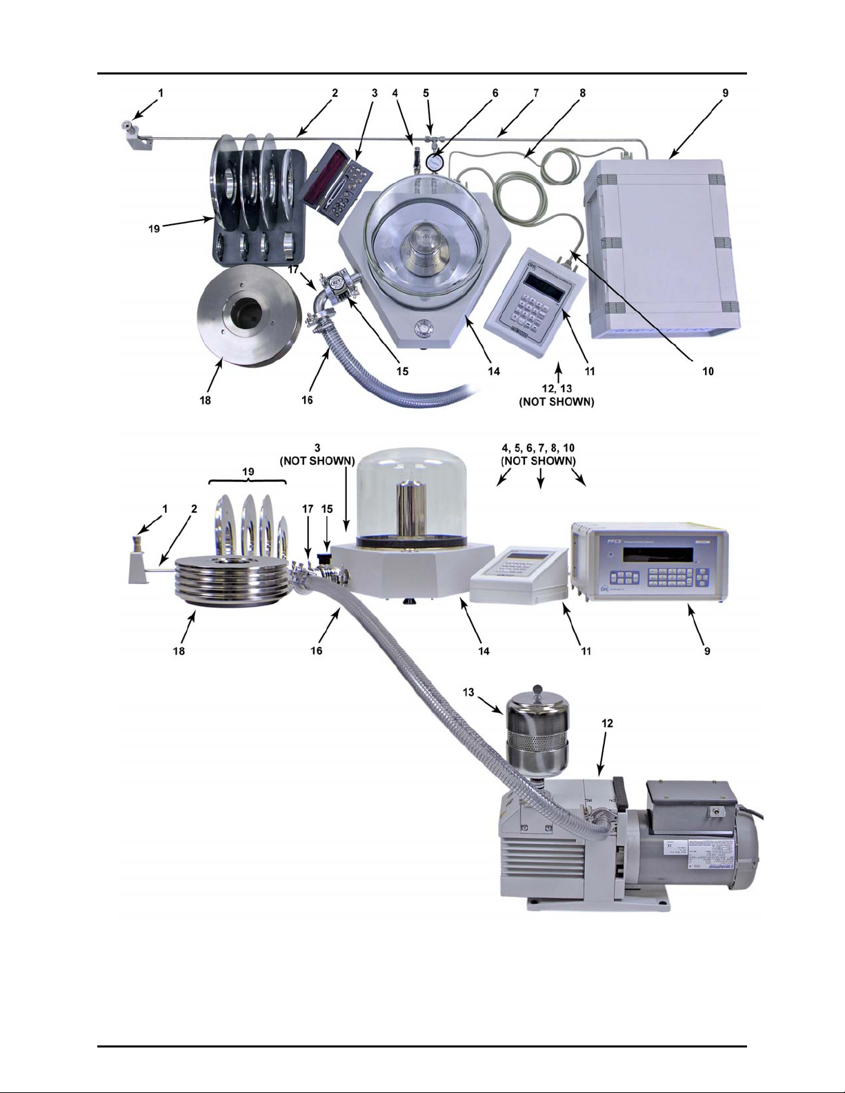
Figure 1. System, PG7601-SYS-AF, standard installation
Figure 2. System, PG7601-SYS-AF, system pneumatic schematic
Figure 3. System, PG7601-SYS-AF, electrical and communications schematic
Page 9 © 2007 DH Instruments, a Fluke Company
Page 24
PG7601-SYS-AF™ OPERATION AND MAINTENANCE MANUAL
1. DUT quick connector on stand
2. Tube, DUT connector to tee
3. Trim mass set
4. Vacuum vent valve
5. Tee
6. Platform shutoff valve
assembly
7. Tube, pressure controller to tee
8. RS232 cable, pressure
controller to platform
9. PPC3-7M-AF pressure
controller
10. PG Terminal to platform cable
11. PG Terminal
12. D16B reference vacuum
pump
13. Vacuum pump smoke
eliminator
14. PG7601-AF platform
15. Vacuum shutoff valve
16. KF25 hose
17. KF25 elbow
18. Main mass stack
19. Fractional mass tray
Figure 1. System, PG7601-SYS-AF, standard installation
© 2007 DH Instruments, a Fluke Company Page 10
Page 25
2. SYSTEM AND COMPONENT OVERVIEW AND DESCRIPTION
1. Test pressure supply
2. Pressure controller connection
3. Reference vacuum pump
4. Vacuum shutoff valve
5. Piston-cylinder module
6. Reference vacuum bell jar (removed in
gauge measurement mode)
7. DUT connection
8. Vacuum vent valve
9. Platform shutoff valve
10. Control vacuum supply
Figure 2. System, PG7601-SYS-AF, pneumatic schematic
1. Electrical power cords
2. PG Terminal to PG7601-AF platform data and
power connection
3. PG7601-AF platform to PPC3-7M-AF pressure
controller connection (RS232)
4. PG7601-SYS-AF system remote communications
(RS232)
5. PG7601-SYS-AF system remote communications
(IEEE-488)
Figure 3. System, PG7601-SYS-AF, communications schematic
Page 11 © 2007 DH Instruments, a Fluke Company
Page 26
PG7601-SYS-AF™ OPERATION AND MAINTENANCE MANUAL
2.2 PISTON GAUGE PLATFORM AND TERMINAL (PG7601-AF)
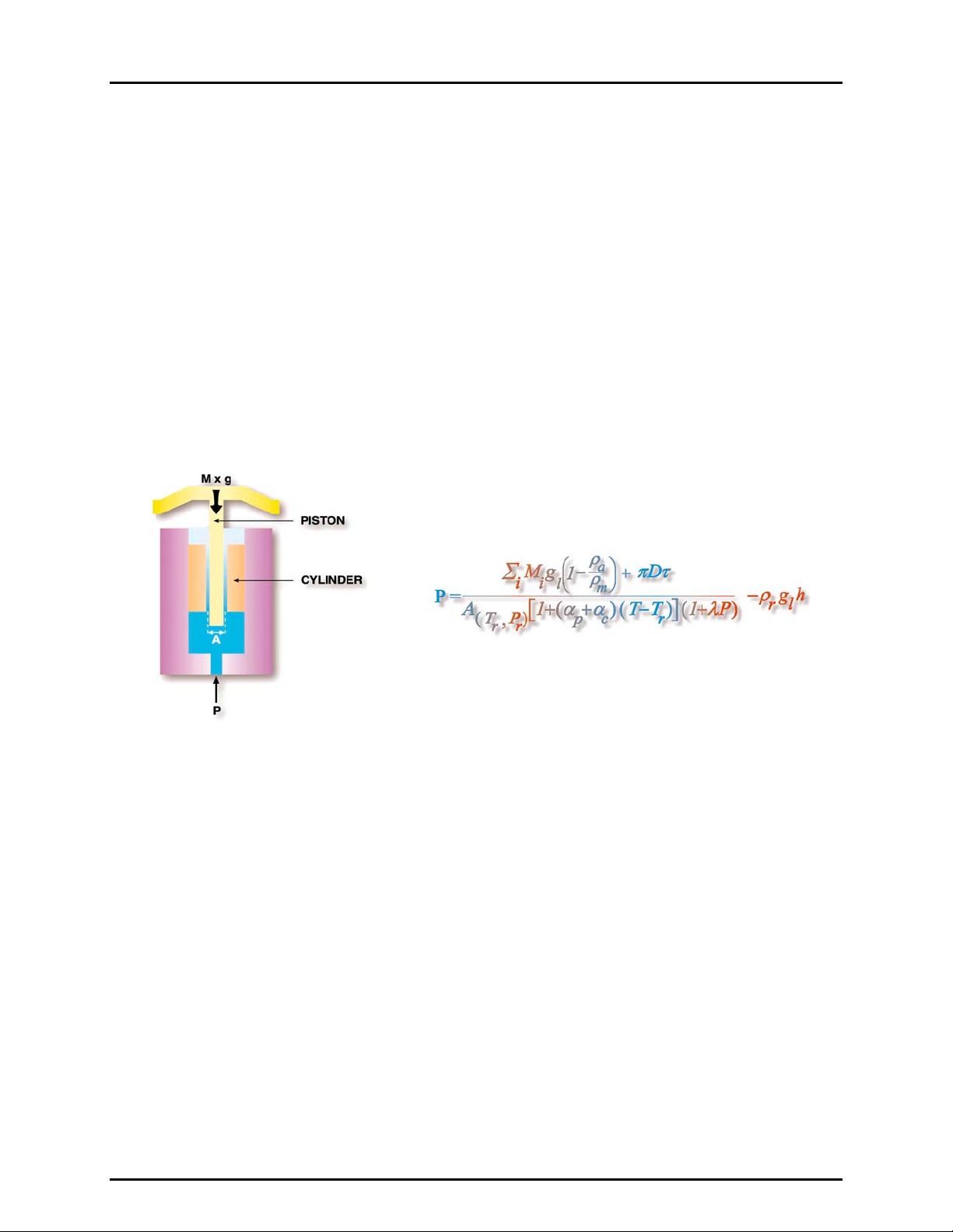
The heart of the PG7601-SYS-AF is the PG7601-AF gas operated piston gauge and its piston-cylinder
modules and mass set.
The PG7601-AF operates on the principle of the piston gauge in which pressure is defined by balancing it
against a known force on a known area (see Figure 4). The known area is defined by a vertically
mounted piston rotating in a cylinder and the known force is applied
mass subjected to acceleration due to gravity. When the force applied by the pressure and the force
appl ied by t he ma ss accelerated by gravity are in equilibrium, the piston floats and the pressure under the
piston remains constant. The pressure can be calculated following the equation in Figure 4. The
pressurized gas under the piston also lubricates the gap between the piston and the cylinder.
floating, the piston must be rotating to keep it well centered in the cylinder and perfectly mobile.
The system includes three piston cylinder modules and a 35 kg mass set. The combination provides
three ranges of 7 to 350 kPa (1 to 50 psi), 25 to 1750 kPa (3.6 to 260 psi) and 100 to 7 000 kPa (14.5 to
1000 psi). The PG7601-AF platform includes a bell jar that can be evacuated using the supplied
reference vacuum pump so that pressure can be defined against vacuum (absolute mode) or atmosphere
(gauge mode). The PPC3-7M-AF pressure controller adjusts pressure automatically or manually to float
the piston (see Section 4.1.2).
to the piston by loading it with known
When
Figure 4. Piston gauge operating principle
© 2007 DH Instruments, a Fluke Company Page 12
Page 27
2. SYSTEM AND COMPONENT OVERVIEW AND DESCRIPTION
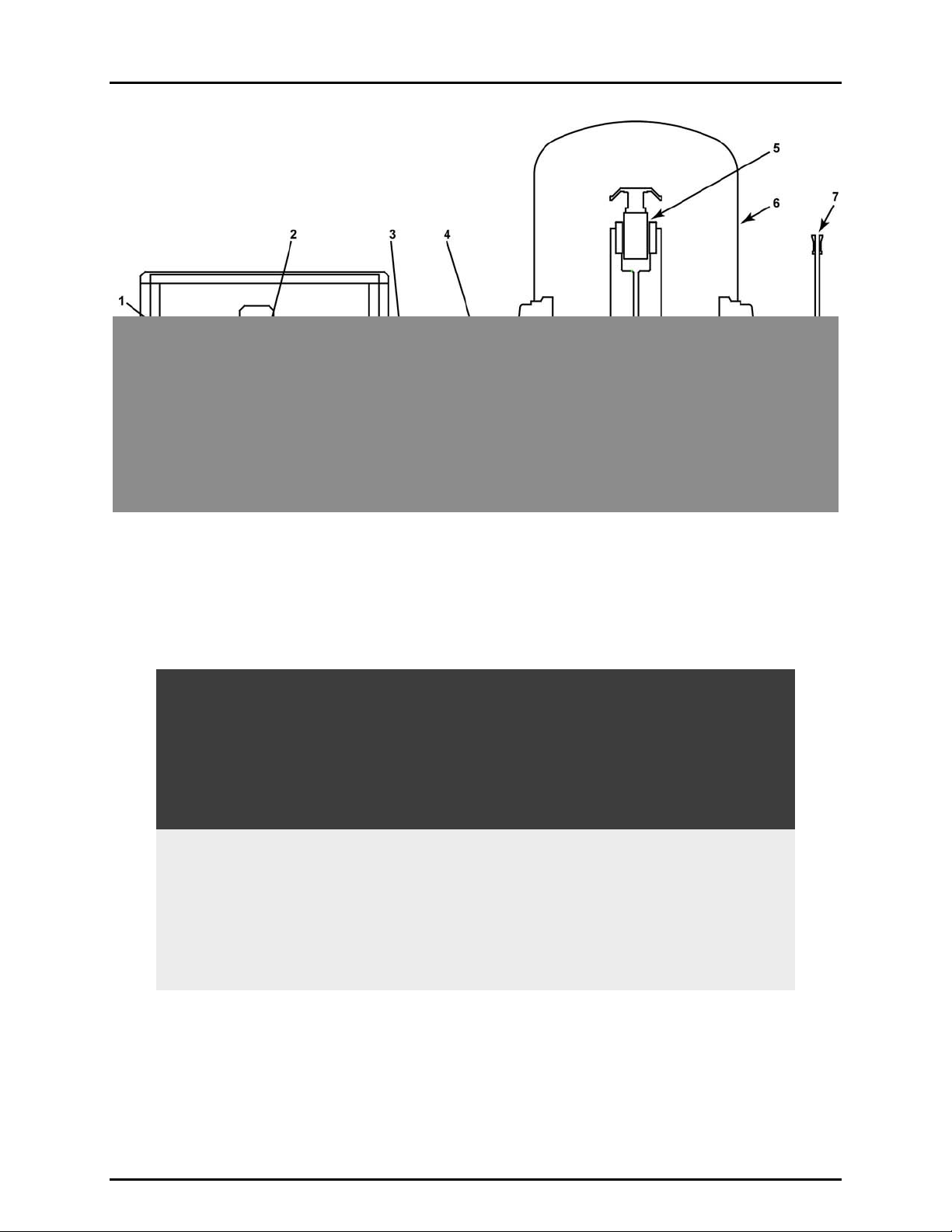
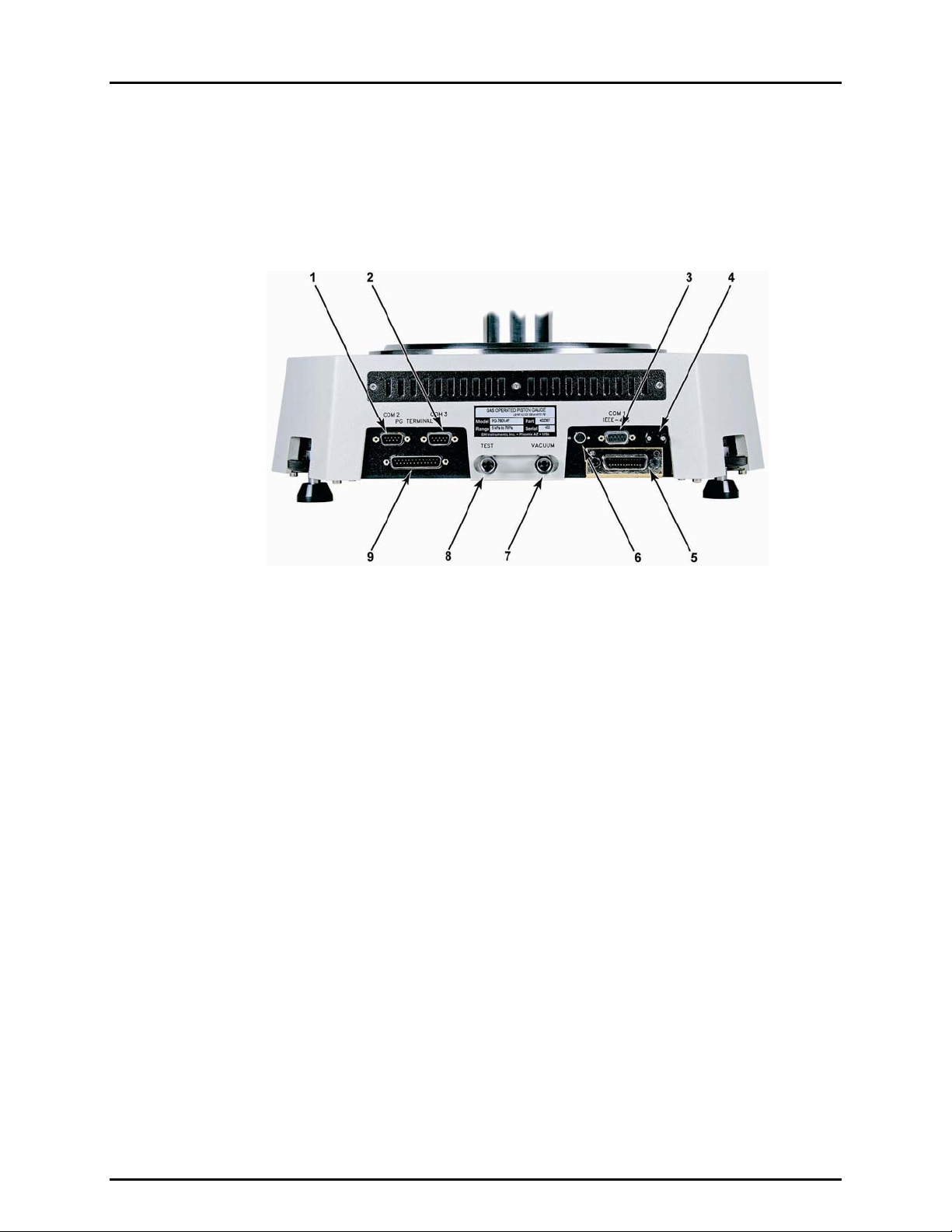
2.2.1 PLATFORM
The PG7601-AF platform is the instrument base into which the piston-cylinder modules are
mounted and onto which the masses are loaded. The platform also includes the electronic
measurement system.
The PG7601-AF platform rear panel provides the connection to the PG Terminal, remote
communication connections and pressure connection ports.
1. COM2 (RS232) for external barometer (optional), external
vacuum gauge (optional), pass through communications
2. COM3 (RS232) – for PPC3-7M-AF pressure controller,
AMH-38 automated mass handler (optional)
3. COM1 (RS232) - remote host communications
4. Ambient temperature sensor
Figure 5. Platform, PG7601-AF, rear view
5. IEEE-488 (GPIB) - remote host
communications
6. Ambient relative humidity sensor
7. VACUUM port, for vacuum vent valve
8. TEST port, for connection to test system
9. PG Terminal port
Page 13 © 2007 DH Instruments, a Fluke Company
Page 28
PG7601-SYS-AF™ OPERATION AND MAINTENANCE MANUAL
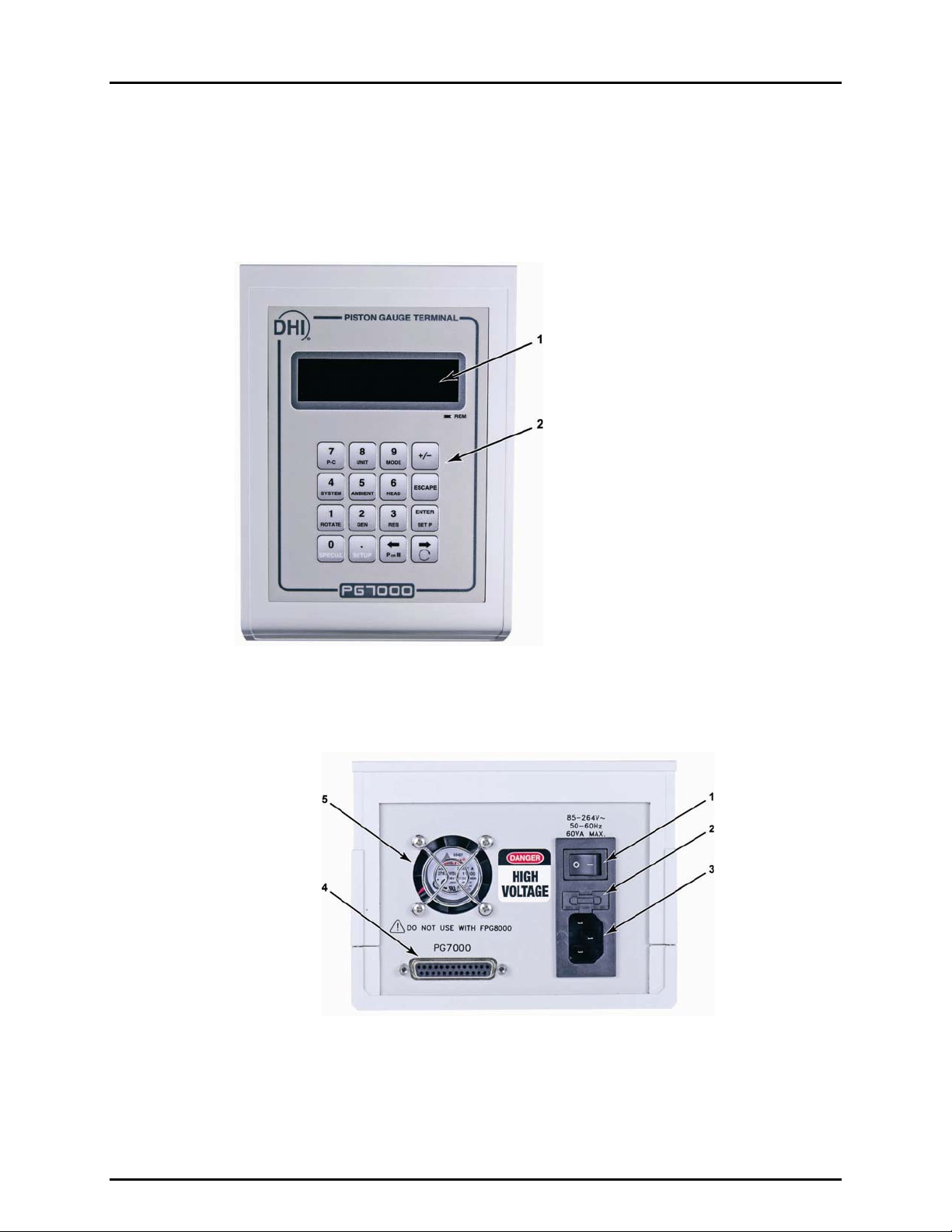
2.2.2 PG TERMINAL
The PG Terminal houses the PG platform power supplies and provides the local user
interface for interaction with the PG7601-SYS-AF system.
The front panel assembly provides a 2 x 20 vacuum fluorescent display and a 4 x 4
membrane keypad for local user interface.
1. Vacuum fluorescent display
2. Keypad
Figure 6. PG Terminal front panel
The PG Terminal rear panel assembly provides the communications connection to the
PG7601-AF platform and the power connection module.
1. Power switch
2. Fuse (25-pin)
3. Power receptacle
Figure 7. PG Terminal rear panel
4. Connector for cable to PG7000 platform
5. Cooling fan
© 2007 DH Instruments, a Fluke Company Page 14
Page 29
2. SYSTEM AND COMPONENT OVERVIEW AND DESCRIPTION
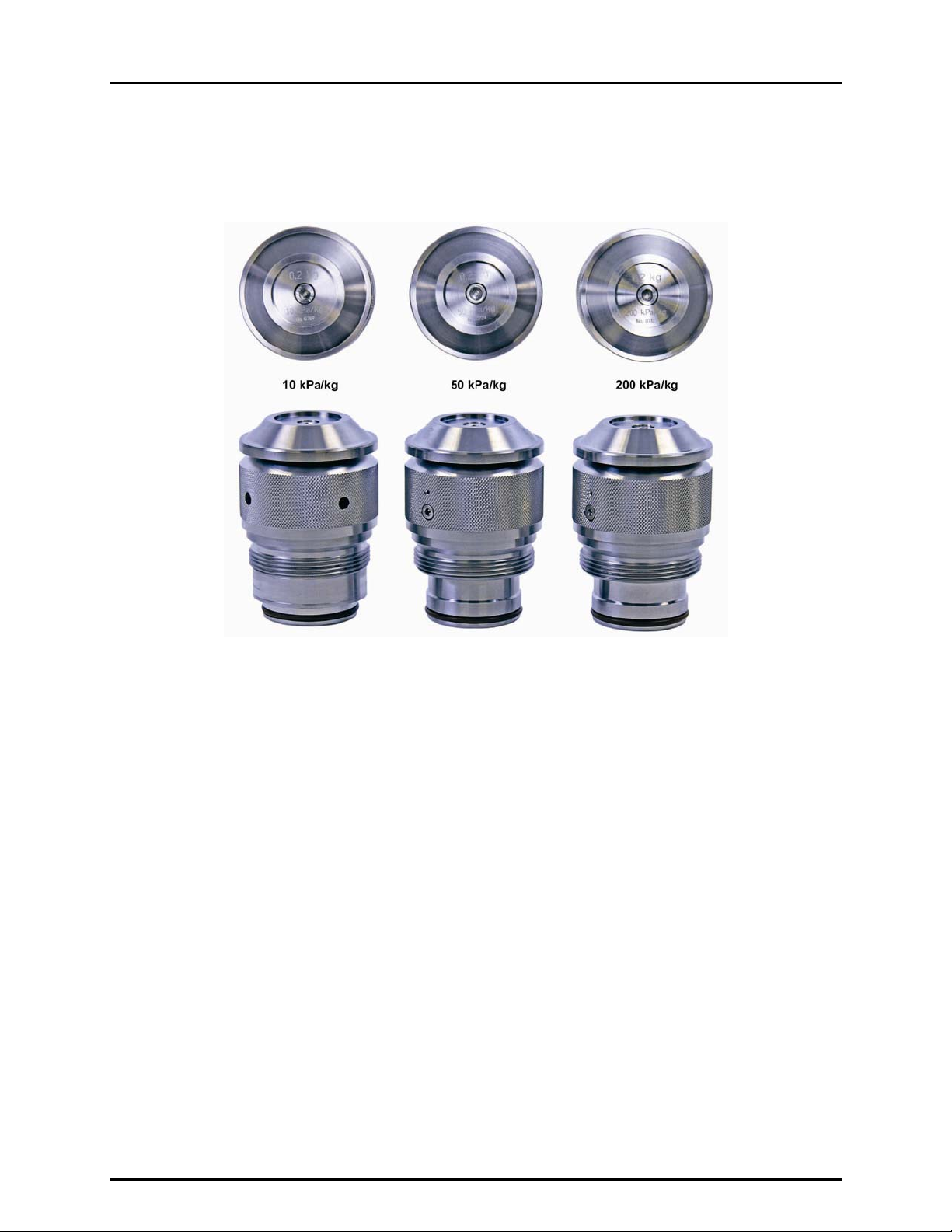
2.3 PISTON-CYLINDER MODULES (PC-7100/7600-10-L, -50, -200)
The piston-cylinder module is mounted in the PG7601-AF platform. The piston-cylinder precisely
converts pressure to a proportional force (see Section 4.1.1). There are three piston-cylinder modules for
three different pressure ranges.
Figure 8. Piston-cylinder modules, PC-7100/7600-10-L, -50, -200
Page 15 © 2007 DH Instruments, a Fluke Company
Page 30
PG7601-SYS-AF™ OPERATION AND MAINTENANCE MANUAL
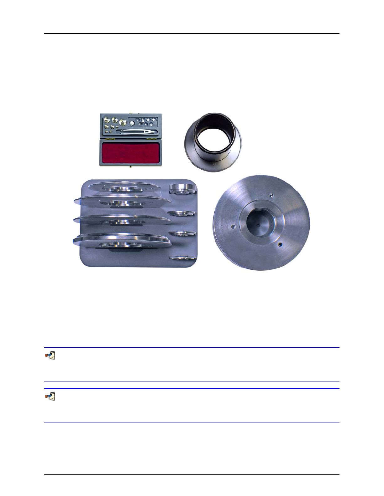
2.4 MASS SET (MS-7001-35-AF)
Combinations of masses from the 35 kg mass set are loaded onto in the piston-cylinder, as needed, to result
in the set pressure desired.
The mass set is made up of (1) mass loading bell of 0.3 kg, (1) 4.5 kg makeup mass disc, (5) 5 kg mass
discs, (2) 2 kg discs, (1) 1 kg disc, (1) 0.5 kg puck, (2) 0.2 kg puck, (1) 0.1 kg puck, 50 g to 0.01 g trim mass
set in 1-2-2-1 progression.
Figure 9. Mass set, MS-7100-35-AF
2.5 PRESSURE CONTROLLER (PPC3-7M-AF)
The PPC3-7M-AF pressure controller is used to set and adjust pressure in the PG7601-SYS-AF system.
Its operation can be fully automated to float the PG7601-AF’s piston under control of the PG7601-AF
platform’s AutoGen function (see Section 4.1.2). It can also be used manually under direct operator
control using its front panel direct pressure control keys.
The PPC3-7M-AF pressure controller is a component of the PG7601-SYS-AF system. It can also act as
a stand alone component. For information on use of PPC3-7M-AF outside of the PG7601-SYS-AF system, see
the PPC3 Operation and Maintenance Manual.
The pressure measurements made by the PPC3-7M-AF utility sensor are used only for pressure control
and indication. They have no metrological function therefore they do not require traceable calibration.
Adjustment of the PPC3 utility sensor is performed only for operational reasons (see Section 6.5).
© 2007 DH Instruments, a Fluke Company Page 16
Page 31

2. SYSTEM AND COMPONENT OVERVIEW AND DESCRIPTION
1. Ready/Not Ready indicator
2. Display
3. Remote activity indicator
4. Cursor control keys
5. Multi-function keypad
6. Direct pressure control keys
Figure 10. Pressure controller, PPC3-7M-AF, front panel
1. Label, product
2. VENT port
3. COM2 connector
4. IEEE-488 connector
5. COM1 connector (PG7601-AF
communications)
6. Drivers (12 V) connector
7. Power switch
8. Fuse
9. Electrical power connector (IEC-320-C13)
10. Remote [ENTER] connector
11. Pressure connection, TEST(+)
12. Pressure connection, TEST(-)
13. Pressure connection, EXHAUST
14. Pressure connection, SUPPLY
Figure 11. Pressure controller, PPC3-7M-AF, rear panel
Page 17 © 2007 DH Instruments, a Fluke Company
Page 32

PG7601-SYS-AF™ OPERATION AND MAINTENANCE MANUAL
2.6 REFERENCE VACUUM PUMP (D16B)
The reference vacuum pump is connected to the PG7601-AF platform reference vacuum port using the
PK-7601-V-AF vacuum interconnections kit. It is used to establish a vacuum under the platform’s
vacuum bell jar when operating in absolute measurement mode against a vacuum.
1. Smoke eliminator
2. Exhaust flange
3. Intake flange
4. Handle
5 Power switch
6. Oil fill plug
Figure 12. Reference vacuum pump, D16B, front and side views
7. Maximum oil fill line
8. Minimum oil fill line
9. Oil drain plug
10. Oil level sight glass
11. Gas ballast valve
© 2007 DH Instruments, a Fluke Company Page 18
Page 33

3. INSTALLATION
.
33.
I
NNSSTTAALLLLAATTIIOON
I
N
3.1 UNPACKING AND INSPECTION
3.1.1 UNPACKING AND INSPECTION OF PG7601-BAS-AF BASE SYSTEM
The PG7601-BAS-AF is the PG7601-SYS-AF gas piston gauge base system. It includes the
system operational components but not the piston-cylinder modules and mass sets which are
in the PG7601-EXC-AF exchange pack.
Check that all items included in the PG7601-BAS-AF base system are present and have NO
visible signs of damage.
Table 1 provides a parts list of the base system major components and how they are
Unpack and inspect the items following the instructions in Sections 3.1.1.1 to 3.1.1.6 and
detailed packing lists in Table 2 to Table 5.
Table 1. Base system, PG7601-BAS-AF, packing guide
COMPONENT SHIPPED IN SECTION
PG7601-AF platform and Terminal molded transit case 3.1.1.1 Table 2
PG7601-AF vacuum bell jar corrugated container 3.1.1.1 Table 2
PPC3-7M-AF pressure controller corrugated container 3.1.1.2 None
D16B reference vacuum pump corrugated container 3.1.1.3 None
Vacuum pump smoke eliminator 3.1.1.3 None
PK-7601-P-AF pressure
interconnections kit
PK-7601-V-AF vacuum
interconnections kit
PG7601-BAS-AF documentation and
accessories
corrugated container
3.1.1.4 Table 3
3.1.1.5 Table 4
3.1.1.6 Table 5
DETAIL
TABLE
packed.
3.1.1.1 PLATFORM, TERMINAL AND BELL JAR (PG7601-AF)
The PG7601-AF platform is shipped in a molded transit case with the PG7601AF Terminal and connecting cable. The vacuum bell jar is packed in a separate
double corrugated container.
To unpack proceed as follows:
Open the PG7601-AF shipping and storage case.
Remove the PG Terminal and its cable from the upper packing insert.
Remove the upper packing insert.
Carefully lift the PG7601-AF platform from its position in the lower packing
insert. Note the orientation so that the same orientation is used when
PG7601-AF is repacked.
Reinstall the upper packing insert into the shipping and storage case and store in a
safe place.
Page 19 © 2007 DH Instruments, a Fluke Company
Page 34

PG7601-SYS-AF™ OPERATION AND MAINTENANCE MANUAL
Carefully unpack the vacuum bell jar from its double packed corrugated
container. The bell jar is fragile. Set it aside where it is safe from damage.
Table 2. Platform, PG7601-AF, packing list
DESCRIPTION PART NO.
1 ea. PG7601-AF platform including: 402367
1 ea.
1 ea. PG7601-AF Terminal 401284
1 ea. Cable, DB25M x DB25F, PG Terminal to platform 102227
1 ea. Molded transit case (in which the platform is shipped) 122576
Bell jar and seal (in separate double corrugated container)
3.1.1.2 PRESSURE CONTROLLER (PPC3-7M-AF)
The PPC3-7M-AF pressure controller P/N 402014 is delivered in a corrugated
container with high density polyethylene inserts to hold it in place.
Remove the PPC3-7M-AF from the shipping container and remove it from its
protective plastic bag. There are no other items packed with the PPC3-7M-AF.
Remove the protective caps from the pressure controller rear panel and the
sheet of protective film from the front panel display. Install the rubber feet caps
included the accessories if desired (see Section 3.1.1.6)
122106 (bell jar)
101546 (seal)
3.1.1.3 REFERENCE VACUUM PUMP (D16B)
The D16B vacuum pump P/N 402058 is delivered in a corrugated container, held
in position by “foam in place”. The smoke eliminator for the vacuum pump is
packed with the accessories and interconnections kit (see Section 3.1.1.6).
3.1.1.4 PRESSURE INTERCONNECTIONS KIT (PK-7601-P-AF)
The PK-7601-P-AF pressure interconnections kit is delivered in a corrugated
container. Inventory all items following Table 3.
Table 3. Pressure interconnections kit, PK-7601-P-AF, packing list
DESCRIPTION P/N 402364
1 ea Valve assembly, platform shutoff (PG7601-AF TEST to
PG7601-AF tee)
1 ea. Custom 1/4 in. ss tube, 76 cm (30 in.) (PPC3-7M-AF to
PG7601-AF tee)
1 ea. Custom 1/4 in. ss tube, 53 cm (21 in.) (DUT connection to
PG7601-AF tee)
1 ea. Tee, 1/4 in. Swage (DUT connection to PPC3-7M-AF to
PG7601-AF TEST)
1 ea. Adaptor, 1/8 in. NPT M x 1/4 in. Swage 102033
1 ea. Quick connector on stand (DUT connection) 401459
1 ea. Quick connector stem, 1/4 in. NPT F 102117
1 ea. Quick connector stem, 1/8 in. NPT F 102116
1 ea. Quick connector stem, AN4 M 102115
1 ea. Quick connector stem, 1/4 in. Swage 101977
402361
402362
402363
102939
© 2007 DH Instruments, a Fluke Company Page 20
Page 35

3. INSTALLATION
3.1.1.5 VACUUM INTERCONNECTIONS KIT (PK-7601-V-AF)
The PK-7601-V-AF vacuum interconnections kit is delivered in a corrugated
container. Inventory all items following Table 4.
Table 4. Vacuum interconnections kit, PK-7601-V-AF, packing list
DESCRIPTION P/N 402365
1 ea. Valve, vacuum shutoff, KF25 102763
1 ea. Elbow, KF25 103736
1 ea. Vacuum hose, KF25, 48 in. 103737
2 ea. Clamp, KF25 102121
2 ea. Centering ring, KF25 101542
3.1.1.6 DOCUMENTATION AND ACCESSORIES
The PK-7601-BAS-AF accessories are delivered in a corrugated container.
Inventory all items following Table 5.
Table 5. Base system accessories kit packing list
DESCRIPTION P/N 402366
2 ea. Power cord, 7.5 ft. 100770
1 ea. Cable, null modem 402114
1 ea. Cable, RS232, 9 pin, 2m (PG7601-AF to PPC3-7M-AF) 100847
2 ea. O-ring, Buna 2-242 (PG7601-AF drive belts) 101976
1 ea. Dust cover, 7601 Type 102132
1 ea. Gloves, pair 101398
1 ea.
1 ea. Allen wrench, 2.5 mm 102257
1 ea. Allen wrench, 3 mm 102168
1 ea. Allen wrench, 5 mm 102262
1 ea. Piston insertion tool (10 kPa/kg) 402371
1 ea. Spanner wrench (piston-cylinder) 122568
1 ea. Mounting post PRT insertion plug 402389
1 ea. Valve assembly, vacuum relief, PG7601-AF platform with
1 set (6) Rubber feet caps (PPC3-7M-AF pressure controller) 400203
1 set Documentation
Krytox® GPL205/6 .5 oz.
instruction sheet
PG7601-AF Technical Data
PG7601-AF platform Calibration Report
PG7601-SYS-AF Operation and Maintenance Manual
PPC3-7M-AF Test Report
PG7601-SYS-AF Support Disc
102496
401050
550101
550100
550152
550161
402275
3.1.2 UNPACKING AND INSPECTION OF PG7601-EXC-AF EXCHANGE PACKAGE
The PG7601-EXC-AF is the PG7601-SYS-AF gas piston gauge system’s metrological
elements. It includes the piston-cylinder modules and mass set.
Check that all items included in the PG7601-EXC-AF exchange package are present and
have NO visible signs of damage.
Page 21 © 2007 DH Instruments, a Fluke Company
Page 36

PG7601-SYS-AF™ OPERATION AND MAINTENANCE MANUAL
Table 6 provides a parts list of the exchange package major components and how they are
packed. Unpack and inspect the items following the instructions in Sections 3.1.2.1 to 3.1.2.3
and detailed packing lists in Table 7 to Table 9.
Table 6. Exchange pack, PG7601-EXC-AF, packing guide
COMPONENT SHIPPED IN SECTION
PC-7100/7600-10-L, -50 and 200 piston-cylinder modules
and accessories
MS-7001-35-AF mass set (2) molded transit
PG7601-EXC-AF
documentation and accessories
(3) bullet cases
inside a single
molded transit case
cases
Corrugated
container
3.1.2.1 Table 7
3.1.2.2 Table 8
3.1.2.3 Table 9
DETAIL
TABLE
3.1.2.1 PISTON-CYLINDER MODULES (PC-7100/7600-10-L,
PC-7100/7600-50, PC-7100/7600-200) AND
ACCESSORIES
The piston-cylinder modules are shipped in PVC bullet cases that are packed in
a reusable transit case with foam inserts. The piston-cylinder module
accessories are packed in a recess in the transit case.
Open the transit case and remove the piston-cylinder module bullet cases and
accessories.
The bullet cases screw open by turning the lid counterclockwise.
Table 7. Piston-cylinder modules, PC-7100/7600-10-L, PC-7100/7600-50,
PC-7100/7600-200, packing list
DESCRIPTION P/N
1 ea. PC-7100/7600-10-L piston-cylinder module in bullet case 402184
1 ea. PC-7100/7600-50 piston-cylinder module in bullet case 401563
1 ea PC-7100/7600-200 piston-cylinder module in bullet case 401564
3 ea. Piston-cylinder module bullet case 401642
1 ea. Molded transit case for three piston –cylinder modules 402368
1 ea. O-ring, Viton, brown, 2-122 101918
2 ea. O-ring, Vitron, brown, 2-120 101921
3 ea. O-ring, Viton, brown, 2-130 102380
3.1.2.2 MASS SET (MS-7001-35-AF)
The stability over time of PG7601-AF pressure measurements is a function of
the stability of the masses loaded on the piston. Precautions should be taken in
handling the masses to minimize influences that may change their mass. This
includes always wearing protective gloves when handling the masses to avoid
contaminating them with body oils and perspiration. Protective gloves are provided
in the mass set accessory kit.
The PG7601-AF mass set is shipped in (2) molded transit cases. The masses
should be removed from their shipping cases and inventoried when actually
setting up the PG7601-AF system.
To unpack: Carefully remove each mass from the transit case. Do not remove
masses from their plastic bags until ready to install them (see Section 3.3.4).
© 2007 DH Instruments, a Fluke Company Page 22
Page 37

3. INSTALLATION
Table 8 details the the MS-7001-35-AF mass set.
Table 8. Mass set, MS-7001-35-AF, packing list
DESCRIPTION P/N 402259
1 ea. 4.5 kg make up mass disk 123334
5 ea. 5 kg mass disk 123213
2 ea 2 kg mass disk 121922
1 ea. 1 kg mass disc 121936
1 ea. 0.5 kg mass puck 123500
2 ea. 0.2 kg mass puck 123498
1 ea. 0.1 kg mass puck 123496
1 ea. 0.3 kg mass loading bell 402135
1 ea. Trim mass set (50 to 0.01 g) in case 402403
1 ea. Main mass molded transit case with inserts 123057
1 ea. Fractional mass modled transit case with inserts 122577
3.1.2.3 DOCUMENTATION AND ACCESSORIES
The PG7601-EXC-AF exchange pack accessories and documentation are
shipped in a separate corrugated container. Open the corrugated container and
inspect and inventory the contents.
Table 9 details the PG7601-EXC-AF exchange pack accessories and
documentation.
Table 9. Exchange pack accessories packing list
DESCRIPTION P/N (PART OF 402259)
1 ea. Fractional mass tray 123051
1 ea. Main mass spindle 123536
1 ea. Fractional mass tray dust cover 102814
1 ea. Main mass stack dust cover 102847
1 ea. Gloves, pair 101398
4 ea. Calibration report (mass set and (3) piston-cylinder
modules)
4 ea. Metrology Support Disk 550300
550100
3.2 SITE REQUIREMENTS
See Section 2.1, Figure 1 for an illustration of the PG7601-SYS-AF standard installation.
When selecting and preparing a site to set up the PG7601-SYS-AF system, the following should be
considered:
• Ambient conditions: To achieve optimum metrological performance, ambient conditions should be
controlled and maintained within the following:
♦ Temperature: 19 to 23 °C, minimize rate of change of temperature.
♦ Relative Humidity: 10 to 60 %RH (non-condensing).
♦ Ambient Pressure: Minimize external influences that will cause barometric instability.
Page 23 © 2007 DH Instruments, a Fluke Company
Page 38

PG7601-SYS-AF™ OPERATION AND MAINTENANCE MANUAL
♦ Air Currents: Do not install the PG7601-AF platform under a source of vertical air currents such as
an overhead air conditioning duct. These can blow on the mass load and add unquantified forces.
♦ Vibration: Minimize local vibration. Excessive vibration will reduce the stability of the pressures
defined by PG7601-AF (vibration affects the floating piston). Excessive high frequency vibration, for
example from a vacuum pump on the same table as the PG7601-AF, may affect piston sensitivity.
• Bench space: The recommended standard setup for the PG7601-SYS-AF system requires a bench
space of at least 165 cm x 56 cm (65 in. x 22 in.) (see Section 2.1, Figure 1).
• Bench stability
: Up to 36 kg (79 lb) may be loaded and unloaded onto the PG7601-AF
platform.
The bench on which the PG7601-AF sits should not deflect significantly under the mass load
changes. This can be verified by setting the platform on the bench, leveling it using its bubble level,
and loading and unloading the complete mass set while observing whether the level setting changes.
• Location of other components: Plan the space required and a convenient layout for the complete
PG7601-SYS-AF system including the PG Terminal, mass set, pressure controller, reference vacuum
connection and pump location and test instrument connection. There is a recommended standard setup
for the system (see Section 2.1, Figure 1). This setup may be used or the setup may be customized.
If customizing the physical set up of the PG7601-SYS-AF system, follow these recommendation:
- The pressure connection between the test connection (to DUT) and the PG7601-AF
platform
should be direct, with no components in between. The pressure controller
should NOT be connected between the PG7601-AF platform and the test connection.
- Minimize tubing lengths between the components.
- Do no use fittings, adaptors or components that will restrict flow in the system more
than the components provided with the PK-7601-P-AF interconnections kit.
- Avoid low points or potential liquid traps between the PG7601-AF platform and the
DUT connection.
- Be sure the surface on which the PG7601-AF platform is installed is isolated from the
D16B vacuum pump vibration.
- Consider drilling a 4 in. hole in the bench to run the KF25 vacuum connection straight
down through the bench to the vacuum pump.
• Electrical supply: Plan the supply of electrical power to the PG Terminal and to the pressure
controller.
• Test gas supply: Plan the supply of test gas to the pressure controller. The test gas supply must be
clean and dry (instrument grade minimum, high purity preferred) to avoid contaminating the pistoncylinder gap (see Section 3.3.7).
• Control v
acuum supply
: Plan the supply of control vacuum to the pressure control. The control
vacuum supply must be separate from the reference vacuum supply (see Section 3.3.8).
• Reference vacuum supply
: Plan for the vacuum connection to the platform and the location of the
reference vacuum pump. There is a recommended standard setup for the system (see Section 2.1,
Figure 1). This setup may be used or the setup may be customized.
• Bell jar placement: Plan a location for the bell jar when it is
removed from the platform to load and
unload masses or when operating in gauge mode. The bell jar may be placed on top of the pressure
controller.
© 2007 DH Instruments, a Fluke Company Page 24
Page 39

3. INSTALLATION
3.3 PHYSICAL SETUP
Before setting up the PG7601-AF system, see Section 2.1, Figure 1 for an illustration of the PG7601-
SYS-AF standard installation and Section 3.2 for information on site requirements.
To set up the PG7601-SYS-AF components for operation proceed as follows in the specified order:
Set up the PG7601-AF platform (see Section 3.3.1).
Set up the PPC3-7M-AF pressure controller (see Section 3.3.2).
Make the system pressure interconnections (see Section 3.3.3).
Set up the MS-7001-35-AF mass set (see Section 3.3.4)
Install a piston-cylinder module into the platform (see Section 3.3.5).
Set up the D16B vacuum pump and make the system vacuum interconnections (see Section 3.3.6).
Connect test gas supply (see Section 3.3.7).
Connect control vacuum supply (see Section 3.3.8).
3.3.1 SETTING UP THE PLATFORM
Before setting up the PG7601-AF system, see Section 2.1, Figure 1 for an illustration of the
PG7601-SYS-AF standard installation and Section 3.2 for information on site requirements.
To set up the PG7601-AF platform proceed as follows:
Place the PG7601-AF platform on the site table in the desired orientation and location
(see Section 2.1, Figure 1). Though the rear panel is usually in the back, any orientation
can be used.
Place the PG7601-AF Terminal at the desired location.
Connect the PG7601-AF Terminal to the PG7601-AF platform using the 25 pin cable
supplied.
Connect electrical power (85 to 264 VAC, 50/60 Hz) to the PG7601-AF Terminal using
the power cable supplied. Any grounded power cable with a standard IEC320-313
connection may be used.
Install the vacuum vent valve on the vacuum vent port on the rear of the PG7601-AF
platform. Refer to the instruction sheet provided with the vent valve assembly.
Level the platform using the PG7601-AF platform’s two front leveling feet and the bubble
level mounted on the front of the platform.
Page 25 © 2007 DH Instruments, a Fluke Company
Page 40

PG7601-SYS-AF™ OPERATION AND MAINTENANCE MANUAL
3.3.2 SETTING UP THE PRESSURE CONTROLLER
Refer to Section 2.1, Figure 1 for an illustration of the PG7601-SYS-AF standard
installation and Section 3.2 for information on site requirements.
To set up the PPC3-7M-AF pressure controller proceed as follows:
Install the rubber feet caps on the PPC3-7M-AF if desired.
Place the pressure controller at the desired location.
Connect electrical power (85 to 264 VAC, 50/60 Hz) to the pressure controller using the
power cable supplied. Any grounded power cable with a standard IEC320-313
connection may be used.
Connect and secure the 9 pin, RS232 cabl e supplied between the PPC3-7M-AF COM1
port and the PG7601-AF platform COM3 port.
3.3.3 SYSTEM PRESSURE INTERCONNECTIONS
This section assumes that the PG7601-AF system will be setup using the PK-7601-P-AF
interconnections kit following the standard installation described in Section 2.1, Figure 1. Custom
installations are also possible. Before considering a customer installation, see Section 3.2 for setup
cautions and recommendations.
Use the PK-7601-P-AF interconnection kit (see Section 3.1.1.4) to interconnect the
PG7601-SYS-AF system components as follows. Refer to Section 2.1, Figure 1.
Install the platform shutoff valve assembly onto the PG7601-AF TEST port. Use the
gland and collar that are delivered installed in the TEST port. Set aside the orange plug
and install the gland and collar onto the DH200M end of the assembly. Be sure the collar
is fully threaded (left hand thread). Then install the assembly into the TEST port by
tightening the gland.
Install the 1/4 in. Swage tee onto the platform shutoff valve assembly. Finger tighten only.
Install the 1/8 in. NPT M x 1/4 in. Swage adaptor into the TEST(+) port of the
PPC3-7M-AF. Use Teflon
®
tape or other thread sealer on the 1/8 in. NPT M threads.
Connect the “PPC3-7M-AF to tee” 1/4 in. stainless steel tube to the Swage tee. Finger
tighten only.
Connect the “PPC3-7M-AF to tee” 1/4 in. stainless steel tube to the adaptor on the
PPC3-7M-AF TEST(+) port. Tighten firmly.
Connect the “DUT quick connector on stand to tee” 1/4 in. stainless steel tube to the DUT
quick connector. Tighten firmly.
Connect the “DUT quick connector on stand to tee” 1/4 in. stainless steel tube to the
Swage tee.
Tighten all three nuts on the Swage tee firmly.
Secure DUT quick connector stand to bench top if desired (screws not provided).
© 2007 DH Instruments, a Fluke Company Page 26
Page 41
3. INSTALLATION
3.3.4 SETTING UP THE MASS SET
Place the mass loading tray and mass spindle (provided with the mass set accessories) at
the desired location (see Section 2.1, Figure 1). Then follow the steps below:
The stability over time of PG7601-AF pressure measurements is a function of the stability
of the masses loaded on the piston. Precautions should be taken in handling the masses to
minimize influences that may change their mass. This includes always wearing protective gloves
when handling the masses to avoid contaminating them with body oils and perspiration.
Protective gloves are provided with the mass set accessories.
It is VERY IMPORTANT that the individual masses be installed on the mass loading tray in
proper sequence. This will ensure that PG7601-AF mass loading instructions are executed
properly (carefully follow the instructions provided in this Section).
To install the masses on the mass loading tray, proceed as follows:
PG7601-AF masses are shipped in reusable, molded shipping and storage cases. One
of the cases contains a 4.5 kg mass and the masses of 2 kg and under. The other case
contains the main masses of 5 kg each. Each mass is packed in a sealed plastic bag and
then placed in a protective shipping insert.
If the masses have not yet been inventoried, open the shipping cases and identify the
masses (see Section 3.1.2.2). Remove each mass from its
plastic
bag as you install it on
the spindle or tray.
Install the main masses: The main masses are a series of 5 kg masses numbered 1 to 5.
Pile the main masses onto the main mass spindle. Put mass number 5 at the bottom of the
stack. Then pile in descending order: 5, 4, 3, 2, 1, bottom to top. Be careful NOT to confuse
the 4.5 kg makeup mass with a 5 kg mass (refer to next step with main mass 1).
Install the make up mass: The ma ke up mass is a single 4.5 kg mass numbered 1. It
has the same diameter as the main masses.
The make up mass is installed vertically in the corresponding slot on the mass loading tray.
Install the fractional masses: The fractional masses are all the masses of 2 kg and
under. Fractional masses of 2 and 1 kg are discs with a central hole. Fractional masses
of 100 to 500 g are solid, small diameter pucks. Fractional masses of 50 g and under are
trim masses packed and stored in their own separate case.
Fractional mass discs and pucks are installed vertically in the corresponding slots in th e mass
loading tray. Note that there are (2) 2 kg masses numbered 1 and 2. When used, these
are always loaded first 1, then 2.
The trim mass case can be placed near the mass tray as desired.
Install the mass set dust covers (included in mass set accessories) if desired.
Page 27 © 2007 DH Instruments, a Fluke Company
Page 42

PG7601-SYS-AF™ OPERATION AND MAINTENANCE MANUAL
3.3.5 INSTALLING A PISTON-CYLINDER MODULE INTO THE PLATFORM
To operate the PG7601-AF system, a piston-cylinder module must be installed in the
platform’s mounting post. To install a piston-cylinder module in the PG7601-AF platform,
proceed as follows:
Remove the PG7601-AF platform mounting post plug. Unscrew the ORANGE plastic
mounting post plug that is installed in the platform mounting post. Rotate
counterclockwise to remove.
Remove the piston-cylinder module from its bullet case. Select a piston-cylinder module.
Open the piston-cylinder module bullet case by rotating its lid counterclockwise. Remove the
piston-cylinder module from the bullet case base by unthreading it from the case. Hold the
piston-cylinder module body by the knurled area and rotate it counterclockwise.
Place the piston-cylinder module in the PG7601-AF platform mounting post. Place the
piston-cylinder module (thread down) into the platform mounting post (see Figure 13 below).
Screw the piston-cylinder module into the PG7601-AF platform mounting post.
Rotate the piston-cylinder module clockwise until all threads are engaged and there is
NO gap between the piston-cylinder module and the mounting post. Slight resistance will
be encountered in the second half of travel as the piston-cylinder module O-rings seat in
the mounting post.
Make the installed piston-cylinder active in the PG7601-AF platform. Use [P-C] to
select the piston-cylinder that was installed in the steps above (see Section 4.3.2). If no
piston-cylinder module
digital ID has yet been created in PG7601-AF platform memory, it
is not possible to select one and [P-C] results in an error message. In this case, see
Section 4.5.1.1 to create or install a piston-cylinder digital ID.
To remove a piston-cylinder module from the platform, simply unthread it (counter
clockwise)
from the mounting post and return it to its bullet case.
Figure 13. Piston-cylinder module installation
Low torque manual rotation is all that should be required to fully seat the piston-cylinder
module into the PG7601-AF mounting post. Never force the piston-cylinder module into the
mounting post.
© 2007 DH Instruments, a Fluke Company Page 28
Page 43

3. INSTALLATION
3.3.6 SETTING UP THE REFERENCE VACUUM PUMP AND
VACUUM INTERCONNECTIONS
Refer to Section 2.1, Figure 1 for an illustration of the PG7601-SYS-AF standard
installation and identification of components. See Section 2.6 for detail on the D16B vacuum
pump. See Section 3.2 for information on site requirements.
To set up the D16B reference vacuum pump and connect it to the PG7601-AF platform
proceed as follows:
Install the smoke eliminator on the D16B vacuum pump. Orient the D16B vacuum
pump exhaust connection vertically. Remove the four capscrews, rotate the exhaust
flange and reinstall the cap screws.
Remove the KF25 clamp, centering ring and rubber cover from the exhaust connection.
Use the clamp and centering ring to install the smoke eliminator (the smoke eliminator is
delivered with the PG7601-BAS-AF accessories).
Place the D16B vacuum pump in the desired location. The vacuum pump needs to
able to be reached by the 48 in. KF25 vacuum hose provided in the vacuum
interconnections. The pump should not be installed on the same surface as the PG7601AF platform to avoid vibration of the operating pump affecting the platform.
Connect the pump’s electrical cord to a power supply (85 to 264 VAC, 50/60 Hz). Note
that pump has 1430 VA max. consumption that peaks on start up. A dedicated,
“industrial rated” (slow blow) breaker may be needed to avoid an overload at start up.
Connect the vacuum shutoff valve to the PG7601-AF platform. Remove the KF25
vacuum clamp, centering ring and plug from the PG7601-AF platform’s KF25 vacuum
connection. Use the KF25 clamp and centering ring to install the valve onto the
platform’s vacuum port. Orient the valve so that it can be operated conveniently.
Connect the vacuum elbow to the vacuum shutoff valve. Use a KF25 clamp and
centering ring to connect the 90° KF25 elbow to the vacuum shutoff valve installed in
step
. Orient the elbow so that it can be connected to the 48 in. vacuum hose that
connects to the vacuum pump.
Connect the 48 in. vacuum hose between the elbow and the vacuum pump. Use a
KF25 clamp and centering ring to connect the 48 in. vacuum hose to the 90° KF25 elbow
that was installed in step
.
Remove the vacuum clamp, centering ring and plastic cover from the DB16B vacuum
pump inlet port. Leave the protective screen in place. Use the clamp and centering ring
to attach the 48 in. vacuum hose to the vacuum pump.
3.3.7 CONNECTING TEST GAS SUPPLY
Using a pressure connecting hose or tube of appropriate pressure rating, connect the
pressure supply to the SUPPLY port on the rear panel of PPC3-7M-AF. The PPC3 SUPPLY
port connection is 1/8 in. NPT female.
The PPC3 SUPPLY port is aluminum. When installing the 1/8 in. NPT M adaptor (not
included), take care not to cross thread it and damage the port threads.
The supply pressure should be equal to the maximum PPC3-7M-AF control pressure + 10 %.
This is normally 7.7 MPa (1100 psi). A lower gas pressure supply can be used but should
exceed the maximum desired test output pressure by 10 to 20 %. The supplied gas must be
Page 29 © 2007 DH Instruments, a Fluke Company
Page 44

PG7601-SYS-AF™ OPERATION AND MAINTENANCE MANUAL
clean, dry (instrument grade) nitrogen, air or helium. Using an unclean or moist gas supply
will increase piston-cylinder cleaning frequency.
Never connect a pressure supply greater than 8.4 MPa (1200 psi). Be sure to connect the
pressure supply to the SUPPLY port. Connecting to another port is likely to damage PPC3-7M-AF.
3.3.8 CONNECTING CONTROL VACUUM SUPPLY
For the PPC3-7M-AF to set pressure under atmosphere and/or to reliably set pressure under 20
kPa (3 psi) gauge (other than zero gauge), a vacuum supply must be connected to the
EXHAUST port.
The control vacuum supply is not included in the PG7601-AF system. For full PG7601-AF
system operation, the control vacuum must be provided by a vacuum source with an ultimate
pressure lower than 2 kPa (0.3 psia) and flow of at least 85 slm (3 cfm). The control vacuum
supply should be separate from the PG7601-AF reference vacuum supply. Do not tee off the
D16B reference vacuum pump to supply vacuum to the PPC3-7M-AF EXHAUST port. The
flow through the EXHAUST port will have an adverse effect on the reference vacuum.
Using a vacuum hose or tube, connect the pressure supply to the EXHAUST port on the rear
panel of PPC3-7M-AF. The PPC3 EXHAUST port connection is 1/4 in. NPT female.
Never connect a pressure supply to or plug the PPC3-7M-AF EXHAUST port.
To avoid building up pressure on the EXHAUST port or on a vacuum pump connected to the
EXHAUST port, the vacuum source should either be continuously ON or the EXHAUST port should
be bypassed to atmosphere when the vacuum source is OFF. This is because when a supply
pressure is applied to the PPC3-7M-AF SUPPLY port and the PPC3 is NOT in the vent ON
condition, there may be a constant gas exhaust through the PPC3 EXHAUST port.
3.4 POWER UP AND VERIFICATION
This section assumes that the physical setup of the PG7601-SYS-AF system has been completed (see
Section 3.3).
3.4.1 POWER UP PLATFORM AND PRESSURE CONTROLLER
Turn the PG7601-AF power ON by pressing the power ON/OFF switch on the rear panel of the
PG Terminal. Observe the PG terminal display as the terminal connects with the PG7601-AF
platform, initializes, error checks and goes to the MAIN run screen (see Section 4.2.1.2).
…
.Searching…..> displays for more than 10 seconds, communication between the
If <
platform and the PG Terminal is failing. Check that the platform to PG Terminal cable is
properly installed.
Turn the PPC3-7M-AF power ON by pressing the power ON/OFF switch on its rear panel.
Observe the front panel display as PPC3-7M-AF initializes, error checks and goes to the
MAIN run screen (see Section 4.2.1.2).
If either product fails to reach the MAIN run screen, service may be required. Record the
sequence of operations and displays observed and contact a DHI Authorized Service Provider.
© 2007 DH Instruments, a Fluke Company Page 30
Page 45

3. INSTALLATION
3.4.2 CHECK THAT ON-BOARD PISTON-CYLINDER MODULE
AND MASS SET DIGITAL ID
PG7601-AF uses stored piston-cylinder and mass set metrological information to calculate
the reference pressures it defines (see Section 4.1.1). This information is stored in digital
identification records (digital IDs) (see
the stored metrological information of the piston-cylinder, mass set and mass loading bell
must be correct. Before using the PG7601-AF system, the validity of the
should be verified. Verification consists of comparing the piston-cylinder, mass set and mass
loading bell information stored in the PG7601-AF platform to the information in the current
piston-cylinder, mass set and mass loading bell calibration reports.
To verify the PG7601-AF piston-cylinder, mass set and mass loading bell information, use
the piston-cylinder and mass set viewing capabilities accessed by pressing [SPECIAL],
<1PC/MS> (see Section 4.5.1). Compare all the information contained in the PG7601-AF
mass
piston-cylinder,
cylinder, mass set and mass loading bell calibration reports delivered with the system.
If piston-cylinder or mass set information is incorrect or missing, it can be entered manually
(see Section 4.5.1) or loaded remotely from a personal computer using the digital ID
files supplied on the element’s Metrology Support Disk (see Section 7.4).
set and mass loading bell digital IDs to the information on the piston-
Section 4.5.1). For the pressure values to be correct,
S ARE CORRECT
stored information
(*.did)
3.4.3 SET LOCAL GRAVITY VALUE
PG7601-AF uses the value of local acceleration due to gravity (gl) in its calculation of the
reference pressure it defines (see Section 4.1.1). The correct value of local acceleration due to
gravity at the site of use must be entered. This is accomplished by pressing [SPECIAL], <6gl
(see Section 4.5.6) and editing the value of local gravity. To access and edit the value of <6gl
is first necessary for the PG7601-AF platform security level
[SPECIAL], <4prefs>, <5level>, <1set user level> (see Section 4.5.4.5). After changing the
o
user level <none> t
access <6gl>, be sure to set it the user level back to <low>.
to be set to <none> using
>
> it
3.4.4 CHECK/SET SECURITY LEVEL
PG7601-AF has a security system based on user levels. By default, the security system is
set to “low”, which includes certain access restrictions, and there is no password required to
change the security level. See Section 4.5.4.5 for information on the security level system.
As part of the system startup, determine the security level that is
password if desired.
The PG7601-AF platform is delivered with the security level set to low to avoid inadvertent
altering of critical internal settings but with access to changing security levels unrestricted. It is
recommended that the low security level be maintained at all times and password protection be
implemented if control over setting of security levels is desired.
appropriate
and set a
3.4.5 CHECK PROPER OPERATION OF AMBIENT CONDITION
MEASUREMENTS
PG7601-AF automatically measures ambient conditions and uses the values in its pressure
calculations.
To verify that the ambient condition measurements are operating properly, proceed as follows:
• Display current ambient condition readings: Press [AMBIENT] on the PG7601-AF
Terminal. The ambient conditions run screen is displayed (see Section 4.3.6).
Page 31 © 2007 DH Instruments, a Fluke Company
Page 46

PG7601-SYS-AF™ OPERATION AND MAINTENANCE MANUAL
• Verify proper ambient condition readings: Compare the ambient condition values
displayed to the actual values of ambient conditions. Refer to the ambient condition
measurement specifications when evaluating the ambient readings (see Section 1.1.2.2).
The unit of measure in which ambient pressure is displayed is the same as the unit selected
by pressing [UNIT] (see Section 4.3.3). Units of measure in which other ambient condition values
are expressed cannot be changed.
PG7601-AF allows the source of ambient condition values used in reference pressure
calculations to be specified. The source may be PG7601-AF’s on-board measurements, default
values or operator entered values. See Section 4.4 for information on specifying the source of
ambient condition values used by PG7601-AF in reference pressure calculations.
3.4.6 TURN ON AUTOGEN AND AUTOROTATE
In most cases, PG7601-AF is operated with the AutoRotate and AutoGen functions ON so
that the piston is automatically rotated when necessary and the pressure is automatically
adjusted to float the piston.
Press [ROTATE], <1on> (see Section 4.3.8).
Press [GEN], <1on> (see Section
with the PPC3-7M-AF for the AutoGen function to complete initialization and be ON.
initialization completes, <Turning ON automated generation> is displayed momentarily,
automated control is turned ON and the display returns to the MAIN run screen. If
communication cannot be established <P control timeout, autogen off> is displayed
momentarily (see Section 4.3.9). When the PG7601-AF initializes the PPC3-7M-AF pressure
controller, it automatically makes the necessary settings for it to operate in the system
(pressure unit, measurement mode, control mode, hold limit, etc.).
4.3.9). The PG7601-AF must establish communication
If
3.4.7 APPLY SUPPLY PRESSURE
If the supply pressure was not applied to the PPC3-7M-AF during setup (see Section 3.3.7),
apply the regulated supply pressure to the SUPPLY port.
3.4.8 APPLY CONTROL VACUUM
If the supply vacuum was not applied to the PPC3-7M-AF during setup (see Section 3.3.8),
apply the control vacuum to the EXHAUST port.
3.4.9 APPLY REFERENCE VACUUM
The D16B reference vacuum pump was installed and connected during the system setup
(see Section 3.3.6).
Check that the vacuum shutoff valve on the PG7601-AF platform is closed. The knob should
be rotated clockwise until it stops.
With the vacuum shutoff valve closed, turn ON the vacuum pump using its power switch.
3.4.10 SET A GAUGE MODE PRESSURE, CHECK AUTOGEN AND
UTOROTATE FUNCTIONS
A
This section assumes that the PG7601-AF system has already been set up, including
pressure interconnection (see Section 3.3).
© 2007 DH Instruments, a Fluke Company Page 32
Page 47

3. INSTALLATION
Before applying pressure to the PG7601-AF system, be sure that all pressure vessels and
connections connected to it are rated for the pressure levels that will be applied and that all
connections have been properly tightened.
Check automated pressure generation and piston rotation while setting a gauge pressure.
Proceed as follows:
Level the PG7601-AF platform using it’s bubble level and leveling feet.
Use [MODE] on the PG Terminal to set gauge measurement mode (see Section 4.3.4).
Use [P-C] to check that the piston-cylinder selected is the one that is actually mounted in
the PG7601-AF platform (see Section 4.3.2).
Be sure that the platform shutoff valve on the PG7601-AF TEST port is open (The
knob
should be rotated counter clockwise until it stops).
Press [P OR M], <1pressure> to select pressure entry mode (see Section 4.3.12).
Press [RES] and adjust mass loading resolution to 0.1 kg (see Section 4.3.10)
Press [ENTER/SET P] and enter a pressure value to be generated.
Follow the mass loading instruction (see Section 4.1.5) and press [ENTER].
The PG Terminal display returns to the MAIN run screen (see Section 4.2.1.2). The
PPC3-7M-AF pressure controller increases pressure and floats the piston. Piston
position is indicated in the bottom left hand corner of the display.
If the PPC3-7M-AF does not increase the pressure or if the piston floats but drops very quickly:
- check that [GEN] is ON (see Section 4.3.9).
- confirm that a pressure supply is connected to the PPC3-7M-AF SUPPLY port (see
Section 3.4.7).
- be sure a large leak is not present in
the test pressure circuit. Once floated, the
piston fall rate should be less than the nominal fall rate given in the specifications of
the piston-cylinder module being used (see Section 1.1.3).
Pressure may be controlled manually or automatically (see Section 4.1.2). To control
pressure manually, turn [GEN] OFF or press [ESCAPE] on the PG Terminal after entering a
mass load and use the direct pressure control keys under the PPC3-7M-AF display (see
Section 4.2.2.2).
Once the piston has started to float (piston position > -2.5 mm), the motorized piston
rotation system engages to rotate the piston (see Section 4.3.8).
If the motorized rotation system does not engage check that:
- [ROTATE] is ON (see Section 4.3.8).
Motorized piston rotation may also be activated manually. Turn [ROTATE] OFF. Then
press [ ] to engage motorized rotation manually (see Section 4.3.13). To stop rotation,
hold [
] and then press [←]. Current rotation rate can be observed in the SYSTEM
SCREEN ([SYSTEM]) (see Section 4.3.5). Never stop piston rotation by running the rotating
piston against the upper or lower stop.
Press [ENTER/SET P] and enter <0> to vent the system (see Section 4.3.11.3). If
automated rotation is not ON, be sure to stop the rotation of the piston manually by
holding [
] and then pressing [←]before pressing [ENTER].
Page 33 © 2007 DH Instruments, a Fluke Company
Page 48
PG7601-SYS-AF™ OPERATION AND MAINTENANCE MANUAL
3.4.11 CHECK PISTON BEHAVIOR MEASUREMENTS
Float the piston and rotate it (see Section 3.4.10).
Press [SYSTEM] once to reach the first SYSTEM run screen. Verify that the piston position,
piston fall/rise rate, piston rotation rate and piston rotation decay rate are indicating correctly
(see Section 4.3.5). The piston position reading system may be calibrated using an on-board
procedure if necessary (see
recommended when installing a new
Section 6.4.1). Calibration of piston position reading is
PG7601-AF.
Press [SYSTEM] again to reach the second SYSTEM run screen. Verify that the piston-cylinder
temperature and temperature rate of change are indicating correctly (see Section 4.3.5).
3.4.12 CHECK REFERENCE VACUUM SYSTEM AND ABSOLUTE MODE OPERATION
This section assumes that the PG7601-AF system has already been set up, including
pressure interconnection (see Section 3.3).
Before applying pressure to the PG7601-AF system, be sure that all pressure vessels and
connections connected to it are rated for the pressure levels that will be applied and that all
connections have been properly tightened.
Check the operation of the reference vacuum system and vacuum measurement and set an
absolute pressure. Proceed as follows:
Level the PG7601-AF platform using it’s bubble level and leveling feet.
Close the vacuum shutoff valve on the PG7601-AF KF25 vacuum reference connection.
Turn on the D16B reference vacuum pump and allow it to warm up for 30 minutes.
Be sure that the platform shutoff valve on the PG7601-AF TEST port is open (The knob
should be rotated counter clockwise until it stops).
Use [MODE] on the PG Terminal to set absolute measurement mode (see Section
4.3.4).
Use [P-C] to check that the piston-cylinder selected is the one that is actually mounted in
the PG7601-AF platform (see Section 4.3.2).
Press [P OR M], <1pressure> to select pressure entry mode (see Section 4.3.12).
Press [ENTER/SET P] and enter a pressure value to be generated.
Follow the mass loading instruction (see Section 4.1.5)
Install the vacuum bell jar on the PG7601-AF platform.
Close the vacuum vent valve on the back of the PG7601-AF platform.
Open the KF25 vacuum shutoff valve. This connects the vacuum pump to the bell jar and
the pressure under the bell jar begins to pull down.
Press [ENTER]. The PG Terminal display returns to the MAIN run screen (see Section
4.2.1.2).
Press [SYSTEM] twice to observe the value of vac
uum read by the PG7601-AF’s’s builtin vacuum gauge. The indication is < >20 Pa> (0.0029 psi) until the pressure under the
bell jar is less than 20 Pa (the value of reference vacuum can only be indicated in Pa;
1 Pa = 0.0075 Torr = 0.000145 psi).
On initial vacuum pull down, with the pump fully warmed up, the vacuum should reach
the default Ready limit (see Section 4.1.3.3) of 5 Pa (0.000725 psi) in less than 3 min 30
sec. Subsequent pull down should be on the order of 1 minute.
© 2007 DH Instruments, a Fluke Company Page 34
Page 49

3. INSTALLATION
If this performance is NOT achieved:
- check the connections between the vacuum pump and the PG7601-AF platform KF25
vacuum port.
- check that the vacuum vent valve on the back of the PG7601-AF platform is properly
connected and is closed (handle down).
Once the reference vacuum level has reached the Ready limit (see Section 4.1.3.3), the
PPC3-7M-AF pressure controller increases or decreases pressure and floats the piston.
Piston position is indicated in the bottom left hand corner of the display.
If the PPC3-7M-AF does not increase or decrease the pressure or if the piston floats but drops
or rises very quickly after floating:
- check that [GEN] is ON (see Section 4.3.9).
- confirm that a pressure supply is connected to the PPC3-7M-AF SUPPLY port (see
Section 3.3.7).
- confirm that a control vacuum supply is connected to
the PPC3-7M-AF EXHAUST
port (see Section 3.3.8).
- be sure a large leak is not present in
the test pressure circuit. Once floated, the
piston fall rate should be less than the nominal fall rate given in the specifications of
the piston-cylinder module being used (see Section 1.1.3).
Pressure may be controlled manually or automatically (see Section 4.1.2). To control
pressure manually, turn [GEN] OFF or press [ESCAPE] on the PG Terminal after entering a
mass load and use the direct pressure control keys under the PPC3-7M-AF display. When
using PPC3-7M-AF directly, do not make any other changes or adjustments. Do not change
units of measure ([UNIT]) or measurement mode ([MODE]).
Once the piston has started to float (piston position > -2.5 mm), the motorized piston
rotation system engages to rotate the piston (see Section 4.3 .8 ) . If the motorized rotation
system does not engage check that:
- [ROTATE] is ON (see Section 4.3.8).
Motorized piston rotation may also be activated manually. Turn [ROTATE] OFF and press
[ ] to engage motorized rotation manually (see Section 4.3.13). To stop rotation, hold [ ] and
then press [←]. Current rotation rate can be observed in the SYSTEM SCREEN ([SYSTEM])
(see Section 4.3.5).
To set the next pressure or vent the system, press [ENT/SET P]. To vent the system enter a
pressure of <0> (see Section 4.3.11.3). If automated rotation is not ON, be sure to stop
the rotation of the piston manually before pressing [ENTER].
Close the KF25 vacuum reference shutoff valve on the PG7601-AF platform vacuum
reference port.
Open vacuum vent valve on the back of the PG7601-AF platform.
Wait for pressure under bell jar to return to ambient. This takes about 40 seconds.
Remove bell jar.
Page 35 © 2007 DH Instruments, a Fluke Company
Page 50

PG7601-SYS-AF™ OPERATION AND MAINTENANCE MANUAL
3.5 ADDITIONAL PRECAUTIONS TO TAKE TO MAKE GOOD PRESSURE MEASUREMENTS
Before using PG7601-AF to perform calibrations, consider the following:
• Select/activate the correct piston-cylinder module, mass set and mass loading bell (see Sections 0,
4.5.1.10, 4.5.1.15).
• Set the pressure controller’s upper limit (UL)
• Enter the correct value of local grav
• Consider head corrections (see Sections 4.3.7).
• Level the PG7601-AF platform properly and check the level often (see Section 3.3.1).
• Select the correct pressure unit of measure and measurement mode (see Sections 4.3.3, 4.3.4).
• Verify that the settings for the
reference pressures are those desired (see Section 4.4).
• Verify that the piston-cylinder module is correctly cleaned and operating properly (see Section 6.3.2).
• Verify that there are NO leaks in t
• Always stop piston rotation before changing the pressure. Avoid stopping piston rotation by running
the rotating piston against the top or bottom end of stroke stop (see Section 4.3.8).
• Be
sure that the platform shutoff valve on the PG7601-AF TEST port is open (The knob should be
rotated counter clockwise until it stops).
ity at the site of use (see Section 4.5.6).
sources of variables to be used by PG7601-AF in its calculations of
he pressure system.
to avoid accidental overpressure (see Section 4.3.9.3).
© 2007 DH Instruments, a Fluke Company Page 36
Page 51

4. GENERAL OPERATION
.
44.
G
EENNEERRAALL
G
O
PPEERRAATTIIOON
O
N
4.1 OPERATING PRINCIPLES
4.1.1 FUNDAMENTAL OPERATING PRINCIPLE
PG7601-AF operates on the principle of the piston gauge in which pressure is defined by
balancing it against a known force on a known area (see Figure 14). The known area is
defined by a vertically mounted piston rotating in a cylinder and the known force is applied to
the
the piston by loading it with known mass subjected to acceleration due to gravity.
force applied by the pressure and the force applied by the mass accelerated by gravity are in
equilibrium, the piston floats. The floating piston must be rotated to keep it centered in the
cylinder and perfectly mobile. The floating piston moves up and down in its stroke, adjusting the
pressurized volume, maintaining the force equilibrium and maintaining the pressure constant.
The pressure can be calculated following the equation in Figure 14 (see also Section 9.2). The
pressurized gas under the piston also lubricates the gap between the piston and the cylinder.
When
Figure 14. Piston gauge operating principle
The PG7601-AF platform holds the piston-cylinder module and allows mass to be loaded on
top of the piston and pressure to be applied under the piston. Three piston-cylinder modules
with different piston diameters provide three ranges using a single mass set. The masses
can be at atmospheric pressure for gauge mode or absolute by addition of atmosphere
measurements. The bell jar can be placed over the masses and evacuated for absolute with
a vacuum reference operation (see Section 4.3.4).
The PPC3-7M-AF pressure controller is used to adjust the pressure in the system to float
piston. The pressure controller
automatically under the control of the PG7601-AF platform.
The measurement uncertainty in the pressure defined by the piston gauge depends on the
uncertainty in the effective area of the piston-cylinder and the force applied by the mass
accelerated by gravity. PG7601-AF stores the calibrated values of the piston-cylinders and
masses it uses in digital IDs (see Section 4.5.1). To determine the effective area of the
piston-cylinder and the force applied by
number of influences on these values must be quantified and taken into consideration. For
this reason, PG7601-AF includes extensive features to monitor the behavior and conditions
of the piston-cylinder as well as ambient conditions that affect pressure definition.
Page 37 © 2007 DH Instruments, a Fluke Company
can be operated manually from its front panel or
the masses under actual operating conditions, a
the
Page 52

PG7601-SYS-AF™ OPERATION AND MAINTENANCE MANUAL
PG7601-AF uses the piston-cylinder, mass and ambient condition information to calculate the
pressure defined by a given mass load or the mass load needed to define a given pressure.
The source of each value used by PG7601-AF in its calculations can be selected by the user
between PG7601-AF’s internal measurements, default values or user entered values. These
sources are defined in SETUP files (see Section 4.4).
Once PG7601-SYS-AF system has been set up, it is
define pressures applied to a
In typical operation, the operator:
Selects the desired pressure unit of measure (see Section 4.3.3).
Selects the appropriate piston-cylinder to cover the pressure range (see Section 4.3.2).
Selects the desired pressure measurement mode (gauge, absolute) (see Section 4.3.4).
Sets the head difference between the PG7601-AF reference level and the device under
test (see Section 4.3.7).
Selects mass to pressure or pressure to mass operating mode (see Section 4.3.12).
Enters a pressure to define or a mass value to be loaded (see Section 4.3.11.1,
4.3.11.2).
Loads the specified mass total.
If operating in absolute with vacuum reference mode (see Section 4.3.4), installs the bell
jar and opens the vacuum shutoff valve.
PPC3-7M-AF pressure controller adjusts pressure to float the piston (see Section 4.3.9)
and the PG7601-AF rotates the piston. Once the piston is floating and rotating (and
vacuum
indicators indicate Ready (see Section 4.1.3) and a measurement can be made.
has reached a low enough level in absolute by vacuum mode), all Ready
device or system under test or to measure a stable pressure.
used in day-to-day operation either to
4.1.2 PRESSURE CONTROL, MANUAL AND AUTOMATED
Pressure control in the PG7601-SYS-AF system is provided by the PPC3-7M-AF pressure
controller. The pressure controller uses internal on/off solenoid valves to admit and exhaust
pressure as needed to set the desired pressure and float the PG7601-AF’s piston. When it is
idle (not controlling pressure), all its valves are shut and it does not affect the pressurized test
system. Once the pressure controller has floated the piston, it is put into the idle state so that
the pressure is controlled only the by the floating piston.
The pressure controller may be operated manually or automatically.
Normal operation of the PG7601-SYS-AF system is using automated pressure control.
Automated pressure control relieves the operator of the chore of setting and adjusting
pressure. It has the advantages of setting pressure in a consistent manner and minimizing
the risk of accidental overpressure. In automated pressure control, the PG7601-AF AutoGen
function controls the pressure controller over an RS232 communications connection (see
Section 3.3.2). Use [GEN] to turn AutoGen ON (s
If desired, the operator can use the PPC3-7M-AF as a manual pressure controller. For
manual pressure control, use [GEN] to turn AutoGen OFF so that the PG7601-AF platform
does not communicate with the pressure controller (see Section 4.3.9). Then the direct
pressure control keys on the pressure controller front panel (see
used to
position of the floating piston.
Automated and manual pressure control can also be combined. For example, with AutoGen
ON, the PPC3-7M-AF can be used to float the piston automatically, then [ESCAPE] on the
PG7601-AF Terminal can be used to interrupt the AutoGen function so the operator can
increase and decrease pressure, including making small pressure steps to adjust the
ee Sec
tion 4.3.9).
Section 4.2.2.2) can be
© 2007 DH Instruments, a Fluke Company Page 38
Page 53

4. GENERAL OPERATION
adjust piston position manually using direct pressure control keys on the pressure controller
front panel.
It is not necessary to turn GEN off to interrupt automated pressure control. Pressing
[ESCAPE] from the main run screen while automated pressure control is active suspends
automated pressure control allowing manual pressure controller operation. Automated pressure
control will resume the next time [ENTER/SET P] is used.
When using PPC3-7M-AF for direct pressure control after interrupting automated pressure
control, do not make any other changes or adjustments. Do not change units of measure
([UNIT]) or measurement mode ([MODE]).
4.1.3 PRESSURE READY/NOT READY INDICATION
The PG7601-AF Terminal MAIN run screen (see Section 4.2.1.2) provides a pressure
Ready/Not Ready indication. This indication is intended to give the user a clear and objective
indication of when PG7601-AF conditions are such that the value of pressure it is defining is
valid and in tolerance. There are three Ready/Not Ready indication characters to indicate the
status of the three main Ready/Not Ready criteria. The Ready/Not Ready indication characters
are shown on the first line, top left hand side, of the MAIN run screen.
1. Piston position and vertical movement Ready/Not Ready.
2. Piston rotation Ready/Not Ready.
3. Reference vacuum (absolute by vacuum measurement mode
only) Ready/Not Ready.
*** 100.4755 kPa g h
+ 0.1 mm 10.00564 kg
For each Ready/Not Ready indication character, <*> indicates a Ready condition and any
character other than <*> indicates Not Ready. Therefore, <***> or <** > indicate that all
conditions necessary for an in tolerance pressure definition are present.
See Sections 4.1.3.1, 4.1.3.2 and 4.1.3.3 for details on each of the three Ready/Not Ready
indicating characters.
The criteria used to distinguish between Ready and Not Ready conditions can be
customized by the user (see Sections 4.1.3.1, 4.1.3.2 and 4.1.3.3).
4.1.3.1 PISTON POSITION READY/NOT READY
The piston position Ready/Not Ready character indicates Ready or Not Ready
based on the position of the piston in its vertical stroke (see Section 4.1.3.1).
is ensures that pressure measurements are made with the piston not more than
Th
a certain distance from mid-float position and that measurements are not made
while pressure is being adjusted.
The piston position Ready/Not Ready character is the first character from the left
on the top line of the MAIN run screen (see Section 4.2.1.2).
The piston position Ready/Not Ready
criterion is determined by the current
SETUP file and can be customized by the user (see Section 4.4).
Piston position Ready/Not Ready character indications include:
<*> Piston position Ready
SETUP file) (see Section
Page 39 © 2007 DH Instruments, a Fluke Company
(within the position
4.4).
limits specified in the current
Page 54

PG7601-SYS-AF™ OPERATION AND MAINTENANCE MANUAL
<↓> Piston position Not Ready, low (below the position limits specified in the
current SETUP file, see Section 4.4) or AutoGen is adjusting piston position.
The <↓> flashes if the piston is not at the bottom stop position to alert the user
that this
indicator is Not Ready.
<↑> Piston position Not Ready, high (above the position limits specified in the
current SETUP file, see Section 4.4) or AutoGen is adjusting piston position.
The <↑> flashes if the piston is
not
this indicator is Not Ready.
<?> Piston position not known (current specified mass load is less than the load of
the piston + bell). The bell must be installed for PG7601-AF piston position
measurement to operate correctly so piston position values shown are not valid when
the bell is not installed.
Piston position always indicates Not Ready if automated pressure generation is
adjusting pressure, regardless of actual piston position.
4.1.3.2 PISTON ROTATION READY/NOT READY
The piston rotation Ready/Not Ready character indicates Ready or Not Ready
based on the rotation rate of the piston.
at the top stop position to alert the user that
The piston rotation Ready/Not Ready character is the second character from the
left on the top line of the MAIN run screen (see Section 4.2.1.2).
The piston rotation rate Ready/Not Ready criterion is specific to the currently
active piston-cylinder
module and can be edited by the user (see Sections
4.5.1.1).
Piston rotation rate Ready/Not Ready character indications include:
<*> Rotation
rate Ready: Rotation rate is higher than the minimum rotation
rate limit specified in the current piston-cylinder module digital ID (see
Section 4.5.1.1).
<
<> Rotation rate Not Ready, low: Rotation rate is less than the lower
rotation rate limit specified in the current piston-cylinder module digital ID
(see Section 4.5.1.1) or motorized rotation system is currently engaged.
Note that the low rotation limit is automatically reduced to
the mass loaded on the piston is less than 3 kg. The <
5 rpm when
<> flashes if the
piston is floating to alert the user that this indicator is Not Ready.
<?> Rotation rate not known: Current specified mass load is less than the
load of the (piston + bell ) . T h e b e l l m u st b e i n st a l l e d f o r P G 7601-AF piston
rota tion rate me a sureme nt to operate correctly so piston rotation rate cannot
be measured when the bell is not installed.
Under 3 kg mass load, the low rotation rate Ready limit automatically
goes to 5 rpm.
4.1.3.3 VACUUM REFERENCE READY/NOT READY
The vacuum reference Ready/Not Ready character is only active when operating
in absolute by vacuum mode (see Section 4.3.4).
The vacuum reference Ready/Not Ready character indicates Ready or Not
Ready based on the value of reference vacuum when making measurements in
absolute by vacuum mode. This
© 2007 DH Instruments, a Fluke Company Page 40
ensures that measurements of absolute
Page 55

4. GENERAL OPERATION
pressure with a vacuum reference will be made with the vacuum under the
PG7601-AF bell jar lower than a specified value. When the vacuum is not low
enough, vacuum measurement errors may be excessive.
The vacuum reference Ready/Not Ready character is the third character from the
left on the top line of the MAIN run screen (see Section 4.2.1.2).
The vacuum reference Ready/Not Ready criterion is determined by the current
SETUP file and can be customized by the user (see Section 4.4). The vacuum
reference criterion is a fixed
vacuum reference selection in the SETUP file is internal (the default is 5 Pa
(0.00075 psi). If the selection in the SETUP file is NOT internal, the vacuum
reference Ready/Not Ready character always indicates Ready and the value
cannot be customized.
Vacuum reference Ready/Not Ready character indications include:
< > (Blank) Vacuum reference Ready/Not Ready is not in use. Current
measurement mode is not absolute by vacuum.
<*> Vacuum reference Ready. Vacuum value is below limit specified in the
current SETUP file if source is internal OR source is default or user and
the vacuum value is not a measured value (see Section 4.4).
< > > Vacuum reference Not Ready. Current SETUP file source for vacuum
is internal and vacuum value is above the
4.4). The <
indicator is Not Ready.
>> flashes if the piston is floating to alert the user that this
value that can be customized by the user when the
limit
specified (see Section
4.1.4 PISTON POSITION
When operating a PG7601-AF piston gauge, reference pressure values are defined by
loading known mass values on the piston and adjusting the pressure to float the piston.
Piston position is measured and displayed real time on the MAIN run screen (see Section
4.2.1.2) and in the first SYSTEM run screen (see Section 4.3.5). Piston position is used as a
criterion for the Ready/Not Ready indication as valid measurements can only be made when
the piston is within the correct position limits (see Section 4.1.3.1).
4.5
The full piston stroke is ±
different positions and zones as illustrated in Figure 15. These zones are:
• High and low stops:
pressure applied to the piston is higher (at high stop) or lower (at low stop) than that
corresponding to the mass loaded on the piston. The high and low stop positions are
fixed.
• High and low spring zones: The combination of pressure and the force of the high or
low stop springs have caused the piston to leave the stop. The pressure applied to the
piston is within the equivalent of a 2 kg load of the pressure corresponding to the mass
loaded on the piston. The high and low spring zones indicate the piston is about to
float. The spring zone positions are fixed.
• High and low measurement zones: The piston is within the zone in which a Ready
measurement can be made (see Section 4.1.3.1). The pressure applied to the piston is
the pressure corresponding to the mass loaded on the piston. The default value
high and low measurement zones is ± 2.5 mm around midstroke position. This value can
be adjusted in the SETUP file (see Section 4.4).
mm from the midstroke position. The stroke is divided into
The piston is at the minimum or maximum end of stroke. The
the
of
• Piston float target: Applies only when AutoGen automated pressure control is ON
Section 4.3.9). The float target is the positi
piston before control is stopped and a Ready condition can occur.
Page 41 © 2007 DH Instruments, a Fluke Company
on to which the PPC3-7M-AF must
(see
set the
Page 56

PG7601-SYS-AF™ OPERATION AND MAINTENANCE MANUAL
• Midstroke: The piston is at the middle of its stroke. The bottom of the piston (or its
equivalent for the hollow 10 kPa/kg and 50 kPa/kg pistons) is at the reference level
marked on the mounting post (see Section 4.3.7). There is equal stroke available from
midstroke to the high and low stops.
The piston position monitoring system is driven by the internal ring in the base of the mass
loading bell. When the bell is not installed, piston position cannot be measured. If the current
mass load is less than the mass of the piston + bell, PG7601-AF displays < ---- > where piston
position is normally displayed. If the current mass load is greater than the mass of the piston +
bell but the bell is not actually installed, the piston position indication is not valid.
Figure 15. Piston stroke and zones
4.1.5 MASS LOADING PROTOCOL
PURPOSE
To provide the operator with mass loading instructions and allow mass entry in convenient
nominal values which PG7601-AF can accurately convert to measured mass values to
determine the actual mass load.
PRINCIPLE
All PG7601-AF manual mass set masses of 0.1 kg and above, including the mass loading bell
and the piston assembly, are adjusted so that their true mass is within ± 20 ppm of their nominal
value. The nominal value is marked on each mass. Each mass’s actual individual value is
measured with lower uncertainty than ± 20 ppm and reported in the mass set, mass loading bell
or piston-cylinder module calibration report. These measured actual values are used by
PG7601-AF in all of its defined pressure calculations. The nominal mass values, and the
sequential numbers of the nominal masses when there are several of the same value, are used
by PG7601-AF to describe the mass to load or the mass that is loaded. Following simple mass
loading rules allows PG7601-AF to correctly transform actual mass values into nominal mass
values and vice-versa so that mass loading instructions to the operator and the operator mass
entries can be made in simple nominal mass instructions while representing actual mass
values.
Since the nominal mass values written on the masses and the actual values of the
individual masses are different, in pressure to mass mode (see Section
a
mass v
lue loaded on the piston will be different from the mass loading instruction. In the
same manner, in mass to pressure mode the nominal value of the mass load that the
operator enters is different from the actual mass loaded on the piston. The mass value
shown in the MAIN run screen (see Section 4.2.1.2) is always the actual mass v
© 2007 DH Instruments, a Fluke Company Page 42
4.3.12) the actual
lue. The
a
Page 57

4. GENERAL OPERATION
mass loading instruction given in pressure to mass mode and the mass value entered by the
operator in mass to pressure mode is always the nominal mass value. If PG7601-AF mass
loading protocol is followed, the conversion from nominal mass to actual mass occurs
correctly allowing very simple nominal mass loading and accounting for the operator while
using very low uncertainty measured mass values for metrological calculations.
OPERATION
To avoid wear to masses and to the piston-cylinder module end of stroke stops, the piston
should not be rotating when masses are loaded or unloaded. Before loading masses, stop piston
rotation by hand or using the motorized rotation system (see Section 4.3.13).
PG7601-AF instructions to the operator of mass to load, and operator entries of the mass
that is loaded, are always expressed in terms of nominal mass within 0.1 kg and in terms of
grams for values under 0.1 kg.
In pressure to mass mode, the instruction of the mass
to load to achieve the requested pressure is
formatted:
In mass to pressure mode, the entry of the mass
currently loaded on the piston is formatted:
Load nominal mass:
mm.m kg and tt.tt g
Nominal mass load:
mm.m kg and tt.tt g
mm.m and tt.tt must be expressed and loaded following the mass loading rules below:
Mass Loading Rules
See Section 3.3.4 and Section 4.1.5, PRINCIPLE for PG7601-AF mass set principles and
protocol information. Refer to display examples immediately above to identify
mm.m and tt.tt.
See EXAMPLES: Mass Loading below for mass loading examples.
PG7601-AF mass loading entries and instructions are always formatted:
mm.m kg and tt.tt g
• The mass set being used must be properly set up (see Section 3.3.4) and must be
selected as the active mass set (see Section 4.5.1.10).
•
mm.m
is made up of the piston, the mass loading bell and mass set masses of 0.1 kg
and greater.
• mm.m always includes the mass loading bell and then the makeup mass, if possible.
• mm.m is made up of the largest masses possible rather than a combination of smaller
masses.
• When loading masses of which there are more than one (e.g. 5 kg, 2 kg, 0.2 kg), they are
always loaded in sequential order (1, 2, 3…).
• tt.tt is always made up of gram masses of 50 g and under from the trim mass set. These
masses can be loaded in any combination and any order to reach the total gram value.
EXAMPLE: To load 5 kg on the 50 kPa/kg piston:
USE the piston (0.2 kg) + the mass loading bell (0.3 kg) + the 4.5 kg makeup mass.
DO NOT USE the piston + the mass loading bell + 2 kg #1 + 2 kg #2 + 0.5 kg #1.
Page 43 © 2007 DH Instruments, a Fluke Company
Page 58

PG7601-SYS-AF™ OPERATION AND MAINTENANCE MANUAL
EXAMPLE: When loading (3) 5 kg masses:
USE 5 kg mass #1, #2 and #3.
DO NOT USE 5 kg mass #4, #3, #1.
This rule will be followed automatically if masses are installed and used as described in
Section 3.3.4.
EXAMPLE: Load 15.2 kg and 14.63 g on the 200 kPa/kg piston
Load:
piston (0.2 kg)
bell (0.3 kg)
4.5 kg #1 (makeup mass)
5 kg #1, #2
0.2 kg #1
14.63 g trim mass
Total:
00.2 kg, 00.00 g
00.5 kg, 00.00 g
05.0 kg, 00.00 g
15.0 kg, 00.00 g
15.2 kg, 00.00 g
15.2 kg, 14.630 g
EXAMPLE: Load 35.0 kg and 00.00 g on the 10 kPa/kg piston
Load:
piston (0.4 kg)
bell (0.3 kg)
4.5 kg #1 (makeup mass)
5 kg #1, #2, #3, #4, #5
Total:
00.4 kg, 00.00 g
00.7 kg, 00.00 g
05.2 kg, 00.00 g
30.2 kg, 00.00 g
2 kg #1, #2
0.5 kg #1
0.2 kg #1
0.1 kg #1
EXAMPLE: Load 3.4 kg and 00.00 g on the 10 kPa/kg piston
Load:
Total:
piston (0.4 kg)
bell (0.3 kg)
2 kg #1
0.5 kg #1
0.2 kg #1
34.2 kg, 00.00 g
34.7 kg, 00.00 g
34.9 kg, 00.00 g
35.0kg, 00.00 g
00.4 kg, 00.00 g
00.7 kg, 00.00 g
02.7 kg, 00.00 g
03.2 kg, 00.00 g
03.4 kg, 00.00 g
When PG7601-AF provides mass loading instructions and calculates the true mass of the
mass currently loaded, it assumes that the mass set in use has been set up correctly (see
Section 3.3.4).
to
For PG7601-AF mass loading protocol
operate properly, the mass set in use must be EXACTLY
the mass set that is defined by the active mass set digital ID (see Section 4.5.1.10).
© 2007 DH Instruments, a Fluke Company Page 44
Page 59
4. GENERAL OPERATION
4.2 USER INTERFACE
The local user interface of the PG7601-SYS-AF system is the PG7601-AF’s PG Terminal keypad and
display. In normal operation, the PPC3-7M-AF pressure controller operates automatically under the
control of the PG7601-AF platform and the PPC3-7M-AF front panel is not used. The exception is when
the pressure controller is used manually and controlled by the operator through its front panel direct
pressure control keys (see Section 4.2.2.2).
The PG7601-AF system may also be operated using commands from an external
PG7601-AF platform’s RS232 (COM1) or IEEE-488 interfaces (see Section 5).
4.2.1 PISTON GAUGE (SYSTEM INTERFACE)
4.2.1.1 KEYPAD LAYOUT AND PROTOCOL
The PG7601-AF’s PG Terminal is the local user interface to the PG7601-SYS-AF
system.
The PG Terminal has a 4 x 4 keypad for local operator access to direct functions,
function menus and for data entry.
1. The Function/Data keys allow very
commonly used functions to be accessed
directly from the main run screen by a single
keystroke. The name of the function is on
the bottom half of the key (see Section 4.3).
These key
editing.
2. The Editing and Execution keys are for
execution, suspending execution, backing up
in menus and editing entries.
3. The Menu/Data keys provide access to
function menus from the main run screen.
The menu name is on the bottom half of the
key. The SETUP menu is for more
frequently used functions. The SPECIAL
menu is for functions that are NOT generally
used as a part of day to day operation.
These keys enter numerical values when
editing.
enter numerical values when
s
computer
over the
Figure 16. PG Terminal keypad layout
Key press confirmation is provided by both tactile and audible feedback. A single
beep confirms a valid entry. A de sc ending two note tone signals an invalid entry.
The valid entry audible feedback can be suppressed or modified using
[SPECIAL], <5prefs>, <2sound> (see Section 4.5.4.2).
Pressing [ENTER/SET P] generally causes execution or
forward
movement in the
menu tree. [ENTER/SET P] is also used to enter a command to set a pressure.
Pressing [ESCAPE] generally causes movement back in the menu tree and/or
causes execution to cease or suspend without changes being implemented.
Pressing [ESCAPE] repeatedly eventually returns to the MAIN run screen. From
the MAIN run screen, pressing and holding [ESCAPE] allows momentary
viewing of the PG7601-AF identification screen.
Pressing [+/-] changes a numerical sign when editing. It also toggles through
multiple screens when available.
Page 45 © 2007 DH Instruments, a Fluke Company
Page 60

PG7601-SYS-AF™ OPERATION AND MAINTENANCE MANUAL
Pressing [←] and [→] allows reverse and forward cursor movement when editing
data entry. These keys are also used to scroll through choices.
Menu selections can be made by pressing the number of the selection directly or
by pressing [←] and [→] to place the cursor on the number of the desired
selection and pressing [ENTER].
Some screens go beyond the two lines provided by the display. This is
indicated by a flashing arrow in the second line of the display. Press [←] and [→] to
move the cursor to access the lines that are NOT visible or directly enter the number
of the hidden menu choice if you know it.
4.2.1.2 MAIN RUN SCREEN
The PG7601-AF MAIN run screen is its home display that is reached on power
up and from which other functions and menus are accessed. It is the top level of
all menu structures.
The MAIN run screen is where PG7601-AF is left in normal operation. It displays
the pressure defined by PG7601-AF, the Ready/Not Ready condition and a
variety of other information. See Figure 17 for MAIN run screen details.
The screen described below is called the MAIN run screen. The SYSTEM and
AMBIENT screens (see Sections 4.3.5 and 4.3.6) are also run screens in the sense
that all the other functions may be accessed directly from them and pressure or
entries may be made from them. See Section 4.2.1.3 for a description of
mass
PG7601-AF’s main menu/function structure.
prvPRESSURE1 unit mGh
+N.N mm NN.NNNNN kg
DISPLAY FIELD NAME PURPOSE CONTENTS SECTION
1. prv Ready/Not
Ready indicators
1a. p Piston position
Ready/Not
Ready indicator
Indicates status of measurement
Ready/Not Ready criteria
Indicates status of piston position
Ready/Not Ready criterion
<*>: Ready
<not *>: Not Ready
<*>: Ready
<↑>: Not Ready , piston too high
<↓>: Not Ready, piston too low
<?>: Piston position not available
Flashes if condition Not Ready and
piston is floating
4.1.3
4.1.3.1
© 2007 DH Instruments, a Fluke Company Page 46
Page 61

4. GENERAL OPERATION
DISPLAY FIELD NAME PURPOSE CONTENTS SECTION
1b. r Piston rotation
Ready/Not
Ready indicator
1c: v Reference
vacuum
Ready/Not
Ready indicator
2. PRESSURE1 Defined pressure Pressure defined by PG7601-AF
3. UNIT Unit of measure Identifies pressure unit of
4. m Measurement
mode
5. G AutoGen
indicator
6. h Head correction
indicator
7. NN.NNNNN kg Mass load Indicates current true mass load
8. +N.N mm Piston position Indicates the current piston position
Indicates status of piston rotation
Ready/Not Ready criterion
Indicates status of reference
vacuum level Ready/Not Ready
criterion
when piston is floating with
indicated mass load and all
conditions are Ready
measure in which PRESSURE1
is displayed
Identifies measurement mode of
displayed pressure
Indicates status of automated
pressure generation
Indicates whether a fluid head
correction is applied to
PRESSURE1
(assuming mass loading
instructions and protocol have
been followed)
relative to midstroke in mm
<*>: Ready
< < >: Not Ready, rotation rate too
low or motorized rotation
engaged
<?>: Rotation rate not available
Flashes if condition Not Ready and
piston is floating
< >: Blank, vacuum reference
Ready/Not Ready not in use
(gauge mode)
<*>: Ready
< > >: Not Ready, vacuum level too
high
Flashes if condition Not Ready and
piston is floating
Numerical pressure value and sign 4.1.1
Pressure unit of measure
abbreviation
<a>: absolute
<g>: gauge
< >: blank, AutoGen is OFF
<G>: AutoGen is ON
Flashes if AutoGen is ON and
currently actively controlling
<h>: the fluid head
is not zero
<blank>: fluid head is
zero
numerical mass value 4.1.5
numerical value of piston position
Blank if piston position not available
4.1.3.2
4.1.3.3.
4.3.3
4.3.4
4.3.9
4.3.7
4.1.4
Figure 17. Platform MAIN run screen display fields
When a number is too large to display in the allocated screen space, PG7601-AF displays <********>
or <OVERFLOW>.
The PG Terminal has a screen saver function that causes the display to dim if NO key is pressed for 10
minutes. Pressing a key restores full power to the display. The screen saver activation time can be changed or
screen saving can be completely disabled (see Section 4.5.4.1).
Page 47 © 2007 DH Instruments, a Fluke Company
Page 62
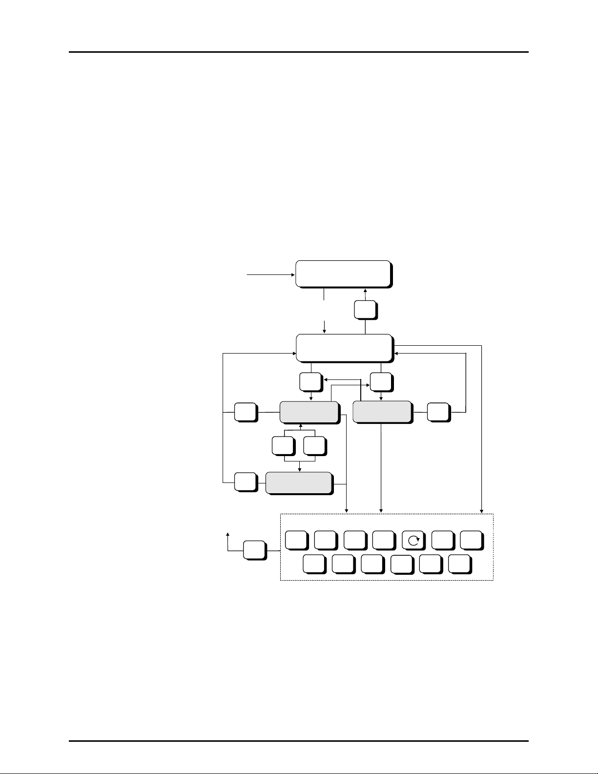
PG7601-SYS-AF™ OPERATION AND MAINTENANCE MANUAL
4.2.1.3 GENERAL FUNCTION/MENU FLOW CHART
The local operator interface with PG7601-AF system is provided by the PG Terminal
keypad and display. Normal PG7601-AF operation is organized around run screens
from which functions and menus are accessed. The run screens include:
• MAIN run screen: Displays Ready/Not Ready, defined pressure, piston
position and mass load.
• (2) SYSTEM run screens: Display piston position, rotation, temperature
and reference vacuum.
• AMBIENT run screen: Displays ambient pressure temperature, relative
humidity and local gravity.
The flow chart below outlines the operating protocol of the run screens and
associated key presses.
POWER
UP
or
RESET
INTRO SCREEN
5 SEC
≈
DELAY
ESC
RUN SCREEN
+/-
ESC
TO PREVIOUS
RUN SCREEN
ESC
SYSTEM 2
RUN SCREEN
Figure 18. RUN screen flow chart
4.2.1.4 SOUNDS
MAIN RUN SCREEN
SYSTEM
SYSTEM 1
SYSTEM
or
P-C UNIT MODE SYSTEM
RES
ENT SPECIAL SETUP
AMBIENT
AMBIENT
RUN SCREEN
OTHER FUNCTION KEYS
HEAD
ROTATE
ESCESC
AMBIENT
GEN
The PG Terminal is equipped with a variable frequency tone device to provide
audible feedback and alarms. Some sounds can be modified and all sounds can be
suppressed (see Section 4.5.4.2). Sounds are used for the following indications:
Valid key press
Invalid key press
Piston left end of stroke high or low
© 2007 DH Instruments, a Fluke Company Page 48
Brief high frequency beep.
Descending, two tone blurp.
Three rapid valid key press beeps. Piston was at low
stop or high stop and just entered spring zone (see
Section 4.1.4).
Page 63
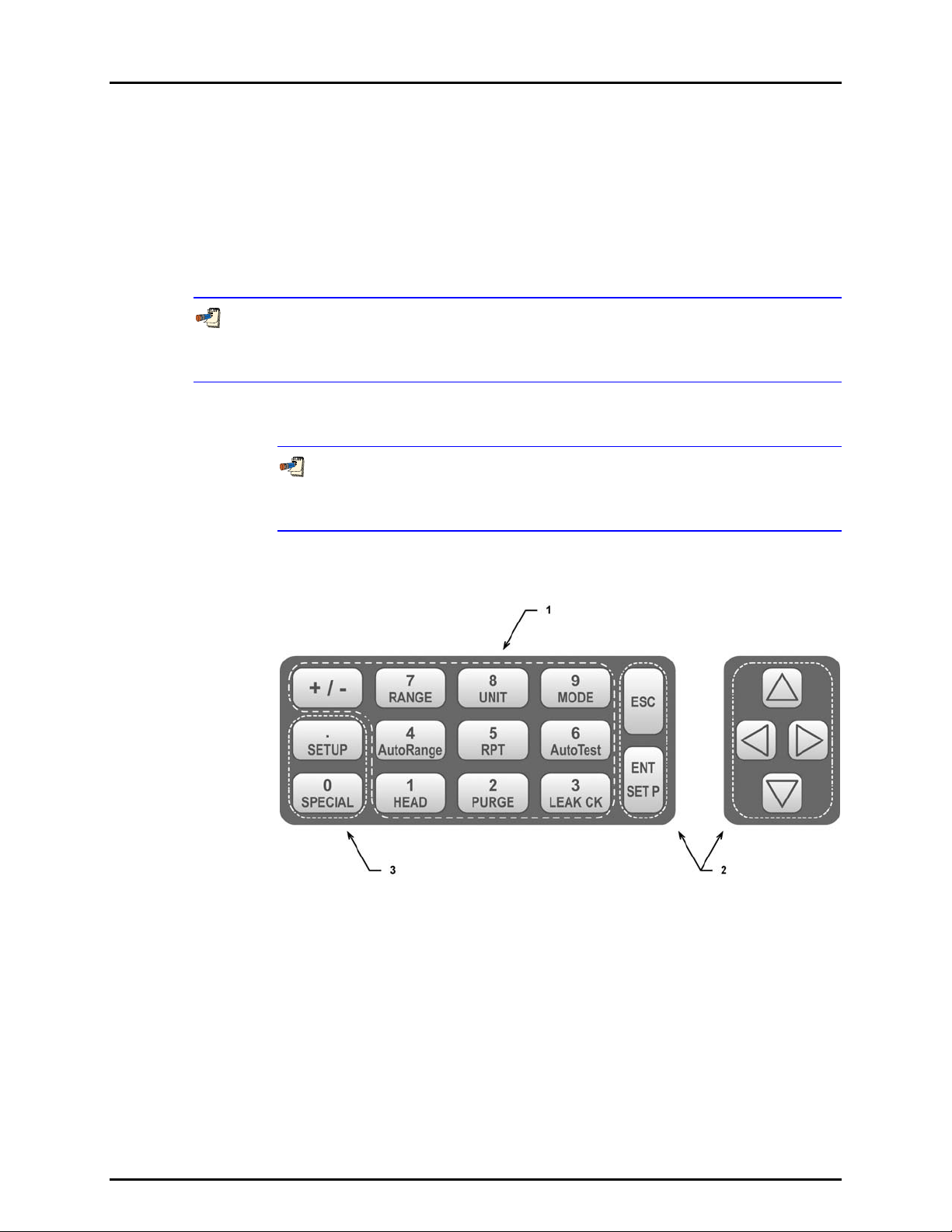
4. GENERAL OPERATION
4.2.2 PRESSURE CONTROLLER
The normal user interface to the system is the PG7601-AF Platform’s PG Terminal (see
Section 4.2.1).
PPC3-7M-AF is the pressure controlling component of the PG7601-SYS-AF system. In
normal operation, the PPC3-7M-AF pressure controller operates automatically under the
control of the PG7601-AF platform and the pressure controller front panel is not used.
exception is when the pressure controller is used manually and controlled by the operator
through its front panel direct pressure control keys.
The PPC3-7M-AF pressure controller is a component of the PG7601-SYS-AF system. It can
also act as a stand alone component. For information on use of PPC3-7M-AF outside of the
PG7601-SYS-AF system, see the PPC3 Operation and Maintenance Manual.
4.2.2.1 KEYPAD LAYOUT AND PROTOCOL
In typical PG7601-SYS-AF system operation, the PPC3-7M-AF pressure
controller keypad is not used. Occasionally, when using manual pressure control (see
Section 4.1.2), [ENT/SET P] may be used to set a pressure.
The
The PPC3 has a function/data keypad for local operator access to direct
functions, function menus and for data entry.
1. The Function/Data keys allow very
commonly used functions to be accessed
directly by a single keystroke when pressed
from the MAIN run screen (see PPC3
Operation and Maintenance Manual). The
name of the function is on the bottom half of
the key. These keys enter numerical values
when editing.
2. The Editing and Execution keys are for
starting and suspending command execution,
cursor control in menus and editing entries.
3. The Menu/Data keys provide access to
function menus when pressed from the MAIN
run screen. The menu name is on the bottom
half of the key. The SETUP menu is for more
frequently used functions. The SPECIAL
menu is for functions that are not generally
used as a part of day to day operation. These
keys enter numerical values when editing.
Figure 19. Pressure controller keypad layout
Pressing [ENT/SET P] generally causes execution or forward movement in the
menu tree. Pressing [ENT/SET P] from the MAIN run screen allows an
automated pressure control command to be given.
Page 49 © 2007 DH Instruments, a Fluke Company
Page 64
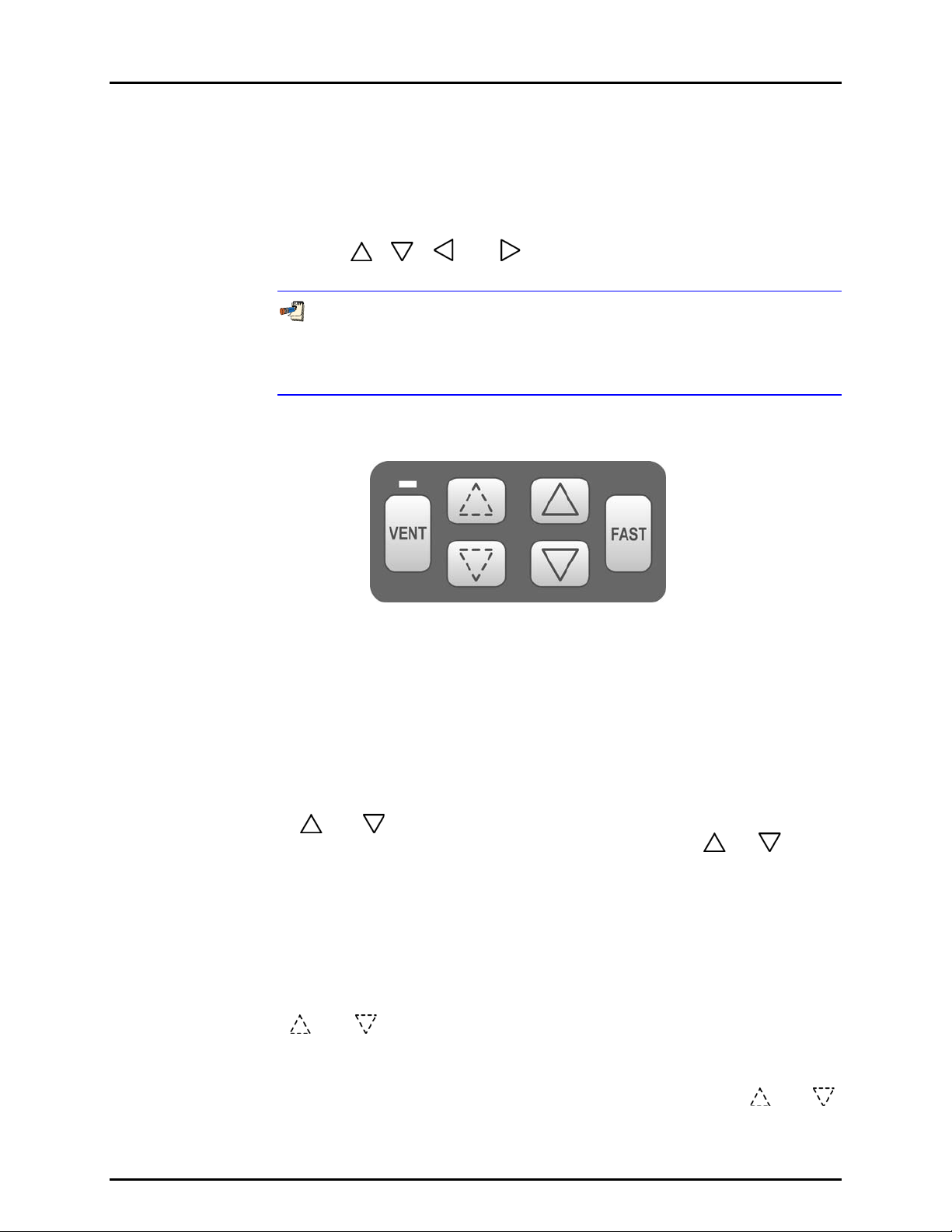
PG7601-SYS-AF™ OPERATION AND MAINTENANCE MANUAL
Pressing [ESC] moves back in the menu tree and/or causes execution to cease
or suspend. Pressing [ESC] repeatedly eventually returns to the MAIN run screen
and, from there, allows momentary viewing of the PPC3 introduction screen.
Pressing [+/-] changes a numerical sign when editing. It also toggles through
multiple screens when available and is a shortcut to a momentary display of the
active RANGE from the MAIN run screen.
Pressing [
], [ ], [ ] and [ ] allows reverse, forward and up, down cursor
movement when editing data entry or moving in menus.
The PPC3-7M-AF pressure controller is a component of the PG7601-SYS-AF
system. It can also act as a stand alone component. For information on use of
PPC3-7M-AF outside of the PG7601-SYS-AF system, see the PPC3 Operation and
Maintenance Manual provided on the PG7601-SYS-AF Support Disc.
4.2.2.2 DIRECT PRESSURE CONTROL KEYS
Figure 20. Pressure controller direct pressure control keys
The [ENT/SET P] key of the PPC3-7M-AF main keypad can be used to set a target pressure
that PPC3-7M-AF will automatically set and maintain. Once the target pressure has been
reached, control at the target pressure value continues until [ESC] or another function key is
pressed.
The PPC3-7M-AF direct pressure control keys (Figure 20) provide direct manual control of
pressure increase, decrease, jog and vent. They can be used to adjust pressure manually
directly under operator control rather
than under control of the PG7601-AF AutoGen
automated pressure control function (see Section 4.3.9).
Pressing the [
decrease at the slow slew rate. Holding [FAST] pressed while pressing [
] or [ ] direct pressure control keys causes pressure to increase or
] or [ ] causes
the pressure increase or decrease speed to change from slow to fast.
Pressing [VENT] causes PPC3-7M-AF to control pressure to near atmospheric pressure and
then open its internal vent valve. On-going execution of the vent function is indicated by
lighting a RED LED just above the [VENT] key. Completion of the vent process is indicated
by the PPC3-7M-AF’s Ready/Not Ready indicator light becoming GREEN with the vent RED
LED still lighted. The vent valve remains open until [VENT] is pressed again, another direct
pressure control key is pressed, or an automated pressure control command is given from
the PPC3-7M-AF front panel or by the PG7601-AF AutoGen function.
Pressing the [
] and [ ] direct pressure control keys causes the pressure to jog or step by a
fixed amount. During active pressure control, they cause the target pressure to be changed by
the fixed amount. One press causes one step. The approximate value of the step is set
automatically depending on the current active PPC3 range. The value can be adjusted using
[SETUP], <3jog> or pressing both the up and down jog keys simultaneously. The [
] and [ ]
keys are not normally used when PPC3-7M-AF is part of a PG7601-SYS-AF system.
© 2007 DH Instruments, a Fluke Company Page 50
Page 65

4. GENERAL OPERATION
Before using the PPC3-7M-AF pressure controller direct pressure control keys, be sure that
the PG7601-AF platform AutoGen function is OFF or not active. The AutoGen function can be
made inactive by pressing [ESCAPE] on the PG Terminal.
When using PPC3-7M-AF for direct pressure control, do not make any other changes or
adjustments. Do not change units of measure ([UNIT]) or measurement mode ([MODE]).
4.2.2.3 MAIN RUN SCREEN
In typical PG7601-SYS-AF system operation, the PPC3-7M-AF pressure
controller keypad is not used. Occasionally, when using manual pressure control
(see Section 4.1.2), [ENT/SET P] may be used to set a pressure.
The PPC3-7M-AF pressure controller MAIN run screen is its home display that is
reached on power-up and from which other functions and menus are accessed.
It is the very top level of all menu structures.
The MAIN run screen is where the operator works with PPC3-7M-AF pressure
controller to set and read pressures. It provides complete information on the
system’s current configuration and operating status.
Figure 21 and its legend table summarize the PPC3 MAIN run screen fields and
their functions.
PPC3 has a screen saver function which causes the display to dim if no key is
pressed for 10 minutes. Pressing a key restores full power to the display. The screen
saver time can be changed or screen saving can be completely suppressed (use
[SPECIAL], <5prefs>, <1ScrSav> from the PPC3-7M-AF front panel).
PRESSURE1UNITm hzRRH
TPRESSURE2 CC NN/NN
DISPLAY FIELD NAME PURPOSE CONTENTS
1. PRESSURE1 Measured
2. UNIT Unit of
3. m Measurement
pressure
measure
mode
Displays pressure
measured by PPC3-7MAF internal utility sensor
Identifies pressure unit of
measure in which
PRESSURE1 and
PRESSURE2 are
displayed
Identifies measurement
mode of displayed
pressure
Numerical pressure value
and sign
Pressure unit of measure
abbreviation
<a>: absolute
<g>: gauge
Page 51 © 2007 DH Instruments, a Fluke Company
Page 66

PG7601-SYS-AF™ OPERATION AND MAINTENANCE MANUAL
DISPLAY FIELD NAME PURPOSE CONTENTS
4. h Head
5. z AutoZero
6. RRH Active RPT
7. NN/NN
(not used in normal
PG7601-SYS-AF
operation)
8. CC Pressure
9. TPRESSURE2 Pressure
pressure
indicator
indicator
position
indicator
Sequence
progress
indicator
control
indicator
information
indicatior
Indicates whether a fluid
head correction is applied
to PRESSURE1
Indicates whether the
AutoZero function is ON
or OFF
Indicates the position of the
active utility sensor.
Normally <IuH> when used
in PG7601-SYS-AF
Indicates progress of an
ATest sequence, during
test execution
Indicates type of pressure
control, whether control is
currently active and
whether custom contr ol
limits are in use. Normally
<D> when used in PG7601SYS-AF
Pressure indication
depending on current
PPC3 function. Leading
character identifies the
value.
<h>: the fluid head
is not zero
<blank>: fluid head is
zero
<z>: AutoZ is ON
<blank>: AutoZ is OFF
<IH>: Internal Hi
<IuH>: Internal Hi
(utility sensor)
<X1H>: External 1 Hi
<X1L>: External 1 Lo
<X2H>: External 2 Hi
<X2L>: External 2 Lo
<NN/NN>: Number of this
point over total number of
points in the sequence
<D>: Control mode is
dynamic
<S>: Control mode is
static
<C> is appended to the <D>
or <S> if control limits are
custom
Control character(s)
flash if PPC3 is actively
controlling
<R>: Pressure rate of
change in current
pressure unit/second
<T>: Pressure control
target
<D>: Deviation from the
pressure control
target
Figure 21. Pressure controller MAIN run screen display fields
4.2.2.4 SOUNDS
PPC3 is equipped with a variable frequency tone device to provide audible
feedback and alarms. The beeper is used for the following indications.
Valid key press Brief beep. Choice between three
Invalid key press Descending two tone “blurp”.
Leak check completed Three two second beeps.
Upper or lower limit exceeded Intermittent one second beeps.
Pmax! (overpressure limit) exceeded Eight second high frequency beep.
© 2007 DH Instruments, a Fluke Company Page 52
frequencies or NO sound is available.
Page 67

4. GENERAL OPERATION
4.3 DIRECT FUNCTION KEYS
4.3.1 DIRECT FUNCTION KEYS SUMMARY
Local operator interface with the PG7601-SYS-AF system is provided by the PG Terminal
keypad and display. To minimize the use of multi-layered menu structures, the keypad’s
numerical keys also provide direct access to the most commonly used functions. The
function accessed is labeled on the bottom half of the each key. Direct function keys are
active whenever PG7601-AF is in a run screen (MAIN, SYSTEM or AMBIENT). Table 10
summarizes the operation of the direct function keys. Section 4.2.1.3 provides a flow chart of
PG Terminal general operation. See corresponding manual Sections to 4.3.2 to 4.3.13.
It may be useful to keep a copy of Table 10 near the PG7601-AF, especially when first
becoming acquainted with its operation.
Table 10. Summary of PG7601-AF PG Terminal direct function key operations
DIRECT FUNCTION KEYS ARE ACTIVE FROM ANY RUN SCREEN
See corresponding manual sections for full detail.
Menu of less frequently used internal
functions and settings including resets,
user preferences, internal calibration
and remote interface setup.
Edit and select files that determine the
sources of the values for the variables
PG7601-AF uses in calculations of
reference pressures.
Select pressure to mass or mass to
pressure operation.
(main, ambient, system).
Activate motorized piston rotation
acceleration and deceleration manually.
From a run screen: Access mass or
pressure setting command. From other
screens: select menu choice, enter
value, confirm selection.
Turn automatic activation of motorized
rotation ON/OFF.
Set the resolution of PG7601-AF mass
loading commands (0.01 g to 0.1 kg).
Access SYSTEM run screens (2) which
display current measurements of piston
behavior, piston-cylinder temperature
and reference vacuum if present.
Toggles between the two screens.
Access AMBIENT run screen which
displays current values of barometric
pressure, ambient temperature, ambient
humidity and local gravity as specified in
the active SETUP file.
Adjust height of DUT fluid head
correction. Set to zero to defeat head
correction.
View available piston-cylinder modules
(range) and select active one.
Set unit of measure in which pressure is
defined. Choice of units available from
this key can be customized.
Turn automated pressure
generation/control ON/OFF, adjust
control parameters, set upper limit for
automated pressure control.
Set pressure measurement mode
(gauge, absolute).
4.3.2 [P-C], VIEW AND SELECT PISTON-CYLINDER MODULES
PURPOSE
To view and/or change the active piston-cylinder module. Changing the piston-cylinder
Page 53 © 2007 DH Instruments, a Fluke Company
module is equivalent to changing the range.
Page 68

PG7601-SYS-AF™ OPERATION AND MAINTENANCE MANUAL
[P-C] is for selecting the active piston-cylinder module only. Piston-cylinder modules can be
added and deleted and their characteristics can be edited by pressing [SPECIAL], <1PC/MS> (see
Section 4.5.1).
The active mass set and mass loading bell are selected by pressing [SPECIAL], <1PC/MS>
(see Section 4.5.1).
PRINCIPLE
To make valid pressure and mass load calculations, PG7601-AF must know the exact
characteristics of the piston-cylinder module that is currently in use. See Section 9.2.1 for
detailed information on PG7601-AF pressure and mass calculations.
Most PG7601-AFs are used with more than one piston-cylinder module.
Detailed characteristics on up to 18 piston-cylinder modules can be stored in digital
identification records (digital IDs). Digital IDs can be added, viewed, edited and deleted
locally using [SPECIAL], <1pc/ms> (see Section 4.5.1) or remotely using CalTool for
o
PG7000 s
ftware.
The P-C function provides rapid access, from any run screen, to viewing the piston-cylinder
modules available and selecting one to be active.
OPERATION
Pres [P-C] to activate the piston-cylinder module viewing and selecting function. Press [P-C]
again or [+/-] while in the P-C function to step through displays of available piston-cylinder
modules.
When [P-C] is first pressed, a summary of the characteristics of the active piston-cylinder
module is displayed, for example:
1. Nominal pressure to mass conversion coefficient of the pistoncylinder module that is currently selected (active). This value is
calculated from the effective area of the piston-cylinder and is
always in kPa/kg.
2. Serial number of the active piston-cylinder module.
3. Current pressure unit of measure.
4. Nominal pressure in current pressure units resulting from
loading all the mass of the active mass set.
5. Nominal pressure in current pressure units resulting from
loading the piston and mass bell only.
Active 10 kPa/kg 247
1.02 to 51.8 psi
Pressing [P-C] again or [+/-] causes the screen to step through the other available pistoncylinder modules in the sequence that they were added.
1. Nominal pressure to mass conversion coefficient of the pistoncylinder module. This value is calculated from the effective
area of the piston-cylinder and is always in kPa/kg.
2. Serial number of the piston-cylinder module.
3. Current pressure unit of measure.
4. Nominal maximum pressure using the piston-cylinder module.
Pressure, in current pressure units, resulting from loading all
the mass of the active mass set.
5. Nominal minimum pressure using the piston-cylinder module.
Pressure, in current pressure units, resulting from loading the
piston and mass bell only.
Pressing [ENTER] while in the P-C function causes PG7601-AF to select the currently
displayed piston-cylinder module as the active piston-cylinder module.
© 2007 DH Instruments, a Fluke Company Page 54
Select 200kPa/kg 382
14 to 1000 psi
Page 69

4. GENERAL OPERATION
Pressing [ESCAPE] while in the P-C function returns to the MAIN run screen without
changing piston-cylinder modules.
The pressure unit of measure in which the range offered by the piston-cylinder module using
the active mass set is displayed can be changed by pressing [UNIT] (see Section 4.3.3).
When the current pressure unit of measure is an altitude unit, piston-cylinder module range
is expressed in kPa if the altitude unit is meters (m) or psi if the altitude unit is feet (ft).
4.3.3 [UNIT], SELECT PRESSURE UNIT OF MEASURE
PURPOSE
To specify the unit of measure in which pressure defined by the PG7601-AF and other
pressure values are expressed.
PRINCIPLE
PG7601-AF supports a wide variety of pressure units of measure. Internally, PG7601-AF
always operates in Pascal [Pa] (the SI unit of pressure). Values of pressure are represented
in other units by the application of conversion factors to convert from Pascal.
See Section 9.1.1 for unit of measure conversions.
The pressure unit of measure selection (e.g., psi, kPa, etc.) is separate from the pressure
measurement mode selection (gauge, absolute). See Section 4.3.4 for information on
changing the measurement mode.
OPERATION
To change
[UNIT] function key from any run screen. The
display is:
the pressure unit of measure, press the
1psi 2kPa 3inHg
4mmHg 5inWa 6ft
The cursor is on the number corresponding to the active unit. To change the unit, select the
desired unit. The display returns to the previous run screen with the selected unit active.
If the pressure unit selected is inWa, the reference
Select inWa ref temp
temperature for water density must be specified. When
inWa is selected as the unit, the next display is:
4°C 20°C 60°F
Select the desired reference temperature for water density using [←] or [→] to move the
cursor. Pressing [ENTER] returns to the MAIN run screen with inWa based on water density at
the selected reference temperature as the active pressure unit. The current inWa reference
temperature can be viewed by observing the position of the cursor in the reference temperature
screen.
See Section 9.1 for tables of the pressure unit of measure conversion factors used by
PG7601-AF.
Page 55 © 2007 DH Instruments, a Fluke Company
Page 70

PG7601-SYS-AF™ OPERATION AND MAINTENANCE MANUAL
The UNIT function provides rapid access to a choice of up to six units. The choice of units
can be customized from a wider selection by the user (see Section 4.5.2). The default units are:
1psi 2kPa 3inHg 4mmHgr 5inWa 6ft
To restore the default UNIT function settings, use the Unit Reset (see Section 4.5.9.2).
Certain internal and/or metrological functions (e.g., vacuum reference pressure) are always
represented in Pascal [Pa], regardless of the active pressure unit of measure.
When the current pressure unit of measure is an altitude unit, atmospheric pressure in the
AMBIENT run screen is expressed in kPa if the altitude unit is meters (m) or psi if the altitude
unit is feet (ft).
4.3.4 [MODE], SELECT PRESSURE MEASUREMENT MODE
PURPOSE
To specify the measurement mode (gauge, absolute) in which PG7601-AF defines reference
pressures.
Pressure measurement mode and unit of measure is not the same thing. See Section 4.3.3
for information on the pressure unit of measure.
PRINCIPLE
Pressure defined relative to absolute zero or vacuum is generally referred to as absolute
pressure.
Pressure defined relative to atmospheric pressure is generally referred to as gauge pressure.
PG7601-AF can define absolute and gauge pressure. These are referred to as
measurement modes.
The specific PG7601-AF measurement modes are as follows:
• gauge: Defines gauge pressure by leaving the PG7601-AF mass load open to
atmosphere. It does not allow negative gauge pressures. The minimum gauge
pressure is the pressure resulting from loading the combined mass of the piston and the
bell on piston-cylinder effective area.
• absolute by vacuum (absolute by vac): Defines absolute pressure by measuring
relative to an evacuated bell jar. This mode is time consuming as the vacuum under the
bell jar must be made and broken to adjust the mass load for each pressure to be set.
This mode is required for setting absolute pressures under atmospheric pressure.
• absolute by adding atmospheric pressure (absolute by ATM): Defines absolute
pressure by defining a pressure in the same manner as in gauge mode and adding the
value of atmospheric pressure measured by a barometer. The barometer can be
PG7601-AF’s on-board sensor or a remote RS232 barometer (not included in standard
PG7601-SYS-AF system). The uncertainty on the value of atmospheric pressure
measured by the barometer must be considered but this value can become relatively
small as pressure goes up. For example, if using a ± 0.01 % barometer, the added uncertainty
at 1 MPa (150 psi) is 10 ppm.
This mode is more convenient than absolute by vacuum since no vacuum reference
needs to be established. However, it does not allow absolute pressures under
© 2007 DH Instruments, a Fluke Company Page 56
Page 71

4. GENERAL OPERATION
atmosphere and the minimum absolute pressure is atmospheric pressure plus the pressure
resu lting from loading the combined mass of the piston and the bell on the piston-cylinder
effective area.
OPERATION
To change the pressure measurement mode, press [MODE] from any run screen.
Measurement mode:
The display is:
1g 2avac 3aatm
The cursor is on the number corresponding to the current measurement mode.
Selecting <1g> accesses gauge mode.
Selecting <2avac> accesses absolute by vacuum mode.
Selecting <3aatm> accesses absolute by ATM mode.
Making a measurement mode selection returns to the previous run screen with the selected
mode active.
4.3.5 [SYSTEM], VIEW SYSTEM CONDITIONS MEASUREMENT SCREENS
PURPOSE
To access the two SYSTEM run screens which display current values of PG7601-AF piston
behavior, piston-cylinder temperature and vacuum reference measurements.
OPERATION
To access the SYSTEM run screens, press [SYSTEM] from any other run screen. There are
two SYSTEM run screens. Pressing [SYSTEM] or [±] when in a SYSTEM screen toggles
between the first and second SYSTEM screens.
See Sections 4.3.5.1 and 4.3.5.2 for detailed information on
second SYSTEM run screens.
contents of the first and
the
The SYSTEM screens are run screens. This means that other functions can be accessed
from the SYSTEM screens and the active SYSTEM screen will be returned to when leaving
functions. The MAIN screen and AMBIENT screen are also run screens (see Section 4.2.1.3).
4.3.5.1 FIRST SYSTEM RUN SCREEN
OPERATION
The first SYSTEM run screen provides real time display of piston rotation rate,
decay in piston rotation rate, piston position and piston fall rate.
To access the first SYSTEM run screen, press [SYSTEM] from any other
run screen.
Page 57 © 2007 DH Instruments, a Fluke Company
Page 72

PG7601-SYS-AF™ OPERATION AND MAINTENANCE MANUAL
The first SYSTEM run screen displays:
1. <nnn rpm>: Numerical value of current
piston rate of rotation. The unit of measure is
rotations per minute [rpm] and cannot be
changed. Flashes when Not Ready and
piston is floating (see Section 4.1.3.2).
Indicates < ----
unavailable or out of range. Message
indicating piston rotation is being accelerated
or decelerated is displayed to the right when
motorized rotation is engaged.
2. <±nn/min>: Numerical value of current decay
in piston rotation rate (deceleration). The unit
of measure is rotations per minute [rpm/min]
and cannot be changed. < ---- > when
information is unavailable or out of range.
Message indicating piston rotation is being
accelerated or decelerated is displayed here
when motorized rotation is engaged.
3. <±n.nn/min>: Sign and numerical value of current piston vertical rate of displacement. A
negative value indicates piston falling. A positive value indicates piston rising. The unit of measure
is millimeters per minute [mm/min] and cannot be changed. Indicates < ---- > when
information is unavailable or out of range.
4. <±n.nn mm>: Sign and numerical value of current position of the piston within the piston
stroke (see Section 4.1.4) relative to the mid-stroke position. The unit of
millimeters [mm] and cannot be changed. Indicates <HSTOP> when the piston is at the high
stop (all the way up) and <LSTOP> when the piston is at the low stop
(all the way down). Flashes when Not Ready and piston is floating (see Section 4.1.3.1). Indicates
< ---- > when information is unavailable or out of range.
hen information is
> w
nnn rpm ±nn/min
±n.nn mm ±n.nn/min
measure
is
Pressing [ESCAPE] in the first SYSTEM run screen returns operation to the MAIN
run screen. Pressing [SYSTEM] or [±] toggles between the first and second run
screen. All function keys are active from the first SYSTEM run screen and
operation returns to that screen when leaving functions the were accessed from it.
The measurement systems for piston behavior indications rely on movement of
the mass loading bell. Piston behavior indications (piston position, piston rotation
rate) are not valid when the mass bell is not loaded on the piston.
See Section 4.1.4 for information on the piston stroke and measurement zone.
4.3.5.2 SECOND SYSTEM RUN SCREEN
OPERATION
The second SYSTEM run screen displays the values of piston-cylinder
temperature and temperature rate of change. Vacuum and vacuum rate of
change are also displayed. If internal or external measurement is specified for
the vacuum values in SETUP (see Section 4.4), the second SYSTEM run screen
provides a real time display of the values measured.
To access
SYSTEM run screen. To access the first SYSTEM run screen, press [SYSTEM]
from any run screen.
the second SYSTEM run screen, press [SYSTEM] or [±] from the first
© 2007 DH Instruments, a Fluke Company Page 58
Page 73

4. GENERAL OPERATION
The second SYSTEM run screen displays:
1. <n.nn°C>: Current piston-cylinder
temperature. Source of value can be internal
measurement, default or user depending on
current SETUP selection (see Section 4.4).
The unit of measure is degrees
[±°C] and cannot be changed. Indicates
> when information is unavailable or out of
range.
2. <+n.nn/min>: Sign and numerical value of
current rate of change of temperature. A
negative value indicates temperature
decreasing. A positive value indicates
temperature increasing. The unit of
measure is degrees Centigrade per minute
[°C/min] and cannot be changed. Indicates < --
-- > when information is unavailable or out of
range. Indicates < ---- > when “user” or
“default” is the current SETUP selection for
piston-cylinder temperature source (see
Section 4.4).
3. <+nnn.n/min>: Sign and numerical value of current rate of change of the vacuum reference
pressure. A negative value indicates pressure decreasing. A positive value indicates pressure
increasing. The unit of measure is Pascal per minute [Pa/min] and cannot be changed.
Indicates < ---- > when information is unavailable or out of range. <Blank> if the PG7601-AF
model is not PG7601-AF or if user or default is the current SETUP selection for reference
vacuum (see Section 4.4).
4. <nnn.n Pa>: Current vacuum reference value.
measurement, default or user depending on current SETUP selection. Flashes when Not
Ready and piston is floating (see Section 4.1.3.3). The unit of measure is Pascal [Pa] and
cannot be changed. Indicates < >20 Pa > if current SETUP selection is internal or external and
current measurement is out of range or greater than 20 Pascal.
is not PG7601.
Centigrade
< ----
n.nn°C ±n.nn/min
nnn.n Pa ±nnn.n/min
Can be internal measurement, external
<Blank> if PG7601-AF model
Pressing [ESCAPE] in the second SYSTEM run screen returns operation to the
MAIN run screen. Pressing [SYSTEM] or [±] toggles between the first and
second SYSTEM run screen. All function keys are active from the second
SYSTEM run screen and operation returns to that screen when leaving functions
that were accessed from it.
The current selection in SETUP determines the source of the values used by
PG7601-AF for piston-cylinder temperature and vacuum reference values (see
Section 4.4). If the SETUP setting is user or default, the SYSTEM screen displays
the user or default value, not PG7601-AF’s on-board measurement(s).
4.3.6 [AMBIENT], VIEW AMBIENT CONDITIONS MEASUREMENTS SCREEN
PURPOSE
Access the AMBIENT run screen which displays the current ambient condition values being
used by PG7601-AF for calculations of reference pressure.
PRINCIPLE
PG7601-AF uses ambient condition values to calculate the reference pressures that it
defines (see 9.2.1). The source of the ambient condition values is specified in the current
SETUP file (see Section 4.4). The AMBIENT run screen displays the current ambient
condition values. If the SETUP selection for t
then the AMBIENT run screen provides a real time display of the measurement by
PG7601-AF’s on-board sensor for that variable.
he ambient condition is internal measurement,
Page 59 © 2007 DH Instruments, a Fluke Company
Page 74
PG7601-SYS-AF™ OPERATION AND MAINTENANCE MANUAL
OPERATION
To access the AMBIENT run screen, press [AMBIENT] from any other run screen (MAIN
or SYSTEM).
The AMBIENT screen is a run screen. This means that other functions can be accessed from
the AMBIENT screen and the active AMBIENT screen will be returned to when leaving functions. The
MAIN screen and SYSTEM screens are also run screens (see Sections 4.2.1.2 and 4.3.5)
The AMBIENT run screen displays:
1. <nnnnnnn uuuu>: Current numerical value and pressure
unit of atmospheric pressure. Source of value can be internal
measurement, remote barometer, default or user depending
on current SETUP selection (see Section 4.4). The unit of
measure is determined by
Section 4.3.3). ATM head is applied to internal or external
barometer reading to correct atmospheric pressure
PG7601-AF reference level (see Section 9.2.2.1). Indicates <
---- > when information is unavailable or
Indicates <TIMEOUT> if the current SETUP selection is a
remote barometer and PG7601-AF communication with the
barometer times out.
2. <n.nn°C>: Current ambient temperature. Source of value can be internal measurement, default or user
depending on current SETUP selection (see Section 4.4). The unit of measure is degrees Centigrade [ºC] and
cannot be changed. Indicates < ---- > when information is unavailable or out of range.
3. <n.nnnnnnm/s2>: Value of local acceleration due to gravity
selection (see Section 4.4). The unit of measure is meters per second squared [m/s2] and cannot be changed.
4. <nn%RH>:
current SETUP selection (see Section 4.4). The unit of measure is percent relative humidity [%RH] and
cannot be changed. Indicates < -- > if current SETUP selection is internal and current
unavailable or out of range.
Current ambient relative humidity. Can be internal measurement, default or user depending on
the UNIT function setting (see
out of range.
nnnnnnn uuuu nn.n°C
the
to
. Can be default or user depending on current SETUP
nn%RH n.nnnnnn/s2
measurement
is
Pressing [ESCAPE] in the AMBIENT run screen returns operation to the MAIN run screen.
All function keys are active from the AMBIENT run screen and operation returns to that
screen when leaving functions that were accessed from it.
The current selection in SETUP determines the source of the values used by PG7601-AF for
atmospheric pressure, ambient temperature and relative humidity. If the SETUP setting for these
values is user or default, the AMBIENT screen displays the user or default value, not PG7601-AF’s
on-board measurement(s).
To change the ambient pressure unit of measure, see Section 4.3.3. When the current
pressure unit of measure is an altitude unit, atmospheric pressure in the AMBIENT run screen is
expressed in kPa if the altitude unit is meters (m) or psi if the altitude unit is feet (ft).
4.3.7 [HEAD], SET FLUID HEAD CORRECTION HEIGHT
PURPOSE
To cause a pressure value, representing the fluid head resulting from a difference in height,
to be added to the pressure defined by PG7601-AF at its reference level. To set the height of
the DUT head.
PRINCIPLE
The pressure defined by the PG7601-AF’s floating piston is the pressure at the bottom of the
piston. This is referred to as the PG7601-AF reference level. The height of the bottom of the
piston with the piston in mid-stroke position is marked reference level on the PG7601-AF
piston-cylinder module mounting post. Frequently, when performing a calibration or test, the
© 2007 DH Instruments, a Fluke Company Page 60
Page 75
4. GENERAL OPERATION
device or system under test is at a different height than the PG7601-AF reference level. This
difference in height (referred to as DUT head) can cause a significant difference between the
pressure defined by the PG7601-AF at its reference level and the pressure actually applied to
the device under test located at a different height. In this case, it is useful to make a head
correction to the pressure defined by the PG7601-AF at its reference level in order to
accurately predict the pressure actually applied at a different height. The HEAD function
allows this head correction to be applied automatically based on operator entry of the height
difference. The fluid used and the HEAD function unit of measure are set using [SPECIAL],
<3head> (see Section 4.5.3).
PG7601-AF can accurately determine head pressures for gases (nitrogen, helium and air) and
i
quids (Di-2 ethylhexyl Sebacate oil, water and a user defined liquid) as the pressurized
l
medium. A liquid head might be useful if the PG7601-AF is used with a gas/liquid interface.
When gas is the test fluid, use of the HEAD function is most important at low
absolute pressures. In this case, specifying the head height within ± 0.2 in. (5 mm) is adequate
to ensure that, even in the worst case, the uncertainty on the head correction will be insignificant
relative to the tolerance on the PG7601-AF measurement. Use of the HEAD function to ensure in
tolerance measurements is particularly critical when a liquid is the test fluid, due to the high
density of liquids. To determine when and how precisely a head correction for liquids must be
made, 0.03 psi/inch (90 Pa/cm) may be used as an estimation of the liquid head value.
Regardless of the DUT head function’s setting, corrections are automatically applied to the
calculated reference pressure to compensate for the deviation between the current piston
position and the mid-stroke position (see Section 4.5.3).
The pistons of the 10 kPa/kg and 50 kPa/kg piston-cylinder modules are hollow. Therefore,
the natural reference level is not at the bottom of the piston. So that, in practice, the actual
reference level is the same for all piston-cylinder modules, a reference level offset is applied when a
hollow piston is used. The reference level offset is included in the piston-cylinder digital ID (see
Section 4.5.1.1) and corrects the reference level back to the reference point marked on the
mounting post.
OPERATION
To access the HEAD function, press [HEAD]. The display is:
Edit DUT head height
1. Test fluid currently specified for the head correction.
2. Entry field for head height (1 to 999 cm or in.).
95 cm N2
Entering a value of zero turns the HEAD function OFF. Entering a value other than zero
turns the HEAD function ON using the height entered. Pressing [ESCAPE] returns to the
MAIN run screen with NO change to the current head setting. A separate function in
[SPECIAL] is used to change the head fluid or height unit (see Section 4.5.3).
Page 61 © 2007 DH Instruments, a Fluke Company
Page 76

PG7601-SYS-AF™ OPERATION AND MAINTENANCE MANUAL
Reference
Line
(+)
REFERENCE
LEVEL
(-)
The reference height of PG7601-AF pressure definition is the bottom of the piston in midstroke float position. This position is marked on the piston-cylinder module mounting post.
The DUT head height should be entered as a positive value if the device or system under test is
higher than the PG7601-AF reference level and negative if it is lower.
To change units of DUT head height between inches and centimeters and to change the test
fluid, use [SPECIAL], <3Head> (see Section 4.5.3).
When the HEAD function is ON (DUT head value different from 0), the application of a head
correction is indicated by <h> in the right side of the top line of the MAIN run screen (see
<h>
Section 4.2.1.2). When the HEAD function is OFF, the
is NOT shown. PG7601-AF also has a
separate head correction to compensate for the deviation between the current piston position
and mid-stroke (see Section 4.5.3). This PISTON head can be turned ON and OFF.
4.3.8 [ROTATE], MANAGE MOTORIZED PISTON ROTATION
PURPOSE
To turn automatic control of motorized piston rotation (acceleration and deceleration) ON
and OFF.
See Section 4.3.13 for information on manual control of motorized piston rotation.
PRINCIPLE
The motorized piston rotation system is used to start or increase piston rotation rate when the
piston is floating. It is also used to stop piston rotation when necessary, for example before
manipulating mass to set a new pressure moving the piston to the end of its stroke. The
system operates by engaging a motor driven belt around the bottom of the mass loading bell
to accelerate or brake the rotation rate of the mass bell and piston it is loaded on. The
motorized rotation system can engage with the piston at any position in its stroke and at any
rotation speed with minimal impact on piston position and the defined pressure. When the
motorized rotation system disengages, the piston is completely free.
With automatic motorized rotation ON, the motorized rotation system engages and
disengages automatically as needed when the piston is floating to maintain the piston
rotation rate above the minimum rate Ready limit (see Section 4.1.3.2). Th e rot atio n rat e is
the
measured by PG7601-AF on board sensors and the rotation rate limits are set in
digital
ID of the active piston cylinder (see Section 4.5.1.1). Whenever the piston is floating, the
motorized rotation system will attempt to maintain the piston rotation rate within
limits (except under the cutoff mass load of 3 kg where the low rotation limit becomes 5 rpm).
the Ready
The piston rotation Ready/Not Ready indication character indicates Not Ready to alert the
© 2007 DH Instruments, a Fluke Company Page 62
Page 77
4. GENERAL OPERATION
operator when the motorized rotation system is about to engage. The rotation system will not
engage when the current mass load is less than the mass of the piston + mass loading bell.
The motorized rotation system is also used to decelerate and stop rotation when starting a
new pressure point. If the piston is floating and rotating when [ENTER/SET P] is pressed,
the motorized rotation system engages at a speed near the rotation rate of the piston and
then brakes it to a stop. Piston rotation is stopped to avoid loading and unloading masses on
the rotating piston and to avoid stopping rotation by friction between the piston and the piston
end of stroke stops.
With automatic motorized rotation OFF, the motorized rotation system engages only when
actuated by the operator. Pressing [
] accelerate rotation or [ ] followed by [←] stops
rotation (see Section 4.3.13). Rotation should always be stopped before the piston is moved
up or down against the end of stroke stop.
Automatic motorized rotation is generally left
ON for normal operation. It is turned OFF in
situations where rotation system actuation independent of operator initiative is undesired
(e.g. when performing a crossfloat intercomparison with another piston gauge).
OPERATION
Piston rotation should always be stopped by the motorized rotation system or manually
before the pressure is changed. Piston rotation should not be stopped by friction of the rotating
piston against the upper or lower end of stroke stop.
To access the AutoRotate functions, press
[ROTATE]. The display is:
AutoRotate OFF
1on 2pre-decel
<AutoRotate ON> or <AutoRotate OFF> indicates the current state of AutoRotate. Use
<1on> or <1off> to change the state.
When automated rotation is OFF, the PG7601-AF motorized rotation system will only engage
if the operator presses [
] or [ ] followed by [←] (see Section 4.3.13).
When automated rotation is ON, the automated rotation system engages automatically.
When the piston is floating, it engages as needed to maintain the piston rotation rate within
the rotation rate Ready limits (see Section 4.1.3.2). When [ENTER/SET P] is pressed, it
engages to stop rotation before masses are loaded and/or the
function can be turned ON and OFF, see Section 4.3.8.1). Manual control using [
] followed by [←] is also still active.
[
pressure is adjusted (this
] and
Automatic motorized piston rotation is dependent on PG7601-AF’s measurements of
piston position and rotation rate. These measurements are only available when the mass loading
bell is installed on the piston. Automatic piston rotation is suspended when the current PG7601AF mass load does not include the mass loading bell.
Proper operation of the rotation system is dependent on PG7601-AF’s measurements of
piston position. Be sure that the piston position indication system is properly adjusted (see
Section 6.4.1).
When PG7601-AF is operating in absolute by vacuum mode using the internal vacuum
sensor to measure reference vacuum, automatic motorized piston rotation will not engage until
the reference vacuum value is within the Ready limit (see Section 4.1.3.3).
Page 63 © 2007 DH Instruments, a Fluke Company
Page 78

PG7601-SYS-AF™ OPERATION AND MAINTENANCE MANUAL
4.3.8.1 <2PRE-DECEL>
PURPOSE
To turn ON and OFF a function that causes the automated rotation system to begin the
piston rotation deceleration when [ENTER/SET P] is pressed rather than at the time
mass is to be loaded.
On a PG7601-AF platform equipped with motorized rotation, when AutoRotate is
on, the piston rotation deceleration function is used to stop rotation before
masses are loaded or pressure is adjusted. As the deceleration function can
take up to one minute to execute, it can be initiated the moment that
[ENTER/SET P] is pressed to enter a new pressure or mass target. The
deceleration function then runs while the new target value is being entered.
However, when the next target does not require changing main masses, it may
not be necessary to stop piston rotation. In these cases, running the
deceleration function is probably not desired and it is not beneficial for piston
deceleration to initiate when [ENTER/SET P] is pressed. For this reason, the
function to start piston deceleratoin when [ENTER/SET P] is pressed can be
turned ON and OFF.
If pre-deceleration is ON and AutoRotate is ON, piston rotation deceleration always
initiates immediately when [ENTER/SET P] is pressed.
If pre-deceleratoin is OFF and AutoRotate is ON, piston rotation deceleration occurs
after entry of the pressure or mass target value and only if the new target requires
changing main masses.
OPERATION
To turn ON and OFF the function that causes stopping piston rotation to initiate
when [ENTER/SET P] is pressed, press [ROTATE], <2pre-decel> . The cursor
is on the choice corresponding to the current state. Select <2on> for piston
rotation deceleration to initiate when [ENTER/SET P] is pressed. Select <1off>
for deceleration to initiate only after entry of a new pressure or mass target and
only if main masses need to be moved. The default is <2on>.
4.3.9 [GEN], MANAGE AUTOMATED PRESSURE GENERATION
PURPOSE
To turn ON and OFF automated pressure control and view and edit automated pressure
control settings. Requires that an automated pressure control component be included in the
PG7601-AF system and properly configured.
PRINCIPLE
A PG7601-SYS-AF system includes a PPC3-7M-AF automated pressure controller. The controller,
when properly configured and interfaced with PG7601-AF, is controlled by PG7601-AF to
automatically set and adjust pressure to float the piston. The PPC3-7M-AF controller is
interfaced via PG7601-AF’s COM3 RS232 port (see Section 3.3.2).
With the PPC3-7M-AF properly configured and interfaced with PG7601-AF, the functions
under [GEN] are used to turn automated pressure generation/control ON and
operating parameters associated with automated pressure control.
OFF and to set
With automated pressure generation/control ON, PG7601-AF uses the automated control
component to float and refloat its piston when a pressure or mass value is entered.
[ENTER/SET P] is pressed to initiate a new command. The automated control function is
suspended when any function key is pressed, when entering remote mode or if automated
pressure control is turned OFF.
After a target pressure or mass has been entered (locally or remotely) and the required mass
has been loaded, the GEN function controls the pressure control component as needed to
© 2007 DH Instruments, a Fluke Company Page 64
Page 79

4. GENERAL OPERATION
float the PG7601-AF piston at the piston float target (see Section 4.3.9.1). When the target
value has been exceeded, pressure control stops so that the pressure is controlled only by
the floating piston without interference from the pressure controller. When the piston moves
beyond the high or low piston position ready limit (see Section 4.1.3.1), the GEN function
refloats it to the piston float target. The piston float target and piston position ready limits are
adjustable. See Section 4.1.4, Figure 15 for a description piston position stroke zones
user
and limits.
With automated pressure generation/control OFF, PG7601-AF leaves the automated
pressure generation/control component idle and does not attempt to use it.
In this case
pressure can be controlled manually by the operator from the PPC3-7M-AF front panel.
For normal operation, automated pressure control is generally left ON. It is turned OFF in
situations where pressure control independent of operator initiative is undesired (e.g. when
performing a crossfloat intercomparison with another piston gauge).
The [GEN] menu also includes the adjustable piston float target that defines the position to
which the piston is set when floated (see Section 4.3.9.1); viewing and setting the UPPER
LIMIT of the automated pressure generation component to avoid accidental overpressure
(see Section 4.3.9.3), viewing and setting the assumed pressure controller tolerance used to
determine
pressure
setting limits when floating the PG7601-AF piston (see Section 4.3.9.4),
a choice to not readjust piston position if the piston is already floating within the Ready limit
after a new target is executed (see Section 4.3.9.5).
OPERATION
AutoGen OFF 1on
To access the GEN functions, press [GEN]. The
display is:
2target 3raise 4UL
5tol 6refloat
<AutoGen ON> or <AutoGen OFF> indicates the current state of AutoGen. Use <1on> or
<1off> to change the state.
If automated pressure control is OFF, when <1on> is pressed, PG7601-AF attempts to initialize
automated pressure control. To do so, communication must be established with the
PPC3-7M-AF pressure controller (see Section 4.5.5.1). If PG7601-AF is unable to establish
communication with a valid pressure control component, <P control timeout, autogen off> is
displayed
momentarily.
Correct the communications error with the pressure control component
and try again. If PG7601-AF is able to establish communications with a valid automated pressure
control component, <Turning ON automated generation> is displayed momentarily and
automated control is turned ON. When initializing automated pressure control, PG7601-AF
automatically makes the settings on the pressure control component to set it up to operate in the
system (pressure unit, measurement mode, control mode, hold limit, etc.).
The PG7601-AF automated control function will attempt to float the piston within the piston
a
position ready limits (see Section 4.1.3.1) after any m
ss to pressure or pressure to mass
command once mass loading has been confirmed. It will continue to attempt to float its
piston until [ENTER/SET P] is pressed to initiate a new command, a function key is pressed
to interrupt AugoGen, or automated pressure control is turned OFF using [GEN].
If automated pressure control is ON and <1off> is pressed, <Turning OFF automated
generation> is displayed momentarily and automated control is turned OFF. The PG7601-AF
automated control function is inactive.
It is not necessary to turn GEN off to interrupt automated pressure control. Pressing
[ESCAPE] from the main run screen while automated pressure control is active suspends
automated pressure control allow manual operation. Automated pressure control will resume the
next time [ENTER/SET P] is used.
Page 65 © 2007 DH Instruments, a Fluke Company
Page 80

PG7601-SYS-AF™ OPERATION AND MAINTENANCE MANUAL
Automated pressure generation/control ON is indicated by a <G> in the right of the top
line of the PG Terminal MAIN run screen. The <G> flashes when automated generation is active
(see Section 4.2.1.2).
Proper operation of the automated pressure control function is dependent on PG7601-AF’s
measurements of piston position and rotation rate. These measurements are only available when the
mass loading bell is installed on the piston. Automated pressure control is automatically turned off
when the PG7601-AF entered pressure or mass load does not include the mass loading bell.
Proper operation of the automated pressure control function is dependent on PG7601-AF’s
measurements of piston position. When using AutoGen, be sure that the piston position
indication system is properly adjusted (see Section 6.4.1).
To help protect against accidental overpressure, when using automated pressure
generation/control, set the upper limit (UL) of the pressure control system using [GEN], <4UL>
(see Section 4.3.9.3).
4.3.9.1 <2TARGET>
PURPOSE
To adjust the position to which the piston must be set before the automated
generation function considers the piston floating process complete (see Sections
4.3.9, 4.1.4).
OPERATION
To adjust the AutoGen piston float target press [GEN], <2target>. Edit the value of
the target as desired. The default is + 1 mm. The entry should not exceed + 2.5 mm.
4.3.9.2 <3RAISE>
PURPOSE
This function is only used with an AMH-38 automated mass handling system.
Automated mass handling is not included in the PG7601-SYS-AF system.
4.3.9.3 <4UL>
PURPOSE
To read and/or set the UPPER LIMIT (UL) of the PPC3-7M-AF pressure controller.
This function is used to protect against accidental overpressure when using the
PG7601-AF automated pressure generation function (see Section 4.3.9 and the PPC3
Operation and Maintenance Manual, UL section).
OPERATION
To view or se
t the UPPER LIMIT of the PPC3-7M-AF pressure controller used by
AutoGen, press [GEN], <4UL>.
If AutoGen is not ON, the control component UPPER LIMIT cannot be accessed
and <AutoGen OFF no UL> is displayed.
If AutoGen is ON, the current UPPER LIMIT of the pressure conroller is
displayed and can be edited.
© 2007 DH Instruments, a Fluke Company Page 66
Page 81

4. GENERAL OPERATION
The pressure controller will abort pressure generation and beep repeatedly if its
UPPER LIMIT is exceeded.
4.3.9.4 <5TOL>
PURPOSE
To read and/or set the pressure measuring tolerance of the pressure controller used by
AutoGen to automate pressure control.
The control tolerance function can be used to reduce the time required to set pressure
and float the PG7601-AF piston when the pressure controller used is significantly more
accurate than the default tolerance value. The tolerance can also be described as the
degree of agreement between the pressure control’s pressure measurement and the
pressure value set by the PG7601-AF when its piston is floating. In general, making
the tolerance smaller reduces the time required to float the piston and making the
tolerance wider increases the time. However, if the tolerance is set too small so that it
does not correctly reflect the degree of agreement between the pressure controller
pressure measurement and the PG7601-AF’s floating piston, overshoot of the piston
float point or inability to float the piston will result.
The pressure controller tolerance determines, when applicable:
a) the distance from the actual pressure target that pressure is set before the
AutoGen function begins to seek movement of the piston.
b) the amount of pressure overshoot that must occur before “forced rotation” is
used to overcome possible friction between the piston and the cylinder.
OPERATION
To view or set the pressure control tolerance, press [GEN], <5tol>.
The current value of the pressure control tolerance is displayed. The value is in
% of full scale of the pressure controller. If the pressure controller is
AutoRanged, the AutoRange maximum pressure is used as full scale (see the
PPC3 Operation and Maintenance Manual).
The default tolerance value is 0.05% of full scale. This tolerance is appropriate
for the PPC3-7M-AF pressure controller’s utility sensor assuming it is regularly
adjusted (see Section 6.5).
the pressure tolerance less than
Edit the tolerance value if desired. Do not
the worse case agreement between the pressure controller pressure measurement
and the pressure indicated by the PG7601-AF when its piston is floating.
make
4.3.9.5 <6REFLOAT>
PURPOSE
To turn ON and OFF a function that causes the automated generation component (see
Section 4.3.9.) to refloat the piston to the target piston position after a new pressure or
mass target is entered, even if the
Ready limits. When REFLOAT is ON, the piston is always refloated to the target piston
position after a new pressure or mass target command. This gives the full stroke of the
piston to drop before refloat is necessary. When REFLOAT is OFF, the time required
to activate the pressure control component and refloat the piston is eliminated if it is
not needed. This can result in very rapid pressure setting when the piston is still
floating after a mass load change.
piston is already floating within the piston position
OPERATION
To turn ON and OFF the Refloat function, press [GEN], <6refloat>. The cursor is on
the choice corresponding to the current state. Select <1no> for the piston NOT to be
controlled to the target position after a pressure or mass command if the piston is
Page 67 © 2007 DH Instruments, a Fluke Company
Page 82

PG7601-SYS-AF™ OPERATION AND MAINTENANCE MANUAL
already in the Ready piston position limits. Select <2yes> for the piston to always to
be controlled to the raise the piston. The default is <2yes>.
4.3.9.6 VIEWING AND SETTING PPC3-7M-AF COM1 PORT SETTINGS
PURPOSE
To view and set the PPC3-7M-AF COM1 port for communication with the PG7601-AF
platform.
PRINCIPAL
For the PG7601-AF automated pressure control function to operate, the PG7601-AF
platform must be able to communicate with the PPC3-7M-AF pressure controller.
Communications are by RS232 between the PG7601-AF platform COM3 port and the
PPC3-7M-AF pressure controller COM1 port. For the two components to
communicate, their COM port settings must be identifical. The default settings for both
COM ports are:
Baud rate 2 400
Parity EVEN
Length 7
Stop Bit 1
To view and set the PG7601-AF COM3 port settings, see Section 4.5.5.1.
To view and set the PPC3-7M-AF COM1 port settings, see OPERATION below.
OPERATION
The
PPC3-7M-AF
COM1 port settings can be viewed and set from the PPC3-7M-AF
front panel.
First, be sure the PPC3-7M-AF is ready for local operation. If the PG7601-AF
AutoGen function is on, suspend it by pressing [ESCAPE] on the PG Terminal
keypad. Then press [ESCAPE] on the PPC3-7M-AF front panel. Press [SPECIAL],
<2remote>, <1COM1>. Step through the settings, making the desired selections.
4.3.10 [RES], SET MASS LOADING RESOLUTION
PURPOSE
To set the resolution with which PG7601-AF loads mass in response to pressure or mass
commands (see Section 4.3.12).
PRINCIPLE
PG7601-AF piston-cylinders are sized such that there is a whole number, nominal
relationship between mass loaded on the piston in kilograms [kg] and the pressure at which
the piston will float in kilo Pascal [kPa]. This relationship is called the pressure to mass
conversion coefficient and is expressed as kPa/kg. The pressure to mass conversion
coefficient is marked on the cap of each piston.
The PG7601-AF mass set is made up of masses in multiples and submultiples of the
kilogram making it simple to load mass values rounded to 0.01 g, 1 g, 10 g or 0.1 kg.
When using PG7601-AF to define pressure, the desired pressure value is entered (see Section
4.3.11) and PG7601-AF prompts the user with the mass value to be loaded. Due to the many
variables that influence the exact pressure to mass relationship for a piston-cylinder (even
there is nominally a whole number mass to pressure relationship) the mass value to load to reach
© 2007 DH Instruments, a Fluke Company Page 68
though
Page 83

4. GENERAL OPERATION
exactly the pressure requested is always an odd value. Therefore, defining the exact pressure
value requested always requires loading mass with 0.01 g resolution.
When it is acceptable for the pressure values defined to not be exactly the nominal pressure
value, operation can be simplified and mass loading errors reduced by loading mass with a lower
level of resolution and using the pressure that the lower level resolution mass load generates.
For example, on a piston-cylinder with a nominal pressure to mass relationship of 10 kPa/kg,
defining a pressure of exactly 100 kPa, nominally requires loading 10 kg of mass. However,
once all the influences on the measurement are taken into consideration, the actual mass to load
to define exactly 100 kPa will not be 10.00000 kg; it will be a value near 10 kg such as 9.99731
kg. This value is difficult to load, as it requires relatively complex mass accounting and the
manipulation of very small sub-gram masses. To avoid handling a difficult, odd mass value, one
might instead decide to load 10 kg and use whatever pressure results. In this example, loading
10 kg rather than 9.99731 kg would result in defining 100.0269 kPa rather than 100.0000 kPa.
The pressure defined is only very slightly different from the nominal value and there is no
additional uncertainty if that value is used. The savings in time and reduction of possible mass
loading errors are significant.
The PG7601-AF RES function is to select the mass loading resolution that PG7601-AF uses,
starting at 0.01 g and increasing in powers of 10 to 0.1 kg. This function is very useful to make
operation more convenient and less error prone when it is not imperative that the pressure
defined by PG7601-AF be exactly the nominal pressure of the test or calibration sequence.
OPERATION
To access the resolution function, press [RES]. The
display is:
Mass loading rsltn:
0.01 g < and >
Press [←] and [→] to select the desired level of resolution. [←] decreases resolution and
[→] increases resolution. Press [ENTER] to set the selected resolution and return to the
MAIN run screen. The resolution range is from 0.01 g to 0.1 kg.
The RES setting has no affect in mass to pressure mode. The RES setting only affects the
resolution of the mass commands that result from pressure entries in pressure to mass mode
(see Section 4.3.12).
4.3.11 [SET P], SET OR MEASURE A PRESSURE
PURPOSE
To enter and execute pressure to mass or mass to pressure commands (see Section 4.3.12).
PRINCIPLE
PG7601-AF can calculate and display the mass to be loaded to achieve an entered pressure
value (pressure to mass mode), or the pressure resulting from an entered mass load (mass
to pressure mode). The P
mode (see Section 4.3.12).
OR M function is used to set pressure to mass or mass to pressure
Pressing [SET P] from any run screen (MAIN, SYSTEM or AMBIENT) accesses the pressure
or mass entry screen which allows the command value
to be entered and proceeds through
the sequence to set or read the pressure defined by PG7601-AF.
OPERATION
To access the pressure or mass entry screen, press [SET P] from any run screen. The
sequence after [SET P] has been pressed varies between mass to pressure and pressure to
mass mode. T he mode is selected by pressing [P
4.3.11.1 for details on [SET P] in pressure t
Page 69 © 2007 DH Instruments, a Fluke Company
OR M] (see Section 4.3.12). See Section
o mass mode and Section 4.3.11.2 for mass to
Page 84

PG7601-SYS-AF™ OPERATION AND MAINTENANCE MANUAL
pressure mode. See immediately below for typical operational sequences in gauge and
absolute modes.
Typical gauge and absolute by ATM [SET P] operational sequence
Press [MODE] and select gauge or absolute by ATM (aatm) mode if not already in desired
moe (see Section 4.3.4).
Press [P OR M] and select pressure to mass or mass to pressure mode if not already in
desired mode (see Section 4.3.12).
Press [SET P] and enter a pressure or mass value. If the piston is floating and
AutoRotate is ON, the braking function engages to stop piston rotation (see Section
4.3.8). Otherwise, stop rotation using [
] followed by [←] (see Section 4.3.13).
Load mass as instructed (see Section 4.1.5).
Use the PPC3-7M-AF pressure controller to float the PG7601-AF piston. If the AutoGen
function is ON, the automated pressure control component floats the piston automatically
(see Section 4.3.9). Otherwise, use the PPC-7M-AF direct pressure control keys (see
Section 4.2.2.2).
When PG7601-AF indicates Ready on all Ready/Not Ready indicators (see Section 4.1.3),
take a DUT reading at the pressure indicated on the top line of PG7601-AF display.
Repeat Steps through for each pressure value desired.
Consider setting <0> as the last point or after last point to vent system and leave it in a
known state (see Section 4.3.11.3).
Typical Absolute by
Vacuum Mode Operational Sequence
Press [MODE] and select absolute by vacuum (avac) mode if not already in this mode (see
Section 4.3.4).
Press [P OR M] and select pressure to mass or mass to pressure mode if not already in
desired mode (see Section 4.3.12).
Press [SET P] and enter a pressure or mass value. If AutoRoate is ON, the braking
function engages to stop piston rotation (see Section 4.3.8). Otherwise, stop rotation
using [
] followed by [←] (see Section 4.3.13).
Load mass as instructed (see Section 4.1.5).
Install bell jar on PG7601-AF, shut vacuum vent valve, open vacuum reference shutoff
valve (see Section 2.1). Wait for vacuum under bell jar to reach Ready condition (see
Section 4.1.3.3).
Use the PPC3-7M-AF pressure controller to float the PG7601-AF piston. If the AutoGen
function is ON, the automated pressure control component floats the piston automatically
(see Section 4.3.9) (automated pressure control does not start until reference vacuum is
use
under Ready limit). Otherwise,
the PPC-7M-AF direct pressure control keys (see
Section 4.2.2.2)
When PG7601-AF indicates Ready on all Ready/Not Ready indicators (see Section 4.1.3),
take a DUT reading at absolute pressure indicated on the top line of the PG7601-AF
display.
Shut vacuum reference shutoff valve, open vacuum vent valve. Wait for pressure under
bell jar to return to ambient. Remove bell jar.
Repeat Steps through for each desired pressure point.
Consider setting <0> as the last point or after last point to vent system and leave it in a
known state (see Section 4.3.11.3).
© 2007 DH Instruments, a Fluke Company Page 70
Page 85

4. GENERAL OPERATION
4.3.11.1 [SET P] IN PRESSURE TO MASS MODE
PURPOSE
To enter and execute a pressure to mass command in pressure to mass mode
(see Section 4.3.12).
OPERATION
Use [P
OR M] to put the PG7601-AF in pressure to mass operation mode (see
Section 4.3.12), then press [SET P] in any run screen. If automated rotation is
on, the <D
ECELERATING> screen shows until piston deceleration is complete.
Pressing [ENTER/SET P] in the run screen causes automated pressure
generation to be suspended if ON (see Section 4.3.9) and AutoRotate to stop piston
rotation if ON (see Section 4.3.8). When [ENTER/SET P] is pressed to confirm mass
entry, automated pressure generation and/or motorized rotation resume.
The display is:
1. Current measurement mode.
2. Current pressure unit of measure.
3. Entry field for the target value of pressure to
be set.
Target pressure:
100.0000 kPa a
Use the numerical and editing keys to enter the target pressure value desired.
Press [ENTER/SET P] to process the target pressure value. If the pressure
value entered cannot be executed, an explanatory error message is displayed
momentarily and operation returns to the target pressure entry screen with the
previous target pressure value displayed. If the target pressure value entered is
valid, the value is processed and operation proceeds to the mass loading
instruction screen. The display is:
Load nominal mass:
1. Mass to load using trim masses.
2. Nominal mass to load using main and
fractional masses.
10.0 kg and 3.17 g
With PG7601-AF in absolute by vacuum measurement mode (see Section 4.3.4), the
instruction is <Load mass & vac:> indicating that the mass should be loaded and
then the bell jar should be installed and vacuum established under the bell jar.
Load the nominal mass value following the protocol described in Section 4.1.5
and press [SET P]. When [SET P] is
pressed confirming that the nominal mass
value has been loaded, operation returns to the previous run screen with the new
pressure target and mass value active.
To make in tolerance measurements, it is imperative that all mass loading
instructions be executed following the protocol describe in Section 4.1.5. This ensures
that the actual mass value resulting from a nominal mass loading command will be
correct. Failure to load masses following the PG7601-AF mass loading protocol is likely
to result in out of tolerance mass load determinations and pressure definitions.
Page 71 © 2007 DH Instruments, a Fluke Company
Page 86

PG7601-SYS-AF™ OPERATION AND MAINTENANCE MANUAL
The resolution with which the pressure to mass mode mass loading instruction is
given depends on the resolution set in the RES function. The RES function makes it
possible to avoid loading high resolution mass values when it is not imperative that the
pressure defined be exactly the nominal pressure requested (see Section 4.3.9.6).
The pressure to mass loading instruction is given in nominal mass while the MAIN
run screen displays the true mass loaded (see Section 4.1.5). For this reason, the
nominal mass loading instruction and the true mass displayed in the MAIN run screen
are slightly different values. This is normal operation.
4.3.11.2 [SET P] IN MASS TO PRESSURE MODE
PURPOSE
To enter and execute a mass to pressure command in mass to pressure mode
(see Section 4.3.12).
OPERATION
Use [P
OR M] to put the PG7601-AF in mass to pressure operation mode (see
Section 4.3.12), then press [SET P] in any run screen. If automated rotation is
on, the <D
ECELERATING> screen shows until piston deceleration is complete.
Pressing [SET P] in the run screen causes automated pressure generation to
be suspended if ON (see Section 4.3.9) and AutoRotate to stop piston rotation if
ON (see Section 4.3.13). When [SET P] is pressed to confirm mass entry, automated
pressure generation and/or motorized rotation resume.
The display is:
Load nominal mass:
1. Edit field for total trim mass currently loaded.
2. Edit field for nominal mass of main and
fractional masses currently loaded.
10.0 kg and 3.17 g
Use the numerical and editing keys to enter the nominal mass loaded on the
piston following the mass loading protocol described in Section 4.1.5.
Press [SET P] to process the mass value. If the mass value entered cannot be
executed, an explanatory error message is displayed momentarily and operation
returns
to the mass entry screen with the previous nominal mass value
displayed. If the mass value entered is valid, the value is processed and
operation proceeds to the previous run screen with the new mass value active.
To make in tolerance measurements, it is imperative that the value of mass
loaded on the piston be the NOMINAL mass following the protocol described in
Section 4.1.5. This ensures that PG7601-AF will correctly determine the true mass
value loaded. Failure to enter nominal mass values following the PG7601-AF mass
loading
protocol
is likely to result in out of tolerance mass load determination and
pressure definitions.
© 2007 DH Instruments, a Fluke Company Page 72
Page 87

4. GENERAL OPERATION
The setting of the RES function has no effect on the resolution of mass load
entries in mass to pressure mode (see Section 4.3.9.6).
The mass to pressure mass entry is expressed in nominal mass while the
MAIN run screen displays the true mass loaded (see Section 4.1.5). For this reason,
the nominal mass loading instruction and the true mass displayed in the MAIN run
screen are slightly different values. This is normal operation.
4.3.11.3 COMMANDS FOR ZERO PRESSURE, ENDING A
TEST
Entering a value of zero as the target presure is a convenient way to end a test
and vent the automated pressure control component when AutoGen is ON.
Entering a value of zero in pressure to mass mode causes the following
sequence to occur:
Stop piston rotation if AutoRotate is ON.
Vent pressure control component if AutoGen is ON or prompt operator to vent.
A special run screen displays reflecting that the PG7601-AF is at rest and the
mass loading bell may not be installed.
The display following execution of a 0 command is:
1. <?> in Ready/Not Ready indicator positions
since status of piston is unknown since mass
loading bell may not be installed.
2. Unknown pressure except in absolute by
atmosphere measurement mode in which the
current value of atmospheric pressure is
displayed. This is the value of absolute by
atmospheric pressure when the system is
vented.
3. Unknown/meaningless mass load.
4. Unknown/meaningless piston position as bell
may not be loaded.
???----- psi a
--- mm --------kg
4.3.12 [P OR M], SET PRESSURE TO MASS OR MASS TO PRESSURE OPERATING MODE
PURPOSE
To select between PG7601-AF pressure to mass or mass to pressure operation mode.
PRINCIPLE
Piston gauges are generally used either to define desired pressure set points (e.g. when
applying reference pressures to a device to be calibrated) or to measure a static pressure
(e.g. when performing a crossfloat intercomparison with another piston gauge). PG7601-AF
supports these two typical situations with two operating modes: pressure to mass and mass
to pressure.
In pressure to mass operating mode, the operator enters target pressure values and the
PG7601-AF provides instructions of the mass to load to achieve the desired target pressure.
Page 73 © 2007 DH Instruments, a Fluke Company
Page 88

PG7601-SYS-AF™ OPERATION AND MAINTENANCE MANUAL
In mass to pressure operating mode, the operator enters the mass currently loaded and the
PG7601-AF determines the pressure resulting from the current mass load. Mass to pressure
mode is also useful to determine the true mass resulting from a nominal mass load (see
Section 4.1.5), since the true mass resulting from an nominal mass load is displayed in the
MAIN run screen.
The P
OR M function is used to set the PG7601-AF operating mode to either pressure to
mass or mass to pressure.
OPERATION
For details on pressure to mass and mass to pressure operation, see Section 4.3.11.
To access the P OR M function, press [P OR M].
the display is:
Select entry mode:
1pressure 2mass
Selecting <1pressure> activates pressure to mass mode and returns to the previous run screen.
Selecting <2mass> activates mass to pressure mode and returns to the previous run screen.
4.3.13 [ ] AND [ ], [←], MANUAL CONTROL OF MOTORIZED
ROTATION
PURPOSE
For the operator to engage motorized piston rotation acceleration or deceleration.
PRINCIPLE
Piston rotation should always be stopped by the motorized rotation system or manually
before the pressure is changed. Piston rotation should not be stopped by friction of the rotating
piston against the upper or lower end of stroke stop.
Motorized piston rotation is a standard feature on PG7601-AF. Motorized rotation engages
and disengages to rotate or stop the rotation of the PG7601-AF piston.
Motorized rotation can be set to engage and disengage automatically to maintain the piston
within Ready condition rotation rate limits when the piston is floating and stop rotation before
changing the pressure or mass load (see Section 4.3.8). Motorized rotation can also be
engaged manually
to accelerate or brake piston rotation at any time under direct operator
control.
] is used for momentary acceleration of piston rotation. [ ], held and followed by [←] is
[
used to start a function that stops piston rotation.
OPERATION
To momentarily engage the motorized piston rotation system and accelerate the piston, press
[
] from any run screen. The motorized rotation system engages and remains engaged
until maximum rotation rate has been achieved or the key is released.
The display is a modified version of the 1
st
SYSTEM run screen (see Section 4.3.5) to
indicate that piston rotation is being accelerated while showing rotation rate and piston
position:
© 2007 DH Instruments, a Fluke Company Page 74
Page 89

4. GENERAL OPERATION
1. Current piston rotation rate.
2. Current rate of piston vertical displacement.
3. Current piston position.
12 rpm ACCELERATING
+ 2.05 mm 0.1/min
To start the piston braking function press and hold [
], then press [←]. The motorized
rotation system engages and stays engaged until the piston rotation is stopped. Once the
braking function starts the keys may be released and the function will complete unless
[ESCAPE] is pressed.
st
The display is a modified version of the 1
SYSTEM run screen (see Section 4.3.5) to
indicate that piston rotation is being decelerated while showing rotation rate and position:
1. Current piston rotation rate.
2. Current rate of piston vertical displacement.
3. Current piston position.
48 rpm DECELERATING
+ 2.05 mm 0.1/min
To interrupt the piston rotation braking routine, press [ESCAPE].
The motorized rotation system can be set to operate automatically based on current
piston position and rotation rate. See Section 4.3.8 for information.
4.4 [SETUP] MENU, MANAGE PRESSURE EQUATION VARIABLE SOURCES
PURPOSE
To select, view and edit the SETUP files that determine the source of the values that PG7601-AF uses in
its calculation of defined pressure and as criteria for Ready/Not Ready condition determination.
The factory default SETUP file #1 is the file normally used for PG7601-AF operation.
PRINCIPLE
The PG7601-AF piston gauge perform continuous, real time calculations of the pressure defined by the
floating piston under current conditions (see Section 9.2.1 for the details on the calculations applied).
The calculations are used to determine the defined pressure displayed in the MAIN run screen, and to
arrive at the mass to load value when a target pressure is entered in pressure to mass mode.
The equations that PG7601-AF uses to calculate
variables. PG7601-AF allows the source of the value used for each variable to be specified. For
example, the value of barometric pressure used to calculate current air density and to add to gauge
pressure to define absolute pressure in absolute by atmosphere mode could come either from
PG7601-AF’s internal sensor, an external barometer (optional) connected to PG7601-AF’s COM2 port, a
pressure include many instrument and ambient
Page 75 © 2007 DH Instruments, a Fluke Company
Page 90
PG7601-SYS-AF™ OPERATION AND MAINTENANCE MANUAL
user entered value or be set to standard atmospheric pressure. The PG7601-AF SETUP function allows
the source (and in some cases the value) of the variables used in the pressure equation to be specified.
In order to allow various combinations of sources and/or values to be setup and recalled, SETUP files
can be created, stored, edited and recalled. The SETUP files also include certain variables used to
determine PG7601-AF Ready/Not Ready status. Table 11 identifies the variables included in the SETUP
file, the factory source setting for each variable and the default value for each variable.
Variable source and value selections are recorded in SETUP files. These files can be stored and recalled
so that specific combinations of variable sources and/or values can be conveniently recalled. There
10 SETUP files available. File #1 is a factory SETUP
file that cannot be edited. It includes the factory
are
default variable choices and values. PG7601-AF is normally used with SETUP file #1 selected.
SETUP files, USER values and PG7601-AF’s calculation capabilities can be used to calculate defined
pressure in specific conditions independent of actual PG7601-AF operation.
The SETUP function supports the following:
• View SETUP files (see Section 4.4.2);
• Create/edit SETUP files (see Section 4.4.3);
• Select active SETUP file (see Section 4.4.1).
Table 11. SETUP file choices, factory preferred choice and normal value
VARIABLE
Atmospheric pressure 1. Internal
Ambient temperature 1. Internal
Ambient relative humidity 1. Internal
Piston-cylinder
temperature
Gravity 1. Local
Vacuum 1. Internal
Ready/Not Ready
Piston position
Ready/Not Ready
Maximum vacuum
reference pressure in
absolute by vacuum mode
SOURCE
CHOICES
2. Normal
3. User
4. COM2
2. Normal
3. User
2. Normal
3. User
1. Internal
2. Normal
3. User
2. Normal
3. User
2. Normal
3. User
4. COM2
1. User None 1. User
1. User None 1. User
NORMAL VALUE
101.325 kPa
(14.6959 psi)
20 °C 1. Internal
45 %RH 1. Internal
20 °C 1. Internal
9.806650 m/s2 1. Local
0 Pa 1. Internal
FACTORY
DEFAULT CHOICE
(SETUP FILE #1)
1. Internal
(measurement)
(measurement)
(measurement)
(measurement)
(measurement)
(fixed value,
± 2.5 mm default)
(fixed value,
5 Pa absolute
default)
© 2007 DH Instruments, a Fluke Company Page 76
Page 91

4. GENERAL OPERATION
The factory default SETUP choice is the SETUP choice setting for all variables in a new SETUP file.
SETUP file #1 is fixed to factory SETUP choices and cannot be altered.
OPERATION
To access the SETUP menu, press [SETUP] from the MAIN run
screen. The display is:
Current SETUP: #01
1select 2view 3edit
<#nn> in the upper right hand corner displays the number of the SETUP file that is currently active.
Select <1select> to select a different SETUP file to be active (see Section 4.4.1).
Select
<2view> to view the variable choices and values of the active SETUP file (see Section 4.4.2).
Select
<3edit> to create or edit a SETUP file (see Section 4.4.3).
4.4.1 <1SELECT>
PURPOSE
To change the active SETUP file number.
PG7601-AF is normally operated with factory SETUP file #1. Changing the current SETUP
file will change the source and in some cases the values of the variables used by PG7601-AF in
calculating defined pressure. SETUP files should be selected and changed only by qualified
personnel. Incorrect SETUP file selection may cause out of tolerance calculations and
measurements. See Section 4.4, PR
INCIPLE, for information on SETUP files and their use.
OPERATION
To select a SETUP file number to make it the active SETUP file, use [SETUP], <1select>.
Enter the number of the desired SETUP file and press [ENTER]. If a valid SETUP file
number has been entered, operation returns to the previous run screen with the selected
SETUP file number displayed and active.
Entering an invalid SETUP file number causes an error message to be displayed briefly and
returns to the select SETUP file screen.
If the SETUP file selected specifies COM2 as the source of barometric pressure, PG7601-AF
attempts to read a barometer on COM2 when initializing the new SETUP file. If PG7601-AF is
unable to read a barometer on COM2, a communications time out message is displayed briefly and
operation returns to the select SETUP file screen. See Section 4.5.5.4 for information on
configuring COM2 to read an external barometer.
4.4.2 <2VIEW>
PURPOSE
To view the contents of any SETUP file number.
Page 77 © 2007 DH Instruments, a Fluke Company
Page 92

PG7601-SYS-AF™ OPERATION AND MAINTENANCE MANUAL
Selecting <2view> SETUP allows any SETUP file to be selected and viewed. Selecting a file in
<2view> does not make it active. To specify the active SETUP file, use [SETUP], <1select>.
OPERATION
See Table 11 for a listing of the source choices for each SETUP file variable.
To view an existing SETUP file, press [SETUP], <2view>. The display is:
View SETUP file:
1. Entry field for number of SETUP file to be viewed. Defaults to
SETUP file currently selected.
#02
Enter the desired SETUP file number and press [ENTER].
View #02 latmP 2ambT
If a valid SETUP file number is entered, the display is:
3%RH 4PCT 5g 6READY
7vac
Select <1atmP> to view the atmospheric pressure variable source choice and current value.
The value is displayed in the current pressure unit of measure (see Section 4.3.3).
t
<2ambT> to view the ambient temperature variable source choice and the current
Selec
value. The value is displayed in degrees Centigrade [°C].
Select <3%RH> to view the ambient relative humidity variable source choice and the current
value. The value is displayed in %RH.
Select <4PCT> to view the piston-cylinder temperature variable source choice and the
current value. The value is displayed in degrees Centigrade [°C].
Select <5g> to view the gravity variable source choice and the current value. The value is
displayed in meters per second squared [m/s
2
].
Select <6READY> to view the values of Ready/Not Ready status criteria (see Section 4.1.3).
These include:
<1Pposition>
Piston position Ready/Not Ready limits (see Section 4.1.3.1).
The value is displayed as a band in
millimeters about mid-float
position [± mm] (see Section 4.1.4). The default is 2.5 mm.
<2v
Maximum reference vacuum pressure limit when operating
ac>
in
absolute by vacuum mode. The value is displayed in Pascal
[Pa]. The default is 5 Pa.
Select <7vac> : to view the reference vacuum variable source choice and the current value.
The value is displayed in Pascal [Pa].
4.4.3 <3EDIT>
PURPOSE
See Section 4.4, PRINCIPLE for information on SETUP files and their purpose.
© 2007 DH Instruments, a Fluke Company Page 78
To edit an existing SETUP file and/or to create a new SETUP file.
Page 93
4. GENERAL OPERATION
SETUP file #1 is the factory preferred file and it cannot be edited.
OPERATION
See Table 11 for a listing of the source choices for each variable.
To edit an existing SETUP file or create a new SETUP file, press [SETUP], <3edit>. The
display is:
Edit SETUP file:
1. Entry field for number of SETUP file to be edited or created.
Defaults to SETUP file currently selected, but not #1 since
SETUP file #1 cannot be edited.
#02
Enter the desired SETUP file number and press [ENTER].
Edit #02 latmP 2ambT
If a valid SETUP file number is entered, the display is:
3%RH 4PCT 5g 6READY
7vac
Selecting an item leads to the variable source choices menu for that item. The cursor is on the
source choice that is currently selected in that SETUP file number. Select the desired
variable source. The selection causes the variable choice selection to be made and returns
to the edit menu. From the variable source choice menus, pressing [ENTER] or [ESCAPE]
returns to the edit selection menu. This allows easy, discreet movement between variable
source choices when editing a SETUP file.
Select <1atmP> to specify the atmospheric pressure variable source for the pressure values
that are used to calculate ambient air density and to add to gauge pressure measurements to
calculate absolute pressure in absolute by addition of atmosphere mode. Selecting <1atmP>
offers the atmospheric pressure variable source choices:
<1internal>
<2normal>
Use real time readings from PG7601-AF’s on-board barometer.
Use a fixed value of 101.325 kPa (14.6959) psi.
<3user> Use a fixed user entered value. If <3user> is selected, the user
value must be entered, in the current pressure unit of measure.
<4COM2>
Use real time readings from the device connected by RS232 to
PG7601-AF’s COM2 port. The external barometer (optional) must
be properly set up to communicate with PG7601-AF (see Section
4.5.5.4 for information on setting up to read an external
barometer).
t
<2ambT> to specify the ambient temperature variable source for the temperature
Selec
values that are used to calculate ambient air density. Selecting <2ambT> offers the
temperature variable source choices:
<1internal>
Use real time readings from PG7601-AF’s on-board ambient
temperature platinum resistance thermometer (on the platform
rear panel).
<2normal>
Use a fixed value of 20 °C.
<3user> Use a fixed user entered value. If <3user> is selected, the user
value must be entered, in degrees Centigrade [°C].
Page 79 © 2007 DH Instruments, a Fluke Company
Page 94

PG7601-SYS-AF™ OPERATION AND MAINTENANCE MANUAL
Select <3%RH> to specify the relative humidity variable source for the relative humidity
values that are used to calculate ambient air density. Selecting <3%RH> offers the relative
humidity variable source choices:
<1internal>
Use real time readings from PG7601-AF’s on-board relative
humidity sensor (on the platform rear panel).
<2normal>
Use a fixed value of 45 %RH.
<3user> Use a fixed user entered value. If <3user> is selected, the user
value must be entered, in percent relative humidity [%RH].
Select <4PCT> to specify the piston-cylinder temperature variable source for the temperature
values that are used to compensate piston-cylinder effective area for temperature. Selecting
<4PCT> offers the temperature variable source choices:
<1internal>
Use real time readings from PG7601-AF’s on-board pistoncylinder temperature platinum resistance thermometer
(embedded in the piston-cylinder module mounting post).
<2normal>
Use a fixed value of 20 °C.
<3user> Use a fixed user entered value. If <3user> is selected, the user
value must be entered, in degrees Centigrade [°C].
Select <5g> to specify the value of acceleration due to gravity that is used in calculating the
force applied to the piston. Pressing <5g> offers the gravity variable source choices:
<1locall> Use the fixed value of local gravity stored under [SPECIAL],
<6gl> (see Section 4.5.6).
<2normal>
<3user>
Use a fixed value of 9.806650 m/s
Use a fixed user entered value different from the current local
gravity value stored in the [SPECIAL], <6gl> menu option. If
<3user> is selected, the user value must be entered, in meters
per second squared [m/s
Select <6READY> to edit the values of Ready/Not Ready status criteria (see Section 4.1.3).
These include:
<1position>: Piston position limits. Edit the fixed value, in millimeters [mm],
of the band around mid-float position within which the piston
position is Ready (see Section 4.1.3.1). This also determines
limit
the
at which the piston is refloated by the GEN function
when GEN is ON (see Section 4.3.9).
<2v
ac>:
Maximum reference vacuum pressure when operating in
absolute by vacuum mode. Edit the value, in Pascal [Pa], under
which
condition to occur (see Section 4.1.3.3).
the reference vacuum must be for a vacuum Ready
Select <7vac> to specify the reference vacuum variable source for the value used for the
pressure under the bell jar when calculating the absolute pressure defined in absolute by
vacuum mode. Pressing <7vac> offers the reference vacuum variable source choices:
<1internal>:
Use real time readings from PG7601-AF’s on-board vacuum gauge
(mounted directly in the vacuum plate, under the mass load).
<2normal>:
Use a fixed value of 0 Pa.
<3user>: Use a fixed user entered value. If <3user> is selected, the user
value must be entered, in Pascal [Pa].
2
.
2
].
© 2007 DH Instruments, a Fluke Company Page 80
Page 95

4. GENERAL OPERATION
<4COM2>:
4.5 [SPECIAL] MENU
PURPOSE
The [SPECIAL] key accesses a menu of PG7601-AF functions and settings that are less
commonly or not normally used in regular operation.
OPERATION
To access the SPECIAL menu, press [SPECIAL] from
the MAIN run screen. This display is:
Some screens, such as the SPECIAL menu, go beyond the two lines provided by the display.
This is indicated by an arrow in the second line of the display. Press [←] and [→] to move the
cursor to access the lines that are NOT visible or directly enter the number of the hidden menu
choice if you know it.
Use real time readings from or through the device connected by
RS232 to PG7601’s COM2 port. The external vacuum gauge
must be properly set up to communicate with PG7601-AF (see
Section 4.5.5.5 for information on setting up to read an external
vacuum gauge).
1PC/MS 2presU 3head
4prefs 5remote 6gl
7cal 8AMH 9reset
Special menu choices include:
<1PC/MS>: Creat, edit and view piston-cylinder module, mass set and mass loading bell
digital identifications (digital ID). Select mass set and mass loading bell to be
used (see Section 4.5.1).
<2presU>:
<3head>: Change the height unit of measure and t he fluid used in
Customize the pressure unit of measure choices available under [UNIT]
(see Section 4.5.2)
.
DUT head corrections;
adjust the barometer head height; turn the automated piston position head
correction ON and OFF (PG7302 only) (see Section 4.5.3).
<4prefs>:
To access a menu of internal PG7601-AF operational preferences and functions
including screen saver, sounds, time/date, instrument ID and user level
protection (see Section 4.5.4).
o
<5rem
te>: Set up/modify PG7601-AF RS232 (COM1, COM2, COM3) and IEEE-488
interfaces. Test RS232 ports. Set up external barometer communications (see
Section 4.5.5).
<6gl
>:
Set the value of local gravity used by PG7601-AF in reference pressure
calculations when gl is specified as the gravity value in the active SETTINGS
file (see Section 4.5.6).
<7cal>: View the output of and
adjust
PG7601-AF internal sensors and measurement
systems (see Section 4.5.7).
<8AMH>: View the status of and directly control an AMH automated mass handler (optional
accessory not included in PG7601-SYS-AF system) (see Section 4.5.8).
<9reset>: Access and execute various reset options (see Section 4.5.9).
Page 81 © 2007 DH Instruments, a Fluke Company
Page 96

PG7601-SYS-AF™ OPERATION AND MAINTENANCE MANUAL
4.5.1 <1PC/MS>, MANAGE METROLOGICAL ELEMENT
DIGITAL ID
PURPOSE
To create, edit and view piston-cylinder module, mass set and mass loading bell digital
identifications (digital ID). Select mass set and mass loading bell to be used.
See Section 4.3.2 for information on using [P-C] for rapid access to piston-cylinder module
selection in regular day to day operation.
Piston-cylinder, mass set and mass bell digital IDs can also be managed using CalTool for
PG7000 software (see Section 7.4). In normal operation, using CalTool for PG7000 remotely is
preferable to using the PG Terminal front panel.
The piston-cylinder module and mass set information contained in the digital IDs accessed
using <1PC/MS> is element specific metrological data. Uninformed or accidental altering of this
information may lead to out of tolerance measurements. Piston-cylinder module and mass set
information should only be edited by qualified personnel as part of the PG7601-AF calibration or
recalibration process.
S
PRINCIPLE
To calculate the pressure defined by its floating piston, PG7601-AF must have available the
specific characteristics of the piston-cylinder module, mass set and mass loading bell that are
being used. This information is stored in the PG7601-AF platform memory in digital
identification records referred to as digital IDs. Digital IDs can be created, viewed and edited
using functions under [SPECIAL], <1PC/MS>. This is also where the active mass and mass
loading bell are selected.
The piston-cylinder module and mass set information required by PG7601-AF is reported in
the Calibration Reports that are delivered with the metrological elements. When the
PG7601-AF platform and metrological elements are delivered together, the digital IDs for the
metrological element information have normally already been created in PG7601-AF
memory. If the metrological elements are delivered separately from the platform or after a
recalibration when new data is available, the information must be entered or edited by the user.
This can be done using CalTool for PG7000 software for from the PG Terminal front panel
using functions under [SPECIAL], <1PC/MS>. See Section 7.4 for information on using
CalTool for PG7000 software to manage metrological element digital IDs.
Piston-cylinder, mass set and mass bell digital IDs can also be managed using CalTool for
PG7000 software (see Section 7.4). In normal operation, using CalTool for PG7000 remotely is
preferable to using the PG Terminal front panel.
OPERATION
To access the piston-cylinder module, mass set and
mass loading bell digital IDs, press [SPECIAL],
<1PC/MS>. The display is:
© 2007 DH Instruments, a Fluke Company Page 82
1PC 2mass set
3mass bell
Page 97

4. GENERAL OPERATION
Select the type of metrological element digital ID that you would like to view, edit, create or
make active.
See Sections 4.5.1.1 to 4.5.1.15 for operation of specific piston-cylinder module, mass
and mass bell functions as follows:
Piston-cylinder module
Create a new digital ID (see Section 4.5.1.1).
Edit existing digital ID (see Section 4.5.1.2).
View existing digital ID (see Section 4.5.1.3).
Delete existing digital ID (see Section 4.5.1.4).
Select a piston-cylinder module to be active (see Section 4.5.1.5).
Mass set
Create a new digital ID (see Section 4.5.1.6).
Edit existing digital ID (see Section 4.5.1.7).
View existing digital ID (see Section 4.5.1.8).
Delete existing digital ID (see Section 4.5.1.9).
Select a mass set to be active (see Section 4.5.1.10).
Mass loading bell
Create a new digital ID (see Section 4.5.1.11).
Edit existing digital ID (see Section 4.5.1.12).
set
View existing digital ID (see Section 4.5.1.13).
Delete existing digital ID (see Section 4.5.1.14).
Select a mass loading bell to be active (see Section 4.5.1.15).
4.5.1.1 CREATE PISTON-CYLINDER MODULE
PURPOSE
To create a new piston-cylinder module digital ID. The piston-cylinder module
created is available for selection from the [P-C] function key.
If the piston-cylinder module and PG7601-AF platform were delivered together,
the piston-cylinder module digital ID has normally already been created. Before
creating a new piston-cylinder module, press [P-C] to check if it already exists (see
Section 4.3.2).
PRINCIPLE
The PG7601-AF functions to add and edit piston-cylinder module digital IDs
allow piston-cylinder variable values to be defined and stored. These values are
used by PG7601-AF in calculating defined pressure, piston-cylinder range and
pressure to mass and mass to pressure values when the piston-cylinder module
is made active by selecting pressing [P-C]. The information needed can be
found in the calibration report for the piston-cylinder module.
Page 83 © 2007 DH Instruments, a Fluke Company
Page 98

PG7601-SYS-AF™ OPERATION AND MAINTENANCE MANUAL
The values contained in a piston-cylinder module digital ID are listed in Table 12.
Table 12. Piston-cylinder module digital ID fields
FIELD DESCRIPTION UNIT OF MEASURE
Serial number (S/N) Factory assigned serial number.
Effective area (Ae) Piston-cylinder area at 0 pressure
Piston temperature coefficient Linear thermal expansivity of the
Cylinder temperature coefficient Linear thermal expansivity of the
Effective area pressure
coefficient
Piston-cylinder surface tension Force due to surface tension of
Reference level offset Offset to correct hollow 10 and 50
Piston assembly mass Mass of the piston, adjustment
Piston assembly average
density
Piston rotation rate limits Lower limit below which piston
k(P) Special variable for high line
Calibration report number Number of last calibration report
Calibration report date Date last calibartion report was
OPERATION
Numeric only.
and 20°C
piston material
cylinder material
Change in effective area with
pressure
fluid. Zero for gas operated pistoncylinders
kPa/kg piston-cylinder reference
level to the standard PG7601-AF
platform reference level
mass, cap and cap nut
Average overall density of the
piston, adjustment mass, cap and
cap nut
rotation rate is Not Ready. Upper
limit which is target rate of
automated rotation.
differential pressure mode. Not
used (zero) in PG7601-AF.
issued for the piston-cylinder
module
issued
nnnn
mm2
-6
x 10
° C-1
x 10-6 °C-1
x 10-6 MPa-1
N/m
mm
kg
3
kg/m
rpm
kg/mm/min
nnnnnnnnn
yyyymmdd
Adding or editing a piston-cylinder module digital ID from the PG Terminal
front panel requires the user to specify a large number of variables in a series of data
entry screens described below. For a summary of the piston-cylinder module data
requirements see Table 12.
PG7601-AF can store up to 18 piston-cylinder module digital IDs. When
<3add> is selected and all the digital ID records have already been used, a warning is
displayed. A digital ID record must be deleted before one can be added.
Piston-cylinder module digital IDs can be viewed, edited, uploaded and
downloaded from a personal computer using CalTool for PG7000 software (see
Section 7.4). For most users, CalTool is more convenient for this function than the
PG Terminal front panel.
© 2007 DH Instruments, a Fluke Company Page 84
Page 99

4. GENERAL OPERATION
To create a new piston-cylinder module digital ID, press [SPECIAL] , <1PC/MS>,
<1PC>, <3add>. A series of data entry screens will be presented. Edit each
menu to reflect the correct information on the piston-cylinder module being
added. Press [ENTER] after each entry to proceed to the next screen. Pressing
[ESCAPE] at any point offe rs an <Abandon edits?> query and then returns to
the <1PC> menu without saving any of the edited data or [ENTER] returns to the
add piston-cylinder module process.
The data entry screens to add or edit a piston-cylinder module are, in order:
Serial number (S/N): The serial number is four digits. The default is <1>.
The number is marked on the piston cap.
Effective area at 0 pressure and 20 °C: The value must be entered in
square millimeters [mm
2
]. The default is <0>. The value is reported in the
calibration report for the piston-cylinder module.
Piston temperature coefficient: The value must be entered as relative change
per degree centigrade [nn x 10
-6
/°C]. The 10-6 exponent is fixed. The default is
<00>. The value is reported in the calibration report for the piston-cylinder module.
Cylinder temperature coefficient: The value must be entered as relative
change per degree centigrade [nn x 10
-6
/°C]. The 10-6 exponent is fixed.
The default is <00>. The value is reported in the calibration report for the
piston-cylinder module.
Effective area pressure coefficient: The value must be entered as relative
change per MegaPascal [n.nn x 10
-6
/MPa]. The 10
-6
exponent is fixed. The
default is 0.00. The value is reported in the calibration report for the pistoncylinder module.
Piston-cylinder surface tension effect: This value is always 0.00 for
PG7601-AF piston-cylinders. The value is in Newton per meter [N/m]. The
default is 0.00.
Reference level offset: The value must be entered in millimeters [mm].
The default is 0.00. The value is also reported in the calibration report for
the piston-cylinders.
Piston assembly mass: The value must be entered in kilogram [kg]. The
default is 0.200000. The value is reported in the calibration report for the
piston-cylinder module.
Piston assembly average density: The value must be entered in kilogram
per cubic meter [kg/m
3
]. The default is 0. The value is reported in the
calibration report for the piston-cylinder module.
Rotation rate limits [rpm]: The minimum Ready rotation rate and the target
maximum rate. The values must be entered in rotations per minute [rpm].
The value automatically defaults to the factory recommended value of 10 to
30 rpm. In most circumstances, the factory default values should be used.
k(P) coefficient [kg/mm/min]: Not used by PG7601-AF. The value is 0.
Calibration report number: The calibration report number must be numeric
only and can be up to nine (9) digits long. The default is 1.
Calibration report date: The date must be expressed in yyyymmdd format.
The default is 19800101.
After pressing [ENTER] to accept the
edited calibration report date, the option
to save the edited piston-cylinder module
information is presented. The display is:
Page 85 © 2007 DH Instruments, a Fluke Company
Save PC S/N nnnn
1no 2yes
Page 100
PG7601-SYS-AF™ OPERATION AND MAINTENANCE MANUAL
Select <2yes> to save the piston-cylinder module information under serial
number nnnn and return to the <1PC/MS> menu.
Select <1no> to discard all edits and return to the <1PC/MS> menu.
4.5.1.2 EDIT PISTON-CYLINDER MODULE
PURPOSE
After a recalibration, a digital ID file (*.DID) is normally delivered with the
calibration report. CalTool for PG7000 software can be used to load the new digital
ID into the PG7601-AF platform and update the calibration information without
having to use the PG Terminal front panel (see Section 7.4).
To edit information contained in an existing piston-cylinder digital ID.
PRINCIPLE/OPERATION
A piston-cylinder module digital ID contains element specific metrological
data. Uninformed or accidental altering of this information may lead to out of
tolerance measurements. Piston-cylinder module information should only be edited
by qualified personnel as part of the PG7601-AF calibration or recalibration process.
See Section 4.5.1.1 describing adding a new piston-cylinder module. The principles
and procedures to add or edit a piston-cylinder module digital ID are identical except
for the identification of the piston-cylinder module to be edited.
To edit information on an existing piston-cylinder module, press [SPECIAL] ,
<1PC/MS>, <1PC>, <2edit>.
The display identifies the currently active piston-cylinder module. Press [ENTER] to
edit the currently active piston-cylinder module or press [P-C] to toggle through the
other piston-cylinder modules available. When the desired piston-cylinder module is
identified, press [ENTER] to proceed with editing piston-cylinder module information.
Operation of the editing function is identical to the add new piston-cylinder module
procedure (see Section 4.5.1.1, OPERATION).
4.5.1.3 VIEW PISTON-CYLINDER MODULE
PURPOSE
To view the information contained in an existing piston-cylinder module digital ID.
PRINCIPLE/OPERATION
See Section 4.5.1.1, PRINCIPLE. The piston-cylinder module viewing function
allows the piston-cylinder module information to be viewed but not altered.
To view information on an
<1PC/MS>, <1PC>, <3view>.
The display identifies the currently active piston-cylinder module. Press
[ENTER] to view the currently active piston-cylinder module or press [P-C] to
toggle through the other piston-cylinder modules available (see Section 4.3.2).
When the desired piston-cylinder module is identified, press [ENTER] to proceed
with viewing piston-cylinder module information. Successive
[ENTER] steps through the piston-cylinder information screens in the same order
as the add and edit functions.
© 2007 DH Instruments, a Fluke Company Page 86
existing piston-cylinder module, press
[SPECIAL] ,
pressing of
 Loading...