

Fluke PG7102 V2.03, PG7202 V2.03, PG7601 V2.03, PG7302 V2.03 Operation and Maintenance Manual
Page 1

PG7000™ PISTON GAUGES
PG7102™, PG7202™,
PG7302™, PG7601™
(Ver. 3.0 and Higher)
Operation and Maintenance Manual
© 1998-2009 DH Instruments, a Fluke Company
Page 2

PG7000™ OPERATION AND MAINTENANCE MANUAL
High-pressure liquids and gases are potentially hazardous. Energy stored in these liquids and gases
can be released unexpectedly and with extreme force. High-pressure systems should be assembled and
operated only by personnel who have been instructed in proper safety practices.
© 1998 - 2009 DH Instruments, a Fluke Company All rights reserved.
Information in this document is subject to change without notice. No part of this document may be reproduced or transmitted in any
form or by any means, electronic or mechanical, for any purpose, without the express written permission of DH Instruments 4765
East Beautiful Lane Phoenix Arizona 85044-5318 USA.
DH Instruments makes sincere efforts to ensure the accuracy and quality of its published materials; however, no warranty,
expressed or implied, is provided. DH Instruments disclaims any responsibility or liability for any direct or indirect damages
resulting from the use of the information in this manual or products described in it. Mention of any product or brand does not
constitute an endorsement by DH Instruments of that product or brand. This manual was originally composed in English and was
subsequently translated into other languages. The fidelity of the translation cannot be guaranteed. In case of conflict between the
English version and other language versions, the English version predominates.
DH Instruments, DH, DHI, PG7000, PG7102, PG7202, PG7302, PG7601, CalTool and COMPASS are trademarks, registered and
otherwise, of DH Instruments, a Fluke Company.
Swagelok is a registered trademark of the Swagelok Company.
Krytox is a registered trademark of the Dupont de Nemours Company.
Products described in this manual are manufactured under international patents and one or more of the following U.S.
patents: 6,701,791, 5,142,483, 5,257,640, 5,331,838, 5,445,035. Other U.S. and international patents pending.
Document No. 3152117
090615
Printed in the USA
© 1998-2009 DH Instruments, a Fluke Company
Page 3

TABLE OF CONTENTS
T
AABBLLEE OOFF
T
C
OONNTTEENNTTS
C
S
TABLE OF CONTENTS ...............................................................I
TABLES..................................................................................V
FIGURES................................................................................VI
ABOUT THIS MANUAL............................................................ VII
1. INTRODUCTION ................................................................. 1
1.1 PRODUCT OVERVIEW............................................................................................................................1
1.2 SPECIFICATIONS....................................................................................................................................2
1.2.1 GENERAL SPECIFICATIONS.......................................................................................................................2
1.2.1.1 EMBEDDED FEATURES...........................................................................................................................3
1.2.1.2 AMBIENT AND INSTRUMENT CONDITION MEASUREMENTS..............................................................4
1.2.2 PISTON-CYLINDER MODULES....................................................................................................................5
1.2.2.1 PC-7100/7600............................................................................................................................................5
1.2.2.2 PC-7200.....................................................................................................................................................6
1.2.2.3 PC-7300.....................................................................................................................................................7
1.2.3 MASS SETS...................................................................................................................................................8
1.2.4 PRESSURE MEASUREMENTS....................................................................................................................8
1.2.4.1 PC-7100/7600............................................................................................................................................8
1.2.4.2 PC-7200.....................................................................................................................................................9
1.2.4.3 PC-7300...................................................................................................................................................10
1.3 TERMINAL AND PLATFORM FRONT AND REAR PANELS ...............................................................11
1.3.1 TERMINAL FRONT AND REAR PANELS ..................................................................................................11
1.3.1.1 PG TERMINAL FRONT PANEL...............................................................................................................11
1.3.1.2 PG TERMINAL REAR PANEL.................................................................................................................12
1.3.2 PLATFORM REAR PANELS.......................................................................................................................12
2. INSTALLATION ................................................................ 13
2.1 UNPACKING AND INSPECTION........................................................................................................... 13
2.1.1 REMOVING FROM PACKAGING................................................................................................................13
2.1.1.1 PLATFORM..............................................................................................................................................13
2.1.1.2 MASS SET...............................................................................................................................................13
2.1.1.3 PISTON-CYLINDER MODULE(S) ...........................................................................................................14
2.1.1.4 AUTOMATED MASS HANDLER .............................................................................................................14
2.1.2 INSPECTING CONTENTS...........................................................................................................................14
2.1.2.1 PLATFORM..............................................................................................................................................14
2.1.2.2 MASS SET...............................................................................................................................................19
2.1.2.3 PISTON-CYLINDER MODULE(S) ...........................................................................................................21
2.2 SITE REQUIREMENTS..........................................................................................................................22
2.3 SETUP....................................................................................................................................................23
2.3.1 PREPARING FOR OPERATION.................................................................................................................23
2.3.1.1 SETTING UP THE PLATFORM...............................................................................................................23
2.3.1.2 SYSTEM PRESSURE INTERCONNECTIONS .......................................................................................24
2.3.1.3 SETTING UP A MASS SET.....................................................................................................................24
2.3.2 INSTALLING A PISTON-CYLINDER MODULE INTO THE PLATFORM....................................................25
2.3.3 SWITCHING A PG7202 BETWEEN GAS OPERATION AND OIL OPERATION .......................................27
2.4 POWER UP AND VERIFICATION .........................................................................................................28
2.4.1 POWER UP..................................................................................................................................................28
2.4.2 CHECK THAT ON-BOARD PISTON-CYLINDER MODULE AND MASS SET INFORMATION ARE
CORRECT....................................................................................................................................................29
2.4.3 SET LOCAL GRAVITY VALUE ...................................................................................................................29
2.4.4 SETUP PRESSURE EQUATION VARIABLE INPUT SOURCES.....................................................29
Page I © 1998-2009 DH Instruments, a Fluke Company
Page 4

PG7000™ OPERATION AND MAINTENANCE MANUAL
2.4.5 CHECK PROPER OPERATION OF AMBIENT CONDITION MEASUREMENTS ......................................29
2.4.6 APPLY PRESSURE TO THE PISTON-CYLINDER MODULE....................................................................30
2.4.7 CHECK PROPER BEHAVIOR OF MOTORIZED PISTON ROTATION......................................................30
2.4.8 CHECK PROPER OPERATION OF PISTON BEHAVIOR MEASUREMENTS...........................................31
2.4.8.1 VERIFY VACUUM REFERENCE (PG7601 ONLY).................................................................................31
2.4.9 CHECK AUTOMATED PRESSURE GENERATION (IF PRESENT) ....................................................32
2.4.10 CHECK/SET SECURITY LEVEL.................................................................................................................32
2.4.11 ADDITIONAL PRECAUTIONS TO TAKE BEFORE MAKING PRESSURE MEASUREMENTS................32
2.5 SHORT TERM STORAGE.....................................................................................................................33
3. GENERAL OPERATION
..................................................... 35
3.1 FUNDAMENTAL OPERATING PRINCIPLES........................................................................................35
3.1.1 GAS OPERATED, LIQUID LUBRICATED PISTON-CYLINDER OPERATING PRINCIPLE
(PG7202) ....................................................................................................................................................36
3.2 KEYPAD LAYOUT AND PROTOCOL...................................................................................................37
3.3 SOUNDS................................................................................................................................................38
3.4 PRESSURE READY/NOT READY INDICATION...................................................................................38
3.4.1 PISTON POSITION READY/NOT READY..................................................................................................39
3.4.2 PISTON ROTATION READY/NOT READY.................................................................................................39
3.4.3 VACUUM REFERENCE READY/NOT READY (PG7601 ONLY) .....................................................40
3.5 PISTON POSITION................................................................................................................................41
3.6 MASS LOADING PROTOCOL...............................................................................................................42
3.7 MAIN RUN SCREEN..............................................................................................................................45
3.8 GENERAL FUNCTION/MENU FLOW CHART ......................................................................................46
3.9 DIRECT FUNCTION KEYS....................................................................................................................47
3.9.1 DIRECT FUNCTION KEYS SUMMARY......................................................................................................47
3.9.2 [P-C].............................................................................................................................................................48
3.9.3 [UNIT]...........................................................................................................................................................49
3.9.3.1 CUSTOMIZING PRESSURE UNITS AVAILABLE UNDER THE UNIT FUNCTION................................50
3.9.4 [MODE] ........................................................................................................................................................52
3.9.4.1 DIFFERENTIAL MEASUREMENT MODE (PG7601 ONLY) ........................................................53
3.9.4.2 HIGH LINE DIFFERENTIAL MEASUREMENT MODE (PG7102, PG7302 AND PG7202 ONLY)...........60
3.9.5 [SYSTEM] ....................................................................................................................................................72
3.9.5.1 FIRST SYSTEM RUN SCREEN ..............................................................................................................73
3.9.5.2 SECOND SYSTEM RUN SCREEN .........................................................................................................73
3.9.6 [AMBIENT]...................................................................................................................................................74
3.9.7 [HEAD].........................................................................................................................................................75
3.9.8 [ROTATE].....................................................................................................................................................77
3.9.8.1 <2PRE-DECEL>.......................................................................................................................................79
3.9.9 [GEN] (OPTIONAL)......................................................................................................................................79
3.9.9.1 <2TARGET>.............................................................................................................................................81
3.9.9.2 <3RAISE> ................................................................................................................................................82
3.9.9.3 <4UL>.......................................................................................................................................................82
3.9.9.4 <5TOL>....................................................................................................................................................82
3.9.9.5 <6REFLOAT>...........................................................................................................................................83
3.9.9.6 <7VOL>....................................................................................................................................................83
3.9.10 [RES]............................................................................................................................................................84
3.9.11 [ENTER/SET P] FROM RUN SCREEN.......................................................................................................85
3.9.11.1 [ENTER/SET P] IN PRESSURE TO MASS MODE .................................................................................86
3.9.11.2 [ENTER/SET P] IN MASS TO PRESSURE MODE .................................................................................88
3.9.11.3 C O M M A N D S F O R Z E R O P R E S S U R E , E N D I N G A T E S T .....................................................89
3.9.12 [P OR M]......................................................................................................................................................89
3.9.13 [ ] AND [ ], [←]....................................................................................................................................90
3.10 [SETUP] MENU......................................................................................................................................91
3.10.1 <1SELECT>.................................................................................................................................................93
3.10.2 <2VIEW>......................................................................................................................................................93
3.10.3 <3EDIT>.......................................................................................................................................................94
3.11 [SPECIAL] MENU..................................................................................................................................96
3.11.1 <1PC/MS>....................................................................................................................................................97
3.11.1.1 CREATE PISTON-CYLINDER MODULE.................................................................................................99
3.11.1.2 EDIT PISTON-CYLINDER MODULE .....................................................................................................101
3.11.1.3 VIEW PISTON-CYLINDER MODULE ....................................................................................................102
3.11.1.4 DELETE PISTON-CYLINDER MODULE ...............................................................................................102
3.11.1.5 SELECT THE ACTIVE PISTON-CYLINDER MODULE .........................................................................102
3.11.1.6 ADD MASS SET.....................................................................................................................................103
© 1998-2009 DH Instruments, a Fluke Company Page II
Page 5

TABLE OF CONTENTS
3.11.1.7 EDIT MASS SET....................................................................................................................................107
3.11.1.8 VIEW MASS SET...................................................................................................................................107
3.11.1.9 DELETE MASS SET ..............................................................................................................................108
3.11.1.10 SELECT MASS SET..............................................................................................................................108
3.11.1.11 ADD MASS LOADING BELL..................................................................................................................109
3.11.1.12 EDIT MASS LOADING BELL.................................................................................................................110
3.11.1.13 VIEW MASS LOADING BELL................................................................................................................110
3.11.1.14 DELETE MASS LOADING BELL...........................................................................................................110
3.11.1.15 SELECT MASS LOADING BELL...........................................................................................................111
3.11.2 <2PRESU>.................................................................................................................................................111
3.11.3 <3HEAD>...................................................................................................................................................111
3.11.3.1 <3HEAD>, <1FLUID>.............................................................................................................................112
3.11.3.2 <3HEAD>, <2UNIT>...............................................................................................................................112
3.11.3.3 <3HEAD>, <3ATM> ...............................................................................................................................113
3.11.3.4 <3HEAD>, <4PISTON>..........................................................................................................................113
3.11.4 <4PREFS>.................................................................................................................................................114
3.11.4.1 <4PREFS>, <1SCRSVR>......................................................................................................................114
3.11.4.2 <4PREFS>, <2SOUND>........................................................................................................................114
3.11.4.3 <4PREFS>, <3TIME> ............................................................................................................................115
3.11.4.4 <4PREFS>, <4ID> .................................................................................................................................115
3.11.4.5 <4PREFS>, <5LEVEL>..........................................................................................................................116
3.11.5 <5REMOTE>..............................................................................................................................................118
3.11.5.1 COM1, COM2 AND COM3 (RS232) ......................................................................................................119
3.11.5.2 IEEE-488................................................................................................................................................119
3.11.5.3 RS232 SELF TEST ................................................................................................................................120
3.11.5.4 EXTERNAL BAROMETER (RPM) COMMUNICATIONS (COM2).........................................................120
3.11.5.5 EXTERNAL VACUUM GAUGE COMMUNICATIONS (COM2) (PG7601 ONLY) ..................................122
3.11.6 <6GL>........................................................................................................................................................124
3.11.7 <7CAL>......................................................................................................................................................125
3.11.8 <8AMH>.....................................................................................................................................................125
3.11.8.1 <2CONTROL>, <1UP/DOWN> ..............................................................................................................126
3.11.8.2 <2CONTROL>, <2DISCREET> .............................................................................................................126
3.11.8.3 <2CONTROL>, <3LOADALL> ...............................................................................................................127
3.11.8.4 <2CONTROL>, <4UNLOADALL> ..........................................................................................................127
3.11.9 <9RESET>.................................................................................................................................................127
3.11.9.1 <9RESET>, <1SETS> ...........................................................................................................................128
3.11.9.2 <9RESET>, <2UNITS> ..........................................................................................................................128
3.11.9.3 <9RESET>, <3COM>.............................................................................................................................129
3.11.9.4 <9RESET>, <4CAL>..............................................................................................................................129
3.11.9.5 <9RESET>, <5SETUPS> ......................................................................................................................130
3.11.9.6 <9RESET>, <6ALL> ..............................................................................................................................130
4. REMOTE OPERATION ......................................................131
4.1 OVERVIEW..........................................................................................................................................131
4.2 INTERFACING.....................................................................................................................................131
4.2.1 RS232 INTERFACE...................................................................................................................................131
4.2.1.1 COM1.....................................................................................................................................................132
4.2.1.2 COM2 AND COM3.................................................................................................................................132
4.2.2 IEEE-488 (GPIB)........................................................................................................................................133
4.3 COMMANDS........................................................................................................................................133
4.3.1 COMMAND SYNTAX.................................................................................................................................133
4.3.2 COMMAND SUMMARY.............................................................................................................................134
4.3.3 ERROR MESSAGES.................................................................................................................................136
4.3.3.1 AMH ERRORS.......................................................................................................................................137
4.3.4 COMMAND DESCRIPTIONS.....................................................................................................................137
4.3.4.1 IEEE STD. 488.2 COMMON AND STATUS COMMANDS .....................................................137
4.3.4.2 PG7000 COMMANDS............................................................................................................................139
4.4 STATUS SYSTEM................................................................................................................................166
4.4.1 STATUS REPORTING SYSTEM...............................................................................................................166
4.4.1.1 STATUS BYTE REGISTER ...................................................................................................................166
4.4.1.2 STANDARD EVENT REGISTER...........................................................................................................167
4.5 HIGH LINE DIFFERENTIAL MODE PROGRAMMING EXAMPLES....................................................168
4.5.1 RECOMMENDED SEQUENCE FOR A HOST PROGRAM TO REMOTELY SET A NEW HIGH LINE
PRESSURE AND ENABLE HIGH LINE DIFFERENTIAL MODE..............................................................168
4.5.2 RECOMMENDED SEQUENCE FOR A HOST PROGRAM TO REMOTELY ENABLE HIGH LINE
DIFFERENTIAL MODE USING THE LAST LINE PRESSURE SETTING.................................................171
Page III © 1998-2009 DH Instruments, a Fluke Company
Page 6

PG7000™ OPERATION AND MAINTENANCE MANUAL
5. MAINTENANCE, ADJUSTMENTS AND CALIBRATION ...........173
5.1 INTRODUCTION..................................................................................................................................173
5.2 PLATFORM..........................................................................................................................................174
5.2.1 CALIBRATION/ADJUSTMENT OF ON-BOARD MEASUREMENT FUNCTIONS....................................174
5.2.1.1 PRINCIPLES..........................................................................................................................................174
5.2.1.2 BAROMETRIC PRESSURE SENSOR ..................................................................................................174
5.2.1.3 AMBIENT TEMPERATURE SENSOR...................................................................................................175
5.2.1.4 RELATIVE HUMIDITY SENSOR ...........................................................................................................176
5.2.1.5 P I S T O N - C YL I N D E R M O D U L E T E M P E R A T U R E S E N S O R ..................................................... 176
5.2.1.6 REFERENCE VACUUM GAUGE (PG7601 ONLY)...............................................................................178
5.2.2 PISTON POSITION DETECTION ADJUSTMENT.....................................................................................179
5.2.3 EMPTYING OIL RUN-OFF TRAY (PG7202 AND PG7302 ONLY).................................................180
5.2.4 PURGE MOUNTING POST LIQUID RUN OFF (PG7202 ONLY) ..............................................180
5.2.5 DRIVE BELT REPLACEMENT..................................................................................................................181
5.3 PISTON-CYLINDER MODULES..........................................................................................................182
5.3.1 DISASSEMBLY, CLEANING AND MAINTENANCE.................................................................................182
5.3.2 DISASSEMBLY AND REASSEMBLY.......................................................................................................183
5.3.2.1 DISASSEMBLY AND REASSEMBLY OF GAS OPERATED, GAS LUBRICATED
PISTON-CYLINDER MODULES (PC-7100/7600) .......................................................................183
5.3.2.2 DISASSEMBLY AND REASSEMBLY OF GAS OPERATED, LIQUID LUBRICATED
PISTON-CYLINDER MODULES (PC-7200)..........................................................................................187
5.3.2.3 DISASSEMBLY AND REASSEMBLY OF OIL OPERATED, OIL LUBRICATED
PISTON-CYLINDER MODULES (PC-7300)..........................................................................................189
5.3.3 FILLING OR EMPTYING GAS OPERATED, LIQUID LUBRICATED PISTON-CYLINDER MODULE
RESERVOIR WITH LIQUID.......................................................................................................................191
5.3.4 CLEANING PISTON-CYLINDERS.............................................................................................................192
5.3.5 LUBRICATING PISTON-CYLINDER MODULES......................................................................................194
5.3.6 RECALIBRATION......................................................................................................................................198
5.3.6.1 UPDATING PISTON-CYLINDER MODULE FILES................................................................................198
5.4 MASS SETS.........................................................................................................................................198
5.4.1 CLEANING.................................................................................................................................................198
5.4.2 RECALIBRATION......................................................................................................................................198
5.4.2.1 UPDATING MASS SET FILES...............................................................................................................198
5.5 RELOADING EMBEDDED SOFTWARE INTO PG7000 FLASH MEMORY........................................199
5.6 DISASSEMBLY AND REASSEMBLY OF PG7000 .............................................................................199
5.6.1 PLATFORM................................................................................................................................................199
5.6.2 TERMINAL.................................................................................................................................................199
5.6.3 AMH AUTOMATED MASS HANDLER REMOVAL...................................................................................199
6. TROUBLESHOOTING .......................................................201
6.1 OVERVIEW..........................................................................................................................................201
7. APPENDIX ......................................................................205
7.1 CONVERSION OF NUMERICAL VALUES..........................................................................................205
7.1.1 PRESSURE................................................................................................................................................205
7.2 DEFINED PRESSURE CALCULATIONS............................................................................................205
7.2.1 PG7102, PG7202 AND PG7302................................................................................................................207
7.2.2 PG7601 ......................................................................................................................................................208
7.2.3 FLUID HEADS ...........................................................................................................................................209
7.2.3.1 FLUID HEAD COMPONENTS...............................................................................................................209
7.2.3.2 OVERALL FLUID HEAD CORRECTION...............................................................................................210
7.3 GLOSSARY..........................................................................................................................................211
7.4 WARRANTY STATEMENT..................................................................................................................213
© 1998-2009 DH Instruments, a Fluke Company Page IV
Page 7

TABLES AND FIGURES
T
AABBLLEES
T
Table 1. PG7102 Parts List........................................................................................................................15
Table 2. PG7202 Parts List........................................................................................................................16
Table 3. PG7302 Parts List........................................................................................................................17
Table 4. PG7601 Parts List........................................................................................................................18
Table 5. Manual Mass Set Parts List (excluding 80 and 100 kg) ..............................................................19
Table 6. Manual Mass Set Parts List (80 and 100 kg)............................................................................... 19
Table 7. AMH-38 Mass Set Parts List........................................................................................................19
Table 8. AMH-100 Mass Set Parts List......................................................................................................19
Table 9. Mass Set Compositions............................................................................................................... 20
Table 10. Mass Set Compatibility ..............................................................................................................20
Table 11. PC-7100/7600 Piston-Cylinder Modules Parts List ...................................................................21
Table 12. PC-7200 Piston-Cylinder Modules Parts List ............................................................................21
Table 13. PC-7300 Piston-Cylinder Modules Parts List ...........................................................................22
Table 14. Summary of PG7000 Direct Function Key Operations..............................................................47
Table 15. Pressure Units of Measure Available.........................................................................................51
Table 16. Valve Settings for Setting Differential Mode Static Pressure.....................................................56
Table 17. Valve Settings to Apply PG7000 Pressure to the RPM for Differential Mode Offsetting...........57
Table 18. Valve Settings for Operating in Differential Mode......................................................................59
Table 19. SETUP File Choices, Factory Preferred Choice and Normal Value..........................................92
Table 20. Security Levels - Functions NOT Executed Per Function/Level..............................................117
Table 21. COM1, COM2 and COM3 Available Settings..........................................................................119
Table 22. COM1 DB-9F Pin Designation.................................................................................................132
Table 23. COM2 and COM3 DB-9M Pin Designation .............................................................................132
Table 24. Command Summary................................................................................................................134
Table 25. Error Messages........................................................................................................................136
Table 26. Status Byte Register ................................................................................................................166
Table 27. Standard Event Register..........................................................................................................167
Table 28. Mounting Post Wire Colors, Description and Location............................................................178
Table 29. PG7000 Troubleshooting Checklist.........................................................................................201
Table 30. Pressure Unit of Measure Conversions...................................................................................205
Table 31. PG7000 Defined Pressure Calculation Variables....................................................................206
Table 32. DHI Authorized Service Providers ...........................................................................................213
S
Page V © 1998-2009 DH Instruments, a Fluke Company
Page 8

PG7000™ OPERATION AND MAINTENANCE MANUAL
F
IIGGUURREES
F
Figure 1. PG Terminal Front Panel............................................................................................................11
Figure 2. PG Terminal Rear Panel.............................................................................................................12
Figure 3. PG Platform Rear Panel.............................................................................................................12
Figure 4. Piston-Cylinder Module Installation............................................................................................ 26
Figure 5. Piston Gauge Operating Principle.............................................................................................. 35
Figure 6. Gas Operated, Liquid Lubricated Piston-Cylinder (PC-7200) Operating Principle ...................37
Figure 7. PG7000 Keypad Layout..............................................................................................................37
Figure 8. Piston Stroke and Zones ............................................................................................................41
Figure 9. Run Screen Flow Chart ..............................................................................................................46
Figure 10. Differential Mode Controller Schematic....................................................................................55
Figure 11. High Line Differential Mode Schematic ....................................................................................63
Figure 12. Status Byte Register...............................................................................................................166
Figure 13. PG7202 Mounting Post Drain.................................................................................................181
Figure 14. 10 and 20 kPa/kg Gas Piston-Cylinder Module (Expanded View)......................................... 184
Figure 15. 10 kPa/kg Piston Insertion Tool..............................................................................................185
Figure 16. Gas Piston-Cylinder Module Sleeve Nut Tool........................................................................185
Figure 17. 50, 100 and 200 kPa/kg Gas Piston-Cylinder Modules (Expanded View).............................186
Figure 18. Gas Operated, Liquid Lubricated Piston-Cylinder Module (Expanded View) .......................188
Figure 19. Oil Piston-Cylinder Module (Expanded View) ........................................................................190
Figure 20. Filling Gas Operated, Liquid Lubricated Piston-Cylinder Module Reservoir (PC-7200)....... 192
Figure 21. Gas Operated, Gas Lubricated Piston-Cylinder Module Lubrication Chart ............................195
Figure 22. Gas Operated, Liquid Lubricated Piston-Cylinder Module Lubrication Chart ........................196
Figure 23. Oil Operated Piston-Cylinder Module Lubrication Chart ........................................................197
S
© 1998-2009 DH Instruments, a Fluke Company Page VI
Page 9
ABOUT THIS MANUAL
A
BBOOUUTT
A
This manual provides the user with the information necessary to operate various PG7000 Piston Gauges.
It also includes a great deal of additional information provided to help you optimize PG7000 use and take
full advantage of its many features and functions.
This manual covers four PG7000 models: PG7102, PG7202, PG7302 and PG7601. The four models
have many features and characteristics in common as well as individual differences. When discussing
features that are common to all four models, they are referred to collectively as PG7000. When providing
information pertaining to a specific model, that model is referred to by its specific model number.
Before using the manual, take a moment to familiarize yourself with the Table of Contents structure.
All first time PG7000 users should read Sections 1 and 2. Section 3 provides a comprehensive
description of general PG7000 operating principles. Section 4 covers remote communication with an
external computer. Section 5 provides maintenance and calibration information. Section 6 is a quick
troubleshooting guide. Use the information in Section 6 to troubleshoot unexpected PG7000 behavior
based on the symptoms of that behavior.
Certain words and expressions have specific meaning as they pertain to PG7000s. The Glossary
(see Section 7) is useful as a quick reference for the definition of specific words and expressions as they
are used in this manual.
FOR THOSE OF YOU WHO “DON’T READ MANUALS”, GO DIRECTLY TO SECTION 2.3 TO SET UP
YOUR PG7000. THEN GO TO SECTION 2.4. THIS WILL GET YOU RUNNING QUICKLY WITH MINIMAL RISK OF
CAUSING DAMAGE TO YOURSELF OR YOUR PG7000. THEN… WHEN YOU HAVE QUESTIONS OR START TO
WONDER ABOUT ALL THE GREAT FEATURES YOU MIGHT BE MISSING, GET INTO THE MANUAL!
T
T
HHIISS
M
AANNUUAAL
M
L
Manual Conventions
(CAUTION) is used throughout the manual to identify user warnings and cautions.
(NOTE) is used throughout the manual to identify operating and applications advice and
additional explanations.
[ ] indicates direct function keys (e.g., [RANGE]).
< > indicates PG7000 screen displays (e.g., <1yes>)
Page VII © 1998-2009 DH Instruments, a Fluke Company
Page 10

PG7000™ OPERATION AND MAINTENANCE MANUAL
N
N
OOTTEES
S
© 1998-2009 DH Instruments, a Fluke Company Page VIII
Page 11

1. INTRODUCTION
.
11.
I
NNTTRROODDUUCCTTIIOON
I
N
1.1 PRODUCT OVERVIEW
PG7000 Piston Gauges are reference level pressure standards that operate on the piston
gauge principle. Pressure is defined by balancing it against the force exerted by a known mass
accelerated by gravity on the effective area of a piston-cylinder.
A PG7000 piston gauge consists of the PG7000 Platform, one or several piston-cylinder modules, a mass
set. An automated mass handling system is available. A PG7000 system normally also includes the
means to generate and adjust pressures and to interconnect the system components and a device being
calibrated or tested. The pressure generation component can be manual or automated. COMPASS
Pressure software may also be included to assist in executing test sequences, acquiring test data and
producing test reports.
There are four PG7000 Platforms: PG7102, PG7202, PG7302 and PG7601. These have a common
PG7000 presentation and features. They are distinguished by their normal operating medium (oil and/or
gas) and the capability to define pressures relative to a vacuum reference.
®
for
• PG7102 - Gas operated with gas lubricated piston-cylinder modules (PC-7100/7600 modules)
- Maximum pressure is 11 MPa (1 600 psi)
- Does not support definition of pressure against a vacuum reference
• PG7202 - Gas operated, liquid lubricated piston-cylinder modules (PC-7200 modules)
- Oil operated piston-cylinder modules (PC-7300 modules)
- Maximum pressure is 110 MPa (16 000 psi) when operated with a PC-7200 module
- Maximum pressure is 200 MPa (30 000 psi) when operated with a PC-7300 module
- Does not support definition of pressure against a vacuum reference
• PG7302 - Oil operated (PC-7300 modules)
- Maximum pressure is 500 MPa (72 500 psi)
• PG7601 - Gas operated, gas lubricated piston-cylinder modules (PC-7100/7600 modules)
- Maximum pressure is 7 MPa (1 000 psi)
- Supports definition of pressure against a vacuum reference
PG7000 platforms, piston-cylinder modules, mass sets and mass handling systems are designed to
maximize metrological performance and ease of operation. They include many features that enhance the
fundamental precision and stability of pressure measurements as well as simplifying use and reducing
operator influence on the measurements. Extensive monitoring and controlling capability and advanced
local and remote user interfaces are integrated into PG7000 Platforms.
Operator interaction with PG7000 and its extensive capabilities and peripherals is accomplished through
a single display and keypad on the PG Terminal or from a computer via a single standard RS232 or
IEEE-488 interface.
Page 1 © 1998-2009 DH Instruments, a Fluke Company
Page 12

PG7000™ OPERATION AND MAINTENANCE MANUAL
1.2 SPECIFICATIONS
1.2.1 GENERAL SPECIFICATIONS
Power Requirements
Operating Temperature Range
Operating Humidity Range
Weight
Instrument platform with no mass loaded.
PG7102
PG7202
PG7302
PG7601
PG Terminal
Dimensions
Instrument Platform
PG Terminal
Microprocessors
Instrument Platform
PG Terminal
Communication Ports
RS232
IEEE-488
Overall Pressure Ranges
Actual range depends on piston-cylinder
and mass set selection
PG7102 Gauge: 5 kPa to 11 MPa (0.7 to 1 600 psi)
PG7202 Gauge (gas): 100 kPa to 110 MPa (15 to 16 000 psi)
85 to 264 VAC, 50/60 Hz, 22 VA max. consumption.
15 to 35 °C
5 to 95% R.H., non-condensing
13 kg (29 lb)
13 kg (29 lb)
13 kg (29 lb)
17 kg (37 lb)
1.4 kg (3 lb)
36 cm H x 40 cm W x 35 cm D (14.5 in. x 15.8 in. x 13.8 in.)
(Height: Top of mounting post with piston-cylinder module installed
for PG7102/PG7202/PG7302; top of bell jar for PG7601.)
12 cm H x 15 cm W x 20 cm D (4.7 in. H x 5.9 in. W x 7.9 in. D)
Motorola 68302
Hitachi 64180
COM1: Host computer
COM2: External barometer or vacuum gauge (PG7601) and pass
through communications
COM3: Automated pressure generator/controller
Host computer
Absolute: 105 kPa to 11 MPa (15 to 1 600 psi)
Differential: DP + static pressure < 11 MPa (1 600 psi)
Absolute (gas): 200 kPa to 110 MPa (30 to 16 000 psi)
Gauge (oil): (PG7302 module): 1 to 200 MPa (150 to 30 000 psi)
Absolute (oil): (PG7302 module) 1.1 to 200 MPa (165 to 30 000 psi)
Differential: DP + static pressure < 110 MPa (16 000 psi)
PC-7200 can be operated in oil up to 200 MPa (30 000 psi)
when used with PC-7300 oil operated piston-cylinders.
PG7302 Gauge: 20 kPa to 500 MPa (3 to 75 000 psi)
PG7601 Gauge: 4 kPa to 7 MPa (0.6 to 1 000 psi)
Operating Media
PG7102
PG7202
PG7302
PG7601
© 1998-2009 DH Instruments, a Fluke Company Page 2
Absolute: 120 kPa to 500 MPa (20 to 75 000 psi)
Absolute: 7 kPa to 7 MPa (0.7 to 1 000 psi)
Differential: - 90 to 350 kPa (-13 to 50 psi) at
15 to 200 kPaa (2 to 30 psia) static pressure
Gas: air, helium, nitrogen
Gas: any non-corrosive
Oil: Di2-EthylHexyl Sebacate (synthetic oil)
Oil: Di2-EthylHexyl Sebacate (synthetic oil)
Gas: air, helium, nitrogen
Page 13

1. INTRODUCTION
Maximum Mass Load
PG7102
PG7202
PG7302
PG7601
Pressure Connections
PG7102
PG7202
PG7302
PG7601
CE Conformance
100 kg, while not exceeding 11 MPa (1 600 psi)
100 kg, while not exceeding 110 MPa (16 000 psi) when operated
with PC-7200 piston-cylinder modules or 200 MPa (30 000 psi) when
operated with PC-7300 piston-cylinder modules
100 kg
38 kg
Test port: DH200
Test port: DH500
Drain port: DH500
Test port: DH500
Test port: DH200
Bell Jar Vent Port: DH200
Vacuum Reference
Pump Down Port: KF25 (KF40 available on optional AMH
automated mass handler)
External Vacuum Port: Optional KF25 on bell jar (KF40 available
on optional AMH automated mass handler)
DH200 and DH500 are gland and collar type fittings for
1/4 in. (6.35 mm) coned and left hand threaded tubes.
DH200 is equivalent to AE SF250C, HIP LF4, etc.
DH500 is equivalent to AE F250C, HIP HF4, etc.
Available, must be specified.
1.2.1.1 EMBEDDED FEATURES
• Local control with 2 x 20 vacuum fluorescent display and 4 x 4 function
driven keypad.
• Real time (1 second update rate) display and measurement of ambient
(pressure, temperature, humidity) and instrument (piston-cylinder
temperature, piston position, piston drop rate, piston rotation rate, piston
rotation decay rate, reference vacuum) conditions.
• Real time (1 second update rate) mass-to-pressure and pressure-to-mass
calculations taking into consideration all environmental and operational
variables.
• Full gas and liquid fluid head corrections including DUT head correction and
piston position head correction.
• Adjustable mass loading resolution (0.01 g to 0.1 kg).
• Audible prompts of instrument status (piston movement, Ready/Not Ready indication)
with override capability.
• Integrated automated mass handling option (AMH-38 or AMH-100).
• Interfacing and automatic exploitation of external barometer via RS232.
• Interfacing and automatic exploitation of any external vacuum gauge via
RS232 (PG7601 only).
• Automated differential mode to define low differential pressures at various
static pressures between vacuum and two atmospheres.
• Automated high line differential mode to define differential pressure at high
line pressure.
Page 3 © 1998-2009 DH Instruments, a Fluke Company
Page 14

PG7000™ OPERATION AND MAINTENANCE MANUAL
• Storage and one step activation of metrological data on up to 18 piston-cylinder
modules, (3) mass sets and (3) mass loading bells.
• Continuous pressure Ready/Not Ready indication based on measured
conditions.
• Motorized, intelligent piston drive system based measured rotation rate with
operator alert and manual override.
• Integrated automated pressure control with standard DHI pressure
controllers.
• Full RS232 and IEEE-488 communications with multi-level commands to set
and read all instrument functions.
1.2.1.2 AMBIENT AND INSTRUMENT CONDITION
MEASUREMENTS
Temperature
Range
Resolution
Measurement Uncertainty
Barometric Pressure
with Internal Sensor
Range
Resolution
Measurement Uncertainty
Relative Humidity
Range
Resolution
Measurement Uncertainty
Piston Position
Range
Resolution
Measurement Uncertainty
Piston Rotation
(Rate and deceleration)
Range
Resolution
Ambient
0 to 40
0.1 0.01
± 1 ± 0.1
70 to 110 kPa
10 Pa
± 140 Pa
Barometric pressure can also be read automatically with any
RS232 device such as a DHI RPM.
5 to 95 % RH
1 % RH
± 10 % RH
± 4.5 mm
0.1 mm
± 0.2 mm
2 to 99 rpm
1 rpm
Piston Cylinder Module
o
C 0 to 40 oC
Vacuum
(PG7601 only)
Range
Resolution
Measurement Uncertainty
0 to 20 Pa
0.01 Pa
± 0.1 Pa or 10 % of reading, whichever is greater
© 1998-2009 DH Instruments, a Fluke Company Page 4
Page 15

1. INTRODUCTION
1.2.2 PISTON-CYLINDER MODULES
All piston-cylinders are integrated modules including mounting hardware delivered in individual
shipping and storage bullet cases.
1.2.2.1 PC-7100/7600
Gas operated, gas lubricated piston-cylinder characteristics. Used in PG7102
and PG7601 platforms.
PC-7100/7600-10, TC
PC-7100/7600-10-L
Operation
Piston Material
Cylinder Material
Nominal Diameter
Nominal Area
Mounting System
Gas operated, gas lubricated
Tungsten carbide
Tungsten carbide
35 mm
1 000 mm
Simple free deformation
2
PC-7100/7600-20
Piston Material
Cylinder Material
Nominal Diameter
Mounting System
PC-7100/7600-50
Piston Material
Cylinder Material
Nominal Diameter
Mounting system
PC-7100/7600-100
Piston Material
Cylinder Material
Nominal Diameter
Mounting System
PC-7100/7600-200
Piston Material
Cylinder Material
Nominal Diameter
Mounting System
Operation
Nominal Area
Operation
Nominal Area
Operation
Nominal Area
Operation
Nominal Area
Gas operated, gas lubricated
Tungsten carbide
Tungsten carbide
25 mm
2
500 mm
Simple free deformation
Gas operated, gas lubricated
Tungsten carbide
Tungsten carbide
16 mm
200 mm
Negative free deformation
Gas operated, gas lubricated
Tungsten carbide
Tungsten carbide
11 mm
98 mm
Negative free deformation
Gas operated, gas lubricated
Tungsten carbide
Tungsten carbide
8 mm
50 mm
Negative free deformation
2
2
2
Page 5 © 1998-2009 DH Instruments, a Fluke Company
Page 16

PG7000™ OPERATION AND MAINTENANCE MANUAL
1.2.2.2 PC-7200
Gas operated, liquid lubricated piston-cylinder module characteristics. Used in
PG7202 platform.
Though not recommended for day-to-day operation, PC-7200 modules can
also be filled completely with oil and operated with oil as the test medium
(see Section 2.3.3).
PC-7200-100
Operation
Lubricating Liquid
Piston and Cylinder Material
Nominal Diameter
Nominal Area
Mounting System
PC-7200-200
Operation
Lubricating Liquid
Piston and Cylinder Material
Nominal Diameter
Nominal Area
Mounting System
PC-7200-500
Operation
Lubricating Liquid
Piston and Cylinder Material
Nominal Diameter
Nominal Area
Mounting System
PC-7200-1
Operation
Lubricating Liquid
Piston and Cylinder Material
Nominal Diameter
Nominal Area
Mounting System
PC-7200-2
Operation
Lubricating Liquid
Piston and Cylinder Material
Nominal Diameter
Nominal Area
Mounting System
Gas operated, liquid lubricated
Synturion 6 (Krytox
®
optional)
Tungsten carbide
11.2 mm
98.1 mm
2
Negative free deformation
Gas operated, liquid lubricated
Synturion 6 (Krytox
®
optional)
Tungsten carbide
7.9 mm
49.0 mm
2
Negative free deformation
Gas operated, liquid lubricated
Di-2-ethylhexyl Sebacate (Krytox
Tungsten carbide
5.0 mm
19.6 mm
2
Negative free deformation
Gas operated, liquid lubricated
Di-2-ethylhexyl Sebacate (Krytox
Tungsten carbide
3.5 mm
2
9.8 mm
Negative free deformation
Gas operated, liquid lubricated
Di-2-ethylhexyl Sebacate (Krytox
Tungsten carbide
2.5 mm
2
4.9 mm
Negative free deformation
®
optional)
®
optional)
®
optional)
© 1998-2009 DH Instruments, a Fluke Company Page 6
Page 17

1. INTRODUCTION
1.2.2.3 PC-7300
Oil operated, oil lubricated piston-cylinder module characteristics. Used in
PG7302 and PG7202 platforms (1 MPa/kg and higher only in PG7202).
PC-7300 modules PC-7300-1, -2 and -5 may also be used in a PG7202
platform.
PC-7300-100
Operation
Piston and Cylinder Material
Nominal Diameter
Nominal Area
Mounting System
PC-7300-200
Operation
Piston and Cylinder Material
Nominal Diameter
Nominal Area
Mounting System
PC-7300-500
Operation
Piston and Cylinder Material
Nominal Diameter
Nominal Area
Mounting System
PC-7300-1
Operation
Piston and Cylinder Material
Nominal Diameter
Nominal Area
Mounting System
PC-7300-2
Operation
Piston and Cylinder Material
Nominal Diameter
Nominal Area
Mounting System
PC-7300-5
Operation
Piston and Cylinder Material
Nominal Diameter
Nominal Area
Mounting System
Oil operated, oil lubricated
Tungsten carbide
11.2 mm
98.1 mm
2
Simple free deformation
Oil operated, oil lubricated
Tungsten carbide
7.9 mm
49.0 mm
2
Simple free deformation
Oil operated, oil lubricated
Tungsten carbide
5.0 mm
19.6 mm
2
Simple free deformation
Oil operated, oil lubricated
Tungsten carbide
3.5 mm
2
9.8 mm
Simple free deformation
Oil operated, oil lubricated
Tungsten carbide
2.5 mm
2
4.9 mm
Simple free deformation
Oil operated, oil lubricated
Tungsten carbide
1.6 mm
2
2.0 mm
Simple free deformation
Page 7 © 1998-2009 DH Instruments, a Fluke Company
Page 18

PG7000™ OPERATION AND MAINTENANCE MANUAL
1.2.3 MASS SETS
Masses > 50g
Material
Finish
Adjustment Tolerance
304L non-magnetic stainless steel
Electropolished
± 20 ppm of nominal value (manual mass sets, AMH
automated mass handler mass sets do not have fixed
adjustment tolerances)
Uncertainty of Measured Values
Masses < 50g
± 5 ppm or 1 mg, whichever is greater
± 1 mg
Masses designated “tare” are delivered without reported measured values and are intended
only for use on the “tare” PG7000 in high line differential pressure measurement mode.
1.2.4 PRESSURE MEASUREMENTS
1.2.4.1 PC-7100/7600
For uncertainty in piston-cylinder effective area and typical measurement
uncertainty in pressure defined by the piston gauge, see the piston-cylinder
calibration report and current revision of DHI Technical Note 7920TN01.
All masses are delivered in molded, reusable, transit cases with custom inserts.
PC-7100/7600-10
PC-7100/7600-10-L
Sensitivity
Reproducibility
Typical Drop Rate (35 kg)
PC-7100/7600-20
Sensitivity
Reproducibility
Typical Drop Rate (35 kg)
PC-7100/7600-50
Sensitivity
Reproducibility
Typical Drop Rate (35 kg)
PC-7100/7600-100
Sensitivity
Reproducibility
Typical Drop Rate (35 kg)
PC-7100/7600-200
Sensitivity
Reproducibility
Typical Drop Rate (35 kg)
1 Sensitivity: The smallest variation in input detectable in output.
2 Reproducibility: Combined long term stability of piston-cylinder effective area and masses.
1
0.02 Pa + 0.5 ppm
2
± 2 ppm
0.2 mm/min
1
0.04 Pa + 0.5 ppm
2
± 2 ppm
0.3 mm/min
1
0.1 Pa + 0.5 ppm
2
± 2 ppm
0.5 mm/min
1
0.2 Pa + 0.5 ppm
2
± 3 ppm
0.7 mm/min
1
0.4 Pa + 0.5 ppm
2
± 3 ppm
1.0 mm/min
© 1998-2009 DH Instruments, a Fluke Company Page 8
Page 19

1. INTRODUCTION
Piston-cylinder modules designated “tare” are delivered without reported
values and are intended only for use on the “tare” PG7000 in high line differential
pressure measurement mode.
1.2.4.2 PC-7200
For uncertainty in piston-cylinder effective area and typical measurement
uncertainty in pressure defined by the piston gauge, see the piston-cylinder
calibration report and current revision of DHI Technical Note 7920TN01.
PC-7200-100
Sensitivity
Reproducibility
Typical Drop Rate (50 kg)
1
2 Pa + 1 ppm
2
± 5 ppm
0.10 mm/min
PC-7200-200
Sensitivity
Reproducibility
Typical Drop Rate (50 kg)
PC-7200-500
Sensitivity
Reproducibility
Typical Drop Rate (50 kg)
PC-7200-1
Sensitivity
Reproducibility
Typical Drop Rate (50 kg)
PC-7200-2
Sensitivity
Reproducibility
Typical Drop Rate (50 kg)
1 Sensitivity: The smallest variation in input detectable in output.
2 Reproducibility: Combined long term stability of piston-cylinder effective area and masses.
1
4 Pa + 1 ppm
2
± 5 ppm
0.15 mm/min
1
10 Pa + 1 ppm
2
± 5 ppm
0.20 mm/min
1
20 Pa + 1 ppm
2
± 5 ppm
0.25 mm/min
1
40 Pa + 1 ppm
2
± 5 ppm
0.50 mm/min
Page 9 © 1998-2009 DH Instruments, a Fluke Company
Page 20

PG7000™ OPERATION AND MAINTENANCE MANUAL
1.2.4.3 PC-7300
For uncertainty in piston-cylinder effective area and typical measurement
uncertainty in pressure defined by the piston gauge, see the piston-cylinder
calibration report and current revision of DHI Technical Note 7920TN01.
PC-7300-100
Sensitivity
Reproducibility
Typical Drop Rate (50 kg)
1
2 Pa + 1 ppm
2
± 5 ppm
0.02 mm/min
PC-7300-200
Sensitivity
Reproducibility
Typical Drop Rate (50 kg)
PC-7300-500
Sensitivity
Reproducibility
Typical Drop Rate (50 kg)
PC-7300-1
Sensitivity
Reproducibility
Typical Drop Rate (50 kg)
PC-7300-2
Sensitivity
Reproducibility
Typical Drop Rate (50 kg)
PC-7300-5
Sensitivity
Reproducibility
Typical Drop Rate (50 kg)
1 Sensitivity: The smallest variation in input detectable in output.
2 Reproducibility: Combined long term stability of piston-cylinder effective area and masses.
1
4 Pa + 1 ppm
2
± 5 ppm
0.04 mm/min
1
10 Pa + 1 ppm
2
± 5 ppm
0.10 mm/min
1
20 Pa + 1 ppm
2
± 5 ppm
0.20 mm/min
1
40 Pa + 1 ppm
2
± 5 ppm
0.40 mm/min
1
100 Pa + 1 ppm
2
± 5 ppm
1.00 mm/min
© 1998-2009 DH Instruments, a Fluke Company Page 10
Page 21

1. INTRODUCTION
1.3 TERMINAL AND PLATFORM FRONT AND REAR PANELS
1.3.1 TERMINAL FRONT AND REAR PANELS
1.3.1.1 PG TERMINAL FRONT PANEL
The front panel assembly provides a 2 x 20 vacuum fluorescent display and a
4 x 4 membrane keypad for local user interface. The terminal front panel assembly
is the same for all PG7000 models.
1. Fluorescent display
2. Keypad
Figure 1. PG Terminal Front Panel
Page 11 © 1998-2009 DH Instruments, a Fluke Company
Page 22

PG7000™ OPERATION AND MAINTENANCE MANUAL
1.3.1.2 PG TERMINAL REAR PANEL
The rear panel assembly provides the communications connection to the
PG7000 Platform and the power connection module. The terminal rear panel
assembly is the same for all PG7000 models.
1. Power switch
2. Fuse
3. Power receptacle
Figure 2. PG Terminal Rear Panel
4. Connector for cable to PG7000 (25-pin)
5. Cooling fan
1.3.2 PLATFORM REAR PANELS
The PG7000 Platform rear panels provide the connection to the PG Terminal, remote
communication connections and pressure connection ports. The rear panels of all PG7000
models are identical except for the pressure connections (see Figure 3, # 7).
1. COM2 (RS232) - External
Barometer, External Vacuum
Gauge (PG7601 only) and Pass
Through Communications
2. COM3 (RS232) - Automated
Pressure Generation/Control
Component
3. COM1 (RS232) - Remote Host
Communications
4. Temperature - Humidity Probe
5. IEEE-488 - Remote Host
Communications
6. AMH Connection
7. Pressure Ports:
PG7102 - TEST port: DH200
PG7202 - TEST and DRAIN
ports: DH500
PG7302 - TEST port: DH500
PG7601 - TEST and VACUUM vent
ports: DH200
Vacuum pull down port on front
left side: KF25
8. PG7000 Terminal Port
Figure 3. PG Platform Rear Panel
© 1998-2009 DH Instruments, a Fluke Company Page 12
Page 23

2. INSTALLATION
.
22.
I
NNSSTTAALLLLAATTIIOON
I
N
2.1 UNPACKING AND INSPECTION
2.1.1 REMOVING FROM PACKAGING
A typical PG7000 system includes the PG7000 Platform (see Section 2.1.1.1), a mass set, (see
Section 2.1.1.2), one or more piston-cylinder modules (see Section 2.1.1.3) and other
accessories such as an AMH automated mass handler and/or pressure generation and control
components (see the accessory Operation and Maintenance Manual or Instruction Sheet).
2.1.1.1 PLATFORM
The mass loading bell is a metrological element that is part of the mass set.
Like all of the masses, it is preferable not to handle it with bare hands. Protective
gloves are provided in the accessory kit of each PG7000 Platform.
The PG7000 Platform is shipped in a reusable, molded shipping and storage case.
Open the PG7000 shipping and storage case (it is the large, 66 cm x 53 cm
x 47 cm case).
Remove the PG Terminal and accessories from upper packing insert.
Inspect and inventory the accessories (see Section 2.1.2).
Remove the upper packing insert.
Carefully lift the PG7000 Platform from its position in the lower packing
insert. Note the orientation so that the same orientation will be used when
PG7000 is repacked.
Reinstall the upper packing insert into the shipping and storage case and
store in a safe place.
2.1.1.2 MASS SET
The stability over time of PG7000 pressure measurements is a function of the
stability of the masses loaded on the piston. Precautions should be taken in
handling the masses to minimize influences that may change their mass. This
includes always wearing protective gloves when handling the masses to avoid
contaminating them with body oils and perspiration. Protective gloves are provided
in the accessory kits of PG7000 Platforms.
The mass set accessories are shipped in a separate corrugated container.
Open the corrugated container and inspect and inventory the accessories.
The PG7000 masses are shipped in reusable, molded shipping and
storage cases. The PG7000 masses should be removed from their shipping
cases and inventoried when actually setting up the PG7000 system.
Page 13 © 1998-2009 DH Instruments, a Fluke Company
Page 24

PG7000™ OPERATION AND MAINTENANCE MANUAL
2.1.1.3 PISTON-CYLINDER MODULE(S)
The piston-cylinder modules are shipped in Acetal bullet cases that are packed in
corrugated containers with custom foam inserts.
Open the corrugated containers and remove the piston-cylinder modules
and accessories.
The bullet cases screw open by turning the lid counterclockwise.
When reinstalling an oil (PC-7300) or liquid lubricated (PC-7200) piston-cylinder
module in its bullet case, be sure to empty out any liquid that may have collected in
the hole in the bottom of the case. Excess liquid will not compress, making it
difficult to fully close the case and could result in damaging it.
2.1.1.4 AUTOMATED MASS HANDLER
See the AMH-38/AMH-100 Operation and Maintenance Manual.
2.1.2 INSPECTING CONTENTS
Check that all items are present and have NO visible signs of damage. A parts list of items
supplied is provided in Section 2.1.2.1 for PG7000, Section 2.1.2.2 for mass sets, and
Section 2.1.2.3 for piston-cylinder modules.
2.1.2.1 PLATFORM
Each PG7000 Platform is delivered complete with accessories as listed by part
number in Tables 1 through 4.
© 1998-2009 DH Instruments, a Fluke Company Page 14
Page 25

2. INSTALLATION
Table 1. PG7102 Parts List
PG7102
DESCRIPTION
Platform 3117734 3117752
Manual Mass Bell 3071537
Terminal 3069735
PG Terminal to Platform Cable
Non-CE (DB25M - DB25F,
≈ 1.8 meters)
CE (DB25M - DB25F,
≈ 1.5 meters)
Power Cable 3133781 (Black) 3153005 (Gray)
TH Probe Assembly 3446036
Accessory Kit 3117741
Cable, Null Modem 3077370
NIP, SS, DH200, 2.75 in. 3068377
ADPT, SS, DH200 F x 1/8 in. NPT F 3068547
O-ring, Buna 2-242 (2 ea.) 3135041
Storage Cover, 7600 Type 3135594
Allen Wrench, 2.5 mm 3136044
Allen Wrench, 3 mm 3135703
Allen Wrench, 5 mm 3136098
Spanner Wrench (Metrological) 3068940
Krytox® GPL205/6 0.5 oz.
Gift Kit with Gloves 3123777
ADPT, DH200 M x 1/8 in. swage 3069062
Documentation
Calibration Report (PG Platform)
Calibration Report (Mass Bell)
Technical Data
PG7000 Operation &
Maintenance Manual
Documentation CD
P/N 3069572
NON-CE
3068724
3072235
2493420
3152121
3152121
3152139
3152117
3139043
PG7102
P/N 3072317
CE
Page 15 © 1998-2009 DH Instruments, a Fluke Company
Page 26

PG7000™ OPERATION AND MAINTENANCE MANUAL
Table 2. PG7202 Parts List
PG7202
DESCRIPTION
Platform 3119996 3120027
Manual Mass Bell 3071537
Terminal 3069735
PG Terminal to Platform Cable
Non-CE (DB25M - DB25F,
≈ 1.8 meters)
CE (DB25M - DB25F,
≈ 1.5 meters)
Power Cable 3133781 (Black) 3153005 (Gray)
TH Probe Assembly 3446036
Accessory Kit 3120011
Cable, Null Modem 3077370
DH500 M x 1/8 in. NPT F 3142684
O-ring, Buna 2-242 (2 ea.) 3135041
Storage Cover, 7600 Type 3135594
Allen Wrench, 2.5 mm 3136044
Allen Wrench, 3 mm 3135703
Allen Wrench, 5 mm 3136098
Wrench, 5/8 in. 3139417
Collar, SS, DH500 3068607
Krytox® GPL205/6 0.5 oz.
Gift Kit with Gloves 3123777
Documentation
Calibration Report (PG)
Calibration Report (Mass Bell)
Technical Data
PG7000 Operation &
Maintenance Manual
Documentation CD
#3070404
NON-CE
3068724
3072235
2493420
3152121
3152121
3152139
3152117
3139043
PG7202
#3072395
CE
© 1998-2009 DH Instruments, a Fluke Company Page 16
Page 27

2. INSTALLATION
Table 3. PG7302 Parts List
PG7302
DESCRIPTION
P/N 3069747
NON-CE
Platform 3118073 3118086
Manual Mass Bell 3071537
Terminal 3069735
PG Terminal to Platform Cable
Non-CE (DB25M - DB25F,
≈ 1.8 meters)
CE (DB25M - DB25F,
≈ 1.5 meters)
Power Cable 3133781 (Black) 3153005 (Gray)
TH Probe Assembly 3446036
Accessory Kit 3120011
Cable, Null Modem 3077370
DH500 M x 1/8 in. NPT F 3142684
O-ring, Buna 2-242 (2 ea.) 3135041
Storage Cover, 7600 Type 3135594
Allen Wrench, 2.5 mm 3136044
Allen Wrench, 3 mm 3135703
Allen Wrench, 5 mm 3136098
Wrench, 5/8 in. 3139417
Collar, SS, DH500 3068607
Krytox® GPL205/6 0.5 oz.
Gift Kit with Gloves 3123777
Documentation
Calibration Report (PG)
Calibration Report (Mass Bell)
Technical Data
PG7000 Operation &
Maintenance Manual
Documentation CD
3068724
3072235
2493420
3152121
3152121
3152139
3152117
3139043
PG7302
P/N 3072339
CE
Page 17 © 1998-2009 DH Instruments, a Fluke Company
Page 28

PG7000™ OPERATION AND MAINTENANCE MANUAL
Table 4. PG7601 Parts List
PG7601
DESCRIPTION
Platform 3117525 3117540
Manual Mass Bell 3071603
Bell Jar and Seal 3068933 and 3068634
Terminal 3069735
PG Terminal to Platform Cable
Non-CE (DB25M - DB25F,
≈ 1.8 meters)
CE (DB25M - DB25F,
≈ 1.5 meters)
Power Cable 3133781 (Black) 3153005 (Gray)
TH Probe Assembly 3446036
Accessory Kit 3117533
Cable, Null Modem 3077370
NIP, SS, DH200, 2.75 in. 3068377
ADPT, SS, DH200 F x 1/8 in. NPT F 3068547
O-ring, Buna 2-242 (2 ea.) 3135041
Storage Cover, 7600 Type 3135594
Allen Wrench, 2.5 mm 3136044
Allen Wrench, 3 mm 3135703
Allen Wrench, 5 mm 3136098
Spanner Wrench (Metrological) 3068940
Krytox® GPL205/6 .5 oz.
Gift Kit with Gloves 3123777
ADPT, DH200 M x 1/8 in. swage 3069062
Valve, Vacuum Relief 3124573
Documentation
Calibration Report (PG)
Calibration Report (Mass Bell)
Technical Data
PG7000 Operation &
Maintenance Manual
Documentation CD
P/N 3069028
NON-CE
3068724
3072235
2493420
3152121
3152121
3152139
3152117
3139043
PG7601
P/N 3072258
CE
© 1998-2009 DH Instruments, a Fluke Company Page 18
Page 29

2. INSTALLATION
2.1.2.2 MASS SET
PG7000 mass sets are composed of different combinations of individual masses
and accessories depending on the specific mass set ordered (see Tables 5 - 9).
Table 5. Manual Mass Set Parts List (excluding 80 and 100 kg)
DESCRIPTION PART NO.
Mass Set Refer to Table 9
Reusable Molded Transit Case with Foam Inserts
35 kg set
40 kg set
45 kg set
55 kg set
Mass Set Tray and Spindle 3147461 and 3148764
Dust Covers 3138017 and 3138130
Calibration Report 3152121
Table 6. Manual Mass Set Parts List (80 and 100 kg)
DESCRIPTION PART NO.
Mass Set Refer to Table 9
Reusable Molded Transit Case with Foam Inserts
80 kg set
100 kg set
Mass Set Tray and Spindle 3147461 and 3148764
Dust Covers 3138017 and 3138127
Calibration Report 3152121
Table 7. AMH-38 Mass Set Parts List
3068969
1 ea.
1 ea.
1 ea.
1 ea.
3068969
1 ea.
1 ea.
3068991
1 ea.
1 ea.
1 ea.
2 ea.
3068984
2 ea.
3 ea.
DESCRIPTION PART NO.
Mass Set Refer to Table 9
Reusable Molded Transit Case with Foam Inserts
13 kg set (MS-AMH-13)
25 kg set (MS-AMH-25)
39 kg set (MS-AMH-38)
Calibration Report 3152121
3123990
1 ea.
1 ea.
1 ea.
3069004
1 ea.
1 ea.
1 ea.
Table 8. AMH-100 Mass Set Parts List
DESCRIPTION PART NO.
Mass Set Refer to Table 9
Reusable Molded Transit Case with Foam Inserts
40 kg set (MS-AMH-40)
60 kg set (MS-AMH-60)
80 kg set (MS-AMH-80)
100 kg set (MS-AMH-100)
Calibration Report 3152121
3123990
1 ea.
1 ea.
1 ea.
1 ea.
3068984
1 ea.
2 ea.
2 ea.
3 ea.
Page 19 © 1998-2009 DH Instruments, a Fluke Company
Page 30

PG7000™ OPERATION AND MAINTENANCE MANUAL
Table 9. Mass Set Compositions
DESIGNATION PART #
MS-7001-35 3069850 35 - 5 2 1 1 2 1 1 (4.5) MS-7002-35 3069861 35 - 5 2 1 1 2 1 1 (4) MS-7002-40 3070021 40 - 6 2 1 1 2 1 1 (4) MS-7002-45 3069980 45 - 7 2 1 1 2 1 1 (4) MS-7002-55 3069877 55 - 9 2 1 1 2 1 1 (4) MS-7002-80 3070000 80 6 1 2 1 1 2 1 1 (9) -
MS-7002-100 3070017 100 8 1 2 1 1 2 1 1 (9) -
TOTAL
MASS (kg)
10
5
kg
kg 2kg 1kg
NOMINAL
MASS SET COMPOSITION
MASS SET COMPOSITION DESIGNATION PART # NOMINAL
TOTAL
MASS (kg)
MS-AMH-13 3071491 13 - - 1 1 1 1 1 1 1 1
MS-AMH-25 3071484 25 - - 3 1 1 1 1 1 1 1
MS-AMH-38 3071433 38 - - 5 1 1 1 1 1 1 1
MS-AMH-40 3071528 40 3 1 - 1 1 1 1 1 1 1
MS-AMH-60 3071519 60 5 1 - 1 1 1 1 1 1 1
MS-AMH-80 3071504 80 7 1 - 1 1 1 1 1 1 1
MS-AMH-100 3071440 100 9 1 - 1 1 1 1 1 1 1
All mass sets also include a trim mass set of 50 g to 0.01 g (total 100 g)
10
kg
6.4
kg
6.2
kg
3.2
kg
Table 10. Mass Set Compatibility
DESIGNATOR
MS-7001-35 35
MS-7002-35 35
MS-7002-40 40
MS-7002-45 45
MS-7002-55 55
MS-7002-80 80 •1
MS-7002-100 100 •1
MS-AMH-13 13
MS-AMH-25 25
MS-AMH-38 38
MS-AMH-40 40
MS-AMH-60 60 •1
MS-AMH-80 80 •1
MS-AMH-100 100 •1
1
These mass sets, on certain piston-cylinder sizes, can cause the maximum working pressure of the PG Platform to be
exceeded. Do not exceed the following maximum working pressures:
PG7201: 11 MPa (1 600 psi)
PG7202: When using PC-7200 piston-cylinder modules: 110 MPa (16 000 psi)
When using PC-7300 piston-cylinder modules: 200 MPa (30 000 psi)
PG7302:500 MPa (72 500 psi)
NOMINAL
TOTAL MASS (kg)
PG7102 PG7202 PG7302 PG7601
• • •
• • •
• • •
• • •
•1
•1
• • •
•1
•1
•1
0.5
kg
1.6
kg
0.2
kg
0.8
kg
0.1
kg
0.4
kg
MAKE-UP
MASS
(kg)
0.2
kg
•
•
•
•
•
0.1
kg
BELL, SHAFT,
BINARY MASS
CARRIER
(3 PARTS)
•
•
•
•
© 1998-2009 DH Instruments, a Fluke Company Page 20
Page 31

2. INSTALLATION
The mass loading bell and piston make up part of the total mass load. The
mass loading bell for loading manual mass sets is delivered with the PG7000
platform. The mass loading bell for AMH mass sets is delivered with the mass set.
Piston-cylinder modules are purchased and delivered separately.
2.1.2.3 PISTON-CYLINDER MODULE(S)
Table 11. PC-7100/7600 Piston-Cylinder Modules Parts List
10 kPa
PC-7100/
7600-10-L
Piston-Cylinder Kit 3171975 3070095 3071581 3070109 3071615 3070111
Piston-Cylinder
Module
Hermetic Acetal
Bullet Case
Accessory Kit 3125242 3122928 3122229 3124345 3124345 3124345
O-rings
Insertion Tool 3071793 3071841 N/A N/A N/A N/A
Calibration Report 3152121 3152121 3152121 3152121 3152121 3152121
3125106 3122937 3122116 3124088 3122234 3124194
3070203 3070203 3070203 3070203 3070203 3070203
3134867
3136458
10 kPa
PC-7100/
7600-10 TC
3134867
3136458
20 kPa
PC-7100/
7600-20
3134867
3136458
50 kPa
PC-7100/
7600-50
3134880
3136458
100 kPa
PC-7100/
7600-100
3134880
3136458
200 kPa
PC-7100/
7600-200
3134880
3136458
Table 12. PC-7200 Piston-Cylinder Modules Parts List
Piston-Cylinder Kit 3070419 3070428 3070437 3070443 3070455
Piston-Cylinder Module 3120245 3120250 3120292 3120303 3120326
Hermetic Acetal
Bullet Case
Accessory Kit 3120277 3120277 3120315 3120315 3120315
O-rings
Anti-Extrusion Ring N/A N/A 3148417 3148417 3148417
Syringe 3139439 3139439 3139439 3139439 3139439
Syringe tips (3) 3139421 (3) 3139421 (3) 3139421 (3) 3139421 (3) 3139421
Synturion 6 fluid 3120289 3120289 - - Sebacate fluid - - 3120590 3120590 3120590
Calibration Report 3152121 3152121 3152121 3152121 3152121
100 kPa
PC-7200-100
3071852 3071852 3071852 3071852 3071852
(2) 3134158
2721018
2644003
200 kPa
PC-7200-200
(2) 3134158
2721018
2644003
500 kPa
PC-7200-500
(2) 3134158
2721018
2644003
1 MPa
PC-7200-1
(2) 3134158
2721018
2644003
2 MPa
PC-7200-2
(2) 3134158
2721018
2644003
Page 21 © 1998-2009 DH Instruments, a Fluke Company
Page 32

PG7000™ OPERATION AND MAINTENANCE MANUAL
Table 13. PC-7300 Piston-Cylinder Modules Parts List
100 kPa
PC-7300-100
Piston-Cylinder Kit 3070039 3070042 3070056 3070063 3070074 3070088
Piston-Cylinder
Module
Hermetic Acetal
Bullet Case
Accessory Kit 3119102 3119102 3119102 3119366 3119366 3119366
O-rings
Calibration
Reports
3118918 3118976 3119032 3119116 3119178 3119229
3071865 3071865 3071865 3071865 3071865 3071865
2527053
3134022
3152121 3152121 3152121 3152121 3152121 3152121
200 kPa
PC-7300-200
2527053
3134022
500 kPa
PC-7300-500
2527053
3134022
1 MPa
PC-7300-1
1785497
(5) 927863
2 MPa
PC-7300-2
1785497
(5) 927863
5 MPa
PC-7300-5
1785497
(5) 927863
2.2 SITE REQUIREMENTS
The exact PG7000 system installation is affected by the elements other than the PG7000 Platform that
make up the PG7000 system.
When selecting and preparing a site to set up the PG7000 system, the following should be considered:
• Ambient conditions: To achieve optimum metrological performance, ambient conditions should be
controlled and maintained within the following:
♦ Temperature: 19 to 23 °C, minimize rate of change of temperature.
♦ Relative Humidity: 10 to 60 %RH (non-condensing).
♦ Ambient Pressure: Minimize external influences that will cause barometric instability.
♦ Air Currents: Do not install the PG7000 Platform under a source of vertical air currents such as an
overhead air conditioning duct. These can blow on the mass load and add unquantified forces.
♦ Vibration: Minimize local vibration. Excessive vibration will reduce the stability of the pressures
defined by PG7000 (vibration affects the floating piston). Excessive high frequency vibration, for
example from a vacuum pump on the same table as the PG7000, may affect piston sensitivity.
• Bench stability: Up to 100 kg may be loaded and unloaded onto the PG7000 Platform. The bench
on which the PG7000 sits should not deflect significantly under the mass load changes. This can be
verified by setting the PG7000 Platform on the bench, leveling it, loading and unloading the complete
mass set while observing whether the level setting changes.
• Location of other components: Plan the space required and a convenient layout for the complete
PG7000 system including the PG Terminal, mass set, pressure generation/control component(s), test
instrument connection and computer (if present). If using a DHI PPC, MPC, GPC or OPG to
generate/control pressure, see its Operation and Maintenance Manual for information on installing it.
If a DHI interconnections kit is being used to interconnect the components, see its instruction sheet.
• Electrical and pressure supplies: Plan the supply of electrical power to the PG Terminal and to the
pressure generation/control component(s), if needed. If using a DHI PPC, MPC, GPC or OPG to
generate/control pressure, see its Operation and Maintenance Manual for information on the
pressures source(s) it needs and how to connect them. Gas supplied to a PC-7100/7600
piston-cylinder module must be clean and dry (instrument grade minimum, high purity preferred) to
avoid contaminating the piston-cylinder gap.
• Reference vacuum supply (PG7601 only): Plan for the vacuum connection to the platform or the
optional AMH automated mass handler and the location of the reference vacuum pump.
• Bell jar placement (PG7601 only): Plan a location for the bell jar when it is removed from the
platform to load and unload masses. A small shelf is often used for this purpose.
© 1998-2009 DH Instruments, a Fluke Company Page 22
Page 33

2. INSTALLATION
• AMH automated mass handler (optional) placement: If an AMH is being used, plan electrical and
pneumatic connections to it as well as a location to place it when it is removed from the platform (see
the AMH-38/AMH-100 Operation and Maintenance Manual).
2.3 SETUP
2.3.1 PREPARING FOR OPERATION
Before setting up the PG7000 system, see Section 2.2 for information on site
requirements.
To prepare PG7000 for check out and operation:
Set up the PG7000 Platform (see Section 2.3.1.1).
If an optional AMH-100 mass set is being used, set it up with its mass set (see the AMH-
38/AMH-100 Operation and Maintenance Manual).
Make the system pressure interconnections (see Section 2.3.1.2).
If a manual mass set is being used, set up the manual mass set (see Section 2.3.1.3).
2.3.1.1 SETTING UP THE PLATFORM
To set up the PG7000 Platform proceed as follows:
Place the PG7000 Platform on the site table in the desired orientation.
Though the rear panel is usually in the back, any orientation can be used.
Place the PG7000 Terminal at the desired location.
Connect the PG7000 Terminal to the PG7000 Platform using the 25-pin
cable supplied.
Connect the PG7000 Temperature - Humidity Probe per Figure 3.
Connect electrical power (85 to 264 VAC, 50/60 Hz) to the PG7000 Terminal
using the power cable supplied. Any grounded power cable with a standard
IEC320-313 connection may be used.
(PG7601 Only) - Install the vacuum vent valve kit on the vacuum vent port
on the rear of the PG7000 Platform. Refer to the instruction sheet provided
with the vent valve assembly.
Connect the reference vacuum source and shutoff valve to the reference
vacuum port. Take measures to assure that vacuum oil cannot return to the
PG7601. If an optional AMH-38 automated mass handler is being used, the
reference vacuum may be connected to the larger KF40 vacuum connection
on the AMH-38 vacuum chamber.
If an external barometer and/or vacuum gauge is/are being used, establish
communications between the barometer/vacuum gauge and the PG7000
Platform by connecting the external device RS232 port to the PG7000
Platform Com2 port and setting up PG7000 to read and use an external
barometer and/or vacuum gauge (see Section 3.11.5.4, 3.11.5.5). Set the
external barometer head height (see Section 3.11.3.3).
If an automated pressure generation/control component is being used,
establish communications between the automated pressure
generation/control component and the PG7000 Platform by connecting the
Page 23 © 1998-2009 DH Instruments, a Fluke Company
Page 34

PG7000™ OPERATION AND MAINTENANCE MANUAL
generation/control component RS232 port to the PG7000 Platform COM3 port
and setting up PG7000 to use an automated pressure generation/control
component (see Section 3.9.9).
If an AMH automated mass handling system is being used, set up the AMH
mass set and the AMH mass handler following the instructions in the AMH38/AMH-100 Operation and Maintenance Manual.
Level the platform using the PG7000 Platform’s two leveling feet and the
level mounted on the front of the platform. (Or on the optional AMH mass
handling system.)
2.3.1.2 SYSTEM PRESSURE INTERCONNECTIONS
Interconnect the PG7000 Platform, pressure generation/control components and
a test connection.
The pressure connection on the PG7000 TEST port is:
• PG7102/PG7601: DH200 (DH200 is equivalent to AE SF250C,HIP LF4,
etc.). Adapters to convert the DH200 connection to 1/8 in. NPT female and
1/8 in. swage are provided with PG7102 and PG7601 Platform accessories.
• PG7202: DH500 (DH500 is equivalent to AE F250C, HIP HF4, etc.).
Connect the gas test medium pressure control/generation component to the
TEST port. If the PG7202 is to be operated in oil, connect the oil pressure
control/generation component to the DRAIN port (the gas or oil component is
disconnected when not in use, see Section 2.3.3).
If using a standard interconnections kit such as PK-7600-PPC/MPC P/N
3069508, PK-7600-PPC/MPC-DIF P/N 3070127 or PK-7100-MPCD-DIF P/N
3070226, see the instruction sheet provided with the kit for installation
instructions. If an OPG1 or GPC1 generator/controller is being used, pressure
interconnecting hardware is included with it. See its Operation and Maintenance
Manual for connection instructions.
• PG7302: DH500 (DH500 is equivalent to AE F250C, HIP HF4, etc.).
2.3.1.3 SETTING UP A MASS SET
If installing an MS-AMH-xxx mass set for use with an AMH automated mass
handling system, see the AMH-38/AMH-100 Operation and Maintenance Manual.
To install a PG7000 manual mass set, place the mass loading tray (provided with
the mass set accessories) at the desired location then install the individual
masses on the mass loading tray. See the AMH-38/AMH-100 Operation and
Maintenance Manual for instructions on installation of an AMH mass set for
automated mass handling.
It is VERY IMPORTANT that the individual masses be installed on the mass
loading tray in proper sequence. This will ensure that PG7000 mass loading
instructions are executed properly (carefully follow the instructions provided in
Section 2.3.1.3, Installing Masses on the Mass Loading Tray
).
© 1998-2009 DH Instruments, a Fluke Company Page 24
Page 35

2. INSTALLATION
Installing Masses on the Mass Loading Tray (Manual Mass Set)
PG7000 masses are shipped in reusable, molded shipping and storage cases.
One of the cases contains a 4.0, 4.5 or 5 kg mass and the masses of 2 kg and
under, the other case(s) contain(s) the main masses of 10 or 5 kg each. Each mass
is packed in a sealed plastic bag and then placed in a protective shipping insert.
The stability over time of PG7000 pressure measurements is a function of the
stability of the masses loaded on the piston. Precautions should be taken in
handling the masses to minimize influences that may change their mass. This
includes always wearing protective gloves when handling the masses to avoid
contaminating them with body oils and perspiration. Protective gloves are provided
in the accessory kits of PG7000 Platforms.
To install the masses on the mass loading tray, proceed as follows:
Open the shipping cases.
Install the main masses: The main masses (a series of 10 kg masses if the
mass set is > 55 kg, a series of 5 kg masses if the mass set is < 60 kg)
are installed horizontally aligned on the mass loading spindle.
The main masses are sequentially numbered starting with he number 1.
The main mass with the highest sequential number is installed first at the
bottom of the stack (i.e., the first mass loaded on the tray). The rest of the
main masses should be stacked upwards in descending order ending with
main mass sequential number 1. Be careful NOT to confuse the makeup
mass (refer to next item) with main mass 1.
Install the make up mass: The make up mass is a single mass
sequentially numbered 1. It has the same diameter as the main masses. It
is a 9 kg mass if the main masses are 10 kg. It is 4 or 4.5 kg if the main
masses are 5 kg.
The make up mass is placed on top of the main mass stack. It is always the
top of the stack.
Install the fractionary masses: The fractionary masses are all the masses
of lower value than the main masses and makeup mass. These are masses
of 5 kg and under for mass sets with 10 kg main masses. They are masses
of 2 kg and under for mass sets with 5 kg main masses. Fractionary masses
of 1 to 5 kg are discs with a central hole. Fractionary masses of 100 to 500 g
are solid, small diameter pucks. Fractionary masses of 50 g and under are
grams masses packed and stored in their own separate storage case.
Fractionary mass discs and pucks are installed vertically in the corresponding slots
in the mass loading tray. Use a consistent setup for the sequence number
when there are two masses (e.g., always load sequential number 1 in the front).
2.3.2 INSTALLING A PISTON-CYLINDER MODULE INTO THE PLATFORM
To operate the PG7000 Platform, a piston-cylinder module must be installed in its mounting
post. To install a piston-cylinder module in the PG7000 Platform, proceed as follows:
Remove the PG7000 Platform mounting post plug. Unscrew the ORANGE plastic
mounting post plug that is installed in the PG7000 Platform mounting post.
Rotate counterclockwise to remove.
Page 25 © 1998-2009 DH Instruments, a Fluke Company
Page 36

PG7000™ OPERATION AND MAINTENANCE MANUAL
Remove the piston-cylinder module from its bullet case. Select a piston-cylinder
module. Open the piston-cylinder module bullet case by rotating its lid counterclockwise.
Remove the piston-cylinder module from the bullet case base by unthreading it from the
case. Hold the piston-cylinder module body by the knurled area and rotate it
counterclockwise.
PC-7200 gas operated, liquid lubricated piston-cylinder modules are delivered with their
lubricating liquid reservoir drained. The reservoir must be filled prior to using the piston-cylinder module.
If installing a PC-7200 gas operated, liquid lubricated piston-cylinder module, see Section 5.3.3
for instructions on how to fill the module’s liquid lubrication reservoir prior to installation, then
continue the procedure from this point.
When reinstalling an oil or liquid lubricated gas piston-cylinder module in its bullet case, be
sure to empty out any liquid that may have collected in the hole in the bottom of the case. The
liquid will not compress, making it difficult to fully close the case and could result in damaging it.
Place the piston-cylinder module in the PG7000 Platform mounting post. Place
the piston-cylinder module (thread down) into the PG7000 Platform mounting post
(see Figure 4 below).
If installing the piston-cylinder module into a PG7302 or a PG7202 to be operated with oil,
first use the oil generation control component to fill the counter bore in the mounting post with
oil until it just starts to overflow.
Purge the air from under the piston-cylinder module (PC-7300 modules only in
PG7302 or PG7202). Rotate the piston-cylinder module clockwise until all threads are
engaged and there is no gap between the piston-cylinder module and the mounting post.
Back the piston-cylinder module off slightly by rotating it counterclockwise 3/4 turn.
Slowly supply additional oil to the mounting post from the pressure generation/control
component. Watch the oil run off tube on the bottom right of the platform. As soon as oil
appears or can be seen flowing, stop the oil supply.
Screw the piston-cylinder
module into the PG7000
Platform mounting post.
Rotate the piston-cylinder
module clockwise until all
threads are engaged and there is
NO gap between the pistoncylinder module and the PG7000
mounting post. Slight resistance
will be encountered in the
second half of travel as the
piston-cylinder module O-rings
seat in the mounting post.
© 1998-2009 DH Instruments, a Fluke Company Page 26
Figure 4. Piston-Cylinder Module Installation
Page 37

2. INSTALLATION
Low torque manual rotation is all that should be required to fully seat the piston-cylinder
module into the PG7000 mounting post. Never force the piston-cylinder module into the
mounting post.
Always maintain PG7202 and PG7302 piston- cylinder modules vertical with the piston cap
up. Do not invert the assembly, as this might allow liquid to run up into the piston head and into
the adjustment mass and cap. Liquid contamination of the piston head and cap changes the mass of
the piston assembly and could lead to out of tolerance pressure definitions at low mass loads. If
liquid contaminates the adjustment mass and cap, disassemble the module and clean it (see
Sections 5.3.1, 5.3.4, 5.3.2.2).
2.3.3 SWITCHING A PG7202 BETWEEN GAS OPERATION AND
OIL OPERATION
PG7202 can be operated with gas as the pressurized medium using PC-7200 gas operated,
liquid lubricated modules or with oil as the pressurized medium using oil operated PC-7300
modules.
PC-7200 gas operated, liquid lubricated piston-cylinder modules can be operated in gas oil
filled with oil and operated in oil. Oil operation of PC-7202 modules is not recommended for
routine operation. It can be useful in very specific crossfloating circumstances, particularly when
establishing a calibration link between independent gas operated and oil operated piston gauges.
When switching PC-7200 module between oil and gas and oil operation, see Section 5.3.3 for
information on emptying excess oil from the module.
Switching a PG7202 from gas to oil operation
Only the high pressure PC-7300 oil modules may be used in the PG7202 platform
(PC-7300-1, -2, -5)
Disconnect the gas generation/control system from the TEST port. Disconnect the
tube at the DH500 TEST port connection on the back of the PG7202. Loosely install a
DH500 plug in the TEST port.
Connect the oil generation/control system to the DRAIN port. Connect a tube from
the oil generation/control system to the PG7202 DRAIN port and tighten it (torque DH500
glands to 15 Nm (12 ft.lb)).
Fill the PG7202 mounting post with oil. Hand tighten the DH500 plug in the TEST
port. Use the oil generation/control component to fill the PG7202 mounting post with oil.
Fill to the edge of the second step in the mounting post. Place a paper towel under the
TEST port plug and loosen the DH500 plug allowing oil to run out until it is at the level of
the first step in the mounting post and there is no air in the run off oil. If there is still air in
the run off, repeat the operation. After filling the mounting post, tighten the DH500 plug
(torque DH500 glands to 15 Nm (12 ft.lb)).
Install a PC-7300 oil operated piston-cylinder module in the PG7202 platform.
Install the module and purge the air from underneath it (see Section2.3.2).
Operate with oil as the test medium. The PG7202 can now be operated with oil as the
test medium.
Page 27 © 1998-2009 DH Instruments, a Fluke Company
Page 38

PG7000™ OPERATION AND MAINTENANCE MANUAL
The maximum working pressure of the PG7202 platform when used in oil with a
PC-7300 module is 200 MPa (30 000 psi). The maximum pressure when using a
PC-7200 module is 110 MPa (16 000 psi). Do not exceed this limit.
Switching a PG7202 from oil to gas operation
Remove the piston-cylinder module. Disinstall the PC-7300 oil operated piston-cylinder
module for the PG7202 platform.
Disconnect the oil generation/control system from the DRAIN port. Place a paper
towel under the DRAIN port and disconnect the tube to the oil generation/control system.
Let all the oil run out of the PG7202 platform.
Remove the DH500 plug from the TEST port. Place a paper towel under the TEST
port and remove the DH500 plug. Let all the oil run out of the PG7202 platform..
Install a PC-7200 gas operated, liquid lubricated piston-cylinder module in the
PG7202 platform. Install the piston-cylinder module (see Section 2.3.2).
Connect the gas generation/control system to the TEST port. Connect a tube from
the oil generation/control system to the PG7202 TEST port and tighten it (torque DH500
glands to 15 Nm (12 ft.lb)).
Prepurge the oil from the PG7202 mounting post. Hold a paper towel lightly over the
DRAIN port opening. Leaving the drain port open, use the gas generation/control
component to flow enough gas through the mounting post to just lift the piston.
Purge the PG7202 mounting post. Purge the PG7202 mouting post using the standard
purging procedure (see Section 5.2.4) and finish by tightening the plug in the DRAIN port.
Operate with gas as the test medium. The PG7202 can now be operated with gas as
the test medium.
The maximum working pressure of the PG7202 platform when used with a PC-7200 module
is 110 MPa (16 000 psi). Do not exceed this limit.
2.4 POWER UP AND VERIFICATION
2.4.1 POWER UP
Turn the PG7000 power ON by pressing the power ON/OFF switch on the rear panel of the
PG Terminal. Observe the PG terminal display as the terminal connects with the PG7000
Platform, tests, initializes and goes to the main run screen (see Section 3.7).
If <….Searching…..> displays for more than 5 seconds, the communications between the
PG7000 and the PG Terminal are failing. Check that the PG7000 to PG Terminal cable is
properly installed.
If PG7000 fails to reach the main run screen, service may be required. Record the sequence
of operations and displays observed and contact a DHI Authorized Service Provider
(see Table 32).
© 1998-2009 DH Instruments, a Fluke Company Page 28
Page 39

2. INSTALLATION
2.4.2 CHECK THAT ON-BOARD PISTON-CYLINDER MODULE
AND MASS SET INFORMATION ARE CORRECT
PG7000 uses stored piston-cylinder and mass set metrological information to calculate the
reference pressures it defines (see Section 3.1). For the pressure values to be correct, the
stored metrological information on the piston-cylinder, mass set and mass loading bell must
be correct. Before using PG7000 for accurate pressure definition, the validity of the stored
information should be verified. This consists of comparing the piston-cylinder, mass set and
mass loading bell information stored in PG7000 to the information in the current piston-cylinder
and mass set calibration reports.
To verify the PG7000 piston-cylinder, mass set and mass loading bell information, use the
piston-cylinder and mass set viewing capabilities accessed by pressing [SPECIAL],
<1PC/MS> (see Section 3.11.1). Compare all the information contained in the PG7000
piston-cylinder, mass set and mass loading bell files to the information on the current
piston-cylinder, mass set and mass loading bell calibration reports.
2.4.3 SET LOCAL GRAVITY VALUE
PG7000 uses the value of local acceleration due to gravity (gl) in its calculation of the
reference pressure it defines (see Section 3.1). The correct value of local acceleration due to
gravity at the site of PG7000 use must be entered. This is accomplished by pressing
[SPECIAL], <6gl> (see Section 3.11.6) and editing the value of local gravity.
2.4.4 SETUP PRESSURE EQUATION VARIABLE INPUT SOURCES
PG7000 uses many variables in calculating defined pressures. The sources of the variables
are determined by the current SETUP file. SETUP files are viewed, created, edited and
selected using the SETUP function accessed by pressing [SETUP] (see Section 3.10).
A factory SETUP file is available and already selected on a new PG7000, but the operator
may desire to customize it. The factory setup file assumes that PG7000’s internal
measurement values will be used whenever possible.
2.4.5 CHECK PROPER OPERATION OF AMBIENT CONDITION
MEASUREMENTS
PG7000 automatically measures ambient conditions and uses these conditions in its
pressure calculations.
To verify that the ambient condition measurements are operating properly proceed as follows:
• Display current ambient condition readings: Press [AMBIENT]. The ambient
conditions run screen is displayed (see Section 3.9.6).
• Verify proper ambient condition readings: Compare the ambient condition values
displayed to the actual values of ambient conditions. Refer to the ambient condition
measurement specifications when evaluating the ambient readings (see Section 1.2.1.2).
The unit of measure in which ambient pressure is displayed is the same as the unit selected
by pressing [UNIT] (see Section 3.9.3). Units of measure in which other ambient condition values
are expressed cannot be changed.
PG7000 allows the source of ambient condition values used in reference pressure
calculations to be specified. The source may be PG7000’s on-board measurements, default values
or operator entered values. See Section 3.10 for information on specifying the source of ambient
condition values used by PG7000 in reference pressure calculations.
Page 29 © 1998-2009 DH Instruments, a Fluke Company
Page 40

PG7000™ OPERATION AND MAINTENANCE MANUAL
2.4.6 APPLY PRESSURE TO THE PISTON-CYLINDER MODULE
This section assumes that the PG7000 system has already been set up, including pressure
interconnection (see Section 2.3).
Before applying pressure to the PG7000 system, be sure that all pressure vessels and
connections are rated for the pressure levels that will be applied and that all connections have
been properly tightened.
Continuing with the PG7000 set up and check out requires applying pressure to the pistoncylinder module and floating the piston.
Proceed as follows:
Turn OFF automated piston rotation (if present) and automated pressure
generation (if present). This will prevent the automated rotation and pressure
generation features (if present) from interfering during verification of these features (see
Sections 3.9.8 and 3.9.9 for information on automated piston rotation and
pressure generation).
Load mass on the piston. Install the mass loading bell on the piston. Then load the
make up mass (9, 4.5 or 4 kg depending on the mass set) (see Section 2.3.1.3). If the
PG7000 platform is equipped with AMH automated mass handling, press [ENTER] and
enter a low value of pressure or mass to cause mass to be loaded onto the piston.
Float the piston. Use the pressure generation/control component of the PG7000
system to apply pressure under the piston through the PG7000 Platform TEST port. The
piston will float at a pressure approximately equal to the piston mass to pressure
conversion factor multiplied by the mass load in kg. The piston-cylinder conversion factor
is marked on the top of the piston cap and is in either kPa or MPa per kilogram [kPa/kg or
MPa/kg].
If the piston cannot be floated because it immediately sinks down from a float position,
there is a leak in the pressure system. Identify and eliminate leaks until the piston, once floated,
falls at a rate less than the nominal fall rate given in the specifications of the piston-cylinder
module being used (see Section 1.2.2).
2.4.7 CHECK PROPER BEHAVIOR OF MOTORIZED PISTON
ROTATION
The motorized rotation feature can be set to engage and disengage automatically as needed to
maintain the floating piston rotating within a set rotation rate range when floating, and to stop
rotation before mass manipulation to set a different pressure occurs (see Section 3.9.8). Motorized
piston rotation can also be activated manually by pressing [
activated by pressing and holding [
] and then pressing [←] (see Section 3.9.13).
Turn automated rotation OFF by pressing [ROTATE] and selecting <1off>. Load at least the
mass bell on the piston, float the piston and press [
motorized rotation system should engage and cause the mass bell and piston to begin
rotating. Within 5 to 30 seconds, depending on the mass load, the rotation rate should reach
80 rpm for PG7601 or about 50 rpm for PG7102 or PG7302. Current rotation rate can be
observed by pressing [SYSTEM] (see Section 3.9.5).
]. Stopping piston rotation can be
]. When the piston is floating, the
© 1998-2009 DH Instruments, a Fluke Company Page 30
Page 41

2. INSTALLATION
2.4.8 CHECK PROPER OPERATION OF PISTON BEHAVIOR
MEASUREMENTS
Float the piston and rotate it (see Sections 2.4.6 and 2.4.7).
Press [SYSTEM] once to reach the first SYSTEM run screen. Verify that the piston position,
piston fall/rise rate, piston rotation rate and piston rotation decay rate are indicating correctly
(see Section 3.9.5). The piston position reading system may be calibrated using an on-board
procedure if necessary (see Section 5.2.2). Calibration of piston position is recommended
when installing a new PG7000 and regularly after installation.
Press [SYSTEM] again to reach the second SYSTEM run screen. Verify that the piston-cylinder
temperature and temperature rate of change are indicating correctly (see Section 3.9.5).
If checking a PG7601 Platform, verify that the vacuum reference measurement is operating
correctly (see Section 2.4.8.1).
2.4.8.1 VERIFY VACUUM REFERENCE (PG7601 ONLY)
PG7601 includes provisions for establishing and measuring a vacuum reference.
To verify the vacuum reference capability:
Install a piston-cylinder module (see Section 2.3.2).
Install the bell jar on the PG7601 Platform (the bell jar aligns on the PG7601
vacuum plate and seals itself). If using AMH-38 automated mass handling,
install the AMH-38 mass handler (see the AMH-38/AMH-100 Operation and
Maintenance Manual).
Apply a vacuum through the reference vacuum port (KF25 port on front left
side of platform or KF40 if using the optional AMH-38 automated mass
handler).
Press [SYSTEM] twice to observe the value of vacuum read by the
PG7601’s built-in vacuum gauge.
If a vacuum pump of adequate capacity has been correctly connected to the
reference vacuum port, the vacuum read by the PG7601 built-in vacuum gauge
should go to 4 Pascal [Pa] or lower in less than five minutes on the first pump
down and two to three minutes on immediately subsequent pump downs.
If this performance is NOT achieved:
• The vacuum pump may be inadequate.
• The connection of the vacuum pump to the PG7601 platform of AMH-38 may
have leaks or excessive restrictions.
• The PG7601 built-in vacuum gauge or external vacuum gauge may be
incorrect.
• There may be a leak in the PG7601.
Page 31 © 1998-2009 DH Instruments, a Fluke Company
Page 42

PG7000™ OPERATION AND MAINTENANCE MANUAL
2.4.9 CHECK AUTOMATED PRESSURE GENERATION (IF PRESENT)
Before applying pressure to the PG7000 system, be sure that all pressure vessels and
connections are rated for the pressure levels that will be applied and that all connections have
been properly tightened.
To check automated pressure generation/control:
Verify that the automated pressure generation/control component is properly connected
to the system (see Section 2.3.1.2).
When operation has returned to the main run screen, turn ON automated pressure generation
control, if available, by pressing [GEN] and selecting <1on> (see Section 3.9.9).
Press [P
OR M], <1pressure> to select pressure entry mode (see Section 3.9.12). Press
[ENTER] and enter a pressure value to be generated and follow the mass loading
instruction (see Section 3.6).
Verify the pressure generation/control component properly generates pressure and floats
the PG7000 piston.
2.4.10 CHECK/SET SECURITY LEVEL
PG7000 has a security system based on User Levels. By default, the security system is set
to low and NO password is required to change the security level. See Section 3.11.4.5 for
information on the security system. As part of the PG7000 startup, set your desired security
level and a password.
PG7000 is delivered with the security level set to low to avoid inadvertent altering of
critical internal settings but with access to changing security levels unrestricted. It is
recommended that the low security level be maintained at all times and password protection be
implemented if control over setting of security levels is desired.
2.4.11 ADDITIONAL PRECAUTIONS TO TAKE BEFORE MAKING
PRESSURE MEASUREMENTS
Before using PG7000 to make accurate pressure measurements, consider the following:
• Select/activate the correct piston-cylinder module, mass set and mass loading bell
(see Sections 3.9.2, 3.11.1.10, 3.11.1.15).
• If using an automated pressure generation/control component with automated pressure
generation, set the pressure controller’s upper limit (UL) (see Section 3.9.9.3).
• Enter the correct value of local gravity at the site of use (see Section 3.11.6).
• Consider head corrections (see Sections 3.9.7 and 3.11.3).
• Level the PG7000 Platform properly (see Section 2.3.1.1).
• Select the correct pressure unit of measure and measurement mode (see Sections 3.9.3
and 3.9.5).
• Verify that the settings for the sources of variables to be used by PG7000 in its
calculations of reference pressures are those desired (see Section 3.10).
© 1998-2009 DH Instruments, a Fluke Company Page 32
Page 43

2. INSTALLATION
• Verify that the piston-cylinder module is correctly cleaned and operating properly
(see Section 5.3).
• PG7202 only: Ensure that the piston-cylinder module liquid reservoir is filled (see Section 5.3.3).
• Verify that there are NO leaks in the pressure system.
2.5 SHORT TERM STORAGE
The following is recommended for short term storage of PG7000.
Remove all masses from the PG7000 Platform (manual mass set only).
Vent all circuits to atmosphere.
Turn OFF power using the power switch on the rear of the PG7000 Terminal.
Cover the PG7000 Platform and mass set with the dust covers included in the platform and mass set
accessories (not used with AMH mass handling system).
Page 33 © 1998-2009 DH Instruments, a Fluke Company
Page 44

PG7000™ OPERATION AND MAINTENANCE MANUAL
N
N
OOTTEES
S
© 1998-2009 DH Instruments, a Fluke Company Page 34
Page 45

3. GENERAL OPERATION
.
33.
G
EENNEERRAALL
G
O
PPEERRAATTIIOON
O
N
3.1 FUNDAMENTAL OPERATING PRINCIPLES
PG7000s operate on the principle of the piston gauge in which pressure is defined by balancing it against
a known force on a known area (see Figure 5). The known area is defined by a vertically mounted piston
rotating in a cylinder and the known force is applied to the piston by loading it with known mass subjected
to acceleration due to gravity. When the force applied by the pressure and the force applied by the mass
accelerated by gravity are in equilibrium, the piston floats and the pressure under the piston remains constant.
The pressure can be calculated following the equation in Figure 5 (see also, Section 7.2). Generally, the
pressurized fluid under the piston also lubricates the gap between the piston and the cylinder. PG7202 uses
a unique gas operated, liquid lubricated piston-cylinder (see Section 3.1.1).
Figure 5. Piston Gauge Operating Principle
The PG7000 Platform is designed to mount a variety of piston-cylinder sizes, allow pressure to be applied
under the piston and allow masses to be loaded on top of the piston. There are different PG7000 models
depending upon whether the pressure medium is oil or gas and whether a vacuum reference is needed.
The measurement uncertainty in the pressure defined by the piston gauge depends on the uncertainty in
the effective area of the piston-cylinder and the force applied by the mass accelerated by gravity.
PG7000 stores the calibrated values of the piston-cylinders and masses it uses in on-board files (see
Section 3.11.1). To determine the effective area of the piston-cylinder and the force applied by the
masses under actual operating conditions, a number of influences on these values must be quantified
and taken into consideration. For this reason, PG7000 includes extensive features to monitor the
behavior and conditions of the piston-cylinder as well as ambient conditions that affect pressure definition
(see Sections 3.9.5 and 3.9.6). PG7000 uses the piston-cylinder, mass and ambient condition information
to calculate the pressure defined by a given mass load or the mass load needed to define a given
pressure (see Section 7.2). The source of each value used by PG7000 in its calculations can be selected
by the user between PG7000’s internal measurements, default values or user entered values. These
sources are defined in SETUP files (see Section 3.10).
Page 35 © 1998-2009 DH Instruments, a Fluke Company
Page 46

PG7000™ OPERATION AND MAINTENANCE MANUAL
Once PG7000 has been set up, it is used in day-to-day operation either to define pressures applied to a
device or system under test or to measure a stable pressure. To interface with the PG Terminal, the operator:
Selects the appropriate piston-cylinder to cover the pressure range (see Section 3.11.1.5).
Selects the desired pressure unit of measure (see Section 3.9.3).
Selects the desired pressure measurement mode (gauge, absolute, differential) (see Section 3.9.4).
Sets the head difference between the PG7000 and the device under test (see Section 3.9.7).
Selects mass to pressure or pressure to mass operating mode (see Section 3.9.12).
Enters a pressure to define or a current mass load to calculate (see Section 3.9.11.1 and 3.9.11.2).
Loads masses by hand or with optional AMH automated mass handler, floats piston and defines
pressure.
3.1.1 GAS OPERATED, LIQUID LUBRICATED PISTON-CYLINDER
OPERATING PRINCIPLE (PG7202)
PG7202 provides very high pressure gas pressure operation using a unique gas operated,
liquid lubricated piston-cylinder system.
The principle of operation of the gas operated, liquid lubricated piston-cylinder is simple but
very effective (see Figure 6). The measured gas pressure, Pg, is applied to the bottom of the
piston and to the top of a liquid reservoir located around the cylinder. The reservoir is
connected to the gap between the piston and the cylinder through lateral holes near the
bottom of the cylinder, allowing liquid from the reservoir to enter the gap. The pressure of the
liquid in the gap, Pl, is equal to the gas pressure Pg, plus the liquid head, h. Therefore, the
liquid pressure in the gap is always higher than the gas pressure by the amount of the liquid
head regardless of the gas pressure value. Since h is small and the space between the
piston and cylinder is typically < 1 micron, the bleed of liquid from the bottom of the cylinder
towa rds the gas pressure is extremely small. The mounting post of the 7202 piston gauge is
configured so this minute amount of liquid drops directly into a sump that is deadened (see
Section 5.2.4, 3.1.1) and not in the flow path of test gas into and out of the system. Though
molecules of the liquid may migrate through the gas, no significant contamination of the test
system occurs. Because the liquid reservoir is contained in the piston-cylinder module,
piston-cylinders can be removed and installed in the PG7202 piston gauge platform with no
loss of liquid from the reservoir. All PC-7200 piston-cylinder modules can be delivered using
Krytox, a fluorinated synthetic fluid, to lubricate the piston-cylinder in applications where the
system must remain perfectly free of hydrocarbons (e.g. when calibrating instrumentation for
oxygen service).
PC-7200 gas operated, liquid lubricated piston-cylinder modules are delivered with
their lubricating liquid reservoir drained. The reservoir must be filled prior to using the pistoncylinder module and then regularly when used (see Section 5.3.3)
© 1998-2009 DH Instruments, a Fluke Company Page 36
Page 47

3. GENERAL OPERATION
Figure 6. Gas Operated, Liquid Lubricated
Piston-Cylinder (PC-7200) Operating Principle
3.2 KEYPAD LAYOUT AND PROTOCOL
PG7000 has a 4 x 4 keypad for local operator access to direct functions, function menus and for data entry.
1. The Function/Data keys allow very commonly used
functions to be accessed directly from the main run screen by
a single keystroke. The name of the function is on the bottom
half of the key (see Section 3.9.1). These keys enter
numerical values when editing.
2. The Editing and Execution keys are for execution,
suspending execution, backing up in menus and editing
entries.
3. The Menu/Data keys provide access to function menus from
the main run screen. The menu name is on the bottom half of
the key. The SETUP menu is for more frequently used
functions. The SPECIAL menu is for functions that are NOT
generally used as a part of day to day operation. These keys
enter numerical values when editing.
Figure 7. PG7000 Keypad Layout
Key press confirmation is provided by both tactile and audible feedback. A single beep confirms a valid entry.
A descending two note tone signals an invalid entry. The audible valid entry feedback can be suppressed or
modified by pressing [SPECIAL] and selecting <5prefs>, <2sound> (see Section 3.11.4.2).
Pressing the [ENTER/SET P] key generally causes execution or forward movement in the menu tree.
[ENTER/SET P] is also used to enter a command to set a pressure.
Page 37 © 1998-2009 DH Instruments, a Fluke Company
Page 48

PG7000™ OPERATION AND MAINTENANCE MANUAL
Pressing the [ESCAPE] key generally allows movement back in the menu tree and/or causes execution
to cease or suspend without changes being implemented. Pressing [ESCAPE] repeatedly eventually
returns to the main run screen. From the main run screen, pressing [ESCAPE] allows momentary
viewing of the PG7000 identification screen.
Pressing the [+/-] key changes a numerical sign when editing. It also toggles through multiple screens
when available.
Pressing the [←] and [→] keys when editing allows reverse and forward cursor movement when editing
data entry. These keys are also used to scroll through choices.
Menu selections can be made by pressing the number of the selection directly or by pressing [←] and
[→] to place the cursor on the number of the desired selection and pressing [ENTER].
Some screens go beyond the two lines provided by the display. This is indicated by a flashing arrow in
the second line of the display. Press [←] and [→] to move the cursor to access the lines that are NOT visible
or directly enter the number of the hidden menu choice if you know it.
3.3 SOUNDS
The PG Terminal is equipped with a variable frequency tone device to provide audible feedback
and alarms. Some sounds can be modified and all sounds can be suppressed (see Section 3.11.4.2).
Sounds are used for the following indications:
Valid key press
Invalid key press
Piston left end of stroke high
or low
Brief high frequency beep.
Three rapid, low frequency beeps.
Three rapid valid key press beeps. Piston was at low stop or high stop and
just entered spring zone (see Section 3.5).
3.4 PRESSURE READY/NOT READY INDICATION
The three characters on the top line, far left, of the main run screen provide a pressure Ready/Not Ready
indication. This indication is intended to give the user a clear and objective indication of when PG7000
conditions are such that the value of pressure it is defining is valid and in tolerance. There are three
Ready/Not Ready indication characters to indicate the status of the three main Ready/Not Ready criteria.
The Ready/Not Ready indication characters are shown on the first line, top left hand side, of the main run screen.
1. Piston position and vertical movement.
2. Piston rotation.
3. Reference vacuum (PG7601 in absolute by
vacuum measurement mode only).
For each Ready/Not Ready indication character, <*> indicates a Ready condition. Therefore, <***> or <** >
indicates that all conditions necessary for an in tolerance pressure definition are present. Any indication
other than <*> indicates Not Ready.
*** 100.4755 kPa g h
+ 0.1 mm 10.00564 kg
See Sections 3.4.1, 3.4.2 and 3.4.3 for details on each of the three Ready/Not Ready indicating characters.
The criteria used to distinguish between Ready and Not Ready conditions can be customized by the user
(see Sections 3.4.1, 3.4.2, 3.4.3).
© 1998-2009 DH Instruments, a Fluke Company Page 38
Page 49

3. GENERAL OPERATION
3.4.1 PISTON POSITION READY/NOT READY
The piston position Ready/Not Ready character indicates Ready or Not Ready based on the
position of the piston in its vertical stroke (see Section 3.5) and an automated measure
generation status (see Section 3.9.9). This ensures that pressure definitions will be made
with the piston not more than a certain distance from mid-float position and that measurements
will not be made while the action of an automated pressure controller may influence the
pressure.
The piston position Ready/Not Ready character is the first character from the left on the top
line of the main run screen.
The piston position Ready/Not Ready criterion is determined by the current SETUP file and
can be customized by the user (see Section 3.10).
Piston position Ready/Not Ready character indications include:
<*> Piston position Ready (within the position limits specified in the current SETUP file)
(see Section 3.5).
<↓> Piston position Not Ready, low (below the position limits specified in the current
SETUP file, see Section 3.10). The <↓> flashes if the piston is not at the bottom stop
position to alert the user that this indicator is Not Ready.
<↑> Piston position Not Ready, high (above the position limits specified in the current
SETUP file) (see Section 3.10). The <↑> flashes if the piston is not at the top stop
position to alert the user that this indicator is Not Ready.
<?> Piston position not known (current specified mass load is less than the load of the piston
+ bell). The bell must be installed for PG7000 piston position measurement to operate
correctly so piston position values shown are not valid when the bell is not installed.
<T> Tare PG7000 is Not Ready (PG7102 and PG7202 only). Indicates that piston
position or rotation rate is Not Ready on the tare PG7000 in high line differential
mode (see Section 3.9.4.2).
Piston position always indicates Not Ready if automated pressure generation is adjusting
pressure, regardless of actual piston position.
In PG7102 and PG7202 high line differential pressure mode (see Section 3.9.4.2), the
piston position Ready/Not Ready indicator applies to the pistons of both the tare and the
reference PG7000. For Ready to be indicated, both pistons must be within the ready limits for
piston position.
3.4.2 PISTON ROTATION READY/NOT READY
The piston rotation Ready/Not Ready character indicates Ready or Not Ready based on the
rotation rate of the piston.
The piston rotation Ready/Not Ready character is the second character from the left on the
top line of the main run screen.
The piston rotation rate Ready/Not Ready criterion is specific to the currently active
piston-cylinder module and can be edited by the user (see Sections 3.11.1.1).
Page 39 © 1998-2009 DH Instruments, a Fluke Company
Page 50

PG7000™ OPERATION AND MAINTENANCE MANUAL
Piston rotation rate Ready/Not Ready character indications include:
<*> Rotation rate Ready: Rotation rate is within the rotation rate limits specified in the
current piston-cylinder module file) (see Section 3.11.1.1).
<> Rotation rate Not Ready, low: Rotation rate is less than the lower rotation rate limit
<
specified in the current piston-cylinder module file (see Section 3.11.1.1)
or motorized rotation system is currently engaged. Note that the low rotation limit is
automatically reduced when the mass loaded on the piston is less than 3 kg. The
<> flashes if the piston is floating to alert the user that this indicator is Not Ready.
<
<?> Rotation rate not known: Current specified mass load is less than the load of the
(piston + bell). The bell must be installed for PG7000 piston rotation rate measurement
to operate correctly so piston rotation rate cannot be measured when the bell is not
installed.
At mass loads less then 3 kg the low rotation limit is automatically reduced to an
operational minimum to maximize free rotation time.
In PG7102 and PG7202 high line differential pressure mode (see Section 3.9.4.2), the
piston rotation rate Ready/Not Ready indicator applies to the pistons of both the tare and the
reference PG7000. For Ready to be indicated, both pistons must be within the ready limits for
piston rotation rate.
3.4.3 VACUUM REFERENCE READY/NOT READY (PG7601 ONLY)
The vacuum reference Ready/Not Ready character is only used with PG7601, as it is the
only PG7000 model with vacuum reference capability. It is only active when operating in
absolute by vacuum mode (see Section 3.9.4).
The vacuum reference Ready/Not Ready character indicates Ready or Not Ready based on
the value of reference vacuum when making measurements in absolute by vacuum mode.
This ensures that definitions of absolute pressure with a vacuum reference will be made with
the vacuum under the PG7601 bell jar lower than a specified value. When the vacuum is not
low enough, vacuum measurement errors may be excessive.
The vacuum reference Ready/Not Ready character is the third character from the left on the
top line of the main run screen.
The vacuum reference Ready/Not Ready criterion is determined by the current SETUP file
and can be customized by the user (see Section 3.10). The vacuum reference criterion is
a fixed value that can be customized by the user when the vacuum reference selection in the
SETUP file is internal. If the selection in the SETUP file is NOT internal, the vacuum reference
Ready/Not Ready character always indicates Ready and the value cannot be customized.
Vacuum reference Ready/Not Ready character indications include:
< > (Blank) Vacuum reference Ready/Not Ready is not in use. This is not a PG7601;
or if PG7601, current measurement mode is not absolute by vacuum.
<*> Vacuum reference Ready. Vacuum value is below limit specified in the current
SETUP file if source is internal OR source is default or user and the vacuum value is
not a measured value (see Section 3.10).
< > > Vacuum reference Not Ready. Current SETUP file source for vacuum is internal
and vacuum value is above the limit specified (see Section 3.10). The <
the piston is floating to alert the user that this indicator is Not Ready.
>> flashes if
© 1998-2009 DH Instruments, a Fluke Company Page 40
Page 51

3. GENERAL OPERATION
3.5 PISTON POSITION
When operating a PG7000 piston gauge, reference pressure values are defined by loading known mass
values on the piston and adjusting the pressure to float the piston. Piston position is measured and
displayed real time on the MAIN run screen (see Section 3.7) and in the first SYSTEM run screen (see
Section 3.9.5). Piston position is used as a criterion for the Ready/Not Ready indication as valid
measurements can only be made when the piston is in the correct position (see Section 3.4.1).
The full piston stroke is ± 4.5 mm from the midstroke position. The stroke is divided into different
positions and zones as illustrated in Figure 8. These zones are:
• High and low
stops: The piston is at the minimum or maximum end of stroke. The pressure
applied to the piston is higher (at high stop) or lower (at low stop) than that corresponding to the
mass loaded on the piston. The high and low stop positions are fixed.
• High and low spring zones: The combination of pressure and the force of the high or low stop
springs have caused the piston to leave the stop. The pressure applied to the piston is within the
equivalent of 2 kg of the pressure corresponding to the mass loaded on the piston. The high and low
spring zones indicate the piston is about to float. The spring zone positions are fixed.
• High and low measurement zones: The piston is within the zone in which a Ready measurement
can be made (see Section 3.4.1). The pressure applied to the piston is the pressure corresponding
to the mass loaded on the piston. The default value of the high and low measurement zones is
± 2.5 mm around midstroke position. This value can be adjusted in the SETUP file (see Section 3.10).
• Midstroke: The piston is at the middle of its stroke. The bottom
of the piston (or its equivalent
for hollow pistons) is at the reference level marked on the mounting post (see Section 3.9.7).
There is equal stroke available to the high and low stops.
The piston position monitoring system is driven by the internal ring in the base of the mass loading bell.
When the bell is not installed, piston position cannot be measured. If the current mass load is less than the
mass of the piston + bell, PG7000 will display < ---- > where piston position is normally displayed. If the
current mass load is greater than the mass of the piston + bell but the bell is not actually installed, the piston
position indication is not valid.
Figure 8. Piston Stroke and Zones
Page 41 © 1998-2009 DH Instruments, a Fluke Company
Page 52

PG7000™ OPERATION AND MAINTENANCE MANUAL
3.6 MASS LOADING PROTOCOL
PURPOSE
To provide the operator with mass loading instructions and allow mass entry in convenient nominal values
which PG7000 can accurately convert to measured mass values to determine the actual mass load.
PRINCIPLE
All PG7000 manual mass set masses of 0.1 kg and above, including those in the mass set, the mass
loading bell and the piston assembly, are adjusted so that their true mass is within ± 20 ppm of their
nominal value. The nominal value is marked on each mass. Each mass’s actual individual value is
measured more accurately than ± 20 ppm and reported in the mass set, mass loading bell or pistoncylinder module calibration report. These measured actual values are used by PG7000 in all of its
defined pressure calculations. The nominal mass values, and the sequential numbers of the nominal
masses when there are several of the same value, are used by PG7000 to describe the mass to load or
the mass that is loaded. Following a few simple mass loading rules allows PG7000 to accurately
transform actual mass values into nominal mass values and vice-versa so that mass loading
instructions to the operator and the operator mass entries can be made in simple nominal mass
instructions while representing actual individual mass values.
Since the nominal mass values written on the masses and the actual values of the individual masses
are different, in pressure to mass mode (see Section 3.9.12) the actual mass value loaded on the piston
will be different from the mass loading instruction. In the same manner, in mass to pressure mode
the nominal value of the mass load that the operator enters is different from the actual mass loaded
on the piston. The mass value shown in the MAIN run screen (see Section 3.7) is always the
actual mass value. The mass loading instruction given in pressure to mass mode and the mass value
entered by the operator in mass to pressure mode is always the nominal mass value. If PG7000 mass
loading protocol is followed, the conversion from nominal mass to actual mass occurs correctly allowing
very simple nominal mass loading and accounting for the operator while using very accurate measured
mass values for metrological calculations.
OPERATION
To avoid wear to masses and to the piston-cylinder module end of stroke stops, the piston should not
be rotating when masses are loaded or unloaded. Before loading masses, stop piston rotation by hand or
using the motorized rotation system (see Section 3.9.13).
PG7000 instructions to the operator of mass to load, and operator entries of the mass that is loaded, are
always expressed in terms of nominal mass within 0.1 kg and in terms of grams for values under 0.1 kg.
This protocol is also followed when using the AMH automated mass handler.
In pressure to mass mode, the instruction of the mass to load to
achieve the requested pressure is formatted:
In mass to pressure mode, the entry of the mass currently loaded
on the piston is formatted:
Load nominal mass:
kkk.k kg and gg.gg g
Nominal mass load:
kkk.k kg and gg.gg g
© 1998-2009 DH Instruments, a Fluke Company Page 42
Page 53

3. GENERAL OPERATION
kkk.k and gg.gg must be expressed and loaded following the mass loading rules below:
Mass Loading Rules
See Sections 2.3.1.3, Installing Masses On The Mass Loading Tray
and 3.6. for PG7000 mass set principles
and protocol information. Refer to display examples immediately above to identify kkk.k and gg.gg.
See EXAMPLES: Mass Loading below for mass loading examples.
PG7000 mass loading entries and instructions are always formatted:
kkk.k kg and nn.nn g
• The mass set being used must be selected as the active mass set (see Section 3.11.1.10) and must
be properly set up prior to use (see Section 3.11.1.6).
• kkk.k is made up of the piston, the mass loading bell and mass set masses of 0.1 kg and greater.
When using an AMH mass set, the binary mass carrier and mass lifting shaft are also included.
• kkk.k always includes the mass loading bell and then the makeup mass, if possible.
• kkk.k is made up of the largest masses possible rather than a combination of smaller masses.
EXAMPLE: To load 5 kg on a PG7601:
USE the piston (0.2 kg) + the mass loading bell (0.3 kg) + the 4.5 kg makeup mass.
DO NOT USE the piston + the mass loading bell + 2 kg #1 + 2 kg #2 + 0.5 kg #1.
When several masses of the same nominal value are included in kkk.k, they are loaded in numerical
sequence, low to high.
EXAMPLE: When loading three 5 kg masses:
USE 5 kg mass #1, #2 and #3.
DO NOT USE 5 kg mass #4, #3, #1.
This rule will be followed automatically if masses are installed and used as described in Section 3.6.
• gg.gg is made up of mass from the gram trim mass set (masses of 50 g to 0.01 g). These masses
can be loaded in any order.
When PG7000 provides mass loading instructions and calculates the true mass of the mass currently
loaded, it assumes that the mass set in use has been set up correctly (see Section 2.3.1.3).
For PG7000 mass loading protocol to operate properly, the mass set in use must be EXACTLY the mass set
that has been defined by the add and/or edit mass function (see Section 3.11.1.6).
Page 43 © 1998-2009 DH Instruments, a Fluke Company
Page 54

PG7000™ OPERATION AND MAINTENANCE MANUAL
In PG7102 and PG7202 High Line Differential mode (see Section 3.9.4.2), there are two types of mass
loading instructions: line pressure setting and differential pressure setting. Both follow conventional PG7000
mass loading protocol. The line pressure mass instructions are always given with 0.1 kg resolution. This is to
preserve the smaller masses for setting the differential pressure. The differential pressure mass loading
instructions follow conventional mass loading protocol using the masses that remain after the line pressure
has been set. It may be necessary to adjust the line pressure value to assure that adequate masses remain to
set the desired differential pressure. For example, if the line pressure requires loading 10.6 kg, the 0.5 and 0.1 kg
masses will be used to set the line pressure and will not be available if they are needed to set the differential
pressure. If this situation occurs, consider adjusting the line pressure so that it is set using a whole number
of kilograms, in this example 10.0 or 11.0 kg.
EXAMPLES: Manual Mass Loading
• Mass loading instruction using a PG7601 and a
35 kg mass set:
12.3 kg and 32.33 g
Load:
piston (0.2 kg)
bell (0.3 kg)
4.5 kg #1 (makeup mass)
5 kg #1
2 kg #1
0.2 kg #1
0.1 kg #1
32.33 g from trim mass set
• Mass loading instruction using PG7302 and an
80 kg mass set:
77.6 kg and 10.45 g
Load:
piston (0.2 kg)
bell (0.8 kg)
9 kg #1 (makeup mass)
10 kg #1 through #6
5 kg #1
2 kg #1
0.5 kg #1
0.1 kg #1
10.45 g from trim mass set
© 1998-2009 DH Instruments, a Fluke Company Page 44
Page 55
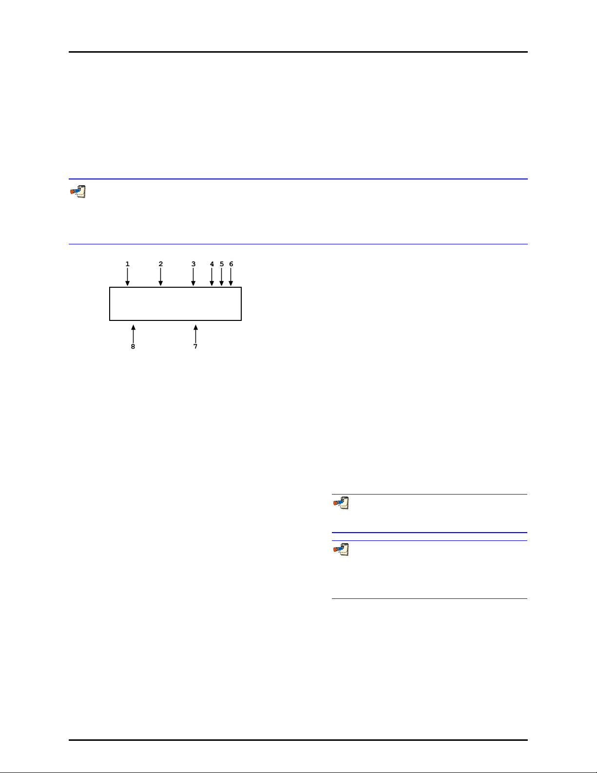
3. GENERAL OPERATION
3.7 MAIN RUN SCREEN
The PG7000 main run screen is its home display that is reached upon powering up and from which other
functions and menus are accessed. It is the top level of all menu structures.
The main run screen is where PG7000 is left in normal operation. It displays the pressure defined by
PG7000, Ready/Not Ready condition and a variety of other information.
The screen described below is called the MAIN run screen. The SYSTEM and AMBIENT screens
(see Sections 3.9.5 and 3.9.6) are also run screens in the sense that all the other functions may be accessed
directly from them and pressure or mass entries may be made from them. See Section 3.8 for a description
of PG7000’s main menu/function structure.
3. <unit>: Current pressure unit of measure (see Section
3.9.3).
prvPRESSURE1 unit aGh
+N.N mm NN.NNNNN kg
1. <prv>: Three Ready/Not Ready indication characters
2. <PRESSURE1>: Numerical value and sign of the
(from left to right: piston position, piston rotation,
vacuum reference) (see Section 3.4). Each character
indicates as follows:
<p>: Piston Position Ready/Not Ready. <*> when
Ready, <↑> when Not Ready due to piston above
measuring zone, <↓> when Not Ready due to piston
below measuring zone, <?> if piston position not
available or out of range. Flashes if condition is Not
Ready and piston is floating (see Section 3.4.1).
Indicates Not Ready when automated pressure
generation is adjusting pressure.
<r>: Piston Rotation Ready/Not Ready. <*> when
Ready, <<> when Not Ready due to piston rotation rate
too low or motorized rotation engaged, <?> if piston
position not available or out of range. Flashes if condition
is Not Ready and piston is floating. (see Section 3.4.2).
<v>: Vacuum Reference Ready/Not Ready
(PG7601 only). <*> when Ready, <v> if Not Ready due
to vacuum not below ready limit. Flashes if condition is
Not Ready and piston is floating (see Section 3.4.3).
pressure defined by PG7000 with current mass loaded
on current piston when all Ready/Not Ready indication
characters indicate Ready.
4. Current measurement mode. <a> for absolute, <g>
for gauge, <d> for differential or high line differential
(see Section 3.9.4).
5. Automated pressure generation status. <G> if automated
pressure generation is ON. The <G> flashes if
automated pressure generation is ON and active, blank
if automated pressure generation is not ON (see
Section 3.9.9).
6. DUT head correction status. <h> if a head correction is
currently being applied, blank if head height is zero (see
Section 3.9.7).
7. <NN.NNNNN kg>: Current mass load in actual mass
(assuming mass loading instructions have been
followed and/or mass loading entries are correct (see
Section 3.6).
8. <± N.N mm>: Current piston position in millimeters
from midstroke position. Positive values are above
midstroke, negative values below. Indicates < ---- >
if piston position not available or out of range (see
Section 3.5).
When a number is too large to display in the
allocated screen space, PG7000 displays <********>
or <OVERFLOW>.
PG7000 has a screen saver function that causes
the display to dim if NO key is pressed for 10 minutes.
Pressing a key restores full power to the display.
The screen saver activation time can be changed or screen
saving can be completely disabled (see Section 3.4.5.1).
Page 45 © 1998-2009 DH Instruments, a Fluke Company
Page 56

PG7000™ OPERATION AND MAINTENANCE MANUAL
3.8 GENERAL FUNCTION/MENU FLOW CHART
Local operator interface with PG7000 is provided by PG Terminal keypad and display. Normal PG7000
operation is organized around run screens from which functions and menus are accessed. The run
screens include:
• MAIN run screen: Displays Ready/Not Ready, defined pressure, piston position and mass load.
• (2) SYSTEM run screens: Display piston position, rotation, temperature and reference vacuum
(PG7601 only).
• AMBIENT run screen: Displays ambient pressure temperature, relative humidity and local gravity.
The flow chart below outlines the operating protocol of the run screens and associated key presses.
POWER
UP
or
RESET
INTRO SCREEN
5 SEC
≈
DELAY
ESC
ESC
TO PREVIOUS
RUN SCREEN
ESC
MAIN RUN SCREEN
SYSTEM
SYSTEM 1
RUN SCREEN
+/-
SYSTEM
or
SYSTEM 2
RUN SCREEN
RES
ENT SPECIAL SETUP
P-C UNIT MODE SYSTEM
AMBIENT
AMBIENT
RUN SCREEN
OTHER FUNCTION KEYS
Figure 9. Run Screen Flow Chart
HEAD
ROTATE
ESCESC
AMBIENT
GEN
© 1998-2009 DH Instruments, a Fluke Company Page 46
Page 57

3. GENERAL OPERATION
3.9 DIRECT FUNCTION KEYS
3.9.1 DIRECT FUNCTION KEYS SUMMARY
Local operator interface with PG7000 is provided by PG Terminal keypad and display.
To minimize the use of multi-layered menu structures, the keypad’s numerical keys also
provide direct access to the most commonly used functions. The function accessed is
labeled on the bottom half of the each key. Direct function keys are active whenever PG7000
is in a run screen (MAIN, SYSTEM or AMBIENT). Table 14 summarizes the operation of the
direct function keys. Section 3.8 provides a flow chart of PG Terminal general operation.
See corresponding manual Sections to 3.9.1 to 3.11.9.
It may be useful to keep a copy of Table 14 near the PG7000, especially when first becoming
acquainted with its operation.
Table 14. Summary of PG7000 Direct Function Key Operations
DIRECT FUNCTION KEYS ARE ACTIVE FROM ANY RUN SCREEN
See corresponding manual sections for full detail.
Menu of less frequently used internal
functions and settings including resets,
user preferences, internal calibration
and remote interface setup.
Edit and select files that determine the
sources of the values for the variables
PG7000 uses in calculations of reference
pressures.
Select pressure to mass or mass to
pressure operation.
(main, ambient, system).
Activate motorized control manually.
Activates when pressed, deactivates
when released.
From a run screen: Access mass or
pressure setting commands.
From other screens: Select menu
choice, enter value, confirm selection.
Turn automatic activation of motorized
rotation ON/OFF.
Turn automated pressure
generation/control ON/OFF, adjust
control parameters, set upper limit for
automated pressure control. Has no
effect if an automated pressure
generation/control component is not part
of the PG7000 system.
Set the resolution of PG7000 mass
loading commands (0.01 g to 0.1 kg).
Access SYSTEM run screens (2) which
display current measurements of piston
behavior, piston-cylinder temperature
and reference vacuum if present.
Toggles between the two screens.
Access AMBIENT run screen which
displays current values of barometric
pressure, ambient temperature, ambient
humidity and local gravity as specified in
the active SETUP file.
Adjust height of DUT fluid head
correction. Set to zero to defeat head
correction.
Select active piston-cylinder module
(range).
Set unit of measure in which pressures
are defined. Choice of units available
from this key can be customized.
Set pressure measurement mode
(gauge, absolute, differential).
Page 47 © 1998-2009 DH Instruments, a Fluke Company
Page 58

PG7000™ OPERATION AND MAINTENANCE MANUAL
3.9.2 [P-C]
PURPOSE
To view and/or change the active piston-cylinder module. In most cases, changing the
piston-cylinder module is equivalent to changing the range.
[P-C] is for selecting the active piston-cylinder module only. Piston-cylinder modules can be
added and deleted and their characteristics can be edited by pressing [SPECIAL] and selecting
<1PC/MS> (see Section 3.11.1).
The active mass set and mass loading bell are selected by pressing [SPECIAL] and selecting
<1PC/MS> (see Section 3.11.1).
PRINCIPLE
To make valid pressure and mass load calculations, PG7000 must know the exact
characteristics of the piston-cylinder module that is currently in use. See Section 7.2 for
detailed information on PG7000 pressure and mass calculations.
Most PG7000s are used with more than one piston-cylinder module. Detailed characteristics
on up to 18 piston-cylinder modules are stored in files. These files can be added, deleted,
viewed and edited by pressing [SPECIAL], 1pc/ms (see Section 3.11.1).
The P-C function provides rapid access, from any run screen, to viewing the piston-cylinder
modules available and selecting one to be active.
OPERATION
Pressing [P-C] activates the piston-cylinder module viewing and selecting function. Pressing
the [P-C] key again or [+/-] while in the P-C function steps through displays of available
piston-cylinder modules.
When [P-C] is first pressed, a summary of the characteristics of the active piston-cylinder
module is displayed, for example:
1. Nominal pressure to mass conversion coefficient of the pistoncylinder module that is currently selected (active). This value is
calculated from the effective area of the piston-cylinder and is
in kPa (if < 1 MPa) or MPa. Upgraded Type 5000 pistoncylinders may be displayed in psi.
2. Serial number of the active piston-cylinder module.
3. Current pressure unit of measure.
4. Nominal pressure in current pressure units resulting from
loading all the mass of the active mass set.
5. Nominal pressure in current pressure units resulting from
loading the piston and mass bell only.
Active 10 kPa/kg 247
0.7 to 50 psi
© 1998-2009 DH Instruments, a Fluke Company Page 48
Page 59

3. GENERAL OPERATION
Pressing [P-C] again or [+/-] causes the screen to step through the other available pistoncylinder modules in the sequence that they were added.
1. Nominal pressure to mass conversion coefficient of the pistoncylinder module. This value is calculated from the effective area
of the piston-cylinder and is always in kPa (if < MPa) or MPa.
2. Serial number of the piston-cylinder module.
3. Current pressure unit of measure.
4. Nominal maximum pressure using the piston-cylinder module.
Pressure, in current pressure units, resulting from loading all
the mass of the active mass set.
5. Nominal minimum pressure using the piston-cylinder module.
Pressure, in current pressure units, resulting from loading the
piston and mass bell only.
Select 200kPa/kg 382
14 to 1000 psi
Pressing [ENTER] while in the P-C function causes PG7000 to select the currently displayed
piston-cylinder module as the active piston-cylinder module.
Pressing [ESCAPE] while in the P-C function returns to the main run screen without
changing piston-cylinder modules.
The pressure unit of measure in which the range offered by the piston-cylinder module using
the active mass set is displayed can be changed by pressing [UNIT] (see Section 3.9.3).
When the current pressure unit of measure is an altitude unit, piston-cylinder module range
is expressed in kPa if the altitude unit is meters (m) or psi if the altitude unit is feet (ft).
3.9.3 [UNIT]
PURPOSE
To specify the unit of measure in which defined pressures are expressed.
PRINCIPLE
PG7000 supports a wide variety of pressure units of measure. Internally, PG7000 always
operates in Pascal [Pa] (the SI unit of pressure). Values of pressure are represented in other
units by the application of conversion factors to convert from Pascal. See Section 7.1.1 for
Unit of Measure Conversions.
The pressure unit of measure selection (e.g., psi, kPa, etc.) is separate from the pressure
measurement mode selection (gauge, absolute or differential). See Section 3.9.4 for
information on changing the measurement mode.
OPERATION
To change the pressure unit of measure, press the
[UNIT] function key from any run screen. The
display is (default units depend on model):
1kPa 2Mpa 3Pa
4bar 5psi 6kcm2
The cursor is on the number corresponding to the active unit. To change the pressure unit, select
the desired unit. The display returns to the previous run screen with the selected unit active.
Page 49 © 1998-2009 DH Instruments, a Fluke Company
Page 60

PG7000™ OPERATION AND MAINTENANCE MANUAL
If the pressure unit selected is inWa, the reference
Select inWa ref temp
temperature for water density must be specified. When
inWa is selected as the unit, the next display is:
4°C 20°C 20°F
Select the desired reference temperature for water density using the [←] or [→] key to move
the cursor. Pressing [ENTER] returns to the main run screen with inWa based on water density
at the selected reference temperature as the active pressure unit. The current inWa
reference temperature can be viewed by observing the position of the cursor in the reference
temperature screen.
See Section 7.1 for tables of the pressure unit of measure conversion factors used by
PG7000.
The UNIT function provides rapid access to a choice of up to six units. The choice of units
can be customized from a wider selection by the user (see Section 3.9.3.1). The default units of the
UNIT function depend on the PG7000 model. The default units are:
PG7102 and PG7601: 1kPa 2MPa 3Pa 4bar 5psi 6kcm2
PG7202 and PG7302: 1MPa 2kPa 3bar 4psi 5kcm2
To restore the default UNIT function settings, use the Unit Reset (see Section 3.11.9.2).
Certain internal and/or metrological functions (e.g., vacuum reference pressure) are always
represented in Pascal [Pa], regardless of the active pressure unit of measure.
When the current pressure unit of measure is an altitude unit, atmospheric pressure in the
AMBIENT run screen is expressed in kPa if the altitude unit is meters (m) or psi if the altitude
unit is feet (ft).
3.9.3.1 CUSTOMIZING PRESSURE UNITS AVAILABLE UNDER THE UNIT FUNCTION
PURPOSE
To customize the selection of pressure units that are available for selection from
the [UNIT] function key.
PRINCIPLE
The UNIT function provides a choice of different pressure units of measure
depending on the PG7000 model. The units that are available by default are
those indicated in the Note in Section 3.9.3. However, PG7000 supports many
other pressure units of measure. Other units can be made available for selection
and units can be deleted by customizing the UNIT function. This allows PG7000
to offer a very wide selection of units while simplifying day to day operation.
The typical user will customize the [UNIT] function key to support the six most
commonly used units.
© 1998-2009 DH Instruments, a Fluke Company Page 50
Page 61

3. GENERAL OPERATION
OPERATION
To customize the [UNIT] function key, from the main run screen press [SETUP]
and select <2PresU>. The display is:
1. The UNIT number in the [UNIT] menu that is
to be changed.
Enter the number of the unit position that
you would like to change. The display
becomes:
Set up user unit #6
Unit #6 1SI 2other
3altitude 4user
Select the desired pressure unit category. SI units include units based on SI
such as mmHg. Select the desired unit from the unit list (see Table 15).
Table 15. Pressure Units of Measure Available
<1SI> <2Other> <3altitude>* <4User>**
<1Pa>
<2Kpa>
<3MPa>
<4mbar>
<5bar>
<6mmHg>
<7mmWa>
* <3altitude>: PG7601 in absolute by vacuum mode only. Not available in
PG7102, PG7202 and PG7302.
** <4user>: User defined unit. As there are no altitude units on PG7102,
PG7202 and PG7302, user is <3user>.
<1psi>
<2psf>
<3inHg>
<4inWa>
<5kcm2>
<6Torr>
<7mTor>
<8none>
<1m>
<2ft>
<1user>
The UNIT function display is not required to display six units. To delete the
current unit from the UNIT screen and show no unit, select <2other>, <6none>
for that unit number.
If <4user> was selected, the user unit must be defined. The display is:
Define user unit:
1. Entry field.
1.000000 Units/Pa
Enter the number of user units per Pascal [Pa] in the entry field. Pressing [ENTER]
defines the user unit and returns to the <Set up unit #> screen.
See Section 7.1.1 for the pressure unit of measure conversion factors used
by PG7000.
The user defined unit can be assigned a user defined label using the UDU
remote command (see Section 4.3.4.2).
Page 51 © 1998-2009 DH Instruments, a Fluke Company
Page 62

PG7000™ OPERATION AND MAINTENANCE MANUAL
3.9.4 [MODE]
PURPOSE
To specify the measurement mode (gauge, absolute, differential) in which PG7000 defines
reference pressures.
Pressure measurement mode and unit of measure are not the same thing.
See Section 3.9.3 for information on the pressure unit of measure.
PRINCIPLE
Pressure defined relative to absolute zero or vacuum is generally referred to as absolute
pressure.
Pressure defined relative to atmospheric pressure is generally referred to as gauge pressure,
with pressure below atmosphere called negative gauge pressure.
Pressure defined relative to another pressure that may be, but is not necessarily atmospheric
pressure, is generally referred to as differential pressure.
PG7000s (depending on the model) can define absolute, gauge, negative gauge and
differential pressures. These are referred to as measurement modes.
The specific PG7000 measurement modes are as follows:
• gauge: Defines gauge pressure by leaving the PG7000 mass load open to
atmosphere. This measurement mode is supported by all PG7000 models. It does not
allow negative gauge pressures. The minimum gauge pressure is the pressure resulting
from loading the combined mass of the piston and the bell on piston-cylinder effective
area.
• absolute by adding atmospheric pressure (absolute by ATM): Defines absolute
pressure by defining a pressure in the same manner as in gauge mode and adding the
value of atmospheric pressure measured by a barometer. This measurement mode is
supported by all PG7000 models. The barometer can be PG7000’s on-board sensor or
a remote RS232 barometer. The uncertainty on the value of atmospheric pressure
measured by the barometer must be considered but this value can become relatively
small as pressure goes up. For example, if using a ± 0.01 % barometer, the added uncertainty
at 1 MPa (150 psi) is 10 ppm.
This mode is more convenient and less costly than absolute by vacuum since no
vacuum reference needs to be established. However, it does not allow absolute
pressures under atmosphere and the minimum absolute pressure is atmospheric pressure
plus the pressure resu lting from loading the combined mass of the piston and the bell on
the piston-cylinder effective area.
• absolute by vacuum (absolute by vac) (PG7601 only): Defines absolute pressure by
measuring relative to an evacuated bell jar. This mode is time consuming as the vacuum
under the bell jar must be made and broken to adjust the mass load for each pressure to
be set. This mode is required for setting absolute pressures under atmospheric pressure
and for lowest uncertainty under about 1 MPa (150 psi).
• differential (dif) (PG7601 only): Defines differential pressures at an absolute static
pressure between vacuum and two atmospheres by defining an absolute pressure
relative to an evacuated bell jar and subtracting static pressure monitored by a digital
pressure indicator. An offsetting technique ensures that only the digital indicator’s
resolution and very short term repeatability influence the measurement results.
Allows positive and negative differential pressure (including gauge pressures) with one
common hardware setup. Covers pressures very near and at zero without limitations
due to piston-cylinder size and mass loads (see Section 3.9.4.1).
© 1998-2009 DH Instruments, a Fluke Company Page 52
Page 63

3. GENERAL OPERATION
• high line differential (HLdif) (PG7102 and PG7202 only): Defines differential
pressures and at gauge static pressure between the lowest gauge pressure supported by
the piston-cylinder and the maximum gauge pressure supported by the piston-cylinder.
Requires the use of a PG7202 or PG7102 as the “reference” and a second gas operated
PG7000 as the “tare”. Differential pressures are defined by setting a common line
pressure on both PG7000s and then adding the differential pressure to the reference
PG7000 (see Section 3.9.4.2).
OPERATION
To change the pressure measurement mode, press [MODE] from any run screen. The resulting
display depends on the PG7000 Model:
Measurement mode:
PG7102, PG7202, PG7302 [MODE] Screen PG7601 [MODE] Screen
1gauge 2abs 3HLdif
Measurement mode:
1g 2avac 3aatm 4dif
For PG7102, PG7202 and PG7302, selecting <2abs> accesses absolute by ATM mode
(see PRINCIPLE above).
For PG7102, PG7202 and PG7302 selecting <3HLdif> accesses high line differential mode
(see PRINCIPLE above and Section 3.9.4.2).
For PG7601, selecting <2avac> accesses absolute by vacuum mode. Selecting <3aatm>
accesses absolute by ATM mode. Selecting <4dif> accesses differential mode
(see PRINCIPLE above and Section 3.9.4.1).
Making a measurement mode selection returns to the previous run screen with the selected
mode active.
The cursor is on the number corresponding to the current measurement mode.
When using an AMH automated mass handler, be sure to apply drive vacuum to the AMH
when switching operation to absolute by vacuum mode (see the AMH-38/AMH-100 Operation and
Maintenance Manual).
3.9.4.1 DIFFERENTIAL MEASUREMENT MODE (PG7601 ONLY)
PURPOSE
To define gauge pressures near and under atmospheric pressure that cannot be
covered in conventional gauge mode; to define pressures at a static pressure
near atmospheric pressure but other than atmospheric pressure.
Differential mode operation is only supported by PG7601. Differential mode
operation requires that the PG7601 SETUP AtmP selection be for an external
barometer connected to COM2 (see Section 3.10, 3.11.5.4). Differential mode
operation also requires the PG7000 Differential Mode Interconnections Kit P/N
3070127, which includes the Differential Mode Controller.
Page 53 © 1998-2009 DH Instruments, a Fluke Company
Page 64

PG7000™ OPERATION AND MAINTENANCE MANUAL
PRINCIPLE
Differential mode is designed to allow PG7601 to define pressures which piston
gauges have typically not covered or for which they have been difficult to use.
This includes positive and negative gauge pressures right around zero, for
example ± 2.5 kPa (10 in. H2O); as well as low differential pressures at low
absolute static pressures, for example 0 to 2.5 kPa (20 Torr) at 15 kPa absolute
(2.2 psia) static pressure.
The principal of differential mode is to define a differential pressure as the
difference between an absolute pressure relative to vacuum and a second
absolute pressure (the static pressure) measured by a precision Reference
Pressure Monitor (RPM). An offsetting procedure “tares” the RPM so that the
uncertainty contributed to the differential pressure by the RPM’s measurement is
a function of the RPM resolution and short term repeatability rather than its
absolute accuracy and long term stability.
For differential mode operation, the static pressure is set to the desired value as
measured by the RPM (atmospheric pressure for gauge pressure
measurements). Then RPM offset at the static pressure is determined by
applying the static pressure as defined by the PG7601 following:
RPM
Where:
PGRPMstart
RPMindicate
= Pressure applied by PG7601 to RPM
=
Once the RPM offset has been determined, differential pressures are defined by
subtracting the static pressure measured by the RPM from an absolute pressure
defined by the PG7601 following:
offset = PGRPMstart - RPMindicate
(nominally equal to RPM
RPM reading when PGRPMstart is applied
to RPM test port
start)
dif = PGabs - RPMcurrent - RPMoffset
PG
Where:
Pgdif
abs
Pg
RPM
RPM
current
offset
= Differential pressure defined by PG7601
= Absolute pressure defined by PG7601
= Current RPM indication of static pressure
= Disagreement between PG7601 and RPM at
the operating static pressure
For differential mode operation, the PG7000 Differential Mode Interconnections
Kit should be used to provide the DUT high and low test connections and support
the RPM offsetting procedure (see Figure 9 and Section 3.9.4.1). A precision
Reference Pressure Monitor, such as a DHI RPM, must be selected for the AtmP
source in SETUP (see Section 3.10, 3.11.5.4).
PG7601 differential measurement mode manages the data acquisition and
handling to support differential mode operation without operator effort.
Differential mode operation requires setting the static pressure at which
differential measurements are to be made and regular determination of the RPM
offset. These functions are supported under [MODE], <4dif>.
© 1998-2009 DH Instruments, a Fluke Company Page 54
Page 65

3. GENERAL OPERATION
1. PG/STATIC P
CONTROL Port
2. PG Port
3. TEST HIGH
Port (Quick
Connection)
4. TEST LOW
Port (Quick
Connection)
5. 1/8 in. NPT F or
4T Quick
Connector
6. STATIC P Port
7. STATIC P
SUPPLY Port
8. CONTROL
SELECTION
Valve
9. PG SHUTOFF
Valve
10. TEST BYPASS
Valve
11. Reference
Pressure
Monitor (RPM)
(Optional)
12. STATIC P
SELECTION
Valve
13. Static Pressure
Exhaust
(Internal)
Figure 10. Differential Mode Controller Schematic
DHI Technical Note 9940TN02 provides more detailed information on
differential mode principles and includes a complete uncertainty analysis. Consult
DHI or visit www.dhinstruments.com.
OPERATION
To select differential mode operation and access differential mode functions
press [MODE] and select <4dif>.
Differential mode operation includes:
• Selecting differential mode, setting static pressure and finding the RPM offset
(see Section 3.9.4.1, Selecting Differential Mode, Setting Static Pressure,
Finding RPM Offset (<1run>).
• Operating in differential mode (see Section 3.9.4.1, Operating In
Differential Mode).
• Viewing differential mode static pressure and RPM offset (see
Section 3.9.4.1, Viewing Static Pressure and RPM Offset (<2view>)
.
• Selecting Differential Mode, Setting Static Pressure, Finding RPM
Offset (<1run>)
Page 55 © 1998-2009 DH Instruments, a Fluke Company
 Loading...