

Page 1
PG7000™ Upgrade Instructions:
Calibration Solutions
for Pressure
and Flow™
Instruction Sheet
Flash with EEPROM to Flash
without EEPROM,
Non-Flash to Flash without EEPROM
INTRODUCTION
For a PG7000 Platform to run ver. 2.02 or higher software, it must be equipped with flash memory, a set of larger
NVRAMs (128K) and jumpers must be installed and the BIOS EPROM must be replaced. Two different upgrade kits
corresponding to two PG7000 Platform hardware situations are available: Upgrade A, P/N 401592 is for PG7000s
that already have flash memory; Upgrade B, P/N 401593 is for PG7000s that do not have flash memory.
• A limited number of PG7000s were delivered between February and July 1999 with ver. 2.00 software. These require Upgrade A
but without the new PG Terminal, use P/N 401594. Refer to the UPGRADING PG7000 PISTON GAUGES FROM ver. 1.0x TO ver.
2.0x commercial document for additional upgrade information.
UPGRADE KIT A, P/N 401592: FLASH WITH EEPROM TO FLASH WITHOUT EEPROM
• If the PG7000 already has ver. 2.00 or 2.01 software, it has a new PG TERMINAL. Use P/N 401594 to upgrade. It does not
include the terminal.
P/N 401592 Parts List
• 4 102091 Shunt, jumper • 1 401284 PG Terminal (not in P/N 401594)
• 1 102542 IC, NVRAM/clock, DS1248Y • 1 550099 Manual, PG7000
• 1 102543 IC, NVRAM, DS1245Y • 1 560037 Instruction sheet, upgrade
• 1 401597 EPROM, PG BIOS ver. 1.02
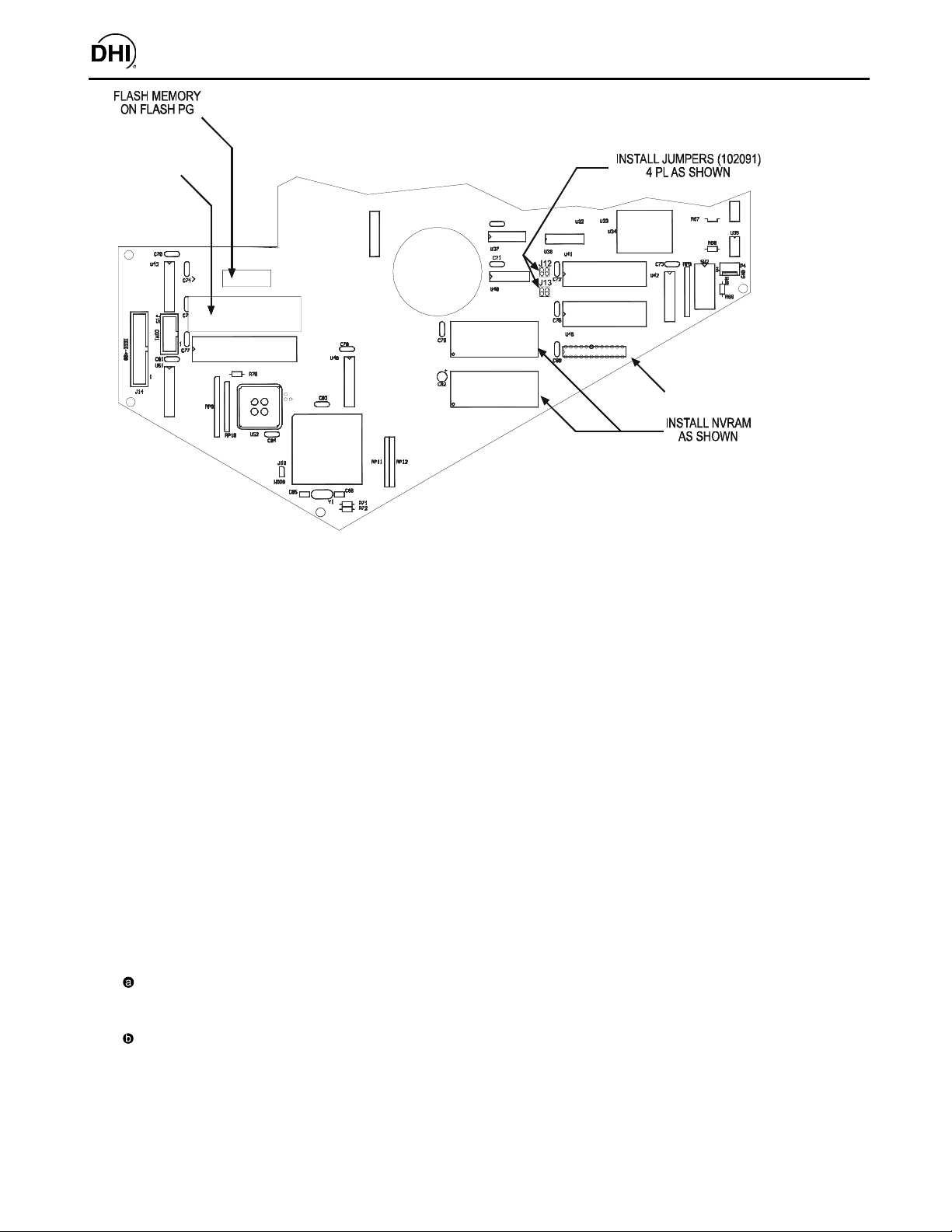
Installation Instructions (see Figure 1)
Open the PG7000 base to expose the electronic board. Use the instructions provided in Section 5.6 of the PG7000
manual supplied with the upgrade kit for assistance on disassembly of the base.
Remove EPROM from U45 and replace with EPROM P/N 401597.
Remove NVRAM DS1230Y from U49 and NVRAM DS1386 from U54.
Insert NVRAM DS1245Y into U49 and NVRAM DS1248Y into U54.
Install two jumper shunts on J12.
Install two jumper shunts on J13.
Flash the PG7000 with PG7000 software ver. 2.02d. (This is available for download at DHI web site:
www.dhinstruments.com). Refer to the instructions provided in Section 5.5 of the PG7000 manual. Remember,
a “null modem” cable must be used to connect the PC to the PG7000 COM2 port.
Reboot the PG7000 following the reboot instructions displayed. When asked whether to upgrade answer, “YES”.
Repeat step and with the most recent PG7000 software version.
PG7000 software upgrades are designed to reformat and transfer data as needed. However, various PG7000 user
settings may be reset and/or deleted. The extent depends on the number of revisions between the original and the
newly flashed version. Be sure to check the metrological aspects including piston-cylinder, mass set, mass bell and
internal sensor calibration files as these may be completely deleted and/or reset. See the PG7000 Manual.
Remove EEPROMS from U41 and U46.
Deliver the upgraded PG7000 Platform to the customer with the new PG Terminal P/N 401284 (not included in
P/N 401594) and the new PG7000 manual P/N 550099.
Page 2
BIOS EPROM ON
FLASH PG
PG7000™ Upgrade Instructions Flash with EEPROM to Flash without EEPROM,
Non-Flash to Flash without EEPROM
U41
U46
U50
PAL
U45
U47
U44
U49
DS1245Y
U54
DS1248Y
U53
Figure 1
UPGRADE KIT B, P/N 401593: NON-FLASH TO FLASH W/OUT EEPROM
P/N 401593 Parts List
• 30 cm 101551-Z Wire, black, 28 AWG • 1 401228 PAL, 68302F, CHIP SELECT
• 4 102091 Shunt, jumper • 1 401596 PCB, PG flash memory adaptor
• 1 102542 IC, NVRAM/clock, DS1248Y • 1 401284 PG Terminal
• 1 102543 IC, NVRAM, DS1245Y • 1 550099 Manual, PG7000
• 1 401597 EPROM, PG BIOS ver. 1.02 • 1 560037 Instruction sheet, upgrade
Installation Instructions (see Figure 2)
NOTE: Installation instructions will vary depending on the software version and the PAL version installed.
Determine what software version is installed: power up the PG and the software version will be displayed on the
PG Terminal.
Open the PG7000 base to expose the electronic board. Use the instructions provided in Section 5.6 of the
PG7000 manual supplied with the upgrade kit for assistance on disassembly of the base.
Determine the PAL version: refer to location U50. A PAL will be installed at this location. The PAL should be
marked with the version number (1.00, 1.01 or 1.03).
For software ver. 1.04X or less; only one EPROM is already installed. Follow “a” and “b” below.
Insert the PG Flash Adaptor, P/N 401596, into the empty location (U45 will be empty for PAL ver. 1.00
and 1.03; U44 will be empty for PAL ver. 1.01).
Remove the old EPROM from either U44 or U45 and insert the new BIOS EPROM, P/N 401597.
Page 3

PG FLASH MEMORY
ADAPTOR (SHOWN @ U45,
SEE INSTRUCTIONS
BELOW FOR ACTUAL
LOCATION)
EPROM ON NON-FLASH
PG (SHOWN @ U44, SEE
INSTRUCTIONS BELOW
FOR ACTUAL
LOCATION)
PG7000™ Upgrade Instructions Flash with EEPROM to Flash without EEPROM,
Non-Flash to Flash without EEPROM
U44
U41
U45
U47
U49
DS1245Y
U54
DS1248Y
U53
U46
U50
PAL
Figure 2
For software ver. 1.05 or higher; EPROM’s are already installed at both U44 and U45. Follow instructions below.
For PAL ver. 1.00 and 1.01, or if the PAL version number is not marked: Remove the PAL from U50.
Insert the new CHIP SELECT PAL, ver. 1.03, P/N 401228, at U50.
Remove EPROMs from locations U44 and U45
Insert the new BIOS EPROM, P/N 401597, at U44
Insert the PG flash adaptor, P/N 401596, at U45
Remove NVRAM DS1230Y from U49 and NVRAM DS1386 from U54.
Insert NVRAM DS1245Y into U49 and NVRAM DS1248Y into U54.
Install two jumper shunts on J12.
Install two jumper shunts on J13.
Using two lengths of the black 28 AWG wire and referring to Figure 2, connect the PG flash adaptor to the PG main
board. Use silicon glue to hold the wire on the board.
Page 4

PG7000™ Upgrade Instructions Flash with EEPROM to Flash without EEPROM,
Non-Flash to Flash without EEPROM
Flash the PG7000 with PG7000 software ver. 2.02d. (This is available for download at DHI web site:
www.dhinstruments.com). Refer to the instructions provided in Section 5.5 of the PG7000 manual. Remember, a
“null modem” cable must be used to connect the PC to the PG7000 COM2 port.
Reboot the PG7000 following the reboot instructions displayed. When asked whether to upgrade answer, “YES”.
Repeat step and with the most recent PG7000 software version.
PG7000 software upgrades are designed to reformat and transfer data as needed. However, various PG7000 user
settings may be reset and/or deleted. The extent depends on the number of revisions between the original and the
newly flashed version. Be sure to check the metrological aspects including piston-cylinder, mass set, mass bell and
internal sensor calibration files as these may be completely deleted and/or reset. See the PG7000 manual.
Remove EEPROMs from U41 and U46.
Deliver the upgraded PG7000 Platform to the customer with the new PG Terminal P/N 401284 and the new PG7000
manual, P/N 550099.
Document 560037c 040514
DH Instruments, Inc.
4765 East Beautiful Lane
Phoenix AZ 85044-5318
USA
Calibration Solutions
for Pressure
and Flow™
Tel 602.431.9100
Fax 602.431.9559
dhi@dhinstruments.com
www.dhinstruments.com
 Loading...