

Page 1

P3800 Series
High Pressure Hydraulic Deadweight Tester
PN 3952319
November 2010
© 2010 Fluke Corporation. All rights reserved. Printed in USA. Specifications are subject to change without notice.
All product names are trademarks of their respective companies.
Users Manual
Page 2

LIMITED WARRANTY AND LIMITATION OF LIABILITY
Each Fluke product is warranted to be free from defects in material and workmanship under normal use and
service. The warranty period is one year and begins on the date of shipment. Parts, product repairs, and
services are warranted for 90 days. This warranty extends only to the original buyer or end-user customer of
a Fluke authorized reseller, and does not apply to fuses, disposable batteries, or to any product which, in
Fluke's opinion, has been misused, altered, neglected, contaminated, or damaged by accident or abnormal
conditions of operation or handling. Fluke warrants that software will operate substantially in accordance
with its functional specifications for 90 days and that it has been properly recorded on non-defective media.
Fluke does not warrant that software will be error free or operate without interruption.
Fluke authorized resellers shall extend this warranty on new and unused products to end-user customers
only but have no authority to extend a greater or different warranty on behalf of Fluke. Warranty support is
available only if product is purchased through a Fluke authorized sales outlet or Buyer has paid the
applicable international price. Fluke reserves the right to invoice Buyer for importation costs of
repair/replacement parts when product purchased in one country is submitted for repair in another country.
Fluke's warranty obligation is limited, at Fluke's option, to refund of the purchase price, free of charge repair,
or replacement of a defective product which is returned to a Fluke authorized service center within the
warranty period.
To obtain warranty service, contact your nearest Fluke authorized service center to obtain return
authorization information, then send the product to that service center, with a description of the difficulty,
postage and insurance prepaid (FOB Destination). Fluke assumes no risk for damage in transit. Following
warranty repair, the product will be returned to Buyer, transportation prepaid (FOB Destination). If Fluke
determines that failure was caused by neglect, misuse, contamination, alteration, accident, or abnormal
condition of operation or handling, including overvoltage failures caused by use outside the product’s
specified rating, or normal wear and tear of mechanical components, Fluke will provide an estimate of repair
costs and obtain authorization before commencing the work. Following repair, the product will be returned to
the Buyer transportation prepaid and the Buyer will be billed for the repair and return transportation charges
(FOB Shipping Point).
THIS WARRANTY IS BUYER'S SOLE AND EXCLUSIVE REMEDY AND IS IN LIEU OF ALL OTHER
WARRANTIES, EXPRESS OR IMPLIED, INCLUDING BUT NOT LIMITED TO ANY IMPLIED WARRANTY
OF MERCHANTABILITY OR FITNESS FOR A PARTICULAR PURPOSE. FLUKE SHALL NOT BE LIABLE
FOR ANY SPECIAL, INDIRECT, INCIDENTAL, OR CONSEQUENTIAL DAMAGES OR LOSSES,
INCLUDING LOSS OF DATA, ARISING FROM ANY CAUSE OR THEORY.
Since some countries or states do not allow limitation of the term of an implied warranty, or exclusion or
limitation of incidental or consequential damages, the limitations and exclusions of this warranty may not
apply to every buyer. If any provision of this Warranty is held invalid or unenforceable by a court or other
decision-maker of competent jurisdiction, such holding will not affect the validity or enforceability of any other
provision.
Fluke Corporation
P.O. Box 9090
Everett, WA 98206-9090
U.S.A.
Fluke Europe B.V.
P.O. Box 1186
5602 BD Eindhoven
The Netherlands
11/99
To register your product online, visit register.fluke.com
Page 3

Table of Contents
Chapter Title Page
1 General Information ............................................................................ 1-1
Introduction........................................................................................................ 1-1
How to Contact Fluke ........................................................................................ 1-1
Safety Information ............................................................................................. 1-2
Symbols Used in this Manual ............................................................................ 1-2
Hydraulic Circuit Schematic.............................................................................. 1-3
2 Preparation .......................................................................................... 2-1
Location ............................................................................................................. 2-1
Fluid Filling ....................................................................................................... 2-1
3 Operation ............................................................................................. 3-1
Connections ....................................................................................................... 3-1
Procedure for Removing Trapped Air from System.......................................... 3-2
Procedure for Priming the Pressure Intensifier.................................................. 3-4
Procedure for Generating System Pressure........................................................ 3-5
Generating Calibration Pressure ........................................................................ 3-6
4 Maintenance......................................................................................... 4-1
Introduction........................................................................................................ 4-1
PCU Removal .................................................................................................... 4-1
Cleaning............................................................................................................. 4-2
Replacement....................................................................................................... 4-3
5 Recalibration........................................................................................ 5-1
Introduction........................................................................................................ 5-1
Do's and Don'ts .................................................................................................. 5-1
Don'ts............................................................................................................. 5-1
Do's................................................................................................................ 5-1
6 Pressure Corrections.......................................................................... 6-1
Introduction........................................................................................................ 6-1
i
Page 4

P3800 Series
Users Manual
Temperature and Gravity Corrections ............................................................... 6-2
ii
Page 5

List of Tables
Table Title Page
1-1. Symbols.................................................................................................................. 1-2
iii
Page 6

P3800 Series
Users Manual
iv
Page 7

List of Figures
Figure Title Page
1-1. Hydraulic Circuit Schematic .................................................................................. 1-3
3-1. Pressure Connection - Method 1 ............................................................................ 3-1
3-2. Pressure Connection - Method 2 ............................................................................ 3-2
3-3. Remove Trapped Air.............................................................................................. 3-2
3-4. Turn Capstan Fully Clockwise............................................................................... 3-3
3-5. Prime the Pressure Intensifier ................................................................................ 3-4
3-6. Generate System Pressure ...................................................................................... 3-5
3-7. Close Reserve Valve .............................................................................................. 3-6
3-8. 5 Correct Float Position ......................................................................................... 3-7
4-1. Piston/Cylinder Removal ....................................................................................... 4-2
6-1. Pressure Corrections............................................................................................... 6-2
6-2. Nomogram for Finding the Value of...................................................................... 6-3
v
Page 8

P3800 Series
Users Manual
vi 1-1
Page 9

Introduction
This manual contains operation and routine and preventive maintenance instructions for
the Model P3830, P3840, and P3860 High Pressure Hydraulic Deadweight Tester (DWT)
manufactured by Fluke. This section of the manual provides general information about
the DWT.
The P3800 Series of Deadweight Testers (DWT) provides a convenient means of testing
high pressure instruments for calibration accuracy.
The design incorporates the “Piston Gauge” principle, in which an applied pressure
within the system, balances a known mass applied to a piston of known effective area. i.e.
Chapter 1
General Information
PRESSURE =
The unit comprises a base plate onto which is mounted a high pressure manifold, a
piston/cylinder unit (PCU), a test station (to mount the equipment under test), a fluid
reservoir, a ram screw pressure generating system, a pressure intensifier (which increases
the pressure generated by a factor of 7:1), and a safety relief valve (which protects both
the low and high pressure systems from accidental overpressure). The whole assembly is
contained within a strong GRP housing.
The unit is equipped with four adjustable feet to enable correct leveling. This ensures that
the PCU is in the vertical plane, which is essential for both accurate and reliable
performance.
The hydraulic fluid supplied with the unit has been specially formulated to remain fluid at
high pressures and to ensure no corrosion of internal parts. In addition the fluid will not
oxidize in contact with air or emulsify or mix with water.
How to Contact Fluke
To order accessories, receive operating assistance, or get the location of the nearest Fluke
distributor or Service Center, call:
• Technical Support USA: 1-800-99-FLUKE (1-800-993-5853)
• Calibration/Repair USA: 1-888-99-FLUKE (1-888-993-5853)
• Canada: 1-800-36-FLUKE (1-800-363-5853)
• Europe: +31-402-675-200
• China: +86-400-810-3435
• Japan: +81-3-3434-0181
• Singapore: +65-738-5655
• Anywhere in the world: +1-425-446-5500
pistontoappliedmassTotal
pistonofareaEffective
Page 10

P3800 Series
Users Manual
Or, visit Fluke's website at www.fluke.com.
To register your product, visit http://register.fluke.com
To view, print, or download the latest manual supplement, visit
http://us.fluke.com/usen/support/manuals
Safety Information
W Warning
Pressurized vessels and associated equipment are potentially
dangerous. The apparatus described in this manual should be
operated by personnel trained in procedures that will assure
safety to themselves, to others, and to the equipment.
W Warning
Please read these instructions carefully prior to installing and
using the Tester. The pressure built up internally during use
can be extremely high. Ensure that all connections are made
correctly.
DO NOT CONNECT DWT TO EXTERNAL PRESSURE SOURCE
Symbols Used in this Manual
In this manual, a Warning identifies conditions and actions that pose a hazard to the
user. A Caution identifies conditions and actions that may damage the Deadweight
Tester (DWT).
.
.
Symbols used on the Deadweight Tester (DWT) and in this manual are explained in
Table 1-1.
Table 1-1. Symbols
Symbol Description
J
Earth Ground
W Important Information: refer to manual
Do not dispose of this product as unsorted
~
municipal waste. Go to Fluke’s website for
recycling information.
1-2
Page 11

General Information
Hydraulic Circuit Schematic 1
Hydraulic Circuit Schematic
RESERVOIR
VALVE
TO TAKE
TEST STATION
ITEM UNDER TEST
FLUID
RESERVOIR
7:1 INTENSIFIER
RELIEF
VALVE
LP VALVEHP VALVE
RAM SCREW
ASSEMBLY
CAPSTAN
ASSEMBLY
PISTON/CYLINDER
Figure 1-1. Hydraulic Circuit Schematic
glf01.eps
1-3
Page 12

P3800 Series
Users Manual
1-4
Page 13

Location
Item number references in the following text, (1), (2), etc, relate to the
hydraulic system schematic, shown in the figures below.
Place the unit onto a clean, flat surface of a strong and rigid workbench.
Ensure that the front of the unit is approximately ¾” / 20 mm from the front edge of the
bench to allow the ram screw capstan to overhang and freely rotate.
Level the DWT by placing the spirit level on top of the weight carrier tube and adjusting
the 4 leveling feet accordingly.
Chapter 2
Preparation
Note
Fluid Filling
Fill the fluid reservoir as follows:
Fully unscrew (counter-clockwise) the reservoir valve screw (3) and remove it together
with the spring and reservoir cover. Place to one side. Fill with the correct fluid to the top
of the brass nut visible on the inside of the reservoir. Fully wind out (counter-clockwise)
the capstan so that fluid is drawn into the DWT. Refill the reservoir to the top of the brass
nut and replace the cover, spring and reservoir valve screw. Fully screw in (clockwise)
the reservoir valve screw and then unscrew (counter-clockwise) again 4 full turns.
The deadweight tester is now ready to receive the Equipment Under Test (EUT).
2-1
Page 14

P3800 Series
Users Manual
2-2
Page 15

Connections
Connect the EUT to the test station using a gauge adapter and lens ring from the selection
provided.
This unit can generate very high pressures and, as a
consequence, only metal-to-metal sealing is acceptable, i.e. no
sealing washers of any description should be used (see Figure
3.1 and 3.2 for methods of sealing).
Chapter 3
Operation
W Caution
Figure 3-1. Pressure Connection - Method 1
glf02.eps
3-1
Page 16

P3800 Series
Users Manual
Figure 3-2. Pressure Connection - Method 2
glf03.eps
Procedure for Removing Trapped Air from System
3-2
Figure 3-3. Remove Trapped Air
glf04.bmp
Page 17
Operation
Procedure for Removing Trapped Air from System 3
1. Open HP valve (1) and LP valve (2) fully, (counter-clockwise).
2. Open reservoir valve (3), (approximately 4 turns counter-clockwise).
3. Turn capstan fully out (counter-clockwise), and wait for approximately 60 seconds.
Figure 3-4. Turn Capstan Fully Clockwise
glf05.bmp
4. Turn capstan fully in (clockwise), and wait for approximately 15 seconds.
5. Trapped air from the system will appear as bubbles in the reservoir.
6. Repeat the procedure until no more air appears in the reservoir.
3-3
Page 18

P3800 Series
Users Manual
Procedure for Priming the Pressure Intensifier
Figure 3-5. Prime the Pressure Intensifier
1. Close LP valve (2) by turning fully clockwise.
2. Turn capstan in (clockwise) until resistance is felt. This is a result of the pressure
required to move the intensifier piston backward in its cylinder, and to lift the
measuring piston and weight carrier.
3. Some additional bubbles may appear in the reservoir.
glf06.bmp
3-4
Page 19

Operation
Procedure for Generating System Pressure 3
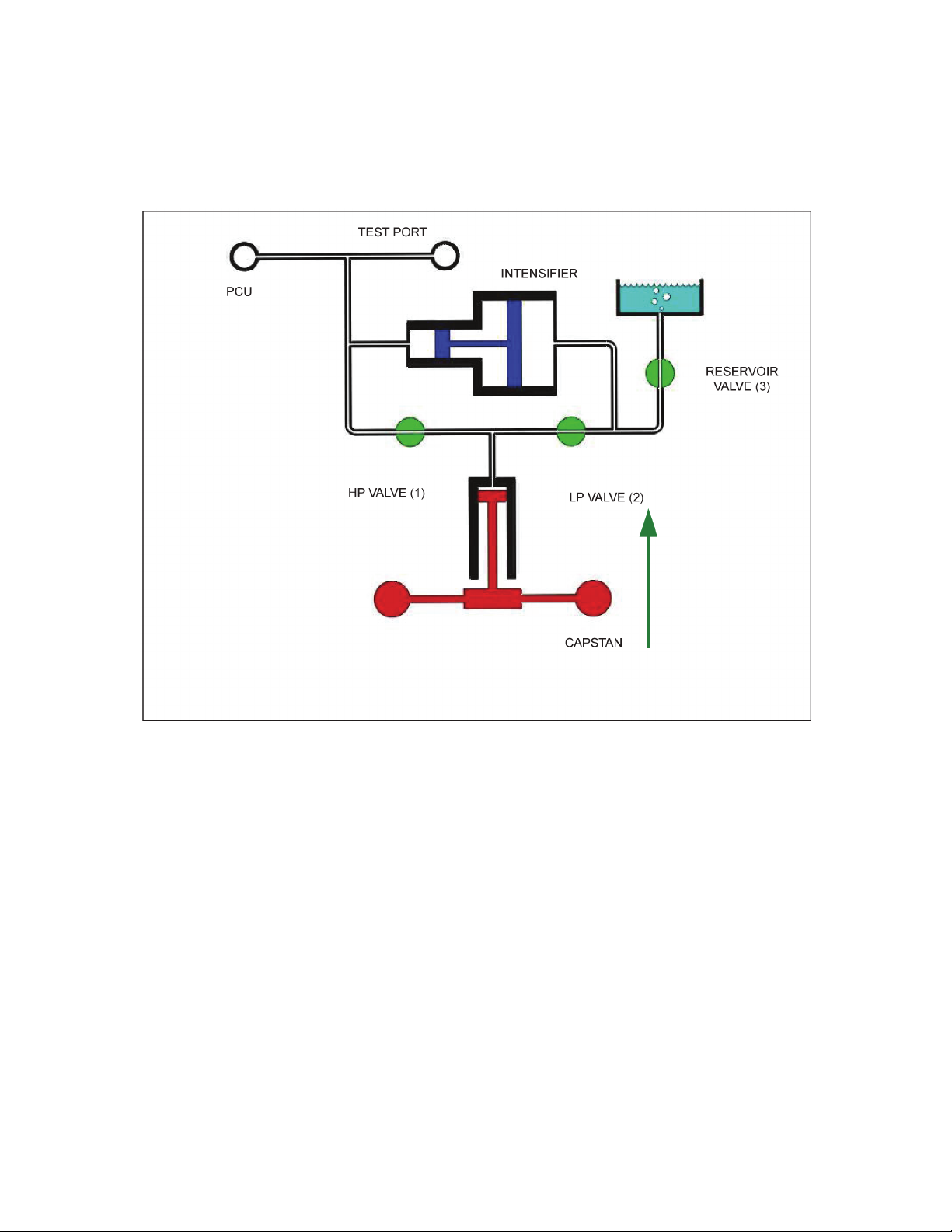
Procedure for Generating System Pressure
TEST PORT
INTENSIFIER
PCU
RESERVOIR
VALVE (3)
HP VALVE (1)
Figure 3-6. Generate System Pressure
LP VALVE (2)
CAPSTAN
1. Close HP valve (1).
2. Open LP valve (2).
3. Turn capstan fully out to prime it with fluid from the reservoir.
glf07.eps
3-5
Page 20

P3800 Series
Users Manual
Figure 3-7. Close Reserve Valve
4. Close reservoir valve (3).
5. Turn capstan in to generate system pressure. The displaced fluid from the ram screw
moves the intensifier piston, generating system pressure to lift the measuring piston
and weights.
Generating Calibration Pressure
To generate any required pressure select weights so that the sum of all the weights (their
pressure equivalents are marked on the top of each weight) PLUS the pressure marked on
the carrier is equal to the pressure required. Load the weights onto the carrier one at a
time, ensuring correct location.
Generate pressure by winding the capstan in (clockwise) until the weight stack starts to
rise. Spin the weight stack in a clockwise direction at approximately 40 rpm by using the
palms of the hands on opposite side of the stack.
Adjust the height of the weight stack winding the capstan in or out until the underside of
the bottom weight lines up with the mid-float position marked on the indicator rod (see
Figure 3-8). The areas above and below the mid-float position indicate the upper and
lower travel limits of the piston assembly.
Before adding or removing weights, it is essential that the weight stack is no longer
spinning.
glf08.bmp
3-6
Page 21

Operation
Generating Calibration Pressure 3
W Caution
When reducing pressure ALWAYS use the capstan (by winding
out counter-clockwise). NEVER use any of the valves.
When reducing from high system pressures, some pressure is
still retained in the system, even after winding the capstan fully
out (approximately 700 psi / 50 bar). To release this pressure
see note below.
Note
To reduce pressure to zero, wind the capstan fully out anticlockwise. Open
HP valve (1) SLOWLY and fully counter-clockwise. Open reservoir valve
(3), four turns anticlockwise.
ADJUST FLOAT HEIGHT OF
PISTON SO THAT THE
UNDERSIDE OF THE BOTTOM
WEIGHT LINES UP WITH THE
MID-FLOAT REFERENCE.
Figure 3-8. Correct Float Position
UPPER TRAVEL LIMIT
MID FLOAT POSITION
LOWER TRAVEL LIMIT
glf09.eps
3-7
Page 22

P3800 Series
Users Manual
3-8
Page 23

Introduction
The P3800 Series of High Pressure Deadweight Testers have been designed to require
minimal maintenance.
Routine maintenance entails keeping the unit clean and free from excess oil.
The operating fluid should be changed at regular intervals due to potential contamination
from items under test. As soon as discoloration of the fluid is observed it should be
replaced as soon as possible.
Chapter 4
Maintenance
If fluid contacts the skin, a mild allergic reaction may result.
Wash at once with soap and water.
Should the PCU require inspection or cleaning, great care must be taken whilst handling
the components.
PCU Removal
Before removal of the PCU, the system pressure must be reduced to zero as described
above.
1. Carefully lift off Weight Carrier Tube Assembly.
2. Unscrew Piston Nut B, and lift out Piston — take great care not to apply any
side-loads to the piston to avoid possible breakage.
3. Unscrew Piston Nut A, taking great care not to drop Cylinder, as it may be inside the
assembly.
The Piston Nut A contains a bearing assembly, which is held in place by a
snap-ring. This should not normally require any maintenance or additional
lubrication.
4. Remove Cylinder.
5. The O Ring Seal under the PCU can now be replaced if required.
W Warning
Note
4-1
Page 24

P3800 Series
Users Manual
PISTON NUT B
PISTON
Cleaning
1. Use “non-fluffing”, non-abrasive, lint-free tissue or absorbent cloth. Hold the Piston
by the larger “head” end, and rub the tissue back and forth along its length.
2. To remove all traces of contamination, the piston can be cleaned in a suitable solvent.
O RING
Figure 4-1. Piston/Cylinder Removal
PISTON NUT A
CYLINDER
PISTON COLUMN
glf10.eps
4-2
W Caution
O-ring seals should not be immersed in solvents, as they will
become damaged. They should be wiped carefully with a new
tissue.
3. After removal from the solvent, using a NEW tissue, repeat the cleaning procedure
above.
4. Place piston carefully on a NEW tissue where it will not be damaged while the
cylinder is cleaned.
Page 25

Maintenance
Replacement 4
W Caution
Never touch the working surface of a clean piston with bare
fingers — the natural oil in your skin can cause the piston and
cylinder to stick.
5. Wipe excess fluid from the outside surfaces of the cylinder.
6. Roll a NEW tissue into a tapered rod of appropriate size. Force the tissue through the
cylinder bore whilst rotating. Ensure that the tissue is a tight fit inside the bore so that
dirt and contamination is removed.
7. Repeat the above step, using a NEW tissue, but from the opposite end of the cylinder.
8. Immerse the cylinder in a suitable, clean solvent, then, using NEW tissues, repeat the
cleaning procedure with the tapered tissue rolls.
Replacement
1. Ensure that the O Ring is clean and undamaged, and that it is fitted correctly in the
top of the PCU Column.
2. Place cylinder on top of the PCU Column, with the reduced diameter at the top,
secure with Piston Nut A.
3. Hold the Piston by the larger “head” end, and dip the smaller “working” end into a
container of CLEAN operating fluid. Transfer this to the top of Piston Nut A, and
allow a few drops of the fluid to run through the bearing assembly and through the
bore of the Cylinder. Repeat this 3 or 4 times to ensure a good film of fluid in the
Cylinder.
4. CAREFULLY introduce the working end of the piston into the Cylinder — ensuring
that it is held VERTICALLY, and push gently through.
W Caution
Never force the piston into its cylinder or damage will result.
5. If resistance is felt, introduce more fluid. If resistance continues, re-clean piston,
cylinder or both. If, after repeated cleaning, the piston still will not slide freely within
the cylinder, then permanent damage may have occurred. In which case, the parts
should be returned to the factory for evaluation or replacement.
6. Screw Piston Nut B onto Nut A to retain the Piston.
7. Carefully replace Weight Carrier Tube Assembly, ensuring that the central hole in the
top locates correctly on the top of the Piston.
4-3
Page 26

P3800 Series
Users Manual
4-4
Page 27

Introduction
To maintain the highest accuracy the DWT should be recalibrated at regular intervals.
The exact period between recalibrations is dependant on ambient conditions and use. As a
general guide, recalibration period should be more than 1 year and less than 3 years.
Do's and Don'ts
Don'ts
• DO NOT release high pressure using any of the valves — ALWAYS use the Capstan
to reduce high pressure before opening any valve.
• DO NOT rotate the Weight Stack at its TOP or BOTTOM position.
• DO NOT remove the GRP cover.
• DO NOT transport with fluid in the system.
• DO NOT allow fluid to fall below the recommended level.
Chapter 5
Recalibration
Do's
• DO change the operating fluid at the first sign of contamination.
• DO have the Deadweight Tester and Weight Set recalibrated at regular intervals.
5-1
Page 28

P3800 Series
Users Manual
5-2
Page 29

Introduction
Pressure correction is required for high accuracy work and is due to the effects of
pressure on the PCU assembly during operation. By reference to the certificate of
calibration provided the actual pressure in the system can be obtained. All values relate to
the environmental conditions stated on the certificate.
The pressure in the system when the carrier is loaded with major weights can be read
directly from the second column of the certificate.
The pressure in the system when the carrier is loaded with incremental weights is given
together with the pressure in the system when the carrier is loaded with major and
incremental weights. From these values, assuming effects are linear, the incremental
weight corrections over the range may be calculated.
Chapter 6
Pressure Corrections
If the DWT is located at a position where the values of the gravitational acceleration and
temperature of the operation are the same as those values specified for calibration, then
the Actual Pressure is fully corrected. If the DWT is used under different conditions then
further correction is necessary. The reference level is specified on the certificate.
Apply temperature
and gravitational correction
CORRECTED
PRESSURE
P1
INDICATED
PRESSURE
(ON WEIGHTS)
Incremental weight
pressure correction
ACTUAL
PRESSURE
P2
Add indicated
carrier pressure
Figure 6-1. Pressure Corrections
glf11.eps
6-1
Page 30

P3800 Series
α
T
H
Users Manual
Temperature and Gravity Corrections
Deadweight testers are manufactured to give an accurate pressure reference at the
specified temperature and gravity values indicated on the certificates. The following
Standard Values are applied during calibration unless otherwise requested during
manufacture (see Certificate).
Standard Gravitational acceleration (
Standard Temperature (T) 20°C
21
Where:
P
1
= Corrected Pressure
P
2
= ACTUAL PRESSURE
= Coefficient of Linear Expansion
(The value for a specific piston / cylinder assembly (PCU) is
shown on the Calibration Certificate)
= DWT calibrated temperature (°C)
t
= Temperature at position of DWT (°C)
g
= Gravitational acceleration at position of DWT
G
= DWT calibrated gravitational acceleration
g
The value of gravitational acceleration (
and geological conditions at the location of the DWT. When the gravitational
acceleration varies from that for which the DWT was calibrated, the above correction
must be made. The local value of gravitational acceleration (
follows:
) varies with latitude, height above sea level
G ) 9.80665 m/s²
()()
g
tTaPP −+= 1
G
g
) can be obtained as
6-2
Data from the appropriate geophysical authority
Approximated from the Nomogram.
Calculated from the formula:
()
Where:
L = geographical latitude,
Height Corrections
Tests carried out at locations other than the test stations may require corrections for fluid
heights. The pressure exerted by a column of fluid 1” / 25.4 mm high will not exceed
0.036 psi / 0.0025 bar using the recommended fluids.
= height above sea level in meters and units of g are m/s²
22
−−+=
HLLg 0000038086.02sin0000059.0sin0053024.017803184.9
Page 31

Pressure Corrections
Temperature and Gravity Corrections 6
Explanation of Nomogram
A straight line passing through the known values of altitude (H)
and latitude (L) of the site of the DWT, when extended to scale
‘g’, will indicate the approximate value of ‘g’.
g
9.83
9.82
9.81
9.80
H16000
14000
90
L
85
80
75
70
65
60
55
50
45
40
12000
10000
8000
35
6000
9.79
30
25
4000
2000
9.78
20
15
10
5
0
9.77
0
0
FEET
9.765
METRES
glf12.eps
Figure 6-2. Nomogram for Finding the Value of "g" from Altitude and Latitude
6-3
Page 32

P3800 Series
Users Manual
6-4
 Loading...