

Page 1

PN 2828192 (English) July 2007
©2007 Fluke Corporation. All rights reserved. Printed in Taiwan.
All product names are trademarks of their respective companies.
MicroMapper™ Pro
VDV Cable Tester
Instruction Sheet
The MicroMapper Pro VDV (Voice, Data, Video) Cable Tester is a hand-held
test instrument that lets you verify and troubleshoot the wiring of twisted
pair and coaxial cables. The tester detects opens, shorts, miswires, and split
pairs. It also includes an analog toner function for locating cables with an
optional tone probe.
The tester comes with the following:
MicroMapper Pro VDV Kit (MMP-KIT)
•
MicroMapper Pro VDV tester with 6 AAA batteries
•
Remote identifiers #1 through #8
•
PRO3000™ Tone Probe with 9 V battery
•
F-connector barrel adapter
•
MicroMapper Pro Instruction Sheet
Page 2

MicroMapper Pro VDV Cable Tester (MMP-50)
•
MicroMapper Pro VDV tester with 6 AAA batteries
•
Remote identifier #1
•
F-connector barrel adapter
•
MicroMapper Pro Instruction Sheet
Safety Information
WWarning
X
To avoid possible fire, electric shock, or personal injury:
•
Do not open the case; no user-serviceable parts are inside.
•
Do not modify the tester.
•
Do not use the tester if it is damaged. Inspect the tester before
use.
•
Do not run a test with cables connected to both connectors on
the tester. Doing so may affect length measurements.
•
If this equipment is used in a manner not specified by the
manufacturer, the protection provided by the equipment may be
impaired.
W
Warning or Caution: risk of damage or destruction to equipment
or software. See explanations in the manual.
X
Warning: Risk of electric shock.
j
This equipment not for connection to public communications
networks, such as active telephone systems.
~
Do not put products containing circuit boards into the garbage.
Dispose of circuits boards in accordance with local regulations.
Page 3
•
The tester is not intended to be connected to active telephone or
network cables, systems, or equipment, including ISDN devices.
Prolonged exposure to the voltages applied by these interfaces
may damage the tester.
•
Do not use the tester if it operates abnormally. Protection may
be impaired.
WCaution
To ensure maximum accuracy of test results replace the batteries
as soon as the low battery () indicator appears.
Contacting Fluke Networks
•
Australia: 61 (2) 8850-3333 or 61 (3) 9329-0244
•
Beijing: 86 (10) 6512-3435
•
Brazil: 11 3044 1277
•
Canada: 1-800-363-5853
•
Europe: +44-(0)1923-281-300
•
Hong Kong: 852 2721-3228
•
Japan: 03-3434-0510
•
Korea: 82 2 539-6311
•
Singapore: 65 6799-5566
•
Taiwan: (886) 2-227-83199
•
USA: 1-800-283-5853
•
Anywhere in the world: +1-425-446-4519
Visit our website for a complete list of phone numbers.
www.flukenetworks.com
support@flukenetworks.com
+1-425-446-4519
Page 4
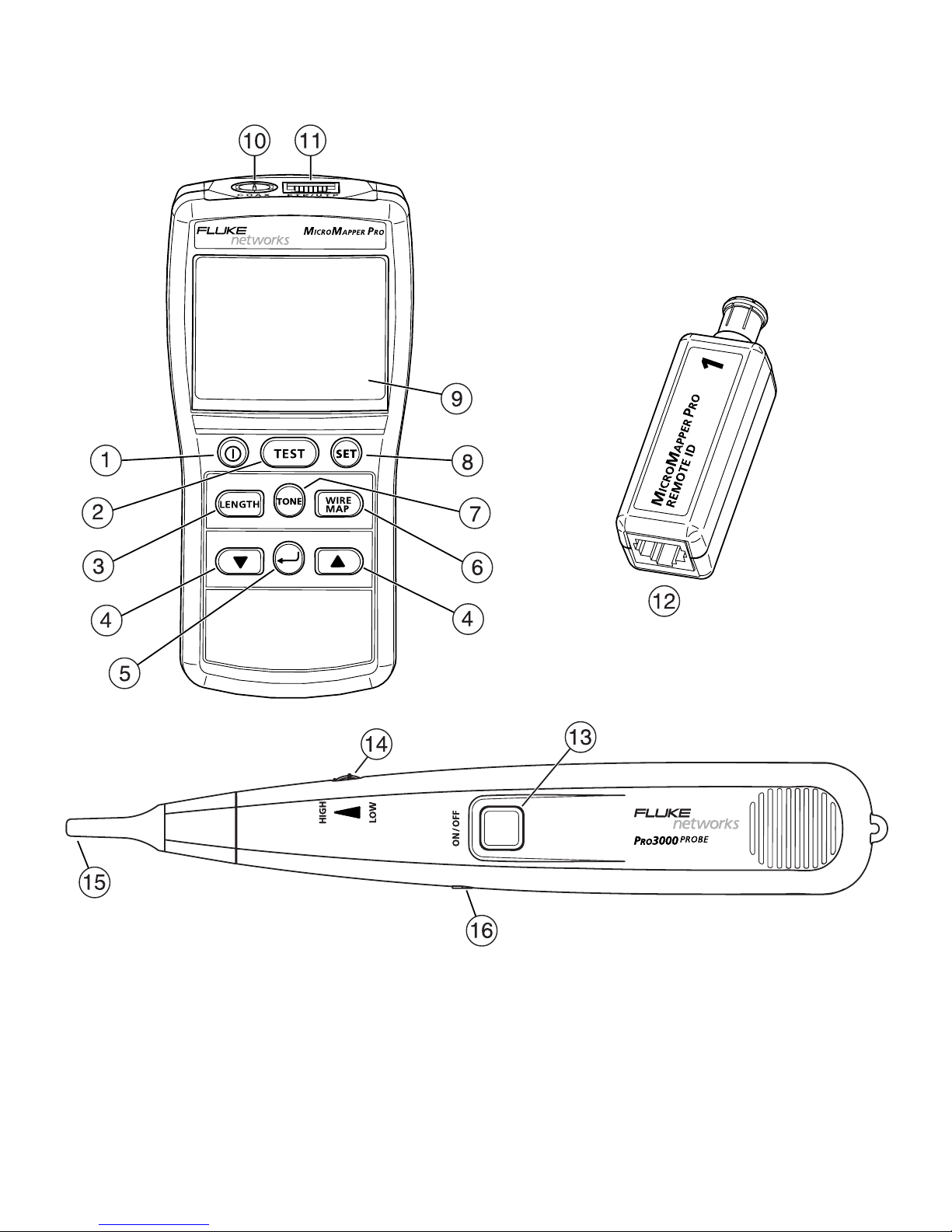
Features
etx01.eps
Page 5

A
Power key.
B
Test key. Tests wire map, measures length, and gives a pass result or
shows faults.
C
Length key. Measures the cable length.
D
Scrolls through a list or displays.
E
Enter key. Selects the setting shown on the display.
F
Wire map key. Tests the wire map.
G
Tone key. Activates the toner.
H
Set key. Accesses setup selections.
I
LCD display.
J
F-connector for connecting to coaxial cables.
K
8-pin modular jack (RJ45) for connecting to UTP and FTP twisted pair
cables.
L
Remote identifier with F-connector and 8-pin modular jack (RJ45).
M
Power key on the optional PRO3000 tone probe.
N
Volume control.
O
Probe tip (not installed). To install the tip, insert it into the hole and turn
it clockwise a quarter turn until it stops.
P
Jack for optional earphone.
Page 6

Battery Installation and Status
WWarningX
To avoid possible electric shock or personal injury:
•
Turn off the tester and disconnect all cables before installing the
batteries.
•
Use only the correct type of batteries, properly installed in the
case, to power the tester and probe.
Installing Batteries in the Tester
1
Remove the battery door screw under the bail on the back of the tester.
2
Install the 6 AAA alkaline batteries, noting the polarity shown in the
battery compartment.
3
Replace the battery door and secure it with the screw.
The tester’s batteries last for about 100 hours of typical use. Replace the
batteries when the low battery indicator ( ) appears.
Installing Batteries in the Optional P
RO3000 Probe
1
Remove the middle screw on the back of the probe.
2
Remove the battery door.
3
Connect the 9 V alkaline battery and place it in the battery compartment,
taking care not to pinch the battery wires.
Replace the probe’s batteries when the probe’s volume weakens or the
probe stops working.
Page 7

Changing the Length Units
1
Turn off the tester.
2
Hold down L; then hold down O until the display shows LEn Unit
(length unit).
3
Press D or C to select a length unit (m or ft).
4
Press A to save the setting.
Setting Up the Tester
Note
You cannot turn off the tester in setup mode.
To change items in the setup menu (listed below), press S; then do the
following:
•
To change an item, press D or C; then press A to save your selection.
•
To scroll past an item without changing it, press A.
•
To exit setup mode, press S. The tester shows SEt PASS (setup pass) to
indicate the setup changes were made successfully. Press T, L, or
W to run a test.
Cable Types
The selected cable type is displayed briefly when you run a test. For twisted
pair cable, the wire size is also shown.
•
CoA CAbLE: coaxial cable
r9-6: RG-6 coaxial cable, 75 Ω
r9-6USEr: RG-6 coaxial cable, 75 Ω, with a user-defined length calibration
parameter
r9-58: RG-58 coaxial cable, 50 Ω
Page 8

r9-58USEr: RG-58 coaxial cable, 50 Ω, with a user-defined length
calibration parameter
•
FtP CAbLE: shielded twisted pair cable
•
UtP CAbLE: unshielded twisted pair cable
CAt5: Category 5 cable
CAt5-USEr: Category 5 cable, with a user-defined length calibration
parameter. Shows as
CAt5-UA-<wire size> when you run a test.
Wire Sizes
A-28, A-26, A-24, A-22
Calibration Mode
•
CAL yES (calibration: yes): Enter length calibration mode. See
“Calibrating Length Measurements”.
•
CAL no (calibration: no): Do not enter length calibration mode.
Beeper
•
bEEP yES: (beeper: yes) Beeper is on.
•
bEEP no: (beeper: no) Beeper is off.
Testing Cables
The cable test checks for wiring faults based on the wire map stored for the
selected cable type and measures the cable length.
A remote identifier is not required for the cable test; however, opens at the
far end and miswires are not detected without a remote identifier.
Page 9

To test a cable:
1
Select the cable type in setup.
2
Connect the cable to the tester. The tester shows no CAbLE (no cable)
when a cable is not connected.
3
Connect a remote identifier to the far end of the cable (optional).
4
Press T.
5
Wire numbers with a fault flash on the display. The EF icons appear if
information is available for additional faults. Use D or C to see the
other faults.
Tables 1, 2, and 3 show examples of cable test results.
Table 1. Test Results for Good Cable
Pass (PASS) results for unshielded, twisted pair
cable.
Remote ID #1 detected.
Pass results for unshielded, twisted pair cable.
No remote ID detected.
Page 10

Results for coaxial cable.
Remote ID #3 detected.
Results for terminated coaxial cable. The tester
shows the total resistance of the cable and
terminator. Length cannot be measured on
terminated cable.
Table 2. Fault Results: Remote Identifier Optional
Short between wires 1 and 2.
The display shows the shorted wires and whether
the short is at the near end (NEAR-END) or far end
(FAR-END) of the cable.
For a short greater than 0 Ω, the displayed length
is greater than the actual distance to the short.
Short to the shield. For shielded cable (FTP) the
shield is shown as H.
The display shows the wire shorted to the shield
(wire 3 in this example).
-continued-
Table 1. Test Results for Good Cable (continued)
Page 11

Open at the near end on wire 3
The display shows the open wires and the most
likely distance to the open.
Split pair on pairs 36 and 45. The wire map may
show some or all of the pairs affected.
Short on coaxial cable.
The display shows the distance to the short.
Table 2. Fault Results: Remote Identifier Optional (continued)
Page 12

Measuring Length
Length measurements are based on nominal parameters for each cable type.
For more accurate measurements, calibrate the tester to the cable under
test. See “Calibrating Length Measurements”.
To measure length:
1
Select the cable type in setup.
2
Connect the cable to the tester.
3
For twisted pair cable, connect a remote identifier to the far end of the
cable (optional).
For coaxial cable, a remote identifier is optional, but the cable must not
be terminated or connected to a device.
4
Press L.
The tester shows a wire map display if a wiring fault prevents the length
measurement.
Table 3. Fault Results: Remote Identifier Required
Miswire. Wires 4 and 5 are swapped.
For shielded cable (FTP) the shield is shown as
H.
Open at the far end on pair 78.
The display shows the open wires and the most
likely distance to the open.
Page 13

5
For twisted pair cable, use D or C to scroll through the length
measurements for each pair. Lengths among pairs may vary up to 5%
because each pair has a different number of twists.
Checking the Wire Map
A remote identifier is required for a complete wire map test. Without a
remote identifier, opens at the far-end connector and miswires are not
detected.
To check the wire map:
1
Select the cable type in setup.
2
Connect the cable to the tester.
3
For twisted pair cable, connect a remote identifier to the far end of the
cable.
For coaxial cable, a remote identifier is optional, but the cable must not
be terminated or connected to a device.
4
Press W. The wire map flashes if a fault is detected.
Table 4 shows examples of wire map displays.
Page 14

Table 4. Wire Map Displays with Remote Identifier
Good cable.
Remote ID #1 detected. Display
shows the WIREMAP indicator.
Opens on pins 2 and 7.
Opens are indicated by a
o. Use
the length test to measure the
distance to opens.
Miswire on pairs 12 and 36.
Short between wires 4 and 5 at
the near end.
1
2
3
4
5
6
7
8
1
2
3
4
5
6
7
8
1
2
3
4
5
6
7
8
1
2
3
4
5
6
7
8
1
2
3
6
1
2
3
6
1
2
3
4
5
6
7
8
1
2
3
4
5
6
7
8
Page 15

Calibrating Length Measurements
Length measurements are based on nominal parameters for each cable type.
Variances in cables from different batches or different manufacturers can
cause length measurements to vary up to 20% for the same cable type.
For more accurate measurements, calibrate the tester to the cable under
test:
1
In the setup menu, select the type of cable to be tested.
2
Connect a good cable of a known length between 15 m and 100 m to the
appropriate connector on the tester. Do not use a patch cord to connect the
cable to the tester.
3
Press S; then press A until the display shows CAL no.
4
Press D so the display shows CAL yES; then press A.
5
Press Sto exit setup mode and enter length calibration mode.
If the attached cable is too short or has some other problem, the display
shows
too 5hort (too short) or bAd CAbLE (bad cable). Check the
connections and the cable; then start again at step 3.
6
Press D or C to adjust the displayed length to match the known length
of the cable; then press A.
The tester shows CAL PASS (calibration pass) to indicate the calibration
was successful.
If the tester shows
CAL FAiL (calibration fail), check the connections and
the cable; then repeat the calibration procedure.
After calibration, the cable type in setup changes to user-defined (
USEr).
Page 16

Hiding the Length Calibration Function
You can hide the length calibration function to prevent changes to the
calibration parameters:
1
Turn off the tester.
2
Hold down Dand C; then press O and wait until the display shows
Hi dE (hide) before releasing the Dand C keys.
3
Press C to select yES (yes).
4
Press A to save the setting. The calibration function no longer appears in
the setup menu.
Using the Toner
Use the toner function with an optional tone probe to locate cables in
bundles, at patch panels, or behind walls.
Note
In toner mode, the tester turns off after 1 hour if no keys are
pressed.
1
Connect the tester to twisted pair or coaxial cable.
2
On the tester, press U to turn on the toner. The display shows SIGNAL TONE,
the tone number (
1 through 4), and a moving pattern of ones while the
toner is active.
3
To change the tone, press Dor C.
4
Use a probe to locate the toner’s signal behind a wall, in a cable bundle, or
at a patch panel. To adjust the P
RO3000 probe’s volume, turn the volume
dial on the side of the probe.
5
To turn off the toner press U, T, L, or W.
Page 17

Maintenance
WWarningX
To avoid possible fire, electric shock, personal injury, or damage
to the tester do not open the case. No user-serviceable parts are
inside.
Cleaning
Clean the display with glass cleaner and a soft, lint-free cloth. Clean the case
with a soft cloth dampened with water or water and a mild soap.
WCaution
To avoid damaging the display or the case, do not use solvents
or abrasive cleansers.
Replacing the Batteries
See “Battery Installation and Status”.
Restoring Factory Defaults
To restore the user-defined length calibration parameters and other settings
to the factory defaults, do the following:
1
Turn off the tester.
2
Hold down T and D; then press O and wait until the display shows
rESEt (reset) before releasing the T and D keys.
3
Press C to select yES (yes); then press A.
Page 18

Accessories
Specifications
Specifications apply at 23 oC (73 oF), unless otherwise noted.
Accessory
Fluke Networks
Model Number
Remote identifier #1 MMP-ID1
MicroMapper remote identifier kit (IDs #2 through #8) MMP-IDK28
Replacement tip for P
RO3000 probe 26100103
Earphone for P
RO3000 probe 26300000
Operating
environment
32 °F to 104 °F (0
o
C to 40 oC) < 80% RH
Storage
environment
-4 °F to +140 °F (-20
o
C to +60 oC) < 70% RH
Shock 1 m drop test
Connectors
Tester: 8-pin modular jack (RJ45), male F-connector
Remote ID: 8-pin modular jack (RJ45), male F-connector
Length test
Range: 1 m to 350 m (2 ft to 999 ft)
Resolution: <100 m: 0.5 m, > 100 m: 1 m
<100 ft: 0.5 ft, >100 ft: 1 ft
Typical accuracy: <150 m: 5% ±1 m (5% ±3 ft)
>150 m: 10% ±1 m (10% ±3 ft)
Typical accuracy of length to a 0 Ω short: UTP/FTP: 7% ±3 m
(7% ±10 ft); Coaxial: 10% ±10 m (10% ±30 ft). Resistance is shown
for a coaxial cable shorted beyond 350 m.
Page 19

Split pairs
Section with split pair must be at least 3 m long and greater than
10% of the cable length.
Coaxial
termination
measurements
Loop resistance between 5 Ω and 350 Ω is considered a
termination resistance. Loop resistance below 5 Ω is considered a
short. Loop resistance greater than 350 Ω is not displayed. Typical
accuracy: 5% ±1 Ω
Ton er
Generates four tones compatible with most analog probes. Tones
are generated on all wire pairs and the coaxial connector.
Calibration
cycle
Factory calibration not required
Display LCD, fixed-segment, 2.19 in x 1.69 in (5.6 cm x 4.2 cm)
Input
protection
50 V dc
Battery type
and life
Tester: 6 AAA alkaline batteries, 100 hours continuous use (nontoner modes), low battery indicator ( ) on display
PRO3000 probe: 9 V alkaline
Auto shutoff
5 minutes with no key presses.
In toner mode, turns off after 1 hour.
Dimensions and
weight
Tester: 5.9 in x 2.8 in x 1.4 in (152 mm x 72 mm x 35 mm), 8.8 oz
(250 g)
Remote ID: 2.4 in x 0.9 in x 0.9 in (60 mm x 23 mm x 22 mm),
1.1 oz (30 g)
P
RO3000 probe: 9.8 in x 1.6 in x 1.3 in (24.9 cm x 4.1 cm x 3.3 cm)
Certifications
and compliance
EN 61326-1, EN 61010
P Conforms to relevant European Union directives.
; Conforms to relevant Australian standards.
Page 20

LIMITED WARRANTY AND LIMITATION OF LIABILITY
Fluke Networks mainframe products will be free from defects in material and workmanship for 1 year from the date of purchase. Parts, accessories, product repairs and services are warranted for 90 days, unless otherwise stated. Ni-Cad, Ni-MH and Li-Ion
batteries, cables or other peripherals are all considered parts or accessories. This warranty does not cover damage from accident, neglect, misuse, alteration, contamination,
or abnormal conditions of operation or handling. Resellers are not authorized to extend
any other warranty on Fluke Networks’ behalf. To obtain service during the warranty
period, contact your nearest Fluke Networks authorized service center to obtain return
authorization information, then send your defective product to that Service Center with
a description of the problem.
THIS WARRANTY IS YOUR ONLY REMEDY. NO OTHER WARRANTIES, SUCH AS FITNESS
FOR A PARTICULAR PURPOSE, ARE EXPRESSED OR IMPLIED. FLUKE NETWORKS IS NOT
LIABLE FOR ANY SPECIAL, INDIRECT, INCIDENTAL OR CONSEQUENTIAL DAMAGES OR
LOSSES, ARISING FROM ANY CAUSE OR THEORY. Since some states or countries do not
allow the exclusion or limitation of an implied warranty or of incidental or consequential damages, this limitation of liability may not apply to you.
Fluke Networks
PO Box 777
Everett, WA 98206-0777
USA
4/04
 Loading...