

Page 1

FOM, FOS 850, FOS 1300, FOS 850/1300
Fiber Optic Power Meter
Fiber Optic Light Source
Instruction Sheet
Introduction
The Fiber Optic Power Meter (FOM) measures optical power on
fiber optic cables. An FOM indicates any power loss on tested
cables using any digital multimeter (DMM) or graphical
multimeter (GMM) that has a 10 MΩ input impedance, standard
diameter banana jacks, and mVdc capability. The Fiber Optic
Light Source (FOS) is used as a light source with the FOM or
other fiber optic meters.
Safety Information
All FOSs have been tested according to IEC 1010-1 and
IEC 825-1 and meet all requirements for a Class 1 LED Product.
To ensure the FOS is used safely, read the following warnings:
P Warning P
To avoid possible exposure to hazardous invisible LED
radiation and to prevent eye damage:
• Never look directly into the aperture (Figure 2) of the ST
connector.
• Do not open the case; no serviceable parts are inside.
Send the source to a authorized service center for
calibration or repair.
• Do not adjust or modify the source; LED sources may
exceed Class 1.
• Do not use magnification at the ST connector output.
• Caution - Use of controls or adjustments, or performance
of procedures other than those specified herein may
result in hazardous radiation exposure.
®
PN 200631 May 1996 Rev. 2, 2/97
1996, 1997 Fluke Corporation. All rights reserved. Printed in U.S.A.
Page 2
FOM Features
DMM Plugs
FOM
FIBER
OPTIC
METER
1550
1300
850
OFF
Figure 1. Fiber Optic Power Meter
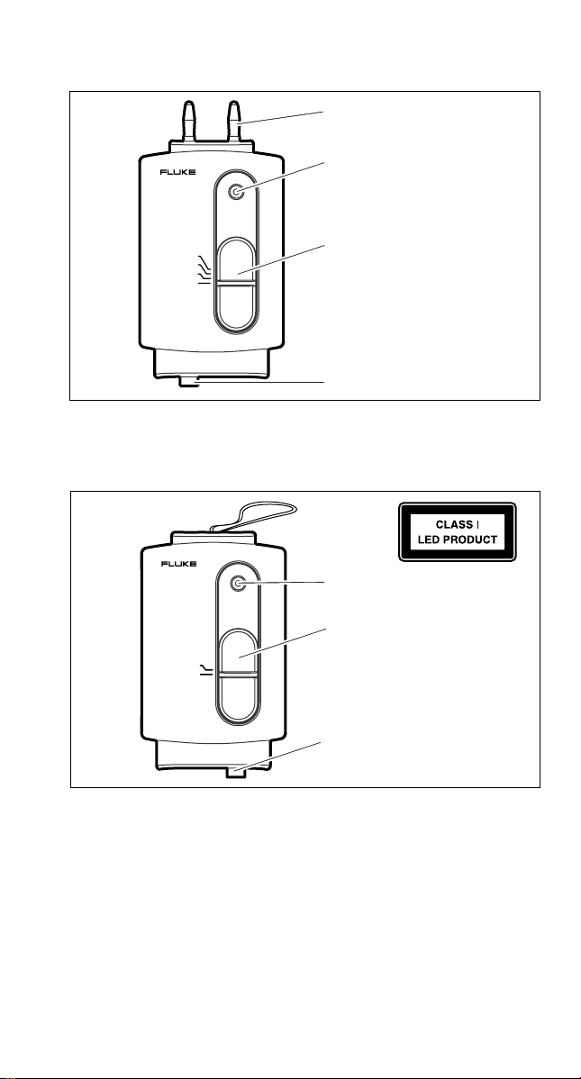
FOS Features
FOS 850
FIBER
OPTIC
SOURCE
850
OFF
Battery Indicator LED
Function Switch
Input Connector (ST)
aj1f.eps
Battery Indicator LED
Function Switch
Output Aperture
Connector (ST)
Figure 2. Fiber Optic Light Source (850 Source Shown)
Clean Connectors
Turn the FOS off before cleaning. To ensure proper operation,
clean internal portion of connectors with a low-lint optical grade
cleaning swab and optical grade alcohol, and a can of filtered
compressed air.
aj2f.eps
Page 3

Measuring dB Loss
To measure dB loss, refer to Figures 3 and 4 and do the
following:
4
mV
mV
5
3
mV
6
1
Receive
Cable
Figure 3. Measuring Output for Source Reference
2
Cable
aj3f.eps
1. Clean the connectors and fiber ends with alcohol and check
for fiber bends. Connect the receive cable to the FOM and
the launch cable to the FOS.
2. Connect the launch and receive cables with a coupling
(P/N 602810 or equivalent).
3. Plug the FOM into the DMM or GMM with the red polarity
indicator aligning with the voltage input.
4. Select mVdc on the DMM.
5. Select the desired wavelength on the FOM.
6. Select the desired wavelength on the FOS and stabilize (20
minutes).
7. Record the dBm reference measurement (1 dBm = 1 mVdc)
on the DMM display (or if you have a DMM with a reference
function, activate the reference function).
Note
The reference measurement on the display should
closely match the output level specified for the optical
source (approximately -20 dBm into multimode fiber).
8. When finished, disconnect the launch and receive cables
from the coupling.
Note
To measure dB loss accurately, do not disturb the
connections to the FOM and FOS after measuring the
source output.
Launch
Page 4

mV
mV
mV
Cable
Under
Test
Patch
Panel
Receive
Cable
FOM
Launch
FOS
Cable
Figure 4. Measuring Optical Loss
aj4f.eps
9. Connect the launch and receive cables to cable under test;
record the measurement. (Cables must be the same fiber
type as the cable under test.)
10. Subtract the optical loss measurement from the dBm
reference measurement to get the actual dB loss. (If the
DMM has an activated reference function, the reading is dB
loss.)
Checking the Battery
If the LED is on continuously, the battery is good.
If the LED blinks or is not on, replace the battery.
Page 5

Replacing the Battery
To replace the battery, refer to Figure 5.
Figure 5. Battery Replacement
General Specifications
Power Meter Specifications
Output: 1 mV per 1 dB
Input Connector Type: Fixed ST
Photodetector Type: Germanium
Application Range: 800 to 1600 nm
Calibrated wavelengths: 850, 1300, and 1550 nm
Acceptable fiber ty pes
(sizes): 9/125 t o 100/ 140 µm
Operating range: +3 to -50 dBm
Maximum power level: +5 dBm
Absolute accuracy: ±0.25 dB, (Specified at 25°C &
Relative accuracy: ±0.15 dB, (Specified ov er any 10 dB
Repeatability: ±0.04 dB
Battery type: 9V alkaline, NEDA 1604A or IEC 6LR61
Battery life: 16 hours minimum, 100 hours ty pi cal, 9V
Low battery indication: Blinking LED indicator
Operating temperature: 0 to +40°C
Storage temperature: -20 to +70°C
Humidity: 0 to 40°C, up to 75% RH
Electromagnetic
Compatibility:
RF Field ≤1 V/m
RF Field = 3 V/m
-10.0 dBm per NIST standard)
within measurement range)
alkaline
Total Accuracy =
Specified Accurac y
Specified Accurac y + 2.5 dB
aj5f.eps
Page 6

Source (850, 1300, 850/1300) Specifications
Type: Infrared LED
Wavelength:
Output power: -20 dBm , nominal into 62.5/125 micron
Output connector type: Fix ed ST
Beam divergence: 0.3 radians
Pulse duration: Continuous wave
Maximum output: 200 µW (radiated into free space)
Stability: ±0.2 dB per 8 hours at 20°C after 20
Temperature coefficient: -0.08 dB per °C, < 18°C or > 28°C
Battery type: 9V alkaline, NEDA 1604A or IEC 6LR61
Battery life: 16 hours minimum, 24 hours ty pi cal, 9V
Low battery indication: Blinking LED indicator
Operating temperature: 0 to +40°C
Storage temperature: -20 to +70°C
Humidity: 0 to 40°C, up to 75% RH
850 ± 30 nm
1300 ± -40/+50 nm
850/1300 ± 30 nm, -40/+50 nm
multimode fiber
minute warmup
alkaline
Service
For service information in the U.S.A., call 1-800-825-9810.
Outside the U.S.A., contact an authorized service center.
To locate an authorized service center, visit us on the World
Wide Web: www.fluke.com or call Fluke using any of the phone
numbers listed below:
1-800-443-5853 in U.S.A and Canada
31 40 267 8200 in Europe
206-356-5500 from other countries
 Loading...