

Page 1

DSP-4000 Series
CableAnalyzer
Users Manual
July 2001
© 2000, 2001 Fluke Networks, Inc. All rights reserved. Printed in USA.
All product names are trademarks of their r espective comp ani es.
Page 2

LIMITED WARRANTY & LIMITATION OF LIABILITY
Each Fluke Networks product is warranted to be free from defects in material and workmanship
under normal use and service. The warranty period is one year and begins on the date of purchase.
Parts, accessories, product repairs and services are warranted for 90 days. This warranty extends
only to the original buyer or end-user customer of a Fluke Networks authorized reseller, and does not
apply to disposable batteries, cable connector tabs, cable insulation-displacement connectors, or to
any product which, in Fluke Networks’ opinion, has been misused, altered, neglected, contaminated,
or damaged by accident or abnormal conditions of operation or handling. Fluke Networks warrants
that software will operate substantially in accordance with its functional specifications for 90 days and
that it has been properly recorded on non-defective media. Fluke Networks does not warrant that
software will be error free or operate without interruption.
Fluke Networks authorized resellers shall extend this warranty on new and unused products to enduser customers only but have no authority to extend a greater or different warranty on behalf of Fluke
Networks. Warranty support is available only if product is purchased through a Fluke Networks
authorized sales outlet or Buyer has paid the applicable international price. Fluke Networks reserves
the right to invoice Buyer for importation costs of repair/replacement parts when product purchased
in one country is submitted for repair in another country.
Fluke Networks’ warranty obligation is limited, at Fluke Networks’ option, to refund of the purchase
price, free of charge repair, or replacement of a defective product which is returned to a Fluke
Networks authorized service center within the warranty period.
To obtain warranty service, contact your nearest Fluke Networks authorized service center to obtain
return authorization information, then send the product to that service center, with a description of the
difficulty, postage and insurance prepaid (FOB Destination). Fluke Networks assumes no risk for
damage in transit. Following warranty repair, the product will be returned to Buyer, transportation
prepaid (FOB Destination). If Fluke Networks determines that failure was caused by neglect, misuse,
contamination, alteration, accident or abnormal condition of operation or handling, or normal wear
and tear of mechanical components, Fluke Networks will provide an estimate of repair costs and
obtain authorization before commencing the work. Following repair, the product will be returned to
the Buyer transportation prepaid and the Buyer will be billed for the repair and return transportation
charges (FOB Shipping Point).
THIS WARRANTY IS BUYER’S SOLE AND EXCLUSIVE REMEDY AND IS IN LIEU OF ALL
OTHER WARRANTIES, EXPRESS OR IMPLIED, INCLUDING BUT NOT LIMITED TO ANY
IMPLIED WARRANTY OF MERCHANTABILITY OR FITNESS FOR A PARTICULAR PURPOSE.
FLUKE NETWORKS SHALL NOT BE LIABLE FOR ANY SPECIAL, INDIRECT, INCIDENTAL OR
CONSEQUENTIAL DAMAGES OR LOSSES, INCLUDING LOSS OF DATA, ARISING FROM ANY
CAUSE OR THEORY.
Since some countries or states do not allow limitation of the term of an implied warranty, or exclusion
or limitation of incidental or consequential damages, the limitations and exclusions of this warranty
may not apply to every buyer. If any provision of this Warranty is held invalid or unenforceable by a
court or other decision-maker of competent jurisdiction, such holding will not affect the validity or
enforceability of any other provision.
6-01
Fluke Networks, Inc.
PO Box 777
Everett, WA 98206-0777
USA
Page 3

Table of Contents
Chapter Page
1 Introduction...................................................................................... 1-1
Contacting Fluke Networks............................................................................. 1-1
Registration ..................................................................................................... 1-2
Overview of Features ...................................................................................... 1-2
Standard Accessories....................................................................................... 1-4
Using This Manual.......................................................................................... 1-6
2 Getting Started................................................................................. 2-1
Read First: Safety and Operational Information.............................................. 2-1
Quick Start....................................................................................................... 2-4
Powering the Test Tool............................................................................. 2- 4
Using the Menus....................................................................................... 2-4
Using the Link Interface Adapters............................................................ 2-5
Formatting the Memory Card (DSP-4100/4300)...................................... 2-6
Quick Configuration................................................................................. 2-8
Results within Accuracy Range................................................................ 2-9
Autotest on Twisted Pair Cabling............................................................. 2-10
Saving Test Reports.................................................................................. 2-11
Using the Talk Mode ................................................................................ 2-15
Autotest on Coaxial Cabling..................................................................... 2-16
Main Unit Features.......................................................................................... 2-18
Remote Features.............................................................................................. 2-21
Link Interface Adapter Features...................................................................... 2-23
Permanent Link Interface Adapters (DSP-4000PL/4300)........................ 2-24
Changing the Personality Module (DSP-4000PL/4300)........................... 2-25
Strap and Bail.................................................................................................. 2-26
Rotary Switch.................................................................................................. 2-26
Off............................................................................................................. 2-26
Autotest..................................................................................................... 2-27
Single Test ................................................................................................ 2-28
i
Page 4

DSP-4000 Series
Users Manual
Turning On the Test Tool ............................................................................... 2-31
Configuring the Test Tool............................................................................... 2-33
Remote Lights, Messages, and Audible Tones............................................... 2-43
Remote Communication Error........................................................................ 2-43
Battery Status.................................................................................................. 2-44
Battery Status Display..................................................................................... 2-44
Monitor..................................................................................................... 2-29
Setup......................................................................................................... 2-29
Print.......................................................................................................... 2-30
Special Functions ..................................................................................... 2-30
Selecting a Language for Displays and Reports....................................... 2-31
Performing a Self-Test............................................................................. 2-32
Overvoltage Test...................................................................................... 2-32
Noise Test................................................................................................. 2-33
Controlling the Backlight......................................................................... 2-33
Adjusting the Display Contrast ................................................................ 2-34
Selecting a Power Line Filter Frequency ................................................. 2-34
Selecting a Test Standard and Cable Type............................................... 2-35
Editing the Report Identification.............................................................. 2-36
Setting Up Cable IDs................................................................................ 2-37
Viewing the Cable ID Configuration and Memory Status ....................... 2-40
Storing Plot Data with Saved Autotest Results (DSP-4100/4300)........... 2-40
Selecting a Length Unit............................................................................ 2-40
Selecting a Numeric Format..................................................................... 2-41
Setting the Date and Time........................................................................ 2-41
Setting the Power-Down Timer................................................................ 2-42
Enabling or Disabling the Audible Tones ................................................ 2-42
3 Autotest............................................................................................ 3-1
Autotest Softkeys............................................................................................ 3-1
Autotest on Twisted Pair Cabling................................................................... 3-2
Link Performance Grade Result (Headroom)................................................. 3-6
Worst Margin and Worst Value Results......................................................... 3-6
Automatic Diagnostics.................................................................................... 3-7
Autotest Results for Twisted Pair Cabling...................................................... 3-8
Wire Map Test.......................................................................................... 3-8
Resistance................................................................................................. 3-10
Length....................................................................................................... 3-10
Propagation Delay and Delay Skew......................................................... 3-11
Characteristic Impedance......................................................................... 3-11
Attenuation (Insertion Loss)..................................................................... 3-12
NEXT Test ............................................................................................... 3-14
NEXT@REMOTE................................................................................... 3-16
ELFEXT Test ........................................................................................... 3-16
ACR.......................................................................................................... 3-19
ii
Page 5

Contents
(continued)
ACR@REMOTE...................................................................................... 3-21
Return Loss (RL)...................................................................................... 3-21
RL@REMOTE......................................................................................... 3-23
PSNEXT (Power Sum NEXT) and PSNEXT@REMOTE....................... 3-23
PSELFEXT (Power Sum ELFEXT)......................................................... 3-23
PSACR (Power Sum ACR) and PSACR@REMOTE.............................. 3-23
Autotest on Coaxial Cabling........................................................................... 3-23
Autotest Results for Coaxial Cabling.............................................................. 3-25
Characteristic Impedance.......................................................................... 3-25
Resistance ................................................................................................. 3-26
Length....................................................................................................... 3-26
Anomaly.................................................................................................... 3-26
Saving Autotest Results................................................................................... 3-27
Saving Results with Auto Sequence Disabled.......................................... 3-27
Saving Results with Auto Sequence Enabled........................................... 3-29
Saving Results with Downloaded Cable IDs (DSP-4300)........................ 3-30
Changing the Cable ID for a Saved Autotest Report................................ 3-30
If Memory is Full...................................................................................... 3-31
Saving Results to Internal Memory (DSP-4300)...................................... 3-31
The Autotest Report ........................................................................................ 3-32
4 Running Individual Tests................................................................. 4-1
Single Tests for Twisted Pair Cabling............................................................. 4-1
Scanning Function........................................................................................... 4-2
When to Use a Remote Unit............................................................................ 4-2
Running a Single Test on Twisted Pair Cabling.............................................. 4-4
The HDTDX Analyzer.................................................................................... 4-6
Running the HDTDX Analyzer................................................................ 4-6
HDTDX Analyzer Results........................................................................ 4-7
HDTDX Analyzer Plot ............................................................................. 4-8
The HDTDR Test............................................................................................ 4-9
How to Terminate the Cable..................................................................... 4-9
Running the HDTDR Test on Twisted Pair Cabling ................................ 4-11
Running the HDTDR Test on Coaxial Cabling........................................ 4-11
HDTDR Results Screen............................................................................ 4-12
HDTDR Plot Screen ................................................................................. 4-12
Single Test Results for Twisted Pair Cabling.................................................. 4-14
Wire Map.................................................................................................. 4-14
Length....................................................................................................... 4-14
NEXT and NEXT@REMOTE ................................................................. 4-14
ELFEXT.................................................................................................... 4-14
Impedance................................................................................................. 4-15
Attenuation (Insertion Loss)..................................................................... 4-15
Resistance ................................................................................................. 4-15
iii
Page 6

DSP-4000 Series
Users Manual
Return Loss (RL) and RL@REMOTE..................................................... 4-15
Power Sum NEXT and Power Sum NEXT@REMOTE.......................... 4-15
Power Sum ELFEXT................................................................................ 4-15
Single Tests for Coaxial Cabling.................................................................... 4-16
Running a Single Test on Coaxial Cabling .............................................. 4-16
Single Test Results for Coaxial Cabling................................................... 4-18
Monitoring Network Activity......................................................................... 4-19
Identifying Hub Port Connections .................................................................. 4-22
Monitoring Impulse Noise.............................................................................. 4-22
Changing the Impulse Noise Threshold ................................................... 4-23
Running the Impulse Noise Test.............................................................. 4-23
Noise Test Results.................................................................................... 4-25
Determining Hub Port Capabilities................................................................. 4-26
Using the Tone Generator............................................................................... 4-26
5 Viewing and Printing Saved Reports.............................................. 5-1
Viewing, Renaming, and Deleting Test Reports............................................. 5-1
Printing Test Reports ...................................................................................... 5-2
Configuring the Serial Port....................................................................... 5-3
Printer Interface Cable.............................................................................. 5-3
Printing..................................................................................................... 5-4
If the Printer Does Not Respond.............................................................. 5-6
6 Calibrations and Custom Test Standards...................................... 6-1
Calibrating the Test Tool................................................................................ 6-1
Calibrating the Permanent Link Adapters....................................................... 6-3
NVP Calibration.............................................................................................. 6-3
Configuring a Custom Test............................................................................. 6-4
7 Basic Cabling Testing...................................................................... 7-1
LAN Cable Construction ................................................................................ 7-1
Twisted Pair Cable ................................................................................... 7-2
Coaxial Cable........................................................................................... 7-4
Basic Link Connections.................................................................................. 7-5
Channel Connections...................................................................................... 7-6
Permanent Link Connections.......................................................................... 7-7
Attenuation (Insertion Loss)........................................................................... 7-8
Noise............................................................................................................... 7-9
Characteristic Impedance................................................................................ 7-10
Minimizing Impedance Discontinuities.......................................................... 7-11
Crosstalk ......................................................................................................... 7-11
NEXT.............................................................................................................. 7-12
FEXT and ELFEXT........................................................................................ 7-12
Locating NEXT and ELFEXT Problems........................................................ 7-14
iv
Page 7

Contents
(continued)
Split Pairs and NEXT................................................................................ 7-16
Minimizing Crosstalk................................................................................ 7-17
Power Sum Values .......................................................................................... 7-17
Propagation Delay and Delay Skew................................................................ 7-18
Nominal Velocity of Propagation (NVP)........................................................ 7-19
NVP and Length Measurements............................................................... 7-20
NVP Calibration ....................................................................................... 7-20
High-Definition Time Domain Reflectometry (HDTDR)............................... 7-20
Reflections from Opens............................................................................ 7-21
Reflections from Shorts............................................................................ 7-22
Reflections from Other Anomalies........................................................... 7-22
Cable Termination .................................................................................... 7-23
Interpreting the HDTDR Plot.................................................................... 7-23
ACR................................................................................................................. 7-24
RL.................................................................................................................... 7-26
Troubleshooting Basics................................................................................... 7-27
8 Maintenance and Specifications..................................................... 8-1
Getting Software Upgrades............................................................................. 8-1
Maintenance.................................................................................................... 8-1
Cleaning and Storage................................................................................ 8-2
Replacing the NiMH Battery Pack............................................................ 8-2
Internal Lithium Backup Battery.............................................................. 8-3
If the Test Tool Fails....................................................................................... 8-3
Service Center Repair............................................................................... 8-3
Replacement Parts..................................................................................... 8-5
Options and Accessories........................................................................... 8-6
Specifications.................................................................................................. 8-8
Calculated Measurement Accuracy.......................................................... 8-8
Traceable Calibration Period.................................................................... 8-8
Self-Calibration Period............................................................................. 8-8
Compatibility with Remotes and Link Interface Adapters ....................... 8-9
Standard Link Interface Adapters............................................................. 8-9
Cable Types Tested................................................................................... 8-10
Test Standards........................................................................................... 8-11
Time for Autotest...................................................................................... 8-11
Length....................................................................................................... 8-12
Propagation Delay..................................................................................... 8-12
Delay Skew............................................................................................... 8-12
DC Loop Resistance Test.......................................................................... 8-12
Measurement Accuracy as Specified in Relevant Standards.................... 8-13
Typical Measurement Accuracies............................................................. 8-14
HDTDX Analyzer Specifications for Cables <100 m (328 ft).............. 8-18
HDTDR Specifications for Cables <100 m (328 ft).............................. 8-18
iii
Page 8

DSP-4000 Series
Users Manual
Appendices
A Tests Supported by LIAs.......................................................................... A-1
B Glossary.................................................................................................... B-1
Impulse Noise........................................................................................... 8-18
Characteristic Impedance......................................................................... 8-18
LAN Traffic Monitoring........................................................................... 8-19
Tone Generator......................................................................................... 8-19
Serial Interface ......................................................................................... 8-19
PC Interface Cable.................................................................................... 8-20
Power........................................................................................................ 8-21
Environmental Requirements................................................................... 8-21
Electromagnetic Compatibility................................................................. 8-21
Input Ratings............................................................................................ 8-22
Certification and Compliance................................................................... 8-23
Test Results Memory for the DSP-4100/4300 ......................................... 8-23
Test Results Memory for the DSP-4000................................................... 8-24
Dimensions............................................................................................... 8-24
Weight...................................................................................................... 8-24
Display...................................................................................................... 8-24
Warranty................................................................................................... 8-24
Index
vi
Page 9

List of Tables
Table Title Page
2-1. International Electrical Symbols ..................................................................... 2-1
2-2. Key Functions for the Menu System............................................................... 2-4
2-3. Quick Configuration Settings.......................................................................... 2-8
2-4. Main Unit Features.......................................................................................... 2-19
2-5. Remote Connectors and Features.................................................................... 2-22
2-6. Status Indications from the Remote ................................................................ 2-43
2-7. Battery Status Messages.................................................................................. 2-44
3-1. Wire Map Displays.......................................................................................... 3-8
3-2. Items on the Attenuation Results Screen......................................................... 3-12
3-3. Items on the NEXT Results Screen................................................................. 3-14
3-4. Items on the ELFEXT Results Screen............................................................. 3-17
3-5. Items on the ACR Results Screen ................................................................... 3-19
3-6. Items on the RL Results Screen....................................................................... 3-21
4-1. Remote Requirements for Cable Tests............................................................ 4-3
4-2. Items on the HDTDX Analyzer Results Screen.............................................. 4-7
4-3. Effects of Termination on HDTDR Results.................................................... 4-10
4-4. Items on an HDTDR Results Screen (Twisted Pair Results) .......................... 4-12
4-5. Items on the Traffic Monitor Screen............................................................... 4-21
4-6. Items on the Noise Monitor Screen................................................................. 4-25
7-1. Identifying Cabling Faults............................................................................... 7-28
8-1. Troubleshooting the Test Tool ........................................................................ 8-4
8-2. Replacement Parts........................................................................................... 8-5
8-3. Options and Accessories.................................................................................. 8-6
8-4. Performance Parameters.................................................................................. 8-13
8-5. PC Interface Cable Connections...................................................................... 8-20
8-6. 9-to 25-pin Adapter......................................................................................... 8-20
A-1. Tests Supported by Standard Link Interface Adapters.................................... A-2
vii
Page 10

DSP-4000 Series
Users Manual
viii
Page 11

List of Figures
Figure Title Page
1-1. Standard Accessories....................................................................................... 1-5
2-1. Attaching a Link Interface Adapter................................................................. 2-6
2-2. Inserting and Removing the Memory card...................................................... 2-7
2-3. The Asterisk and Test Tool Accuracy............................................................. 2-9
2-4. Typical Test Connections for a Basic Link..................................................... 2-12
2-5. Typical Test Connections for a Channel......................................................... 2-13
2-6. Typical Test Connections for a Permanent Link............................................. 2-14
2-7. Autotest Connections for Coaxial Cabling...................................................... 2-17
2-8. Main Unit Features.......................................................................................... 2-18
2-9. Remote Features.............................................................................................. 2-21
2-10. Link Interface Adapter Features...................................................................... 2-23
2-11. Permanent Link Adapter Handling Guidelines ............................................... 2-24
2-12. Changing the Personality Module................................................................... 2-25
2-13. Attaching the Strap and Opening the Bail....................................................... 2-26
3-1. Typical Test Connections for a Basic Link..................................................... 3-3
3-2. Typical Test Connections for a Channel......................................................... 3-4
3-3. Typical Test Connections for a Permanent Link............................................. 3-5
3-4. Examples of Automatic Diagnostics Displays................................................ 3-7
3-5. The Attenuation Plot Screen............................................................................ 3-13
3-6. The NEXT Plot Screen.................................................................................... 3-15
3-7. The ELFEXT Plot Screen................................................................................ 3-18
3-8. The ACR Plot Screen...................................................................................... 3-20
3-9. The RL Plot Screen ......................................................................................... 3-22
3-10. Autotest Connections for Coaxial Cabling...................................................... 3-24
3-11. Saving Autotest Results (Auto Increment and Auto Sequence Disabled)....... 3-28
3-12. Autotest Report in Tabular Format.................................................................. 3-33
3-13. Autotest Report in Graphical Format.............................................................. 3-34
4-1. Single Test Connections for Twisted Pair Cabling......................................... 4-5
4-2. Example of an HDTDX Analyzer Plot for a Good Twisted Pair Cable Run.. 4-8
4-3. Example of an HDTDR Plot (Twisted Pair Results)....................................... 4-13
4-4. Single Test Connections for Coaxial Cabling................................................. 4-17
ix
Page 12

DSP-4000 Series
Users Manual
4-5. Connections for Monitoring Network Traffic................................................. 4-19
4-6. Typical Connections for Monitoring Impulse Noise ...................................... 4-24
5-1. Connections for Printing Test Reports............................................................ 5-4
6-1. Connections for Self-Calibration.................................................................... 6-2
7-1. Twisted Pair Cable Construction.................................................................... 7-2
7-2. EIA/TIA RJ45 Connections............................................................................ 7-3
7-3. Coaxial Cable Construction............................................................................ 7-4
7-4. Basic Link Test Connections.......................................................................... 7-5
7-5. Channel Test Connections .............................................................................. 7-6
7-6. Permanent Link Test Connections.................................................................. 7-7
7-7. Attenuation of a Signal................................................................................... 7-8
7-8. Sources of Electrical Noise............................................................................. 7-9
7-9. How FEXT Signals are All Equally Attenuated............................................. 7-13
7-10. An HDTDX Analyzer Plot.............................................................................. 7-14
7-11. Split Pair Wiring............................................................................................. 7-16
7-12. How NVP is Calculated.................................................................................. 7-19
7-13. Signals Reflected from an Open, Shorted, and Terminated Cable ................. 7-21
7-14. Example of an HDTDR Plot........................................................................... 7-23
7-15. A Plot of NEXT, Attenuation, and the Resulting ACR .................................. 7-25
8-1. Removing the NiMH Battery Pack................................................................. 8-2
8-2. Attenuation (Insertion Loss) Measurement Accuracy for Channel ................ 8-15
8-3. Pair-to-Pair NEXT Measurement Accuracy for a Channel............................. 8-15
8-4. PSNEXT Measurement Accuracy for Channel .............................................. 8-16
8-5. Pair-to-Pair ELFEXT Measurement Accuracy for Channel........................... 8-16
8-6. PSELFEXT Measurement Accuracy for Channel .......................................... 8-17
8-7. Return Loss Measurement Accuracy for Channel.......................................... 8-17
8-8. Operating Environment Specifications........................................................... 8-22
x
Page 13

Chapter 1 provides the following information:
• Contact information for Fluke Networks
• Features of the DSP-4000 Series test tools.
• A list of equipment included with the test tool.
• A guide to using this manual.
Contacting Fluke Networks
Visit the Fluke Networks web site at www.flukenet wo r ks. c om.
To order accessories or get the location of the nearest Fluke Networks distributor
or service center, call:
• USA: 1-888-99-FLUKE (1-888-993-5853)
• Canada: 1-800-363-5853
• Europe: +31-402-675-200
• Beijing: 86 (10) 6512-3435
• Japan: +81-3-3434-0181
• Singapore: +65-738-5655
• Anywhere in the world: +1-425-446-4519
Chapter 1
Introduction
For operating assistance in the USA, call 1-800-283-5853.
1-1
Page 14

DSP-4000 Series
Users Manual
Registration
Registering your product with Fluke Networks gives you access to valuable
information on product updates, troubleshooting tips, and other support services.
To register, fill out and return the postage-paid card provided, or fill out the online
registration form on the Fluke Networks website.
Overview of Features
New features may be available with software upgrades. Visit the
Fluke Networks website at www.flukenetworks.com or contact your
Fluke Networks representative for information on upgrades.
The Fluke Networks DSP-4000 Series CableAnalyzers™ (hereafter referred to as
“the test tool”) are hand-held instruments used to certify, test, and troubleshoot
coaxial and twisted pair cabling in local area network (LAN) installations. The test
tool combines test pulses with digital signal processing to provide fast, accurate
results and advanced testing capabilities up to 350 MHz.
The test tool includes the following featur es:
• Certifies LAN basic link, permanent link, and channel configurations to IEEE,
ANSI, TIA, and ISO/IEC standards.
Note
1-2
• Optional Fiber Test Adapters lets you certify LAN basic fiber links to
TIA/EIA and ISO/IEC standards.
• Presents test options and results in a simple menu system.
• Presents displays and printed reports in English, German, French, Spanish,
Portuguese, Italian, or Japanese.
• Runs all critical tests automatically. Diagnostic routine helps you identify and
locate faults.
• Produces 2-way Autotest results.
• “Talk” feature allows 2-way voice communication between the main and
remote units over twisted pair cable or over fiber using a Fiber Test Adapter.
• Model DSP-4000 stores at least 500 text-based test reports in nonvolatile
memory. Model DSP-4100 stores at least 250 grapical test reports on a
removable memory card. Model DSP-4300 stores at least 250 graphical test
reports on a removable memory card or in internal memory.
Page 15

Introduction
Overview of Features
• Sends stored test reports to a host computer or directly to a serial printer.
• Includes a stored library of common test standards and cable types for copper
and fiber installations. Flash EPROM accepts test standard and software
upgrades.
• Allows for configuration of custom test standards.
• High-Definition Time Domain Crosstalk (HDTDX) analyzer locates the
position of crosstalk problems in a link.
• High-Definition Time Domain Reflectrometry (HDTDR
the position of return loss problems in a link.
• Produces plots of NEXT, ELFEXT, PSNEXT, PSELFEXT, attenuation, ACR,
PSACR, and RL. Shows NEXT, ELFEXT, PSNEXT, PSELFEXT,
attenuation, ACR, and PSACR results up to 350 MHz. Gives remote results
for NEXT, PSNEXT, ACR, and RL.
• DSP-LIA013 adapters let you monitor network traffic on 10/100BASE-TX
Ethernet systems, monitors impulse noise on twisted pair cable, helps you
identify hub port connections, and determines which standards are supported
by a hub port connection. (Standard with DSP-4300; optional with other
models.)
) analyzer locates
1
• Tone generator lets you use an inductive pickup device, such as the Fluke
Networks 140 A-Bug Tone Probe, to identify cables in a LAN installation.
• Optional link interface adapters let you test additional types of LAN cabling.
1-3
Page 16

DSP-4000 Series
Users Manual
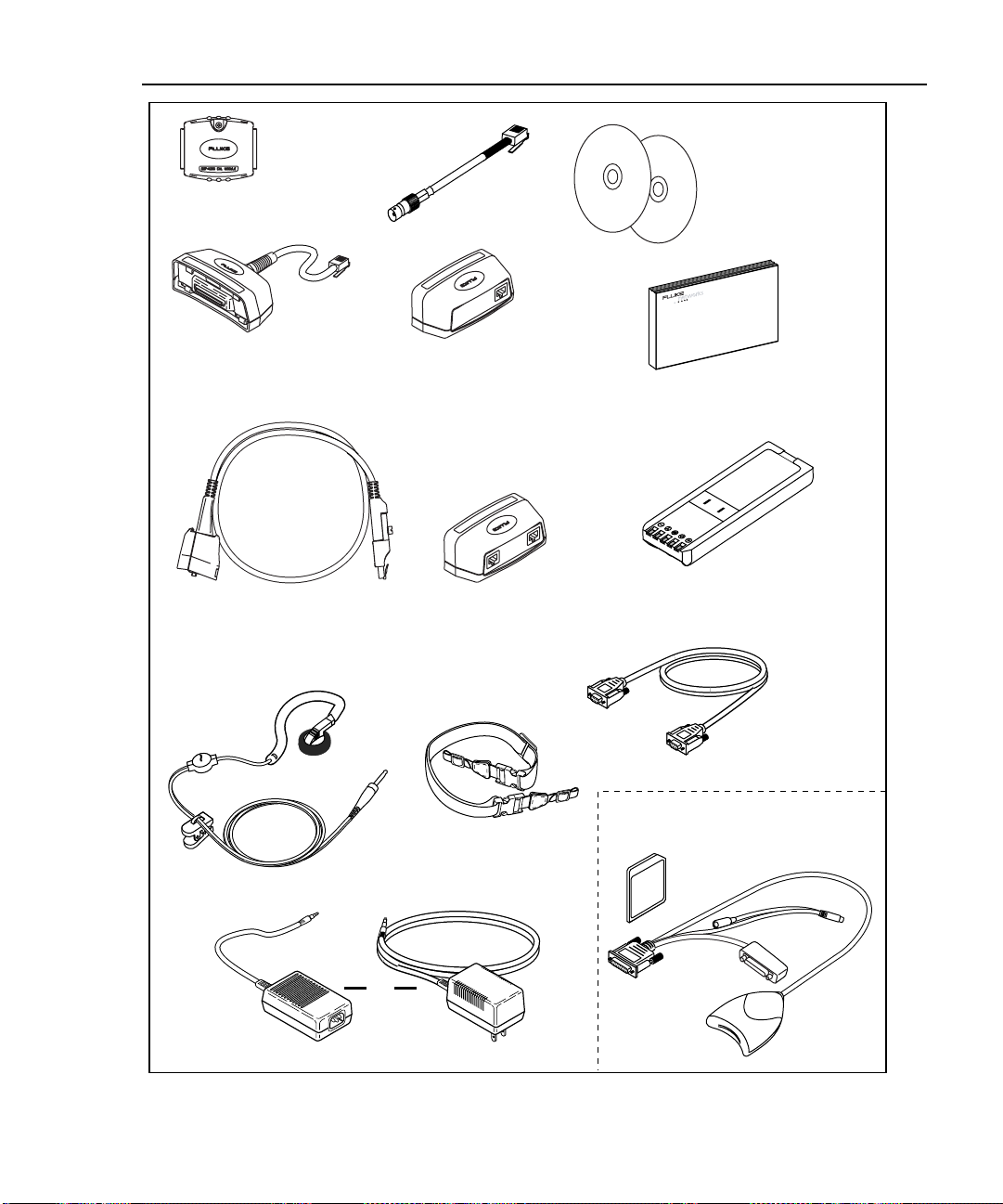
Standard Accessories
A DSP-4000 Series test tool comes with the following accessories, which are
shown in Figure 1-1. If the test tool is damaged or something is missing, contact
the place of purchase immediately.
• 1 DSP-4000SR, DSP-4100SR, or DSP-4300SR remote unit (not shown)
• The following link interface adapters:
◊ With the DSP-4000 and DSP-4100: 2 DSP-LIA011 Basic Link Adapters
for Cat 5E and 2 DSP-LIA012 Channel Adapters for Cat 6
◊ With the DSP-4000PL: 2 DSP-LIA101 Permanent Link Adapters for Cat 6
and 2 DSP-LIA012 Channel Adapters for Cat 6
◊ With the DSP-4300: 2 DSP-LIA101 Permanent Link Adapters for Cat 6,
1 DSP-LIA012 Channel Adapter for Cat 6, and 1 DSP-LIA013
Channel/Traffic Adapter for Cat 6
• 2 AC adapter/chargers 120 V (US only) or universal adapter/chargers and line
cords (outside North America)
• 1 Memory card reader (DSP-4100, DSP-4300)
• 1 16 MB memory card (DSP-4100, DSP-4300)
• 1 Memory card carrying case (DSP-4100, DSP-4300; not shown)
• 2 NiMH battery packs (installed)
• 2 Headsets
• 1 DSP-4000 Calibration Module
• 1 RJ45 to BNC adapter
• 1 PC serial interface (EIA-232C) cable
• 2 Carrying straps
• 1 CableManager CD
• 1 DSP-4000 Series Manual CD (includes complete users manual)
• 1 DSP-4000 Series Getting Started Guide
• 1 Warranty registration card (not shown)
• 1 Soft carrying case (not shown)
If you purchased optional Fiber Test Adapters, refer to the Fiber Test Adapter
users manual for a list of fiber accessories.
1-4
Page 17
Introduction
Standard Accessorie s
1
DSP-4000 Calibration
Module
DSP-LIA011
(2 with DSP-4000
and DSP-4100)
DSP-LIA101
(2 with DSP-4000PL
and DSP-4300)
RJ45 to BNC
Adapter
DSP-LIA012
(2 with DSP-4000,
DSP-4000PL
and DSP-4100;
1 with DSP-4300)
DSP-LIA013
(1 with DSP-4300)
DSP-4000 Series
Manual CD
CableManager
Software CD
TM
DSP-4000 Series
Getting Started Guide
Nickel-Metal Hydride
(2) Battery Pack
Headsets (2)
Straps (2)
or
AC Adapter/Charger
Figure 1-1. Standard Accessories
RS-232 Cable
DSP-4100/DSP-4300
Memory Card
Memory Card
Reader
oy01f.eps
1-5
Page 18

DSP-4000 Series
Users Manual
Using This Manual
Before using the test tool, carefully read "Safety and
Operational Information" at the beginning of Chapter 2.
Except where noted, the information in this manual applies to all DSP-4000 Series
test tools.
If you are familiar with the general features, functions, and operation of LAN
cable testers and want to start testing cables immediately, proceed as follows:
1. Read “Quick Start” in Chapter 2 to prepare the test tool for operation, access
the test tool’s functions, and run an Autotest.
2. Refer to the test and setup features listed under “Rotary Switch” in Chapter 2
to locate functions in the test tool’s menu structure.
3. Refer to the Glossary in the Appendix to find definitions for unfamiliar terms.
If you have never used a LAN cable tester, but want to start testing cables
immediately and learn as you work, proceed as follows:
1. Read “Quick Start” in Chapter 2 to prepare the test tool for operation, access
the test tool’s functions, and run an Autotest.
Warning
1-6
2. Refer to the Glossary in the Appendix to find definitions for unfamiliar terms.
3. Refer to the test and setup features listed under “Rotary Switch” in Chapter 2
to locate functions in the test tool’s menu structure.
4. Refer to Chapter 3, “Autotest,” to find more detailed information about cable
tests and test results.
5. Read Chapter 4, “Running Individual Tests,” to learn how to run individual
tests and monitor network traffic and impulse noise.
6. Read Chapter 7, “Basic Cable Testing,” to add to your cable testing and
troubleshooting knowledge.
Page 19

Introduction
Using This Manual
If you have never used a LAN cable tester and want to learn about cable testing
and troubleshooting before you use the test tool, proceed as follows:
1. Read Chapter 7, “Basic Cable Testing,” to learn the basics of LAN cable
characteristics, testing, and interpreting test results.
2. Read Chapter 2, “Getting Started”, to learn about the test tool’s features and
how to prepare the test tool for use.
3. Read Chapter 3, “Autotest,” to learn how to run the most commonly used
cable test and interpret the test results.
4. Read Chapter 4, “Running Individual Tests,” to learn how to run individual
tests and monitor impulse noise.
5. Refer to the test and setup features listed under “Rotary Switch” in Chapter 2
to locate functions in the test tool’s menu structure.
6. Refer to the Glossary in the Appendix to find definitions for unfamiliar terms.
For information on testing fiber cabling, refer to the users manual for your Fiber
Test Adapter.
1
1-7
Page 20

DSP-4000 Series
Users Manual
1-8
Page 21
Chapter 2
Getting Started
Chapter 2 provides the following information:
• Safety and cautions to observe when using the test tool.
• Instructions for getting started quickly with the test tool.
• Detailed information on the test tool’s features.
• Detailed instructions on configuring the test tool.
Read First: Safety and Operational Information
The international electrical symbols used on the instrument or in this manual are
described in Table 2-1. Certification symbols are described in "Specifications" in
Chapter 8.
Table 2-1. International Electrical Symbols
Warning: Risk of electric shock.
Warning or Caution: Risk of damage or destruction to equipment or software. See
explanations in the manual.
Equipment is protected by double insulation or reinforced insulation to protect the user
against electric shock.
Do not connect this terminal to public communications networks, such as telephone
systems.
2-1
Page 22

DSP-4000 Series
Users Manual
Warning
To avoid possible fire, electric shock, personal injury, or
damage to the test tool
• If this product is used in a manner not specified by the
manufacturer, the protection provided by the product
may be impaired.
• Use only the ac adapter/charger provided with the test
tool (PN 106200 or 944223) to charge the battery or
power the test tool.
• Never connect the test tool to any telephony inputs,
systems, or equipment, including ISDN. Doing so is a
misapplication of this product, which can result in
damage to the test tool and create a potential shock
hazard to the user.
• Never connect the CABLE TEST input to any LAN
inputs, systems, or equipment. Doing so is a
misapplication of this product, which can result in
damage to the test tool and create a potential shock
hazard to the user.
• Always turn on the test tool before connecting it to a
cable. Turning the test tool on activates the tool’s
input protection circuitry.
• When servicing the test tool, use only specified
replacement parts.
• Do not use the test tool if it operates abnormally.
Protection may be impaired.
• Do not use the test tool if it is damaged. Inspect the
test tool before use.
2-2
Page 23

Getting Started
Read First: Safety and Operational Information
Caution
To avoid disrupting network operation and to ensure
maximum accuracy of test results
• Except when monitoring network activity, never
connect the test tool to an active network. Doing so
may disrupt network operation.
• Never attempt to insert any connector other than an
RJ45 connector into the RJ45 jack. Inserting other
connectors, such as RJ11 (telephone) connectors, can
permanently damage the jack.
• Never attempt to send data from a PC to the test tool
while running a cable test. Doing so might cause
erroneous test results.
• Never operate portable transmitting devices during a
cable test. Doing so might cause erroneous test
results.
• When using the channel/traffic link interface adapter
(DSP-LIA013), never run tests with cables connected
to both the cable jack and the monitor jack. Doing so
might cause erroneous test results.
2
• To ensure maximum accuracy of test results, perform
the self-calibration procedure as described in
“Calibrating the Test Tool” in Chapter 6 every 30 days.
• To avoid false test results, recharge the battery as
soon as the low battery message appears.
• If your test tool includes the DSP-LIA101 Permanent
Link Adapters, see “Permanent Link Interface
Adapters” later in this chapter for important handling
information.
2-3
Page 24
DSP-4000 Series
Users Manual
Quick Start
This section is for users who want to start using the test tool immediately with
minimal instruction. For suggestions on additional reading that may be helpful to
you, see “Using this Manual” in Chapter 1. To get started with the optional Fiber
Test Adapters, refer to the Fiber Test Adapter users manual.
New features may be available with software upgrades. Visit the
Fluke Networks website at www.flukenetworks.com or contact your
Fluke Networks representative for information on upgrades.
Powering the Test Tool
Before powering the test tool or remote with the NiMH battery pack, charge the
battery for about 3 hours. To charge the battery, connect the ac adapter/charger to
the test tool or remote and to ac line power. You can operate the unit on ac power
while the battery charges. A fully-charged battery typically lasts at least 8 hours.
See “Battery Status” later in this chapter for information on battery status
messages.
The ac adapter/charger will not power the test tool when the battery
pack is removed.
Note
Note
Using the Menus
Key Function
U D L R Allow up, down, left, and right movement on the display.
E Selects the highlighted item.
T Starts the highlighted test.
e Exits the current screen.
!@
#$
2-4
The test tool’s setup configuration, test selections, and test results are presented in
a menu system. Table 2-2 shows the keys used to select items and move between
screens in the menu system.
Table 2-2. Key Functions for the Menu System
Softkeys select the function displayed on the screen area above the key.
Softkey functions depend on the screen displayed.
Page 25

Using the Link Interface Adapters
The link interface adapters provide the correct connectors and interface circuitry
for testing different types of LAN cable. The adapters also allow for upgrades
when new types of cable are developed. See “Link Interface Adapter Features” in
this chapter for more details.
If your test tool includes the DSP-LIA101 Permanent Link Adapters, see
“Permanent Link Interface Adapters” in this chapter for important handling
information.
Optional link interface adapters that provide additional functions are available
from your Fluke Networks dealer. Visit the Fluke Networks website at
www.flukenetworks.com for the most recent information on optional adapters.
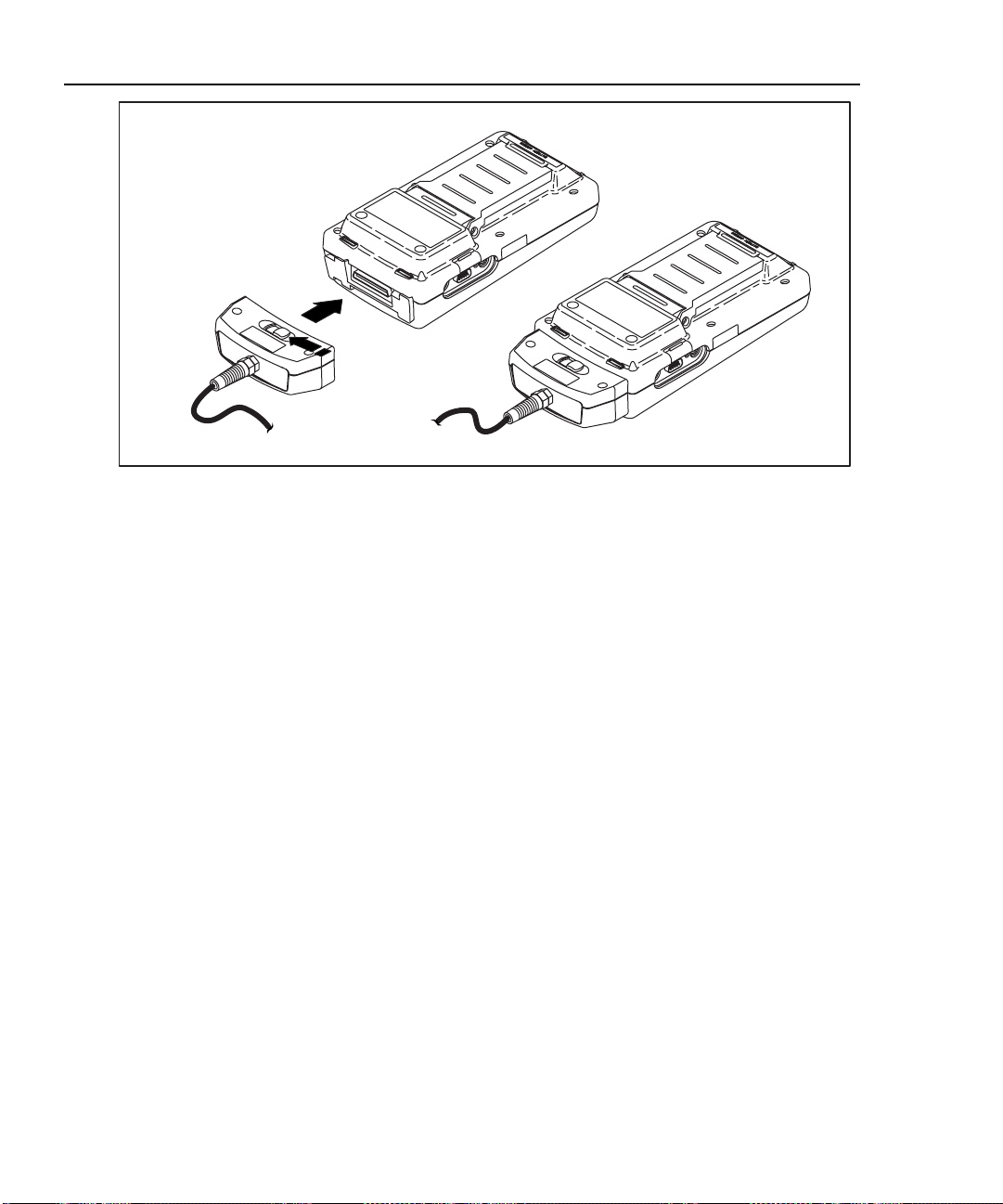
Figure 2-1 shows how to attach a link interface adapter. Self-calibration is not
required when you change adapters. The test tool displays a message if you try to
run a test that is not supported by the attached link interface adapter. Refer to
Appendix A for a list of tests supported by the standard link interface adapters.
The LIA Status selection on the SPECIAL FUNCTIONS menu reports the type of
link interface adapter attached to the main and remote units. The status display
also shows how many Autotests have been run with each adapter.
Getting Started
Quick Start
2
2-5
Page 26
DSP-4000 Series
Users Manual
Figure 2-1. Attaching a Link Interface Adapter
Formatting the Memory Card (DSP-4100/4300)
Autotest results you save on a DSP-4100 or DSP-4300 test tool are stored on a
removable memory card. One 16 MB card is included with the test tool.
Compatible cards of different capacities can also be used in the test tool. Figure
2-2 shows how to insert and remove the card. You do not need to turn the test tool
off before inserting or removing the card.
Before you store test results, the card must be formatted as follows:
1. Insert the card into the test tool as shown in Figure 2-2.
2. Turn the rotary switch to SPECIAL FUNCTIONS. Use D to select
Memory Card Configuration; then press E.
3. Press $ Format; then press # Yes to begin formatting.
For instructions on using the memory card reader and transferring Autotest results
to a PC, see “Getting Started” under Help on the CableManager toolbar.
oy72f.eps
2-6
Page 27
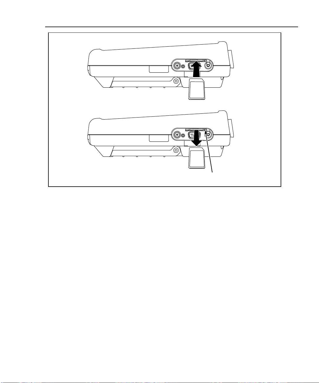
Inserting the card
Removing the card
Push button to eject card
Getting Started
Quick Start
2
Figure 2-2. Inserting and Removing the Memory card
oy79f.eps
To see the status of the memory card, press the Memory softkey that appears on
several of the Autotest displays or select Memory Card Configuration
in the SPECIAL FUNCTIONS mode.
Caution
The test tool may not be able to read or store test results
on a memory card that contains other types of data (such
as music files).
2-7
Page 28
DSP-4000 Series
Users Manual
Quick Configuration
The settings listed in Table 2-3 affect either the display format or the accuracy of
your test results. Following the table are instructions for changing the settings. For
a complete list of the test tool’s adjustable settings, refer to the later section
“Setup.”
SETUP Setting Description
Table 2-3. Quick Configuration Settings
Test Standard
and Cable Type
Report
Identification
Auto Increment
(cable ID setup)
Store Plot Data
(DSP-4100/4300)
Length Units Select meters or feet as the unit for length measurements.
Numeric Format Select a format (0.00 or 0,00) for display of decimal fractions.
Display and
Report Language
Power Line Noise
Filter Frequency
Select the test standard and cable type you are using. Fiber optic cable
testing requires a Fluke Networks DSP-FTA Fiber Test Adapter or a
Fluke Networks DSP-FOM (Fiber Optic Meter; comes with the DSP-FTK).
Enter your company’s name, operators’ names, and site names. These
names appear in the Autotest reports you save.
Enabling this setting causes the last character of the cable ID to
increment each time you save an Autotest. The Sequence selection lets
you define a range of cable IDs by entering a start and end ID. On a
DSP-4300, the Cable ID List selection lets you select a list of IDs that was
created and saved on a memory card with CableManager software.
Enable this setting to store plot data (from tests such as attenuation,
return loss, and NEXT) with Autotest results saved on a DSP-4100 or
DSP-4300 test tool.
Select English, German, French, Spanish, Italian, Portuguese, or
Japanese.
Select the frequency of the ac power in your area. The test tool filters out
50 Hz or 60 Hz noise from measurements.
2-8
Page 29
To change any of the settings shown in Table 2-3, proceed as follows:
1. Turn the rotary switch to SETUP.
2. If the setting you want to change is not on the first Setup screen, press
$ Page Down to see additional Setup screens.
3. Use D U to highlight the setting you want to change.
4. Press ! Choice.
5. Use D U to highlight the setting you want.
6. Press E to store the highlighted setting.
7. Repeat steps 2 through 6 to change additional settings.
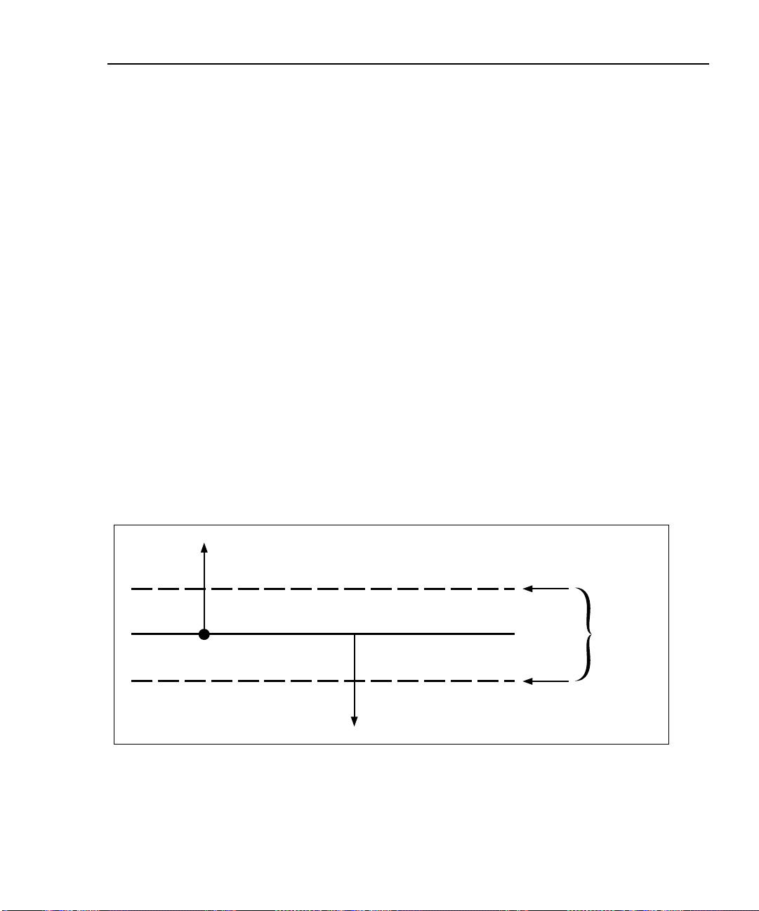
Results within Accuracy Range
An asterisk following a test result value indicates that the value is within the test
tool’s range of accuracy, as shown in Figure 2-3. All tests except the wire map test
may produce results with an asterisk if required by the selected test standard. If
you want the asterisk to appear on the overall pass/fail test result as well as the
individual test result, enable “Top Level Pass* Indication” in SETUP.
If a “pass” result is marked with an asterisk, look for ways to improve the cabling
installation to eliminate the marginal performance. A “fail” result marked with an
asterisk should be considered a failure.
Getting Started
Quick Start
2
The asterisk appears on displayed, uploaded, and printed test results.
Pass
*
Pass Region
Limit
*
Fail Region
Fail
Figure 2-3. The Asterisk and Test Tool Accuracy
Accuracy
Range of
Test Tool
oy02f.eps
2-9
Page 30

DSP-4000 Series
Users Manual
Autotest on Twisted Pair Cabling
Autotest performs all of the tests necessary to determine if the cabling you are
testing meets the test standards specified for your LAN installation.
The following tests apply to twisted pair cabling:
• Headroom report (The worst-case margin for a parameter determined by the
selected standard. This may be NEXT, ACR, PSNEXT, or another
measurement.)
• Wire Map
• Resistance
• Length
• Propagation Delay
• Delay Skew
• Impedance
• NEXT and ELFEXT (Near-End and Equal Level Far-End Crosstalk)
• Attenuation
• ACR (Attenuation to Crosstalk Ratio)
• RL (Return Loss)
• PSNEXT (Power Sum NEXT)
• PSELFEXT (Power Sum Equal Level Far-End Crosstalk)
• PSACR (Power Sum ACR)
When you start an Autotest, the test tool displays a message if the attached link
interface adapter does not support the selected test standard.
2-10
To Autotest twisted pair cabling, refer to Figures 2-4 through 2-6 and proceed as
follows:
Note
If the calibration message appears after you start the Autotest, refer
to “Calibrating the Test Tool” in Chapter 6 for complete calibration
instructions.
Page 31

1. Attach the appropriate link interface adapters to the main and remote units.
Refer to the table in the Appendix.
2. Turn the remote’s rotary switch to ON.
3. Connect the remote to the far end of the cable link. For channel testing,
connect using the network equipment patch cord.
4. Turn the rotary switch on the main unit to AUTOTEST.
5. Verify that the settings displayed are correct. You can change these settings in
the SETUP mode.
6. Connect the test tool to the near end of the cable link. For channel testing,
connect using the network equipment patch cord.
7. Press T to start the Autotest.
Saving Test Reports
When an Autotest is complete, you can save the results by pressing S. Use
the alphanumeric display to enter a cable identification for the report; then press
S again. See Chapter 3 for details.
Getting Started
Quick Start
2
To create lists of cable IDs, see “Setting Up Cable IDs” in this chapter. You can
view and delete saved Autotest reports in the SPECIAL FUNCTIONS mode.
See “Getting Started” under Help on the CableManager toolbar for details on
uploading reports to a PC.
2-11
Page 32

DSP-4000 Series
Users Manual
Telecommunications
closet
Horizontal
cross-connect
Hub
Test equipment
cord
Horizontal
cabling
Transition
outlet
Work Area
Wall
outlet
PC
Test equipment
cord
Basic Link LIA
2-12
Basic Link LIA
TALK
Smart
Remote
Test Tool
oy68f.eps
Figure 2-4. Typical Test Connections for a Basic Link
Page 33

Getting Started
Quick Start
2
Telecommunications
closet
Horizontal
cross-connect
Hub
Patch cord
from hub
Horizontal
cabling
Transition
outlet
Work Area
Wall
outlet
PC
Patch cord
from PC
Channel LIA
Channel LIA
Test Tool
Figure 2-5. Typical Test Connections for a Channel
TALK
Smart
Remote
oy03f.eps
2-13
Page 34

DSP-4000 Series
Users Manual
Telecommunications
Work Area
closet
Work Area
Consolidation
point (optional)
Patch panel
Permanent
link adapter
Horizontal
cabling
Telecommunications
outlet
Test tool
Remote
Figure 2-6. Typical Test Connections for a Permanent Link
PC
Permanent
link adapter
TALK
oy84f.eps
2-14
Page 35

Using the Talk Mode
The Talk mode allows two-way voice communication over twisted pair or fiber
cable (Fiber Test Adapters are required for fiber cable). Two-way communication
over twisted pair cable requires two good wire pairs.
The Talk mode is disabled during cable tests. The DSP-LIA013
supports the Talk Mode only through the CABLE TEST jack.
Use the Talk mode as follows:
1. Connect the main and remote units to the cable under test.
2. Plug the headsets into the headset jacks on the main and remote units.
3. Press V on either the main or rem ote uni t; then spe ak into the head set’s
microphone. To adjust the volume at the main unit, use U or D. To adjust
the volume at the remote, use V to cycle through the volume settings.
4. To exit the Talk mode, press e or turn the rotary switch to a new posi tio n.
The Talk mode turns off automatically when you start a cable test.
Note
Getting Started
Quick Start
2
2-15
Page 36

DSP-4000 Series
Users Manual
Autotest on Coaxial Cabling
The following tests are run during an Autotest on coaxial cabling:
• Impedance
• Resistance
• Length
• Anomaly detection (Results shown only if anomalies are detected.)
To run an Autotest on coaxial cabling, refer to Figure 2-7 and proceed as follows:
1. Turn off any PC nodes connected to the cabling you are testing.
2. If you want the Autotest to report cable length, remove the terminator from the
far end of the cabling.
3. Attach any channel link interface adapter to the main unit.
4. Turn the rotary switch to AUTOTEST.
5. Verify that the test standard and cable type displayed are correct. You can
change these settings in the SETUP mode.
6. Remove the terminator from the near end of the coaxial cabling. Use the RJ45
to BNC adapter to connect the cable to the test tool.
2-16
7. Press T to start the Autotest.
Page 37

PC
Getting Started
Quick Start
2
PC
12345678
PC
12345678
12345678
For Length Test,
remove far-end
Terminator
Channel LIA
BNC “T”
Connector
CABLE ANALYZER
DSP-4000
1
23
4
TALK
SAVE
ENTER
TEST
MONITOR
SINGLE
SETUP
TEST
PRINT
SPECIAL
FUNCTIONS
Test Tool
EXIT
FAULT
INFO
AUTO
TEST
OFF
Figure 2-7. Autotest Connections for Coaxial Cabling
oy04f.epc
2-17
Page 38

DSP-4000 Series
Users Manual
Main Unit Features
Figure 2-8 shows the features on the main unit and Table 2-4 explains their
functions.
DSP-4100/4300 Side Plate
17
18
12
DSP-4000 Side Plate
6
14
13
7
1
23
5
4
3
2
EXIT
FAULT
INFO
OFF
AUTO
TEST
TEST
SINGLE
TEST
ENTER
MONITOR
SETUP
SAVE
4
TALK
PRINT
SPECIAL
FUNCTIONS
8
9
10
11
15
16
1
oy05f.eps
Figure 2-8. Main Unit Features
2-18
Page 39

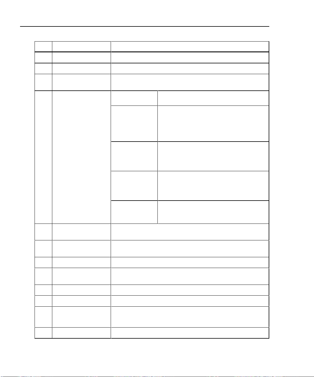
Table 2-4. Main Unit Features
Item Feature Description
A
B
C
D
E
F
G
H
I
J
K
L
M
N
Rotary Switch Selects the test tool’s modes.
T
F
e
!@
#$
Display A LCD display with backlight and adjustable contrast.
L R U D
C
V
S
E
LIA connector and
latch
RS-232C serial
port
2.5 mm phone jack Connection for the headset supplied with the test tool.
Starts the highlighted test or restarts the test last run.
Automatically provides more specific information on the cause
of an Autotest failure.
Exits the current screen without saving any changes you made.
Provide functions related to the concurrent display. Softkey
functions are shown in the display area above the keys.
Allow left, right, up, and down movement on the display.
Increase or decrease the numerical values of user-definable
parameters.
Controls the display backlight. Pressing for 1 second allows
adjustment of the display contrast. Reactivates the test tool
when the tool is in power down mode.
Lets you use the headset for two-way voice communication
over twisted pair or fiber cable.
Saves Autotest results and parameter changes in memory.
Selects the highlighted item from a menu.
Connector and latch for the link interface adapters (LIAs).
A 9-pin connector for interfacing with a printer or host computer
via a standard IBM-AT EIA RS-232C serial cable.
Getting Started
Main Unit Features
2
2-19
Page 40

DSP-4000 Series
Users Manual
Item Feature Description
Table 2-4. Main Unit Features (cont.)
O
P
Q
R
AC power indicator
AC adapter/ charger jack Connection for the ac adapter/charger supplied with
Eject button (DSP-4100/4300) Button for ejecting the memory card.
Memory card slot
(DSP-4100/4300)
LED off,
unit turned off
LED off,
unit turned on
LED flashing red Fast charge pending.
LED steady red
LED steady
green
the test tool.
Slot for the memory card used for saving Autotest
results on a DSP-4100 or DSP-4300 test tool.
Battery is not charging.
The charger is not plugged in.
Battery is not charging.
The charger is not plugged in
or the test tool is running a
test. When the test is
finished, charging resumes
unless the battery is already
charged (>80%).
Charging is beginning. This
state may last for several
minutes until fast charging
begins.
Fast charge.
The unit stays in fast charge
mode for up to 4 hours, or
until either the battery is fully
charged or a test is initiated.
Charge complete.
Fast charge is complete. The
unit enters trickle charge
mode.
2-20
Page 41

Remote Features
Figure 2-9 shows the features on the remote unit, and Table 2-5 explains their
functions.
2
Getting Started
Remote Features
5
2
1
3
PASS
TESTING
FAIL
TALKING
LOW BATTERY
6
7
8
9
10
4
TALK
11
12
ON
OFF
oy06f.eps
Figure 2-9. Remote Features
2-21
Page 42
DSP-4000 Series
Users Manual
Table 2-5. Remote Connectors and Features
Item Feature Description
1
2
3
4
RS-232C serial port A DB9P connector for loading software updates.
2.5 mm phone jack Connection for the headset supplied with the test tool.
AC adapter/
charger jack
AC power indicator
Connection for the ac adapter/charger supplied with the test
tool.
LED off,
unit turned off
LED off,
unit turned on
LED flashing
red
LED steady red Fast charge.
LED steady
green
Battery is not charging.
The charger is not plugged in.
Battery is not charging.
The charger is not plugged in or the test
tool is running a test. When the test is
finished, charging resumes unless the
battery is already charged (>80%).
Fast charge pending.
Charging is beginning. This state may last
for several minutes until fast charging
begins.
The unit stays in fast charge mode for up to
4 hours, or until either the battery is fully
charged or a test is initiated.
Charge complete.
Fast charge is complete. The unit enters
trickle charge mode.
2-22
5
6
7
8
9
0
f
g
LIA connector and
latch
Pass LED A green LED that turns on at the end of a test if no faults were
Test LED A yellow LED that turns on when a test is in progress.
Fail LED A red LED that turns on at the end of a test if one or more faults
Talking LED A LED that turns on when the Talk mode is active.
Low-battery LED A LED that turns on when the remote battery voltage is low.
X
TALK
Rotary switch On/off switch for remote.
Connector and latch for attaching link interface adapters.
detected.
were detected.
Lets you use the headset for two-way voice communication
over twisted pair or fiber cable. When the Talk mode is active,
this button controls the headset volume.
Page 43

Link Interface Adapter Features
Getting Started
Link In terface Adapter Feat ures
2
2
DSP-LIA011
DSP-LIA101
1 DSP-LIA011
cable and plug
1
DSP-LIA012
4
DSP-LIA013
Shielded Cat 5E twisted pair cable with a shielded Cat 5E RJ45
plug for testing basic link installations.
2 DSP-LIA012 jack Shielded RJ45 jack for testing channel installations.
3
Latch and 60-pin
connector
Latch and connector for attaching the LIA to a DSP-4000 Series
test tool.
3
5
6
oy71f.ep
4 DSP-LIA101
cable with
personality
module
(DSP-4000PL/
DSP-4300)
5 DSP-LIA013
CABLE jack
6 DSP-LIA013
MONITOR jack
One meter of proprietary, high-performance cable terminated with a
removable personality module. The personality module ensures
electrical compatibility with a particular manufacturer’s jack. See the
next section for additional information.
The standard module is designed for use with various jacks. Refer to
the PMxx module list included for applications of available modules.
Shielded RJ45 jack for testing channel installations.
Shielded RJ45 jack for traffic tests, the hub port capabilities test, and
the hub port locator.
Figure 2-10. Link Interface Adapter Features
2-23
Page 44

DSP-4000 Series
Users Manual
Permanent Link Interface Adapters (DSP-4000PL/4300)
Caution
To avoid damaging the adapter and to ensure maximum
accuracy of test results, never pinch, kink, or crush the
adapter’s cable. Never use the cable as a handle to pick
up the DSP test tool. Follow the handling guidelines given
in Figure 2-11.
For the best accuracy, keep the adapter’s cable as straight
as possible during testing.
To avoid latent or immediate damage due to electrostatic
discharge:
• Before handling a module or an adapter with no
module attached, ground yourself when possible by
touching a grounded, conductive surface.
• Always remove the adapter from the DSP test tool
before changing the personality module.
• Always keep a personality module attached to the
adapter cable.
2-24
• Always store the personality module in its original,
static protection bag when not in use.
4" (10 cm)
minimum bend
360˚ twist maximum
Storage
oy85f.eps
Figure 2-11. Permanent Link Adapter Handling Guidelines
Page 45

Link In terface Adapter Feat ures
Changing the Personality Module (DSP-4000PL/4300)
You can change the personality module to make the adapter compatible with a
certain manufacturer’s jack. Visit the Fluke Networks website for the most recent
list of available personality modules.
Replace the module as follows (refer to Figure 2-12):
1. Ground yourself by touching a grounded, conductive surface.
2. Remove the link interface adapter from the DSP test tool.
3. Use your fingers to unscrew the screw on the personality module. If necessary,
you can use a flat-blade screwdriver to loosen the screw.
4. Remove the module; then store it in its original, static protection bag.
5. Put the new module in place and tighten the screw with your fingers.
Caution
Tighten the screw snugly with your fingers only. Do not
overtighten. Doing so can damage the module or the end
of the cable.
Getting Started
2
Personality
module
Figure 2-12. Changing the Personality Module
Static sensitive
device
oy86f.eps
2-25
Page 46

DSP-4000 Series
Users Manual
Strap and Bail
The test tool and the remote have a strap and a bail. Figure 2-13 shows how to
attach the strap and open the bail.
Figure 2-13. Attaching the Strap and Opening the Bail
Rotary Switch
The following paragraphs summarize the modes you can select with the rotary switch on
the main unit.
Off
Turns the test tool off. Setup information and test results saved via the S key
are stored in nonvolatile memory.
2-26
oy07f.eps
Page 47

Autotest
Autotest is the most frequently used function in LAN cable testing. Autotest
performs all of the tests necessary to qualify the cabling you are testing. When the
Autotest is complete, the tests that were run are listed with the overall result for
each test. You can also view detailed results for each test. Resul ts from Autotests
can be saved for printing or transmission to a host computer.
The following tests apply to twisted pair cabling:
• Headroom: Reports the worst-case margin for a parameter determined by
• Wire Map: Tests for opens, shorts, crossed pairs, reversed wires, and split
• NEXT and ELFEXT: Tests twisted pair cabling for near-end crosstalk
• Length: Displays the length of twisted pairs in feet or meters.
• Propagation Delay: Measures the times taken for a signal to travel the length
• Delay Skew: Calculates the differences in propagation delays between the
• Impedance: Measures the im pedance of each cab le pair . I f impedance
Getting Started
Rotary Switch
Note
The tests run during an Autotest on twisted pair cabling depend on
the test standard selected. Tests not applicable to the selec ted tes t
standard are not run or displayed. For a list of the tests and limits
associated with common standards, see the document provided on
the Fluke Networks website at www.flukenetworks.com.
selected test standard. This may be NEXT, ACR, PSNEXT, or another
measurement.
pairs.
(NEXT) and equal level far-end crosstalk (ELFEXT).
of each cable pair.
cable pairs.
anomalies are detected, the test reports the largest anomaly detected on each
cable pair.
2
2-27
Page 48

DSP-4000 Series
Users Manual
• Attenuation: Measures the attenuation of each cable pair.
• DC Resistance: Measures the loop resistance of each cable pair.
• ACR: Calculates the ratio of attenuation to crosstalk for all combinations of
• RL (Return Loss): Measures signal loss due to signal reflections in the
• PSNEXT (Power Sum NEXT): For each cable pair, PSNEXT is calculated as
• PSELFEXT (Power Sum ELFEXT): For each cable pair, PSELFEXT is
• PSACR (Power Sum ACR): For each cable pair, PSACR is calculated using
The following tests apply to coaxial cabling:
• Impedance: Measures the impedance of the cable.
• Resistance: Measures the loop resistance of the cabling, shield, and
• Length: Measures the length of unterminated cables.
cable pairs.
cabling.
the sum of the NEXT from all other pairs.
calculated using the sum of the FEXT from the other pairs.
the sum of the NEXT from the other pairs.
terminator.
• Anomaly Detection: During a coaxial cable test, the test tool also detects and
Single Test
The SINGLE TEST mode provides access to the individual tests defined by the
selected test standard, except for the ACR test. This mode also lets you run the
HDTDR and HDTDX analyzer tests. A scanning function, which continuously
repeats the test, is available for the wire map, resistance, HDTDR, and HDTDX
analyzer tests. Single tests are useful for isolating cabling faults and quickly
checking repairs.
reports the position of the largest impedance anomaly (if any are present) on
the cable.
2-28
Page 49

Monitor
Setup
Getting Started
Rotary Switch
The MONITOR mode lets you continuously monitor impulse noise on twisted pair
network cabling. With the DSP-LIA013 link interface adapter, you can monitor
network activity on Ethernet systems. Network activity is monitored for collisions,
jabber, and percentage of system utilization. The traffic adapter also includes a hub
port locator, which helps you determine port connections at a hub, and a hub port
capabilities feature that determines the standards supported by a port.
Allows you to do the following:
• Select a test standard and cable type.
• Edit the report identification that appears on saved Autotests.
• Set up the tester to automatically generate cable IDs.
• On DSP-4100 and DSP-4300 test tools, you can set the test tool to save
attenuation, return loss, NEXT, and FEXT plots as part of Autotest reports
when those tests are required by the selected test standard.
• Set the backlight timer to turn off the backlight after a specified period of
inactivity.
2
• Set the power-down timer to switch the test tool to a low-power mode after a
specified period of inactivity.
• Select interface parameters for the serial port.
• Set the date and time.
• Select a format for the date and time.
• Select a unit for length measurements.
• Select a format for displaying decimal fractions.
• Select a language for the display and printed reports.
2-29
Page 50

DSP-4000 Series
Users Manual
• Select a frequency for the power line noise filter.
• Set the fault threshold for the impulse noise test.
• Enable or disable the test tool’s beeper.
• Modify test standards for custom test configurations.
• Select a remote end configuration when a Fiber Test Adapter is attached.
Allows you to send saved reports or report summaries to a serial printer. You can
print the results from previously stored Autotests. Also lets you edit the report
identification information and select a format for Autotest reports sent directly to a
printer.
Special Functions
Allows you to do the following:
• View or delete test reports saved in memory.
• Change the cable identification assigned to a saved Autotest report.
• Generate a tone to use with an inductive pickup device, such as the Fluke
Networks 140 A-Bug Tone Probe, to identify cabling runs.
2-30
• Determine the cable NVP to ensure maximum accuracy of length results.
• View the status of the NiMH battery in the main unit or remote.
• Check the status of the LIA attached to the main or remote unit.
• Perform a self-calibration on the test tool and remote.
• Run a self-test to verify proper operation of the test tool, link interface adapter,
and remote.
• On DSP-4100 and DSP-4300 test tools, you can view the status of the memory
card and format the card.
• View version information for the main and remote units.
Page 51

Turning On the Test Tool
To turn on the test tool, turn the rotary switch from OFF to any one of the
available modes. The power-up screen, which appears for about 3 seconds, shows
the software, hardware, and test standards versions for the main and remote units.
(The remote information is shown only if the remote is on and connected to the
main unit.) For a longer look at the power-up screen, hold down any key while
turning the test tool on. Or, select Version Information in the SPECIAL
FUNCTIONS mode.
During this time, the test tool also performs a self-test. If a fault is detected during
the self-test, the following message appears: INTERNAL FAULT
DETECTED. REFER TO MANUAL. For information, see “If the Test Tool
Fails” in Chapter 8.
Selecting a Language for Displays and Reports
The test tool displays results and prints reports in English, German, French,
Spanish, Italian, Japanese, and Portuguese.
The test tool displays a language selection screen if a language has not been
selected since the tool left the factory. Afterwards, you can change the language as
follows:
Getting Started
Turning On the Test Tool
2
1. Turn the rotary switch to SETUP.
2. Press $ Page Down to find the language selection.
3. Use D to highlight the currently selected language.
4. Press ! Choice.
5. Use D U to highlight the language you want.
6. Press E to accept the highlighted language. The test tool’s display now
appears in the selected language.
2-31
Page 52

DSP-4000 Series
Users Manual
Performing a Self-Test
The self-test verifies that the test tool, link interface adapters, and remote are
operating properly. To run the self-test, proceed as follows:
1. Turn the rotary switch to SPECIAL FUNCTIONS. Turn the remote on.
2. Use D to highlight Self Test.
3. Press E.
4. Use the DSP-4000 Calibration Module to connect the test tool to the rem ote.
5. Press T to start the self-test.
6. When the self-test is complete, you can either return to the main Special
Functions menu by pressing e or start a new operation by turning the rotary
switch to a new position.
If the self-test fails, refer to “If the Test Tool Fails” in Chapter 8.
Overvoltage Test
The test tool periodically checks for dc voltages on twisted pair cabling under test.
A dc voltage means that the test tool is connected to an active telephone cable or
other power source. If voltage is detected, the following message appears:
WARNING! EXCESSIVE VOLTAGE DETECTED AT INPUT.
UNPLUG CABLE NOW!. The remote unit beeps and all LEDs flash
continuously. Voltage on the cabling can damage the test tool or cause errors in
measurements. Voltage must be removed before you can run any tests.
2-32
Always turn on the test tool before connecting it to a cable. Turning the test tool on
activates the tool’s input protection circuitry.
Page 53

Noise Test
The test tool periodically checks for excessive electrical noise on the cabling under
test. Noise sources include nearby electrical equipment and transmitters and live
network transmissions on adjacent cables. If excessive noise is detected, the test
tool displays Noise Detected and automatically attempts to filter the noise
to meet published accuracy specifications. If the test tool cannot filter out all the
noise, and you save the test results, the test report will include the message
“WARNING Excessive noise detected. Measurement accuracy may be degraded”.
To stop the test and return to the first screen of the selected test mode, press e.
Configuring the Test Tool
The following sections provide more details about configuring your test tool. You
can configure the test tool in the SETUP mode, or you can use the CableManager
software provided to download SETUP selections from a PC to your test tool.
Controlling the Backlight
To toggle the backlight between its two levels of brightness, press C on the
keypad. You can set the backlight timer to automatically turn off the backlight
after a specified period of inactivity. You can also disable the backlight timer.
Getting Started
Configuring the Test Tool
2
To set the backlight timer or disable the timer, proceed as follows:
1. Turn the rotary switch to SETUP.
2. Press $ Page Down.
3. Use D to highlight the backlight time-out setting.
4. Press ! Choice.
5. Use D U to highlight the desired time-out period or the disable status.
6. Press E to accept the highlighted selection.
2-33
Page 54

DSP-4000 Series
Users Manual
When the backlight time-out is enabled, the backlight timer starts counting down
after all tests are complete or after the last key entry or movement of the rotary
switch. To restart the backlight timer while the backlight is on, press any key
(except the backlight key) or turn the rotary switch to a new mode.
Adjusting the Display Contrast
To adjust the display contrast, hold down C for 1 second or longer. The
following message appears: USE D U KEYS TO ADJUST CONTRAST.
Adjust the contrast to the desired level then press E to accept the new lev el.
The display contrast setting is saved in memory when you turn off the test tool.
Selecting a Power Line Filter Frequency
The test tool has a noise filter to keep ac noise (50 Hz or 60 Hz) from affecting
resistance measurements.
To set the frequency of the noise filter to the frequency of your ac power, proceed
as follows:
1. Turn the rotary switch to SETUP.
2. Press $ Page Down until you see the power line frequency setting.
3. Use D to highlight the power line frequency.
4. Press ! Choice.
5. Use D U to highlight the frequency you want.
6. Press E to accept the highlighted frequency.
2-34
Page 55

Selecting a Test Standard and Cable Type
The test standard and cable type you select determine which standards are used
and which tests are run during cable testing. The test tool is equipped with
information for all the common test standards and cable types.
Several of the test standards for twisted pair cable are defined for both a channel
and a permanent link configuration. Th e test limits for a channel are looser than
those for a perm anent link because the channel limits allow for the effects of two
connections at a horizontal cross-connect and a transition connector near the
telecommunications outlet in the work area. Figures 2-5 and 2-6 earlier in this
chapter show the connections involved in a permanent link and a channel. Chapter
7 further explains these connections.
Note
The test tool displays a message if you try to run a test not supported by the
attached link interface adapter.
To select a test standard and cable type, proceed as follows:
1. Turn the rotary switch to SETUP.
2. Press ! Choice. The standards list starts with the last five standards
used. Press $ Page Down to see more standards.
Getting Started
Configuring the Test Tool
2
3. Use D U to highlight the test standard you want.
4. Press E to accept the highlighted test standard. The test tool displays a
menu of the cable types valid for the selected test standard.
5. Use D U to select the cable type you want; then press E.
6. If you selected a shielded cable type, the next display lets you enable or
disable the shield test. Use D U to select the setting you want; then press
E.
You can test cables for NEXT, ELFEXT, PSNEXT, ELFEXT, attenuation, and
ACR, and PSACR up to 350 MHz. Test limits apply only up to the frequency
specified by the selected test standard.
2-35
Page 56

DSP-4000 Series
Users Manual
Editing the Report Identification
The report identification includes a custom header (your company name, for
example), an operator name, and a site name. These items appear on saved
Autotest reports. You can view and edit this information as follows:
1. Turn the rotary switch to SETUP.
2. Use D to highlight Edit under Report Identification; then
press E. The REPORT IDENTIFICATION display shows the information
that will appear on the Autotest reports you save.
3. Use D U to highlight the information you want to edit; then press E.
If you are editing an operator or site name, you can press @ New to add a
new name. The New softkey appears only if less than 20 names have been
entered. If 20 names have been entered, you must delete a name before adding
a new name.
To rename or delete an existing operator or site name, press ! Edit,
select the desired name; then press ! Rename or @ Delete.
Changes to names preceded by a "$" appear on printed test reports. You
cannot delete a name that is used on a saved report.
4. To add characters to the name, use the L R and D U keys to highlight
characters in the list, then press E.
2-36
To delete the character left of the cursor, press $Delete.
To edit characters in the middle of a name, use ! to move the cursor into
the name.
To move the cursor back to the right-most character, press ! until the
cursor wraps back to the right.
To increment or decrement an alphanumeric character anywhere in the cable
identification, use ! to highlight the desired character; then
press @INC or #DEC.
5. To store the name, press S.
Note
You can use CableManager software to download report identification
information from a PC to the test tool.
Page 57

Setting Up Cable IDs
The cable identification (cable ID) is the name you assign to the Autotest results
you save. You can create a cable ID each time you save an Autotest, or you can
use IDs generated as follows:
• The auto increment function generates IDs by incrementing the last
alphanumeric character in the cable ID.
• The auto sequence function generates IDs by incrementing characters through
a range of values defined by a start and end ID.
• On a DSP-4300 test tool, you can select IDs from lists downloaded to a
memory card. You can create and download the lists with CableManager
software.
Enabling the Auto Increment Function
The test tool’s auto increment function increments only the last alphanumeric
(letter or number) character of the cable identification name each time you save
Autotest results.
To enable or disable the auto increment function, proceed as follows:
1. Turn the rotary switch to SETUP.
Getting Started
Configuring the Test Tool
2
2. Use $ Page Down and D U (if necessary) to highlight the auto
increment setting; then press !Choice.
3. Use D U to highlight Enable; then press E.
The last character of the cable ID you enter when you save the next Autotest will
be incremented when you save subsequent Autotests.
2-37
Page 58

DSP-4000 Series
Users Manual
Determining a Range of Cable IDs for the Auto Sequence Function
Use the following guidelines when determining a range of cable IDs to use with
the auto sequence function.
• Cable IDs can contain a maximum of 18 letters, numbers, and special
characters (such as -, #, and spaces). Accented characters are not available.
• The types of characters used in each position must match between the range’s
start and end ID. For example, using the letter “O” as the third character in the
start ID and the number “0” as the third character in the end ID generates an
error message.
• The auto sequence function increments letters and numbers starting with the
farthest right character, then moving left. Special characters and matching
characters are not incremented. As an example, the following range of cable
IDs could be assigned for testing the cabling in 2 rooms where each room has
3 cable drops:
Start ID: ROOM A DROP#1
End ID: ROOM B DROP#3
The test tool would name the Autotest results in the following sequence:
ROOM A DROP#1
ROOM A DROP#2
ROOM A DROP#3
ROOM B DROP#1
ROOM B DROP#2
ROOM B DROP#3
2-38
If you try to save Autotest results after the last ID was used, the list shown after
you press S shows that all IDs are used by saved reports (used IDs are
preceded by a “$”). Use the Edit or New softkeys to create a new ID. See
Chapter 3 for more information.
Page 59

Enabling and Configuring the Auto Sequence Function
1. Determine the range of cable names you want to use for your Autotests. (Refer
to the previous section.)
2. Turn the rotary switch to SETUP.
3. Use D to highlight the auto inc rem ent sett ing ; then pres s ! Choice.
4. Use D U to highlight Sequence; then press ! Edit ID Seq.
5. Use ! to select the Start ID or End ID field for editing.
6. To add characters to the ID, use the L R U D keys to highlight a character in
the list, then press E.
Use @ Â and # ³ to move the cursor through the ID.
Use $ Delete to delete characters to the left of the cursor.
7. Press S when you are finished; then press E.
When necessary, you can edit the cable ID when you save an Autotest. See
Chapter 3 for information on saving Autotest results with the auto sequence
function enabled.
Selecting a List of Downloaded IDs (DSP-4300)
On a DSP-4300 test tool you can select cable IDs from lists created with
CableManager software and saved on a memory card. See “Getting Started” under
Help on the CableManager toolbar for details on creating ID lists.
Getting Started
Configuring the Test Tool
2
To select a downloaded list as the source for cable IDs, proceed as follows:
1. Put a memory card that holds one or more cable IDs lists into the test tool.
2. Turn the rotary switch to SETUP.
3. Use D U to highlight the auto increment setting; then press !Choice.
4. Use D U to highlight Cable ID List. To view the lists available on
the memory card, press ! Select ID List.
5. Use D U to highlight the list you want to use; then press E. The selected
list appears when you save an Autotest.
2-39
Page 60

DSP-4000 Series
Users Manual
Viewing the Cable ID Configuration and Memory Status
To see the cable ID configuration (if one is enabled), the number of Autotests
saved in memory, and the available memory, press the Memory softkey that
appears on several of the Autotest displays.
On a DSP-4100 or DSP-4300 you can see the memory card status by selecting
Memory Card Configuration in the SPECIAL FUNCTIONS mode.
Model DSP-4300 shows the status of the internal memory if no memory card is
present.
Storing Plot Data with Saved Autotest Results (DSP-4100/4300)
When STORE PLOT DATA is enabled, saved Autotest results include plot data
from tests such as the attenuation and NEXT tests. HDTDX and HDTDR plots are
also saved with the Autotest results. Saving the plot data lets you include plots on
test reports uploaded to a PC and printed with CableManager Software. The
DSP-4100 and DSP-4300 can save the results of at least 250 Autotests on a 16 MB
memory card when plot data is included. More results can be saved if plot data is
not included.
The DSP-4300 can save at least 250 Autotest results with plot data in internal
memory when a memory card is absent.
Enable or disable this setting as follows:
1. Turn the rotary switch to SETUP.
2. Use $ Page Down and D to find and highlight the store plot data
setting.
3. Press ! Choice.
4. Use D U to highlight the desired setting; then press E.
Selecting a Length Unit
The test tool displays length measurements in meters or feet.
To change the unit of measurement, proceed as follows:
1. Turn the rotary switch to SETUP.
2. Press $ Page Down until you see the length units setting.
3. Press ! Choice.
4. Use D U to highlight the desired unit.
5. Press E to accept the highlighted unit.
2-40
Page 61

Selecting a Numeric Format
The test tool displays decimal fractions with a decimal point separator (0.00) or a
comma separator (0,00).
To change the numeric format, proceed as follows:
1. Turn the rotary switch to SETUP.
2. Press $ Page Down until you see the numeric format setting.
3. Use D to highlight the numeric format.
4. Press ! Choice.
5. Use D U to highlight the desired format.
6. Press E to accept the highlighted format.
Setting the Date and Time
The test tool has a clock that records the date and time for saved test results.
To change the date or time or the format for the date or time, proceed as follows:
1. Turn the rotary switch to SETUP.
2. Press $ Page Down until you see the date and time settings.
Getting Started
Configuring the Test Tool
2
3. Use D to highlight the date or time parameter you want to change.
4. Press ! Choice. The display you see next depends on which parameter
you are changing.
If you are changing the date or time, use $ INC or # DEC to
increment or decrement the highlighted number. Use L R to move the
highlighted area from one number to another number.
If you are changing the date or time format, use D U to highlight the format
you want.
5. Press E to accept the highlighted date, time, or format.
2-41
Page 62

DSP-4000 Series
Users Manual
Setting the Power-Down Timer
To extend battery life, you can set the power-down timer to automatically switch
the test tool to a low-power mode after a selected period of inactivity. You can
also disable the power-down timer.
When the test tool switches to low-power mode, the display goes blank. To
reactivate the display, press C. The test tool turns it sel f off if not used fo r 30
minutes after power-down. When this happens, pressing C turns on the test tool
as though it were turned on with the rotary switch.
To set the power-down timer or enable/disable the timer, proceed as follows:
1. Turn the rotary switch to SETUP.
2. Press $ Page Down.
3. Use D to highlight the power-down timer status.
4. Press ! Choice.
5. Use D U to highlight the desired time-out period or the enable/disable status.
6. Press E to accept your selection.
Enabling or Disabling the Audible Tones
To enable or disable the test tool’s audible tones, proc eed as fol lows:
2-42
1. Turn the rotary switch to SETUP.
2. Press $ Page Down until you see the audible tone setting.
3. Use D to highlight the audible tone status.
4. Press ! Choice.
5. Use D U to highlight the desired enable or disable status.
6. Press E to accept your selection.
Page 63

Getting Started
Remote Lights, Messages, and Audible Tones
Remote Lights, Messages, and Audible Tones
The remote indicates various states by flashing light-emitting diodes (LEDs) and
emitting audible tones, as described in Table 2-6.
Table 2-6. Status Indications from the Remote
Status Remote Indications
Power on self-test passed. The unit beeps and all LEDs flash in sequence.
Power on self-test failed. The unit beeps and the fail LED flashes
continuously.
Main unit is running a test. Testing LED is on. Pass and fail LEDs flash as
tests pass or fail.
Previous test passed. Pass LED turns on for 15 seconds.
Previous test failed. Fail LED turns on for 15 seconds.
Talk mode is active. Talk LED turns on.
Battery voltage is low. The unit beeps and the low-battery LED flashes
continuously.
2
Battery voltage is too low to operate. The unit beeps and the low-battery LED is on
continuously.
Overvoltage condition detected on cable
under test.
The unit beeps and all LEDs flash continuously.
Caution
To avoid damage to the remote,
disconnect the cable immediately if
an overvoltage condition occurs.
Remote Communication Error
If the main unit detects a communication problem with the remote, the following
message appears on the main unit: REMOTE communication error.
This message means that the REMOTE data cannot be transmitted to the main
unit, usually because the cabling is defective. To verify proper remote operation,
run a self-test as described in the earlier section “Performing a Self-Test.”
2-43
Page 64

DSP-4000 Series
Users Manual
Battery Status
The test tool displays a message when its battery voltage or the remote battery
voltage is low. Table 2-7 shows the battery status messages and what you should
do if a battery message appears.
Note
To ensure continued operation while charging the battery, always
connect the ac adapter/charger when the message WARNING
RECHARGEABLE BATTERY VOLTAGE IS LOW appears.
Table 2-7. Battery Status Messages
Message Displayed What You Should Do
WARNING RECHARGEABLE BATTERY
VOLTAGE IS LOW.
RECHARGEABLE BATTERY VOLTAGE
IS TOO LOW TO OPERATE.
WARNING REMOTE BATTERY VOLTAGE
IS LOW.
WARNING REMOTE BATTERY
VOLTAGE IS TOO LOW TO OPERATE.
INTERNAL DATA STORAGE BATTERY
VOLTAGE IS LOW.
Battery Status Display
To see the charge level of the main unit’s NiMH battery, turn the rotary switch to
SPECIAL FUNCTIONS; then select Battery Status. To see the charge
level of the remote’s battery, connect the remote to the main unit; then use ! to
toggle the display.
Connect the ac adapter/charger.
Turn the test tool off and connect the ac
adapter/charger. If the tool does not operate
when you turn it on, turn it off again and allow
the battery to charge for about 30 minutes.
Connect the ac adapter/charger to the remote.
Connect the ac adapter/charger to the remote.
You might need to charge the battery for a short
time before the remote will operate.
Have the lithium battery replaced at a Fluke
Networks Service Center.
2-44
Page 65

Chapter 3 provides the following information:
• Instructions and test result descriptions for an Autotest on twisted pair cabling.
• Instructions and test result descriptions for an Autotest on coaxial cabling.
• Instructions for saving Autotest results.
Autotest Softkeys
New features may be available with software upgrades. Visit the
Fluke Networks website at www.flukenetworks.com or contact your
Fluke Networks representative for information on upgrades.
The following softkey functions are active on various Autotest screens.
! or @ View Result: ! shows the results of the last Autotest run.
@ shows detailed test results regarding the highlighted cable pair or pairs.
Chapter 3
Autotest
Note
# View Plot: Press to see a frequency response plot of the test results. Plot
data is available for the NEXT, ELFEXT, attenuation, ACR, RL, PSNEXT,
PSELFEXT, and PSACR tests.
@ Next Pair, @ Next Pairs: Press to see the detailed results or
the plot for the next cable pair or pairs tested.
$ or @ Memory: Press to see the number of Autotests stored and the
number of remaining memory location. If a cable ID list function, such as auto
sequence, is enabled, the display also shows the cable ID range, the total number
of IDs, and the number of IDs available.
3-1
Page 66

DSP-4000 Series
Users Manual
Autotest on Twisted Pair Cabling
The procedures for an Autotest on shielded and unshielded twisted pair cabling are
the same. The test tool tests shield continuity if shielded cable was selected and the
shield test enabled when the cable type was selected in SETUP.
To run the Autotest on twisted pair cabling, refer to Figures 3-1 through 3-3 and
proceed as follows:
1. Attach the appropriate link interface adapters to the main and remote units.
Refer to the table in the appendix.
2. Turn on the remote.
3. Connect the remote to the far end of the cable link. For channel testing,
connect using the network equipment patch cord.
4. Turn the rotary switch on the main unit to AUTOTEST.
5. Verify that the settings displayed are correct. You can change these settings in
the SETUP mode.
6. Connect the main unit to the near end of the cable link. For channel testing,
connect using the network equipment patch cord.
7. Press T to start the Autotest.
Notes
Pressing T when the previous Autotest was not saved causes
the test tool to display a warning message. In this case, you can
either save the results of the previous test by pressing S or
delete the results and start a new Autotest by pressing T.
If a remote is not connected, the test tool displays the message
SCANNING FOR SMART REMOTE and does not run the
Autotest until a remote is connected.
If the calibration message appears, refer to “Calibrating the Test
Tool” in Chapter 6 for complete calibration instructions.
3-2
Page 67

Autotest
Autotest on Twisted Pair Cabling
3
Telecommunications
closet
Horizontal
cross-connect
Hub
Test equipment
cord
Horizontal
cabling
Transition
outlet
Work Area
Wall
outlet
PC
Test equipment
cord
Basic Link LIA
Basic Link LIA
Test Tool
Figure 3-1. Typical Test Connections for a Basic Link
TALK
Smart
Remote
oy68f.eps
3-3
Page 68

DSP-4000 Series
Users Manual
Telecommunications
closet
Horizontal
cross-connect
Hub
Patch cord
from hub
Horizontal
cabling
Transition
outlet
Work Area
Wall
outlet
PC
Patch cord
from PC
Channel LIA
3-4
Channel LIA
TALK
Smart
Remote
Test Tool
oy03f.eps
Figure 3-2. Typical Test Connections for a Channel
Page 69

Telecommunications
closet
Patch panel
Autotest on Twisted Pair Cabling
Work Area
Work Area
Consolidation
point (optional)
Autotest
3
Permanent
link adapter
Horizontal
cabling
Test tool
Telecommunications
outlet
Remote
Figure 3-3. Typical Test Connections for a Permanent Link
PC
Permanent
link adapter
TALK
oy84f.eps
3-5
Page 70

DSP-4000 Series
Users Manual
Link Performance Grade Res ult (Headroom)
When an Autotest is complete, the display shows the overall result (pass or fail)
and the headroom value. Headroom is the smallest difference found between the
NEXT measurements and their limits. This number serves as a figure of merit that
reflects the overall performance of the link. Larger headroom values correspond to
better cabling performance.
To pass or fail cabling based on a minimum headroom value, enter the minimum
value as part of a custom test standard (see Chapter 6).
Worst Margin and Worst Value Results
Worst margin and worst value results are shown for frequency-dependent tests
such as NEXT, RL, ELFEXT, and ACR. Worst margin results are measurements
that came closest to the limit, or that exceeded the limit by the greatest amount.
Worst value results are the lowest measurements found, which may not necessarily
come closest to the limit.
Worst margin results for attenuation are not required by any test standard and are
not reported.
3-6
Page 71

Automatic Diagnos tics
If an Autotest fails, you can press F to see more specific information on the
cause of the failure. Figure 3-4 shows examples of automatic diagnostics displays
for a NEXT failure and an open pin failure.
The arrow in the diagram at the top of the display shows the location of the failure.
The bottom half of the display describes the failure and suggests ways to fix the
fault. When appropriate, softkeys let you see the plot or plots relevant to the
failure. If more than one fault was found, you can use the $ Next Fault
and # Prev Fault softkeys to scroll through the diagnostics displays.
See Chapter 4 for information on the HDTDR and HDTDX plots.
Autotest
Automatic Diagnost ics
3
Figure 3-4. Examples of Automatic Diagnostics Displays
oy09c.bmp
3-7
Page 72

DSP-4000 Series
Users Manual
Autotest Results for Twisted Pair Cabling
To see detailed results from a test, press ! View Result, use D U to
highlight the test on the main Autotest menu; then press E.
Note
The tests run during an Autotest on twisted pair cabling depend on
the test standard selected. Tests not applicable to the selec ted tes t
standard are not run or displayed. For a list of the tests and limits
associated with common test standards, visit the Fluke Networks
website at www.flukenetworks.com.
Wire Map Test
The wire map test tests and displays the wire connections between the near and far
ends of the cabling on all four pairs. Shield continuity is also tested if a shielded
cable was selected and the shield test enabled when the test standard was selected.
The pairs tested are those defined by the selected test standard. Table 3-1 shows
examples of wire map displays.
If the wire map test passes, the Autotest continues. You can view the wire map test
results when the Autotest is complete. If the wire map test fails, the Autotest halts
and the wire map screen appears with the word FAIL. You can then save the wire
map results by pressing
Test.
S. To continue the Autotest, press $ Continue
3-8
Table 3-1. Wire Map Displays
Wire Map
Condition
Correct wiring Cable wiring is correct. Shield (S) shown
Display Description
only if required by selected test
standard.
Page 73

Autotest
Autotest Results for Twisted Pair Cabling
Table 3-1. Wire Map Displays (continued)
Display
Wire Map
Condition
Crossed wires A wire in the 1,2 pair is crossed with
Reversed pairs Wires 1 and 2 are crossed.
Crossed pairs Pairs 1,2 and 3,6 are crossed.
Short Wires 1 and 3 are shorted. You can
Open Wire 1 is open near the main unit.
(only affected pairs shown) Description
a wire in the 3,6 pair. Wiring does not
form a recognizable circuit.
use the HDTDR test to locate the
short.
You can use the HDTDR test to
locate the open.
3
Split pair A wire in the 4,5 pair is twisted with a
wire in the 3,6 pair. You can use the
HDTDX analyzer to locate the split
pair.
3-9
Page 74

DSP-4000 Series
Users Manual
Resistance
The resistance test measures the dc loop resistance for each cable pair. The
resistance results screen displays the resistance, limit, and pass/fail result for each
cable pair. A PASS result means that the measured resistance is less than the
limit. A FAIL result means that the measured resistance exceeds the limit.
Length
The length test measures the length of each cable pair tested. The main Autotest
results screen shows the length of the cable pair having the shortest electrical
delay. The length results screen displays the length, limit, and pass/fail result for
each cable pair. Length is displayed in meters or feet. You can change the length
units in the SETUP mode, as described in “Selecting a Length Unit” in Chapter 2.
Notes
A 2 to 5 percent difference in measured length between twisted pairs
is typical. This difference is due to differences in the number of twists
in the cable pairs.
Differences between measured and actual values of cable length can
be caused by variations in the cable’s NVP value. NVP values can
vary among cable types, lots, and manufacturers. To ensure
maximum accuracy of length measurements, perform an NVP
calibration as described in Chapter 6.
3-10
A PASS result means that the measured length is within the specified limit for the
selected test standard. A FAIL result means that the measured length exceeds the
limit.
Page 75

Propagation Delay and Delay Skew
Propagation delays are the times taken in nanoseconds for a test pulse to travel the
length of each cable pair.
Delay skews are the differences in propagation delays between the shortest delay,
which is displayed as 0 ns, and the delays of the other cable pairs.
The propagation delay and delay skew results show a limit if the test is required by
the selected test standard. If the test is not required, the results always show
PASS.
Characteristic Impedance
The characteristic impedance test determines the approximate characteristic
impedance of each cable pair.
Impedance measurements require a cable at least 5 m (16 ft) long.
Cables shorter than this length will always pass the impedance test.
A PASS result means that the measured impedance is within the specified limit
for the selected test standard. A FAIL result means that the measured impedance
exceeds the specified limit, or an impedance anomaly is detected.
Autotest Results for Twisted Pair Cabling
Note
Autotest
3
A Warning result means that the measured impedance exceeds test limits, or an
anomaly is detected, but the characteristic impedance test is not required by the
selected test standard. The warning result causes a warning to appear as the test
summary result in printed repor ts.
The test tool reports an anomaly if 15 % or more of the test signal is reflected.
Press F to see where the anomaly was detected. The HDTDR test results show
both the location and size of the anomaly.
3-11
Page 76

DSP-4000 Series
Users Manual
Attenuation (Insertion Loss)
The attenuation test measures the los s of signal st reng th ov er the leng th of the
cabling.
The first attenuation results screen show s the cab le pai rs tes ted, the wors t-case
attenuation margin found, and a PASS or FAIL result for each pair.
To see detailed results for the cable pairs, use D U to highlight a cable pair, then
press @ View Result. Table 3-2 describes the items on the attenuation
results screen.
Item Description
Table 3-2. Items on the Attenuation Results Screen
Pair
Result
Attenuation If the test passed, this value is the highest measured attenuation. If the test
Frequency
Limit
Margin
The cable pair relevant to the results.
The overall result for the test. A PASS result means that measured
attenuation is lower than the specified limit for the selected test standard. A
FAIL result means that the measured attenuation is higher than the
specified limit.
failed, this value is the highest measured attenuation that exceeds the test
limits.
If the test passed, this frequency is where the highest measured attenuation
occurred. If the test failed, this is where the highest failing value of
attenuation occurred.
The highest attenuation value acceptable at the frequency shown. This
value is based on the maximum allowable cabling length.
The difference between the worst-case attenuation and the limit. A positive
number means that the measured attenuation value is lower than the limit.
A negative number means that the attenuation is higher than the limit.
3-12
Page 77

Autotest
Autotest Results for Twisted Pair Cabling
Pressing # View Plot produces the attenuation plot screen. Figure 3-5
describes an example of the screen.
1
6
3
1
2
3
4
5
6
5
2
4
3
oy10c.eps
The cable pair relevant to the plot.
Frequency range in MHz. Use U D to switch between frequency scales. To switch to the
next lowest or highest range, use L R to move the cursor beyond the left or right side of
the plot.
The attenuation level, frequency, and margin at the cursor’s position. Margin is the
difference between the limit and the measured value. If you move the cursor beyond the
highest test frequency specified by the selected test standard, the readout shows the
attenuation value at the cursor’s position.
The measured attenuation for the cable pair.
The attenuation limits, as defined by the selected test standard. A crosshair is shown if the
limit is defined for only one frequency.
Decibels of attenuation.
Figure 3-5. The Attenuation Plot Screen
3-13
Page 78

DSP-4000 Series
Users Manual
NEXT Test
The NEXT test measures the crosstalk between cable pairs at the near end of the
cabling. This crosstalk value is expressed as the difference in amplitude (in dB)
between the test signal and the crosstalk signal. NEXT is measured from both ends
of the cabling over a frequency range defined by the selected test standard.
The first NEXT screen displays the cable pairs tested, the worst-case NEXT
margin, and the test result for each set of pairs.
To see detailed results for the cable pairs, use D U to highlight the pairs; then
press @ View Result. Table 3-3 describes the items on the NEXT results
screen.
Item Description
Table 3-3. Items on the NEXT Results Screen
Pairs
Result
NEXT
Frequency
Limit
Margin
The cable pairs relevant to the results.
The overall result for the NEXT test. A PASS result indicates that the NEXT
between the cable pairs was higher than the specified NEXT for the selected
test standard. A FAIL result indicates that the NEXT was lower than
specifications.
The worst margin and worst NEXT. The worst margin is the NEXT value that is
closest to falling below specifications, or the value that exceeds specifications
by the greatest amount. The worst NEXT is the lowest NEXT value measured.
The frequencies where the worst margin and worst NEXT values occurred.
The lowest NEXT values acceptable for the frequencies above.
The differences between the NEXT values and the limits. A positive number
means that the measured NEXT value is higher than the limit (PASS). A
negative number means that the NEXT is lower than the limit (FAIL).
3-14
Page 79

Autotest Results for Twisted Pair Cabling
Pressing # View Plot produces the NEXT plot screen. Figure 3-6
describes an example of the screen.
1
6
Autotest
3
1
2
3
4
5
6
5
2
4
3
oy11c.eps
The cable pairs relevant to the plot.
Frequency range in MHz. Use U D to switch between scales. To switch to the next lowest
or highest range, use L R to move the cursor beyond the left or right side of the plot.
The NEXT level, frequency, and margin at the cursor’s position. The cursor aligns to the
frequency that produced the worst margin. Margin is the difference between the limit and
measured values plotted at the cursor’s position. If you move the cursor beyond the highest
test frequency specified by the selected test standard, the readout shows the NEXT value
at the cursor’s position.
The limits for NEXT, as defined by the selected test standard. A crosshair is shown if the
limit is defined for only one frequency.
Decibels of crosstalk attenuation (NEXT) between the cable pairs.
The measured NEXT for the cable pairs.
Figure 3-6. The NEXT Plot Screen
3-15
Page 80

DSP-4000 Series
Users Manual
NEXT@REMOTE
The NEXT@REMOTE test and its results are identical to the NEXT test described
above, except that the NEXT@REMOTE measurements are taken from the remote
end of the cabling.
ELFEXT Test
The ELFEXT (equal level far-end crosstalk) test calculates the ratio of FEXT to
attenuation for each cable pair. To determine ELFEXT, the main unit first
measures FEXT by generating a signal at the far end of the cabling and measuring
the resulting crosstalk at the near end of the cabling. ELFEXT is calculated as the
difference (in dB) between the measured FEXT and attenuation values. If the
ELFEXT test fails, you can use the F key to locate sources of crosstalk on the
cabling.
Because ELFEXT values from either end of a cable are virtually identical, a
ELFEXT@REMOTE test is not required. (See Chapter 7 for more information.)
The first ELFEXT screen displays the cable pairs tested, the worst-case ELFEXT
margin, and the test result for each set of pairs.
To see detailed results for the cable pairs, use D U to highlight the pairs; then
press @ View Result. Table 3-4 describes the items on the ELFEXT
results screen.
3-16
Page 81

Autotest Results for Twisted Pair Cabling
Table 3-4. Items on the ELFEXT Results Screen
Item Description
Autotest
3
Pairs
Atten.
Pair
Result
ELFEXT
(dB)
Frequency
Limit
Margin
The pairs used in calculating the ELFEXT result. The pair not listed as the
Atten. Pair produced the FEXT used in the ELFEXT calculation
The pair that produced the attenuation value used in the ELFEXT calculation.
The overall result for the ELFEXT test. A PASS result means that the
calculated ELFEXT is higher than the value specified for the selected test
standard. A FAIL result means that the calculated ELFEXT is lower than the
specified value.
The worst margin and worst ELFEXT. The worst margin is the ELFEXT value
that is closest to falling below specifications, or the value that exceeds
specifications by the greatest amount. The worst ELFEXT is the lowest
ELFEXT value measured.
The frequencies where the worst margin and worst ELFEXT values occurred.
The lowest ELFEXT values acceptable for the frequencies above.
The difference between the ELFEXT values and the limits. A positive number
means that the ELFEXT is higher than the limit. A negative number means that
the ELFEXT is lower than the limit.
3-17
Page 82

DSP-4000 Series
Users Manual
Pressing # View Plot produces the ELFEXT plot screen. Figure 3-7
describes an example of the screen.
6
5
1
2
4
3
The cable pairs relevant to the plot.
1
Frequency range in MHz. Use U D to switch between scales. To switch to the next lowest
2
or highest range, use L R to move the cursor beyond the left or right side of the plot.
The ELFEXT level, frequency, and margin at the cursor’s position. The cursor aligns to the
3
frequency that produced the worst margin. Margin is the difference between the limit and
measured values plotted at the cursor’s position. If you move the cursor beyond the highest
test frequency specified by the selected test standard, the readout shows the ELFEXT
value at the cursor’s position.
The limits for ELFEXT, as defined by the selected test standard. A crosshair is shown if the
4
limit is defined for only one frequency.
oy76c.eps
3-18
Decibels of ELFEXT for the cable pairs.
5
The calculated ELFEXT for the cable pairs.
6
Figure 3-7. The ELFEXT Plot Screen
Page 83

ACR
The ACR test calculates the ratio of attenuation to crosstalk (ACR) for each
combination of cable pairs. ACR is expressed as the difference (in dB) between
the measured NEXT and attenuation values. ACR is calculated using values
obtained from the NEXT and attenuation tests.
The first ACR results screen shows the NEXT pairs and attenuation pair used to
calculate the ACR result, the worst-case ACR margin, and a PASS or FAIL
result for each set of pairs.
To see detailed results for the cable pairs, use D U to highlight the pairs; then
press @ View Result. Table 3-5 describes the items on the ACR results
screen.
Table 3-5. Items on the ACR Results Screen
Item Description
Autotest
Autotest Results for Twisted Pair Cabling
3
Pairs
Atten.
Pair
Result
ACR (dB)
Frequency
Limit
Margin
The pairs used in calculating the ACR result. The pair not listed as the Atten.
Pair produced the NEXT used in the ACR calculation.
The pair that produced the attenuation value used in calculating the ACR result.
The overall result for the ACR test. A PASS result means that the calculated
ACR is higher than the value specified for the selected test standard. A FAIL
result means that the calculated ACR is lower than the specified value.
The worst margin and worst ACR. The worst margin is the ACR value that is
closest to falling below specifications, or the value that exceeds specifications
by the greatest amount. The worst ACR is the lowest ACR value measured.
The frequencies for the worst margin and worst ACR values.
The lowest ACR values acceptable for the frequencies above.
The differences between the ACR values and the limits. A positive number
means that the worst-case ACR is higher than the limit. A negative number
means that the worst-case ACR is lower than the limit.
3-19
Page 84

DSP-4000 Series
Users Manual
Pressing # View Plot produces the ACR plot screen. Figure 3-8 describes
an example of the screen.
6
1
2
5
4
3
The cable pairs relevant to the plot.
1
Frequency range in MHz of the ACR test. Use U D to change the frequency scale.
2
The ACR level, frequency, and margin at the cursor’s position. The cursor aligns to the
3
frequency that produced the worst margin. Margin is the difference between the limit and
measured values plotted at the cursor’s position. Use L R to move the cursor left or right.
If you move the cursor beyond the highest test frequency specified by the selected test
standard, the readout shows the ACR value at the cursor’s position.
The ACR limits, as defined by the selected test standard.
4
Decibels of ACR for the cable pair.
5
The calculated ACR for the cable pairs.
6
oy12c.eps
3-20
Figure 3-8. The ACR Plot Screen
Page 85

ACR@REMOTE
The ACR@REMOTE test is identical to the ACR test, except that the ACR values
are calculated using NEXT@REMOTE values.
Return Loss (RL)
The RL test measures the difference between a test signal’s amplitude and the
amplitude of signal reflections returned by the cabling. The results of the RL test
indicate how well the cable’s characteristic impedance matches its rated
impedance over a range of frequencies.
The first RL results screen shows the cable pairs tested, the worst-case RL margin,
and a PASS or FAIL result for each pair. To see detailed results for the cable
pairs, use D U to highlight a pair; then press @ View Result. Table 3-6
describes the items on the RL results screen.
For TIA and ISO test standards, RL is not evaluated where attenuation at the same
frequency is less than 3 dB.
Table 3-6. Items on the RL Results Screen
Item Description
Autotest
Autotest Results for Twisted Pair Cabling
3
Pair
Result
RL
Frequency
Limit
Margin
The cable pair relevant to the results.
The overall result for the RL test. A PASS result means that the measured RL
is lower than the specified limit for the selected test standard. A FAIL result
means that the measured RL is higher than specified limit.
The worst margin and worst RL. The worst margin is the RL value that is
closest to falling below specifications, or the value that exceeds specifications
by the greatest amount. The worst RL is the lowest RL value measured.
The frequencies where the worst margin and worst RL values occurred.
The lowest acceptable RL values for the frequencies above.
The differences between the RL values and the limits. A positive number
means that the worst-case RL is better than the limit. A negative number
means that the worst-case RL exceeds the limit.
3-21
Page 86

DSP-4000 Series
Users Manual
Pressing # View Plot produces the RL plot screen. Figure 3-9 describes an
example of the screen.
6
1
5
2
4
3
The cable pair relevant to the plot.
1
Frequency range in MHz of the RL test. Use U D to change the frequency scale.
2
The RL level, frequency, and margin at the cursor’s position. The cursor aligns to the
3
frequency that produced the worst margin. Margin is the difference between the limit and
measured values plotted at the cursor’s position. Use L R to move the cursor left or right. If
you move the cursor beyond the highest test frequency specified by the selected test
standard, the readout shows the RL value at the cursor’s position.
The limits for RL, as defined by the selected test standard. The limit line is dashed at
4
frequencies where the attenuation is less than 3 dB.
Decibels of RL for the cable pair.
5
oy13c.eps
3-22
The measured RL for the cable pair.
6
Figure 3-9. The RL Plot Screen
Page 87

RL@REMOTE
The RL@REMOTE test is identical to the RL test, except that the RL values are
measured from the remote end of the cabling.
PSNEXT (Power Sum NEXT) and PSNEXT@REMOTE
The PSNEXT results show how much each cable pair is affected by the combined
NEXT from the other pairs. PSNEXT is expressed as the difference in amplitude
(in dB) between the crosstalk received on a cable pair and a test signal transmitted
on the other pairs.
PSNEXT is calculated from NEXT values. PSNEXT@REMOTE is calculated
from NEXT@REMOTE values. The descriptions of the results are the same as for
NEXT results, except that they show the sum effect of NEXT on a cable pair.
PSELFEXT (Power Sum ELFEXT)
The PSELFEXT results show how much each cable pair is affected by the
combined FEXT from the other pairs. To calculate PSELFEXT for a cable pair,
the test tool subtracts the pair’s attenuation from the combined FEXT of the other
pairs. The descriptions of the results are the same as for ELFEXT results, except
that they show the sum effect of FEXT on a cable pair.
Autotest
Autotest on Coaxial Cabling
3
PSACR (Power Sum ACR) and PSACR@REMOTE
PSACR results show the ratio of each wire pair’s attenuation to the combined
crosstalk received from the other pairs. The test tool calculates PSACR values by
subtracting a pair’s attenuation from its PSNEXT value. PSACR@REMOTE
values are calculated using PSNEXT@REMOTE values.
Autotest on Coaxial Cabling
To run an Autotest on coaxial cabling, refer to Figure 3-10 and proceed as follows:
3-23
Page 88

DSP-4000 Series
Users Manual
PC
PC
12345678
PC
12345678
12345678
For Length Test,
remove far-end
Terminator
Channel LIA
BNC “T”
Connector
3-24
CABLE ANALYZER
DSP-4000
1
23
4
TALK
SAVE
ENTER
TEST
MONITOR
SINGLE
SETUP
TEST
PRINT
SPECIAL
FUNCTIONS
Test Tool
EXIT
FAULT
INFO
AUTO
TEST
OFF
Figure 3-10. Autotest Connections for Coaxial Cabling
oy04f.eps
Page 89

Autotest Results for Coaxial Cabling
1. Attach a channel link interface adapter to the main unit.
2. Turn off any PC nodes connected to the cabling you are testing.
3. If you want the Autotest to report cabling length, remove the terminator from
the far end of the cabling.
4. Turn the rotary switch to AUTOTEST.
5. Verify that the test standard and cable type displayed are correct. You can
change these settings in the SETUP mode.
6. Remove the terminator from the near end of the coaxial cabling. Use the RJ45
to coaxial adapter to connect the test tool to the cabli ng .
7. Press T to start the Autotest.
Autotest Results for Coaxial Cabling
An Autotest on coaxial cabling performs the following tests:
Characteristic Impedance
Note
Impedance measurements require cabling at least 5 m (16 ft) long.
Terminated cabling shorter than this length will always pass the
impedance test. Unterminated cabling shorter than this length will
always fail the impedance test.
Autotest
3
The characteristic impedance test determines the approximate characteristic
impedance for the cable. A PASS result means that the impedance is within the
limit specified by the selected test standard. A FAIL result means that the
impedance exceeds the limit. You can use the HDTDR test to plot the locations
and sizes of all impedance anomalies on the cabling.
3-25
Page 90

DSP-4000 Series
Users Manual
Resistance
The resistance test measures the loop resistance of the cabling and the terminator.
If a terminator is not connected or if the cabling is open, the resistance value is
reported as OPEN. If the cabling or the terminator is shorted, the resistance value
is reported as near 0 Ω. Resistance values over 400 Ω are reported as OPEN.
Length
The length test measures the length of the cabling when a terminator is not
connected. If a terminator is connected, the result of the length test is reported as
NO REFLECTION.
A PASS result means that the measured length is within the limit specified by the
selected test standard. A FAIL result means that the measured length exceeds the
limit.
Note
Because a cable terminator eliminates signal reflections in coaxial
cabling, the test tool cannot measure the length of terminated coaxial
cabling.
Notes
Differences between measured and actual values of cabling length
can be caused by variations in the cable’s NVP value. NVP values
can vary among cable types, lots, and manufacturers. To ensure
maximum accuracy of length measurements, perform an NVP
calibration as described in Chapter 6.
3-26
Anomaly
This result is shown at the bottom of the screen only if an impedance anomaly is
detected. The test tool reports an anomaly if 10% or more of the test signal is
reflected. The result shows the distance to the largest anomaly detected.
Page 91

Saving Autotest Results
A DSP-4000 test tool can store the results of 500 or more Autotests, depending on
the test standard used. The test tool stores worst-case margins and worst-case
values for most frequency-dependant tests.
A DSP-4100 or DSP-4300 test tool with STORE PLOT DATA enabled can store
at least 250 Autotests in graphical format on a 16 MB memory card, depending on
the standard used. A DSP-4300 test tool stores results in internal memory if no
card is present. More Autotests can be saved if plot data is not included. If STORE
PLOT DATA is enabled, the saved Autotest results include plots from tests such
as the attenuation and NEXT tests. HDTDR and HDTDX plots are also saved.
Saving the plot data lets you include plots on reports uploaded to a PC and printed
with CableManager Software.
The test tool may not be able to read or store test results
on a memory card that contains other types of data (such
as music files).
If you used a permanent link test standard for the Autotest, the model number of
the personality module used on the permanent link adapter is saved with the
Autotest results and appears on printed test reports.
Caution
Autotest
Saving Autotest Results
3
You can save the results from an Autotest anytime after the Autotest is complete,
but before another Autotest or a Single Test is started.
A cable identification (cable ID) is assigned to each Autotest you save. The screen
you use for entering a cable ID depends on which cable ID function is enabled.
Saving Results with Auto Sequence Disabled
1. If you want to check or edit the custom header, operator name, or site name to
be saved with your results, turn the rotary switch to SETUP; then select
REPORT IDENTIFICATION. See "Editing the Report Identification" in
Chapter 2 for details.
2. After an Autotest is complete, press S. The test save screen appears, as
shown in Figure 3-11.
3. Use the appropriate editing keys to enter a cable identification name for the
test results you are saving. Refer to Figure 3-11.
4. Press S to store the test results with the cable identification displayed. A
confirmation screen appears for about 2 seconds.
3-27
Page 92

DSP-4000 Series
Users Manual
A warning screen appears if you try to save a test report with the same name as a
previously saved report. On a DSP-4000 test tool, pressing S saves the new
report with the duplicate name, but with the current date and time. The DSP-4100
and DSP-4300 test tools do not let you save reports with duplicate IDs. On any
model, pressing $ Edit I.D. or e lets you change the report’s name.
1
2
3
5
4
7
6
The characters you can use to make a name for the test results you are saving. To add
A
characters to the name, use the L R and D U keys to highlight characters in the list,
then press E.
The date and time when the Autotest was completed.
B
The default name assigned to the results from the most recently completed test.
C
The remaining number of locations available for storing Autotest results.
D
Softkey for moving the cursor to edit characters in the middle of the cable identification. To
E
move the cursor back to the right, press ! until the cursor wraps around.
Softkeys for incrementing or decrementing an alphanumeric character highlighted in the
F
cable identification.
Softkey for deleting the character left of the highlighted character in the cable name.
G
Figure 3-11. Saving Autotest Results (Auto Increment and Auto Sequence Disabled)
oy15c.eps
3-28
Page 93

Saving Results with Auto Sequence Enabled
The following steps assume you have already enabled the auto sequence function
and entered a start ID and end ID, which define the range of cable IDs available.
See “Setting Up Cable IDs” in Chapter 2 for details.
1. If you want to check or edit the custom header, operator name, or site name to
be saved with your results, turn the rotary switch to SETUP; then select
REPORT IDENTIFICATION. See “Editing the Report Identification” in
Chapter 2 for details.
2. After an Autotest is complete, press S. A list of cable IDs is shown. The
list includes the cable IDs for all saved Autotest results. IDs used for
previously-saved results are marked with a “$”. Unused IDs are listed after
used IDs. The timestamp that will be saved with the Autotest is shown below
the highlighted ID.
3. Choose a cable ID as follows:
• To save the Autotest results with the next unused ID in the sequence, press
S.
• To save the results with an unused ID out of sequence, use D to select an
unused ID; then press S.
Autotest
Saving Autotest Results
3
• To edit a used or unused cable ID, use D U to highlight the ID ; then
press ! Edit. Use the alphanumeric display to edit the ID (refer to the
softkey descriptions in Figure 3-11); then press S. The original ID
remains in the list.
• To create a new ID, press @ New. Use the alphanumeric display to edit
the ID (refer to the softkey descriptions in Figure 3-11); then press S.
3-29
Page 94

DSP-4000 Series
Users Manual
If you try to save an Autotest after the last ID in the range has been used, the list of
saved reports shows that no IDs are available (all are marked with a “$”). To save
additional results, set up a new range of IDs in SETUP, or use the ! Edit or
@ New softkey as described above to create a new ID for each additional
Autotest.
Saving Results with Downloaded Cable IDs (DSP-4300)
You can select a downloaded list as the source for cable IDs from the auto
increment menu in SETUP. See “Selecting a List of Downloaded IDs” in Chapter
2 for details.
Saving results with downloaded cable IDs is similar to saving with auto sequence
IDs. Follow steps 1 through 3 from the previous section “Saving Results with Auto
Sequence Enabled”.
Changing the Cable ID for a Saved Autotest Report
You can change the cable identification assigned to a saved Autotest report as
follows:
1. Turn the rotary switch to SPECIAL FUNCTIONS.
2. Select View/Delete Test Reports.
3-30
3. Use D U to highlight the desired report. Press @ View Result, then
press ! View Result.
4. Press @ Rename Report. Use the editing softkeys to edit the cable
identification (refer to the softkey descriptions in Figure 3-11).
5. Press S.
Page 95

If Memory is Full
If the Autotest results you save fill the last available memory location, the
following message appears: WARNING! TEST RESULT MEMORY IS
NOW FULL. If you try to save additional test results after the memory has been
filled, the following message appears: UNABLE TO SAVE TEST
RESULTS. MEMORY IS FULL.
To save additional test results, you must delete one or more test reports from
memory (in SPECIAL FUNCTIONS mode) or, for a DSP-4100 or DSP-4300 test
tool, put a new memory card in the test tool. Remove the memory card from a
DSP-4300 test tool to save additional results in internal memory. (See the next
section for details.) To transfer tes t repo rt s to a PC, use the CableManag er
software included with your test tool. See “Getting Started” under Help on the
CableManager toolbar for details.
You can see how many memory spaces are available by pressing the
Memory softkey, which appears on several Autotest displays.
Saving Results to Internal Memory (DSP-4300)
If no memory card is present in a DSP-4300 test tool, test results are saved to
internal memory. Later, when you insert a memory card, the test tool lets you
choose whether or not to copy the saved results from internal memory to the
memory card. After you copy the results, the test tool lets you choose to delete or
retain the results in the internal m em o ry .
Autotest
Saving Autotest Results
3
Results are always saved on the memory card when one is present. When you view
test reports in the SPECIAL FUNCTIONS mode, reports saved on the card are
always shown when a card is present. To see the contents of the internal memory,
remove the memory card.
Notes
To avoid confusion regarding the contents of the internal memory,
save test results on a removable memory card whenever possible.
Copying results from the internal memory to a memory card can take
up to 30 minutes. Verify that the battery has at least 25 % charge
remaining or connect the ac adapter before copying the resu lt s.
3-31
Page 96

DSP-4000 Series
Users Manual
The Autotest Report
With CableManager software you can upload reports to a PC for viewing and
printing. Figures 3-12 and 3-13 show examples of reports generated with
CableManager software.
You can send Autotest reports directly to a serial printer or edit the report’s
identification information in the PRINT mode. See Chapter 5, “Viewing and
Printing Saved Reports,” for complete instructions.
The overall result printed on a report can be a pass or fail, or warning. A failure of
any test required by the selected test standard produces a fail result on the report
summary. If required by the selected standard, a warning appears on reports for
twisted pair cabling if a length, impedance, propagation delay, or delay skew test
produced a warning. The warning means that the measurement exceeds its limit,
but the test standard does not fail the cabling based on that m easur em ent.
3-32
Page 97
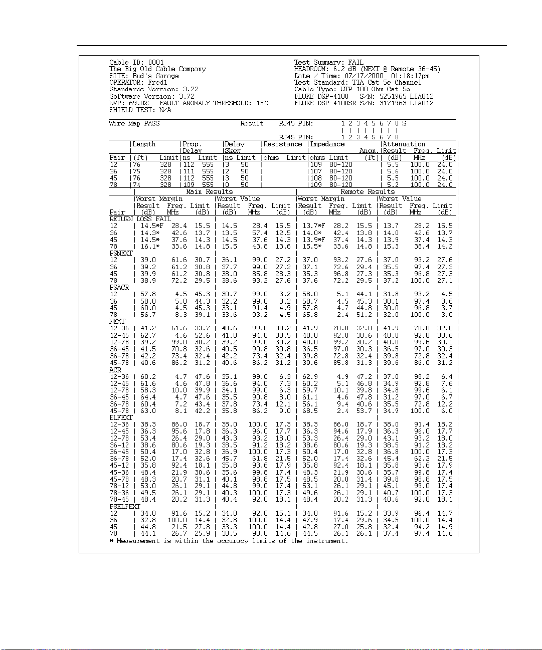
Autotest
The Autotest Report
3
Figure 3-12. Autotest Report in Tabular Format
oy82f.bmp
3-33
Page 98

DSP-4000 Series
Users Manual
Operator: JOHN DOE Test Standard: TIA Cat 6 Basic Link
Standards Version: 4.06 Software Version: 4.06 Cable Type: UTP 100 Ohm Cat 6
NVP: 69.0% Fault Anomaly Threshold: 15% FLUKE DSP-4100 S/N: 1234567 LIA081
Shield Test: N/A FLUKE DSP-4100SR S/N: 0000001 LIA081
Wire Map
PASS
Length (ft), Limit 308 [Pair 12] 111
Prop. Delay (ns), Limit 518 [Pair 12] 163
Delay Skew (ns), Limit 45 [Pair 12] 7
Resistance (ohms)
Impedance (ohms), Limit 80-120 [Pair 12] 114
Anomaly (ft)
Attenuation (dB) [Pair 36] 12.6
Frequency (MHz) 250.0
Limit (dB) 31.8
PASS MAIN MAINSR SR
Worst Pair 12-36 36-45 12-36 36-45
NEXT (dB) 63.4 43.2 43.8 43.2
Freq. (MHz) 13.0 242.0 222.5 242.0
Limit (dB) 56.1 35.5 36.1 35.5
Worst Pair 36 45 36 45
PSNEXT (dB) 40.7 41.7 40.7 41.7
Freq. (MHz) 223.0 242.0 223.0 242.0
Limit (dB) 33.6 33.0 33.6 33.0
PASS MAIN MAINSR SR
Worst Pair 78-36 12-45 36-45 36-45
ELFEXT (dB) 28.0 30.6 27.6 27.2
Freq. (MHz) 184.0 144.5 227.5 227.5
Limit (dB) 19.9 22.0 18.0 18.0
Worst Pair 36 36 36 36
PSELFEXT (dB) 25.8 26.0 25.4 25.4
Freq. (MHz) 184.5 185.5 247.0 232.5
Limit (dB) 16.9 16.8 14.3 14.8
PASS MAIN MAINSR SR
Worst Pair 12-36 12-45 12-36 36-45
ACR (dB) 60.7 67.0 31.5 31.2
Freq. (MHz) 12.9 8.9 240.0 242.0
Limit (dB) 49.5 53.2 4.5 4.3
Worst Pair 12 12 36 36
PSACR (dB) 59.3 61.4 28.8 29.3
Freq. (MHz) 12.9 12.3 223.0 242.0
Limit (dB) 47.2 47.7 3.7 1.7
PASS MAIN MAINSR SR
Worst Pair 12 45 45 78
RL (dB) 21.0 20.8 18.5 17.3
Freq. (MHz) 13.2 16.6 249.0 250.0
Limit (dB) 19.0 19.0 11.3 11.3
Compliant Network Standards:
10BASE-T 100BASE-TX 100BASE-T4
1000BASE-T ATM-25 ATM-51
ATM-155 100VG-AnyLan TR-4
TR-16 Active TR-16 Passive
1
|
2
1
|
|
|
|
|
|
|
8
7
6
5
4
3
8
7
6
5
4
3
2
Worst Margin Worst Value
Test Summary: PASS
Cable ID: ROOM123, PORT B
Headroom: 7.3 dB (NEXT 12-36)
Site: ABC BANK
Date / Time: 08/09/2000 09:06:17am
S
50
25
0
-25
-50
0 407
100
80
60
40
20
0
1 350
100
80
60
40
20
0
1 350
100
80
60
40
20
0
1 350
60
HDTDR%
(ft)
NEXTdB
Frequency (MHz)
ELFEXTdB
Frequency (MHz)
ACRdB
Frequency (MHz)
RLdB
50
40
30
20
10
0
1 350
Frequency (MHz)
60
50
40
30
20
10
100
80
60
40
20
100
80
60
40
20
100
80
60
40
20
60
50
40
30
20
10
AttenuationdB
0
1 350
Frequency (MHz)
NEXT @ RemotedB
0
1 350
Frequency (MHz)
ELFEXT @ RemotedB
0
1 350
Frequency (MHz)
ACR @ RemotedB
0
1 350
Frequency (MHz)
RL @ RemotedB
0
1 350
Frequency (MHz)
3-34
Figure 3-13. Autotest Report in Graphical Format
oy81f.wmf
Page 99

Running Individual Tests
Chapter 4 provides the following information:
• Instructions for running Single Tests on twisted pair cabling.
• Descriptions of the test results produced by the HDTDX analyzer and
HDTDR test.
• Instructions for running Single Tests on coaxial cabling.
• Instructions for using the tests available in the MONITOR mode.
• Instructions for using the tone generator.
Single Tests for Twisted Pair Cabling
The SINGLE TEST mode on the rotary switch allows individual execution of
many of the tests available in the Autotest mode. SINGLE TEST mode features
two additional tests: the HDTDX (High-Definition Time Domain Crosstalk)
analyzer and the HDTDR (High-Definition Time Domain Reflectometry) test.
Chapter 4
Single tests help you isolate cable failures and quickly determine if repairs are
good. To certify a cable installation, you should run an Autotest with the
appropriate test standard.
4-1
Page 100

DSP-4000 Series
Users Manual
Scanning Function
The Single Test versions of the wire map, resistance, HDTDR, and HDTDX
analyzer tests include a scanning function, which you can activate by pressing the
# Scanning ON softkey. The scanning function runs the test repeatedly and
updates the display each time a test is complete. This function is useful for finding
intermittent problems on a cable.
To extend battery life, connect the ac adapter/charger when using
the scanning function for more than 1 minute.
When to Use a Remote Unit
A remote unit is required only when testing twisted pair cabling. Table 4-1 shows
which cable tests require a remote and which remotes support each test.
If a remote unit is detected at the start of a Single Test, the test tool runs a wire
map test before running the selected test. If the wire map test fails, the test tool
stops the test and displays the wire map. Press $ Continue Test to run
the selected test.
Note
Note
The DSP-4100 and DSP-4300 test tools are compatible only with
DSP-4100SR and DSP-4300SR remote units, respectively. The DSP4100 and DSP-4300 remotes are not compatible with DSP-100,
DSP-2000, or DSP-4000 test tools.
4-2
 Loading...