

Page 1

DPCTrack2TM
Calibration Management Software
Users Manual
August 2011
© 2011 Fluke Corporation. All rights reserved. All product names are trademarks of their respective companies.
Shop for Fluke products online at:
www.MyFlukeStore.com
1.877.766.5412
Page 2

License Agreement
This software and accompanying documentation are protected by United States copyright
law and also International Treaty provisions. Any use of this software in violation of
copyright law or the terms of this agreement will be prosecuted fully.
DPCTrack2 is copyright © 2011 by the Fluke Corporation, all rights reserved.
Fluke authorizes you to make archival copies of this software for the sole purpose of
backing up and protecting your investment from loss. Under no circumstances may you
copy this software or documentation for the purposes of distribution to others. Under no
conditions may you remove the copyright notices made part of the software
documentation.
Fluke warrants that the software will function as described in this document or in the
online help for a period of 60 days from receipt. If you encounter a bug or deficiency, we
will require a problem report detailed enough to allow us to find and fix the problem. If
you properly notify us of such a software problem within the warranty period, Fluke will
update the defective software at no cost to you.
Fluke assumes no liability for the use of DPCTrack2 beyond the original purchase
price of the software. In no event will Fluke be liable to you for additional damages,
including any lost profits, lost savings, or other incidental or consequential damages
arising out of the use of or inability to use these programs, even if Fluke has been
advised of the possibility of such damages.
By using this software you agree to the terms of this section. If you do not agree, you
should immediately return the entire DPCTrack2 package.
All Fluke product names are trademarks or registered trademarks of the Fluke
Corporation. Other brand and product names are trademarks or registered trademarks of
their respective holders.
Shop for Fluke products online at:
www.MyFlukeStore.com
1.877.766.5412
Page 3

Table of Contents
Chapter Title Page
1 Introduction ......................................................................................... 1-1
1.1 Introduction..................................................................................................1-3
2 Installing DPCTrack2 .......................................................................... 2-1
2.1 DPCTrack2 Installation ...............................................................................2-3
2.2 System Requirements ..............................................................................2-3
2.3 Procedures ...............................................................................................2-3
2.4 Licensing .................................................................................................2-3
3 Getting Started .................................................................................... 3-1
3.1 Starting the Program ....................................................................................3-3
3.2 Logging onto the System .............................................................................3-3
3.3 Security ........................................................................................................3-3
3.4 Predefined User Groups, User IDs and Passwords ......................................3-4
3.5 About the Sample Records...........................................................................3-4
3.6 Import DPCTrack Data................................................................................3-4
3.7 Common Usage Scenario.............................................................................3-5
3.7.1 Instrument Record Creation / Revision / Retirement ..........................3-5
3.7.2 Test Instrument Record Creation / Revision / Retirement...................3-5
3.7.3 Use of your Company’s Calibration Program .....................................3-5
3.7.4 Upload/Download................................................................................3-5
3.7.5 Reports.................................................................................................3-6
4 Home Screen ....................................................................................... 4-1
4.1 Using the Home Screen ...............................................................................4-3
4.2 Menu Toolbar ..............................................................................................4-3
4.2.1 File Menu..............................................................................................4-3
4.2.2 Tools Menu...........................................................................................4-5
4.2.3 Records Menu.......................................................................................4-8
4.2.4 Reports Menu .......................................................................................4-8
4.2.5 Lists Menu ............................................................................................4-8
4.2.6 Help Menu ............................................................................................4-8
4.3 Main Toolbar ...............................................................................................4-9
i
Shop for Fluke products online at:
www.MyFlukeStore.com
1.877.766.5412
Page 4

DPCTrack2
Users Manual
4.4 Navigation Toolbar ......................................................................................4-9
4.5 Work Area....................................................................................................4-9
5 Overview of Standard Screens........................................................... 5-1
5.1 Standard Screens..........................................................................................5-3
5.2 Overview of Buttons....................................................................................5-4
5.2.1 Add New Record ..................................................................................5-4
5.2.2 Save Record..........................................................................................5-4
5.2.3 Copy Current Record............................................................................5-4
5.2.4 Find Record ..........................................................................................5-4
5.2.5 List Records..........................................................................................5-4
5.2.6 Cancel Changes ....................................................................................5-4
5.2.7 Print Master Report ..............................................................................5-4
5.2.8 Preview Master Report .........................................................................5-4
5.2.9 Show Work History..............................................................................5-4
5.2.10 Close Form .........................................................................................5-4
5.2.11 Help ....................................................................................................5-4
5.3 Data Fields/Lists Menu................................................................................5-4
5.4 File Menu.....................................................................................................5-5
5.5 Edit Menu ....................................................................................................5-5
5.6 Reports Menu...............................................................................................5-5
6 User Administration and Levels of Access....................................... 6-1
6.1 Employee Record Screen.............................................................................6-3
6.1.1 General Info Tab...................................................................................6-3
6.1.3 Force Log Off User ..............................................................................6-5
6.2 User Groups Screen .....................................................................................6-5
6.2.1 Group Type...........................................................................................6-5
6.2.2 Members Tab........................................................................................6-6
6.2.3 Access Levels Tab................................................................................6-6
6.2.4 Reminder Options Tab .........................................................................6-7
6.3 User Administration Screen.........................................................................6-8
7 System Options ................................................................................... 7-1
7.1 System Options............................................................................................7-3
7.1.1 Database Name.....................................................................................7-3
7.2 System Settings Tab.....................................................................................7-4
7.2 System Settings Tab.....................................................................................7-4
7.2.1 Last Date The System Database Was Backed Up ................................7-4
7.2.2 Number Of Days Between Backup Warnings......................................7-4
7.2.3 Number Of Days Before User’s Password Expires..............................7-4
7.2.4 Number of Logons Before Disabling (“0” = Never Disable) ...............7-4
7.2.5 Minimum Password Length..................................................................7-4
7.2.6 Number Of Passwords To Remember ..................................................7-4
7.2.7 Minimum Password Age To Allow Change (Days).............................7-5
7.2.8 Number Of Minutes Before Time-Out .................................................7-5
7.2.9 System Date Format .............................................................................7-5
7.2.10 System Decimal Number Format .......................................................7-5
7.2.11 Default Skin........................................................................................7-5
7.2.12 Allow User Skin Override ..................................................................7-5
7.2.15 Warn On Overdue Test Instruments During Cal Entry ......................7-6
ii
Shop for Fluke products online at:
www.MyFlukeStore.com
1.877.766.5412
Page 5

Contents (continued)
8 User Defined Labels............................................................................ 8-1
8.1 User Defined Labels ....................................................................................8-3
8.2 Column Descriptions ...................................................................................8-3
8.3 Modifying Field Labels ...............................................................................8-4
9 Company Record Screen.................................................................... 9-1
9.1 Company Records........................................................................................9-3
9.2 Tabbed Notebook Section............................................................................9-3
9.2.1 General Info Tab...................................................................................9-3
9.2.1.1 Address Lines 1 & 2, City, State, Zip & Country .........................9-3
9.2.1.2 Contact, Phone & Email................................................................9-3
9.2.2 Other Addresses Tab ............................................................................9-4
9.2.3 Options Tab ..........................................................................................9-4
9.2.4 Default Reports Tab .............................................................................9-7
9.3 Change Company Name ..............................................................................9-7
10 User Defined Variables and User Defined Lists ............................... 10-1
10.1 User Defined Options & Required Fields..................................................10-3
10.2 Adding User Defined Variables.................................................................10-3
10.2.1 Selecting a File Type ..........................................................................10-3
10.2.2 Entering the Variable Name ...............................................................10-4
10.2.3 Selecting the Field Data Type ............................................................10-4
10.2.4 Deleting a User Defined Variable ......................................................10-5
10.2.5 Reordering User Defined Variables ...................................................10-5
10.3 User Defined Lists .....................................................................................10-6
10.3.1 Creating a New List Type...................................................................10-6
10.3.2 Creating List Entries for New List Types...........................................10-6
10.4 Configuring Required Fields......................................................................10-7
11 Reminders ............................................................................................ 11-1
11.1 Reminders ..................................................................................................11-3
11.2 Printing Reminders ....................................................................................11-4
12 Standard Lists ..................................................................................... 12-1
12.1 Standard Lists ............................................................................................12-3
12.2 List Screens................................................................................................12-3
12.2.1 Calibration Frequency ........................................................................12-3
12.2.2 Status ..................................................................................................12-4
12.2.3 Signal Type.........................................................................................12-5
12.2.5 Locations ............................................................................................12-5
12.2.6 Department .........................................................................................12-5
12.2.7 Vendors...............................................................................................12-6
12.2.8 Instrument Type..................................................................................12-6
12.2.9 Responsible Technician......................................................................12-6
12.2.10 Calibration Type...............................................................................12-7
12.2.11 Classification ....................................................................................12-7
12.2.12 Document Type ................................................................................12-7
12.2.13 Equipment Type ...............................................................................12-8
iii
Shop for Fluke products online at:
www.MyFlukeStore.com
1.877.766.5412
Page 6

DPCTrack2
Users Manual
13 Document Records Screen................................................................. 13-1
13.1 Document Records.....................................................................................13-3
13.2 Tabbed Notebook Section..........................................................................13-4
13.2.1 General Info Tab.................................................................................13-4
13.2.2 Signatures Tab ....................................................................................13-5
13.2.3 Procedure Tab.....................................................................................13-5
13.3 File Menu Options .....................................................................................13-5
13.3.1 New Record[Ctrl + N] ........................................................................13-5
13.3.2 Save Record[Ctrl + S] ........................................................................13-5
13.3.3 Find Record[Ctrl + F].........................................................................13-5
13.3.4 Print Record[Ctrl + P] ........................................................................13-5
13.3.5 Print Preview].....................................................................................13-5
13.3.6 List Records........................................................................................13-5
13.3.7 Delete Record .....................................................................................13-6
13.3.8 Close Form .........................................................................................13-6
13.3.9 Exit DPCTrack2 .................................................................................13-6
14 Equipment Record Screen.................................................................. 14-1
14.1 Equipment Records....................................................................................14-3
14.2 Tabbed Notebook Section..........................................................................14-3
14.2.1 General Info Tab.................................................................................14-3
14.2.2 Additional Info Tab ............................................................................14-4
14.2.3 Instruments/Loops Tab.......................................................................14-4
14.2.4 User Defined Tab ...............................................................................14-4
14.2.5 Notes Tab............................................................................................14-5
14.3 File Menu Options .....................................................................................14-5
14.3.1 New Record[Ctrl + N] ........................................................................14-5
14.3.2 Save Record[Ctrl + S] ........................................................................14-5
14.3.3 Find Record[Ctrl + F].........................................................................14-5
14.3.4 List Records........................................................................................14-5
14.3.5 Delete Record .....................................................................................14-5
14.3.6 Close Form .........................................................................................14-6
14.3.7 Exit DPCTrack2 .................................................................................14-6
15 Instrument Record Screen.................................................................. 15-1
15.1 Instrument Records ....................................................................................15-3
15.2 Tabbed Notebook Section..........................................................................15-3
15.2.1 General Info Tab.................................................................................15-3
15.2.2 Calibration Points Tab........................................................................15-5
15.2.3 Additional Info Tab ............................................................................15-16
15.2.4 User Defined Tab ...............................................................................15-17
15.2.5 Notes Tab............................................................................................15-17
15.3 File Menu Options .....................................................................................15-17
15.3.1 New Record [Ctrl + N] .......................................................................15-17
15.3.2 Copy Record [Ctrl + Y]......................................................................15-17
15.3.3 Save Record [Ctrl + S] .......................................................................15-17
15.3.4 Find Record [Ctrl + F]........................................................................15-17
15.3.5 List Records [Ctrl + L] .......................................................................15-17
15.3.6 Show Work History [Ctrl + K]...........................................................15-17
15.3.7 Delete Record .....................................................................................15-17
15.3.8 Close Form .........................................................................................15-18
15.3.9 Exit DPCTrack2 .................................................................................15-18
iv
Shop for Fluke products online at:
www.MyFlukeStore.com
1.877.766.5412
Page 7

Contents (continued)
16 Loop Record Screen ........................................................................... 16-1
16.1 Loop Records.............................................................................................16-3
16.2 Tabbed Notebook Section..........................................................................16-3
16.2.1 General Info Tab.................................................................................16-4
16.2.2 Calibration Points Tab........................................................................16-5
16.2.3 Additional Info Tab ............................................................................16-5
16.2.4 User Defined Tab ...............................................................................16-6
16.2.5 Notes Tab............................................................................................16-6
16.3 File Menu Options .....................................................................................16-6
16.3.1 New Record[Ctrl + N] ........................................................................16-6
16.3.2 Copy Record[Ctrl + Y].......................................................................16-6
16.3.3 Save Record[Ctrl + S] ........................................................................16-7
16.3.4 Find Record[Ctrl + F].........................................................................16-7
16.3.5 List Records[Ctrl + L] ........................................................................16-7
16.3.6 Show Work History[Ctrl + K]............................................................16-7
16.3.7 Delete Record .....................................................................................16-7
16.3.8 Close Form .........................................................................................16-7
16.3.9 Exit DPCTrack2 .................................................................................16-7
17 Test Instrument Record Screen ......................................................... 17-1
17.1 Test Instrument Records ............................................................................17-3
17.2 Tabbed Notebook Section..........................................................................17-3
17.2.1 General Info Tab.................................................................................17-3
17.2.2 Calibration Points Tab........................................................................17-5
17.2.3 Additional Info Tab ............................................................................17-5
17.2.4 User Defined Tab ...............................................................................17-5
17.2.5 Notes Tab............................................................................................17-5
17.3 File Menu Options .....................................................................................17-5
17.3.1 New Record[Ctrl + N] ........................................................................17-5
17.3.2 Copy Record[Ctrl + Y].......................................................................17-5
17.3.3 Save Record[Ctrl + S] ........................................................................17-5
17.3.4 Find Record[Ctrl + F].........................................................................17-5
17.3.5 List Records[Ctrl + L] ........................................................................17-6
17.3.6 Show Work History[Ctrl + K]............................................................17-6
17.3.7 Delete Record .....................................................................................17-6
17.3.8 Close Form .........................................................................................17-6
17.3.9 Exit DPCTrack2 .................................................................................17-6
18 Upload/Do wnload Screen ................................................................... 18-1
18.1 Getting Started ...........................................................................................18-3
18.2 File Menu Options .....................................................................................18-4
18.2.1 Initiate Download/Upload ..................................................................18-4
18.2.2 Close Form .........................................................................................18-4
18.2.3 Exit DPCTrack2 .................................................................................18-4
18.3 Features......................................................................................................18-4
18.3.1 Clear Calibrator Memory....................................................................18-4
18.3.2 Set Calibrator Date/Time to Current Date/Time ................................18-5
18.3.3 View Number of Test Results ............................................................18-5
18.3.4 View/Edit Session Log .......................................................................18-5
18.4 Lists............................................................................................................18-5
18.5 Help............................................................................................................18-5
18.6 Options.......................................................................................................18-5
18.6.1 Download Options..............................................................................18-5
18.6.2 Upload Options...................................................................................18-7
v
Shop for Fluke products online at:
www.MyFlukeStore.com
1.877.766.5412
Page 8

DPCTrack2
Users Manual
18.7 Downloading Calibration Items as Tasks ..................................................18-7
18.7.1 Download By......................................................................................18-7
18.7.2 Tag List Operations ............................................................................18-9
18.7.3 Tag List Edit Functions ......................................................................18-10
18.7.4 Tag List Information Functions..........................................................18-10
18.7.5 Adding to the Tag List........................................................................18-11
18.7.6 Removing Items from the Tag List.....................................................18-11
18.7.7 Tag Construction ................................................................................18-11
18.8 Uploading Results as Calibrations .............................................................18-12
18.8.1 Assign Technician to Calibrations......................................................18-12
18.8.2 Default Calibration Type for Uploaded Calibrations .........................18-13
18.8.3 Default Test Instrument Warning Options .........................................18-13
18.8.4 Initiate Upload....................................................................................18-13
18.9 Test Instrument Recognition......................................................................18-16
19 Calibration Screen............................................................................... 19-1
19.1 Calibration Records ...................................................................................19-3
19.2 Tabbed Notebook Section..........................................................................19-3
19.2.1 Header Fields......................................................................................19-3
19.2.2 Item Info (As of Calibration Record Entry Date)...............................19-4
19.2.3 General Calibration Info.....................................................................19-4
19.3 Test Results Tab.........................................................................................19-5
19.3.1 Test Point Groups ...............................................................................19-5
19.3.2 Separate As Found/As Left Inputs......................................................19-6
19.3.3 Modifying Calibration Specifications ................................................19-6
19.3.4 Classifying the Result of a Calibration...............................................19-7
19.3.5 Automatic Warnings and Messages ...................................................19-8
19.3.6 Warnings and Messages That May Appear as a Result of
Options and Default Settings.............................................................19-9
19.3.7 Entering Calibrations in Multi-Mode .................................................19-10
19.4 Test Instruments Tab..................................................................................19-11
19.4.1 How Instrument Types Affect the Available Test Instrument List ....19-12
19.4.2 Show All.............................................................................................19-12
19.5 SOP Tab.....................................................................................................19-12
19.6 User Defined Tab.......................................................................................19-12
19.7 Notes Tab...................................................................................................19-13
20 Import DPCTrack Data ........................................................................ 20-1
20.1 Import DPCTrack Data..............................................................................20-3
20.1.1 Field Mapping ....................................................................................20-4
20.1.2 Frequency Mapping............................................................................20-4
20.2 Possible Errors/Warnings...........................................................................20-5
20.3 Compatibility Limitations..........................................................................20-5
20.3.1 Limitations For Instrument Imports ...................................................20-5
20.3.2 Limitations For History Imports.........................................................20-5
21 Advanced Queries............................................................................... 21-1
21.1 Advanced Queries......................................................................................21-3
21.1.1 Running Previously Saved Advanced Queries...................................21-3
21.1.2 Creating New Advanced Queries and Modifying Existing Queries...21-3
21.1.3 Action Button Sets..............................................................................21-9
21.1.4 Navigating Between Records Included in an Advanced Query List ..21-10
21.1.5 Printing Lists and Saving Them to External Files..............................21-11
21.1.6 Using Advanced Queries in Other Parts of the Program....................21-11
vi
Shop for Fluke products online at:
www.MyFlukeStore.com
1.877.766.5412
Page 9

Contents (continued)
22 DPCTrack Explorer.............................................................................. 22-1
22.1 DPCTrack Explorer ...................................................................................22-3
22.1.1 Grouping.............................................................................................22-4
22.1.2 Pop-up Menu Options ....................................................................22-4
22.1.3 Status Indicator Icons .........................................................................22-5
22.1.4 Resetting the Tree...............................................................................22-5
22.1.5 Displaying Additional Information ....................................................22-5
23 Reporting System................................................................................ 23-1
23.1 Reports.......................................................................................................23-3
23.1.1 Report Parameters Tab .......................................................................23-3
23.1.2 Advanced Selection Tab.....................................................................23-4
23.2 Other Options Available on the Reports Menu..........................................23-5
23.2.1 Set Report Directory...........................................................................23-5
23.2.2 Report Maintenance............................................................................23-6
23.3 Printing ..................................................................................................23-6
23.4 Setting Up New Reports ............................................................................23-6
23.4.1 Custom Reports ..................................................................................23-6
23.4.2 Report Maintenance............................................................................23-7
23.5 Adding New Reports from Scripts.............................................................23-9
23.6 Deleting Reports ........................................................................................23-10
24 The Logged Data Screen .................................................................... 24-1
24.1 What is Logged Data?................................................................................24-3
24.2 Uploading Logged Data.............................................................................24-4
24.2.1 Selecting Port......................................................................................24-4
24.2.2 Upload Logs Button ...........................................................................24-5
24.2.3 Show Logged Data Button .................................................................24-6
24.2.4 Log Record .........................................................................................24-6
24.3 Viewing Log Records ................................................................................24-8
24.3.1 Listing Log Records ...........................................................................24-9
24.3.2 Navigating Log Records.....................................................................24-9
24.4 Viewing Logged Data Report ....................................................................24-10
25 Backing Up and Restoring Data......................................................... 25-1
25.1 Backing Up ................................................................................................25-3
25.2 Restore From Backup ................................................................................25-4
26 Troubleshooting .................................................................................. 26-1
26.1 Troubleshooting - Downloading Instruments as Tasks..............................26-3
26.2 Troubleshooting - Device Communication................................................26-3
26.3 Troubleshooting - Uploading Results ........................................................26-4
Appendix A Report Descriptions Listed by Groups ..................................... A-1
Alert Group ........................................................................................................A-1
Calibration Alert Report ................................................................................A-1
Failed Calibrations Report.............................................................................A-1
Calibration Group ..............................................................................................A-1
Calibration Bar Code Label...........................................................................A-1
Calibration Label ...........................................................................................A-1
Instrument Calibration Report (Spec Summary) ...........................................A-1
Instrument Calibration Report (Specs/Test Point).........................................A-1
vii
Shop for Fluke products online at:
www.MyFlukeStore.com
1.877.766.5412
Page 10

DPCTrack2
Users Manual
Instrument Test Point Analysis......................................................................A-2
Instrument Test Point Trend..........................................................................A-2
Loop Calibration Report (Spec Summary)....................................................A-2
Loop Calibration Report (Specs/Test Point) .................................................A-2
Loop Test Point Analysis ..............................................................................A-2
Loop Test Point Trend...................................................................................A-2
Test Instrument Calibration (Spec Summary) ...............................................A-2
Test Instrument Calibration (Specs/Test Point).............................................A-2
Test Instrument Test Point Analysis..............................................................A-3
Test Instrument Test Point Trend ..................................................................A-3
Company Group.................................................................................................A-3
Events Due (This Company) .........................................................................A-3
Document Group................................................................................................A-3
Document Report...........................................................................................A-3
Documents Due Report .................................................................................A-3
Equipment Group...............................................................................................A-3
Equipment Bar Code Label ...........................................................................A-3
Instrument Group...............................................................................................A-3
Instrument Bar Code Label............................................................................A-3
Instrument Master (Spec Summary)..............................................................A-3
Instrument Master (Specs/Test Point) ...........................................................A-3
Instrument Worksheet (Spec Summary)........................................................A-4
Instrument Worksheet (Spec/Test Point).......................................................A-4
Instrument Due Report ..................................................................................A-4
Inventory Group.................................................................................................A-4
Instrument Inventory .....................................................................................A-4
Loop Inventory ..............................................................................................A-4
Test Instrument Inventory .............................................................................A-4
Logged Data Group ...........................................................................................A-4
Data Log Report ............................................................................................A-4
Loop Group........................................................................................................A-4
Loop Bar Code Label ....................................................................................A-4
Loop Master (Spec Summary).......................................................................A-4
Loop Master (Spec/Test Point)......................................................................A-5
Loop Worksheet (Spec Summary) ................................................................A-5
Loop Worksheet (Specs/Test Point) ..............................................................A-5
Loops Due Report..........................................................................................A-5
Test Instrument Group .......................................................................................A-5
Test Instrument Bar Code Label....................................................................A-5
Test Instrument Master (Spec Summary)......................................................A-5
Test Instrument Master (Specs/Test Point) ...................................................A-5
Test Instrument Reverse Traceability............................................................A-5
Test Instrument Worksheet (Spec Summary)................................................A-5
Test Instrument Worksheet (Specs/Test Point) .............................................A-5
Test Instrument Due Report ..........................................................................A-6
User Group.........................................................................................................A-6
Active Users Report ......................................................................................A-6
Security Log Report ......................................................................................A-6
Appendix B Frequently Asked Questions ..................................................... B-1
Frequently Asked Questions List.......................................................................B-1
viii
Shop for Fluke products online at:
www.MyFlukeStore.com
1.877.766.5412
Page 11

Chapter 1
Introduction
Title Page
1.1 Introduction............................................................................................. 1-3
Shop for Fluke products online at:
www.MyFlukeStore.com
1-1
1.877.766.5412
Page 12

DPCTrack2
Users Manual
1-2
Shop for Fluke products online at:
www.MyFlukeStore.com
1.877.766.5412
Page 13

Introduction
1.1 Introduction 1
1.1 Introduction
This manual has been designed to fit the way users say they work. It is set up logically,
focusing on different areas of the program in the order that they will most likely be used.
The emphasis is on getting the job done in the easiest and most efficient way possible.
This manual was also written under the assumption that the DPCTrack2 program being
used is a full program, including all calibration and system security features. In addition,
it is assumed that the reader has been given access to all areas of the program, however,
this may not be the case. If you notice that the company name, menu items, speed
buttons, screen options, etc. are grayed out, either the program you purchased did not
include those features or your User ID has not been granted access to those areas of the
program.
The initial content of this manual will provide you with an overview of how to get started
with the software installation instructions, logon procedures and standard screen features.
All screens have a uniform look with similar speed buttons and menus, making it easy for
you to adapt to the system quickly.
Each subsequent chapter individually addresses one of the program’s screens or major
functions. In each of these chapters you will find a full description and explanation of the
screens features, as well as detailed, hands-on operating instructions.
The online help system included with DPCTrack2 is full of useful information, similar to
that provided in this manual. It is available at all times when using the program, either by
accessing the Help menu, left-clicking the speed buttons labeled as such, or by pressing
the “F1” key.
Shop for Fluke products online at:
www.MyFlukeStore.com
1-3
1.877.766.5412
Page 14

DPCTrack2
Users Manual
1-4
Shop for Fluke products online at:
www.MyFlukeStore.com
1.877.766.5412
Page 15

Chapter 2
Installing DPCTrack2
Title Page
2.1 DPCTrack2 Installation .......................................................................... 2-3
2.2 System Requirements ......................................................................... 2-3
2.3 Procedures .......................................................................................... 2-3
2.4 Licensing ............................................................................................ 2-3
Shop for Fluke products online at:
www.MyFlukeStore.com
2-1
1.877.766.5412
Page 16

DPCTrack2
Users Manual
2-2
Shop for Fluke products online at:
www.MyFlukeStore.com
1.877.766.5412
Page 17

Installing DPCTrack2
2.1 DPCTrack2 Installation 2
2.1 DPCTrack2 Installation
2.2 System Requirements
To use the DPCTrack2, it is recommended that you have the following hardware and
software:
• A Pentium class 667 MHz or higher computer with a minimum of 256 MB of RAM
(512 MB or more recommended)
• Windows XP or later operating system versions
• A hard disk with at least 500 MB of free space
2.3 Procedures
Single-User License:
• Insert the DPCTrack2 CD into your computer’s CD-ROM drive. If the program does
not autostart, Run “setup.exe”. Follow the prompts on your screen to complete
installation.
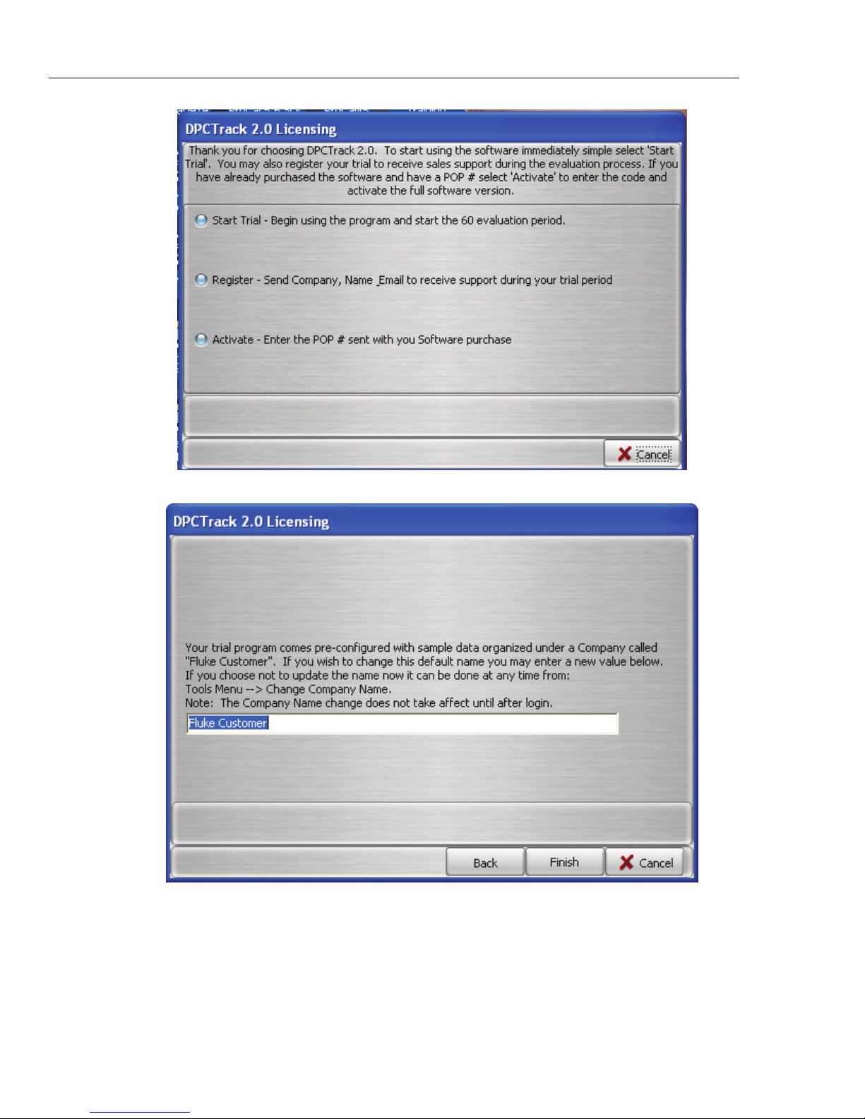
2.4 Licensing
The first time you run DPCTrack2 you will see the “DPCTrack2 Licensing” screen with
three options. See Figure 2.1 below.
Start Trial: This will allow you to enter DPCTrack2 for the first 60 days of use without
further action. After 60 days, all features of the DPCtrack2 System except those to
Upload, Download & View the Logs will be restricted. Your trial program comes preconfigured with sample data organized under a company called “Fluke Customer”. If you
wish to change this default name you may do so when you start your trial. See Figure 2.2
Register: Registering the trial will enable you to receive sales support during the
evaluation process. Customers are given the option to register at the following times:
• During the 1
• Every time a Trial expiration warning is shown (if they have not already registered)
• Through a menu option Help Register Now (if they have not already registered)
The registration process is identical, regardless of when the option is selected. The
customer is prompted to enter their basic information – Company, First Name, Last
Name, email & Phone
Activate: Upon selecting Activate you will be prompted for a POP # and other
information for verification. This data is sent for confirmation and used to generate an
Activation Code which will be sent to you for entry it into the DPCTrack2 System.
st
run when they select to run a Trial (instead of Activate)
Shop for Fluke products online at:
www.MyFlukeStore.com
2-3
1.877.766.5412
Page 18
DPCTrack2
Users Manual
Figure 2.1
2-4
Shop for Fluke products online at:
Figure 2.2
www.MyFlukeStore.com
1.877.766.5412
Page 19

Installing DPCTrack2
2.1 DPCTrack2 Installation 2
Notes
• The installation directory [INSTALLDIR] defaults to:
“C:\DPCTrack2”. This can be overridden during the installation
process.
• The data directory [DATADIR] defaults to:
“C:\ DPCTrack2\Data”. This can also be overridden during the
installation process. The data directory can be on a shared network
storage device but only this version of DPCTrack2 that is currently
being installed will be able to access it.
Shop for Fluke products online at:
www.MyFlukeStore.com
2-5
1.877.766.5412
Page 20

DPCTrack2
Users Manual
2-6
Shop for Fluke products online at:
www.MyFlukeStore.com
1.877.766.5412
Page 21

Chapter 3
Getting Started
Title Page
3.1 Starting the Program................................................................................ 3-3
3.2 Logging Onto the System........................................................................ 3-3
3.3 Security.................................................................................................... 3-3
3.4 Predefined User Groups, User IDs and Passwords.................................. 3-4
3.5 About the Sample Records ...................................................................... 3-4
3.6 Import DPC/Track Data........................................................................... 3-4
3.7 Common Usage Scenario ........................................................................ 3-5
3.7.1 Instrument Record Creation / Revision / Retirement ............................ 3-5
3.7.1.1 Creating Instrument Records in DPCTrack2 ......................................... 3-5
3.7.1.2 Revising a Master Record...................................................................... 3-5
3.7.1.3 Retiring an Instrument........................................................................... 3-5
3.7.2 Test Instrument Record Creation / Revision / Retirement..................... 3-5
3.7.3. Use of your Company’s Calibration Program ......................................... 3-5
3.7.4 Upload/Download.................................................................................. 3-5
3.7.4.1 Downloading Tasks ............................................................................... 3-6
3.7.4.2 Uploading Results ................................................................................. 3-6
3.7.5 Reports................................................................................................... 3-6
Shop for Fluke products online at:
www.MyFlukeStore.com
3-1
1.877.766.5412
Page 22

DPCTrack2
Users Manual
3-2
Shop for Fluke products online at:
www.MyFlukeStore.com
1.877.766.5412
Page 23
Getting Started
3.1 Starting the Program 3
3.1 Starting the Program
To start DPCTRACK2, double-click on the DPCTrack2 icon located in the DPCTrack2
Group. (Multiple instances of DPCTrack2 may not be run concurrently on the same
machine.)
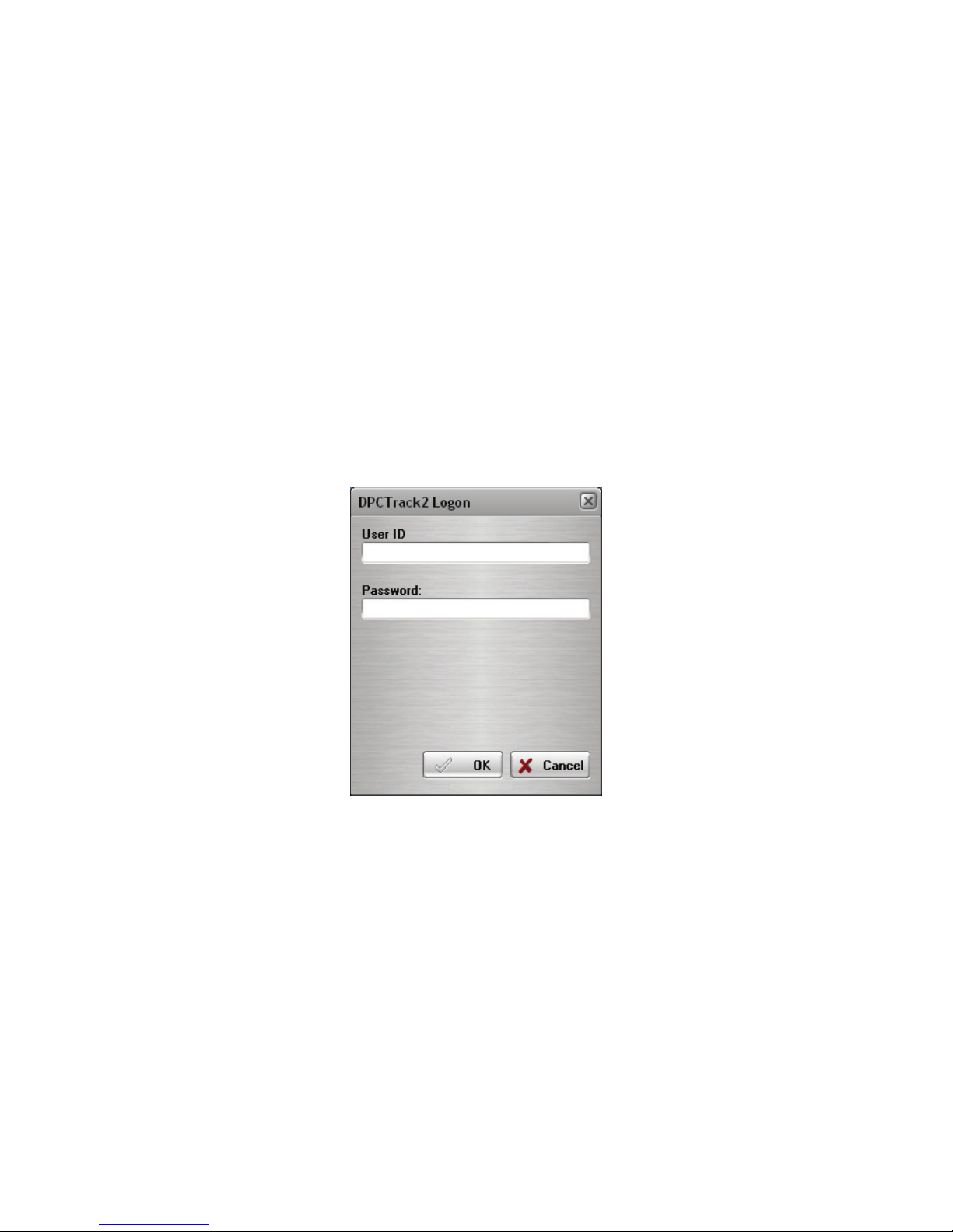
3.2 Logging onto the System
Upon starting DPCTrack2, you will receive a login screen. Login the first time using the
default Admin credentials given below in the Admin user group description section. The
first time you log on, you will be prompted to change the default password to one of your
own choosing.
DPCTrack2 is password protected, so every time you want to use the system, you will
have to enter your "User ID" and "Password". Both the User ID and Password may be
any combination of letters or numbers, although there may be a minimum password
length required, depending on your System settings. (See Chapter 7 SYSTEM OPTIONS,
for details regarding minimum password length.) Also both the User ID and Passwords
are not Case Sensitive. Figure 3.1 shown below, is the screen you will see every time you
log onto DPCTrack2.
3.3 Security
As a measure to prevent unauthorized individuals from gaining access to your records,
DPCTrack2 offers a security feature whereby the administrator may set the number of
times an unsuccessful logon can occur before disabling a User ID. This value is set in the
SYSTEM OPTIONS screen which is available from the File menu at the top left of your
HOME screen (see Chapter 7 for details). An unsuccessful logon occurs when a user
enters an incorrect password for their User ID. When the maximum number of
unsuccessful logons is reached, DPCTrack2 will automatically disable the user, thus
denying them access to the system. When this occurs, only a User that is a member of the
“ADMIN” group can re-enable the User ID. See Chapter 6 for more information on how
to re-enable a user.
Shop for Fluke products online at:
Figure 3.1
www.MyFlukeStore.com
3-3
1.877.766.5412
Page 24

DPCTrack2
Users Manual
3.4 Predefined User Groups, User IDs and Passwords
DPCTRACK2 includes three (3) predefined User Access Groups with Users assigned to
them and one (1) Technician Group with one Technician assigned. The predefined User
Groups are: ADMIN, USER, and READONLY. The Technician Group is TECH. All
DPC/Track users must be assigned to one of the predefined User Access Groups.
The following is a list of the pre-defined User Groups and their descriptions:
Admin
The Admin (Administrator) has full access to all areas of DPCTrack2. Most
notably, the Admin has the ability to perform administrative responsibilities, such
as modifying system options, backing up data, adding technicians and other
users, adding user defined variables, deleting data, among other tasks. Typically,
only one person should serve as the Admin of the DPCTrack2 program. The User
ID and default password for the Admin User group is Admin/Admin.
User
The access rights of the User differ from those of the Admin in that a User cannot
perform administrative tasks. The User has the ability to approve changes, add or
modify records, download and upload tasks to the calibrator and view logged
data. The User ID and default password for the User User Group is User/User.
Read Only
The access rights of the READONLY user are further restricted than those of the
User in that existing data may only be read. However, READONLY user may
download and upload tasks to the calibrator for the purpose of generating Test
Results records. The User ID and default password for READONLY User Group
is READONLY/READONLY.
Technician
There are no access rights for the Technician. The Technician is there for display
purposes only e.g. for Who Calibrated or Responsible Technician. There is no
User ID or password for the Technician.
3.5 About the Sample Records
DPCTrack2 includes a number of sample records intended to help you learn the
operations and features of the program. After becoming familiar with DPCTrack2, you
may want to delete the sample records so as not to interfere with your “real” data. (The
sample records could potentially be included within your reports and data analysis.)
3.6 Import DPC/Track Data
This will allow users to Import DPC/Track data (Instruments, History and Procedures)
into the database. See Chapter 04 Home screen, subsection 4.2.2 Tools Menu.
3-4
Shop for Fluke products online at:
www.MyFlukeStore.com
1.877.766.5412
Page 25

Getting Started
3.7 Common Usage Scenario 3
3.7 Common Usage Scenario
This scenario applies to the activities performed by personnel supporting the DPCTrack2
database such as for instrument calibrations maintained in the DPCTrack2 database
and/or instrument creation/revision/retirement.
3.7.1 Instrument Record Creation / Revision / Retirement
Instrument Records may be created or revised in DPCTrack2 for an instrument when it is
determined that its calibration information will be maintained in the DPCTrack2
database. For existing DPC/Track clients you may move your DPC/Track data to the new
DPCTrack2 database. See Chapter 20 of the User Manuals for information about
importing your data.
3.7.1.1 Creating Instrument Records in DPCTrack2
The Administrator or User will select the “Instruments” button and open the “Instrument
Record” screen, and select “Add New Record” icon to create a new Instrument Record in
DPCTrack2 and “Approve” the record. When setting up the calibration points for an
instrument, select the “Show DPC Settings” to allow you to configure your Source Mode
and Measure Mode. This provides the compatibility between the signal type and the
Source Mode and Measure Mode
3.7.1.2 Revising a Master Record
To revise a Master record, , the Administrator or User will access the Master Record Data
Instrument Record, Loop Record, and/or Test Instrument Record), edit and save the
master record data.
3.7.1.3 Retiring an Instrument
To retire an instrument, the Administrator or User or will access the Instrument Record;
change the status to your Company’s retired status and save the master instrument record
data.
3.7.2 Test Instrument Record Creation / Revision / Retirement
DPCTrack2 stores data for Test Instruments separately. The Administrator or User will
select the “Test Instruments” button and open the “Test Instrument Record” screen, and
select “Add New Record” icon to create a new Test Instrument Record in DPCTrack2
and “Approve” the record. Test Instrument records may be associated with a calibration
record for certification and verification purposes. Calibration records will always retain
the Test Instrument assigned regardless of the Test Instrument’s status, therefore it is
recommended that you do not delete Test Instrument records.
3.7.3. Use of your Company’s Calibration Program
The Administrator or User will select “Reports” “Company” “Events Due (This
Company)” from the Home screen to generate an Events Due Report from DPCTrack2 to
determine the monthly list of instruments due for calibration for the upcoming month.
3.7.4 Upload/Download
The Upload/Download screen is used for calibrator communication. The Administrator or
User will select the “Upload/Download” button to open the “Upload/Download” screen.
Tasks can be downloaded to the calibrator and Test Results can be uploaded from the
calibrator to the DPCTrack2 database. During any Download or Upload operation, the
Options screen allows default values to be set for tasks or results created.
Additionally, calibration records are created when results are uploaded and authorized.
DPCTrack2 also associates the calibration record with the appropriate instrument record.
See Chapter 18 for more Upload/Download details.
Shop for Fluke products online at:
www.MyFlukeStore.com
3-5
1.877.766.5412
Page 26
DPCTrack2
Users Manual
3.7.4.1 Downloading Tasks
There are several methods to choose from to generate a list of Tags to download. Before
initiating the download, connect the calibrator to the serial port and turn the calibrator on.
Your calibrator information should display in the “Calibrator Info” section of the
Upload/Download screen. If the information is not displayed, click the Refresh button.
See Figure 3.2. Select the tags you wish to download and then select the “Initiate
Download” button. After the download process is complete, perform the test with the
calibrator.
3.7.4.2 Uploading Results
To Upload results to DPCTrack2, make sure the calibrator is connected and powered on,
then select the “Initiate Upload” button. You will be required to authorize the results
before they will be added to DPCTrack2.
3.7.5 Reports
After uploading the test results, you can then view your results within DPCTrack2. To
review your results, select the Reports menu in the Home Screen or view the Calibration
record for the instrument by selecting the Calibration button and selecting the instrument
you wish to preview.
Figure 3.2
3-6
Shop for Fluke products online at:
www.MyFlukeStore.com
1.877.766.5412
Page 27

Chapter 4
Home Screen
Title Page
4.1 Using the Home Screen ..........................................................................4-3
4.2 Menu Toolbar ......................................................................................... 4-3
4.2.1 File Menu ........................................................................................... 4-3
4.2.1.1 User Logon..................................................................................... 4-4
4.2.1.1 User Logoff .................................................................................... 4-4
4.2.1.2 Change Password ........................................................................... 4-4
4.2.1.3 Change User................................................................................... 4-4
4.2.1.4 User Administration ....................................................................... 4-4
4.2.1.5 Employee Records ......................................................................... 4-4
4.2.1.6 Group Records ............................................................................... 4-4
4.2.1.7 System Options ..............................................................................4-4
4.2.1.8 Exit DPCTrack2............................................................................. 4-4
4.2.2 Tools Menu......................................................................................... 4-5
4.2.2.1 Backup Database............................................................................ 4-5
4.2.2.2 User Defined Variables.................................................................. 4-5
4.2.2.3 User Defined Labels....................................................................... 4-5
4.2.2.4 User Defined Lists.......................................................................... 4-5
4.2.2.5 Required Fields ..............................................................................4-5
4.2.2.6 Change Company Name ................................................................ 4-5
4.2.2.7 Import DPCTrack Data .................................................................. 4-5
4.2.3 Records Menu..................................................................................... 4-8
4.2.4 Reports Menu ..................................................................................... 4-8
4.2.5 Lists Menu.......................................................................................... 4-8
4.2.6 Help Menu.......................................................................................... 4-8
4.3 Main Toolbar ..........................................................................................4-9
4.4 Navigation Toolbar ................................................................................. 4-9
4.5 Work Area .............................................................................................. 4-9
Shop for Fluke products online at:
www.MyFlukeStore.com
4-1
1.877.766.5412
Page 28

DPCTrack2
Users Manual
4-2
Shop for Fluke products online at:
www.MyFlukeStore.com
1.877.766.5412
Page 29
Home Screen
4.1 Using the Home Screen 4
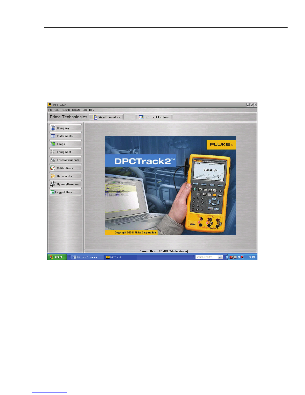
4.1 Using the Home Screen
Figure 4.1 below, is the system’s HOME SCREEN. This is the main screen you work
from when you are using DPCTrack2. It has the buttons and menu items used to activate
every other branch and/or function of the system. Keep in mind that the buttons and menu
items that are available to a user at any given time are strictly dependent upon the level of
system access that they have been granted. An overview of this screen’s sections is
provided below. However, for more detailed information on any of the items mentioned,
please refer to the pages dedicated to those topics in the other sections of this manual.
4.2 Menu Toolbar
The menu toolbar contains six (6) menus, File, Tools, Records, Reports, Lists, and Help,
each of which enables you to perform a number of different actions or functions related
to the system.
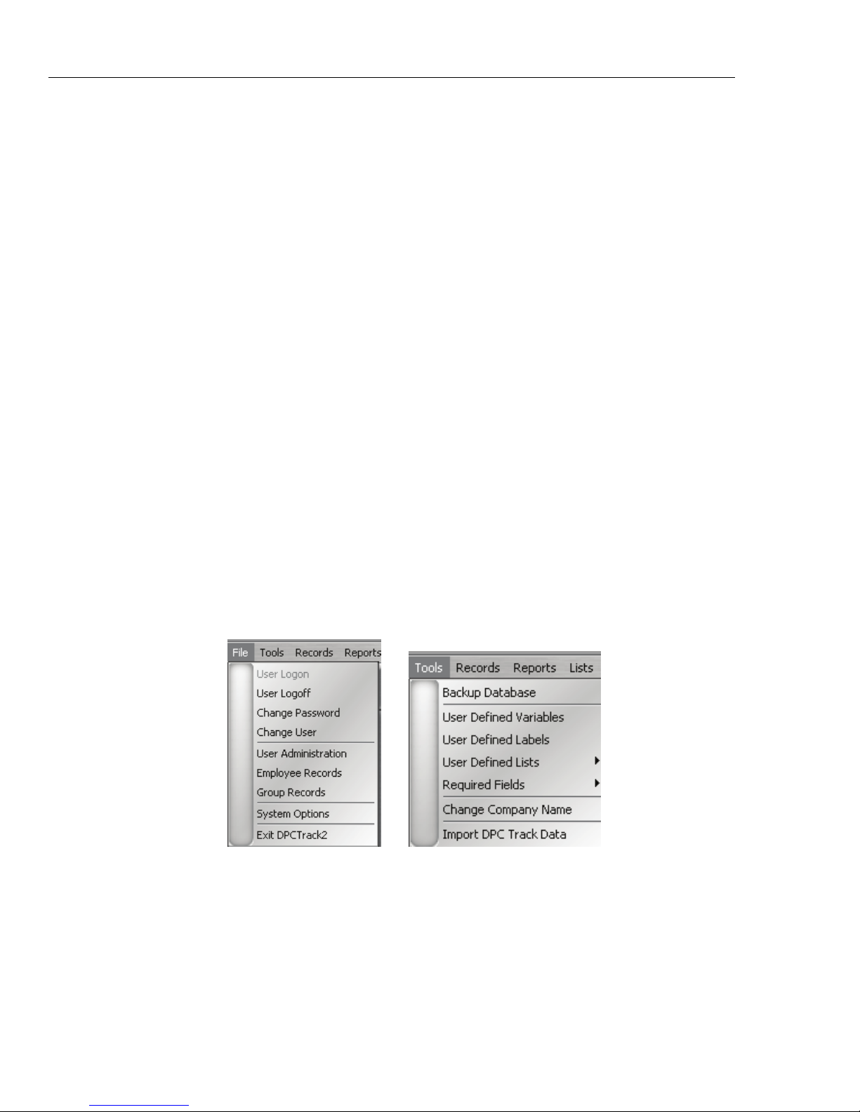
4.2.1 File Menu
Opening the File menu when the HOME SCREEN is displayed provides you with the
following options: (See Figure 4.2 below)
Shop for Fluke products online at:
Figure 4.1
www.MyFlukeStore.com
4-3
1.877.766.5412
Page 30
DPCTrack2
Users Manual
4.2.1.1 User Logon
This option will be grayed out unless there is not a User logged on. If there is no User
logged on this option and Exit DPCTrack2 will be the only accessible choices. Selecting
this option with no User logged on, will bring up the DPCTrack2 logon screen.
4.2.1.1 User Logoff
This will logoff the current user but will not close DPCTrack2
4.2.1.2 Change Password
This will open a new screen requiring the current user to change their password
4.2.1.3 Change User
This will logoff the current user but will not close DPCTrack2
4.2.1.4 User Administration
This screen allows the user to add Employees, Copy an employee record, View a selected
Group or Employee record, (This is covered in depth in Chapter 6)
4.2.1.5 Employee Records
This screen allows the user to view, add or change employee records. (This is covered in
depth in Chapter 6)
4.2.1.6 Group Records
This screen allows the user to add/delete members for groups, the levels of access for
each group and reminder options. (This is covered in depth in Chapter 6)
4.2.1.7 System Options
This screen allows the user to change or modify options that are system wide. (This is
covered in depth in Chapter 7)
4.2.1.8 Exit DPCTrack2
This will logoff the current user and close DPCTrack2
Figure 4.2
Figure 4.3
4-4
Shop for Fluke products online at:
www.MyFlukeStore.com
1.877.766.5412
Page 31

Home Screen
4.2 Menu Toolbar 4
4.2.2 Tools Menu
The Tools menu (See Figure 4.3 above) provides a drop down with the following:
4.2.2.1 Backup Database
This is a shortcut to the Backup utility (See Chapter 25)
4.2.2.2 User Defined Variables
This screen allows users to create, modify and delete fields that will be displayed in the
appropriate User Defined tabs on the Item screens (See Chapter 10)
4.2.2.3 User Defined Labels
This is a shortcut to the User Labels Definition screen where users can view and edit
Labels (See Chapter 8)
4.2.2.4 User Defined Lists
This screen allows the user to add, modify and delete User Defined Lists (See Chapter
10)
4.2.2.5 Required Fields
This screen allows you to set Fields that must be filled in before a Record can be
Approved or a Calibration can be Finalized.
4.2.2.6 Change Company Name
This screen allows users that are in the “ADMIN” Group to change the Company name.
4.2.2.7 Import DPCTrack Data
This will allow users to Import DPC/Track data (Instruments, History and Procedures)
into the database.
Shop for Fluke products online at:
www.MyFlukeStore.com
4-5
1.877.766.5412
Page 32

DPCTrack2
Users Manual
4.2.2.7.1 File Location
Before you start the Import process, it is recommended that you perform a Backup of
your DPCTrack2 database, (refer to Section 4.2.2.1 above) and an Export of your
Instruments, History & Procedures in DPC/Track to make sure that you have the most up
to date records. Refer to the DPC/Track User Manual for more information. If you know
the location for the files you can type the path or select the “Find” button. Select the
following files:
History – hist_out.asc Instrument – inst_out.asc Procedure – proc_out.asc
You may also change the location of the Log file, (it will default to the same location that
the executable resides.)
4-6
Shop for Fluke products online at:
Figure 4.4
www.MyFlukeStore.com
1.877.766.5412
Page 33

Home Screen
4.2 Menu Toolbar 4
4.2.2.7.2 Field Mapping
The “Field Mapping” section allows you to set the “Status”. The dropdown will contain a
list of existing Statuses in the system.
The screen allows you to map the Location, Responsible & Area fields of DPC/Track to
new or different fields in DPCTrack2. The “Frequency Mapping” section allows you to
attempt to map your frequencies from DPC/Track format to DPCTrack2 format.
4.2.2.7.3 Validate Files
The “Validate Files” button will check that the files have the right extension.
4.2.2.7.4 Initiate Import
After you have mapped all areas and validated the file extensions, you can then select the
“Initiate Import” button. You will receive a confirm message first. The “Field Mapping”
section will be replaced with a “Results” section. See figure 4.5 below.
Shop for Fluke products online at:
Figure 4.5
www.MyFlukeStore.com
4-7
1.877.766.5412
Page 34

DPCTrack2
Users Manual
4.2.3 Records Menu
The Records menu provides you with access to the main screens that also may be
accessed through the Records Toolbar. See Figure 4.6 below.
Figure 4.6 Figure 4.7 Figure 4.8 Figure 4.9
4.2.4 Reports Menu
The Reports menu (See Figure 4.7) provides you with access to all areas of the
program’s Reporting System, including all standard reports and the REPORT
MAINTENANCE SCREEN, which is used to add new reports to the system. The Set
Report Directory allows the user to change which directory to retrieve the reports from
(See Chapter 23).
4.2.5 Lists Menu
The Lists Menu (See Figure 4.8) allows the user to add, modify and delete the user
defined lists. (See Chapter 10) The Refresh Reminders tab is a shortcut to the reminders
screen and will refresh the reminder screen (See Chapter 11)
4.2.6 Help Menu
The Help menu activates the program’s online help system or displays the "About" box,
which will give you specific details regarding the DPCTrack2 system you are working
with. (Note: Online Help can also be accessed by pressing the “F1” key on your
keyboard.) See Figure 4.9
4-8
Shop for Fluke products online at:
www.MyFlukeStore.com
1.877.766.5412
Page 35

Home Screen
4.3 Main Toolbar 4
4.3 Main Toolbar
The Main Toolbar, found at the top of your HOME SCREEN contains the company. This
toolbar also contains two (2) action buttons, which provide quick access to View
Reminders or the DPCTrack Explorer.
• View Reminders – Selecting this button will open the Reminders screen. The
information provided, depends on your group associations and the reminder options
selected for each group. For more information on Reminders see Chapter 11.
• DPCTrack Explorer - The DPCTrack Explorer adds a pane to the side of the HOME
SCREEN that enables you to quickly view all of the company’s records, as well as
their relationships to one another. See Chapter 22 for more on the DPCTrack
Explorer.
4.4 Navigation Toolbar
The Record Toolbar, found at the left of your HOME SCREEN, contains eight (8)
buttons, which provide quick access to the various screens in the system. Each button
gives you access to one of the following screens:
• Company Record: For a more detailed explanation see Chapter 9
• Master Instrument Record: For a more detailed explanation see Chapter 15
• Loop Record: For a more detailed explanation see Chapter 16
• Equipment Record: For a more detailed explanation see Chapter 14
• Test Instrument Record: For a more detailed explanation see Chapter 17
• Calibrations: For a more detailed explanation see Chapter 19
• Document Records: For a more detailed explanation see Chapter 13
• Upload/Download: For a more detailed explanation see Chapter 18
• Logged Data: For a more detailed explanation see Chapter 24
Right-clicking anywhere on this toolbar allows you to Show or Hide the button captions
to allow more room in the Work Area, and also gives you access to change the “Skin” or
appearance of the application.
See Chapter 7 for more information on options involved in setting application skins.
4.5 Work Area
This is the large section of the HOME SCREEN with the DPCTrack2 background (see
Figure 4.1 on the first page of this section). When you invoke any of the screens by
clicking the appropriate speed button, it will be displayed in this area. Since DPCTrack2
is a Windows® based program, you can open more than one screen at a time and
minimize or maximize them according to your needs. This part of the HOME SCREEN
also displays the name and User ID of the program’s current user. You may change the
background or logo image on your DPCTrack2 clients by replacing the “background.jpg”
located in your DPCTrack2 installation directory.
Shop for Fluke products online at:
www.MyFlukeStore.com
4-9
1.877.766.5412
Page 36

DPCTrack2
Users Manual
4-10
Shop for Fluke products online at:
www.MyFlukeStore.com
1.877.766.5412
Page 37

Chapter 5
Overview of Standard Screens
Title Page
5.1 Standard Screens..................................................................................... 5-3
5.2 Overview of Buttons............................................................................... 5-4
5.2.1 Add New Record ................................................................................ 5-4
5.2.2 Save Record........................................................................................ 5-4
5.2.3 Copy Current Record.......................................................................... 5-4
5.2.4 Find Record ........................................................................................ 5-4
5.2.5 List Records........................................................................................ 5-4
5.2.6 Cancel Changes .................................................................................. 5-4
5.2.7 Print Master Report ............................................................................ 5-4
5.2.8 Preview Master Report....................................................................... 5-4
5.2.9 Show Work History............................................................................ 5-4
5.2.10 Close Form ......................................................................................... 5-4
5.2.11 Help .................................................................................................... 5-4
5.3 Data Fields/Lists Menu........................................................................... 5-4
5.4 File Menu................................................................................................ 5-5
5.5 Edit Menu ............................................................................................... 5-5
5.6 Reports Menu.......................................................................................... 5-5
Shop for Fluke products online at:
www.MyFlukeStore.com
5-1
1.877.766.5412
Page 38

DPCTrack2
Users Manual
5-2
Shop for Fluke products online at:
www.MyFlukeStore.com
1.877.766.5412
Page 39

Overview of Standard Screens
5.1 Standard Screens 5
5.1 Standard Screens
Each of the eight (8) screens available from the HOME SCREEN’S Navigation Toolbar
has similar features. This enables you to quickly become familiar with DPCTrack2. With
a single click of the mouse, you can easily move in and out of different records, preview
reports, print reports, save records, add new ones and access the program’s help system.
The screen shown below is the MASTER INSTRUMENT RECORD. It is typical of
every other standard screen.
This screen’s sub-category Toolbar contains fifteen (15) different action buttons,
although some screens in the program may not contain all of these if they are not
applicable. In addition, the Toolbar also has an Advanced Query Name field with buttons
providing quick access to the ADVANCED QUERY SCREEN and queries that have
been saved in the system. You may view each button’s function by slowly moving the
mouse along the Toolbar. As you do this, each button’s function will be displayed in a
yellow hint box. To use an action button, click it with your mouse. Each button and its
function are illustrated in Figure 5.1 shown below. The Master Instrument Record screen
is used for this demonstration.
All screens that have Listing and/or Querying capabilities will have a Status Bar added
to the form to display various information about the selection and positioning in the List.
Screens with List capability will include a Status Bar item with a ticker showing record
N of M where M is the number of records in the current list and N is the current records
position. Screens with Advanced Query capabilities will include a Status Bar item with
the name of the current Query. If the current Query is not named then the Selection
Criteria will be displayed.
Shop for Fluke products online at:
Figure 5.1
www.MyFlukeStore.com
5-3
1.877.766.5412
Page 40

DPCTrack2
Users Manual
5.2 Overview of Buttons
5.2.1 Add New Record
This button will create a new Record. If you have made any changes, you will be
prompted to save your work.
5.2.2 Save Record
This button will Save any changes you have made to the record.
5.2.3 Copy Current Record
This button will create a Copy of the current record. All fields will be copied except: ID,
Serial Number, First & Last Cal dates, Approved by, Notes and any User Defined
Signatures
5.2.4 Find Record
This button will invoke a new screen where the user can find a record by either entering
the ID or Serial Number. The user can either enter the full value or a partial value. If a
partial value is entered, a list of possible matches will be displayed and the Current Query
will reflect the value entered into the search.
5.2.5 List Records
This button will list all master records for that item type. Right clicking on the list will
give the user options to export or print.
5.2.6 Cancel Changes
This button will Cancel all changes made to the record since the last save.
5.2.7 Print Master Report
This button will print the master report.
5.2.8 Preview Master Report
This button will create a preview of the master report.
5.2.9 Show Work History
This button will open a new screen that will display all the work history (if the record has
no history, the screen will not open). Double clicking on a listed record will open that
record.
5.2.10 Close Form
This button will close the current screen. If you have unsaved changes, you will be
prompted to save them.
5.2.11 Help
This button will open the Help screen.
5.3 Data Fields/Lists Menu
If a data field has a drop-down list located to its right, then the selections available for
that field must be chosen from that list. All of the drop-down lists may be populated by
entering information for those fields in the Lists menu at the top of the screen.
Throughout the program, if a field has a New
to its drop-down list just by clicking the button with your mouse. Data fields that do not
have a corresponding drop-down list are text fields into which anything may be typed.
button next to it, you may add new entries
5-4
Shop for Fluke products online at:
www.MyFlukeStore.com
1.877.766.5412
Page 41

Overview of Standard Screens
5.4 File Menu 5
Note
DPCTrack2 offers a “quick-typing” feature that enables you to insert a
selection from a drop-down list by typing the first few letters. Using this
feature is a convenient way to save time when entering data.
5.4 File Menu
When a standard screen is open, the File menu changes to offer you similar options to
that of the sub-category Toolbar shown in Figure 5.1 on the previous page. For example,
from the File menu on the Instrument screen you may select from the following choices:
“New Record”, “Copy Record”, “Save Record”, “Find Record”, “List Records”, “Show
Work History”, “Delete Record”, “Close Form” and “Exit DPCTrack2.
(Depending on the user’s access level, some options will be grayed out and not
accessible)
5.5 Edit Menu
When a standard screen is open, the Edit menu provides you with “Cut”, “Copy” and
“Paste” functions to be used either within the same record or between records. In
addition, this menu gives you the ability to modify the field labels on the particular screen
that is open (see Chapter 8 for details regarding “User Defined Labels”). There is an
option to “Check Requirements”, this will show any fields that still need to be populated
before the record can be Approved. This menu also contains two commands titled “Insert
Before Current Test Point” and “Delete Current Test Point”. Both of these are for use
within the Calibration Points tab of any screen that allows for entry of calibration
specifications. These will be discussed in more detail later in this manual. Note: If the
item has no calibration points these selections will be grayed out and not available. The
menu contains commands titled “Copy Current Test Point Group” which is available only
if the current record is currently displaying a test point group in the Calibration Points
tab. Finally, the “Load Test Point Group From Item” command gives another method of
adding a test point group. These final four items will be discussed in more detail later in
this manual.
5.6 Reports Menu
When a standard screen is open, the Reports menu provides you with the ability to print
and/or preview several different reports applicable to the particular record you are
currently working in. See Chapter 24 for more information.
5-5
Shop for Fluke products online at:
www.MyFlukeStore.com
1.877.766.5412
Page 42

DPCTrack2
Users Manual
5-6
Shop for Fluke products online at:
www.MyFlukeStore.com
1.877.766.5412
Page 43

Chapter 6
User Administration and Levels of
Access
Title Page
6.1 Employee Record Screen........................................................................ 6-3
6.1.1 General Info Tab................................................................................. 6-3
6.1.1.1 Password Activation/Expiry........................................................... 6-4
6.1.1.2 Additional Info............................................................................... 6-4
6.1.1.3 Administration Privileges............................................................... 6-4
6.1.2 Group Membership Tab .....................................................................6-5
6.1.3 Force Log Off User ............................................................................6-5
6.2 User Groups Screen ................................................................................6-5
6.2.1 Group Type......................................................................................... 6-5
6.2.2 Members Tab...................................................................................... 6-6
6.2.3 Access Levels Tab.............................................................................. 6-6
6.2.3.1 Customized Record Access............................................................ 6-6
6.2.4 Reminder Options Tab .......................................................................6-7
6.3 User Administration Screen.................................................................... 6-8
Shop for Fluke products online at:
www.MyFlukeStore.com
6-1
1.877.766.5412
Page 44

DPCTrack2
Users Manual
6-2
Shop for Fluke products online at:
www.MyFlukeStore.com
1.877.766.5412
Page 45

User Administration and Levels of Access
6.1 Employee Record Screen 6
6.1 Employee Record Screen
DPCTrack2 is equipped to handle multiple users. The EMPLOYEE RECORD screen is
accessed from the File menu at the top left corner of the Home Screen. This screen
(Figure 6.1 below) is used to create employee records for users of the system. Once an
employee record has been established, it may then be assigned to one or more User
Groups. Access to the database is controlled at the Group level. Therefore, a user’s level
of access is dependent upon the User Group(s) that he/she has been assigned to.
There is no limit to the number of employee records that may be added to the system
Note
DPCTrack2 does not allow for the addition of User Groups.
6.1.1 General Info Tab
This tab is used to record general information about the employee. The Name and User
ID are required fields. Every individual using the system must have their own unique ID
since it is required as part of the logon procedure. A user’s ID may be any combination of
letters or numbers. The user’s full name should also be entered in the appropriate field, as
it is used in tracking modification history and approvals throughout the system. There is a
limit of 50 characters for each of these fields.
When a new employee record is added, the person entering the record must assign the
user a password that the user will be forced to change when they log on for the first time.
The initial password must be entered into both the New password and New password
confirmation fields on this screen. There is a limit of 20 characters for each of these
fields.
Shop for Fluke products online at:
Figure 6.1
www.MyFlukeStore.com
6-3
1.877.766.5412
Page 46

DPCTrack2
Users Manual
6.1.1.1 Password Activation/Expiry
The Activation Date is the date a user’s current password became effective and the
Password Expires On field shows the date that the user’s password will expire. This date
is determined by the system in accordance with the value entered into the field for
Number Of Days Before User’s Password Expires in the SYSTEM OPTIONS screen.
(See Chapter 7) However, the password expiration date may be manually set if it should
differ from the default expiration date. When a user’s password has expired, they will be
informed of this the next time they log onto the system, at which time they will be
prompted to create a new password.
You can force a user to change their password at any time by left-clicking the Reset
Password button on their employee record. Performing this action will result in the two
password fields appearing on the screen again so that an, initial, one-time use, logon
password can be assigned.
Left-clicking the Disable/Enable User
time. Disabling a user restricts them from logging on to the system. The system may also
disable a user if they have exceeded the allowed number of unsuccessful logons. (The #
of Logons Before Disabling value is set in the SYSTEM OPTIONS screen, Chapter 7) If
a user’s ID has been disabled then the button on this screen will read Enable User
user’s ID is currently enabled, the button will read Disable User
6.1.1.2 Additional Info
The Title, Phone, Fax and Email Address fields are available so that you may record
additional information about the employee. There is a limit of 50 characters for each of
these fields. They are not required fields, but this information can be useful when
working in other areas of the program. In addition, you may associate an employee with a
vendor by making a selection from the Associated Vendor drop-down list. The vendor
names that appear on this list will be all vendors that have already been added to the
system through the “Vendors” option on the Lists menu. See Chapter 12 for more
information.
6.1.1.3 Administration Privileges
Finally, users of DPCTrack2 can be considered “System Administrators”. Any Employee
that is a member of the ADMIN Group will have System Administrators rights.
button allows you to disable or enable users at any
. If a
.
6-4
Shop for Fluke products online at:
www.MyFlukeStore.com
1.877.766.5412
Page 47

User Administration and Levels of Access
6.2 User Groups Screen 6
6.1.2 Group Membership Tab
This tab (shown in Figure 6.2) is used to assign the employee to one or more user groups
that have already been established. You may move groups back and forth between the
two boxes by using the center arrow buttons. All of the groups that currently exist in the
system will be listed by their group ID and description in the Available Groups box. You
may assign the employee to a group, by highlighting the desired group(s) and clicking the
Move Selected
A Member Of box, creating the assignment.
button. This will move the selected group(s) to the Groups This Person Is
6.1.3 Force Log Off User
There may be instances when you will need to force another user’s ID off the system.
This can be accomplished by performing the following actions. (Keep in mind however,
that you may only log off another user if you are in the ADMIN Group.)
While in the Home Screen, select “Employee Records” from File menu. Once you are in
the EMPLOYEE RECORD screen, open the record of the employee whose ID needs to
be logged off and select “Force Log Off User” from the File menu. A message will
appear on the screen confirming that the user has been successfully logged off the
system.
6.2 User Groups Screen
Access to DPCTrack2 is controlled via User Groups which individuals are assigned to.
The USER GROUPS screen may be accessed by selecting “Group Record” from the File
menu while the Home Screen is open.
6.2.1 Group Type
User groups must be one of two types- “User Access” or “Technician”. If you are
viewing the Technician Group, the Access Levels and Reminder Options tabs disappear
from the screen, thus limiting you to only selecting members for the group. Assigning an
employee to a “Technician” group does not give them any access to DPCTrack2. It
Figure 6.2
Shop for Fluke products online at:
www.MyFlukeStore.com
6-5
1.877.766.5412
Page 48

DPCTrack2
Users Manual
means that their name will appear on drop-down lists for fields like Who Calibrated and
Responsible Technician found on various screens throughout the program. For an
employee to have the ability to log onto DPCTrack2, they must also be assigned to at
least one “User Access” group.
If you are viewing one of the User Access Groups, the Access Levels and Reminder
Options tabs will remain on the screen, enabling you to variably set the group’s access to
records, system options, etc. All employees who have been assigned to a “User Access”
group will have access to the program.
6.2.2 Members Tab
On the Members tab on the USER GROUPS screen you will find the names of all
employees who have records in the system and will be listed in the Available Users box.
You may move employee names back and forth between the two boxes by using the
center arrow buttons. For example, to assign employees to the group, highlight them with
your mouse and click the Move Selected
click the Move All
6.2.3 Access Levels Tab
This tab (shown in Figure 6.4) is used to configure the user group’s level of access to
many different system functions, options and record types. Check marks may be placed
in the boxes for those items that the group should have access to. When a user’s group is
not allowed access to particular areas of the program, then all buttons, menu items and/or
screen items directly associated with those areas will be grayed out and inaccessible to
the users who belong to that group.
button (>>).
button (>). To assign all employees at once,
6.2.3.1 Customized Record Access
The Customized Record Access section of the screen contains drop-down lists for every
record type in the program. See figure 6.4. You may determine the group’s access to all
record types by making selections from the drop-down lists.
• No Access- Means that the entire screen will be inaccessible to the users.
• Read Only- Will allow users to view the data, but they will not be able to manipulate
it in any way.
• Add/Modify- Will allow the group’s members to add and modify records of that
type.
• Delete- Will allow them to add, modify and delete records of that type.
• Modify Finalized- Will allow the user to modify calibration records that have been
finalized.
• Delete Finalized- Will allow the user to delete calibration records that have been
finalized.
6-6
Shop for Fluke products online at:
www.MyFlukeStore.com
1.877.766.5412
Page 49

User Administration and Levels of Access
6.2 User Groups Screen 6
6.2.4 Reminder Options Tab
This tab (shown in Figure 6.5) is used to determine when and what reminders will appear
on the screen when a member of the current group is logged onto the system. Place check
marks in the boxes that you which to receive reminders for. You can configure the
REMINDERS screen to automatically appear At Startup. To select this option, place a
check mark in the box.
Figure 6.4
Shop for Fluke products online at:
Figure 6.5
www.MyFlukeStore.com
6-7
1.877.766.5412
Page 50

DPCTrack2
Users Manual
DPCTrack2 also gives you the ability to view reminders for calibrations that are coming
due within a specified time period. To turn on this feature place a check in the box and
select an amount of days and save.
6.3 User Administration Screen
The USER ADMINISTRATION screen (Figure 6.6) may be used as a quick-reference
screen for all employee and group records.
The File menu and sub-category toolbar in the USER ADMINISTRATION screen
provide you with several different options and buttons regarding employee and group
records. The “Add New Employee” option will open the EMPLOYEE RECORD screen,
allowing you to quickly enter new records.
If you would like to copy an employee record, highlight it with your mouse and select
“Copy Employee” from the File menu or click the Copy Employee
view any of the employee or group records listed, by highlighting them and selecting
“View User/Group Record”. Finally, you may “List All Logged On Users” and then
“Logoff Selected User”. Highlight the user, then select this menu option or click the
Logoff Selected User
button to log the user off the system.
button. You may
6-8
Shop for Fluke products online at:
Figure 6.6
www.MyFlukeStore.com
1.877.766.5412
Page 51

Chapter 7
System Options
Title Page
7.1 System Options ....................................................................................... 7-3
7.1.1 Database Name................................................................................... 7-3
7.2 System Settings Tab................................................................................ 7-4
7.2 System Settings Tab................................................................................ 7-4
7.2.1 Last Date The System Database Was Backed Up .............................. 7-4
7.2.2 Number Of Days Between Backup Warnings.................................... 7-4
7.2.3 Number Of Days Before User’s Password Expires............................ 7-4
7.2.4 Number of Logons Before Disabling (“0” = Never Disable)............. 7-4
7.2.5 Minimum Password Length ...............................................................7-4
7.2.6 Number Of Passwords To Remember................................................ 7-4
7.2.7 Minimum Password Age To Allow Change (Days)........................... 7-5
7.2.8 Number Of Minutes Before Time-Out ............................................... 7-5
7.2.9 System Date Format ........................................................................... 7-5
7.2.10 System Decimal Number Format .......................................................7-5
7.2.11 Default Skin........................................................................................ 7-5
7.2.12 Allow User Skin Override .................................................................. 7-5
7.2.1.13 Explorer Display Format................................................................ 7-5
7.2.14 Load DPCTrack Explorer on Startup............................................. 7-6
7.2.15 Warn On Overdue Test Instruments During Cal Entry ...................... 7-6
Shop for Fluke products online at:
www.MyFlukeStore.com
7-1
1.877.766.5412
Page 52

DPCTrack2
Users Manual
7-2
Shop for Fluke products online at:
www.MyFlukeStore.com
1.877.766.5412
Page 53

System Options
7.1 System Options 7
7.1 System Options
The SYSTEM OPTIONS screen is accessed from the File menu at the top left corner of
the Home Screen. When performing the initial setup of DPCTrack2, it is recommended
that you begin by setting the “System Settings”. The SYSTEM OPTIONS screen is used
to establish various settings that will affect the entire system as a whole. Only users
whose groups have been given access to “System Options” can modify these settings.
Choosing the “System Options” command from the File menu, located on the top left
corner of your HOME SCREEN will invoke the SYSTEM OPTIONS screen. See Figure
7.1 below.
7.1.1 Database Name
This field is used to record the name of your DPCTrack2 database. The default database name is
Walltrack.
Shop for Fluke products online at:
Figure 7.1
www.MyFlukeStore.com
7-3
1.877.766.5412
Page 54

DPCTrack2
Users Manual
7.2 System Settings Tab
This page (Figure 7.1) is used to establish many different settings, all of which affect the
entire system as a whole.
7.2.1 Last Date The System Database Was Backed Up
This field is used to record the last date that your DPCTrack2 database was backed up.
While running an Access version of DPCTrack2, it is very important for your program
administrator to backup your database files on a regular basis. This is a way of preventing
any loss of information in the case of a system or machine malfunction. The date shown
in this field is automatically updated every time a backup is performed. For more
information about how to backup your database, see Chapter 25.
7.2.2 Number Of Days Between Backup Warnings
This field allows you to enter the number of days you want to pass before you get a
reminder to backup your database files. Any numeric value may be entered into this field
up to 9,999 days. The system uses the date shown in the field previously mentioned, to
calculate when the reminder should appear on the screen. When it comes time for the
backup reminder to appear, you will see it as you try to exit the system. At this time you
may then proceed with the backup and the date shown in the previous field will be
updated to the current date. If, at this time, you inform the system that the files have
already been backed up, then you will be asked if you want the
Otherwise, you may choose to ignore the reminder, in which case it will continue to come
up every time you exit the system or until the backup date is manually reset. If the
number of days is set to 0, then you will not be reminded.
backup date reset.
7.2.3 Number Of Days Before User’s Password Expires
This field is used to set the amount of days to pass before a user’s password expires. Any
numeric value may be entered into this field up to 9,999 days. When a user’s password
has expired, he/she is instructed by the system to enter a new one at the time of logon.
(Note: The date shown in the Expiration Date field on the Employee Record screen will
override this setting. For example, if you have set the Number Of Days Before User’s
Password Expires field to “30”, but the Expiration Date on a user’s employee record is
not until 6 months from now, then they will not be forced to change their password every
30 days. The user’s password will not expire until the Expiration Date on their employee
record is reached.)
7.2.4 Number of Logons Before Disabling (“0” = Never Disable)
This field is used to set the number of unsuccessful logon attempts that are allowed
before a user’s ID is disabled. When a user is disabled, only another user whose group
has access to employee records can re-enable them. Any numeric value may be entered
into this field with a maximum of 99. Entering “0” will prevent the system from ever
disabling a user, despite the number of unsuccessful tries. Refer to Chapter 6 for more
details about unsuccessful logon tries and re-enabling users if the system has disabled
them.
7.2.5 Minimum Password Length
This field is used to set the minimum length that a user’s password must be. Any numeric
value may be entered into this field with a maximum character of 20. Once a value is
established, if a user attempts to enter a new password that does not contain at least the
required amount of characters, then it will not be accepted and the user will be forced to
enter a new password that does meet the minimum character requirement.
7.2.6 Number Of Passwords To Remember
This field is used to set the number of passwords that the system will remember for each
user ID in the system. Any numeric value may be entered into this field with a maximum
7-4
Shop for Fluke products online at:
www.MyFlukeStore.com
1.877.766.5412
Page 55

System Options
7.2 System Settings Tab 7
of 99. Entering a value greater than zero prevents users from continually using the same
password over and over. The higher the number used, the greater your system security
will be. For example, if you enter “1”, then when a user’s password expires, the system
will remember the last password the individual used, and force them to enter a different
password before they can use their original one again.
7.2.7 Minimum Password Age To Allow Change (Days)
Depending upon the setup of the system, users may be forced to change their password
when it expires. However, DPCTrack2 also allows for a user to manually change their
password at their discretion by typing a new password into the New Password and New
password confirmation fields during a logon. Therefore, this system option is used to
establish the minimum age in days that a user’s password must be before they may
manually change it. Any numeric value may be entered into this field up to a value of
999, so once a value has been set, users will be restricted from changing their password
unless it has met the minimum age requirement established.
Note
The Number of Days Before User’s Password Expires must be greater than
Minimum Password Age.
7.2.8 Number Of Minutes Before Time-Out
This field is used to set the number of minutes that are allowed to pass before a user’s
workstation times-out due to inactivity. Any numeric value may be entered into this field
up to a value of 99,999 minutes. When the workstation times-out, a logon screen titled
“Session Locked” will appear. You must then enter your password in order to unlock the
program and continue working. Any unsaved data or records that you were working with
prior to the session time-out will be available after logging back onto the program.
7.2.9 System Date Format
This field is used to set the system date format that you would like to see throughout the
program. You may select one of the three options that are available on the field’s dropdown list. Once you have made your selection and saved the setting, the data format
selected will be seen in every area of the program where a date field exists.
7.2.10 System Decimal Number Format
This field is used to set the decimal number format that you would like to see throughout
the program. You may select one of the two options that are available on the field’s dropdown list. Once you have made your selection and saved the setting, the decimal number
format selected will be seen in every area of the program where a number field exists.
7.2.11 Default Skin
This field is used to define the default skin that DPCTrack2 will use the first time a user
logs in.
7.2.12 Allow User Skin Override
This field is used to control whether or not users have the option of setting the application
skin. When this option is turned off the Skins submenu will not appear when the user
right-clicks on the Record Toolbar.
7.2.1.13 Explorer Display Format
This setting allows you to define how the DPCTrack Explorer will be displayed:
• Item ID
• Item ID : Description
• Description : Item ID
Shop for Fluke products online at:
www.MyFlukeStore.com
7-5
1.877.766.5412
Page 56

DPCTrack2
Users Manual
7.2.14 Load DPCTrack Explorer on Startup
If this is checked, DPCTrack Explorer will load during startup. If this option is
unchecked DPC/Track Explorer will not load on startup, allowing for the system to load
quicker. The User will still be able to select the DPCTrack Explorer button and navigate
as usual. Customers with large databases may wish to check this option, so DPCTrack2
will load quicker.
7.2.15 Warn On Overdue Test Instruments During Cal Entry
The Warnings section of this tab contains one check box labeled, Warn On Overdue Test
Instruments during Cal Entry. Marking this box will instruct the system to warn you
when you have assigned a test standard to a calibration record that was overdue for
calibration at the time. This setting will affect the entire system as a whole and is not
modifiable at any other level in the system.
7-6
Shop for Fluke products online at:
www.MyFlukeStore.com
1.877.766.5412
Page 57

Chapter 8
User Defined Labels
Title Page
8.1 User Defined Labels ...............................................................................8-3
8.2 Column Descriptions ..............................................................................8-3
8.3 Modifying Field Labels .......................................................................... 8-4
Shop for Fluke products online at:
www.MyFlukeStore.com
8-1
1.877.766.5412
Page 58

DPCTrack2
Users Manual
8-2
Shop for Fluke products online at:
www.MyFlukeStore.com
1.877.766.5412
Page 59

User Defined Labels
8.1 User Defined Labels 8
8.1 User Defined Labels
The USER DEFINED LABELS DEFINITION screen can be accessed by selecting the
“User Defined Labels” option on the Tools menu located on the top left of your Home
Screen. DPCTrack2 gives you the ability to customize the program in many ways. One of
the easiest ways to configure your system to meet your needs is to change field label
names. For example, you may prefer to call the Instrument ID field “Asset Number” or
the Current Company field “Current Department”. This screen (Figure 8.1) has six
different columns, while each row is dedicated to one individual field in the program.
8.2 Column Descriptions
The DB Field Name column shows the fields’ actual database names. The Table Name
column shows all of the areas of the program where the fields exist. The Default Label
column shows the label that each field in the program defaulted to upon installation. The
Default Short Label column shows the label that certain fields appearing on reports and in
grids throughout the program defaulted to upon installation. These first four columns are
locked and cannot be modified.
“Short Labels” are those that will appear in grids throughout the program on reports
where there is limited room. In the case of standard reports, all user defined field label
names are automatically transferred to the program’s standard reports. Therefore, certain
fields require a shorter label to be declared because there is limited room for them on the
reports. These fields are those that often appear in reports’ calibration specification
sections. For all of these types of fields, a short label must be established. Any fields that
do not have a Default Short Label do not require that one be entered.
Figure 8.1
Shop for Fluke products online at:
www.MyFlukeStore.com
8-3
1.877.766.5412
Page 60

DPCTrack2
Users Manual
8.3 Modifying Field Labels
The Current Label and Short Label columns, which are the only ones that contain
modifiable text, show the current labels of all fields both in the program and on reports.
These are the columns actually used to make changes. To modify any field label, page
down to the field whose label you want to change, delete the current name, type in the
new label name and tab off the cell. To save your changes, click the Save
screen’s toolbar. You are limited to 50 characters on the Current Label, and 20 on the
Short Label.
The USER LABELS DEFINITION screen may also be accessed while working in many
of the individual screens in the program. Select “Labels” from the Edit menu while the
screen is open. This is often a more convenient way to modify field label names because
the only fields listed in the USER LABELS DEFINITION screen are those that exist in
the currently opened screen. Selecting “User Defined Labels” from the Tools menu from
the Home Screen brings up all of the fields in the program at once.
Changing a label through an individual screen will also change the label in
all areas where the label exists.
Finally, the grid in the USER LABELS DEFINITION screen may be exported at any
time by right-clicking anywhere on it with your mouse. This action will invoke an option
box providing you with the ability to save the grid to an Excel spreadsheet.
button on the
Note
8-4
Shop for Fluke products online at:
www.MyFlukeStore.com
1.877.766.5412
Page 61

Chapter 9
Company Record Screen
Title Page
9.1 Company Records................................................................................... 9-3
9.2 Tabbed Notebook Section....................................................................... 9-3
9.2.1 General Info Tab................................................................................. 9-3
9.2.1.1 Address Lines 1 & 2, City, State, Zip & Country .......................... 9-3
9.2.1.2 Contact, Phone & Email................................................................. 9-3
9.2.2 Other Addresses Tab ..........................................................................9-4
9.2.3 Options Tab ........................................................................................ 9-4
9.2.3.1 Force Calibration Failure ............................................................... 9-4
9.2.3.2 Users Cannot Finalize Calibrations They Entered ......................... 9-4
9.2.3.3 Prevent Duplicate IDs Across All Record Types........................... 9-4
9.2.3.4 [Allow, Warn, or Restrict] If Calibrated Item Is Not Approved .... 9-5
9.2.3.5 Allow The User To Finalize Incomplete Calibrations ................... 9-5
9.2.3.6 Prevent Accuracy Modifications During Calibration..................... 9-5
9.2.3.7 Require Reason For Failure On A Failed Calibration.................... 9-5
9.2.3.8 Only Show Active Test Instruments .............................................. 9-5
9.2.3.9 [Allow, Warn, or Restrict] On Use Of An Unapproved
Test Instrument ............................................................................ 9-5
9.2.3.10 Font Colors..................................................................................... 9-5
9.2.3.11 Default Values................................................................................ 9-6
9.2.3.12 Statuses........................................................................................... 9-6
9.2.4 Default Reports Tab ........................................................................... 9-7
9.3 Change Company Name ......................................................................... 9-7
Shop for Fluke products online at:
www.MyFlukeStore.com
9-1
1.877.766.5412
Page 62

DPCTrack2
Users Manual
9-2
Shop for Fluke products online at:
www.MyFlukeStore.com
1.877.766.5412
Page 63

Company Record Screen
9.1 Company Records 9
9.1 Company Records
DPCTrack2 has the ability to store and track data for one company in the system. Your
company’s record must be established before you can enter any device information. You
will be required to enter a Company name during installation. To view or modify an
existing company record, select the speed button labeled “Company” from the Record
Toolbar, this action will invoke the COMPANY RECORD screen shown in Figure 9.1
below.
9.2 Tabbed Notebook Section
The tabbed notebook section of the COMPANY RECORD screen contains four (4)
different sub-screens or “pages” available for data entry. These pages are logically
grouped on the tabs of the notebook. Each page and its associated fields are described
below. To open a page, click its tab with your mouse
.
9.2.1 General Info Tab
This tab page (Figure 9.1) may be used to enter all of the general information about a
company. In the fields provided you may type the company’s full name, address, phone
number, contact person and e-mail address.
9.2.1.1 Address Lines 1 & 2, City, State, Zip & Country
These are alpha/numeric fields, each of these fields are limited to 255 characters.
9.2.1.2 Contact, Phone & Email
These are alpha/numeric fields, each of these fields are limited to 50 characters.
Shop for Fluke products online at:
Figure 9.1
www.MyFlukeStore.com
9-3
1.877.766.5412
Page 64

DPCTrack2
Users Manual
9.2.2 Other Addresses Tab
This tab page is used to document additional addresses for the company such as Shipping
Address and Billing Address. For your convenience, this screen contains “Copy” buttons
that may be used when all or some of the company’s addresses are the same. To copy
addresses from another section, click the appropriate button with your mouse.
9.2.3 Options Tab
This tab (Figure 9.2) contains some important data entry options that will affect master
records.
Figure 9.2
9.2.3.1 Force Calibration Failure
This is a setting that when selected will not allow a failed calibration (one with at least
one as-left value that is outside of the acceptable limits) to be saved as a passed
calibration.
9.2.3.2 Users Cannot Finalize Calibrations They Entered
This is a setting that when selected restricts users from finalizing calibration records that
they entered into the system requiring another user to logon and finalize the calibration.
9.2.3.3 Prevent Duplicate IDs Across All Record Types
This option, if checked, will prevent the duplication of an ID across different record
types. So, if there is an Instrument ID “123” you will not be able enter a Loop ID of
“123”. This option is not allowed if there are already duplicate IDs existing in the
database.
9-4
Shop for Fluke products online at:
www.MyFlukeStore.com
1.877.766.5412
Page 65

Company Record Screen
9.2 Tabbed Notebook Section 9
9.2.3.4 [Allow, Warn, or Restrict] If Calibrated Item Is Not Approved
This setting is used to manage the entry of calibration records for approved and
unapproved item Master Records (Master Records for Instruments, Loops and Test
Instruments).
Selecting “Allow” for this field, will enable users to enter calibration records for items
whose Master Records have not been approved yet, while selecting “Restrict” for this
field will keep users from entering calibration records for items whose Master Records
are not approved yet. Finally, if “Warn” is selected, then when a user attempts to enter a
calibration record for an unapproved record, a message will appear on the screen warning
them of this.
9.2.3.5 Allow The User To Finalize Incomplete Calibrations
This is a setting that when selected will allow users to finalize calibration records that are
“Incomplete” (have the Incomplete radio button checked). If this option is not selected,
then users will be restricted from finalizing incomplete calibrations.
9.2.3.6 Prevent Accuracy Modifications During Calibration
This is a setting that when selected will not allow you to modify any accuracy
information for an item such as its Stated Accuracy, Resolution, etc. when you enter a
calibration record for it.
9.2.3.7 Require Reason For Failure On A Failed Calibration
This is an option that when selected will not allow you to save a failed calibration record
unless an entry has been made in the Reason For Failure field.
9.2.3.8 Only Show Active Test Instruments
This is an option that when selected will restrict the display of Test Instruments in the
CALIBRATION screen to only those Test Instruments that are currently assigned an
active status (on whose record has the Indicates an Active Status box marked). All Test
Instruments in the system for the company that are not assigned an active status will not
be displayed on the screen and therefore will not be available for assignment to a
calibration record.
9.2.3.9 [Allow, Warn, or Restrict] On Use Of An Unapproved Test Instrument
This is a setting that is used to manage the selection of approved and unapproved Test
Instruments in the CALIBRATION screen. Selecting “Allow” for this field will enable
users to assign unapproved Test Instruments to calibration records, while selecting
“Restrict” for this field will prevent users from selecting unapproved Test Instruments. In
fact, if “Restrict” is selected than any unapproved Test Instruments entered for the current
company will not even be listed in the Available Test Instruments box, regardless of their
current status. Finally, if “Warn” is selected, than when a user attempts to select an
unapproved Test Instrument to be moved to the Test Instruments Used in Calibration
box, a message will appear on the screen warning them that they have chosen a currently
unapproved test standard.
9.2.3.10 Font Colors
The Font Colors option allows the user to assign a font color to data in Calibration
Records when the Spec Limit is Exceeded. This allows the user to easily see Calibration
Data that exceeds limits.
Shop for Fluke products online at:
www.MyFlukeStore.com
9-5
1.877.766.5412
Page 66

DPCTrack2
Users Manual
9.2.3.11 Default Values
9.2.3.11.1 Stay On Schedule
This default value affects Instrument, Loop and Test Instrument records. Even though
you may activate this feature here, the check box also exists (Labeled Keep On Schedule)
in the MASTER INSTRUMENT, LOOP and TEST INSTRUMENT screens. Therefore,
you can override it as needed, in those areas of the program. For more information see
Chapter 15.
9.2.3.11.2 Default Input Resolution
This is a default value that determines the number of decimal places that will
automatically appear on the Calibration Points tab for input values on new Instrument,
Loop and Test Instrument records within this Company. You may select any value from
the field’s drop-down list. Of course, not all of your Instrumentation will require the same
number of decimal places for their input values, but if a large portion of your items
require 3 decimal places (.001), then it makes sense to make this a company default for
all records input values, this will save you keystrokes later.
Once this default value has been entered and saved on this screen, it will affect all new
entries made to the company from that point on. Records entered prior to the
establishment of this default value will not be affected by the change. This field also
exists in the MASTER INSTRUMENT, LOOP and TEST INSTRUMENT screens,
therefore, you may override the default on an individual item basis.
9.2.3.11.3 Default Spec Resolution
This is a default value that determines the number of decimal places that will
automatically appear in the calibration specification grids for Instrument, Loop, and Test
Instrument records. You may delete or change it by typing over the existing value. For
example, selecting “0.001” in this box will instruct the system to round all numeric
values (input, output values, etc.) to “.001”. (8 is the maximum number of decimal places
DPCTrack2 is capable of.) Keep in mind, however that this field also exists in the
MASTER INSTRUMENT, LOOP and TEST INSTRUMENT screens, therefore, you
may override the default on an individual item basis.
9.2.3.12 Statuses
Statuses in DPCTrack2 serve a very important function in managing work flow and
tagging items or work that is pending, completed, or failed. The Statuses, when utilized,
assist the system in determining when items or work should appear in the REMINDERS
screen or on scheduling reports like “Events Due” or “Calibration Worksheets”. In
addition, when the Calibration Passed Status and Calibration Failed Status are used, the
system can automatically change an item’s status to match its calibration result, which in
turn may generate an alert.
Statuses may be added to each field’s drop-down list by either selecting “Status” from the
Lists menu or clicking the New
new status into the system you must decide whether the status will be an Active status or
not.
button next to any of the status fields. When you enter a
9-6
Shop for Fluke products online at:
www.MyFlukeStore.com
1.877.766.5412
Page 67

Company Record Screen
9.3 Change Company Name 9
9.2.3.12.1 Calibration Passed Status
This field is used to declare the status that an item (Instrument, Loop or Test Instrument)
should change to if it passes calibration. When the passed calibration is entered, upon
saving, a message will appear asking if you would like the system to automatically
update the item’s status. A few examples of statuses that would make sense for this field
are “In Service” or “Active”.
9.2.3.12.2 Calibration Failed Status
This field is used to declare the status that an item (Instrument, Loop or Test Instrument)
should change to if it fails calibration. When the failed calibration is entered, upon
saving, a message will appear asking if you would like the system to automatically
update the item’s status. A few examples of statuses that would make sense for this field
are “Out of Service” or “Needs Repair”.
9.2.4 Default Reports Tab
This tab page provides the fields in which to assign default reports to this company that
will be used when printing directly from a particular screen in the program.
9.3 Change Company Name
DPCTrack2 gives you the opportunity to change the Company name. From the HOME
screen select TOOLS → “Change Company Name”. You must be a member of the
ADMIN group to access this feature.
Shop for Fluke products online at:
www.MyFlukeStore.com
9-7
1.877.766.5412
Page 68

DPCTrack2
Users Manual
9-8
Shop for Fluke products online at:
www.MyFlukeStore.com
1.877.766.5412
Page 69

Chapter 10
User Defined Variables and User Defined
Lists
Title Page
10.1 User Defined Options & Required Fields............................................... 10-3
10.2 Adding User Defined Variables.............................................................. 10-3
10.2.1 Selecting a File Type .......................................................................... 10-3
10.2.2 Entering the Variable Name ...............................................................10-4
10.2.3 Selecting the Field Data Type ............................................................ 10-4
10.2.3.1 Text ................................................................................................10-4
10.2.3.2 Decimal .......................................................................................... 10-4
10.2.3.3 Integer ............................................................................................10-4
10.2.3.4 Date ................................................................................................ 10-4
10.2.3.5 List ................................................................................................. 10-4
10.2.3.6 File ................................................................................................. 10-4
10.2.3.7 Signature ........................................................................................10-4
10.2.4 Deleting a User Defined Variable ...................................................... 10-5
10.2.5 Reordering User Defined Variables ................................................... 10-5
10.3 User Defined Lists .................................................................................. 10-6
10.3.1 Creating a New List Type................................................................... 10-6
10.3.2 Creating List Entries for New List Types........................................... 10-6
10.4 Configuring Required Fields .................................................................. 10-7
Shop for Fluke products online at:
www.MyFlukeStore.com
10-1
1.877.766.5412
Page 70

DPCTrack2
Users Manual
10-2
Shop for Fluke products online at:
www.MyFlukeStore.com
1.877.766.5412
Page 71

User Defined Variables and User Defined Lists
10.1 User Defined Options & Required Fields10
10.1 User Defined Options & Required Fields
Because DPCTrack2 is used in such a wide variety of industries, it is impossible to create
a program that will accommodate individual needs and requirements. Therefore,
DPCTrack2 enables you to add an unlimited amount of user defined variables (or new
fields) to the program. In addition, you may specify what kind of data your users must
enter into the new fields. All user defined variables added to the system will become a
part of the User Defined tab on the screen to which they are defined. The screen that you
use to create user defined variables is the USER VARIABLE DEFINITION screen
(shown in Figure 10.1). It can be accessed by selecting "User Defined Variables" from
the Tools menu while the Home Screen is open.
10.2 Adding User Defined Variables
10.2.1 Selecting a File Type
When adding a new user defined variable to the system, you must first decide in which screen
it should reside. From the File Type drop-down list, you may select from one of the
following: “Calibration”, “Equipment” “Instrument”, “Loop” and “Test Instrument”. As you
select different file types from the drop-down list, the screen will change to show only those
user defined variables that have already been entered for the currently selected file. Figure
10.1 above shows seven user defined variables that were entered for the CALIBRATION
screen.
Shop for Fluke products online at:
Figure 10.1
www.MyFlukeStore.com
10-3
1.877.766.5412
Page 72

DPCTrack2
Users Manual
10.2.2 Entering the Variable Name
Once you have selected the file type that you would like to work with, you may proceed
to add the fields. To begin, you must click the Add New Variable
new row appear on the screen. You can enter the title of the new field in the Name field.
This is alpha/numeric text field with a field length of thirty five characters.
10.2.3 Selecting the Field Data Type
As mentioned on the previous page, you may specify the kind of data that your users will
be required to enter into the new fields. Once you have entered the field name, you may
then select the data type from the Type drop-down list. This drop-down list is illustrated
in Figure 10.1 on the previous page.
10.2.3.1 Text
Selecting the “Text” data type will allow users to enter data in any format that they
choose.
10.2.3.2 Decimal
Selecting the “Decimal” data type will require users to enter a numeric value with
decimal points.
10.2.3.3 Integer
Selecting the “Integer” data type will require users to enter a numeric value with no
decimal points.
button. You will see a
10.2.3.4 Date
Selecting the “Date” data type will require users to enter a date value into the field. The
format of the date will depend upon the date format that was selected in the SYSTEM
OPTIONS screen. See Chapter 7 for more information.
10.2.3.5 List
Selecting the “List” data type will require users to make a selection from a drop-down list
that is also user defined. Any user defined lists that have already been added to the
system will be listed on the drop-down list in the User Defined List Type field on the
USER VARIABLE DEFINITION SCREEN. If you need to add a new list type, you may
do it directly from this screen by selecting “Add List Type” from the File menu. In
addition, user defined list types may be used at the same time for many user defined
variables throughout the system. (User defined lists will be discussed in further detail
later in this chapter.)
10.2.3.6 File
Selecting the “File” data type will allow users to insert a file name or URL into the user
defined variable on whichever screen it is located. The file name can only be inserted into
the field by clicking the (…) button and locating the file on your workstation or server.
For a URL, you must select “Enter URL” from the (…) button and type the entry into the
field provided. Once a valid file or URL name is in the field, you may then open it
directly from that screen by double-clicking it or selecting “Open Link” from the menu
invoked by the (…) button.
10.2.3.7 Signature
Selecting the “Signature” data type allows you to add an additional level of electronic
signature to your records. When this type of user defined variable is added to a screen, it
will appear with a check box. To record the electronic signature in the field, check the
box and save the record. The full name of the user who saved the record and the date and
time of the save will be recorded in the field.
10-4
Shop for Fluke products online at:
www.MyFlukeStore.com
1.877.766.5412
Page 73

User Defined Variables and User Defined Lists
10.2 Adding User Defined Variables10
Once you have completed all of the steps required for creating the new field, you may
click the Save Variable
Variable button again to add another field to the file type currently displayed.
10.2.4 Deleting a User Defined Variable
To delete a user defined variable, highlight its name in the USER VARIABLE
DEFINITION SCREEN and hit the “Delete” or “Backspace” key on your keyboard, then
click the Save Variable
elsewhere in the program, a warning message will appear confirming your intention to
delete the field. Please note that when a user defined variable is deleted, all data
entered into that field is deleted as well.
10.2.5 Reordering User Defined Variables
If you have more than one user defined variable on a screen, you may reorder their
appearance at any time. To do this you must first select the File Type whose fields you
would like to rearrange. Once the screen’s user defined variables are displayed, select
“Reorder Variables…” from the File menu. This will invoke the REORDER USERDEFINED VARIABLES screen shown in Figure 10.2.
button to move onto another file type or click the Add New
speed button. If data has already been entered into this field
To reorder the fields select a field name and click the Move Selected Variable Up or
Move Selected Variable Down
necessary, click the OK
DEFINITION screen you will see the fields listed in the order you configured. This is the
same order that the variables will appear on the screen in which they reside
Shop for Fluke products online at:
Figure 10.2
button as desired. Once you have rearranged the fields as
button. As soon as you are returned to the USER VARIABLE
www.MyFlukeStore.com
1.877.766.5412
10-5
Page 74

DPCTrack2
Users Manual
10.3 User Defined Lists
10.3.1 Creating a New List Type
DPCTrack2 already comes equipped with many standard lists that may have entries
added to them via the Lists menu or New
However, the program also gives you the ability to create your own lists that may be
applied to the user defined variables that you have created. To do this, from the Tools
menu while the Home Screen is open, you must first select “User Defined Lists”, “Edit
List Types”. This will invoke the USER-DEFINED LIST TYPES screen shown in Figure
10.3.
You may enter the name of the new list type into the User Defined List Types field and
click the Save
through this screen will also become available from the Tools menu under the “User
Defined Lists” option. In this screen you may click the List
currently entered into the system and if you need to delete a list type that has not been
used, select it from the list, click OK
entries will be removed from the system. If however, entries from the list type have
already been used elsewhere in the program, you will not be allowed to delete it.
button. You are limited to 50 characters. Every list type that is entered
buttons found throughout the program.
button to view all list types
, then click the Delete button. The list and all of its
10-6
Figure 10.3
10.3.2 Creating List Entries for New List Types
Once you have created new list types, you will need to populate them with entries. To do
this, select “User Defined Lists” from the Tools menu and choose the name of the list
type you would like to make entries for. When you choose a list type from the menu, the
screen will look exactly like that in Figure 10.4 except for its title, which will match the
name of the list type selected.
Figure 10.4
Figure 10.4 above, shows the screen for a new list type called “Yes/No”. It works in the
same way as the USER DEFINED LIST TYPES screen. You may enter the name of the
new entry into the field and click the Save
the field. You may click the List
list type and if you need to delete an entry that has not been used, select it from the list,
button to view all entries that have been added for the
button. You can enter up to 50 characters in
Shop for Fluke products online at:
www.MyFlukeStore.com
1.877.766.5412
Page 75

User Defined Variables and User Defined Lists
10.4 Configuring Required Fields10
click OK, then click the Delete button. The list entry will be removed from the system
and will no longer appear on the drop-down lists of any fields that are using its list type.
If however, the selection has already been used somewhere, you will not be allowed to
delete it.
10.4 Configuring Required Fields
DPCTrack2 also gives you the ability to require completion of standard and user defined
fields in each of five (5) different screens in the program in order to save, approve or
finalize a record. Completion of most fields in the MASTER INSTRUMENT RECORD,
LOOP RECORD and TEST INSTRUMENT RECORD screens, can be required in order
to approve a record of any of these types. Additionally, completion of fields in the
CALIBRATION screen can be required in order to finalize a record, while completion of
fields in the EQUIPMENT RECORD screen can be required in order to save a record.
The establishment of required fields is done through the REQUIRED FIELDS screen,
which is accessed by selecting “Required Fields” from the Tools menu in the Home
Screen. When you select this menu option an additional selection box will appear with
each of the five (5) different record types, “Instrument”, “Loop”, “Test Instrument”,
“Equipment” and “Calibration” for which fields may be made required. To select a screen
or record type to configure required fields for, left-click the one desired in the selection
box. The configuring of required fields for each record type must be done on an
individual basis.
Regardless of the record type that you select, the Required Fields screen will appear (see
Figure 10.5). The name of the item or record type selected will be shown in the screen’s
Item Type field, which is inaccessible. Additionally, the standard fields whose completion
can be required will be listed in the Database Fields section’s Available box, while all
user defined fields currently existent in the selected screen will be listed in the User
Defined Variables section’s Available box.
To make fields required, just highlight them in each of their Available boxes and use the
center arrow buttons as applicable to move them to the Required boxes. If any fields
shown in either of the Required boxes need to be removed, use the arrow buttons as
applicable again, to move them back to the appropriate Available box. The removal of a
Shop for Fluke products online at:
Figure 10.5
www.MyFlukeStore.com
10-7
1.877.766.5412
Page 76

DPCTrack2
Users Manual
field name from a Required box eliminates completion of that field as a requirement for
save, approval or finalization of a record in the screen in which it resides.
Note
User defined variables that are of an “Integer” or “Decimal” type cannot
be required for a record since a value of “0” may denote a real or null
value. Therefore any user defined variables of these types will not be listed
in Required Fields screen.
Once you have completed selection of required fields for a particular record type, click
the Save
establishing required fields for a different record type by selecting a different record type
from the “Required Fields” option on the Home Screen’s Tools menu.
button. You may then close the Required Fields screen and move onto
10-8
Figure 10.6
When required fields have been set for a particular screen or record type you will be
restricted from performing certain actions, as applicable, for the screen you are working
in when those required fields have not been completed. For example, Figure 10.6 displays
the typical message that will appear in the MASTER INSTRUMENT RECORD screen
when the required fields have not been filled in and a user attempts to approve a record. If
you are uncertain of the field requirements for a particular record type, this information is
available by selecting “Check Requirements” from the screen’s Edit menu. This will
display a message box detailing the fields that still need to be completed within the
screen in order to approve the record (Instruments, Loops, and Test Instruments), finalize
the record (Calibrations) or just save the record (Equipment).
Shop for Fluke products online at:
www.MyFlukeStore.com
1.877.766.5412
Page 77

Chapter 11
Reminders
Title Page
11.1 Reminders ............................................................................................... 11-3
11.2 Printing Reminders ................................................................................. 11-4
Shop for Fluke products online at:
www.MyFlukeStore.com
11-1
1.877.766.5412
Page 78

DPCTrack 2
Users Manual
11-2
Shop for Fluke products online at:
www.MyFlukeStore.com
1.877.766.5412
Page 79

Reminders
11.1 Reminders11
11.1 Reminders
DPCTrack2 comes equipped with a reminder system, whereby overdue calibrations and
alerts will appear on the REMINDERS screen. There are many different types of
reminders that may appear in this screen ranging from Late Calibrations to Show
Incomplete Calibrations. The REMINDERS screen may be invoked manually by
selecting “View Reminders” from the Main Toolbar when the Home Screen is open.
However, depending on your User Group Reminder Options, it is more likely that the
REMINDERS screen will automatically appear at program start-up.
Figure 11.1
Access to the REMINDERS screen and what appears in that screen is determined at the
user group level (see Chapter 6). Some users may only see items awaiting approval or
finalization, while others will only see late calibrations. Basically, what appears in the
screen depends upon the user group(s) that you belong to and the Reminder Options of
those groups.
The REMINDERS screen can be seen in Figure 11.1. It contains a tree view of the
company and their reminder items, separated by the departments to which the reminders’
master records are currently associated with. Any reminder items whose master records
are not associated with a department will appear under the “N/A” group.
Within the tree, you may expand and collapse each reminder as needed. To view the
details of all of the reminders listed, click the Expand All
click the Collapse All
plus (+) sign to the left of the lines. To collapse the reminders, click the minus (-) sign.
You may also access the master record for each reminder, for example the master
instrument record for an overdue instrument calibration by double-clicking it on the
screen.
button. To see the details of only one reminder at a time, click the
button. To condense the list,
11-3
Shop for Fluke products online at:
www.MyFlukeStore.com
1.877.766.5412
Page 80

DPCTrack 2
Users Manual
11.2 Printing Reminders
Not only may records shown in the REMINDERS screen be accessed by double clicking
them one at a time with your mouse, but you may also print the entire list in any format
that you choose. To customize your printer setup, click the Print Setup
screen will look like that shown in Figure 11.2.
button. Your
Figure 11.2
In the PRINT SETUP screen you can change the size, style and color of the report’s fonts
including its headers in both the report’s header and footer. To do this, click the Edit Font
buttons in those sections of the screen. The reminders, when printed, will appear exactly
as they do in the REMINDERS screen, but with the entire tree expanded so that all
details can be seen. Therefore, you may decide to indent rows so that the information is
easier to read. Select a different number from the Row Indent section’s drop-down list. As
you select different numbers, Heading and Date on the screen will change positions to
illustrate how the report will look when printed.
You may also select additional data to be included in the report’s header and/or footer.
Highlight any of the items listed in the Available boxes and use the center arrow keys to
move them to the desired Displayed boxes. Selecting “Other” will invoke the INPUT
FORM screen in which you may type an additional item to be shown in the header or
footer. For example, Figure 11.2 above shows that when a reminder report is printed with
this setup, that a title, the name of the person who printed it and the date and time at
which it was printed will appear in the report’s header. In the report’s footer an additional
field called “Date Distributed” will be shown. With this printed on the report, the user
could then write in the date that the report was sent out to those requiring it.
To save your print settings, click the Set as Defaults
back in the REMINDERS screen, click the Print
would when printing a document from your computer. Your print settings will remain as
you arranged unless you modify them again.
button, then click OK. Once you are
button and proceed as you normally
11-4
Shop for Fluke products online at:
www.MyFlukeStore.com
1.877.766.5412
Page 81

Chapter 12
Standard Lists
Title Page
12.1 Standard Lists ......................................................................................... 12-3
12.2 List Screens............................................................................................. 12-3
12.2.1 Calibration Frequency ........................................................................12-3
12.2.1.1 Frequencies Based on “Months” or “Years”.................................. 12-4
12.2.1.2 Frequencies Based on “Weeks” .....................................................12-4
12.2.2 Status ..................................................................................................12-4
12.2.3 Signal Type......................................................................................... 12-5
12.2.4 Manufacturer .................................................................................. 12-5
12.2.5 Locations ............................................................................................12-5
12.2.6 Department .........................................................................................12-5
12.2.7 Vendors .............................................................................................. 12-6
12.2.8 Instrument Type ................................................................................. 12-6
12.2.9 Responsible Technician...................................................................... 12-6
12.2.10 Calibration Type................................................................................. 12-7
12.2.11 Classification...................................................................................... 12-7
12.2.12 Document Type .................................................................................. 12-7
12.2.13 Equipment Type ................................................................................. 12-8
Shop for Fluke products online at:
www.MyFlukeStore.com
12-1
1.877.766.5412
Page 82

DPCTrack2
Users Manual
12-2
Shop for Fluke products online at:
www.MyFlukeStore.com
1.877.766.5412
Page 83

Standard Lists
12.1 Standard Lists12
12.1 Standard Lists
Many of the standard fields in DPCTrack2 have drop-down lists that are user defined.
This gives you the ability to customize many areas of the program to meet your needs.
All of the standard user defined lists can be accessed from the Lists menu at the top of
the HOME SCREEN.
You will find thirteen (13) list screen options on the Lists menu: “Calibration
Frequency”, “Status”, “Signal Type”, “Manufacturer”, “Locations”, “Department”,
“Vendors”, “Instrument Type”, “Responsible Technician”, “Calibration Type”,
“Classification”, “Document Type”, and “Equipment Type”. Each of these screens allows
you to enter selections that will appear on those fields’ drop-down lists throughout the
program.
12.2 List Screens
To enter list information, click each option with your mouse. Every list type has its own
screen in which you may add, modify or delete entries on its drop-down list. (If a list
screen does not contain a Delete
and select “Delete Record”.)
Once a list entry has been assigned to a record in the system, it cannot be deleted. For
example, if you have created a status called “In Service” and it has been assigned to at
least one Instrument, Loop, Equipment or Test Instrument record you will not be able to
delete it from your database.
button, then go to the File menu while the screen is open
12.2.1 Calibration Frequency
This list option allows you to define and set up specific frequencies that can be applied to
all items that get calibrated. Calibration frequencies help the program calculate due dates
for item calibrations. Common ones would be “Yearly”, “Semi-annually”, “Quarterly”,
etc. There are several options with regard to the setup of a frequency that are outlined
and discussed in detail below. The Calibration Frequency title is limited to 40 characters.
Shop for Fluke products online at:
Figure 12.1
www.MyFlukeStore.com
12-3
1.877.766.5412
Page 84

DPCTrack2
Users Manual
12.2.1.1 Frequencies Based on “Months” or “Years”
For frequencies based upon “Months” or “Years” (“Months” or “Years” is selected from
the screen’s drop-down list), the Keep On End of Month box will be available. Checking
the Keep On End of Month box for a calibration frequency will instruct the system, when
calculating a due date based upon the frequency, to always use the last day of the month
that the item will be due for calibration as its actual due date.
Additionally, the Allow system to Roll Dates Forward if Actual Event Date is within
section provides you with two (2) options. Selection of the [#] Days of Scheduled Event
Date circle allows you to declare exactly how many days before the due date, that a
calibration can be successfully completed and still have the next due date automatically
roll forward. Any numeric value may be entered into this field, and the number used can
be different for every calibration frequency entered into the database. Selection of the
Calendar Month of Scheduled Event Date circle will allow for the calibration to be
completed up to one (1) calendar month before the due date, taking into consideration the
actual number of days within the month. If this setting is selected, the Days of Scheduled
Event Date circle will be grayed out and inaccessible since it is not applicable.
12.2.1.2 Frequencies Based on “Weeks”
Frequencies based upon “Weeks” has similar setting options to those based on “Months”
or “Years”. For frequencies based upon “Weeks” (“Weeks” is selected from the screen’s
drop-down list), the Keep On End of Week box will be available. Checking the Keep On
End of Week box for a calibration frequency will instruct the system, when calculating a
due date based upon the frequency, to always use the last day of the week in which the
item will be due for calibration as its actual due date.
Additionally, the Allow system to Roll Dates Forward if Actual Event Date is within
section provides you with two (2) options. Selection of the [#] Days of Scheduled Event
Date circle allows you to declare exactly how many days before the due date, that a
calibration can be successfully completed and still have the next due date automatically
roll forward. Any numeric value may be entered into this field, and the number used can
be different for every calibration frequency entered into the database. Selection of the
Calendar Week of Scheduled Event Date circle will allow for the calibration to be
completed up to one (1) calendar week before the due date. If this setting is selected, the
Days of Scheduled Event Date circle will be grayed out and inaccessible since it is not
applicable. (Note: A calendar week in DPCTrack2 runs from Sunday through Saturday.)
If the calibration is unsuccessful or fails, that no dates will be rolled
forward.
12.2.2 Status
This list option allows you to create statuses that may be applied to all types of items and
records in the system. As mentioned in Chapter 9, statuses in DPCTrack2 serve a very
important function in managing work flow and tagging items or work that is pending,
have been completed or have failed. Examples of statuses that may be applicable to your
records are “In Service”, “Out of Service”, “Decommissioned”, “New Instrument” or
“Storage”, “Open Work”, “Completed Work”, “Assigned” and “Canceled”.
Note
12-4
Shop for Fluke products online at:
www.MyFlukeStore.com
1.877.766.5412
Page 85

Standard Lists
12.2 List Screens12
When entering a new status you must first decide if it is an active status, the Indicates an
Active Status box is checked. Marking this box instructs the system to show items that
have been given this status on calibration scheduling reports like “Events Due” and
“Calibration Worksheets” and in the REMINDERS screen. For example, you would
probably want to see items with a status of “In Service” on calibration scheduling reports
and in the REMINDERS screen, but you would not want to see items that have a status of
“Decommissioned”. Therefore, on the status record for “Decommissioned” you would
leave this check box blank. You are limited to 50 characters in this field.
You may add new statuses by using this menu option, or you can add them by clicking
the New
12.2.3 Signal Type
This list option allows you to create different units of measurement such as “psig” and
“mA” which are pertinent to Instrument, Loop and Test Instrument calibrations. You may
add these by using this menu option. You are limited to 50 characters in this field. (Note:
If you choose to import symbols into this field, [examples; °, µ ] the quick type feature
will be disabled)
12.2.4 Manufacturer
This list option allows you to enter the information about the person, group, or company
that manufacturers the asset. The MANUFACTURER screen provides you with fields in
which to enter a manufacturer’s name, address, phone number, fax number and contact
person, however the only information required to save a new record is the manufacturer’s
name. You may add manufacturers by using this menu option, or you can add them by
clicking the New
program. You are limited to 50 characters for the Manufacture. The Address Line 1 & 2,
City, State, Zip and Country are limited to 255 characters. The Phone, Fax and Contact
are limited to 50 characters.
button next to the Status fields in various screens throughout the program.
button next to the Manufacturer fields in various screens throughout the
12.2.5 Locations
This list option allows you to enter another physical site for your company. This screen
has two tabs, General Info and Building Info.
On the General Info tab you may enter the location’s name and directions to the facility.
The Location name is limited to 50 characters and the directions are limited to 3,996
characters.
On the Building tab you may enter any buildings that are located at that site. To enter a
new building, type it into the small field on the right and click the Add New
are limited to 50 characters. You will see that the new building name is added to the
Building box on the left. You may add as many Buildings to each location as needed. To
delete a building from the location, highlight it in the “Building” box on the left and click
the Delete Selected
New locations and buildings may be added by using this menu option, or you can add
them by clicking the New
screens throughout the program.
12.2.6 Department
This list option allows you to enter different areas for your company, which may then be
assigned various record types throughout the system. You may add departments by using
this menu option, or you can add them by clicking the New
Department fields in various screens throughout the program. You are limited to 50
characters in this field.
button. You
button. If the Building is in use, you will not be allowed to delete it.
button next to the Location and Building fields in various
button next to the
Shop for Fluke products online at:
www.MyFlukeStore.com
12-5
1.877.766.5412
Page 86

DPCTrack2
Users Manual
12.2.7 Vendors
This list option allows you to enter the person or company that sells or services your
instruments. The VENDOR screen provides you with fields in which to enter a vendor’s
name, address, phone number, fax number and contact person, however only the vendor’s
name is required to save a new record. You are limited to 50 characters in this field. You
may add vendors by using this menu option, or you can add them by clicking the New
button next to the “Vendor Name” fields in various screens throughout the program.
Vendors can only be edited or deleted through this screen. A Vendor cannot be deleted if
it is in use. The Address Line 1 & 2, City, State, Zip and Country are limited to 255
characters. The Phone, Fax and Contact are limited to 50 characters.
12.2.8 Instrument Type
This list option allows you to create different device types such as “Transmitter”,
“Analyzer”, “Pressure” or “Temperature”. Instrument types are useful in tracking data as
well as limiting the number of test instruments that can be used for particular calibrations.
(See Chapter 17 for information about entering test instruments and their connection to
instrument types.) You may add instrument types by using this menu option, or you can
add them by clicking the New
INSTRUMENT RECORD screen. You are limited to 50 characters in this field.
12.2.9 Responsible Technician
This list option allows you to add names of technicians who perform your calibrations or
are responsible for your equipment, once added they will be available in the drop-down
lists for fields like Who Calibrated and Responsible Technician. This screen has several
different sections.
button next to the Instrument Type field in MASTER
12-6
Shop for Fluke products online at:
Figure 12.2
www.MyFlukeStore.com
1.877.766.5412
Page 87

Standard Lists
12.2 List Screens12
When the screen initially opens (see figure 12.2) the Employees Not in this Group box
shows all employees that have been entered into the system and the Current Members of
this Group box shows the names of all employees who belong to the “Technician” group
in the system
If you need to add one or more existing employees to the current group, highlight the
names in the Employees Not in this Group box and click the Assign
employees’ names will be moved to the New Members to be Added box.
If you need to add a new employee to the group, type their Name, (Title and Email are
optional) into the fields labeled as such and click the Add and Assign
employee’s name will be moved to the New Members to be Added box. (This also adds a
new EMPLOYEE record to the system for this person.) If you need to remove a new
employee from the group, highlight the name in the New Members to be Added box and
click the Deassign
button.
button. The
button. The
Once you have made all of your changes, click the Save
Members to be Added will be automatically moved up to the Current Members of this
Group section and the screen will close. You may add Technicians names to groups by
using this menu option, or you can add them by clicking the New
Responsible Technician or Who Calibrated fields in various screens throughout the
program.
12.2.10 Calibration Type
This list option allows you to create calibration types such as “Scheduled”, “Repair” or
“Initial Cal” that may be assigned to your calibration records. This screen allows you to
Add or Delete calibration types. If the calibration type is in use it cannot be deleted. You
are limited to 50 characters in this field.
12.2.11 Classification
This list option allows you to create classifications such as “GMP Critical” or “NonGMP” that may be assigned to an Instrument, Loop, Equipment and Test Instrument
Records. You must add new classifications from this menu because there is no New
button for it anywhere else in the system. You are limited to 50 characters in this field.
12.2.12 Document Type
This list option allows you to define different document types such as “SOP”, “Assay” or
“Manufacturer’s Specifications” that may be applied to document records that you store
in your database. You are limited to 50 characters in this field. Placing a check mark in
the Make Available as a SOP box allows documents of that type to be available on the
Document ID drop down list found in many other screens in the program. The Document
ID field can be found in the following screens: MASTER INSTRUMENT RECORD,
LOOP RECORD and TEST INSTRUMENT RECORD. A document number that
appears in a Document ID field elsewhere in the program is considered to be that item’s
SOP (Standard Operating Procedure) and will appear on the SOP tab of the
CALIBRATION screen when a calibration record is entered for that item. Keep in mind
that if none of the document types entered have the Make Available as a SOP box
marked, then only document IDs whose records have not been given a Document Type at
all will be available for selection on the Document ID field throughout the program.
button, the names in the New
button next to the
You may add document types by using this menu option, or you can add them by clicking
the New
Shop for Fluke products online at:
button next to the Document Type field in the DOCUMENT RECORDS screen.
www.MyFlukeStore.com
12-7
1.877.766.5412
Page 88

DPCTrack2
Users Manual
12.2.13 Equipment Type
This list option allows you to create system types such as “Pump” or “Tank”. Entries
made in this screen will appear on the Equipment Type drop down list in the
EQUIPMENT RECORD screen. You may add equipment types by using this menu
option, or you can add them by clicking the New
on the EQUIPMENT RECORD screen. You are limited to 50 characters in this field.
button next to the Equipment Type field
12-8
Shop for Fluke products online at:
www.MyFlukeStore.com
1.877.766.5412
Page 89

Chapter 13
Document Records Screen
Title Page
13.1 Document Records.................................................................................. 13-3
13.2 Tabbed Notebook Section....................................................................... 13-4
13.2.1 General Info Tab................................................................................. 13-4
13.2.1.1 Document Type.............................................................................. 13-4
13.2.1.2 Effective Date, Expiration Date, Date Active, & Date Inactive..... 13-4
13.2.1.3 Location & Building ...................................................................... 13-4
13.2.1.4 Active ............................................................................................. 13-4
13.2.1.5 Physical Location ........................................................................... 13-4
13.2.1.6 SOP Type ....................................................................................... 13-4
13.2.1.7 Linked File ..................................................................................... 13-4
13.2.1.8 Review Frequency, Review Date, Last Review Date, Next
Review Date.................................................................................. 13-5
13.2.2 Signatures Tab .................................................................................... 13-5
13.2.3 Procedure Tab..................................................................................... 13-5
13.3 File Menu Options .................................................................................. 13-5
13.3.1 New Record[Ctrl + N] ........................................................................ 13-5
13.3.2 Save Record[Ctrl + S] ........................................................................ 13-5
13.3.3 Find Record[Ctrl + F]......................................................................... 13-5
13.3.4 Print Record[Ctrl + P] ........................................................................ 13-5
13.3.5 Print Preview]..................................................................................... 13-5
13.3.6 List Records........................................................................................ 13-5
13.3.7 Delete Record ..................................................................................... 13-6
13.3.8 Close Form ......................................................................................... 13-6
13.3.9 Exit DPCTrack2 ................................................................................. 13-6
Shop for Fluke products online at:
www.MyFlukeStore.com
13-1
1.877.766.5412
Page 90

DPCTrack2
Users Manual
13-2
Shop for Fluke products online at:
www.MyFlukeStore.com
1.877.766.5412
Page 91

Document Records Screen
13.1 Document Records13
13.1 Document Records
Document records are required for most quality assurance programs. The DOCUMENT
RECORDS screen is accessed by clicking the speed button labeled “Documents” on the
Record Toolbar. DPCTrack2 gives you the ability to create, manage and link many
different types of documents to other types of records in the system.
The DOCUMENT RECORDS screen is used to add, display, modify and, if necessary,
delete document records. All document numbers that are entered in this screen will
appear on the Documents tab of other screens in the program so that they may be
associated with records of that type. In addition, some document numbers may appear on
the Document ID drop-down list that can also be found in other screens in the program.
(Refer to the “Document Type” section in Chapter 12 for more information about making
documents available on Document ID drop-down lists.) Keep in mind however, that once
document number has been associated with another record in the program, it can no
longer be deleted from the system.
Shop for Fluke products online at:
Figure 13.1
www.MyFlukeStore.com
13-3
1.877.766.5412
Page 92

DPCTrack2
Users Manual
13.2 Tabbed Notebook Section
The tabbed notebook section of the DOCUMENT RECORDS screen contains a total of
three (3) different sub-screens or “pages” available for data entry. To open a page, click
its tab with your mouse. Each page and its associated fields are described below.
13.2.1 General Info Tab
The General Info tab (shown in Figure 13.1) allows you to enter general information
about the document like its Type, Physical Location, Active Date, etc. In addition you
may give the document a Review Frequency and Review Dates which may assist you in
document management.
13.2.1.1 Document Type
This field allows you to define the document type by selecting one from the drop down
list or selecting “New” and creating one. You are limited to 50 characters in this field. If
you choose a Document Type that does not have the check box “Make Available as an
SOP” checked then it will not be displayed in the drop down fields for Instruments,
Loops & Test Instruments.
13.2.1.2 Effective Date, Expiration Date, Date Active, & Date Inactive
These date fields are optional unless you would like to receive a Reminder when the
Document expires. (If no date is filled in for expiration date, no reminder will be
generated).
13.2.1.3 Location & Building
For more information on these fields see Chapter 12.
13.2.1.4 Active
This check box must be checked in order to receive reminders. Only one revision can be
checked as Active.
13.2.1.5 Physical Location
This field may be populated with up to 100 characters.
13.2.1.6 SOP Type
This field may be populated with up to 50 characters.
13.2.1.7 Linked File
The Linked File field on this screen allows you to select an external file that may then be
accessed directly from the screen. Additionally, you may also enter the name of URL link
to be invoked directly from DPCTrack2. If a file is to be linked, then it must be inserted
by clicking the (…) button and selecting from one of the following:
13.2.1.7.1 Choose File
Selecting this option will open a new screen where you may choose a file that you have
access to on your computer or network. Once the file has been chosen select Open and
you will be returned to the Document Record screen with the file you chose filled in on
the Linked File. To access and view the file, either double-click the file name in the field
or by clicking the (…) button and selecting “Open Link”.
13.2.1.7.2 Enter URL
Selecting this option will invoke a screen in which to type the name of the URL (for
example, “www.primetechpa.com”). The launching of a URL link is done in the same
manner as the opening of a file, simply double-click it or choose “Open Link” from the
(…) button’s menu.
13-4
Shop for Fluke products online at:
www.MyFlukeStore.com
1.877.766.5412
Page 93

Document Records Screen
13.3 File Menu Options13
13.2.1.7.3 Clear Link
Selecting this option will clear the Linked File.
13.2.1.7.4 Open Link
This option will open the Link. You may also double click the link to open it.
13.2.1.8 Review Frequency, Review Date, Last Review Date, Next Review Date
These fields are to help you manage your Document Records. The frequency and date
fields have to be filled in manually. This is optional.
13.2.2 Signatures Tab
This tab allows for users to signoff and Approve the document. Also listed is the Entered
By and Modified By information.
13.2.3 Procedure Tab
This tab may be used to type information regarding the document that will be available
for review during a calibration event if the Document is assigned to the master record.
There is a limit of 3,996 characters of text that can be entered.
13.3 File Menu Options
13.3.1 New Record[Ctrl + N]
Selecting this option will open a blank Document Record screen. The Document ID and
Revision Number must be entered before you can save the record.
13.3.2 Save Record[Ctrl + S]
Selecting this option will save modifications made to the Document Record.
13.3.3 Find Record[Ctrl + F]
Selecting this option will open the Find Document Record screen. The Document ID and
Revision Number must be entered to find the Document Record.
13.3.4 Print Record[Ctrl + P]
Selecting this option will print the Document Report for the current document open. In
addition, the Page Setup screen will open allowing parameters to be defined by the user
that help determine how a printed page will appear. The parameters include the size,
source, page orientation, margins, and printer selection.
13.3.5 Print Preview]
Selecting this option will allow you to view the Document Report for the current
document open.
13.3.6 List Records
This List option differs from the one on the Header Row as it will let you choose between
4 (four) different list options:
• List All – Will list All records, Current Query remains “Default”.
• List Active – Will list all records with that have the Active checkbox checked,
Current Query changes to (Active = “True”).
• List Inactive – Will list all records with that have the Active checkbox unchecked,
Current Query changes to (Active = “False”).
• List Approved – Will list all records that have the Approved checkbox checked,
Current Query changes to (Approved By <> “”).
Shop for Fluke products online at:
www.MyFlukeStore.com
13-5
1.877.766.5412
Page 94

DPCTrack2
Users Manual
13.3.7 Delete Record
Use this option to Delete a Document Record. In order to be able to Delete a Document
you must be a member of a Group that has Delete access to Document records and the
Document is not associated with any records.
13.3.8 Close Form
Closes the Document screen.
13.3.9 Exit DPCTrack2
Use this option to close DPCTrack2. You will be prompted to save any work before
DPCTrack2 closes.
13-6
Shop for Fluke products online at:
www.MyFlukeStore.com
1.877.766.5412
Page 95

Chapter 14
Equipment Record Screen
Title Page
14.1 Equipment Records................................................................................. 14-3
14.2 Tabbed Notebook Section....................................................................... 14-3
14.2.1 General Info Tab................................................................................. 14-3
14.2.1.1 Location, & Building .....................................................................14-3
14.2.1.2 Equipment Type............................................................................. 14-3
14.2.1.3 Manufacture ...................................................................................14-3
14.2.1.4 Model Number, & Serial Number.................................................. 14-3
14.2.1.5 Status.............................................................................................. 14-4
14.2.2 A dditional Info Tab ............................................................................... 14-4
14.2.2.1 Department..................................................................................... 14-4
14.2.2.2 P+ID Number, & P+ID Revision Number..................................... 14-4
14.2.3 Instruments/Loops Tab ....................................................................... 14-4
14.2.4 User Defined Tab ............................................................................... 14-4
14.2.5 Notes Tab ........................................................................................... 14-5
14.3 File Menu Options .................................................................................. 14-5
14.3.1 New Record[Ctrl + N] ........................................................................ 14-5
14.3.2 Save Record[Ctrl + S] ........................................................................ 14-5
14.3.3 Find Record[Ctrl + F]......................................................................... 14-5
14.3.4 List Records........................................................................................ 14-5
14.3.5 Delete Record ..................................................................................... 14-5
14.3.6 Close Form ......................................................................................... 14-6
14.3.7 Exit DPCTrack2 ................................................................................. 14-6
Shop for Fluke products online at:
www.MyFlukeStore.com
14-1
1.877.766.5412
Page 96

DPCTrack2
Users Manual
14-2
Shop for Fluke products online at:
www.MyFlukeStore.com
1.877.766.5412
Page 97

Equipment Record Screen
14.1 Equipment Records14
14.1 Equipment Records
In DPCTrack2, “Equipment” is defined as a unit that does not get calibrated, but consists
of one or more Instruments and/or Loops that do. Equipment may be control panels,
vessels, machinery, etc. Although it is not necessary to create Equipment records or use
this section of the program, associating Instruments and Loops with Equipment is a good
way to create more detailed records. It also gives you the ability to run advanced queries
that include Equipment IDs, allowing you to isolate your data and efficiently assign
work. The IDs of all Equipment records entered in this screen will be added to the
Equipment ID drop-down list in the MASTER INSTRUMENT and LOOP screens.
The EQUIPMENT RECORD screen shown below in Figure 14.1 is used to add, modify
and if necessary, delete Equipment records. However, once an Equipment ID has been
associated with another record it can no longer be deleted from the system.
Figure 14.1
14.2 Tabbed Notebook Section
The tabbed notebook section of the EQUIPMENT RECORD screen contains five (5)
different sub-screens or “pages” available for data entry. To open a page, click its tab.
Each page and its associated fields are described below.
14.2.1 General Info Tab
This tab page (displayed in Figure 14.1) contains the fields in which to enter the general
information about the Equipment.
14.2.1.1 Location, & Building
These fields may be filled in from the drop down lists. For more information see Chapter
12.
14.2.1.2 Equipment Type
This field can be populated either be selecting from the drop down list or creating a new
Equipment Type. For more information see Chapter 12.
14.2.1.3 Manufacture
This field can be populated either be selecting from the drop down list or creating a new
Manufacture. For more information see Chapter 12.
14.2.1.4 Model Number, & Serial Number
These fields can be filled in as needed. Each field can contain up to 100 characters.
Shop for Fluke products online at:
www.MyFlukeStore.com
14-3
1.877.766.5412
Page 98

DPCTrack2
Users Manual
14.2.1.5 Status
This field can be populated either be selecting from the drop down list or creating a new
Status. For more information see Chapter 1214.2.1.6 Classification.
This field may be filled in from the drop down list. For more information see Chapter 12.
14.2.2 Additional Info Tab
The Additional Info tab contains three (3) additional fields. On this screen, you will also
see the date, time and person(s) responsible for the entry of the record and for the most
recent modification made.
14.2.2.1 Department
This field can be populated either be selecting from the drop down list or creating a new
Department. For more information see Chapter 12.
14.2.2.2 P+ID Number, & P+ID Revision Number
These fields can be filled as needed. Each field can contain up to 50 characters.
14.2.3 Instruments/Loops Tab
The Instruments/Loops tab on this screen (see Figure 14.2) lists all of the Instruments and
Loops that have been associated with the Equipment record. None of the data shown on
this tab is modifiable, nor can the Instrument or Loop records shown be accessed directly
from this screen.
14.2.4 User Defined Tab
This tab page contains all user defined variables (fields) that have been set up for the
EQUIPMENT RECORD screen. (See Chapter 10 for instructions about how to set up
user defined variables.)
14-4
Shop for Fluke products online at:
Figure 14.2
www.MyFlukeStore.com
1.877.766.5412
Page 99

Equipment Record Screen
14.3 File Menu Options14
14.2.5 Notes Tab
This tab page is used to enter and/or view notes for the Equipment record. To enter a new
note, click the Add a Note
Record button on the screen’s toolbar. Once a note is entered and saved for the record it
cannot be modified or deleted. As new notes are added, they will be inserted at the top of
those listed (most recent notes first). As the record acquires multiple notes, you may
change their order by clicking the Sort Ascending/Descending
button. Type text into the field provided and click the Save
button.
14.3 File Menu Options
14.3.1 New Record[Ctrl + N]
Selecting this option will open a blank Equipment Record screen. The Equipment ID
must be entered before you can save the record.
14.3.2 Save Record[Ctrl + S]
Selecting this option will save Equipment data.
14.3.3 Find Record[Ctrl + F]
Selecting this option will open the Find Equipment screen allowing searches by
Equipment ID or Serial Number.
14.3.4 List Records
Selecting this button will open the list screen, where all records are listed. On this screen
you have the option to scroll through the field or activate an Advanced Query.
14.3.5 Delete Record
This option will allow you to Delete the Equipment Record. If the Equipment has any
components (Instruments and/or Loops) you will not be able to Delete the record. (See
Figure 14.3) If you do not have access to Delete Equipment Records, this option will be
grayed out and not available.
Shop for Fluke products online at:
Figure 14.3
www.MyFlukeStore.com
14-5
1.877.766.5412
Page 100

DPCTrack2
Users Manual
14.3.6 Close Form
Closes the Equipment screen.
14.3.7 Exit DPCTrack2
Use this option to close DPCTrack2. You will be prompted to save any work before
DPCTrack2 closes.
14-6
Shop for Fluke products online at:
www.MyFlukeStore.com
1.877.766.5412
 Loading...