

Page 1

Datapaq
TP3
Data
Logger
USER MANUAL
for Datapaq
Tracker Systems
with
Insight
™
®
software
MA6020A
Issue 2
Page 2

Page 3

Datapaq TP3
Data Logger
User Manual
for
Datapaq
Issue 2
®
Tracker Systems with Insight
Datapaq is the world’s leading brand of
process temperature-monitoring
instrumentation, and maintains
this leadership by continual development
of its advanced, easy-to-use Tracker systems.
™
software
Europe & Asia
Fluke Process Instruments
Lothbury House, Cambridge Technopark
Newmarket Road
Cambridge CB5 8PB
United Kingdom
Tel. +44-(0)1223-652400
sales@flukeprocessinstruments.co.uk
www.flukeprocessinstruments.com
DATAPAQ PART NO. MA6020 A
North & South America
Fluke Process Instruments
87 Stiles Road, Suite 206
Salem
NH 03079
USA
Tel. +1-425-446-6780
sales@flukeprocessinstruments.com
www.flukeprocessinstruments.com
Page 4
SAFETY
WARNINGS
Indicates potential hazard.
On Datapaq equipment this normally warns of high temperature, but,
where you see the symbol, consult the manual for further explanation.
Warns of high temperatures.
Where this symbol appears on Datapaq equipment, its surface may be
excessively hot (or excessively cold) and may thus cause skin burns.
For safe use of Datapaq equipment, always:
• Take care to follow its supplied instructions.
• Observe any warning signs shown on the equipment.
The following product type
Datapaq TP3 Thermocouple Data Logger
manuf actured by Fluke Process Instruments,
Lothbury House, Cambridge CB5 8PB, UK
complies with the requirements of regional
directives as follows.
International Electrotechnical Commission
IEC 61010-1:2010 (3rd edition) – Safety requirements
for electrical equipment for measurement, control,
and laboratory use.
European Union
Directive 2014/30/EU – ElectroMagnetic
Compatibility (EMC).
EN 61326-1:2013 – Group 1, Class B equipment
(emissions section only), and Industrial Location
Immunity (immunity section only).
Directive 2014/53/EU – Radio Equipment Directive (RED).
EN 300 220-2 V2.4.1 – Electromagnetic
compatibility and Radio spec trum Matters (ERM);
Shor t Range Devices ( SRD); Radio equipment to
be used in the 25 MHz to 100 0 MHz frequency
range with power levels ranging up to 500 mW;
Part 2: Harmonized EN covering essential requirements under ar ticle 3.2 of the R &TTE directive.
EN 300 328 V1.8.1 – Electromagnetic compatibilit y
and Radio spectrum Matters (ERM); Wideband
Fluke Process Instruments makes no representations or warranties of any kind whatsoever with
respect to the contents hereof and specifically disclaims any implied warranties of merchantability or
fitness for any particular purpose. Fluke Process Instruments shall not be liable for errors contained
herein or for incidental or consequential damages in connection with the furnishing, performance or
Fluke Process Instruments reserves the right to revise this publication from time to time and to make
changes to the content hereof without obligation to notify any person of such revisions or changes.
Datapaq and the Fluke Process Instruments logo are registered trademarks of Fluke Process
Instruments. Microsoft and Windows are registered trademarks of Microsoft Corporation.
User manuals are available in other languages ; contact Fluke Process Instruments for details.
use of the Datapaq software, associated hardware or this material.
transmission systems; Data trans mission equipment operating in the 2 .4 GHz ISM band and using
wide band modulation techniques; Harmonized EN
covering the essential require ments of article 3.2
of the R&TTE directive.
EN 301 489-1 V1.9.2 – Electromagnetic compatibility
and Radio spectrum Matters (ERM); ElectroMagnetic
Compatibility (E MC) standard for radio equipment
and ser vices ; Part 1: Common technical requirements.
EN 301 489-3 V1.4.1 – Electromagnetic compatibility
and Radio spectrum Matters (ERM); ElectroMagnetic
Compatibility (E MC) standard for radio equipment
and ser vices ; Part 3: Specific conditions for Short
Range Devices ( SRD) operating on frequencies
between 9 kHz and 40 GHz.
EN 301 489-17 V2.2 .1 – Elect romagnetic
compatibility and Radio spec trum Matters (ERM);
ElectroMagnetic Compatibility (EMC) standard for
radio equipment; Part 17: Specific conditions for
Broadband Dat a Transmission Systems.
Directive 2011/65/EU – Restriction of the use of
cert ain hazardous subst ances in electrical and
electronic equipment (RoHS).
Federal Communications Commission, USA
Electromagnetic Compatibility Directive for digital
devices.
CFR47 Class A – Code of Federal Regulations :
Part 15 Subpar t B, Radio Frequency Devices,
Unintentional radiators.
© Fluke Process Instruments, Cambridge, UK 2018
Manual set in 10 pt Gill Sans.
All rights reserved
Page 5

OPEN-SOURCE
FIRMWARE AND
SOFTWARE
ACKNOWLEDGE MENTS
FreeRTOS
FreeRTOS V8.2.0 – Copyright ©
2015 Real Time Engineers Ltd . All
rights reserved
VIS IT http: //w ww. FreeRTOS.or g TO
ENSURE YOU ARE USIN G THE
LATEST VERSION.
FreeRTOS is free sof tware; you can
redistribute it and/or modify it under
the terms of the GNU General
Public License (version 2) as published by the Free S oftware
Foundation AND MODIFIED BY the
FreeRTOS exception.
NOTE: The modification to the GPL is
included to allow you to distribute a combined work that includes FreeRTOS without being obliged to provide the source
code for proprietary components outside
of the FreeRTOS kernel.
FreeRTOS is distributed in the hope
that it w ill be use ful, but WITHO UT
ANY WARR ANT Y; without even
the implied warrant y of MERCHANTABILIT Y or FITN ESS FOR A
PARTICULAR PURPOSE. Full license
text is av ailable on the following link:
http://www.freertos.org/a00114.html
FreeRTOS provides completely free yet
professionally developed, robust, strictly
quality controlled, supported, and cross
platform software that is more than just
the market leader, it is the industry’s de
facto standard.
Help yourself get star ted quickly while
simultaneously helping to sup port the
FreeRTOS project by purchasing a
FreeRTOS t utorial book , reference manual, or both: http: //www.FreeRTOS.org/
Documentation
http://www.FreeRTOS.org/
FAQHelp.html – Having a problem?
Star t by reading the FAQ page “My
application does not run, what could
be wrong? ”. Have you defined configASS ERT( )?
http://www.FreeRTOS.org/support –
In return for receiving this top quality
embedded sof tware for free we
request you assist our global community by p articipating in the support
forum.
http://www.FreeRTOS.org/training –
Investing in training allows your team
to be as productive as possible as
early as possible. Now you can
receive FreeRTOS training directly
from Ric hard Barry, CEO of Real
Time Engineers Ltd, and the world’s
leading authority on the world ’s leading RTO S.
http :/ /ww w.FreeRTOS.org /plus – A
selection of FreeRTOS ecosystem
products, including FreeRTOS+Trace
– an indispensable productivity tool, a
DOS compatible FAT file system, and
our tiny t hread aware UDP /IP stack .
http://www.FreeRTOS.org/labs –
Where new FreeRTOS products go
to incubate. Come and tr y
FreeRTOS +TCP, our new open
source TCP/IP stack for FreeRTOS.
http :/ /ww w.OpenRTOS.com – Real
Time Engineers ltd. license FreeRTOS
to High Integrity Systems ltd. to sell
under the OpenRTOS brand. Low
cost OpenRTOS licenses of fer ticketed support, indemnification and commercial middleware.
http :/ /ww w.SafeRTOS.com – High
Integrity Systems also provide a safety engineered and independently SI L3
certified version for use in safety and
mission critical applications that
require provable dependability.
Uffs version 1.3.6
UFFS , the Ultra-low-cost Flash File
System.
Copyright © 2005–2009 Ricky Zheng
<ricky_gz_zheng@yahoo.co.nz>
UFFS is free sof tware; you can redistribu te it and /or modify i t under the
GNU Librar y Gener al Public License
as published by the Free Software
Foundation ; either version 2 of the
License, or (at your option) any later
version.
UFFS is distributed in the hope that it
will be useful, but WITHOUT ANY
WARRA NTY; without even the
implied warranty of M ERCHA NTABILITY or F ITNESS FOR A
PARTICULAR PURPOSE. Se e the
GNU Ge neral Public License or
GNU Librar y Gener al Public License,
as applicable, for more details.
You should have received a copy of
the GN U Gener al Public License and
GNU Librar y Gener al Public License
along with UFFS; if not, write to the
Free Software Found ation, Inc.,
51 Franklin Street, Fif th Floor,
Boston, MA 02110-1301, USA.
As a special exce ption, if other files
instantiat e templ ates or use macros
or inline functions from this file, or
you compile this f ile and link it with
other works to produce a work
based on this file, this file does not by
itsel f cause the resulting work to be
covered by t he GNU G eneral Public
License. However the source code
for this file must still be made available in accordance with section ( 3) of
the GN U Gener al Public License v2.
This exception does not invalidate
any othe r reasons why a work b ased
on this f ile might be covered by the
GNU Ge neral Public License.
USB dr ivers – libusb K version
3.0.7.0
Copyright © 2011–2012 Travis Lee
Robinson. All rights reserved.
APPLICABLE FOR ALL LIBUSBK
BINARIES A ND SOU RCE CODE
UNLESS OTHERWISE SPECIFIED.
PLEASE SEE INDIVIDUAL
COMPONENTS LICENSING
TERM S FOR DE TAILS.
NOTE: Portions of dpscat use source
code from libwdi which is licensed for
LGPL use only. (See dpscat .c)
NOTE: libusbK-inf-wizard .exe is
linked to libwdi which is licensed for
LGPL use only.
Redist ribution and use in source and
binar y forms, with or without modif ication, are per mitted provided that
the following conditions are met:
•Redistributions of source code
must retain the above copyright
notice , this list of conditions and the
following disclaimer.
•Redistributions in binary form must
reproduce the above copyright
notice , this list of conditions and the
following disclaimer in the documentation and/or other materials
provided with the distribution.
•Neither the name of Travis Lee
Robinson nor the names of its contribu tors may be used to endorse
or promote products derived from
this software without specific prior
written permission.
THIS SOFTWARE IS PROVIDED BY
THE COPYRIGHT HOLDERS AND
CONTRIBUTORS “AS IS” AND
ANY EXPRES S OR IMPLIED WARRANTIES, INCLU DING , BUT NOT
LIMITED TO, THE I MPLIED WARRANTIES OF MERCHANTABILITY
AND FITNESS FOR A PARTICULAR PURPOSE ARE DISCL AIMED.
IN NO EVENT SHALL TR AVIS
ROBINSON BE LIABLE FOR ANY
DIRECT, INDIRECT, INCIDENTAL,
SPECIAL, EXEM PLARY, OR CONSEQUENTIAL DAMAGES (INCLUDING , BUT NOT LIMITED TO,
PROCUREMENT OF SUBSTITUTE
GOODS O R SERVICES; LOSS OF
USE , DATA, OR PROFITS; OR
BUSINESS INTERRUPTION)
HOWEVER CAUSED AN D ON
ANY THEORY OF LIABILITY,
WHETHER IN CONTRACT,
STRICT LIAB ILIT Y, OR TORT
(INCLUDING NEGLIGENCE OR
OTHERWISE) ARISING IN ANY
WAY OUT OF THE USE OF THIS
SOFT WARE, EVEN IF ADVIS ED OF
THE POSSIB ILIT Y OF SUCH
DAMAG E.
Page 6

CONTENTS
9 Introduction
11 Logger Specifications and Operation
12 Specifications
14 Specifications for Specific Thermocouple Types
15 Logger LEDs
15 Battery Status LEDs
16 Logger Status LEDs
16 Four-LED Sequences
17 Start /Stop Button Actions
17 B a t ter y
19 Battery Life
21 NiMH Rechargeable Batteries
23 Alkaline Batteries
25 Lithium Batteries
29 Analog Inputs
29 Bluetooth Communications
30 Pairing
31 More Than One Logger
31 Turning Bluetooth On and Off
32 Bluetooth Telemetry
33 Over-temperature Protection
33 Testing and Calibration
34 Disposal of Batteries and Loggers
35 Restrictions on Use
37 Using the Logger with Insight Software
37 Installing/Removing Insight
38 Installation
38 Upgrading
38 Removal
38 Help System
Page 7

39 Communications Setup
41 Running a Temperature Profile
41 Resetting the Data Logger
47 Starting the Run
48 Downloading Data
52 Preparing the Data for Analysis
52 Specifying Oven/Furnace/Kiln Start
52 Storing Notes and Printing a Report
53 Logger Defaults and Details
54 Pre-trigger Data
54 Marking Events in Real Time
55 Using Hardwired Telemetry
55 Running a Temperature Profile Using
Hardwired Telemetry
56 Resetting and Starting the Logger When Using Hardwired
Telemetry
57 Real-time Display During the Run
58 Ending the Run
58 Multiple Loggers
61 Troubleshooting
61 Logger Download Error Messages
61 Logger Communications Problems
62 Checking the Data
62 Testing the Logger and Thermocouples
63 Printing Problems
63 Datapaq Service Department
64 INDEX
Page 8

Page 9

Introduction
Datapaq ® Tracker systems, incorporating Insight™ software, are complete
systems for monitoring and analyzing the temperature profiles of products
within your heat-treatment process; accurate data acquisition and powerful
analysis techniques are combined with flexibility and ease of use. The Tracker
system’s power and flexibility make it a perfect tool for process-temperature
monitoring, from commissioning and troubleshooting to process optimization,
ensuring consistent quality of product and maximum efficiency.
Current temperature characteristics can quickly be compared with previouslystored reference curves to detect operating abnormalities – and innovative
analysis techniques help in identifying problems, fine-tuning the process and
reducing running costs.
A powerful and flexible printing option allows the user to generate and
customize reports, including any or all of the analysis results or raw
temperature data.
The basic Tracker system hardware comprises:
• Data logger (including communications lead and charger) (p. 11).
• Thermal barrier and thermocouple probes (not covered here; see the
relevant manual supplied with your system).
• Hardwired telemetry (p. 55) as standard, and an optional TM21 radio-
telemetry system (described in its own User Manual).
This manual is for Tracker systems supplied with a Datapaq TP3 data logger,
and focuses on all aspects of using that logger. There is also guidance on setting
up the Insight software; complete information on using the software is contained in the online Help system available after it is installed. For information on
choosing and using the logger’s thermal protection (barriers and heatsinks) and
thermocouple probes, as well as step-by-step instruction on how to collect
temperature-profile data on a product as it runs through your process, see the
relevant manual supplied with your system.
This manual, and other Datapaq user documentation, in various languages, is
available on the Insight installation DVD included with Datapaq systems. During the
software installation (p. 37), you may select documents to be copied to your PC
for rapid on-demand viewing through Insight.
DATAPAQ TP3 Introduction 9
Page 10

10 Introduction DATAPAQ TP3
Page 11
Logger Specifications and
Operation
The TP3 data logger is at home in a wide range of heat-treatment applications.
Its capacity for recording over 3.6 million data-points makes it a supremely
powerful, accurate and in-depth data-collection tool; combined with a built-in
transmitter to see temperature profiles developing in real time, this is an ideal
data logger for all applications.
The logger’s key features are:
• Two model sizes to suit different applications.
• Huge memory capacity for detailed process analysis: a total of over
3.6 million data-points (p. 13).
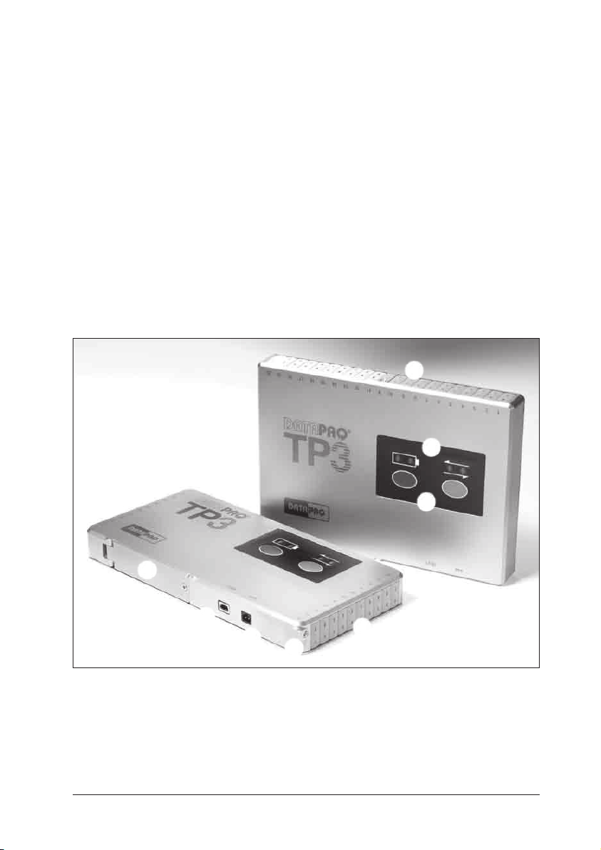
A
B
C
D
E
F
G
TP3 loggers: 10-channel narrow and 20-channel wide
A Thermocouple sockets.
B Battery and logger status LEDs
(p. 15).
C Stop/start buttons (p. 17).
D Battery compartment door (p. 22).
DATAPAQ TP3 Specifications and Operation 11
A
E USB communications socket
(p. 39).
F Charging socket (p. 21).
G Transmitter-aerial socket (for use
with TM21 telemetry system).
Page 12

• Ten or 20 thermocouple channels (depending on model size; see below)
for maximum data collection on each run.
• Can be specified for use with various thermocouple types (B, J, K, N, R,
S, T; see p. 14) and with analog inputs (current and /or voltage; see
p. 29) – or with a mixture of thermocouple types and/or analog inputs.
• Powered by standard alkaline AA batteries or by user-replaceable
rechargeable NiMH batteries; for high-temperature applications
involving logger operating temperatures (i.e. inside the thermal barrier) of up
to 110°C/230°F, can also be powered by non-rechargeable lithium
batteries. Any logger can use any battery-type interchangeably if
appropriate battery housings are used (available separately). See p. 17.
• Short sample intervals, to collect maximum data in minimum time
(p. 13) .
• High accuracy for compliance to tight specifications (see p. 14):
for type K thermocouples, ±0.3°C/0.5°F (above −100°C/−148°F);
for type N thermocouples, ±0.4°C/0.7°F (above 0°C/32°F).
• Data gathered by the logger but not yet downloaded (‘hot data’) is
protected by non-volatile memory or by software warning if reset is
attempted before download.
• USB and Bluetooth communication (p. 29).
• Hardwired telemetry (p. 55) or (if specified for use with optional
TM21 system) radio telemetry for monitoring in real time – both with full
analysis functions and alarms to warn the user if the process is out of
specification.
• Four LEDs to show the exact status of the logger’s activity and its batteries
(p. 15) .
• Start and stop buttons for easy user control (p. 17, p. 53).
• Rugged case and electronics allow operation in harsh environments of
dust, pressure and vacuum.
• Reset possible by start button alone, for speed and simplicity (p. 47).
Specifications
Narrow – 10-channel
TP3000A
Height
Width
Length
20.5 mm/0.8 in.
97 mm/3.8 in.
198 mm/7.8 in.
12 Specifications and Operation DATAPAQ TP3
Narrow – 20-channel
TP3300A
20.5 mm/0.8 in.
97 mm/3.8 in.
198 mm/7.8 in.
Wide – 20 -channel
TP3400A
20.5 mm/0.8 in.
124 mm/4.9 in.
177 mm/7.0 in.
Page 13

Thermocouples Available for a single thermocouple type, or for combinations of
up to three types: B, J, K, N, R, S, T (see specifications for each,
below).
Analog inputs:
Current
See p. 29.
Measurement range 4–20 mA.
Accuracy ±0.1% at 24°C/75°F.
Voltage
Measurement range 0–10 V.
Accuracy ±0.1% at 24°C/75°F.
Operating temperature
(of the logger itself)
Dependent on battery type:
Rechargeable −40°C to 70°C/−40°F to 158°F.
Alkaline −40°C to 55°C/−40°F to 131°F.
Lithium −40°C to 110°C/−40°F to 230°F.
Humidity range 0–100% non-condensing.
Operating pressure
(excluding limitations on
10−7 bar at 20°C to 20 bar at 110°C
1.5 × 10⁻⁶ psi at 68°F to 290 psi at 230°F
battery)
Real-time monitoring Hardwired (serial) telemetry via communications lead (p. 55),
or via Bluetooth (p. 32), as standard.
Radio (RF) telemetry via optional built-in transmitter.
Data capacity Over 3.6 million data-points in total, plus associated pre-trigger
data (see p. 54) and calibration data. This is sufficient for, e.g., 10
runs of 10 hrs with 10 probes and sample interval 5 sec. Using
fewer probes (see p. 43) increases the possible run-time.
Hot-data protection By non-volatile memory, and software warning if reset attempted
before download.
Logger reset By Insight (p. 41) or by start button (using previous reset
options) (p. 47).
Sample interval:
No telemetry
1
1–3 channels 0.1 s to 50 min.
4–9 channels 0.2 s to 50 min.
10 channels 0.3 s to 50 min.
11–20 channels 1 s to 50 min.
Hardwired telemetry
1–10 channels 1 s to 50 min.
11–20 channels 2 s to 50 min.
Radio telemetry
2
1–20 channels 2 s to 50 min. In Japan, 4 s to 50 min.
Data-collection start No trigger, Start button, Date and time, Rising temperature,
Falling temperature.
Pre-trigger data stored Yes (configurable; see p. 53).
Multiple runs Collect data from up to 10 runs before downloading (see p. 45).
Multiple events Up to 10 events (different probe selections, sample intervals and
trigger modes for different stages of a profile run; see p. 45).
Communications USB 2.0, Mini-B socket.
Bluetooth (p. 29) (not available in all countries).
PC/software compatibility See p. 37.
cont. >>
DATAPAQ TP3 Specifications and Operation 13
Page 14

Battery Interchangeable types, each in different battery housing (see
p. 17 ):
•NiMH rechargeable, 4 × 1.2 V (only Datapaq battery-packs
are suitable). For battery life, s
ee p. 21.
•Alkaline, 4 × AA 1.5 V (Duracell or other quality batteries
recommended). For battery life, s
ee p. 24.
•Lithium thionyl chloride non-rechargeable, 4 × AA 3.6 V,
for high-temperature use (only Datapaq battery-packs are
suitable). For battery life, s
ee p. 25.
Battery charger CH0 070 power-supply unit: input 90 –264 V AC, 50 –60 Hz,
400 mA. Must not be used if the ambient temperature is below
10°C/50°F or over 40°C/104°F.
USB power Logger is powered by USB when connected; no batteries are then
required (except when being reset for a non-telemetry run ; see
p. 41).
1
Intervals of 1 s and above can be set only in whole seconds.
2
Data applies to radio telemetry using a single transmission, i.e. no interleaving (see TM21 Radio-telemetry
System User Manual; or, in Insight’s Help system, select Menu Functions > Logger > Reset).
Specifications for Specific Thermocouple Types
Type B Type J Type K
Measurement
range
Accuracy *
(using sample
interval > 0.8 s)
Resolution 0.1°C/0.2°F 0.1°C/0.2°F 0.1°C/0.2°F
Socket color
(IEC 60584-3)
55°C to 1,815°C
131°F to 3,299°F
±3.0°C at 400°C
±1.0°C at 1,500°C
±5.4°F at 752°F
±1.8°F at 2,732°F
0°C to 800°C
32°F to 1,472°F
±0.3°C
±0.5°F
−190°C to 1,370°C
−310°F to 2,498°F
±0.5°C below −100°C
±0.3°C above −100°C
±0.9°F below −148°F
±0.5°F above −148°F
Gray Black Green
Type N Typ e R Type S
Measurement
range
Accuracy *
(using sample
interval > 0.8 s)
−190°C to 1,300°C
−310°F to 2,372°F
±0.5°C below 0°C
±0.4°C above 0°C
±0.9°F below 32°F
±0.7°F above 32°F
0°C to 1,760°C
32°F to 3,200°F
±1.0°C at 200°C
±0.8°C at 1,00 0°C
±1.8°F at 392°F
±1.4°F at 1,832°F
0°C to 1,760°C
32°F to 3,200°F
±1.0°C at 200°C
±0.8°C at 1,00 0°C
±1.8°F at 392°F
±1.4°F at 1,832°F
Resolution 0.1°C/0.2°F 0.1°C/0.2°F 0.1°C/0.2°F
Socket color
Pink Orange Orange
(IEC 60584-3)
14 Specifications and Operation DATAPAQ TP3
Page 15

Type T
Measurement
range
Accuracy *
(using sample
interval > 0.8 s)
Resolution 0.1°C/0.2°F
Socket color
(IEC 60584-3)
−196°C to 400°C
−321°F to 752°F
±0.5°C below −100°C
±0.3°C above −100°C
±0.9°F below −148°F
±0.5°F above −148°F
Brown
*
There will be an additional error of 0.01°C for every
1°C difference between the temperature at which
the logger is operated (i.e. the logger’s internal
temperature) and the temperature at which it was
calibrated. For more-detailed accuracy data, contact
Fluke Process Instruments.
Due to continuing product development,
specif ications are subject to change
without notice.
Logger LEDs
The logger is equipped with two sets of two LEDs:
• Ye l l ow and green/red show the status of the battery.
• Red and green show the status of the logger and its memory.
To see an animated demonstration of all the LED sequences: in Insight,
select Help > LED Sequences; or, in Insight’s Help system, select Introduction >
Logger LEDs.
Battery Status LEDs
Yell o w Green/Red Meaning
Off Off Battery has at least 20% of full charge (charger not
Flashing every
second
Off RED Battery charging.
Off GREEN Charging complete (charger connected).
Off Flashing RED
Double-flash
every second
Off Battery has 20% or less of full charge (charger not
once per second
Off Lithium batteries are being depassivated (see p. 27).
connected), or...
Charger is connected but logger is acquiring data (in which
case logger-status green LED will be flashing), or...
Fault with battery or logger.
connected).
Battery being preconditioned due to being too hot, too cold
or too deeply discharged (see p. 22).
DATAPAQ TP3 Specifications and Operation 15
Page 16

Logger Status LEDs
Red Green Meaning
Red and green LEDs each give 5
flashes, alternating with each other
Red and green LEDs flash
continuously, alternating with each
other, at sample interval *
Red and green LEDs continuously give
double-flash together, every 5 seconds
On Flashing at sample
Red and green LEDs flash together, at
sample interval *
Off Flashing at sample
Flashes 5 times Off Connection between communications lead and logger
Flashing every
5 seconds
2 quick flashes
every second
Flashing every
second
One flash Off Start button pressed during a profile run to mark an
*
Flashing interval will actually fall in range 0.5 –5 s.
interval *
interval *
Off Logger has data in memory which has not been
Off Logger too hot to start logging (after pressing start
Off Internal error. (Logger will power-off after 5 mins – or
Logger successfully reset.
Logger awaiting trigger (see p. 43) (in most
situations, except as below).
Logger awaiting start-button trigger for 2nd or
subsequent runs in multiple-run mode (see p. 45).
Logger awaiting trigger, but one or more of the
enabled input channels is open circuit.
All probes are above trigger temperature, and thus
data-recording cannot be triggered by rising temperature (or, if falling trigger is set, all probes are below
trigger point). Reset temperature trigger (see p. 43).
Logger acquiring data.
has been made.
downloaded. (Logger will power-off after 5 mins – or
after 30 mins if Bluetooth is on.)
button).
after 30 mins if Bluetooth is on.)
event (see p. 53).
Four-LED Sequences
When the logger is able to receive Bluetooth communication (p. 29),
each of the four LEDs will flash once in horizontal sequence, repeating every
20 seconds.
When green and red buttons are pressed, together, to turn off logger (see
below), all four LEDs flash together, once.
16 Specifications and Operation DATAPAQ TP3
Page 17

Start/Stop Button Actions
Action Results Notes
Press GREEN button
after data from previous
run has been
downloaded and/or
logger has been reset.
Press GREEN button
when logger contains
‘hot data’, i.e. data
which has not been
downloaded.
Press RED button. Stops logging. Data retained in memory. Logger
Press GREEN and
RED buttons together
and hold for 5 seconds.
Starts logging. If logger was not reset after
If in single-run mode or if in multiple-
run mode and 10 runs have been
performed (p. 45), logger powers
up (but will not start a new run or
delete data). If in multiple-run mode
and fewer than 10 runs have been
performed, logger starts logging.
Turn s logger off. All four LEDs
flash together, once.
previous run, the last reset
options (sample interval, probe
selection, etc.) are used as
default. In telemetry mode,
logger also starts sending data.
Each run of a multiple run will
be performed using the same
data-collection options, until the
logger is reset.
cannot be re started until data is
downloaded (unless in multiplerun mode, p. 45). Red LED
flashes every 5 seconds to warn
of data in memory. If in telemetry
mode, will also send ‘end of run’
signal to end real-time run.
Data retained in memory. The
previous reset options are
retained as current default.
It is possible to set the logger up so that use of the stop button is disabled during
a profile run. See p. 53.
Battery
Every TP3 logger can use three battery types interchangeably.
• NiMH rechargeable (see p. 21).
• Alkaline AA (see p. 23).
• Lithium non-rechargeable for high-temperature use (see p. 25).
Each type uses a different battery housing, identified by a different-colored label
(see below) which also shows the logger’s permitted operational temperature.
All types can be replaced by the user.
DATAPAQ TP3 Specifications and Operation 17
Page 18
The key differences between the three battery types, in use, are as follows.
NiMH Alkaline Lithium
Label on battery housing Green Blue Red
Logger’s operating
temperature (internal)
Rechargeable Yes No No
Battery life
(10 channels, sample interval 1 min.,
logger temperature 70–100°C/
158–212°F, no telemetry)
Charge level shown by Insight
(p . 19)
Special safety measures No No Yes (see p. 27)
Disposal (p. 34) Return to Fluke
−40°C to 70°C
−40°F to 158°F
200 hrs (between
charges)
(see p. 21)
Yes Yes No
Process Instruments
−40°C to 55°C
−40°F to 131°F
450 hrs
(see p. 24)
Recycling center Recycling center
−40°C to 110°C
−40°F to 230°F
500 hrs
(see p. 25)
(see also p. 28)
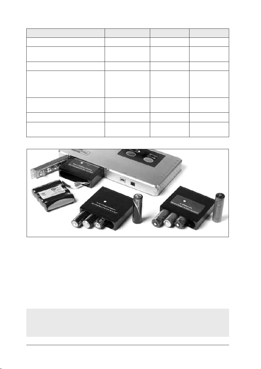
Interchangeable battery-packs and housings:
NiMH rechargeable (left, p. 21), alkaline (center, p. 23) and lithium (right, p. 25).
The logger automatically detects the type of battery in use, which prevents
damage to non-rechargeable batteries if the charger is connected by mistake.
To remove the battery housing from the logger (in order to replace with a
new one or to change the battery type in use), see p. 23.
For disposal of batteries, see p. 34.
When the communications lead is attached, the logger is powered via USB.
Batteries can be left in the logger, but they are not then required (except when the
logger is being reset for a non-telemetry run; see p. 41).
18 Specifications and Operation DATAPAQ TP3
Page 19

Battery Life
For a given battery type, battery life is affected by the following factors.
• Operating Temperature – Essentially, the higher the ambient
temperature the battery operates in, the shorter will be the life. Batteries
that operate for a large part of the process cycle at relatively low
temperatures will have a longer life than those that operate for the majority
of the process cycle at the maximum operating temperature.
• Sample Interval – The shorter the sample interval, the shorter will be the
battery life. This is because power is being consumed each time the logger
takes a reading. A short sample interval will achieve the maximum amount of
information, but this must be balanced against the greater battery charge
required.
• Bluetooth – Bluetooth communication causes extra battery drain, and
should be turned off (see p. 31) if not used.
• Operating with Radio Telemetry – Sending data to a receiver outside
the oven, furnace or kiln requires more power than that needed simply to
read and store the data.
Given the factors that can affect the life of a battery it is obviously difficult to
predict accurately. The LEDs on the logger will give the best indication of when
the battery is low. In the user’s own conditions, experience will quickly indicate
typical battery life, and a log should be kept for the first few runs, noting sample
interval and whether radio telemetry was used.
See the sections below on specific battery types for guideline battery-life data.
The Logger Reset dialog (p. 42) shows actual battery use: the time since
the battery was last charged or last changed.
Charge Level of Batteries
When the battery’s charge drops to 20% of the full level, this will be shown by
the logger LEDs (p. 15) .
For NiMH and alkaline batteries only... When connected to the PC, the
Insight software shows the logger’s battery-charge level as a percentage of full
charge, as follows:
• In the main Logger Reset dialog (p. 41).
• When using wizards which reset the logger.
• During communications setup (p. 40).
• When using the Real Time Tool dialog during Bluetooth telemetry (p. 32)
or during use of the optional TM21 radio-telemetry system.
DATAPAQ TP3 Specifications and Operation 19
Page 20

For alkaline batteries, the battery-charge level displayed by Insight will be valid
only if Duracell or other quality batteries are fitted. Using inferior batteries may
cause misleading percentages to be shown.
Battery Voltage
The logger records the battery voltage during a profile run. This is then
downloaded to be stored in the paqfile and can be displayed on screen alongside
the temperature profile. See p. 53.
Auto Power-off
To save battery life, the logger will power-off automatically in the following
situations.
• The communications lead is unplugged when the logger does not contain
data which has not been downloaded (e.g. after a data-download) and the
logger has not been reset.
• The PC is powered down while the logger is connected to it.
• The logger contains data from a previous run which has not been
downloaded (the logger-status red LED will be flashing every 5 seconds), and
has been in this state for 5 minutes (or for 30 mins if Bluetooth is turned on;
see p. 29). Note that:
○ The power-off will not cause this data to be lost.
○ The data will continue to be marked as ‘not yet downloaded’, reducing
the chance of it being accidentally deleted later.
• The logger-status LEDs have been indicating an error (red LED will be
flashing every second) for 5 minutes.
• The logger has Bluetooth turned on but there has been no Bluetooth
communication for 30 minutes.
When the communications lead is attached, the logger is powered via USB (see
p. 18) and will not automatically power-off.
The logger will automatically power-up in the following situations.
• The communications lead (connected to a powered PC) is plugged in. The
logger is then ready to communicate with the PC.
• The start button is pressed. The logger will then resume the mode that it
was in when it powered-off, e.g. not-yet-downloaded data will continue to
be protected from accidental deletion.
20 Specifications and Operation DATAPAQ TP3
Page 21

NiMH Rechargeable Batteries
The logger can use a pack of four rechargeable 1.2 V nickel-metal-hydride
(NiMH) cells. These are suitable for applications where the logger’s operating
temperature (i.e. the temperature of the logger itself) does not exceed
70°C/158° F. Only Datapaq battery-packs are suitable.
For the service life and replacement of the battery, see p. 22.
Life of NiMH Batteries
The data below can serve as a guide – though the values given are no more than
an indication of the battery life that can be expected. See p. 19 for general
considerations that affect actual battery life.
No. of
Channels
10 3 25°C/77°F – –
10 3 70°C /158°F – 150
10 60 25°C/77°F 280 –
10 60 70°C /158°F 200 –
10 180 25°C/77°F – –
10 180 70°C /158°F – 240
20 3 25°C/77°F – –
20 3 70°C/158° F – 110
20 60 25°C/77°F 200 –
20 60 70°C/158° F 150 –
20 18 0 25°C/77°F – –
20 18 0 70°C/158° F – 160
Sample
Interval
(sec.)
Logger
Temperature
Battery Life (hrs)
No Radio
Telemetry
Radio
Telemetry Used
Charging NiMH Batteries
Recharge the battery as follows.
1. Plug the charger into the electricity supply.
2. Plug the charger lead into the charging socket on the logger.
A full charge is typically delivered in less than 2 hours, maximum about 3 hours.
Indication of battery/charging status is provided by colored LEDs on the logger
(see p. 15).
The charger must not be used if the ambient temperature is below 10°C/50°F
or over 40°C/104°F.
DATAPAQ TP3 Specifications and Operation 21
Page 22

The logger intelligently monitors the battery, ensuring it is never overcharged.
Thus, by leaving the charger connected to the logger, the logger will always be on
charge and ready for use. This will not damage the battery or reduce its service life.
Note that the logger will not charge while collecting data. The charger can be
connected to the logger while logging, but charging will stop as soon as data-
collection starts.
New batteries – or ones which have been unused for several months – should
be charged for 24 hours before use.
NiMH batteries discharge slowly even when not in use and will need
charging if left for more than three weeks.
WARNING
If the logger is not in regular use, the battery should be charged at least
every 3 months. If this is not done, the battery may drain to a level where it
cannot successfully be recharged.
Where batteries are too cold (below 0°C/32°F), too hot (over 45°C/113°F) or
too deeply discharged, they must be preconditioned before fast charging can
begin. Pre-conditioning (slow charging) occurs automatically if it is required, and
is shown by the battery status LEDs (steady yellow + flashing red). If the battery
is still being pre-conditioned after 5 hours, there may be a fault; contact Fluke
Process Instruments.
Replacing NiMH Batteries
WARNING
Use only the correct Datapaq battery-pack. Using unapproved batteries can lead to
battery-leakage producing toxic fumes and causing respiratory irritation and
chemical skin burns. Never use a damaged battery-pack (e.g. with split in
heatshrink covering, wires detached, etc.).
Keep battery-packs clean and dry. Clean dirty connectors with a dry, clean cloth.
Do not disassemble or crush battery-packs.
Do not put battery-packs near heat or fire, nor in sunlight.
The logger employs non-volatile memory, so – even when the battery is
removed and replaced – stored data will not be lost.
Service life of the rechargeable NiMH battery is up to about 500 charge/
discharge cycles.
22 Specifications and Operation DATAPAQ TP3
Page 23

The battery-pack is easily replaced by the user, as follows.
1. Ensure the logger is powered off: press green and red buttons together,
and hold for 5 seconds.
2. On the side of the logger, remove the single screw securing the battery-
compartment door. See photo, p. 11.
3. Carefully squeeze the metal clips
on the side of the battery-pack
connector and pull the two
halves of the connector apart
(A, see photo).
4. Turn the logger to let the old
battery-pack slide out of its
housing, and dispose of the pack
appropriately (see p. 34).
WARNING
Do not pull or hold battery-packs (whether old or new) by their connector wires.
Only Datapaq NiMH battery-packs are suitable.
5. Connect the new battery-pack and slide it into the battery housing. Take
care not to damage the connector wires nor to leave any debris in the
battery compartment as this could cause malfunction.
6. Position the wires so that the connector lies flat on the end of the
battery-pack (A).
7. Secure the battery-compartment door with its screw.
8. Charge for 24 hours before first use (see p. 21).
A
To remove the battery housing (in order to replace with a new one or to
change the battery type in use), proceed as follows.
1. Open the battery-compartment door and remove the battery-pack, as above.
2. Pull out the battery housing.
3. Insert the new battery housing with its label towards the front face of
the logger, ensuring the internal connector has engaged.
4. Fit the battery-pack and secure the battery-compartment door as described
above.
Alkaline Batteries
If the correct battery housing is fitted (see p. 17), the logger can use four
alkaline AA 1.5 V. cells. Fluke Process Instruments recommends the use of
Duracell or other quality batteries. These are suitable for applications where
DATAPAQ TP3 Specifications and Operation 23
Page 24

the logger’s operating temperature (i.e. the temperature of the logger itself)
does not exceed 55°C/131°F.
For alkaline batteries, the battery-charge level displayed by Insight (p. 19) will
be valid only if Duracell or other quality batteries are fitted. Using inferior batteries
may cause misleading percentages to be shown.
Life of Alkaline Batteries
The data below can serve as a guide – though the values given are no more than
an indication of the battery life that can be expected. See p. 19 for general
considerations that affect actual battery life.
No. of
Channels
10 3 25°C/77°F – –
10 3 70°C /158°F – 150
10 60 25°C/77°F – –
10 60 70°C /158°F 450 –
20 3 25°C/77°F – –
20 3 70°C /158°F – 210
20 60 25°C/77°F – –
20 60 70°C /158°F 370 –
20 180 25°C/77°F – –
20 180 70 °C /158 °F – 420
Sample
Interval
(sec.)
Logger
Temperature
Battery Life (hrs)
No Radio
Telemetry
Radio
Telemetry Used
Replacing Alkaline Batteries
Carry out as follows.
1. Ensure the logger is powered off: press green and red buttons together,
and hold for 5 seconds.
2. On the side of the logger, remove the single screw securing the battery-
compartment door. See photo, p. 11.
3. Turn the logger to let the old batteries slide out of the housing, one at a
time, and dispose of them appropriately (see p. 34).
4. Slide new batteries into the housing, one at a time, observing polarity.
Check that you are using the correct battery type for the battery housing
fitted. If in doubt, remove the housing (see p. 23) and check the label on it.
24 Specifications and Operation DATAPAQ TP3
Page 25

5. Secure the battery-compartment door with its screw.
To remove the battery housing from the logger (in order to replace with a
new one or to change the battery type in use), see p. 23.
Lithium Batteries
For high-temperature applications, if the correct battery housing is fitted (see
p. 17), the logger can use four lithium thionyl chloride non-rechargeable AA
3.6 V cells. These are suitable for applications where the logger’s operating
temperature (i.e. the temperature of the logger itself) does not exceed
110°C/230°F.
WARNING
Only lithium batteries supplied by Datapaq, BP0021, are suitable for use with the
TP3 logger.
Life of Lithium Batteries
The data below can serve as a guide – though the values given are no more than
an indication of the battery life that can be expected. See p. 19 for general
considerations that affect actual battery life.
No. of
Channels
10 3 25°C/77°F – –
10 3 10 0 °C/212°F – 370
10 60 25°C/77°F – –
10 60 10 0 °C/212°F 500 –
10 18 0 25°C/77°F – –
10 18 0 100 °C/212° F – 480
20 3 25°C/77°F – –
20 3 100 °C/212° F – 200
20 60 25°C/77°F – –
20 60 100 °C/212° F 500 –
20 180 25°C/77°F – –
20 180 100°C/212° F – 500
DATAPAQ TP3 Specifications and Operation 25
Sample
Interval
(sec.)
Logger
Temperature
Battery Life (hrs)
No Radio
Telemetry
Radio
Telemetry Used
Page 26

Replacing Lithium Batteries
When the logger ceases to operate due to exhausted batteries, they should be
immediately removed and disposed of.
WARNING
Lithium batteries – Fire, explosion and severe burn hazard
Lithium batteries are potentially dangerous and require great care in handling
and storage. You must read the section ‘Handling Lithium Batteries’ (below) and
the Safety Data Sheet supplied with the batteries.
Remove and replace the batteries as follows.
1. Select a clean, dry, non-conductive work surface; do not use a metallic
surface or anti-static matting. Take off any conductive jewellery and put it
out of the way. Wear eye protection.
2. Ensure the logger is powered off: press green and red buttons together,
and hold for 5 seconds.
3. On the side of the logger, remove the single screw securing the battery-
compartment door. See photo, p. 11.
4. Turn the logger to let the old batteries slide out of the housing, one at a time.
Ensure that the battery terminals cannot be short-circuited in any way – to each
other, to the logger or to any tools. There is risk of explosion.
5. Place each battery separately on the work surface, maintaining good
separation between them. Mark the work surface area into which they are
placed, in order to identify them as the old batteries. Ensure the battery
compartment is clean and dry, and carefully wipe the battery contacts with a
dry lint-free cloth or tissue with attention to the contact area. Do not bend
or distort the contacts.
6. Remove the new batteries from their protective UN-compliant packaging,
and retain this for later use.
7. Carefully install each new battery, one at a time, into the battery housing.
Check that you are using the correct battery type for the battery housing
fitted. If in doubt, remove the housing (see p. 23) and check the label on it.
Observe the polarity of the batteries and of the contacts within the
battery compartment.
Ensure that the battery terminals cannot be short-circuited in any way – to each
other, to the logger or to any tools. There is risk of explosion.
26 Specifications and Operation DATAPAQ TP3
Page 27

Always replace all of the batteries at the same time.
Never use batteries other than those supplied by Datapaq.
Do not mix different types of Datapaq battery, nor batteries of any other type;
this could lead to an explosion.
8. Carefully place the old batteries one at a time into the empty packaging. Do not
allow them to be short-circuited. See below for disposal of lithium batteries.
9. Re-check that batteries are installed with correct polarity, then secure the
battery-compartment door with its screw.
10. Datapaq batteries must be depassivated before they are used for the first
time. This takes place automatically after placing them in the logger, as
follows.
a. Yellow LED produces two rapid flashes every second.
b. After 20 minutes, yellow LED stops flashing.
c. Logger is ready for use.
To remove the battery housing from the logger (in order to replace with a
new one or to change the battery type in use), see p. 23.
Handling Lithium Batteries
WARNING
Lithium batteries – Fire, explosion and severe burn hazard
Lithium batteries are potentially dangerous and require great care in handling
and storage.
Do not short-circuit • Do not attempt to recharge •
•
Do not reverse-connect • Do not open batteries •
•
Do not expose battery contents to water •
•
Do not solder anything to the battery • Do not incinerate •
•
Do not mix cells • Do not leave discharged cells in the logger •
•
These instructions must be carefully read in full, and understood, by any person
likely to handle, replace or dispose of lithium thionyl chloride batteries.
Do not open, crush or deform the battery cells. If the lithium metal within the
cell is exposed to the air and moisture, an explosion or fire may result. The
contents are flammable, corrosive and extremely irritating to the lungs and
respiratory system. Lithium metal and thionyl chloride cause chemical burns on
contact with skin.
The Datapaq inorganic lithium thionyl chloride batteries will, when used
correctly, provide a safe and dependable source of power. They represent the
only current battery technology that can meet the demands of high-temperature
operation. Unlike more conventional batteries, lithium cells contain flammable
materials, and consequently safety precautions must be taken during transport,
DATAPAQ TP3 Specifications and Operation 27
Page 28

storage, handling and disposal. If lithium batteries are mistreated there is a risk
of leakage of the flammable contents or an explosion resulting in a fire.
Each battery is marked as follows:
Warning : Fire, explosion, and severe burn hazard.
Do not recharge, disassemble, heat above 150°C , incinerate or expose contents
to water.
To meet the requirements of the Control of Substances Hazardous to Health
Regulations 2002 (COSHH), each battery consignment includes a Safety Data
Sheet. Any person likely to handle, replace or dispose of lithium thionyl chloride
batteries must be made aware of this data sheet. The sheet should be passed to
your Health and Safety officer for future reference; extra copies are available
from Fluke Process Instruments. The sheet contains details of first-aid and
firefighting procedures.
Transport, and Storage Before Use
Due to the flammable content, lithium thionyl chloride batteries are classified as
Dangerous Goods under UN transport regulations. The packaging used to
supply the cells is UN-compliant and is labeled accordingly. The batteries must
be transported only within this packaging.
Packages containing lithium batteries should be handled with care. Rough
handling may result in batteries becoming damaged which may cause leakage,
explosion or fire.
On receipt do not remove the lithium batteries from their UN-compliant
packaging. Store the batteries within their original packaging until required.
The lithium batteries should be stored apart from all other flammable materials.
The storage area should be cool, dry, ventilated and weatherproof. Temperatures generally should be below 35°C/95°F. Do not store next to radiators or
boilers or in direct sunlight. Avoid storage temperatures above 75°C/167°F.
Disposal of Used Lithium Batteries
The used batteries should be disposed of as soon as possible. Even though no
longer capable of powering the logger, the batteries remain flammable and have
sufficient energy to cause a fire or to explode if short-circuited. The
UN-compliant packaging should thus be used to store the used batteries after
removal from the logger and at disposal. Under the European Union Batteries
and Accumulators Directive, the used batteries which are removed from the
logger by the user should be disposed of at an appropriate recycling center. Do
not dispose of in fire and do not incinerate. Datapaq BP0021 lithium
batteries do not contain mercury, cadmium or any other heavy metal or other
hazardous material according to EU Directives 91/157/EEC and 93/86/EEC.
28 Specifications and Operation DATAPAQ TP3
Page 29

Analog Inputs
In addition to storing data from thermocouple input, the TP3 can be specified to
support the recording of current and/or voltage data to allow other types of
sensor to be used. For measurement ranges and accuracy, see p. 13.
Such analog input is made via one or more of the logger’s numbered sockets
(when fitted, colored white), relevant channel numbers being shown on a label
on the rear of the logger. For each analog input on the logger, a white plug is
provided for connection to the chosen sensor device.
WARNING
Incorrect connection to the current and/or voltage sockets may cause serious
damage to the logger. Always check the label carefully to ensure that input cables
are connected to the correct channels.
Data from the analog-input channels is displayed by Insight as a custom unit on
the right-hand axis of the graph window. To set up custom units in Insight,
select Tools > Options > Units, and click Help for a full explanation.
Analogue inputs support the same sample intervals as thermocouples (see p. 13).
Analog inputs can be calibrated by Fluke Process Instruments, and this generates a
separate calibration certificate from that produced by calibrating thermocouple
inputs (see p. 33). Unlike thermocouple inputs, however, the logger does not
store the results of analog-input calibration, and thus: a calibration certif icate
cannot be printed by the user; a logger correction factor f ile for analog inputs
cannot be produced.
Bluetooth Communications
Bluetooth communication is not available in all countries.
Where unavailable, Bluetooth options in Insight will be greyed out.
As an alternative to using its communications lead, the logger can use Bluetooth
to communicate with the PC. This can be used for:
• Resetting the logger (p. 41).
• Downloading data from the logger to the PC (p. 48).
• Short-range wireless telemetry (see below).
• Downloading diagnostic information for troubleshooting (see p. 64).
DATAPAQ TP3 Specifications and Operation 29
Page 30

The reliable transmission range will vary but will typically not exceed 5 m, and
reception will not normally be possible from a logger inside a thermal barrier.
Bluetooth communication will not operate if the logger’s temperature is
above 85°C/185°F.
The logger will power-off automatically if Bluetooth is turned on (see below) but
there has been no Bluetooth communication for 30 minutes.
Bluetooth communication causes extra battery drain, and should be turned off (see
p. 31) if not used.
The TP3 logger is configured by default to be ready to use Bluetooth
communication. All that is necessary (as with any Bluetooth device) is to pair it
with the PC with which it will communicate. Thereafter, the operations listed
above can be performed without connecting the communications lead between
logger and PC. If Bluetooth is turned on but the communications lead is
connected, the lead (not Bluetooth) will be used preferentially.
Pairing
The logger and PC must be paired as two Bluetooth devices before
communication can take place between them. For PCs without built-in
Bluetooth support, it will be necessary to fit a Bluetooth adapter (dongle) to a
spare USB port; if using the adapter for the first time, follow its driverinstallation procedure.
Most available Bluetooth adapters are suitable – but NB that the adapter must be
Bluetooth ‘Classic’; adapters which are ‘low energy’, ‘LE’ or ‘Smart’ only (and are
not Classic) are not suitable.
Ensure that the logger is not connected to the PC with the communications lead, then
proceed as follows (details may vary, depending on the Windows version in use).
1. Ensure that Bluetooth is enabled on your PC by checking for the icon in
your Windows system tray (notification area), usually at the bottom right of
your Windows desktop: right-click it, and select ‘Open Settings’ to open the
Bluetooth Settings dialog. Ensure the following settings:
○ Uncheck ‘Allow Bluetooth devices to find this computer’ (if you wish to
prevent unauthorized connection to your PC).
○ Check ‘Allow Bluetooth devices to connect to this computer’.
Click ‘OK’ to close the dialog.
2. In Insight, select Logger > Setup to display the Communications Setup dialog
(see p. 40). Click ’Detect’, and wait until Insight recognizes and lists
suitable nearby loggers. (Loggers shown in red are those previously used
30 Specifications and Operation DATAPAQ TP3
Page 31

and/or too far away. To remove such a logger from the list, right-click on its
name and click Remove on the popup.)
3. Select the name of the logger in the ‘Bluetooth’ section of the dialog, click
the ‘Test’ button in the ‘Logger’ section, and the logger name will be
displayed there to confirm that communication is possible with that logger.
Clicking the ‘Diagnostic’ button should expand the dialog to show current
probe information and other data (p. 40).
4. Click ‘OK’ to close the dialog.
The logger and PC are now paired and ready to communicate.
Troubleshooting
In case of problems with establishing Bluetooth communication, try the following.
• Move the logger closer to, or further away from, the PC. If the logger’s
name is shown in red in the Communications Setup dialog, the logger is too
far away.
• If using a Bluetooth adapter, unplug and re-insert it.
• Unplug any devices attached to USB 3 ports (active USB 3 ports can
interfere with Bluetooth).
• Restart the logger (see p. 61).
More Than One Logger
When Bluetooth communication is initiated (e.g. by starting a logger reset), and
more than one Datapaq Bluetooth logger is present, Insight will display the
Select Logger dialog with a list of available loggers and their serial numbers.
Select the chosen logger and then click ‘OK’; clicking ‘Cancel’ will cancel
communication.
Turning Bluetooth On and Off
By default, as soon as pairing has been achieved (see above), Bluetooth is turned
on in the logger, but, under the following conditions, it will automatically be
turned off:
• When the logger and PC are connected by communications lead. Thus will
be turned off when hardwired telemetry (p. 55) is in use.
• When the logger is collecting data and storing it in memory.
• When radio-telemetry is in use.
When the logger is able to receive Bluetooth communication, each of the four
LEDs will flash once in horizontal sequence, repeating every 20 seconds.
DATAPAQ TP3 Specifications and Operation 31
Page 32

Bluetooth communication causes extra battery drain, and should be turned off,
as follows, if not used.
1. Ensure the logger is connected to the PC using the communications lead.
Logger and PC must be connected by the communications lead in order
to turn Bluetooth either on or off.
2. In Insight, select Logger > Setup to display the Communications Setup dialog.
3. Click ‘Test’, The logger name will be displayed and the ‘Bluetooth’ button
will be enabled.
4. Click ‘Bluetooth’ to display the Bluetooth Setup dialog.
5. A message below the ‘Check Status’ button will show whether Bluetooth is
currently enabled or disabled (turned on or off) – or whether the logger and
PC are not connected by cable. Click the button if necessary.
6. Click ‘Enable Bluetooth’ (to turn on) or ‘Disable Bluetooth’ (to turn off) as
required, and a message will confirm the change.
Bluetooth Telemetry
Temperature-profile data gathered by the logger can be passed directly to the
PC, in real time, by using Bluetooth communications. Because good Bluetooth
reception cannot usually be achieved with a logger inside a thermal barrier (see
p. 30), the logger will normally be outside the thermal process, with
thermocouples trailing from the oven/furnace/kiln to the logger. The process of
running a profile is thus as for hardwired telemetry (p. 55) – and the major
benefit of Bluetooth telemetry is to isolate the logger from the PC and thereby
avoid earth-loop problems.
The procedure follows that used for hardwired telemetry (see p. 55) except that:
• Logger reset (p. 41) must be carried out using Bluetooth (i.e. do not
connect the logger to the PC using the communications lead). The
‘Bluetooth Telemetry’ option is then available to be selected in the Logger
Reset dialog.
• While a run is in progress, you may use the Real Time Tool dialog to
check the integrity of data-packets as they are received, as well as the status
of the logger (click on the toolbar, or select View > Real Time Tool).
Data can be collected from only one logger at a time. If more than one logger is
present and gathering data, choose which logger’s data to gather and display in
real time by selecting Logger > Logger Listen Mode; this displays the Select
Logger dialog (see p. 31).
Wireless telemetry over greater ranges, and/or involving use of a thermal
barrier, will require the TM21 radio-telemetry system (available separately).
32 Specifications and Operation DATAPAQ TP3
Page 33

Over-temperature Protection
The logger and the Insight software work together to reduce the likelihood of
damage occurring due to the logger’s internal temperature being too high. (For the
logger’s operating-temperature range, see p. 13.)
• Insight can be instructed to show a warning message if a reset is
attempted (p. 41), or to prevent a reset, while the logger is above a
specified temperature (default 45ºC/113ºF); see p. 53.
• If logging is started without resetting the logger using Insight (i.e. by simply
pressing the start button and thus using the previous reset options; see
p. 47), the logger will not start logging if its internal temperature is above
45ºC/113ºF. The logger-status red LED will show 2 quick flashes every second.
• If the logger’s internal temperature exceeds 75ºC/167ºF (when fitted with
NiMH or alkaline battery) or 115ºC/239ºF (when fitted with lithium battery),
it shuts down, preserving data already collected. When the data is
downloaded, Insight will give a warning that this has happened.
The logger records its internal temperature during a profile run. For access to this
data, see p. 53.
To check the logger’s current internal temperature when connected to a PC running
Insight, select Logger > Setup and click ‘Diagnostic’ (p. 39). The temperature is
also displayed in the Reset dialog (p. 41).
Testing and Calibration
It is recommended that the logger is tested and calibrated by Fluke Process
Instruments at least once a year. The calibration procedure comprises:
• Inspection of the logger, externally and internally.
• Battery- and charge-testing.
• Heat-cycle test of up to 14 hours in the ovens of Fluke Process Instruments.
• Stability testing, using a stable temperature source and varying ambient
temperatures.
• Calibration and updating of the logger’s firmware.
• Issue of certificate, which can be traced back to UKAS or NIST calibration
standards.
To calibrate your logger, please return it to the Service Department at Fluke
Process Instruments (see p. 63).
For full certification and traceability, calibration data is stored in each logger for
instant access by Fluke Process Instruments engineers. To print a calibration
certi ficate for a logger, in Insight select File > Print Calibration Certificate (NB not
available with all Insight products), and then choose whether to print a certificate for:
DATAPAQ TP3 Specifications and Operation 33
Page 34

• The logger which was used to create the currently displayed paqfile
(temperature profile). or
• The logger (if any) which is currently connected to the PC.
For maximum accuracy, Insight can use the logger’s calibration data to create a
logger correction factor file which can be applied to downloaded
temperature-profile data (NB not available with all Insight products). The file may
be created from calibration data which is:
• Entered manually, or
• Contained in the logger, or
• Contained in a paqfile.
To create a logger correction factor file, run the Logger Correction Factor
Wizard (select File > New > Logger Correction Factors). To be prompted to
apply a correction factor file whenever data is downloaded, select Tools >
Options > Logger, and check ‘Prompt for correction factors when downloading’.
Even without creating a logger correction factor file, the logger can be set to
apply logger correction to collected data automatically every time data is
downloaded. Connect the logger to the PC, and in Insight select Tools >
Options > Logger, and check ‘Automatically apply logger correction when
downloading’. (NB not available with all Insight products.)
For a full description of logger correction factors, see ‘Correction Factors’ in Insight’s
Help system.
To carry out your own basic testing of the operation of the logger and its
thermocouples, see p. 62.
Disposal of Batteries and Loggers
Always adhere to the applicable statutory regulations for recycling and waste
disposal. For details of recycling Fluke Process Instruments products within the
European Union, see www.fluke.com.
Under the European Union Batteries and Accumulators Directive,
used alkaline and lithium batteries which are removed from the
logger by the user should be disposed of at an appropriate recycling
center. For additional information on handling and disposing of lithium
batteries, see p. 27.
Under the European Union WEEE Directive, users should return all
NiMH batteries and all loggers (whether or not containing
batteries) to Fluke Process Instruments for disposal at the end of their
useful life.
34 Specifications and Operation DATAPAQ TP3
Page 35

Restrictions on Use
The following general considerations apply to use of the logger
and its associated equipment. For reasons of health and safety,
and to avoid harm or damage to the logger, to other equipment
and to the environment, always observe the following
restrictions and cautions.
For the logger’s specifications, see p. 11.
• The logger is not approved for use in potentially-explosive
atmospheres as defined by the EU ATEX directives. Do not use the
logger in such atmospheres: there is risk of major injury or death.
• It is essential to use the logger with the correct Datapaq thermal
barrier for your individual process, as supplied and approved by Fluke
Process Instruments. Failure to use the appropriate approved barrier, or
use in an unapproved manner (e.g. using above the specified temperature,
or for longer than the specified time, or with insufficient opportunity for
adequate cooling between profile runs), can cause catastrophic damage to
the data logger or to other equipment, and can endanger health, or may
lead to major injury or death. In particular, exceeding the logger’s
specified temperature range for any length of time may cause battery-
leakage producing toxic fumes and leading to respiratory irritation and
chemical skin burns. For the same reasons, never use a damaged thermal
barrier.
• Ensure that all dimensions of your logger/barrier/accessory assembly are
such that it will fit comfortably within the oven through all stages of
the process. Pay particular attention to handles, catches, etc., and to
trailing thermocouples. Failure to do this can cause the assembly to jam in
the oven with consequent overheating and potentially-severe damage to
the equipment. Resultant battery-leakage, and the process of recovering
the equipment, may cause skin burns and respiratory irritation.
• Batteries:
○ If using rechargeable batteries (see p. 17), use only the Datapaq
mains battery charger supplied with your logger. Using a charger
which is not approved by Fluke Process Instruments for use with
your logger could cause major injury or death.
○ Do not charge the battery in a wet environment, e.g. outside. This
could cause major injury or death.
○ Always use the correct Datapaq batteries (see p. 17). Using with
unapproved batteries may cause battery-leakage producing toxic
fumes and leading to respiratory irritation and chemical skin burns.
Never use a damaged battery-pack (e.g. with split in heatshrink
covering, wires detached, etc.).
cont. >>
DATAPAQ TP3 Specifications and Operation 35
Page 36

○ First plug the battery charger into the mains, i.e. before
connecting the logger.
○ Charge batteries only within temperature range 5 – 45 ° C / 41–113 ° F
(mains charger) or 0–85°C/32–185°F (PC’s USB port).
○ Keep battery-packs clean and dry. Clean dirty connectors with a dry,
clean cloth.
○ Do not disassemble or crush battery-packs.
○ Do not put battery-packs near heat or fire, nor in sunlight.
○ If not used for an extended period, remove battery-pack from logger
to prevent battery-leakage and resultant damage.
• Do not use the logger, or other Datapaq equipment, in humid/wet
process environments or corrosive atmospheres unless specifically
approved for such use by Fluke Process Instruments. Damage to the
equipment may result.
• Never connect thermocouples to mains electricity, nor allow
thermocouples to touch an oven’s heating elements. This could cause
major injury or death.
• Take care when handling thermocouple cables to avoid accidental damage
to the eyes by sharp thermocouple-tips.
• Use PTFE thermocouples only within their approved temperature
range. Use at higher temperatures produces irritant toxic fumes. See the
dedicated User Manual for your Datapaq Tracker system.
• Never carry the logger by holding the attached communications
lead or thermocouples. This can lead to injury by dropping the logger
onto your body, and may damage the lead, thermocouples or sockets.
• On removal from the oven, the thermal barrier and logger will be
hot enough to burn skin – even though their temperature will not be
apparent. Use protective gloves.
• Do not remove the logger from the thermal barrier by tipping it out of
the barrier. This can lead to injury by dropping the logger onto your
body, and may damage the logger.
• The user must on no account attempt any disassembly or repair
of the logger (other than to replace batteries, p. 17). Any such attempt
risks battery-leakage and may cause skin burns and respiratory irritation,
and will invalidate any existing warranty or service agreement with Fluke
Process Instruments. For information on the Datapaq Service
Department, see p. 63.
36 Specifications and Operation DATAPAQ TP3
Page 37

Using the Logger with
Insight Software
See your dedicated Datapaq Tracker system manual for full details on:
• Choosing appropriate thermal barriers and thermocouple probes.
• Installing the logger into the barrier.
• Conducting a temperature-profile run of your process.
Before the logger is used for the first time, you must:
1. Install Insight software (see below).
2. Establish communication between the logger and the computer/software
(p. 39).
Before each profile run, you will:
3. Reset the logger to prepare it to receive fresh data (p. 41).
After the logger/barrier assembly is recovered from the oven /furnace/kiln, you
will then:
4. Download the data from the logger (p. 48).
These stages are described below.
Installing/Removing Insight
Datapaq Insight used with the TP3 logger requires the following minimum
computer specification.
• 1 GHz processor.
• 2 Gb RAM.
• Monitor resolution 1024 × 768, 256 colors.
• 100 Mb free hard disk space.
• DVD drive.
• 1 free USB port.
• Microsoft Windows™ Vista (32-bit only), 7, 8, 10 or above.
• Microsoft Internet Explorer 4 or above.
The TP3 logger operates only with Datapaq Insight v.8.0 and above.
DATAPAQ TP3 Using Insight Software 37
Page 38

Installation
Ensure you are logged into Windows in Administrator mode.
For most systems, installation will start automatically on placing the Insight DVD
in the drive. (If installation does not start, click the Windows Start button and
select Run; browse to your DVD drive, and run Setup.exe.) As part of the
installation, you can choose PDFs of Datapaq user documentation to be copied
to your PC for rapid on-demand viewing through Insight.
Follow the on-screen instructions. You will need your license number to hand,
which is to be found on:
• Your license agreement.
• The outside of the DVD case.
• The outside of the system packaging.
Insight’s link with the logger must also be made while Windows is in Administrator mode, and it is thus best to do this now, as part of the Insight installation:
connect the logger to the PC and follow the procedure under ‘Communications
Setup’ (below). Once this has been done, an operator will be able to use Insight
with the logger connected to the PC without being in Administrator mode.
Upgrading
It is not necessary to remove an existing version of the software before
installing a new one. Settings and data files used with the current installation will
be maintained.
Removal
Use the standard procedure for your Windows version, e.g.
• In Windows 7 – Start button > Control Panel > Programs and Features, and
double-click Datapaq Insight.
• In Windows 10 – Start button > Settings > System > Apps & features, and
click Datapaq Insight.
Help System
Full details on using the Insight software are contained entirely within its online
Help system: access this by clicking Help, and then Contents, on Insight’s main
menu. Then, within Help, click on Contents headings and topics to expand and
read them.
38 Using Insight Software DATAPAQ TP3
Page 39

You may also click the Help button in any dialog – or press the F1 key – to bring
up help information relevant to the task being performed.
Communications Setup
After Insight has been installed, it is necessary to establish communication
between the data logger and the PC, as follows.
By default, only one logger at a time can be connected to the PC and it is not
possible to connect simultaneously more than one logger to different USB ports on
the PC and then to choose which logger to use (but see p. 58 for use of
multiple loggers). (Bluetooth communication does permit switching between multiple
loggers; see p. 31.)
1. Using the communications lead supplied, connect the logger to a free USB
port on the PC (to minimize communications problems, connect the lead
first to the PC and then to the logger). The red LED on the logger should
flash five times to confirm that the connection between the communications
lead and the logger has been made.
If the PC is having a Datapaq logger connected for the first time, Windows
will display a ‘Found New Hardware’ message and the PC is then ready to
work with the logger. If any warnings are displayed about driver-signing,
confirm them (Datapaq drivers have been tested, and were installed when
Insight was installed).
In case of problems in establishing communication, see p. 61.
2. On the Insight software’s menu bar, select Logger > Setup to open the
Communications Setup dialog.
3. Click Test .
If the logger is detected, its type and the port to which it is connected are
displayed.
SHORTCUT
Pressing F4 on the keyboard opens the Communications Setup dialog, tests for
communication with a logger, and displays the logger type and other data
(equivalent to clicking Test in the dialog).
For more information on the logger in use, click the Diagnostic button which
now appears. Additional data shown covers firmware version, maximum
permitted internal logger temperature, battery charge status, serial number and
temperature recording range. Current temperature of the probes (updated
every 5 seconds) is also shown – or open circuit (*OC*) if no probe is attached;
DATAPAQ TP3 Using Insight Software 39
Page 40

the temperature of the thermocouple cold junction is effectively the current
internal temperature of the logger.
The Communications Setup dialog for the TP3 logger, with Diagnostic section expanded.
For Bluetooth options, see p. 29.
It is advisable at this stage to set the frequency of the local electricity supply
within Insight. See p. 53.
40 Using Insight Software DATAPAQ TP3
Page 41

Running a Temperature Profile
By following this procedure you will use the Logger Reset and Logger Download
dialogs to run a temperature profile without telemetry, i.e. data is collected
by the logger and stored internally – until it is downloaded to the PC after the
run is completed and then saved as a new ‘paqfile’ (p. 48). (To run a profile
using hardwired telemetry, see p. 55.)
When the logger is plugged into the PC – whether or not Insight is running – the
logger is automatically detected: you will by default be presented with a popup
option to reset the logger or to download data from it. If you accept one of
these options, the operation will start (Insight will first open if necessary). If you
disable the popup feature and wish later to re-enable it, right-click the TP3 icon in
the Windows system tray (notification area).
Resetting the Data Logger
The data logger needs to be reset, as follows, before it can receive fresh data.
It is not necessary to go through the reset procedure if using single-run mode
(p. 45) and if the previous reset options are to be re-used: see p. 47.
If the logger is too hot from the previous run, Insight will (by default) display a
warning message – showing the logger’s current internal temperature – until it
cools; Insight can also be set to prevent reset in these circumstances (this feature is
configurable; see p. 53).
The procedure described here uses the Insight software’s Reset dialog. If you are
less sure of the process, you can instead use the Logger Reset Wizard to guide you,
step-by-step, through this stage of running a profile: click on the Insight toolbar,
or select Tools > Wizards from the menu.
Any data stored in the logger but not yet analyzed must be downloaded before
proceeding, as resetting the logger will permanently erase all data stored
in it. If the reset process is started on a logger which contains data from a previous
run which has not been downloaded, a warning message will show this (and the
logger-status red LED will be f lashing every 5 seconds).
When the communications lead is attached, the logger is powered via USB,
but – for a normal (non-telemetry) prof ile run – batteries must be in place in the
logger during reset to ensure a power supply when the communications lead is later
removed (batteries are not required if resetting for hardwired telemetry; see
p. 55). If using rechargeable batteries, the battery charger may be connected to
the logger but this is not necessary.
DATAPAQ TP3 Using Insight Software 41
Page 42

If Bluetooth communications are enabled (p. 29), the whole reset process
can be performed as described below, but without the communications
lead connected.
1. Use the communications lead supplied to connect the logger to a free USB
port on the PC. (To minimize communications problems, connect the lead
first to the PC and then to the logger.) The red LED on the logger should
flash five times to confirm that the connection between the communications
lead and the logger has been made (if it does not, see ‘Communications
Setup’, p. 39).
2. Open the Reset dialog (respond to the popup on connecting the logger, or
click on the Insight toolbar, or press function key F2, or select Logger >
Reset from the menu bar) and specify your reset options.
The advanced form of the Reset dialog for the 20-channel TP3 logger.
Multiple events (p. 45) and stop triggers (p. 44) have been selected.
Sample Interval Set the time which is to elapse between each set
(sample) of data points (one data point for each probe) that the logger will
collect. The shorter the sample interval the better you will be able to record
short-term variations in the temperature regime – but the total recording
time available will be reduced, data will take longer to download to the PC
42 Using Insight Software DATAPAQ TP3
Page 43

after a run, and battery life could be shortened so much that it will not be
enough for a particularly long process. For longer processes, a rule of thumb
is to set sample interval at 1 minute per day of operation, e.g. use 3-minute
interval for a 3-day process, 15-s interval for a 6-hour process. For
limitations on number of probes allowed when using short sample intervals,
see p. 13. A default (fixed) sample interval can be set which cannot be
edited in the Reset dialog (see p. 53).
Probes Selected If some probes will not be used during the profile run,
it is usually helpful to exclude them from the temperature profile: click on
the relevant buttons to deselect those probes. The number of probes
available is dependent on the model of logger used. Probe 1 must always be
one of those selected.
Battery Status The charge indicator gives both the current percentage of
full charge held by the logger battery (see p. 19), and a color-coded report:
GREEN Sufficient charge to perform a run.
YELLOW May be enough charge for a run, but battery getting low.
RED Insufficient battery charge: recharge immediately.
The battery charge level will not be displayed if the logger is on charge:
disconnect the charger to verify battery status.
The display is invalid for lithium batteries.
NiMH batteries discharge slowly even when not in use and will need charging
if left for more than three weeks. For battery life and charging, see p. 19.
Battery use is shown: the time (in hours:minutes:seconds) since the battery
was last charged or last changed.
If in any doubt that battery charge is sufficient for the next run, abort the
procedure by clicking ‘Cancel’, and recharge the logger.
Trigger Mode Select here a means to start the logger recording data
(not all modes are available if using multiple-run mode; see above).
Auto Start (no trigger) Data-recording starts immediately the reset is
complete (if resetting via Bluetooth, p. 29) or when the
communications lead is disconnected after reset. If possible, connect the
thermocouples to the logger before disconnecting the logger from the
PC; this avoids the logger recording invalid data (open-circuit errors; see
p. 62) until the thermocouples are connected.
Start Button After reset, data-recording starts when the logger’s green start
button is pressed and held for 1 second.
Date and Time Data recording starts at a specified date and time. The
current date appears by default.
Rising Temperature Data-recording starts when the temperature of any
probe reaches the specified value as it is rising.
DATAPAQ TP3 Using Insight Software 43
Page 44

Falling Temperature Data-recording starts when the temperature of any
probe reaches the specified value as it is falling.
If a temperature trigger mode is set, the logger also records pre-trigger data;
see p. 54.
Stop Trigger If required, you may select a means to stop the logger
recording data. To enable selection of a stop trigger, first click Advanced in
the Reset dialog, then click ‘Stop Triggers’ to display the options. A stop
trigger can be set in both single-run and multiple-run modes (see p. 45): in
multiple-run mode, a stop trigger can be used to stop logging of one run in
readiness to start the next.
Stop Button Data-recording stops when the logger’s red stop button is
pressed and held for 1 second (ensure that use of the stop button is not
disabled; see p. 53.)
Date and Time Data recording stops at a specified date and time. (Not
available if using multiple-run mode.)
Rising Temperature Data-recording stops when the temperature of all probes
has reached the specified value as it is rising.
Falling Temperature Data-recording stops when the temperature of all
probes has reached the specified value as it is falling.
Run Duration Data-recording stops when a specified time (starting from the
start of logging) has elapsed. Note that no warning will be displayed if
you specify a time which exceeds the expected battery life.
To disable the operation of stop triggers, click ‘Stop Triggers’ again. Alterna-
tively, click ‘Basic’ (which will also return you to the standard Reset dialog);
selections made to setup stop triggers (and multiple events) are then lost.
Data Transfer Select ‘No Telemetry’. (For use of hardwired telemetry,
see p. 55; for Bluetooth telemetry, see p. 32.)
Memory Calculator Calculates the maximum time for which the logger
can collect data, given the sample interval and the logger’s memory size. The
time available may be further limited by the level of battery charge.
If multiple-run mode (p. 45) is selected, note that the time shown is the
total available for all runs until the logger is reset. The memory calculator
does not operate if multiple events (p. 45) are set.
Probe Temperatures The current temperature measured on each of
the logger’s channels is shown, updated every 5 seconds. This serves as a
useful check that thermocouples are working properly.
Logger Temperature The current internal temperature of the logger is
shown. (To display the internal temperature during the profile run, as part of
the paqfile, see p. 53.)
44 Using Insight Software DATAPAQ TP3
Page 45

Multiple Runs Rather than having to download data at the end of every
profile run (the default behavior), the logger can collect data for up to 10
runs before downloading (see also p. 49, p. 51). To enable this multiplerun mode, first click Advanced in the Reset dialog, then click the ‘Multiple
Runs’ button which appears.
In single-run mode (the default, if ‘Multiple Runs’ is not selected):
○ Data must be downloaded after every run.
○ When starting the next profile run, the data held in the logger will be
deleted automatically (this is prevented if the data has not yet been
downloaded), so there is no need to reset the logger unless you wish
to change the data-collection options. (See p. 47 for starting a new
run using previous reset options.)
○ Any trigger mode (see p. 43) can be selected.
○ Hardwired, Bluetooth and radio telemetry can all be used.
In multiple-run mode:
○ The logger can collect data from up to 10 profile runs before it needs
to be downloaded (p. 48).
○ After 10 profile runs have been performed, the logger must be reset
using Insight in order to delete data from the logger and empty it for
further runs.
○ The memory calculator shows the total time available for all runs until
the logger is reset.
○ Individual profile runs can be downloaded from the logger at any time,
but this does not free up any space in the logger’s memory until the
whole memory is emptied by performing a reset using Insight.
○ Each multiple run will be performed using the same data-collection
options, until the logger is reset.
○ To start data-collection for each run, only the start button and
temperature trigger modes can be selected (see p. 43).
○ Stop data-collection at the end of each run by using the stop button. If the
stop button has been disabled (see p. 53), instead set a stop trigger to
stop collection according to rising/falling temperature or specified
duration (see p. 44). Pressing the stop button when paused between
runs will always terminate multiple-run mode.
○ Hardwired and Bluetooth telemetry cannot be used (but radio
telemetry can be used).
Multiple Events By default, the same probe selections, sample interval and
telemetry options are used for the whole of a profile run – but multiple-event
mode allows you to specify different settings within different stages of the
run, each new stage being triggered by a specified combination of time and /or
temperature. To enable this multiple-event mode, first click Advanced in the
Reset dialog, then click the ‘Multiple Events’ button which appears; this
further expands the dialog and activates a default minimum of two events.
Select the event-number you wish to modify, and make selections.
DATAPAQ TP3 Using Insight Software 45
Page 46

Sample Interval – Enter the interval you wish to use for the currently-
selected event.
Probes Selected – Select the probes which you wish to collect data during the
currently-selected event (see p. 43).
Trigger Mode – For event 1, any trigger mode (see p. 43) can be selected.
Subsequent events can be triggered by:
○ Date and time.
○ Rising or falling temperature.
○ Specified duration of previous event being reached.
○ Combination of date/time and temperature – whichever occurs first
(not available if multiple-run mode, p. 45, is also set).
○ Combination of duration and temperature – whichever occurs first.
St op Trig ger – Set any stop trigger (or no stop trigger) as described on
p. 44. Click ‘Stop Triggers’ to enable/disable. NB A stop trigger will
stop the entire run, not an individual event; each event (except the final
one) will normally be stopped by the next event starting.
Data Transfer – Multiple events can operate while telemetry is used, but only
one type of telemetry (hardwired or Bluetooth or radio) can be used
during a single profile run.
○ If radio telemetry is selected, it can be enabled or disabled for specific
events: click the appropriate event number, and then ‘Radio
Telemetry’ or ‘No telemetry’.
○ If hardwired or Bluetooth telemetry is selected, it will operate for all
events in the profile run.
○ If the sample interval set for a given event is too short for radio
telemetry (see p. 13), telemetry will stop during that event. If a subsequent event’s sample interval is long enough, telemetry will resume.
○ For Bluetooth telemetry, if the value of a sample interval entered in
the dialog is too short for reliable transmission, the value will be
modified as necessary.
Click ‘Add’ to define additional events (maximum 10). To remove an event,
select the event-number and click ‘Remove’; subsequent events are then
renumbered. To disable the operation of multiple events, click ‘Multiple
Events’ again, or click ‘Basic’ (which will also return you to the standard
Reset dialog).Selections made to setup multiple events (and stop triggers)
are then lost.
The dialog’s memory calculator (p. 44) does not operate if multiple events
are set.
Multiple runs, multiple events and stop triggers can all be set in combination.
3. After clicking OK, the logger is reset and a message box confirms the
sample interval and trigger mode you have set.
46 Using Insight Software DATAPAQ TP3
Page 47

4. Disconnect the communications lead from the logger; the logger’s status
LEDs briefly flash red and green alternately to confirm logger reset – then
continue flashing alternately, at the chosen sample interval (maximum
5 seconds between flashes), to show that the logger is waiting to be
triggered. If trigger mode (p. 43) has been set to auto start, data-recording
starts immediately, and green LED flashes at sample interval (p. 16).
Using Previous Reset Options
From run to run, the logger retains the last-programmed set of reset options –
even if the battery has been removed in the meantime. Thus it is not necessary
to go through the reset procedure if the same reset options are to be re-used.
Instead, simply press the start button (and hold until LEDs flash) to start
data-collection with the same reset options as before (if trigger mode was set
to date and time, logging will nevertheless start immediately). Temperature data
which is still held in the logger and which has been downloaded will then be
overwritten.
The logger will not start logging if:
• The logger contains data which has not been downloaded (thus, either download
the data, p. 48, or reset the logger with Insight and thereby delete the data, p. 41).
or
• The logger’s internal temperature is above 45ºC/113ºF (see p. 33).
If using multiple-run mode (p. 45), you must reset the logger using Insight
before starting a new series of runs.
Starting the Run
See the dedicated User Manual for your Datapaq Tracker system, and/or consult
Fluke Process Instruments, for details of:
• Choosing and installing appropriate thermocouple probes on your product.
• Selecting an appropriate thermal barrier for the logger.
Ensure the thermal barrier has cooled sufficiently since its last use.
Before using a new barrier for the f irst time, or if you suspect a barrier has
absorbed moisture, you should run it once through your process without the logger
to remove the moisture.
Then, when the logger has been reset as above, proceed as follows.
1. Plug the thermocouples into the logger’s numbered sockets. If you are using
a process file (p. 51), ensure that the probe/socket numbers on the logger
correspond to those used to define probe numbers and locations in that file.
DATAPAQ TP3 Using Insight Software 47
Page 48

Do not lift the logger by the thermocouple cables. This will damage the cables
and connectors.
2. The indication from the logger’s red and green LEDs (p. 16) depends
on its current status:
• Logging has already started (no trigger was set; p. 43) – Green LED
flashing at sample interval.
• Logger waiting for start of data-collection to be triggered – In most situations
(except as below), red and green LEDs flash alternately, at the sample
interval.
• Logger in multiple-run mode and waiting to start 2nd or subsequent runs of a
series, with start button as trigger – Continual double-flashes, both LEDs
together.
If there is any other LED indication, logging may be unable to start; see p. 16.
3. If the trigger mode is start button, press and hold the logger’s start button
for about 1 second until the green LED starts to flash at the sample interval.
Data-recording cannot start until the logger has cooled sufficiently from the
previous run. If it is still too hot, pressing the start button will cause the logger-
status red LED to give two quick flashes every second.
4. Ensure the barrier’s sealing surfaces are clean and undamaged.
A good seal between barrier and thermocouple cables is essential if the
logger is to be protected. Put the logger in place in the barrier (within
the heatsink if used), laying the thermocouple cables across the sealing
material to exit the barrier at the cutout, ensuring they are side by side and
not crossing each other.
5. Fit the lid, ensuring a good seal around the thermocouple cables. Secure
the lid’s catches with the locking pins, if fitted.
Downloading Data
Recover the system from the oven/furnace/kiln as soon as it is safe to do so.
WARNING
The thermal barrier and logger will be hot enough to burn skin – even though
their temperature will not be apparent. Use protective gloves.
Failure to remove the logger quickly from the hot thermal barrier could
damage the logger.
Do not remove the logger by tipping it out of the barrier. This can lead to injury by
dropping the logger onto your body, and may damage the logger.
See the dedicated User Manual for your Datapaq Tracker system.
48 Using Insight Software DATAPAQ TP3
Page 49

1. Open the thermal barrier. Placing it on a cold surface will increase its rate of
cooling. (An additional thermal barrier should be purchased if insufficient
time is available to allow it to cool between test runs.)
2. If data acquisition has to be stopped manually, press and hold the logger’s
red stop button until the red and green logger-status LEDs are on
simultaneously (if use of the stop button is disabled – see p. 53 –
connecting the communications lead when the logger is removed from the
barrier will stop the logger collecting data). A red logger-status LED flashing
every 5 seconds indicates data stored in the logger but not yet downloaded
to the PC.
The procedure described here uses the Insight software’s Logger Download dialog.
If you are less sure of the process, you can instead use the Logger Download
Wizard to guide you, step-by-step, through this stage of running a profile: click
on the Insight toolbar, or select Tools > Wizards from the menu.
3. Remove the logger from its thermal barrier.
4. Use the communications lead supplied to connect the logger to a free USB
port on the PC.
If data-collection has not already stopped (see above), connecting the
communications lead will stop the logger collecting data.
To minimize communications problems: a) connect the lead first to the PC and
then to the logger; b) always use the same USB port – the one which was first
used to set up communications (p. 39).
If Bluetooth communications are enabled (p. 29), the whole download
process can be performed as described below, but without the communications
lead connected.
The red LED on the logger should flash five times to confirm that the
connection between the communications lead and the logger has been made.
5. Open the Logger Download dialog (respond to the popup on connecting the
logger, or click on the toolbar, or press function key F3, or select
Logger > Download from the menu bar).
6. If the logger holds data from multiple runs (p. 45), Insight displays a
numbered thumbnail of each profile, with data-collection time shown (except
in some Insight products; see below). Any profiles whose data has already been
downloaded are marked in the display. By default, all profiles will be selected
for download, unless they contain fewer than 10 data-points. Click on
thumbnails to deselect any you wish not to download. You may select to
Merge all selected runs into a single paqfile: this will combine the data
in a single paqfile (for an explanation of merging, see Menu Functions > File >
Utilities in the online Help system). Click ‘OK’ to start downloading the
selected profile data; click ‘Cancel’ to abort the downloads.
DATAPAQ TP3 Using Insight Software 49
Page 50

Downloading individual runs from the logger does not delete those runs from
memory or clear space for further runs to be added. The only way to delete
data from the logger’s memory is to perform a reset using Insight (p. 41),
and this deletes all the profile-run data stored in the logger.
In some Insight products, individual runs cannot be selected for download:
instead, all profiles in memory are downloaded.
Downloading data from multiple profile runs stored in the logger (not in some
Insight products; see text). In this example, all profiles except no. 8 are selected for
download; profile no. 2 has already been downloaded, but will now be
downloaded again; the prof iles will not be merged.
7. Wait while the data is downloaded to the PC.
If you see the message
Logger stopped due to going over temperature
the data logger’s maximum-permitted internal temperature has been exceeded,
and it may have suffered damage. The reason for the excessive temperature –
which may be the result of process operational problems or the use of an
inappropriate thermal barrier – must be resolved before further profile runs
take place; contact Fluke Process Instruments for advice.
A warning message will also be shown if the logger has stopped recording data
due to a low battery.
In all cases, data recorded up to the point of error will have been preserved.
For recommended actions to take in response to error messages, see p. 61.
8. If enabled, the Select Process dialog or the Select Oven/Furnace/Kiln,
Recipe and Product dialog then appears in order that you may choose a
50 Using Insight Software DATAPAQ TP3
Page 51

process, oven/furnace/kiln, recipe or product file which will be applied to
the results. Click ‘No Process’ or ‘Cancel’ if you do not want to apply one.
A process file allows you to see the temperature profile in relation to the
oven/furnace/kiln zones as the profile appears on screen during the run. See
the Insight software for an introduction to process files: press function key F1, or
select Help > Contents from the menu bar, and click the section ‘Process Files:
Oven, Recipe, Product’.
If you will normally not wish to apply a process file to the results, you can opt
not to have the Select Process dialog displayed immediately after a download
(from the menu bar, select Tools > Options > Process File); a process f ile may
still be applied subsequently.
9. The newly downloaded data then appears on screen numerically and
graphically. Save the data as a ‘paqfile’ (select File > Save or Save As).
The data from your profile run can now be displayed, printed and analyzed as
you wish; see Insight’s online Help system for full details.
The means of proceeding to the next profile run after a logger download
depends on the contents of the logger memory, on whether the logger is in
multiple- or single-run mode (p. 45), and on whether you wish to change
the data-collection options.
• Logger in multiple-run mode:
○ If the logger memory contains nine or fewer profile runs (whether
or not they have been downloaded), data-recording for the next
run can be started by using the trigger selected in the
previous reset (e.g. start button or rising temperature; see p. 43);
the other previous data-collection options will then also be used.
○ If the logger memory contains 10 profile runs (whether or not they
have been downloaded), a new run cannot be started until the
logger memory has been emptied by resetting using Insight
(p. 41).
• Logger in single-run mode:
○ When starting the next profile run, the data held in the logger will be
deleted automatically (this is prevented if the data has not yet been
downloaded), so there is no need to reset the logger unless you wish
to change the data-collection parameters (see p. 47).
• For both multiple- and single-run modes:
○ To start a new run with different data-collection options, reset
the logger using Insight (p. 41).
DATAPAQ TP3 Using Insight Software 51
Page 52

Preparing the Data for Analysis
For full details of Insight’s powerful analysis capabilities, see the online Help
system: on Insight’s menu bar, select Help > Contents > Data Analysis. Before
starting full analysis of the downloaded data, it may be advisable to:
• Apply a process file, if not already done (see p. 51).
• Specify the oven/furnace/kiln start position in the data (see below).
• Record any notes specific to the profile run (see below).
Specifying Oven/Furnace/Kiln Start
If you have not applied a process file, or if the process file you applied did not
specify that the oven/furnace/kiln start position be adjusted, you may want
to adjust the oven/furnace/kiln start position now: from the menu bar, select
Process > Adjust Oven/Furnace/Kiln Start, or use the right-click menu.
This can be valuable as it permits different paqfiles, i.e. data from different
temperature profile runs, to be compared with each other. If you do not wish
to adjust the oven/furnace/kiln start at this point, you may still do so at any time
subsequently.
For an explanation of oven/furnace/kiln start, and how to adjust it, click Help in
the Adjust Oven/Furnace/Kiln Start dialog.
If using Insight Kiln Tracker, and if no kiln zones are set up, you may select
Process > Adjust Kiln Start (or use the right-click menu) to enter a duration for
the process; this will add a marker on the graph to show the kiln end. To
remove the marker, set the duration to zero.
Information about the logger and the data-collection process for the paqfile
(including time/date, trigger mode and maximum internal logger temperature)
can be seen in the Paqfile Properties dialog (select File > Properties, or rightclick on the graph and select from the pop-up menu).
Storing Notes and Printing a Report
To use Insight to store any notes or photos which you may wish to associate
with the profile-run data, select Edit > Notes.
To select options for printing a customized report of the profile-run data
and its analysis results, select File > Print Options.
52 Using Insight Software DATAPAQ TP3
Page 53

Logger Defaults and Details
Defaults for several of the logger’s variables can be set using Insight. Select
Tools > Options > Logger (and click ‘Advanced’ for most features):
• Default number of probes.
• Model and identification number (serial number) of the logger.
• Calibration information, including enabling a warning for re-calibration and
setting options for applying logger correction. For details, see p. 33.
• Use of warning message and/or disabling of reset if the logger is hotter
than a specified temperature (d e f a ul t 45°C /113° F ) .
• Ability to display profiles of the logger’s internal temperature and/or battery
voltage for the run: these appear in the Graph and Analysis Windows as if they
are data from additional probes; battery voltage is shown on the graph’s right-hand
y-axis. Display of both is disabled by default: to enable, in Insight select File >
Properties > Advanced. Also, download of internal-temperature data from the logger
to the paqfile is disabled by default: if you wish to view this data, download must
be enabled in the Logger tab of the Global Options dialog before running the profile.
• Ability to download and display pre-trigger data (see below).
• Default (fixed) sample interval which cannot be edited in the Reset dialog
(p. 42). The value entered is subject to the maximum and minimum
permitted intervals (see p. 13).
• Frequency of the local electricity supply. Setting this correctly
increases the efficiency of the logger’s noise rejection, and thereby provides
more stable measurements: 50 Hz is most widely used, but 60 Hz is used in
North America, several countries in South America, and in Japan and Korea.
• Ability to include a marker within the data being gathered by pressing the
logger’s start button (see below).
• Disable stop button during a profile run. Thus, after logging is started, it
can then be stopped only by connecting the communications lead (if
necessary, disconnect then re-connect the lead) or by setting a stop trigger
(p. 44). Note that:
○ Setting this option does not prevent use of the stop button during
hardwired telemetry.
○ Setting this option prevents use of the stop button when the logger is in
multiple-run mode (p. 45) and is gathering data, but, when in multiplerun mode but paused between runs, the stop button can always be used
to terminate multiple-run mode.
• The logger’s internal data-sampling rate can be reduced to a slower rate
in order to increase the amount of data which is averaged in creating a single
data-point. This option is disabled by default, but can be useful to reduce
issues with noise in the data.
For full details of using the dialog, see Insight’s online Help.
DATAPAQ TP3 Using Insight Software 53
Page 54

Pre-trigger Data
If a temperature trigger (see p. 43) is used to start data-logging, the logger
also records data before this point is reached. The most-recent c. 60 of these
data-points are retained by the logger. You can download this pre-trigger data
by setting a default (see above), and it will then form part of the temperature
profile, falling before the zero time point.
If the logger does not reach the temperature required to start data-logging,
Insight will always download the pre-trigger data, in order to aid the user in
determining why triggering did not occur.
Marking Events in Real Time
If the logger is accessible during a profile run (i.e. if using telemetry), it is
possible to include a marker at any point within the data, while it is being
gathered, by pressing the logger’s start button (the logger-status red LED
will flash once). When the data is displayed by Insight, it will show a vertical-
line memo at that point in the data, and the memo’s text and format can
subsequently be edited. Such markers can also be added in real time by using
Insight. For details, see Insight’s Help system: Introduction > Using Memos.
This feature is disabled by default. To enable, in Insight select Tools > Options >
Logger > Advanced.
For further features of the Insight software – particularly data analysis and the use
of process f iles – see the online Help system (on Insight’s menu bar,
select Help > Contents).
54 Using Insight Software DATAPAQ TP3
Page 55

Using Hardwired
Telemet r y
In addition to the standard off-line analysis, real-time analysis by hardwired
telemetry (serial telemetry) is possible with Insight software when used with
an intermittent or periodic oven/furnace/kiln (a batch process).
Thus, with thermocouples trailing from the oven/furnace/kiln and attached to
the logger outside it, data being gathered by the logger is transmitted via the
communications lead directly to the PC, and the temperature profile can be
watched developing in the Insight software as data is received, i.e. in real time.
Some processes can have long durations. In these instances telemetry can allow
you to identify possible problems during the process, and make adjustments.
You can then use a second system to confirm that the remedial action has been
satisfactory.
You may alternatively run a real-time profile, with the logger outside the heat-
process, by using Bluetooth telemetry, which avoids any potential earth-loop
problems. See p. 32.
Use of the optional TM 21 radio-telemetry system is described in its own
User Manual.
Running a Temperature Profile Using
Hardwired Telemetry
By following the procedure in this chapter, you will use the Logger Reset and
Logger Download dialogs to run a temperature profile using hardwired telemetry.
Running a profile in real time is performed in essentially the same way as a
normal (non-telemetry) run (see p. 41, and the dedicated User Manual for
your Datapaq Tracker system), but, in addition:
• The communications lead is left in place, connecting the PC to the logger.
• A process file can be applied before the run starts in order that the data
can be understood more readily as it appears on screen (not available with
Insight Furnace Surveying software).
• The logger will not normally enter the oven/furnace/kiln, so there is no need
to use a thermal barrier to protect it.
• While the run is in progress, the real-time display of incoming data can be
customized as preferred, and the logger’s status can be checked.
DATAPAQ TP3 Hardwired Telemetry 55
Page 56

Resetting and Starting the Logger When Using Hardwired
Telemetry
The logger is reset and started exactly as for a normal (non-telemetry) profile
run (see p. 41), except that:
• In the Reset dialog, select Hardwired Telemetry. (This option is not
available if Bluetooth communication is being used for the reset – thus,
ensure that logger and PC are connected by the communications lead.)
• Multiple-run mode (p. 45) is not available with hardwired telemetry or
with Bluetooth telemetry (but is available with the TM21 radio-telemetry
system).
• For use of multiple events with telemetry (different sample intervals and
trigger modes for different stages of the profile run), see p. 45.
• After clicking OK in the Reset dialog:
○ If enabled, the Select Process dialog or the Select Oven, Recipe and
Product dialog then appears in order that you may choose a process,
oven, recipe or product file which will be applied to the results as the
profile appears on screen during the run. Click ‘No Process’ or ‘Cancel’ if
you do not want to apply one. (A process file allows you to see the
temperature profile in relation to the oven/furnace/kiln zones as the
profile appears on screen during the run. See p. 51.)
○ If enabled, the Apply Correction Factors dialog then appears in order
that you may choose a logger and /or thermocouple correction factor file
(see Insight’s Help system) to apply to the results. Click No Factor if
you do not want to apply a correction factor file.
• Leave the communications lead attached to the logger and PC.
With the communications lead attached, the logger is powered via USB.
Batteries can be left in the logger, but they do not need to be fitted during
hardwired telemetry.
If using rechargeable NiMH batteries, it is possible to have the charger
connected during hardwired telemetry, but note that charging will stop as soon as
data-collection starts (see p. 22).
In some circumstances, data collected maybe subject to errors from earth-loop
interference. If this is suspected, a suitable isolator should be f itted to the USB
connection; contact Fluke Process Instruments for advice (see p. 63). Or use
Bluetooth telemetry (see p. 32).
You may specify that a password is required when an attempt is made to close
Insight while a real-time telemetry run is in progress: select Tools >
Options > General.
56 Hardwired Telemetry DATAPAQ TP3
Page 57

If the logger’s memory becomes full during hard-wired data-collection, the
logger will continue gathering data, but excess data will be passed to the PC and
not stored by the logger. When the prof ile run is complete, the full data can then be
saved as a paqf ile within Insight (see p. 48).
If the stop button has been set to be disabled (p. 53), this will not apply during
hardwired telemetry, i.e. the stop button will always operate.
Real-time Display During the Run
After the first few data packets have been received, the data starts to be
displayed in the Graph and Analysis Windows, scrolling in real time as new data
is received. You may change the way the data is displayed with the Axes tab of
the Graph Options dialog (from the right-click menu, or from the main menu
select View > Graph Options): under Telemetry, specify how much of the
recently received data is displayed, and whether you wish to see only a certain
temperature (y-axis) range, centered on a the latest data.
You may zoom the display as when viewing a paqfile (see the online Help
system), except that:
• Double-clicking on the graph (or selecting Real Time Zoom from the View
menu or right-click menu) shows only the most recently received portion of
the data on the scrolling graph (see above).
• Saved zoom modes are not available.
If the y-axis is not set to be centered (see above), the default y-axis zoom
changes as more data is received, in order to accommodate all received data.
To move the graph across the viewing area, hold Shift and drag the mouse pointer.
You may overlay one or more tolerance/ideal curves or other paqfiles on
the graph to compare with the data as it is being received (select View >
Overlay) (not available with Insight Furnace Surveying software).
You may open one or more existing paqfiles in separate tabs and switch
between them and the real-time data.
You may adjust the oven/furnace/kiln start position while a real-time run is
in progress (select Process > Adjust Oven/Furnace/Kiln Start, or use the rightclick menu).
Calculations shown in the Analysis Window for the chosen data-analysis
mode update continuously as new data is received. As for non-real-time runs,
calculations are performed only on the currently zoomed area shown on the
graph. However, if the graph is scrolling and showing just the most recently
received portion of the results, the analysis calculations will be performed as if
on the full zoom view.
DATAPAQ TP3 Hardwired Telemetry 57
Page 58

While a real-time run is in progress, you may apply a process file (p. 51) to
the incoming data (or change the one currently being used): select Process >
Apply New Process.
Ending the Run
To end or pause data-collection while a telemetry run is still in progress,
select Logger > Stop Real Time Mode. Data then continues to be collected by
the logger, but it is no longer received in real time by Insight (download from
the logger after the run is finished to retrieve the full data). The graphical and
numerical data received up to that point remain on screen, available for viewing
and analysis, and can be saved as a paqfile.
While the logger is still operating, you may resume the collection of data by
Insight: select Logger > Logger Listen Mode. This second bout (and any
subsequent bouts) of data-collection can also be ended and saved as a separate
paqfile, as above.
If autosave is enabled (select Tools > Options > General), the data being gathered
is automatically saved during a telemetry run. If the PC system fails during the run,
the autosaved version of the data is displayed automatically when Insight is next
run, and you may then choose to save it as a paqfile. If the run is still in progress,
re-starting logger listen mode will resume data-collection in the same paqfile,
appending new data at the correct time in the file. If correction factors (see
Insight’s Help system) were applied to the original data, you will be prompted to
apply them also to the new data.
When the run is complete, stop the logger by pressing the stop button.
Ensure that data received by Insight has been saved as a paqfile. If you wish,
you may download the data held in the logger (p. 48), though it should
normally be adequate simply to save, as a new paqfile, the data already received.
Multiple Loggers
Using multiple loggers permits data to be gathered from a greater number of
thermocouple channels than can be achieved with a single logger.
When using the Furnace Surveying module of Insight, the use of multiple loggers
is handled entirely by the Temperature Uniformity Survey Wizard which is available
within that module.
In Bluetooth telemetry, data can be gathered from multiple loggers but not
simultaneously; see p. 32.
58 Hardwired Telemetry DATAPAQ TP3
Page 59

Use the Logger Reset Wizard to guide you step-by-step through the whole
process of resetting multiple loggers: click on the Insight toolbar, or select
Tools > Wizards (with hardwired telemetry, multiple loggers cannot be reset
using the Reset dialog). You must first enable the use of multiple loggers in the
Global Options dialog: select Tools > Options > General.
Incoming telemetry data from multiple loggers can be displayed either on a
single graph and stored in a single paqfile (and the whole of the data is
analyzed just as for a single-logger paqfile), or data from each logger can be
shown on a separate tab so that you may switch easily between each
developing profile and save (and analyze) them separately. To choose between
these options, select Tools > Options > General, and check/uncheck ‘Combine
Multiple Loggers into a Single File’.
If using a single graph, Insight’s floating logger toolbar controls the display of
data from each logger, and allows data from any one logger to be saved as a separate paqfile. The logger number – shown in the logger toolbar – allows duplicate
probe numbers from the multiple loggers to be separately identified in the Analysis
Window and probe toolbar, and in the probe key to the right of the graph.
The sort order of the duplicate probe numbers in the Analysis Window is
changed by the and buttons.
DATAPAQ TP3 Hardwired Telemetry 59
Page 60

60 Hardwired Telemetry DATAPAQ TP3
Page 61

Troubleshooting
Logger Download Error Messages
Error Message Action
There are
insufficient readings
in the logger
Logger stopped due
to going over
temperature
Logger stopped due
to low battery
Logger memory full Data collection may have stopped before the run was completed:
Logger Communications Problems
Check trigger set point (if trigger is time or temperature; p. 43).
Check user has pressed start button (if trigger is start button).
Check sample interval is not too long (p. 42).
Check logger’s battery for charge (p. 19).
Check date/time settings on computer.
Check thermocouples and their connections (see below).
The logger’s maximum-permitted internal temperature has been
exceeded and it may have suffered serious damage: contact Fluke
Process Instruments for advice.
Recharge the battery, then repeat the profile run.
check the data collection period and sample interval before resetting
the logger for another run (p. 41).
For Bluetooth communications, see p. 29.
Typical sources of problems with establishing communication:
• Communications lead not fully inserted.
• Damaged communications lead or connectors – Check for breaks
and other damage. Replace the lead and /or use Bluetooth communication
(p. 29).
In addition:
• Check the logger and battery status from the LEDs – See p. 15. If
necessary, recharge the battery, ensuring the charging LEDs are illuminated
correctly.
• Try restarting the logger (any data present in the logger’s memory is
retained):
1. Disconnect communications lead from logger.
2. Turn logger off (press red and green buttons together, and hold for
5 seconds); all four LEDs flash together, once.
3. Reconnect communications lead to logger.
4. Red logger-status LED will flash five times to confirm connection.
DATAPAQ TP3 Troubleshooting 61
Page 62

To minimize communications problems:
• Connect the lead first to the PC and then to the logger.
• Always use the same USB port – the one which was first used to set up
communications (p. 39).
Checking the Data
If you suspect that invalid data may have been introduced into your
temperature profile (paqfile), perhaps by damaged thermocouples (see below),
select the View Data tab in Insight’s Analysis Window to view the raw data as
downloaded from the logger. The various types of invalid data which may be
contained in a paqfile are shown in the analysis grid as follows.
*OC* Open circuit. Will occur if recording starts before thermocouples are plugged in.
*NA* Telemetry data not received. Check antenna connectors.
*LO* Temperature measured was below the range of the logger.
*HI* Temperature measured was above the range of the logger.
*** Calculation cannot be performed – not necessarily because of invalid data. Does not
Typical causes of invalid or interrupted data are:
appear in View Data analysis mode.
• Damaged thermocouple cable.
• Thermocouple becoming detached from plug/logger.
• Faulty connection at thermocouple’s hot junction.
Readings which are inconsistent with those of other thermocouples may be
caused by a short circuit (see below). The thermocouple concerned must be
replaced.
Open circuit readings can occur during a profile run if a thermocouple
becomes damaged. The logger will then continue sampling on that channel, but,
by default, an alarm will be registered. For further details of such alarms, or to
disable the alarm, select Tools > Options > Run Alarms.
Thermocouples with an intermittent open circuit may produce spiky, erratic
profiles. Note that spikes are inevitable when thermocouples are disconnected
from a running data logger.
Testing the Logger and Thermocouples
Although thermocouples are generally robust, they can be damaged during
handling. Use the following procedure to confirm the operation of logger and
thermocouples after installation. Note that this test is not an alternative to
calibration (p. 33), but will highlight a malfunctioning logger or faulty probes
and thus avoid a wasted profile run.
62 Troubleshooting DATAPAQ TP3
Page 63

Do one of the following:
• With a full set of thermocouples attached to the logger, and the logger
connected to a PC running Insight, open the Logger Reset dialog (p. 41)
or the Diagnostic section of the Communications Setup dialog (p. 40); this
shows current probe temperatures – or...
• Set up the system as if to monitor a profile run using hardwired telemetry
(see p. 55 for details), and note the temperatures registered by the
thermocouples as they are displayed in Insight – or...
• To test the thermocouples alone, use a digital thermometer (of a type to
match the thermocouple type) and attach it to each thermocouple in turn.
Proceed as follows.
1. Note readings first at ambient temperature: thermocouples registering no
data in Insight, or an open circuit with a digital thermometer (*OC* in the
Communications Setup dialog), may be broken. Inconsistent readings may
indicate an intermittent short circuit.
2. If a satisfactory ambient reading is recorded, apply heat to the
thermocouple-tip via fingers or other heat source. An increased
temperature should register.
○ If the reading does not change, the thermocouple is short circuit or has
other damage and must be replaced.
○ If the temperature shows a decrease, the thermocouple connections are
reversed.
3. Confirm correct operation at 100°C/212°F by placing the thermocouple-tip
in freshly-boiled water.
4. Replace any damaged thermocouples and test again.
Printing Problems
• Check correct printer selected: on menu bar, select File > Printer Setup.
• Check printer cable connections.
Datapaq Service Department
If you cannot resolve your problem, please contact your nearest Datapaq
Service Department at Fluke Process Instruments. For contact details, see
www.flukeprocessinstruments.com – or email as follows:
Europe, Asia (except China), Africa, Australasia – datapaqservice@
flukeprocessinstruments.co.uk
China – service@flukeprocessinstruments.com.cn
Americas – auto-rma-us@fluke.com
DATAPAQ TP3 Troubleshooting 63
Page 64

The user may easily download and email key diagnostic information to
Fluke Process Instruments:
1. Connect the logger to the PC with Insight running.
2. Select Logger > Setup > Advanced, or Help > Service.
3. Select a name and location for the downloaded file, and a destination for
the email.
The file created is accessible to Fluke Process Instruments but is not designed to
be opened by the user.
INDEX
Major entries are shown in bold.
Battery
alkaline 23
life 24
replacing 24
general information 17
charge level 15,
disposal 34
life 19
status 15, 43
voltage 20, 53
lithium 25
danger 27
depassivation 27
disposal 28
life 25
replacing 26
NiMH rechargeable 21
ch ar ge r 14
charging 15, 21
charging during hardwired
telemetry 56
life 21
preconditioning 15, 22
replacing 22
service life 22
Bluetooth communications 29
pairing 30
select logger 31, 32
telemetry 32
turning on and off 31
Buttons, stop/start
disable 53
Calibration. See Dat a log g er.
Charging. See Battery.
Communication with computer
proble ms 61
setup 39
19
Computer specification 37
Correction factors 34
Data
analysis 52
capacity. See Data l ogge r.
checking 62
downloading. See Da t a lo g ger.
invalid 62
pre-trigger 54
raw 62
real-time display 57
start collection 48
View Data 62
Data logger
accuracy 14
analog inputs 13, 29
auto-detection 41
battery. See Battery.
button, marking event 54
buttons, stop/start 17
calibration 33, 53
charging. See Battery.
correction factors 56, 58
data capacity 13
defaults 53
disposal 34
downloading data 48
humidity range 13
input, current 13, 29
input, voltage 13, 29
LEDs 15
measurement range 14
me mor y 13
memory calculator 44
multiple events 45
multiple loggers, using 58
multiple runs 45, 49, 51
64 Index DATAPAQ TP3
Page 65

power off 17
power-off, auto 20
power supply 14
pressure limits 13
pre-trigger data 54
reset for hardwired telemetry run 56
reset for non-telemetry run 41
reset multiple loggers 59
reset, warn /disable if logger too hot 41,
53
reset with previous options 47
resolution (accuracy) 14
sample interval 13, 42
specifications 12
stop trigger 44
temperature, internal 33, 40, 41, 44, 50,
52, 53
temperature limits 13
temperature, maximum 39, 53
testing 33
testing logger 62
trigger mode 43, 52
turn off 17
USB setup and drivers 39
USB specification 13
Downloading data. See Dat a lo g g er.
Electricity supply, frequency 53
Error messages 41, 50,
Furnace Surveying. See Insight.
Insight 37
alarms 62
analysis 52
autosave 58
Communications Setup dialog 39, 40
computer specification 37
Furnace Surveying 55, 57, 58
graph, move 57
graph, overlay 57
graph, zoom 57
Help system 38
installing 37
Logger Download Wizard 49
logger listen mode 32, 58
Logger Reset Wizard 41, 59
memo 54
notes 52
paqfile 41, 51
password 56
printed report 52
printing problems 63
process file 51, 56
removal 38
save 51
shortcut keys 39
start position, oven /furnace /kiln 52, 57
61
tolerance curve 57
upgrading 38
View Data 62
LEDs. See Dat a lo g ger.
Lo g g er. See D ata l ogge r.
Memory. See Dat a log g e r.
Multiple events. See Da t a lo g ger.
Multiple runs. See Da t a lo g ger.
Open circuit. See Thermocouple probe.
Paqfile. See Insight.
PC. See Computer specification.
Power off. See Da ta l og ger.
Printing. See Insight.
Probe. See Thermocouple probe.
Process file. See Insight.
Resetting logger. See Data l ogge r.
Sample interval. See Da t a l o g ger.
Servicing 63
Short circuit . See Thermocouple probe.
Start position, oven/furnace/kiln.
See Insight.
Stop trigger. See Dat a log g er.
Telemetry, Bluetooth 32
logger listen mode 32
Real Time Tool dialog 32
Telemetry, hardwired 55
data-collection, pause /resume/end 58
logger listen mode 58
real-time display 57
sample interval 13
Telemetry, radio 55
sample interval 13
Temperature, internal. See Da t a lo g ger.
Temperature profile
erratic 62
multiple runs. See Da t a l o g ger.
running with hardwired telemetry 55
running without telemetry 41
Thermal barrier 47
heatsink 48
logger, fitting 48
Thermocouple probe 47
accuracy 14
measurement range 14
open circuit 51, 62
resolution 14
select/deselect for data-gathering 43
short circuit 62,
temperature, current 39, 44, 62
testing 62
type 13, 14
Trigger mode. See Dat a lo g g er.
Troubleshooting 61
email diagnostic information 64
USB communications. See Da t a l o g ger.
63
DATAPAQ TP3 Index 65
Page 66

Europe & Asia
Fluke Process Instruments
Lothbury House
Cambridge Technopark
Newmarket Road
Cambridge CB5 8PB
United Kingdom
Tel. +4 4 - ( 0 )12 2 3 -6524 0 0
sales@flukeprocessinstruments.co.uk
North & South America
Fluke Process Instruments
87 Stiles Road, Suite 206
Salem, NH 03079
USA
Tel. +1-425-446-6780
sales@flukeprocessinstruments.com
China
Fluke Process Instruments
3rd Floor, Lane 280-6
Linhong Road
Shanghai 200335
China
Tel. +86-(0)21-6128-6200
sales@datapaq.com.cn
www.flukeprocessinstruments.com
 Loading...