

Page 1

2680A/2686A
Data Acquisition System/Data Logging System
Getting Started Guide
®
June 2002
© 2002 Fluke Corporation. All rights reserved. Printed in USA
All product names are trademarks of their respective companies.
Page 2

Limited Warranty and Limitation of Liability
Each Fluke product is warranted to be free from defects in material and workmanship under normal
use and service. The warranty period is one year and begins on the date of shipment. Parts, product
repairs and services are warranted for 90 days. This warranty extends only to the original buyer or
end-user customer of a Fluke authorized reseller, and does not apply to fuses, disposable batteries
or to any product which, in Fluke’s opinion, has been misused, altered, neglected, contaminated, or
damaged by accident or abnormal conditions of operation or handling.
Fluke warrants that software will operate substantially in accordance with its functional specifications
for 90 days and that it has been properly recorded on non-defective media. Fluke does not warrant
that software will be error free or operate without interruption. The software is neither intended nor
warranted for use in medical or any other applications where human safety may be a concern.
Fluke authorized resellers shall extend this warranty on new and unused products to end-user
customers only but have no authority to extend a greater or different warranty on behalf of Fluke.
Warranty support is available only if product is purchased through a Fluke authorized sales outlet or
Buyer has paid the applicable international price. Fluke reserves the right to invoice Buyer for
importation costs of repair/replacement parts when product purchased in one country is submitted for
repair in another country.
Fluke’s warranty obligation is limited, at Fluke’s option, to refund of the purchase price, free of charge
repair, or replacement of a defective product which is returned to a Fluke authorized service center
within the warranty period.
To obtain warranty service, contact your nearest Fluke authorized service center to obtain return
authorization information, then send the product to that service center, with a description of the
difficulty, postage and insurance prepaid (FOB Destination). Fluke assumes no risk for damage in
transit. Following warranty repair, the product will be returned to Buyer, transportation prepaid (FOB
Destination). If Fluke determines that failure was caused by neglect, misuse, contamination,
alteration, accident or abnormal condition of operation or handling, including overvoltage failures
caused by use outside the product’s specified rating, or normal wear and tear of mechanical
components, Fluke will provide an estimate of repair costs and obtain authorization before
commencing the work. Following repair, the product will be returned to the Buyer transportation
prepaid and the Buyer will be billed for the repair and return transportation charges (FOB Shipping
Point).
THIS WARRANTY IS BUYER'S SOLE AND EXCLUSIVE REMEDY AND IS IN LIEU OF ALL
OTHER WARRANTIES, EXPRESS OR IMPLIED, INCLUDING BUT NOT LIMITED TO ANY
IMPLIED WARRANTY OF MERCHANTABILITY OR FITNESS FOR A PARTICULAR PURPOSE.
FLUKE SHALL NOT BE LIABLE FOR ANY SPECIAL, INDIRECT, INCIDENTAL OR
CONSEQUENTIAL DAMAGES OR LOSSES AND/OR PROFITS, INCLUDING LOSS OF DATA,
ARISING FROM ANY CAUSE OR THEORY.
Since some countries or states do not allow limitation of the term of an implied warranty, or exclusion
or limitation of incidental or consequential damages, the limitations and exclusions of this warranty
may not apply to every buyer. If any provision of this Warranty is held invalid or unenforceable by a
court or other decision-maker of competent jurisdiction, such holding will not affect the validity or
enforceability of any other provision.
Fluke Corporation Fluke Europe B.V.
P.O. Box 9090 P.O. Box 1186
Everett, WA 98206-9090 5602 BD Eindhoven
U.S.A. The Netherlands
2/02
Page 3

Safety Information
WCaution
This is an IEC safety Class 1 product. Before using, the
ground wire in the line cord or rear panel binding post
must be connect to an earth ground for safety.
Interference Information
This equipment generates and uses radio frequency energy and if not installed and used in strict
accordance with the manufacturer’s instructions, may cause interference to radio and television
reception. It has been type tested and found to comply with the limits for a Class B computing device
in accordance with the specifications of Part 15 of FCC Rules, which are designed to provide
reasonable protection against such interference in a residential installation.
Operation is subject to the following two conditions:
• This device may not cause harmful interference.
• This device must accept any interference received, including interference that may cause
undesired operation.
There is no guarantee that interference will not occur in a particular installation. If this equipment
does cause interference to radio or television reception, which can be determined by turning the
equipment off and on, the user is encouraged to try to correct the interference by one of more of the
following measures:
• Reorient the receiving antenna
• Relocate the equipment with respect to the receiver
• Move the equipment away from the receiver
• Plug the equipment into a different outlet so that the computer and receiver are on different
branch circuits
If necessary, the user should consult the dealer or an experienced radio/television technician for
additional suggestions. The user may find the following booklet prepared by the Federal
Communications Commission helpful: How to Identify and Resolve Radio-TV Interference Problems.
This booklet is available from the U.S. Government Printing Office, Washington, D.C. 20402. Stock
No. 004-000-00345-4.
i
Page 4

SAFETY TERMS IN THIS MANUAL
This device has been designed and tested to meet the requirements of EN61010-1
(Safety Requirements for Electrical Equipment for Measurement, Contr ol and
Laboratory Use). It is an Installation Category II device intended for operation from
a normal single phase supply. The DIO relay controls are rated to 250 V ac CAT I
and should not be used in applications that exceed that rating.
Started Guide contains information, warnings and cautions. Use of this equipment
in a manner not specified herein may impair the protection provided by the
equipment.
Measurement category I is for measurements performed on circuits not directly
connected to MAINS. Examples are measurements on circuits not derived from
MAINS, and specially protected (internal) MAINS derived circuits.
Measurement category II is for measurements performed on circuits directly
connected to the low voltage installation. Examples are measurements on
household appliances, portable tools and similar equipment.
W WARNING statements identify conditions or practices that could result in
personal injury or loss of life.
CAUTION statements identify conditions or practices that could result in damage
to equipment.
SYMBOLS MARKED ON EQUIPMENT:
This Getting
WARNING Risk of electric shock.
Ground (earth) terminal.
Protective ground (earth) terminal. Must be connected to safety earth
ground when the power cord is used.
Attention. Refer to the manual. This symbol indicates that information
about usage of a feature is contained in the manual. This symbol
appears on the Universal Input Module and in the following two places
on the device rear panel:
1. Ground Binding Post (to the left of the line power connector).
2. Alarm/Trigger I/O and Digital I/O connectors.
AC POWER SOURCE
The device is intended to operate from an ac power source that will not apply more
than 264 V ac rms between the supply conductors or between either supply
conductor and ground. A protective ground connection by way of the grounding
conductor in the power cord is required for safe operation.
ii
Page 5

XWWARNING
Use the proper fuse. To avoid fire hazard, for fuse
replacement use only a 1/2 ampere, 250 V time delay line
fuse.
DC POWER SOURCE
The device may also be operated from a 9 V to 45 V dc power source when either
the rear panel ground binding post or the power cord grounding conductor is
connected properly. The input is protected by a 4 ampere fuse internal to the
device. This fuse should only be replaced by a qualified Fluke technician.
GROUNDING THE DEVICE
The device utilizes controlled overvoltage techniques that require the device to be
grounded whenever normal mode or common mode ac voltages or transient
voltages may occur. The enclosure must be grounded through the grounding
conductor of the power cord, or if operated on battery with the power cord
unplugged, through the rear panel ground binding post.
USE THE PROPER POWER CORD
Use only the power cord and connector appropriate for the voltage and plug
configuration in your country.
Use only a power cord that is in good condition.
Refer power cord and connector changes to qualified service personnel.
XWWARNING
To avoid possible electric shock or damage to the device:
• Read manual before operating.
• Do not position device so that air flow through side
vents is restricted.
• Do not use in a manner not specified in this manual or
safety protection may be impaired.
• Disconnect power cord and ALL other inputs before
replacing a fuse.
• Position the device where power cord can be
disconnected.
• Do not exceed maximum voltages.
iii
Page 6

XWWARNING
DO NOT OPERATE IN EXPLOSIVE ATMOSPHERES
To avoid personal injury or death, do not remove the device cover without first
removing the power source connected to the rear panel. Do not operate the device
without the cover properly installed. There is no need for the operator to remove
the cover.
DO NOT ATTEMPT TO OPERATE IF PROTECTION MAY BE
IMPAIRED
If the device appears damaged or operates abnormally, protection may be
impaired. Do not attempt to operate the device under these conditions. Refer all
question of proper device operation to qualified service personnel.
DO NOT ATTEMPT TO SERVICE UNLESS YOU ARE A
FLUKE QUALIFIED REPAIR TECHNICIAN
To avoid personal injury or death, remove the AC power cord and all analog and
digital connector modules before servicing the device.
Note
All signals must be removed from the analog and digital connector
wiring before opening the connector modules.
iv
Page 7

Additional Safety Information
The following table provides additional safety information.
General Specifications
Specification Characteristic
Size 473 mm (18.6 in) x 423 mm (17 in) x 237 mm (9.3 in)
Weight 2680A/2686A (empty) 8.5 Kg (18.9 lb)
2680A – FAI 0.8 Kg (1.8 lb)
2680A – PAI 1.2 Kg (2.7 lb)
2680A – DIO 0.8 Kg (1.8 lb)
Power 100 – 240 V ac (no switching required), 50 to 60 Hz, 100 VA
maximum or optional 9 V dc to 45 V dc, 35 W maximum
EMC EN50082-2
EN55022-1
EN55011 class A
EN610000-4-2,3,4,6,8
EN61326
Safety EN61010-1, CAT II (DIO is rated CAT I)
CSA C22.2 No. 1010.1
Operating Temperature
-20 oC to 60 oC (-4 oF to +140 oF)
Range
Storage Temperature
-40 oC to 70 oC (-40 oF to +158 oF)
Range
Relative Humidity 90% maximum for -10 oC to 28 oC (14 oF to +82 oF)
75% maximum for 28
50% maximum for 35
o
C to 35 oC (82 oF to +95 oF)
o
C to 60 oC (95 oF to +140 oF)
(3 MΩ range, reduce humidity rating by 25% for 1 hour warm-up.
3 MΩ range meets full humidity ratings with 2 hour warm-up)
Altitude Operating: 2,000 m (6,561 ft) maximum
Non-operating: 12,200 m (40,000 ft) maximum
Warm-up Time 1 hour to rated specifications -or- 15 minutes if relative humidity
(non-condensing) is 50% or less.
v
Page 8

vi
Page 9

Table of Contents
Contents Page
Safety Information........................................................................................... i
Introduction..................................................................................................... 1
Contacting Fluke............................................................................................. 2
Additional Information.................................................................................... 2
Configuring the 268XA................................................................................... 3
Reviewing and Setting the Base Channel Number............................... 3
Reviewing and Setting the Line Frequency.......................................... 5
Reviewing and Setting the Network Type............................................ 7
Reviewing and Setting the General Network Socket Port.................... 12
Reviewing and Setting the General Network IP Address..................... 13
Reviewing and Setting the Subnet Mask and Default Gateway........... 14
Viewing the Device Ethernet Address.................................................. 16
Host Computer and Network Preparation ....................................................... 18
Installing Host Computer Ethernet Adapter.............................................. 18
Device and Host Computer Interconnection............................................. 20
Host Computer/Device Direct Connection........................................... 20
Interconnection Using 10/100BaseT (Twisted Pair) Ethernet Wiring.. 20
Installing Host Computer Networking Software ...................................... 22
Setting Host Computer Networking Parameters....................................... 23
Introducing Fluke DAQ Software................................................................... 24
Installing Fluke DAQ Software....................................................................... 24
Understanding the User Interface.................................................................... 26
Using the Toolbar ..................................................................................... 26
Understanding the Workspace Area ......................................................... 28
Checking Operational Status..................................................................... 29
Device Status Icon................................................................................ 29
Module Status Icon............................................................................... 29
Computed Channel Status Icon ............................................................ 29
I/O Module 6 ........................................................................................ 29
Configuration Dialogs............................................................................... 30
Network Configuration Dialog............................................................. 30
Device Configuration Dialog................................................................ 30
vii
Page 10

2680A/2686A
Getting Started Guide
Communication Dialogs........................................................................... 32
Security Dialogs....................................................................................... 32
Trend Dialog............................................................................................. 33
Alarm Dialog............................................................................................ 33
Mail and Web Settings Dialogs................................................................ 33
Managing Your Network Using Fluke DAQ.................................................. 34
Inserting and Configuring a 268XA Device............................................. 34
Inserting and Configuring a Module........................................................ 39
Inserting and Configuring a Channel ....................................................... 43
Configuring a Computed Channel............................................................ 45
Using Equations with Computed Channels.............................................. 49
Starting a Scan.......................................................................................... 51
Viewing Module Measurement Data........................................................ 54
Using the Digital I/O Points Communication Dialog............................... 55
Using Trend to View Collected Data....................................................... 56
Viewing Alarms ....................................................................................... 60
Using Fluke DAQ System Security Features........................................... 62
Configuring Web and Alarm Mail Settings.............................................. 63
Module Configuration Dialog.............................................................. 31
Analog Channel Configuration Dialog ................................................ 31
DIO Configuration Dialog................................................................... 31
Computed Channel Configuration Dialog............................................ 31
Device Communication and Status Dialog.......................................... 32
Module Communication Dialog........................................................... 32
Digital I/O Points Dialog..................................................................... 32
Computed Channels Dialog................................................................. 32
Starting a Configuration Scan.............................................................. 51
Starting a Device Scan......................................................................... 52
Starting a Scan Using Spy.................................................................... 53
Changing the Chart Display................................................................. 59
viii
Page 11

Introduction
The 2680A Data Acquisition System (DAS) and 2686A Data Logging System
(DLS) provide 20 to 120 channels that operate in conjunction with Fluke DAQ
software to form a data acquisition system.
The 2686A comes with a removable PC Card (PCMCIA) for stand-alone storage
operation. This socket accepts ATA memory cards up to 2 GB in size.
Each 268XA device can hold from 1 to 6 analog modules. These modules are the
precision analog module (PAI), fast analog module (FAI), and the digital IO/relay
and Totalizer module (DIO). These modules are all isolated from one another. If
digital I/O, relay and totalizer capability is required, you can add a digital I/O
module to the device in slot 6 only.
The analog modules measure dc volts, ac volts, ohms, temperature, frequency, and
dc current. Temperature measurements use thermocouples thermistors or
resistance temperature detectors (RTDs). The devices also have extensive
computed math capability. Besides using data collected from the analog modules,
and digital totalizer, time can also be used in computed channel calculations.
Getting Started
The systems scan the 20 to 120 analog channels and calculate the values for the 60
computed channels. Interval timers, alarm conditions, and/or an external signal
input can trigger scans. The Fluke DAQ software configures and controls up to 99
268XA devices via an Ethernet connection. The software provides the means to
view scan data and log it into files.
The two analog modules that may be used with the 268XA are the FAI module and
the PAI module. The PAI modules emphasize precision with 5 ½ digits of
resolution, .02% accuracy, and can withstand up to 150 V common mode voltage
(300 V on channels 1 and 11). The FAI modules emphasize increased
measurement speed with 4 ½ digits of resolution, 0.04% accuracy, and can
withstand up to 50 V common mode voltage.
1
Page 12

2680A/2686A
Getting Started Guide
Contacting Fluke
To contact Fluke, call one of the following telephone numbers:
USA: 1-888-99-FLUKE (1-888-993-5853)
Canada: 1-800-36-FLUKE (1-800-363-5853)
Europe: +31 402-675-200
Japan: +81-3-3434-0181
Singapore: +65-738-5655
Anywhere in the world: +1-425-446-5500
Or, visit Fluke’s Web site at www.fluke.com.
Additional Information
Refer to the Users Manual provided on the 268XA CD for additional information
on configuring and using your 268XA series device or Fluke DAQ software.
The CD contains necessary documentation for proper use and operation of the
product. If the CD is damaged or if you are unable to access product
documentation on the CD, visit the Fluke Web site or contact Fluke at any of the
numbers listed above.
If AutoRun is disabled, from the Start menu, select Run…, (CD-Drive
letter):\launch.exe <Enter>.
2
Page 13

Configuring the 268XA
You must configure the 268XA device before using it. The following sections
provide basic configuration information. Refer to the Users Manual for additional
configuration inform ation.
Reviewing and Setting the Base Channel Number
Perform the procedure below to review or set the Base Channel Number (BCN).
The BCN identifies the device. The BCN is also the first two digits of the Global
Channel Number (GCN), which uniquely identifies each device channel. For
example, a GCN of 27116 indicates device 27 and analog channel 116. (See Figure
1 for examples.)
• BCN Range The BCN can be any number from 01 to 99. If you plan to install
Fluke DAQ software for isolated network operation, each device on the
network must have a unique BCN.
• BCN Review or Set identifier The REVIEW annunciator displays when
reviewing the BCN; the SET annunciator displays when setting the BCN.
Getting Started
Configuring the 268XA
Table 1. Reviewing and Setting the Base Channel Number
Press the COMM key to review the Base Channel Number (BCN), or press and
hold the COMM key for 3 seconds to set the BCN.
Press the up/down arrow keys until bASE (Base Channel Number) appears
in the primary display (COMM appears in the secondary display).
Press the ENTER key. bASE appears in the secondary display and the current
BCN (two digits) in the primary display.
For BCN set procedures, press the left/right arrow keys to select the BCN 10s
or 1s digit position (highlighted).
Press the up/down arrow keys to select the desired number, 0 to 9, for the
positioned BCN digit. In this manner, set both BCN digits.
Press the ENTER key to exit. (Pressing any other function key will cancel set
operations.)
3
Page 14

2680A/2686A
Getting Started Guide
REVIEW
Communications display for reviewing the Base Channel Number (BCN)
SET
Communications display for setting the BCN
SET
Base Channel Number display for setting the BCN 10s digits (for example, 45)
REVIEW
Base Channel Number display for reviewing the BCN number (for example, 45)
CH
Front Panel display for an device with BCN 45
Figure 1. Examples for Reviewing and Setting the BCN
4
Page 15

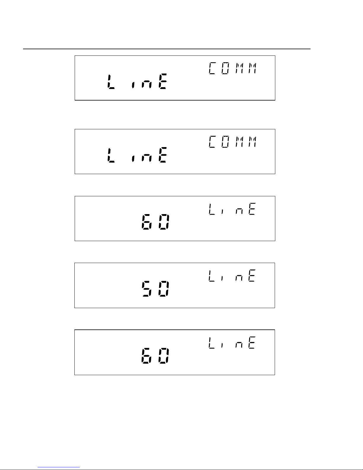
Reviewing and Setting the Line Frequency
Perform the procedure below to review or set the line frequency. Line frequency
selection allows the device to optimize internal circuitry for best accuracy. (See
Figure 2 for examples.)
• Line Frequency Choices Select 50 Hz or 60 Hz as the frequency of the
primary power when an ac source powers the device.
Table 2. Reviewing and Setting the Line Frequency
Getting Started
Configuring the 268XA
Press the COMM key to review the Line Frequency setting, or press and hold
the COMM key for 3 seconds to set the Line Frequency.
Press the up/down arrow keys until LinE (Line Frequency) appears in the
primary display (comm appears in the secondary display).
Press the ENTER key. LinE appears in the secondary display and the current
LinE frequency setting is in the primary display.
For Line Frequency set procedures, press the up/down arrow keys to select
50 (Hz) or 60 (Hz) line frequency (current setting appears bright).
Press the ENTER key to exit. (Pressing any other function key will cancel set
operations.)
5
Page 16
2680A/2686A
Getting Started Guide
REVIEW
Communications display for reviewing the line frequency
SET
Communications display for setting the line frequency
SET
Hz
Line frequency display for setting the line frequency to 60 Hz
SET
Hz
Line frequency display for setting the line frequency to 50 Hz
REVIEW
Hz
Line frequency display for reviewing the line frequency (60 Hz)
Figure 2. Examples for Reviewing and Setting the Line Frequency
6
Page 17

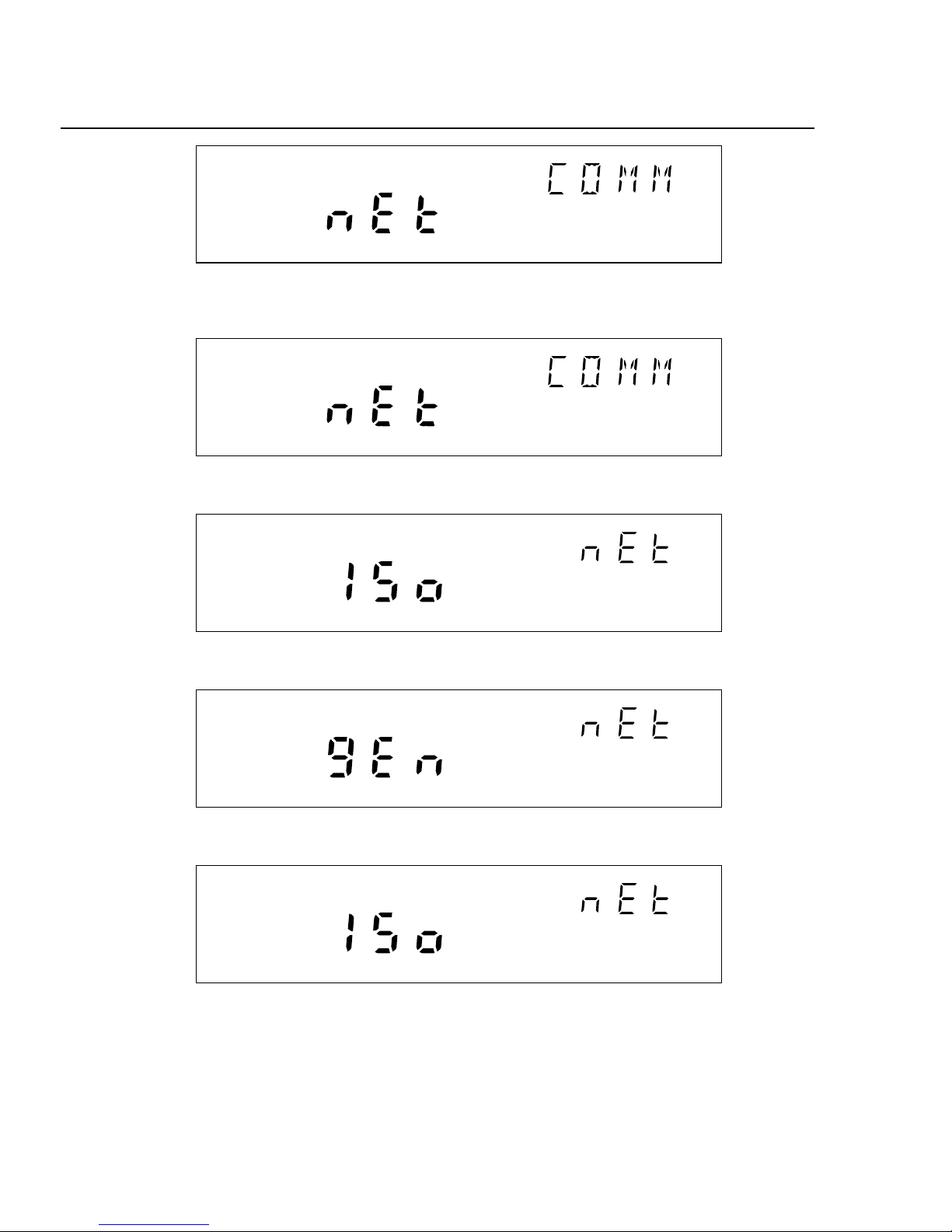
Reviewing and Setting the Network Type
Perform the procedure in below to review or set the network type to isolated.
Perform the procedure in Table 4 to review or set the network type to general. An
isolated network consists of only 268XA Series and NetDAQ 26X devices and one
or more host computers. A general network consists of devices, host computers,
and possibly servers, routers, gateways, or other network devices. (See Figure 3
for examples.)
If you use Fluke DAQ software for isolated network operation and set the devices’
network type to isolated, you do not need to know or set IP addresses for your
devices.
Table 3. Reviewing and Setting the Network Type
Getting Started
Configuring the 268XA
Press the COMM key to review the network type, or press and hold the COMM
key for 3 seconds to set the network type.
Press the up/down arrow keys until nEt (Network) appears in the primary
display (comm appears in the secondary display).
Press the ENTER key. nEt appears in the secondary display and ISo (isolated
network) or gEn (general network) is in the primary display.
To set the network type to isolated, press the up/down arrow keys to
select ISo (current setting appears bright).
Press the ENTER key to exit. (Pressing any other function key will cancel set
operations.)
7
Page 18
2680A/2686A
Getting Started Guide
REVIEW
Communications display for reviewing the network type
SET
Communications display for setting the network type
SET
Network display for setting the network type to isolated
SET
Network display for setting the network type to general
REVIEW
Network display for reviewing the network type (isolated network)
Figure 3. Examples for Reviewing and Setting the Network Type
8
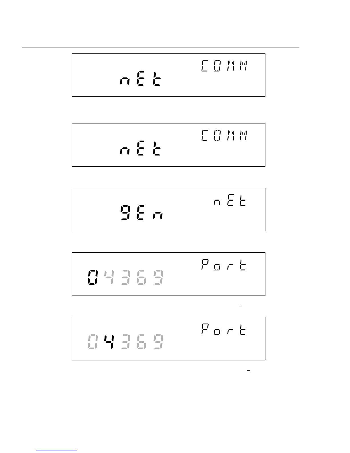
Page 19

Getting Started
Configuring the 268XA
If you set Fluke DAQ Software for general network operation, you must set the
network type of each device to general. You will need to enter an IP address, and
possibly a socket port, subnet mask and gateway address into each device. Get this
information from your network administrator.
Table 4. Reviewing and Setting the Network Type to General
Press the COMM key to review the network type, or press and hold the COMM
key for 3 seconds to set the network type.
Press the up/down arrow keys until nEt (Network) appears in the primary
display (comm appears in the secondary display).
Press the ENTER key. nEt appears in the secondary display and ISo (isolated
network) or gEn (general network) is in the primary display.
To set the network type to general, press the up/down arrow keys to
select gEn (current setting appears bright).
Press the ENTER key. (Pressing any other function key will cancel set
operations.) This displays the current Socket Port.
Press the ENTER key. This displays the first digit of the Internet Protocol
address (segment IP:0).
Press the ENTER key to exit. You must set an IP address and Socket Port
when using a general network.
9
Page 20
2680A/2686A
Getting Started Guide
REVIEW
Communications display for reviewing the netw ork type
SET
Communications display for setting the network type
SET
Network display for setting the network type to general
SET
Socket Port display for setting the first digit (for the example 04369)
SET
Socket Port display for setting the second digit (for the example 04369)
Figure 4. Examples for Reviewing and Setting General Network Parameters
10
Page 21
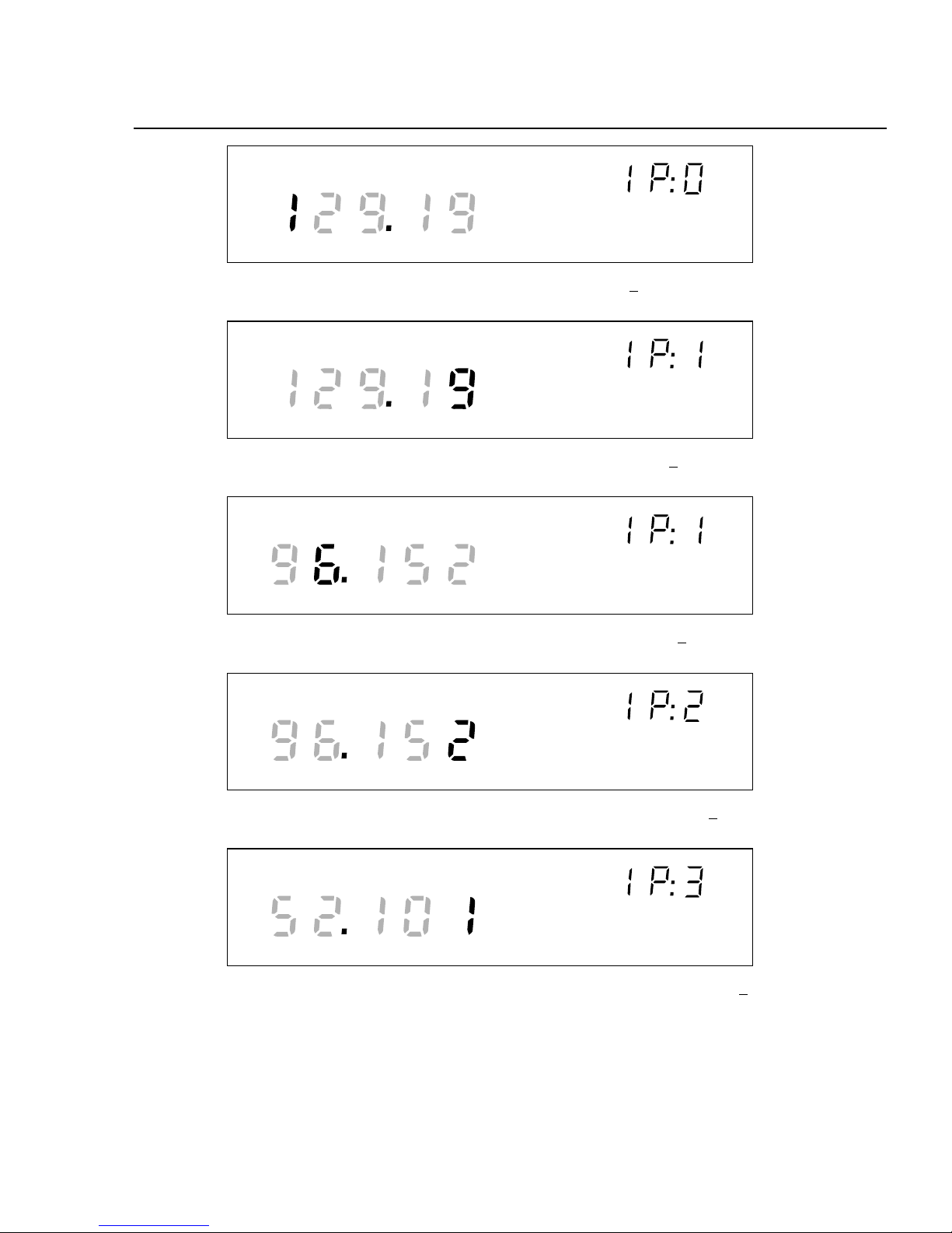
SET
IP address display for setting an IP:0 digit (for example, 129:196:152:101)
SET
IP address display for setting an IP:1 digit (for example, 129:196:152:101)
SET
Getting Started
Configuring the 268XA
IP address display for setting an IP:1 digit (for example, 129:196:152:101)
SET
IP address display for setting an IP:2 digit (for example, 129:196:152:101)
SET
IP address display for setting an IP:3 digit (for example, 129:196:152:101)
Figure 4 Examples for Reviewing and Setting General Network Parameters (cont)
11
Page 22

2680A/2686A
Getting Started Guide
Reviewing and Setting the General Network Socket Port
Perform the procedure below to review or set the general network Socket Port
(1024 to 65535). The default is 04369. In order to communicate with each other, a
host computer and an device must use the same socket port number. (See Figure 4
for examples.)
• General Network Socket Port Enter the Socket Port supplied by your
network administrator.
Table 5. Reviewing and Setting the General Network Socket Port
Press the COMM key to review the network settings, or press and hold the
COMM key for 3 seconds to set the network settings.
Press the up/down arrow keys until nEt (Network) appears in the primary
display (comm appears in the secondary display).
Press the ENTER key. nEt appears in the secondary display and ISo (isolated
network) or gEn (general network) is in the primary display.
To set the network type, press the up/down arrow keys to
select gEn.
Press the ENTER key. (Pressing any other function key will cancel set
operations.) This displays the current Socket Port.
To set the socket port, press the left/right arrow keys to select the desired
digit position (highlighted).
Press the up/down arrow keys to select the desired number, 0 to 9, for the
positioned Port digit. In this manner, select all Port digits.
Press the ENTER key. This displays the first digit of the Internet Protocol
address segment IP:0.
12
Press the ENTER key to enter the settings and exit the procedure. (Pressing
any other function key will cancel set operations.).
Page 23

Reviewing and Setting the General Network IP Address
Perform the procedure below to review or set the device’s general network Internet
Protocol (IP) address.
• General Network IP Address Enter the IP Address supplied by your
network administrator for each BCN. The format is four 3 digit segments:
IP0.IP1.IP2.IP3.
Table 6. Reviewing and Setting the General Network IP Address
Getting Started
Configuring the 268XA
Press the COMM key to review the network settings, or press and hold the
COMM key for 3 seconds to set the network settings.
Press the up/down arrow keys until nEt (Network) appears in the primary
display (comm appears in the secondary display).
Press the ENTER key. nEt appears in the secondary display and ISo (isolated
network) or gEn (general network) is in the primary display.
To set the network type, press the up/down arrow keys to
select gEn.
Press the ENTER key. (Pressing any other key will cancel set operations.) This
displays t he current Socket Port.
Press the ENTER key. This displays the first digit of the 12 digit Internet
Protocol address (grouped into four 3 digit segments: IP0 . IP1 . IP2 . IP3).
Press the left/right arrow keys to select the desired number in each segment.
The selected digit is highlighted and the segment, for example, IP2, appears.
Press the up/down arrow keys to select the desired number, 0 to 9, for the
positioned IP digit. In this manner, select all 12 IP digits.
Press the ENTER key to enter the settings and exit the procedure. (Pressing
any other function key will cancel set operations.).
13
Page 24

2680A/2686A
Getting Started Guide
Reviewing and Setting the Subnet Mask and Default Gateway
If communication between the host computer and the 2680 Series passes through a
router or gateway, you must set the subnet mask and default gateway address on
both the host computer and the device. Get this information from your network
administrator.
Perform the procedure in Table 7 to review or set the device network gateway
parameters. The network gateway parameters include turning the default gateway
feature on or off, setting a subnet mask, and setting an IP address for the gateway
attached to the local network.
Note
Set the IP address of the device before setting the gatewa y
parameters. The 268XA device checks the gateway IP address for
validity by using the device IP address.
• Default Gateway Parameters If the 268XA device and host PC are on
different subnets and must communicate through a gateway (router), turn the
default gateway feature ON and enter the subnet mask and IP address of the
gateway, as supplied by your network administrator. If you do not require a
gateway, turn the default gateway feature OFF.
• Subnet Mask The subnet mask is a 32 bit binary number expressed as four
3 digit segments, like an IP address. The subnet mask, when masked with the
device IP address, determines what the network number is. For example, if the
IP address is 129.196.180.93 and the subnet mask is 255.255.255.0, the
network number is 129.196.180.0.
The subnet mask contains a consecutive set of bits, starting at the highest order
bit, forming a binary mask value. For example, 255.255.0.0 (binary value
FFFF0000 hex) is a valid mask, but 255.255.10.0 (binary value FFFF0A00
hex) is not a valid mask, because the bits are not consecutive. 0.255.255.0
(binary value 00FFFF00 hex) is also not a valid mask, because the bits do not
begin at the highest order bit.
The subnet mask must also contain a minimum number of bits depending on
the class of the device IP address. The minimum number of bits for a class A
address is 255.0.0.0, class B is 255.255.0.0 and class C is 255.255.255.0. For
example, if the IP address is 129.196.180.93, a class B address, a subnet mask
of 255.0.0.0 is not valid, because there are too few subnet mask bits set.
• Default Gateway IP Address The default gateway IP address is the IP
address of a gateway (router) attached to the same network as the device.
When the device detects that a host PC is not on the same network (using the
network number), the data is sent through the gateway to reach the host PC.
14
Page 25

Getting Started
Configuring the 268XA
The network number of the device must match that of the gateway. For
example, if the gateway IP address is 129.196.180.93, and the subnet mask is
255.255.255.0, the network number is 129.196.180.0, and the device IP
address must be in the range 129.196.180.1 to 129.196.180.254.
Table 7. Reviewing and Setting the Subnet Mask and Default Gateway
Press the COMM key to review the parameters, or press and hold the COMM
key for 3 seconds to set the parameters.
Press the up/down arrow keys until dgAtE (default gateway) appears
in the primary display (COMM appears in the secondary display).
Press the ENTER key. dgAtE appears in the secondary display, and ON or
OFF is in the primary display.
Press the up/down arrow keys to select either ON or OFF when in set
mode.
Press the ENTER key to make the selection (pressing any other key will cancel
set operations.). If you select ON, the subnet mask appears. The subnet mask
display consists of four 3 digit segments: Sub0. Sub1. Sub2. Sub3.
Press the left/right arrow keys to select the desired number in each segment.
The selected digit is highlighted and the segment, for example Sub:0,
appears in the secondary display.
Press the up/down arrow keys to select the desired number 0 to 9, for the
positioned subnet mask digit. In this manner, select all 12 subnet mask
digits.
Press the ENTER key to make the selection (pressing any other key will cancel
set operations). If you enter an incorrect subnet mask, Error appears for 2
seconds, and the subnet mask selection stays displayed. Otherwise, the
default gateway IP address appears. The default gateway display consists of
four 3 digit segments: gAt0.gAt1.gAt2.gAt3.
Press the left/right arrow keys to select the desired number in each segment.
The selected digit becomes highlighted and the segment, e.g. gAt:0,
appears in the secondary display.
Press the up/down arrow keys to select the desired number 0 to 9, for the
positioned default gateway IP digit. In this manner, select all 12 default
gateway IP digits.
Press the ENTER key to make the selection (pressing any other key will cancel
set operations). If you enter an incorrect default gateway IP, Error displays for 2
seconds, and the default gateway IP selection stays displayed. Otherwise, the
procedure exits.
15
Page 26

2680A/2686A
Getting Started Guide
Viewing the Device Ethernet Address
Perform the procedure in below to view the Device Ethernet address. (See Figure 5
for examples.) The network administrator must know the device Ethernet address
when the device operates on a general network. You do not need this information
when you operate the device on an isolated network.
• Ethernet Address Format The Ethernet address is a 12 digit hexadecimal
number. For example, 00:80:40:12:34:56. The first 6 hexadecimal digits
represent a manufacturer, for example, 00:80:40 represents Fluke Corporation.
The remaining digits are a sequential number assigned during manufacturing.
Ethernet addresses are always unique; they are never altered, reused, or
duplicated.
• Ethernet Address Display The Ethernet address display consists of six 2
digit segments: Eadr 0 to Eadr 5. In the example above, Eadr0=00, Eadr1=80,
Eadr2=40, Eadr3=12, Eadr4=34, Eadr5=56.
Table 8. Viewing the Device Ethernet Address
Press the COMM key to open the communications display because this is a
review process only.
Press the up/down arrow keys until EAdr (Ethernet Address) appears in
the primary display (comm appears in the secondary display).
Press the ENTER key. Eadr0 appears in the secondary display, the first 5 digits
of the Ethernet address appears in the primary display (always 00.80.4).
Press the left/right arrow keys to display each byte: Eadr0 (always 00),
Eadr1 (always 80), Eadr2 (always 40), then Eadr3, Eadr4 and Eadr5.
Press the COMM key again to exit. Record the Ethernet address inside the rear
cover of this manual.
16
Page 27

REVIEW
Communications display for viewing the device Ethernet address
REVIEW
Ethernet address display for viewing byte 0 (for example 00-80-40-12-34-56)
REVIEW
Getting Started
Configuring the 268XA
Ethernet address display for viewing byte 2 (for example 00-80-40-12-34-56)
REVIEW
Ethernet address display for viewing byte 4 (for the example 00-80-40-12-34-56)
REVIEW
Ethernet address display for viewing byte 5 (for example 00-80-40-12-34-56)
Figure 5. Examples for Viewing the Ethernet Address
17
Page 28

2680A/2686A
Getting Started Guide
Host Computer and Network Preparation
This section contains information for preparing your host computer and setting up
network communication, as summarized below.
Installing Host Computer Ethernet Adapter
Skip this section if you have an Ethernet adapter installed on your computer.
Since the installation procedures for Ethernet adapters change frequently and
without notice, you must follow the instructions supplied with your particular
Ethernet adapter. If your host computer is already on a network, it probably has an
Ethernet adapter already installed.
To install an Ethernet adapter, use the following procedure:
1. Close all applications. Exit Windows and turn the host computer off.
2. Follow the installation instructions in the manual supplied with your Ethernet
adapter to install the hardware. Do not install driver software at this point.
18
Page 29

1
Install
Ethernet
Adapter
2
Interconnect
Host Computers
and
Instruments
Ethernet Card
Instrument
OR
Getting Started
Host Computer and Network Preparat ion
PC
Card
3
Install
Networking
Software
4
Install
Fluke DAQ
Software
Windows 98/NT
or higher
Fluke DAQ
for Windows
alg02f.eps
Figure 6. Preparing for Network Operation
19
Page 30

2680A/2686A
Getting Started Guide
Device and Host Computer Interconnection
You may interconnect 268X devices and host computer(s) with 10/100 BaseT
(twisted pair) wiring. If your site is already wired, you can use the wire in place. If
your site is not wired, you are connecting your device directly to your host
computer.
Host Computer/Device Direct Connection
You can connect a single device directly to a host computer using 10/100BaseT
cable, but you must use a special cable that has its transmit and receive lines
crossed. The crossed lines allow each end to transmit to the receive terminal at the
other end.
Unshielded Twisted Pair Cable
WITH RX AND TX LINES REVERSED
10/100BaseT RJ-45 Ethernet Ports
RJ-45 10/100BaseT
Outlets (Typical)
Patch Cord
Host
Computer 1
10/100BaseT Direct Connection
Figure 7. Host Computer/Device Direct Connection
RJ-45
Interface
(Typical)
Interconnection Using 10/100BaseT (Twisted Pair) Ethernet Wiring
The devices support connection via twisted pair Ethernet, usually in conjunction
with a "hub" for multiple devices Take care that you use twisted pair wires
designed for 10/100BaseT network use (phone cables will not work). Refer
interconnection issues to your network administrator.
Instrument
alg04f.eps
20
Page 31

Getting Started
Host Computer and Network Preparat ion
Direct connection between a single host computer and a single device with
10/100BaseT is possible, but you must use a special cable that has its transmit and
receive lines crossed.
The typical general network configuration uses 10BaseT Twisted Pair Ethernet for interconnection
(shown).
Connect to RJ-45
10/100BaseT Port
Instrument 1
Host
Computer 1
10/100BaseT
Twisted-Pair
Ethernet Hub
(Not Supplied)
Instrument 2
Host
Computer 2
RJ-45
Interface
(Typical)
Figure 8. Interconnection Using 10/100BaseT (Twisted Pair) Wiring
RJ-45
10/100BaseT
Outlets
(Typical)
Patch Cord
Twisted-Pair
Patch Cord
(Typical)
Instrument 3
Instrument 4
alg03f.eps
21
Page 32

2680A/2686A
Getting Started Guide
Installing Host Computer Networking Software
To establish Ethernet communication in your host computer, you must do the
following:
• Install a driver for the adapter
• Install TCP/IP protocol stack
• Set host computer networking parameters
This section discusses installing the adapter driver and the TCP/IP protocol stack.
You should install the networking software that is most appropriate for your
operating system.
Windows 98, Windows NT (Service Pack 6.0 required), ME, 2000, and XP
provide drivers for many Ethernet adapters, in addition to the TCP/IP protocol.
Complete the following procedure to load the Ethernet adapter driver and the
TCP/IP protocol stack on Windows 98. Windows NT and Windows 2000
installation is similar. The operating system may have already detected the
Ethernet adapter and added it. If so, you can skip steps 2 and 3.
1. Open the Control Panel | Network utility via Start | Settings or My Computer.
2. Click Add; select Adapter, then click Add.
3. Choose the manufacturer and network adapter. Click OK. The support for the
adapter gets installed.
4. Click Add, select Protocol then click Add. Select Microsoft TCP/IP. Click
OK. The protocol support is installed.
22
Page 33

Setting Host Computer Networking Parameters
This section discusses how to set your host computer networking parameters after
you install your adapter and networking software. If you plan to use Fluke DAQ
software for general network operation, and you are just now enabling networking,
you must set the host computer’s IP address, subnet mask, and possibly its default
gateway IP address. Obtain this information from your network administrator.
If you plan to use Fluke DAQ software for isolated network operation you must set
the host computer’s IP address to 198.178.246.1xx, and its subnet mask to
255.255.255.0. You can use any numbers for the last two digits of the host
computer IP address. Each computer on the network must have a unique number
(for example, 198.178.246.101 and 198.178.246.102).
If you plan to use Fluke DAQ software for general network operation and your
host computer is already operating on the network, skip this section.
Complete the following procedure to set the networking parameters on Windows
98. The procedure is similar on Windows NT and Windows 2000,
1. Open the Control Panel | Network utility via Start | Settings or My Computer.
Getting Started
Host Computer and Network Preparat ion
2. Highlight TCP/IP and click Properties.
3. Select the IP Address tab. Enter the IP address and subnet mask.
4. If your network administrator supplied a Default Gateway address, select the
Gateway tab. Enter the New Gateway address, click Add, and click OK.
5. Click OK to exit Network Setup.
6. Reboot your computer.
23
Page 34

2680A/2686A
Getting Started Guide
I
ntroducing Fluke DAQ Software
Fluke DAQ software provides a graphical user interface (GUI) to the 264XA and
268XA family of data acquisition products. You can use Fluke DAQ software to
easily perform the following:
Fluke DAQ supports the NetDAQ devices (2640A and 2645A) as well
as the 2680A and 2686A.
• Configure your 268XA network and device settings.
• Download/upload config urat ion to the dev ices.
• Send commands to and take readings from analog modules and the optional
DIO module.
• Monitor the devices on-line values and alarms.
• Plot trend charts, and a complete historical capability to retrieve historical
trends, alarms and export data files in CSV format.
Note
• Record and store scanned data on a PC Card (PCMCIA ATA format).
WCaution
Removing the PC card while the storage LED is on may
cause a loss of data. Before removing the card, stop the
device scanning. Loss of power while storing data may
also result in loss of data.
Note
When a PC card is used for data collection you should erase stored
data before using the card again.
Installing Fluke DAQ Software
To install Fluke DAQ software on your computer
1. Run the Launch.exe command from your distribution CD. The installation
program will prompt you for an installation location for the program and will
check if there is enough free space on you hard drive for the installation.
2. Click the Next button and wait for the installation to finish. The install time
will vary depending on the computer you are using.
3. The installation program creates a shortcut on the your desktop
when the installation is complete. Double-click the shortcut to
start Fluke DAQ.
24
Page 35

Getting Started
Installing Fluke DAQ Software
Note
You will need to reboot your computer after you install the Fluke
DAQ software.
During installation, the following directories and files are installed on you PC.
The Fluke DAQ subdirectories contain the following information
Alarm Collected alarm data and format information.
Config Miscellaneous files used in a system configuration.
Database Miscellaneous files that related to the database collection.
Hst Data collected during scanning, one file per channel.
Screen Miscellaneous files affecting the screen layout.
Symbol Bit maps used on Fluke DAQ screens.
Web Miscellaneous files associated with network communication.
Bin Files used to generate the Fluke DAQ application.
Config Saved configuration files.
Export Exported .csv scan data files.
alg100s.bmp
25
Page 36

2680A/2686A
Getting Started Guide
Understanding t he User Interface
Fluke DAQ software has a standardized and easy to use interface. This section
explains the components of the interface.
Using the Toolbar
A toolbar appears on all of the Fluke DAQ dialogs. Use the toolbar buttons to add
and configure devices 268XA devices and to navigate through the Fluke DAQ
application. Each button on the toolbar has a tool tip that iden ti fi es the button
function. Using the mouse, point to a button to view the tool tip.
Table 9. Fluke DAQ Toolbar Buttons
Button Function
Logon button.
alg101s.bmp
Used to log on to the Fluke DAQ application. The Fluke DAQ
administrator (Root user) is able to create user accounts and set up
rights to configure devices. Guest users do not have rights to perform
configuration tasks.
Security System Configuration button.
The system security conf iguration feature allows the ad ministrator to
add and remove Fluke DAQ users, allow users to configure devices,
and to change user passwords. Only the administrator (Root user) can
use the security system configuration function.
Configuration button.
Used to configure networks, devices, modules, and channels.
Communication button.
Used to access the Communication dialogs, display the
communication status of connected network components, and allow
you to interact with those components.
The communication icon can also assume three states in the
TreeView panel.
• Dark computer screens on the icon indicates that communication
is disabled.
• Color on the computer screens on the icon indicates that
• A blinking red X through a computer screen indicates a
26
communication is enabled.
communication failure.
Page 37

Table 3-1. Fluke DAQ Toolbar Buttons (cont)
Button Function
Trend button.
Used to access the Trend dialog to view the scanned data collected
from 268XA devices.
Alarm button.
You can use the Alarm View dialog to view On Line and History
alarms.
The Alarm status icon can also assume two states in the TreeView
panel. When an alarm is activated the Alarm icon turns red. The icon
turns black after you give an Ack command (Last Alarm or All Alarms)
in the Alarms dialog.
Web and Alarm Mail Settings button.
Used to enter Fluke DAQ web configuration information and to
configure Fluke DAQ to send e-mail messages reporting alarm
condition.
Getting Started
Understanding the User Interface
Exit button.
Exit the Fluke DAQ application.
27
Page 38

2680A/2686A
Getting Started Guide
Understanding the Workspace Area
The Workspace Area consists of a network TreeView and a set of buttons. Use the
Workspace Area to:
• Open, Save, and Remove configuration files. You can also use the Save As
button to rename an existing configuration file.
• Insert and Remove devices, modules and channels
• Navigate through the configuration setup dialogs
Open an existing
configuration file
Save a
configuration file
Insert a
Treeview item
268XA device
Create a new
configuration file
Specify configuration
file name and path
Remove a Treeview item
Configuration item
file name (Root Node)
PAI Module
Channels
FAI Module
Channels
DIO Module
Computed channels
28
alg67f.eps
Page 39

Checking Operational Status
The icons in the TreeView change to indicate the device status. Below are all the
possible icons and their meaning:
Device Status Icon
• Yellow or blue device icons indicates the device is not connected.
• Green device icon indicates the device is connected and communicating.
• Red device icon indicates an device error. You can view error information in
the Communication dialog
Module Status Icon
• Dimmed module icon indicates the module is not being scanned.
• Green module icon indicates the module is being scanned.
• Red module icon indicates the module is being scanned and a channel is in
alarm condition.
Getting Started
Understanding the User Interface
Computed Channel Status Icon
• Blue channel icon indicates channels are not being scanned.
• Green channel icon indicates channels are being scanned.
• Red channel icon indicates channel in an alarm condition.
I/O Module 6
• Black digital I/O icon indicates all the channels are turned off.
• Green digital I/O icon indicates a channel is turned on by a external activation
or by a user command.
• Red digital I/O icon indicates a channel is activated by an alarm condition.
29
Page 40

2680A/2686A
Getting Started Guide
Configuration Dialogs
The Configuration dialog that appears depends on the node (device, module, or
channel) you select in the TreeView panel.
You can also use copy and paste functionality to save configuration time. Channel
settings can be copied from one channel to another in the same device, or you can
copy a whole module or a group of channel settings from one device to another.
To copy a channel, highlight the channel you want to copy, then click the right
mouse button and select Copy. Next, highlight the module where you want to add
the channel, then click the right mouse button and select Paste. A new channel
with the same configuration will be added to the module.
You can also use the same method to change channel settings. Highlight a channel,
then click the right mouse button and select Copy. Next, highlight the channel you
want to change, click the right mouse button and select Paste to paste the
configuration inform ation.
As you move from a Configuration dialog to a Communication
dialog, the device that was previously selected in the dialog is still
selected. For example, if device 01 is selected in the Configuration
dialog and you move to a Communication dialog, the device will only
be highlighted if it was selected the last time you were in the
Communication dialog. Dialog selections are remembered and are
independent.
Note
Fluke DAQ uses the following Configuration dialogs:
Network Configuration Dialog
You can use the Network Configuration dialog to group the devices as in a
master/slave arrangement and to select the network type (General or Isolated). The
Network Configuration dialog appears when you click on the root node in the
TreeView.
Device Configuration Dialog
You can configure your 268XA devices using the Fluke DAQ Configuration
dialog. This dialog appears when you select a 268XA device in the TreeView. You
can use the Configuration dialogs to:
• Set up the device network settings (IP address and Port number)
• Verify the IP Address and the connection
• Upload and download the configuration from/to the device
• Save and load the configuration to and from the PC card (2686A only)
30
Page 41

The Save command saves the actual 2686A configuration to the PC
Card. The Load command loads the configuration from the PC Card
to the 2686A.
• Set up the device general settings
• Specify which module will control the trigger out signal for master/slave
operation
Module Configuration Dialog
A 268XA device can have up to 6 modules with specific configuration settings.
The Module Configuration dialog appears when you select a module in the
TreeView.
Analog Channel Configuration Dialog
Use the Analog Channel Configuration dialog to set function, range, and alarm
information.
Getting Started
Understanding the User Interface
Note
DIO Configuration Dialog
Use the DIO Configuration dialog to enter totalizer configuration information. To
set relays and I/O pins, see the DIO Communication dialog described later in this
Chapter.
Computed Channel Configuration Dialog
268XA devices can have up to 60 computed channels, with all computed channels
available for configuration in one view.
Computed channels provide a way to directly use measurement results in a
calculation. The calculation results can be used to set alarms or as part of other
calculations. A computed channel is inserted in a similar manner as a channel for a
FAI or PAI. Highlight the Computed Channel icon and click on the Insert button.
Detailed instructions for using the Configuration dialogs is provided later in this
Chapter.
Note
Computed channel values are only updated when scanning is active.
31
Page 42

2680A/2686A
Getting Started Guide
Communication Dialogs
The Communication dialogs display the communication status of connected
network components and allow you to interact with those components. Fluke DAQ
uses the following Communication dialogs. Using the Communication dialogs you
can monitor and interact with:
Device Communication and Status Dialog
You can use the Device Communication and Status dialog to perform the
following tasks:
• View device status and reset device errors
• Start/Stop scan and communication with all the modules
• Reset the totalizer and the PC Card status
• Upload scan data from the PC Card, format the PC Card, and remove scan data
from the PC Card
Module Communication Dialog
You can use the Module Communication dialog to:
• View the current channel values
• View the alarm conditions
• Start/Stop the module scan
Digital I/O Points Dialog
You can use the Digital I/O Points Communication dialog to set any of the 8 relays
or 20 DIO pins active when an alarm condition occurs in the channel.
Computed Channels Dialog
You can use the Computed Channels communication dialog to perform the
following tasks:
• View current values of computed channels
• View alarm conditions of computed channels
Security Dialogs
You can use the system security features to protect device configuration
information. The system security feature allows the administrator to add and
remove Fluke DAQ users, allow other users to configure devices, and to change
user passwords
32
Page 43

Trend Dialog
You can use the Trend dialog to view the scanned data collected from the 268XA
devices. The charts can be On Line or Historical. You can use the Export button to
export data to a CSV file that you can manipulate using Excel.
Alarm Dialog
You can use the Alarm View dialog to view On Line and History alarms. You can
filter the alarms by device ID, module and channel. When an alarm occurs, the
device Icon in the configuration window changes to a red color. As long as the
alarm exists, the Icon remains red. In the Alarm window, a red line of information
shows the status of the alarm.
Mail and Web Settings Dialogs
You can use the Web and Alarm Mail Settings dialog to enter Fluke DAQ web
configuration information and to configure Fluke DAQ to send e-mail messages
reporting alarm condition.
The Web Settings portion of dialog is used to specify a URL where scanned values
from your 268XA device will be sent.
Getting Started
Understanding the User Interface
33
Page 44

2680A/2686A
Getting Started Guide
Managing Your Network Using Fluke DAQ
The following procedures provide detailed instructions for using Fluke DAQ to:
• Insert and configure 268XA devices, modules, channels, and computed
channels.
• Start a scan
• View scan data.
• View alarms.
Inserting and Configuring a 268XA Device
To insert and configure a device
1. Double-click the icon on your desktop to start Fluke DAQ.
2. Specify basic settings in the Fluke DAQ Application dialog.
34
alg102s.bmp
Page 45

The dialog box entries include:
Configuration file
Getting Started
Managing Your Network Using Fluke DAQ
Click the
button or the button the to load an existing
configuration file.
Network Type
Isolated if the PC is connected directly to the 268XA device or General if the
268XA is part of a network.
Port Number
4369 is the default port number. Fluke recommends that you use the default
port number.
Group is externally wired
All devices may be wired together in a master/slave arrangement.
Advanced Setting autodisable scan – Interval 3 (autoscan rate)
Interval 3 is the rate at which alarm conditions will be monitored. If disabled,
alarm conditions will be monitored only when the associated channel is
scanned during a regular scan interval.
Max 999999 seconds
Min 0.001 seconds
3. To insert a device, select the .cfg file in the TreeView panel and click the
Insert button.
alg103s.bmp
35
Page 46

2680A/2686A
Getting Started Guide
4. Specify the Base Channel (1 to 99) and Device Type and click OK. A device is
attached to the new configuration. As part of the insertion process, you can
specify a base channel number. This number is used to differentiate channels
in different devices. You can insert up to 99 Base Channels of the same
Device Type. The Base Channel number auto-increments when you add
devices.
Fluke DAQ also supports 2640A and 2645A NetDAQ devices. Some
of the Fluke DAQ configuration dialogs may differ from those for the
268XA.
alg104s.bmp
Note
5. In the TreeView panel, select the device you just added.
alg105s.bmp
36
Page 47

Getting Started
Managing Your Network Using Fluke DAQ
6. Set the IP Address on the Device Settings dialog. Other fields are optional.
You may need to contact your Internet support staff to determine the IP
Address.
alg106s.bmp
The dialog box entries include:
IP Address
Enter the IP Address of the device you are adding.
Verify Button
Click the Verify button to ping the device and verify that the IP Address is
correct. The device and your PC must both be connected to the network for
this to work.
Configuration transfer
You can transfer configuration information from the PC to the device, from
the device to the PC, or from a PC Card to a PC or the device. PC Card
operations are available only for the 2686A.
Description
Enter a meaningful description of the device. 35 characters maximum.
Temperature Units
Specify Celsius or Fahrenheit. This will automatically select temperature units
for all temperature measurements.
37
Page 48

2680A/2686A
Getting Started Guide
Monitor Channel
Select a channel measurement to display on the device front panel. You can
also choose to increment though active channels or to automatically scan
through all active channels. Default is None.
Scan Parameters
Parameters you can set to start, stop, and save scan data.
You can also select Start Scan on Power Up for stand-alone
operation or to automatically start scanning after a power loss.
Scan Overflow
You can choose to overwrite old data or stop receiving data when the buffer is
full.
Log to PC Card (2686A only)
Never
Ignore the PC card (default setting).
Note
Always
Always write to the PC card. This selection is useful for stand-alone
applications or when you want data backup.
Note
When the card is full, an error message will be generated and
scanning will stop.
Trigger Out
Used to specify a Trigger Out module. Trigger out is the physical Trigger
output of a 268XA device. It is the Trigger Out signal out on the rear panel
connector of the mainframe. If you want to set up a master/slave relationship,
set a module in a 268XA device to control the Trigger Out signal and wire that
signal to the Trigger In of all the salve devices. You will then need to
configure a module in a slave device to take a reading when an External
Trigger was received. The External Signal is the same as the physical Trigger
In located on the back of the mainframe.
38
Page 49

Inserting and Configuring a Module
To insert and configure a module
1. Highlight a device in the TreeView panel and click the Insert button.
2. Specify the number and type of modules you want to insert in the Module
dialog box.
Getting Started
Managing Your Network Using Fluke DAQ
alg107s.bmp
alg108s.bmp
The dialog box entries include:
Module Number
You can attach up to 6 modules to the device. You can only have a Digital I/O
in Module Slot 6 and can have only one per device.
Module Type
Valid module types are Analog PAI, Analog FAI, or Digital DIO.
39
Page 50

2680A/2686A
Getting Started Guide
3. Click OK. The modules are added to the device and appear in the TreeView
panel.
4. Select one of the analog modules you inserted and the Analog Module settings
dialog appears.
alg109s.bmp
40
alg110s.bmp
Page 51

Getting Started
Managing Your Network Using Fluke DAQ
The dialog box entries include:
Interval Trigger
Uses the interval timer (interval 1 timer) to set the scan rate for normal
operation in a module. The interval is user settable.
External Trigger
Uses the Trigger input signal to start a scan. Every time the external trigger is
activated, another scan is taken.
Alarm Trigger
Uses a second interval timer (interval 2 timer) to start scanning when an alarm
condition is encountered by the module. There is an interval timer (interval 3
timer) used to look for alarms. The default for that timer is 0.1 s for the FAI
and 1 s for the PAI.
Drift Correction
Automatically selected when you set the reading rate to Slow (High Res.). You
can also click to clear the check box. Drift correction is used primarily to
compensate for temperature drift. Clearing the check box allows readings to be
taken more quickly.
Reading Rate
Select the slow reading rate for high precision or the fast reading rate for high
speed. Actual reading rate depends on the function you select.
Conditional Scan Storage
Allows you to specify when to store scan data. Always is the default selection.
On Alarm stores scan data as long as the alarm condition exists. On Alarm
Transition stores scan data only when the alarm first occurs. On Alarm stores
the least amount of data.
On Line CSV file creation
Moves scan data directly to a .csv compatible file instead of storing it first in a
binary format.
41
Page 52

2680A/2686A
Getting Started Guide
If you are configuring a DIO module, the Totalizer Configuration
dialog appears.
Note
42
The dialog box entries include:
Start Count
Used to specify a start count.
Debounce
Select debounce to ignore signals with a period less than 2 ms (500 Hz);
otherwise, signals up to 5 kHz can be counted.
Direction
If you entered a start count, the start count is reloaded when the totalizer
reaches the terminal count. The totalizer can count up or down to zero.
You can also highlight the IO module and click the
button for more DIO
settings including digital IO points and relays.
alg111s.bmp
Page 53

Inserting and Configuring a Channel
After selecting a module, you need to add channels to the module.
To insert and configure a Channel
1. Highlight a module in the TreeView panel and click the Insert button.
2. Specify the number of channels you want to insert on the Insert Channel
dialog box.
Getting Started
Managing Your Network Using Fluke DAQ
alg112s.bmp
alg113s.bmp
3. Click OK. The channels are added to the module and appear in the TreeView
panel.
alg114s.bmp
43
Page 54

2680A/2686A
Getting Started Guide
4. Select a channel and the Module settings dialog appears.
alg115s.bmp
The dialog box entries include:
CH #
XX-YYY. The first two digits identify the chassis (01-99). The next digit
identifies the module (1-6), and the last two digits identify the channel (1-20).
Label
Use the label field to identify where the channel is used in your application.
Unit Label
Used to identify the unit of measurement (°C or °F).
Function
Identifies the type of measurement being performed.
Range
Amplitude range for the measurement. Use auto when you are unsure of the
range.
Alarm Type
Use Normal alarm if the measurement goes above or below the Alarm 1 or
Alarm 2 level. Use Band to alarm if the signal falls between two levels.
44
Page 55

Getting Started
Managing Your Network Using Fluke DAQ
Alarm 1 or Alarm 2
Each channel has two alarms. You can set the alarms to Off, Low, or High. An
alarm condition occurs when a measurement falls below a low alarm value
(Low) or rises above a high alarm value (High). Fluke DAQ records all alarm
conditions in a data file.
Open Thermocouple Detection
Provides for notification if an open therm ocouple is detec t ed.
Factors (Mx+B)
Used to scale measurements. Mx + B scaling multiplies a measurement by a
multiplier (M) and then applies an offset (B). For example, Mx+B scaling of
100x+50 applied to a measured value of 1.15 would result in a reading of
100(1.15)+50=165.
Input or Scaled Range
Use the M and B values to calculate the Input and Scaled range or you can
enter the Input and Scaled range and Fluke DAQ will calculate the M and B
values for you.
Configuring a Computed Channel
Computed channels provide a means to calculate values based on measurements.
For example, if Channel 1 measures dc V and Channel 2 measures dc I, you could
use a computed channel to calculate instantaneous power (Channel 1 x Channel 2).
For a computed channel to execute, it must be associated with the scanning of a
module. You need to choose a module in the Scan with Module area for this
association. The default is module 1.
To configure a computed channel
1. Highlight the Computed Channels icon in the TreeView panel and click the
Insert button.
alg116s.bmp
45
Page 56

2680A/2686A
Getting Started Guide
2. Specify the number of channels you want to insert on the Insert Channel
dialog box.
3. Click OK. The computed channels are added and appear in the TreeView
panel.
alg117s.bmp
46
alg118s.bmp
Page 57

Getting Started
Managing Your Network Using Fluke DAQ
4. Select a computed channel and the Computed Channel settings dialog appears.
alg119s.bmp
The dialog box entries include:
CH #
Computed channels are assigned channel numbers from 901 to 960.
Label
Use the label field to identify where the computed channel is used.
Unit Label
The value to apply to the label. For example, you may want the calculated
value shown as Watts.
Function
You can take the average reading from one channel, subtract the measurement
of one channel from the measurement of another channel, or generate an
equation based on measurements.
Alarm Type
Use Normal alarm if the measurement goes above or below the Alarm 1 or
Alarm 2 level. Use Band to alarm if the signal falls between two levels.
47
Page 58

2680A/2686A
Getting Started Guide
Alarm 1 or Alarm 2
Each channel has two alarms. You can set the alarms to Off, Low, or High. An
alarm condition occurs when a measurement falls below a low alarm value
(Low) or rises above a high alarm value (High). Fluke DAQ records all alarm
conditions in a data file.
Digital Output
Used to output a digital signal or close a relay if an alarm is detected.
Use Channel as Alarm Trigger
Select if channel reading will be used to trig g er an alarm .
Trigger Scan With Module
Calculate the computed channel any time a module is scanned.
Channel A or Channel B
Select from the configured channels in the device.
Note
You cannot select channels in another device.
Equation
See Appendix E for detailed information on computed channel equations.
Average Channels
Select which channels you want to average.
Factors (Mx + B)
Used to enter a linear equation in two ways. You can either enter the slope (M)
and offset (B) or enter input range. Scale range, slope, and offset are entered
automatically when you press the Calculate button. “X” will be replaced with
the computed channel number.
Input or Scaled Range
Use the M and B values to calculate the Input and Scaled range or you can
enter the Input and Scaled range and Fluke DAQ will calculate the M and B
values for you.
48
Page 59

Using Equations with Computed Channels
Each computed channel can have an expression of 250 characters but the
maximum number of characters available in all 60 channels is limited to 6,000
characters.
For example, you could use an equation to calculate the rate of flow in gallons per
second. The rate of flow could be calculated as follows. Since TS is in
milliseconds, you need to divide by 1000 to calculate gallons per second. In this
example, during the first pass, C902 will not be defined and the result will be not a
number (#Inf). However, in subsequent passes, C902 will be defined and will
provide the correct result.
C101 = some fake measurement to force the time calculation
C901 = (TOT-C902)/(TS/1000)
C902 = TOT
Note
You need one physical channel configured in the module that you’re
scanning for this to work even though you’re not using the channel in
the expression.
Getting Started
Managing Your Network Using Fluke DAQ
Computed channels and the time value are initialized to zero at the beginning of
scanning. Physical channels that haven’t been measured are still initialized to
positive infinity.
To measure the total energy used by a simple system, a calculation could be
generated using the equation, energy = R x I^2 * time, as follows:
c101 = Ohms
c102 = Current
c959 = c959+c960
c960 = c101*c102**2*ts/1000
Note
This equation assumes that the resistance and current are constant
for the duration of the time interval. It also does not calculate the
energy used in the first increment of time.
49
Page 60

2680A/2686A
Getting Started Guide
The following is a list of the valid notations.
Axxx Alarm on/off (Boolean value of 1 or 0)
Cxxx Any channel measurement
C9xx Computed channel
TS Time since last measurement (milli seconds)
TOT Totalizer
Operators +, -, *, /, **, unary +, unary -, abs, exp, int, ln, log, and sqr.
alg120s.bmp
50
Page 61

Starting a Scan
You can scan for data using a configuration scan, a device scan, or by using Spy.
All scanning options are available in the Communication window.
You must have channels configured for operation before starting a
scan.
Starting a Configuration Scan
To start a configuration scan
Getting Started
Managing Your Network Using Fluke DAQ
Note
1. Click the
the TreeView panel.
2. Click
on the Fluke DAQ toolbar and highlight the configuration in
to start the scan. Click to stop the scan.
alg121s.bmp
51
Page 62

2680A/2686A
Getting Started Guide
Starting a Device Scan
To start a device scan
1. Click the
TreeView panel.
2. Click
on the Fluke DAQ toolbar and highlight a device in the
to start the scan. Click to stop the scan.
52
alg122s.bmp
Page 63

Starting a Scan Using Spy
Spy triggers and collects its own measurements from up to eight channels from
any combination of devices. The data is not stored and the devices you are
checking do not need to be scanning.
To start a Spy scan
Getting Started
Managing Your Network Using Fluke DAQ
1. Click the
on the Fluke DAQ toolbar. The Spy icon appears in the lowest
item in the TreeView panel.
2. Click the Spy icon and the Spy window appears. You may select up to 8
channels, including DIO and totalizer.
3. Click to start the scan. Click to stop the scan.
alg123s.bmp
53
Page 64

2680A/2686A
Getting Started Guide
Viewing Module Measurement Data
You can view measurement data from a module as it is recorded. Selecting a
module shows all 20 channels as for the Computer Channels. Modules that have
no channels configured display question marks. NC indicates that a channel is not
configured.
To view module measurement data
1. Click the
on the Fluke DAQ toolbar.
2. Highlight a module in the TreeView panel and the module measurement data
appears.
54
alg124s.bmp
Page 65

Managing Your Network Using Fluke DAQ
Using the Digital I/O Points Communication Dialog
You can use the Digital I/O Points Communication dialog to set any of the 8 relays
or 20 DIO pins active when an alarm condition occurs in the channel. You can also
view status of all of the relays and DIO pins and set or clear IO bits and relays.
Bits or relays you set display a green dot. Bits or relays set by an alarm have a red
dot. A bit set by an external signal has a blue dot. There is no way to set a relay
externally. When a relay is set, it has closed contacts. When a bit is set, it has a
logic low signal (also called activ e low ).
To view digital I/O points dialog
Getting Started
1. Click the
on the Fluke DAQ toolbar.
2. Highlight an I/O module in the TreeView panel and the Digital I/O Points
dialog appears.
alg125s.bmp
55
Page 66

2680A/2686A
Getting Started Guide
Using Trend to View Collected Data
You can use the Trend dialog to view the scanned data collected from the 268XA
devices. The charts can be On Line or Historical. You can use the Export button to
export data to a CSV file that you can manipulate using Excel.
You can select up to eight channels to view on the strip chart. If a particular
channel is not active, question marks are displayed. A horizontal cursor is used to
find the time a signal reached a certain amplitude. A user can use the key
combination <CTRL><ALT><Print Screen> to copy a bit map of the chart and
paste it to a word processing document.
channels in that device that are also shown in the Trend window are
replaced with ???????. Channels that are still scanning will continue to
show the latest data.
To use the trend feature
If a device is stopped, the data for all
1. Click the
appears.
button on the Fluke DAQ toolbar and the Trend dialog
56
alg126.bmp
Page 67

Getting Started
Managing Your Network Using Fluke DAQ
The dialog box entries include:
Pen
Click to select the device, module, or channel that you want to view in
the chart. You can view up to 8 items on the chart.
Type
Specify On Line or History scan view. History view shows the last set of data
displayed with the pens.
Zoom
Use
to expand or compress the time interval you are viewing.
Use
to increase or lower the amplitude resolution
Export
Press the Export button to generate the Export CSV file dialog shown below.
Click the OK button to start the conversion. The "Conversion complete"
message appear when the operation is complete. Scanning can continue during
the conversion process but the rate at which the new scan data can be uploaded
from a device will be slowed.
Export generates several files per module for an export. The export function
takes files from the Hst directory and generates new "csv" files in the Export
directory. You can select the base name of the files generated. A file is
generated for each module. Two files are generated for the computed channels
(1-30 and 31-60). A separate file is created for the DIO/totalizer/relay module.
57
Page 68

2680A/2686A
Getting Started Guide
alg127.bmp
Device ID
Any device from 1 to 99.
Module
A specific module in a device or you can select all of the modules.
Start Date/Start Time
Start Date and Start Time are used to select the data. Data is stored with the
date the scan began.
Duration
Duration is the amount of time to be converted. Note that the maximum time
allowed for the conversion to a .csv file is 24 hours
CSF file
The directory where the converted file will be stored.
58
Page 69

Changing the Chart Display
To change the strip chart display
• The Trend Setting dialog appears when you double-click on the chart screen.
Use the Trend Settings dialog to change the location of the upper and lower
boundary points, the scaling seen on the chart, and the color of the plot pens
you are using.
Getting Started
Managing Your Network Using Fluke DAQ
alg128s.bmp
59
Page 70

2680A/2686A
Getting Started Guide
Viewing Alarms
You can use the Alarm View dialog to view On Line and History alarms. You can
filter the alarms by device ID, module and channel. When an alarm occurs, the
color of the device icon in the configuration window changes to red. As long as the
alarm exists, the icon remains red. In the Alarm window, a red line of information
shows the status of the alarm.
If the alarm condition goes away before you acknowledge the alarm, the alarm
icon changes to blue. When you acknowledge an alarm, it turns green. All alarm
conditions are recorded in the Alarm History dialog. If an alarm appears in red in
the Alarm History dialog, it will not be duplicated. If an alarm is active, it must be
acknowledged before it will be displayed again. When a channel has two alarms,
only one alarm can be active at a time. If one alarm becomes active and then a
second alarm becomes active, Fluke DAQ will acknowledge the first alarm and
show the second alarm as active.
To view alarms
• Click the
button on the Fluke DAQ toolbar and the Alarm View dialog
appears.
When you select the On Line option, a red line of text with information about
the alarm is printed to the screen when a new alarm is detected.
60
alg129.bmp
Page 71

Getting Started
Managing Your Network Using Fluke DAQ
The dialog box entries for On Line include:
Type
Specify On Line or History alarm view.
Ack
Click the appropriate button to acknowledge the Last Alarm or All Alarms.
Alarm Device Filters
Choose to view alarms from a select set of devices, modules, and channel.
When you choose the History option, you can view alarms over a period of
time. Each time an alarm changes state the new color is added to the history
screen. You can view alarms that have occurred over a period of time or for a
specific devices, modules, or channels.
The dialog box entries for History include:
Type
Specify On Line or History alarm view.
Period of Viewing
Specify the year, day(s), and month that want to view.
Ack
Click the appropriate button to acknowledge the Last Alarm or All Alarms.
alg130.bmp
61
Page 72

2680A/2686A
Getting Started Guide
Alarm Device Filters
Choose to view alarms from a select set of devices, modules, and channel.
Using Fluke DAQ System Security Features
You can use the system security features to protect device configuration
information. The system security feature allows the administrator to add and
remove Fluke DAQ users, allow other users to configure devices, and to change
user passwords. Only the administrator (Root user) can use the security system
configuration function.
The Root password is blank when Fluke DAQ is installed on your
PC. Use the system security features to create and remove an
administrator password and grant additional access to Fluke DAQ.
To use the system security feature
Note
• Click the
Dialog appears.
button on the Fluke DAQ toolbar and the System Security
alg131s.bmp
62
Page 73

Configuring Web and Alarm Mail Settings
You can use the Web and Alarm Mail Settings dialog to enter Fluke DAQ web
configuration information and to configure Fluke DAQ to send e-mail messages
reporting alarm condition.
The Web Settings portion of dialog is used to specify a URL where scanned values
from your 268XA device will be sent. Use the Alarm Mail Settings portion of the
dialog to configure Fluke DAQ to automatically send e-mail messages reporting
alarm condition using the Simple Mail Transfer Protocol (SMTP).
Note
To use the e-mail and web features, your PC must be connected to a
network supporting the Transmission Control Protocol/Internet
Protocol (TCP/IP).
To enter web and alarm mail settings
Getting Started
Managing Your Network Using Fluke DAQ
• Click the
Dialog appears.
button on the Fluke DAQ toolbar and the System Security
alg132s.bmp
63
Page 74

2680A/2686A
Getting Started Guide
The dialog box entries include:
Data Server IP Address
The IP address of the computer running the Fluke DAQ application.
Fluke DAQ fills in this field with the first IP address found on the computer.
You must change this setting if you want to use a different interface
or if you are using a Dynamic Host Configuration Protocol (DHCP)
on your server. If you are using a DHCP server, use the computer
name instead of an IP address.
Uniform Resource Locator (URL)
The address where Fluke DAQ web files will be stored on the Internet.
SMTP Server IP Address
SMTP name or IP address. SMTP is the Simple Mail Transfer Protocol, a
protocol for sending e-mail messages between servers.
Originator E-Mail Address
Sender e-mail address.
Note
POP 3 Server IP Address
POP 3 name or IP Address. POP is the Post Office Protocol, used to retrieve
e-mail from a mail server.
User Name
User name for authentication.
Subject
Subject shown in the e-mail message.
To
Type the names of the people your want to send the message to.
CC
Type the names of the people your want to send a copy of the message to.
BCC
Types the names of people who should receive the message while their names
are hidden from other recipients of the message.
Send alarms by e-mail
Select the check box to enable the alarm mail settings feature.
Update
Click the Update button after changing any of the alarm mail settings.
64
 Loading...