

Page 1

CV200, CV300, CV400
CV201, CV301, CV401
ClirVu IR Windows
Installation Guide
PN 4341125
May 2013
© 2013 Fluke Corporation. All rights reserved. All product names are trademarks of their respective companies.
Product specications are subject to change without notice.
English
Page 2
1 2
CV200, CV300, CV400
ClirVu IR Window
Introduction
The ClirVu IR Window is a precision made accessory which, when accurately
surface of a Type 1, 2, 3/12, 3, and 12 enclosures, or as appropriate. All models
are for indoor and outdoor use.
Read and understand these instructions thoroughly before attempting to install
the units.
All of the items in Table 1 are available from Fluke.
Series Size Nema Type
CV200 50 mm (2″) 4, 12
CV300 75 mm (3″) 4, 12
CV400 100 mm (4″) 4, 12
PN 4341125
May 2013
© 2013 Fluke Corporation. All rights reserved. All product names are trademarks of their respective companies.
Installation Guide
Table 1. ClirVu IR Window Models
43 6
7
5
1
4
3
2
8
Page 3

Introduction
The ClirVu IR Window allows the exibility to inspect an electrical enclosure both
visually and with infrared. Use this accessory on the at surface of a Type 1, 2,
3/12, 3, and 4/12 enclosures, or as appropriate. All models are for indoor and
outdoor use. Table 1 is a list of the models available from Fluke.
Table 1. ClirVu IR Window Models
Model IR Window Size
CV200, CV201 50 mm (2 in)
CV300, CV301 75 mm (3 in)
CV400, CV401 100 mm (4 in)
How to Contact Fluke
To contact Fluke, call one of the following telephone numbers:
● Technical Support USA: 1-800-44-FLUKE (1-800-443-5853)
● Calibration/Repair USA: 1-888-99-FLUKE (1-888-993-5853)
● Canada: 1-800-36-FLUKE (1-800-363-5853)
● Europe: +31 402-675-200
● Japan: +81-3-3434-0181
● Singapore: +65-6799-5566
● Anywhere in the world: +1-425-446-5500
Or, visit Fluke’s website at http://www.uke.com/irwindows.
To view, print, or download the latest manual supplement, visit
http://us.uke.com/usen/support/manuals.
Page 4

Safety Information
A Warning identies conditions and procedures that are dangerous to the user.
Symbols used on the Product and in this document are in Table 2.
Warning
To prevent damage or injury:
● Read all directions before the installation.
● Comply with local and national safety requirements when working in
hazardous locations.
● Wear appropriate eye and ear protection.
● Check the window for cracks and damage before installation.
● Keep the cover closed and latched except during installation, viewing, or
temperature measurement.
Table 2. Symbols
Symbol Explanation
�
TYPE 4/12 NEMA Standard. Suitable for indoor/outdoor use.
Risk of danger. Important information. See manual.
Underwriters’ Laboratories, Inc. UL recognized component in North America.
Conforms to requirements of European Union directives.
This product complies with the WEEE Directive (2002/96/EC) marking requirements.
The afxed label indicates that you must not discard this electrical/electronic product in
domestic household waste. Product Category: With reference to the equipment types
in the WEEE Directive Annex I, this product is classed as category 9 “Monitoring and
Control Instrumentation” product. Do not dispose of this product as unsorted municipal
waste. Go to Fluke’s website for recycling information.
2
Page 5

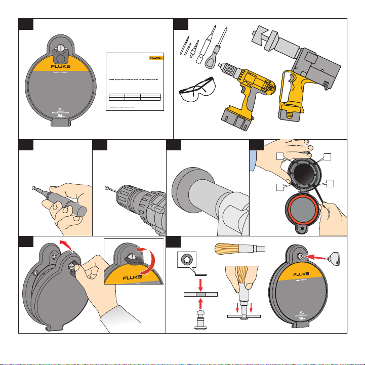
Before You Start
When your IR Window arrives, unpack the unit. Identify and make sure all the
parts are in the shipment. See Figure 1.
Required tools for installation, see Figure 2:
• Electro-hydraulic hole punch
• Greenlee Punch/Die
• Drilling machine
• Center punch
• Calibrated torque driver
Site Preparation
To prepare the installation site:
1. Mark a pilot hole with the center punch. See Figure 3.
2. Drill a 6 mm (0.2 in) pilot hole with the twist drill.
3. Use a Kwik Stepper drill bit to enlarge the 6 mm (0.2 in) pilot hole to 20 mm
(0.8 in). Or, drill a 10 mm (0.4 in) pilot hole and then enlarge the hole to
22.5 mm (0.875 in) with a Greenlee Punch/Die 71BB. See Figure 4.
4. Select the correct punch/die. See Table 3.
5. Use the Greenlee Punch/Die with the Electro-hydraulic hole punch to make
the hole diameter listed in Table 3. See Figure 5.
Table 3. Tool Selection
IR Window Size Hole Size Greenlee Punch/Die PN
50 mm (2 in) 61.37 mm (2.416 in) 76BB
75 mm (3 in) 89.89 mm (3.539 in) 739BB
100 mm (4 in) 115.42 mm (4.544 in) 742BB
3
Page 6

6. Deburr the holes and remove any shavings.
7. Degrease the front panel.
Installation
To install:
1. Insert the IR Window assembly into the punched hole.
2. Align and rmly hold the IR Window in place.
3. Apply a slight amount of torque to each of the four jam-nut screws to break
them loose from the install position.
4. Incrementally tighten each jam-nut screw in a cross-pattern to the torque
recommended in Table 4. This torque makes sure that the frame gasket is
compressed for an optimum seal. See Figure 6.
Note
If a calibrated torque driver is not available, be careful that you do not over
tighten and break the jam-nut screws.
Table 4. Torque Values for Jam-Nut Screws
Model Torque (max.)
CV200, CV201 14 in lb
CV300, CV301 25 in lb
CV400, CV401 50 in lb
4
Page 7

Window Door
Close the window door rmly and twist the quarter-turn fastener bail from vertical
to horizontal to latch the door. See Figure 7.
The window is installed and ready for use.
Security Key Conversion Kit
Where security and safety standards require limited access to the window, an
optional Security Key Conversion Kit is available from Fluke. The conversion
kit replaces the standard hand-turn door latch with a door latch that can only be
opened with a key. Two kit sizes are available. See Table 5.
Table 5. Security Key Conversion Kits
Model Description PN
CV200, CV300 Quarter-Turn Stud Conversion Kit 82 4354766
CV400 Quarter-Turn Stud Conversion Kit 85 4354775
To replace a quarter-turn fastener:
1. Use a wire cutter or needle nose pliers to remove the existing retainer.
2. Install the new stud with a new retainer. See Figure 8.
Note
Models CV201, CV301, and CV401 include the security key.
5
Page 8

Lifetime Limited Warranty: Infrared Window
This Fluke product will be free from defects in material and workmanship for the lifetime of the product.
“Lifetime” is dened as seven years after Fluke discontinues manufacturing the product, but for at least
ten years from the purchase date. This warranty does not cover damage from accident, neglect, misuse,
alteration, contamination, or abnormal conditions of operation or handling. Resellers are not authorized
to extend any other warranty on Fluke’s behalf. To obtain service during the warranty period, contact
your nearest Fluke authorized service center to obtain return authorization information, then send the
product to that Service Center with a description of the problem.
THIS WARRANTY IS YOUR ONLY REMEDY. NO OTHER WARRANTIES, SUCH AS FITNESS FOR
A PARTICULAR PURPOSE, ARE EXPRESSED OR IMPLIED. FLUKE IS NOT LIABLE FOR ANY
SPECIAL, INDIRECT, INCIDENTAL OR CONSEQUENTIAL DAMAGES OR LOSSES, ARISING FROM
ANY CAUSE OR THEORY. Since some states or countries do not allow the exclusion or limitation of an
implied warranty or of incidental or consequential damages, this limitation of liability may not apply to
you.
Fluke Corporation
P.O. Box 9090
Everett, WA 98206-9090
U.S.A.
03/09
Fluke Europe B.V.
P.O. Box 1186
5602 BD Eindhoven
The Netherlands
6
 Loading...