

Page 1
Fluke IR Window eld of view
73.66 cm (29 in)
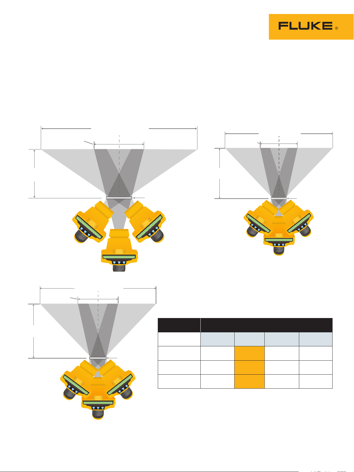
These Field of View (FOV) calculations are based on best practices used during infrared inspections and serve as a guide when
choosing IR Window sizes and locations.
Please note that the illustrations represent achievable FOV at a distance of 30.48 cm (12 in) to target. Additional FOV
calculations at various distances to target are given in the tables below. Actual FOV can vary based upon equipment layout
(phase barriers, internal compartments, etc.). Be sure to verify IR Window position before drilling holes for installation.
For illustration purposes, only horizontal FOV is shown. Adjusting the position of the thermal imager allows the overall
FOV to be achieved in all directions—360 degrees.
96.52 cm (38 in)
24.2 cm
(9.53 in)
22.1 cm
(8.7 in)
30.48 cm
(12 in)
30.48 cm
(12 in)
19.76 cm
(7.78 in)
38.1 cm (15 in)
100 mm (4 in)
window
50 mm (2 in)
window
IR window
size
100 mm (4 inch)
75 mm (3 inch)
50 mm (2 inch)
30.48 cm
(12 in)
15.24 cm
(6 in)
53.34 cm
(21 in)
40.64 cm
(16 in)
20.32 cm
(8 in)
Distance to target
30.48 cm
(12 in)
96.52 cm
(38 in)
73.66 cm
(29 in)
38.1 cm
(15 in)
45.72 cm
(18 in)
139.7 cm
(55 in)
109.22 cm
(43 in)
53.34 cm
(21 in)
75 mm (3 in)
window
60.96 cm
(24 in)
182.88 cm
(72 in)
142.24 cm
(56 in)
68.58 cm
(27 in)
All calculations based on Fluke Ti32 Thermal Imager with standard lens (23° x 17°).
Page 2
30.48 cm
(12 in)
40.89 cm
(16.1 in)
63.75 cm (25.1 in)
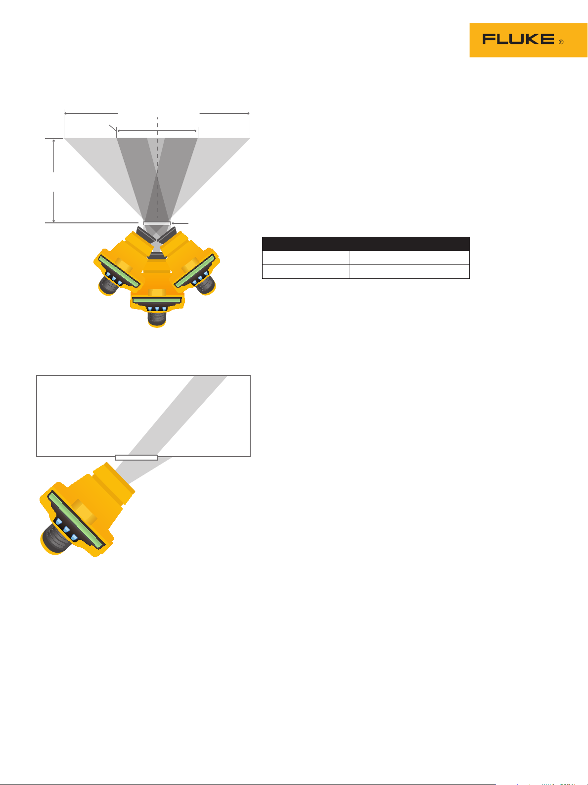
Wide-angle lenses
Compared to a standard lens (23° x 17°) a wide-angle lens (46° x 34°)
offers a larger FOV when positioned perpendicular to the IR Window, as
shown. However, the size of the wide-angle lens itself limits the ability
to position the thermal imager at much of an angle. This means that the
achievable FOV with a wide-angle lens, obtained by angling the thermal imager, is actually less than that of the standard lens. This can vary
based on camera model.
75 mm (3 in)
window
Calculations based on Fluke Ti32 with wide-angle lens (46° x 34°)
75 mm (3 in) wide-angle lenses
Distance to target 30.48 cm (12 in)
FOV 63.75 cm (25.1 in)
Extreme angles
A maximum attainable FOV (roughly 6xD) can be achieved by positioning
a thermal imager at extreme angles. These angles require that the view
through the thermal imager include seeing both through the IR Window
(inside the enclosure) and beyond the IR Window (outside the enclosure).
Such positioning does not expose the entire surface of the camera lens to
the target being measured and when combined with the steep viewing
angle, slightly less accurate results should be expected.
For more information on Fluke IR Windows,
call 1-800-760-4523 or visit www.fluke.com/irwindows
©2011 Fluke Corporation. Specifications subject to change without notice. Printed in U.S.A. 9/2011 4080700A F-EN-N
Modification of this document is not permitted without written permission from Fluke Corporation.
 Loading...