

Page 1

CuffLink
NIBP Analyzer
Operators Manual
PN 2242915
December 2007, Rev. 1, 9/09
© 2007, 2009 Fluke Corporation, All rights reserved. Printed in USA. Specifications subject to change without notice.
All product names are trademarks of their respective companies.
Page 2

Warranty and Product Support
Fluke Biomedical warrants this instrument against defects in materials and workmanship
for one year from the date of original purchase. During the warranty period, we will
repair or at our option replace, at no charge, a product that proves to be defective,
provided you return the product, shipping prepaid, to Fluke Biomedical. This warranty
covers the original purchaser only and is not transferable. The warranty does not apply if
the product has been damaged by accident or misuse or has been serviced or modified by
anyone other than an authorized Fluke Biomedical service facility. NO OTHER
WARRANTIES, SUCH AS FITNESS FOR A PARTICULAR PURPOSE, ARE
EXPRESSED OR IMPLIED. FLUKE SHALL NOT BE LIABLE FOR ANY SPECIAL,
INDIRECT, INCIDENTAL OR CONSEQUENTIAL DAMAGES OR LOSSES,
INCLUDING LOSS OF DATA, ARISING FROM ANY CAUSE OR THEORY.
This warranty covers only serialized products and their accessory items that bear a
distinct serial number tag. Recalibration of instruments is not covered under the warranty
This warranty gives you specific legal rights and you may also have other rights that vary
in different jurisdictions. Since some jurisdictions do not allow the exclusion or limitation
of an implied warranty or of incidental or consequential damages, this limitation of
liability may not apply to you. If any provision of this warranty is held invalid or
unenforceable by a court or other decision-maker of competent jurisdiction, such holding
will not affect the validity or enforceability of any other provision.
07/07
Page 3

Notices
All Rights Reserved
© Copyright 2007, Fluke Biomedical. No part of this publication may be reproduced, transmitted, transcribed, stored in a retrieval
system, or translated into any language without the written permission of Fluke Biomedical.
Copyright Release
Fluke Biomedical agrees to a limited copyright release that allows you to reproduce manuals and other printed materials for use in
service training programs and other technical publications. If you would like other reproductions or distributions, submit a written
request to Fluke Biomedical.
Unpacking and Inspection
Follow standard receiving practices upon receipt of the instrument. Check the shipping carton for damage. If damage is found, stop
unpacking the instrument. Notify the carrier and ask for an agent to be present while the instrument is unpacked. There are no special
unpacking instructions, but be careful not to damage the instrument when unpacking it. Inspect the instrument for physical damage such
as bent or broken parts, dents, or scratches.
Technical Support
For application support or answers to technical questions, either email techservices@flukebiomedical.com or call 1-800- 648-7952 or
1-425-446-6945.
Claims
Our routine method of shipment is via common carrier, FOB origin. Upon delivery, if physical damage is found, retain all packing
materials in their original condition and contact the carrier immediately to file a claim. If the instrument is delivered in good physical
condition but does not operate within specifications, or if there are any other problems not caused by shipping damage, please contact
Fluke Biomedical or your local sales representative.
Standard Terms and Conditions
Refunds and Credits
Please note that only serialized products and their accessory items (i.e., products and items bearing a distinct serial number
tag) are eligible for partial refund and/or credit. Nonserialized parts and accessory items (e.g., cables, carrying cases,
auxiliary modules, etc.) are not eligible for return or refund. Only products returned within 90 days from the date of original
purchase are eligible for refund/credit. In order to receive a partial refund/credit of a product purchase price on a serialized product, the
product must not have been damaged by the customer or by the carrier chosen by the customer to return the goods, and the product
must be returned complete (meaning with all manuals, cables, accessories, etc.) and in “as new” and resalable condition. Products not
returned within 90 days of purchase, or products which are not in “as new” and resalable condition, are not eligible for credit return and
will be returned to the customer. The Return Procedure (see below) must be followed to assure prompt refund/credit.
Restocking Charges
Products returned within 30 days of original purchase are subject to a minimum restocking fee of 15 %. Products returned in excess of
30 days after purchase, but prior to 90 days, are subject to a minimum restocking fee of 20 %. Additional charges for damage and/or
missing parts and accessories will be applied to all returns.
Return Procedure
All items being returned (including all warranty-claim shipments) must be sent freight-prepaid to our factory location. When you return
an instrument to Fluke Biomedical, we recommend using United Parcel Service, Federal Express, or Air Parcel Post. We also
recommend that you insure your shipment for its actual replacement cost. Fluke Biomedical will not be responsible for lost shipments
or instruments that are received in damaged condition due to improper packaging or handling.
Use the original carton and packaging material for shipment. If they are not available, we recommend the following guide for
repackaging:
Use a double-walled carton of sufficient strength for the weight being shipped.
Use heavy paper or cardboard to protect all instrument surfaces. Use nonabrasive material around all projecting parts.
Use at least four inches of tightly packed, industry-approved, shock-absorbent material around the instrument.
Returns for partial refund/credit:
Every product returned for refund/credit must be accompanied by a Return Material Authorization (RMA) number, obtained from our
Order Entry Group at 1-800-648-7952 or 1-425-446-6945.
Page 4

Repair and calibration:
To find the nearest service center, go to www.flukebiomedical.com/service
In the U.S.A.:
Cleveland Calibration Lab
Tel: 1-800-850-4606
Email: globalcal@flukebiomedical.com
Everett Calibration Lab
Tel: 1-888-993-5853
Email: service.status@fluke.com
In Europe, Middle East, and Africa:
Eindhoven Calibration Lab
Tel: +31-402-675300
Email: ServiceDesk@fluke.com
In Asia:
Everett Calibration Lab
Tel: +425-446-6945
Email: service.international@fluke.com
, or
Certification
This instrument was thoroughly tested and inspected. It was found to meet Fluke Biomedical’s manufacturing specifications when it
was shipped from the factory. Calibration measurements are traceable to the National Institute of Standards and Technology (NIST).
Devices for which there are no NIST calibration standards are measured against in-house performance standards using accepted test
procedures.
WARNING
Unauthorized user modifications or application beyond the published specifications may result in electrical shock hazards or
improper operation. Fluke Biomedical will not be responsible for any injuries sustained due to unauthorized equipment
modifications.
Restrictions and Liabilities
Information in this document is subject to change and does not represent a commitment by Fluke Biomedical. Changes made
to the information in this document will be incorporated in new editions of the publication. No responsibility is assumed by
Fluke Biomedical for the use or reliability of software or equipment that is not supplied by Fluke Biomedical, or by its
affiliated dealers.
Manufacturing Location
The CuffLink NIBP Analyzer is manufactured in Everett, Washington by Fluke Biomedical, 6920 Seaway Blvd., Everett,
WA, U.S.A.
Page 5

Table of Contents
Chapter Title Page
1 Introduction and Specifications......................................................... 1-1
Introduction........................................................................................................ 1-3
Standard Features............................................................................................... 1-4
New Features (Firmware Revision 3.0 and Later)............................................. 1-4
Arrhythmias................................................................................................... 1-4
Pressure Testing............................................................................................. 1-5
Remote Commands ....................................................................................... 1-6
General Safety Considerations........................................................................... 1-6
Symbols ......................................................................................................... 1-6
Warnings and Cautions.................................................................................. 1-7
Instrument Familiarity ....................................................................................... 1-8
Specifications..................................................................................................... 1-12
Accessories ........................................................................................................ 1-16
2 Operation ............................................................................................. 2-1
Powering Up the Analyzer................................................................................. 2-3
Menu Structure and Navigation ......................................................................... 2-3
Preliminary Procedures...................................................................................... 2-6
Assembling Equipment ................................................................................. 2-6
Making Connections...................................................................................... 2-8
Observing Results.......................................................................................... 2-9
Selecting Heart Rate (HtRate) ....................................................................... 2-10
Adjusting the Pressure Envelope (AdjEnv)................................................... 2-11
Simulating Adult Blood Pressure....................................................................... 2-14
Setting Zero Pressure..................................................................................... 2-15
Simulating Other ADAMS Family Target Values ........................................ 2-16
NIBP Monitor Testing Sequence................................................................... 2-16
Simulating Neonatal Blood Pressure ................................................................. 2-17
Simulating Arrhythmias..................................................................................... 2-18
Pressure Testing................................................................................................. 2-19
Leak Testing .................................................................................................. 2-19
Manometer Function ..................................................................................... 2-20
Pop Off Test .................................................................................................. 2-21
Utility Functions ................................................................................................ 2-22
i
Page 6

Cufflink
Operators Manual
Set Clock ....................................................................................................... 2-22
Pop Time ....................................................................................................... 2-24
Logo............................................................................................................... 2-25
System Functions........................................................................................... 2-25
Establishing Communications ........................................................................... 2-31
Configuring RS232........................................................................................ 2-31
Testing the RS232 Port and Connections ...................................................... 2-32
Using Auto Sequences ....................................................................................... 2-33
Executing an Auto Sequence......................................................................... 2-33
Utilities .......................................................................................................... 2-34
Printing Documents ........................................................................................... 2-37
Printing Blood Pressure Test Results ............................................................ 2-37
Printing Manometer, Leak Test, and Overpressure Test Results .................. 2-38
Printing Auto Sequences ............................................................................... 2-38
3 Remote Operation ............................................................................... 3-1
Introduction........................................................................................................ 3-3
Setting Up the medTester .................................................................................. 3-3
Remote Command Syntax ................................................................................. 3-4
Command Syntax for medTester................................................................... 3-4
Command Syntax for Computer.................................................................... 3-4
Command Parameters.................................................................................... 3-4
Terminating Characters ................................................................................. 3-5
Error Messages .............................................................................................. 3-5
Command Descriptions...................................................................................... 3-7
BEEP ............................................................................................................. 3-7
CALPUCKPOS ............................................................................................. 3-8
DEFLATE ..................................................................................................... 3-8
DRAWENV................................................................................................... 3-8
DRAWENVNEO .......................................................................................... 3-11
DRAWPULSE............................................................................................... 3-15
GLOBALINIT............................................................................................... 3-17
GOTOLOCAL............................................................................................... 3-18
IDENT ........................................................................................................... 3-18
INFLATE ...................................................................................................... 3-18
KEYTEST ..................................................................................................... 3-19
LEAKTEST................................................................................................... 3-19
MAKEARM .................................................................................................. 3-20
MAKEARMNEO .......................................................................................... 3-23
MANOMETER ............................................................................................. 3-27
MKARM10.................................................................................................... 3-27
MKARM20.................................................................................................... 3-27
MKARM30.................................................................................................... 3-28
MKARM40.................................................................................................... 3-28
MKARM50.................................................................................................... 3-28
MKARM60.................................................................................................... 3-28
MKARM70.................................................................................................... 3-29
MKARMNEO10 ........................................................................................... 3-29
MKARMNEO20 ........................................................................................... 3-29
MKARMNEO30 ........................................................................................... 3-29
MKARMNEO40 ........................................................................................... 3-30
MKARMNEO50 ........................................................................................... 3-30
MKARR_AF ................................................................................................. 3-30
MKARR_MB ................................................................................................ 3-30
ii
Page 7

Contents (continued)
MKARR_PAC............................................................................................... 3-31
MKARR_PVC............................................................................................... 3-31
MKARR_AS ................................................................................................. 3-31
POPOFF ........................................................................................................ 3-32
PRINTTEST .................................................................................................. 3-32
PSCALE ........................................................................................................ 3-33
PULSE........................................................................................................... 3-34
PUMPPCB..................................................................................................... 3-36
RCUSERENV ............................................................................................... 3-36
RDCLOCK.................................................................................................... 3-36
RDENVGAIN ............................................................................................... 3-36
RDENVSHIFT .............................................................................................. 3-37
RDPEAKDIV................................................................................................ 3-37
RDQCDATE ................................................................................................. 3-37
RDUSERENV ............................................................................................... 3-37
READPRESS ................................................................................................ 3-38
RESET........................................................................................................... 3-38
STUSERENV................................................................................................ 3-39
WRCLOCK ................................................................................................... 3-39
WRPEAKDIV ............................................................................................... 3-40
WRUSERENV .............................................................................................. 3-40
ZEROPRESS................................................................................................. 3-41
Programming with Analyzer Commands........................................................... 3-41
Checklist Generated in BASIC...................................................................... 3-41
Adult BP Checklists and Test Results ........................................................... 3-43
Neonate BP Checklists and Test Results....................................................... 3-47
Adult Arrhythmic BP Checklists and Test Results........................................ 3-51
Additional Command Descriptions (Firmware Version 3.20)........................... 3-55
PUMPON ...................................................................................................... 3-55
PUMPOFF..................................................................................................... 3-55
VALVEOPEN ............................................................................................... 3-55
VALVECLOSED .......................................................................................... 3-56
4 Maintenance, Service, and Calibration.............................................. 4-1
Maintenance....................................................................................................... 4-3
Avoiding Damage.......................................................................................... 4-3
Cleaning......................................................................................................... 4-3
Service and Calibration...................................................................................... 4-3
Appendices
A Non-Invasive Blood Pressure (NIBP) Monitoring Tutorial ........................ A-1
B Glossary....................................................................................................... B-1
iii
Page 8

Cufflink
Operators Manual
iv
Page 9

List of Tables
Table Title Page
1-1. New RS232 Remote Commands............................................................................ 1-6
1-2. Symbols.................................................................................................................. 1-6
1-3. Analyzer Top and Front Panel Controls and Indicators ......................................... 1-8
1-4. Rear Panel Controls and Indicators........................................................................ 1-11
1-5. Standard Accessories ............................................................................................. 1-16
2-1. Blood Pressure Parameters Provided by the Select BP Option.............................. 2-6
2-2. Measured Test Parameters ..................................................................................... 2-10
2-3. Arrhythmia Types .................................................................................................. 2-18
2-4. Leak Test Utility Options....................................................................................... 2-20
2-5. Measured Leak Test Parameters ............................................................................ 2-20
2-6. Measured Manometer Parameters.......................................................................... 2-21
2-7. Measured Pop Off Test Parameters........................................................................ 2-22
2-8. Speaker Tests and Adjustments.............................................................................. 2-27
2-9. Display Test Descriptions ...................................................................................... 2-28
2-10. Pop Time and Comm Port Default Values ............................................................. 2-29
2-11. Auto Sequence Defaults ......................................................................................... 2-30
2-12. RS232 Settings ....................................................................................................... 2-32
3-1. medTester Remote Configuration Settings ............................................................ 3-3
3-2. Available Error Messages ...................................................................................... 3-6
3-3. Autosequence Defaults........................................................................................... 3-17
3-4. Pop Time and Comm Port Default Values............................................................. 3-17
v
Page 10

Cufflink
Operators Manual
vi
Page 11

List of Figures
Figure Title Page
1-1. CuffLink Non-Invasive Blood Pressure Analyzer ................................................. 1-3
1-2. Cuff pressure waveform during blood pressure measurement............................... 1-4
1-3. Analyzer Top and Front Panel Controls and Indicators ......................................... 1-8
1-4. Rear Panel Controls and Indicators........................................................................ 1-11
2-1. Analyzer Menu Map .............................................................................................. 2-4
2-2. Adjustments for Adult Cuff Mandrel..................................................................... 2-7
2-3. Neonate Mandrel.................................................................................................... 2-7
2-4. NIBP Test System Diagram ................................................................................... 2-8
2-5. Makearm Display of Test Results .......................................................................... 2-9
2-6. Sample Printout of Auto Sequence Content........................................................... 2-36
2-7. Sample Printout of Adams Adult Family 120/80 Test Results .............................. 2-38
2-8. Sample Printout of Manometer Test Results.......................................................... 2-38
2-9. Sample Printout of Leak Test Results .................................................................... 2-38
2-10. Sample Printout of Overpressure Test Results....................................................... 2-38
2-11. Sample Printout of Adult Auto Sequence Content................................................. 2-40
2-12. Sample Printout of Adult Auto Sequence Test Results.......................................... 2-41
2-13. Sample Printout of Adult BP with Arrhythmia Auto Sequence Content ............... 2-42
2-14. Sample Printout of Adult BP with Arrhythmia Auto Sequence Test Results ........ 2-43
2-15. Sample Printout of Neonate Auto Sequence Content ............................................ 2-44
2-16. Sample Printout of Neonate Auto Sequence Test Results ..................................... 2-46
3-1. Analyzer Adult Blood Pressure Envelope (BP = 120/80)...................................... 3-8
3-2. Analyzer Neonate Blood Pressure Envelope (BP = 120/80).................................. 3-11
3-3. Analyzer Pressure Pulse #3 .................................................................................... 3-15
3-4. POPOFF Command Display .................................................................................. 3-32
3-5. Scale Pulse Amplitude Display.............................................................................. 3-33
3-6. A BASIC Program using Analyzer Remote Commands........................................ 3-42
3-7. medBase Adult BP Checklist ................................................................................. 3-43
3-8. medBase Adult BP Test Results............................................................................. 3-44
3-9. Sentinel Adult BP Checklist................................................................................... 3-45
3-10. Sentinel Adult BP Test Results .............................................................................. 3-46
3-11. medBase Neonate BP Checklist............................................................................. 3-47
3-12. medBase Neonate BP Test Results ........................................................................ 3-48
3-13. Sentinel Neonate BP Checklist .............................................................................. 3-49
3-14. Sentinel Neonate BP Test Results .......................................................................... 3-50
3-15. medBase Adult Arrhythmic BP Checklist.............................................................. 3-51
vii
Page 12

Cufflink
Operators Manual
3-16. medBase Adult Arrhythmic BP Test Results......................................................... 3-52
3-17. Sentinel Adult Arrhythmic BP Checklist ............................................................... 3-53
3-18. Sentinel Adult Arrhythmic BP Test Results........................................................... 3-54
viii
Page 13

Chapter 1
Introduction and Specifications
Title Page
Introduction........................................................................................................ 1-3
Standard Features............................................................................................... 1-4
New Features (Firmware Revision 3.0 and Later)............................................. 1-4
Arrhythmias................................................................................................... 1-4
Pressure Testing............................................................................................. 1-5
Remote Commands ....................................................................................... 1-6
General Safety Considerations........................................................................... 1-6
Symbols ......................................................................................................... 1-6
Warnings and Cautions.................................................................................. 1-7
Instrument Familiarity ....................................................................................... 1-8
Specifications..................................................................................................... 1-12
Accessories ........................................................................................................ 1-16
1-1
Page 14

Cufflink
Operators Manual
1-2
Page 15

Introduction and Specifications
Introduction 1
Introduction
The CuffLink Non-Invasive Blood Pressure Analyzer, hereafter referred to as the
Analyzer, provides accurate and repeatable dynamic blood pressure (BP) waveforms for
evaluation of both semi and fully automated oscillometric non-invasive blood pressure
(NIBP) devices. The Analyzer is shown in Figure 1-1.
CuffLink
NON-INVASIVE BLOOD PRESSURE ANA
LYZER
ESC
F1
F2
F3
F4
F5
BEEPER
V
OLUM
ENT
DISPL
E
AY
VIEW
Max
Da
r
k
fcv001.eps
CUFF
CONNECT
mmHg
CUFF
mmHg
OUTPUTS
PULSE
mHg
DC
Figure 1-1. CuffLink Non-Invasive Blood Pressure Analyzer
To test a device, wrap the BP cuff around the supplied mandrel and insert the cuff adapter
in the pressurized line. All tests are conducted with the BP cuff connected to the system.
The Analyzer can generate BP waveforms for seven adult (oscillometric), five neonate
(oscillometric), and 5 arrhythmias. The different systolic/diastolic pressure gradients
simulate a physiological range of normal, hypotensive, and hypertensive adult or neonate
patients. Actual patient data was used to design the preprogrammed peripheral pulse
waveforms and envelopes.
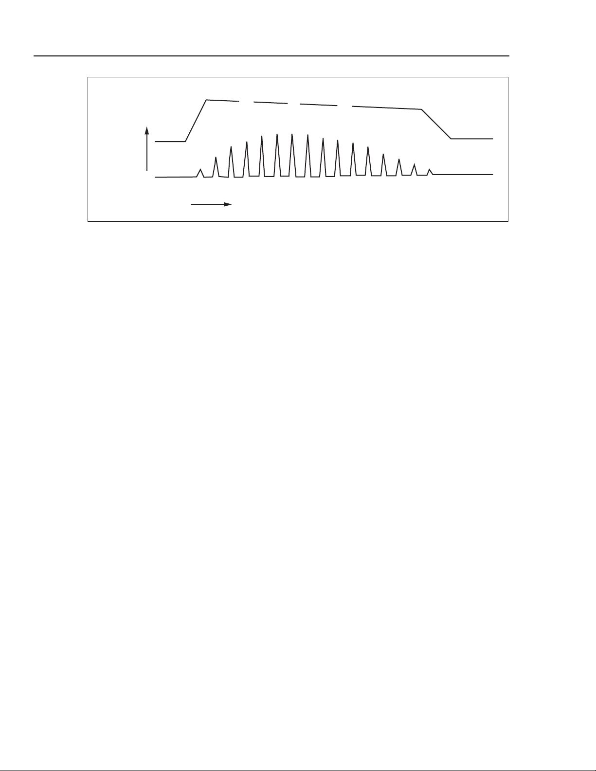
The Analyzer can produce qualitative measurements of BP cuff pressure and inflate /
deflate timing, as shown in Figure 1-2.
1-3
Page 16
Cufflink
Operators Manual
CUFF
PRESSURE
TIME
Figure 1-2. Cuff pressure waveform during blood pressure measurement
The Analyzer also offers automated leak testing of NIBP monitors. An internal pump
pressurizes the NIBP system under test. Press a key to initiate a 60 second leak test once
the desired pressure is reached. Use the Analyzer’s digital manometer instead of a
mercury column for doing pressure measurements. The Analyzer facilitates overpressure
testing of NIBP monitors by automatically detecting and displaying the overpressure
point.
Standard Features
The Analyzer has the following standard features:
• Dynamic oscillometric noninvasive blood pressure simulation
SYS
OSCILLATION AMPLITUDE
MAP
DIA
fcv002.eps
• Automated static pressure measurements, leakage testing, and relief-valve testing
• Five automated NIBP testing autosequences
• Five arrhythmia selections
• Adult and neonatal NIBP selections
• Direct interface with medTester 5000C
• Adjustable heart rate values
• Calendar clock with battery backup
• Internal PCB expansion slot
New Features (Firmware Revision 3.0 and Later)
Firmware revision 3.0 included the following additions and updates, including a set of
adult arrhythmias, an internal pump, and additions to pressure testing.
Arrhythmias
The Analyzer features five new arrhythmias to test NIBP monitors in the presence of
typical patient arrhythmias. These clinically derived simulations are representations of
the peripheral pulse, as seen by an oscillometric NIBP monitor.
Each arrhythmia is generated on a random basis throughout the entire pressure curve
cycle. The variations in pulse timing and amplitude are relatively small.
1-4
Page 17

Introduction and Specifications
New Features (Firmware Revision 3.0 and Later) 1
Premature Atrial Contraction (PAC)
The first pulse of the PAC cycle is premature and lower in amplitude than a normal sinus
pulse. The next pulse would be back in sync with normal sinus and slightly higher in
amplitude. All subsequent pulses are normal.
Premature Ventricular Contraction (PVC)
This is a representation of the peripheral pulse similar to PAC
Atrial Fibrillation (AF)
The AF cycle has an irregular R to R interval. Its occurrence and properties (early vs.
late) are random throughout the pressure curve cycle.
Missed Beat (MB)
A complete beat is randomly skipped during the pressure curve cycle. The following beat
reverts to normal R to R intervals.
Aberrant Sinus Conduction (AS)
The AS cycle inserts one pulse so low that it is virtually non-existent. This causes the
Analyzer to skip one diastolic pulse and then return to normal sinus pulses.
Pressure Testing
The Analyzer now has the following enhancements to its pressure testing capability.
Internal Pump
The Analyzer now has an internal compressor which eliminates the need to manually
inflate the cuff for NIBP monitor testing. This automates static pressure measurements,
leak testing, and relief valve testing.
Pop Off Added to Press Menu
Perform over-pressure tests on NIBP monitors with this addition to the PRESS menu.
Utility Menu Added to Leak Test
Select cuff size, turn printing on or off, and choose a target pressure for leak testing.
Manometer
The Analyzer simulates a digital manometer with pump capabilities.
1-5
Page 18

Cufflink
Operators Manual
Remote Commands
Table 1-1 lists new CuffLink RS232 commands to support new functions.
Table 1-1. New RS232 Remote Commands
Command Function
DEFLATE Releases pressure inside CuffLink
INFLATE Pumps CuffLink to 200 mmHg or specified pressure
KEYTEST Tests CuffLink's keyboard
MKARR_AF Simulates atrial fibrillation
MKARR_MB Simulates a missed beat
MKARR_PAC Simulates premature atrial contraction
MKARR_PVC Simulates premature ventricular contraction
MKARR_AS As Simulates aberrant sinus conduction
POPOFF Tests monitor's overpressure valve
PUMPPCB Determines if pump PCB is installed in CuffLink
General Safety Considerations
Read the Users Manual before operating the Analyzer.
Symbols
Table 1-2 describes the symbols associated with the Analyzer.
Table 1-2. Symbols
Symbol Description
X Hazardous voltage
W Important information; refer to manual.
Œ
P Conforms to European Union directives
~
Hg Contains mercury. Dispose properly.
Conforms to UL Std 3101-1; certified to CAN/USA Std C22.2 No.
1010.1
Do not dispose of this product as unsorted municipal waste. Go
to Fluke’s website for recycling information.
1-6
Page 19

Introduction and Specifications
General Safety Considerations 1
Warnings and Cautions
A Warning identifies hazardous conditions and actions that could cause bodily harm or
death.
A Caution identifies conditions and actions that could damage the Analyzer, the
equipment under test, or cause permanent loss of data.
XW Warning
To avoid possible electrical shock or personal injury, follow
these guidelines:
• Use this Analyzer only in the manner specified by the
manufacturer.
• Do not use the product if it operates abnormally.
• Do not connect the Analyzer to a patient or equipment
connected to a patient. The Analyzer is intended for
equipment evaluation only and should never be used in
diagnostics, treatment or in any other capacity where the
Analyzer would come in contact with a patient.
• Do not use the product in wet locations, around explosive
gases or dust.
• Never open the Analyzer's case. Dangerous voltages are
present. There are no user replaceable parts in the
Analyzer.
• Have the Analyzer serviced only by qualified personnel.
• The Analyzer must be properly earthed. Only use a supply
socket that has a protective earth contact. If there is any
doubt as to the effectiveness of the supply socket earth, do
not connect the Analyzer.
• Do not use a two-conductor adapter or extension cord; this
will break the protective ground connection.
W Caution
To avoid damage to the Analyzer or adverse affects on its
performance, follow these guidelines:
• Do not expose the system to temperature extremes. Ambient
temperatures should remain between 0 °C and 50 °C. System
performance may be adversely affected if temperatures fluctuate
above or below this range.
• Clean the Analyzer only by wiping it down with a clean, lint-free
cloth dampened with a mild detergent solution. Do not spray
liquid directly on or immerse the unit.
1-7
Page 20
Cufflink
Operators Manual
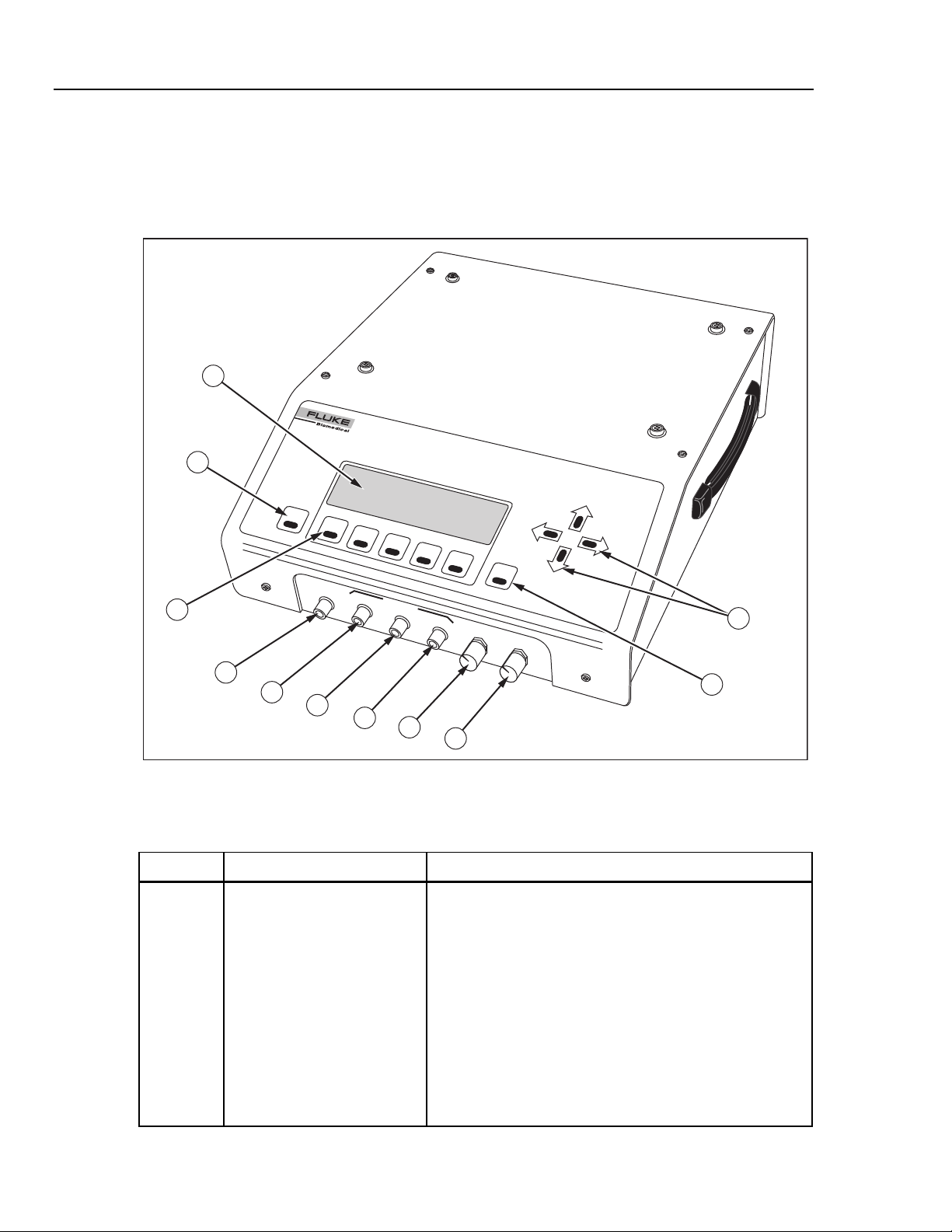
Instrument Familiarity
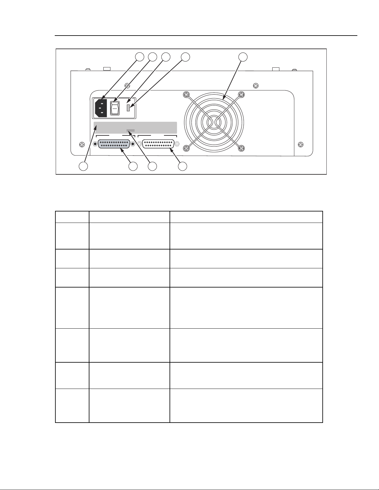
Figure 1-3 shows the top and front panel controls and indicators of the Analyzer.
Table 1-3 lists these components with accompanying descriptions. Figure 1-4 shows the
rear panel controls and indicators, and Table 1-4 lists and describes these components.
1
CuffLink
NON-INVASIVE BLOOD PRESSURE ANA
L
YZE
R
2
ESC
F1
F2
F3
F4
F5
BEEPER
V
OLUM
ENT
11
DISPL
E
AY
VIEW
Max
Da
r
k
10
CUFF
CONNECT
CUFF
OUTPUTS
mmHg
PULSE
mHg
DC
3
mmHg
4
5
6
7
8
9
Figure 1-3. Analyzer Top and Front Panel Controls and Indicators
Table 1-3. Analyzer Top and Front Panel Controls and Indicators
Label Component Description
A Display The LCD (Liquid Crystal Display) is a full alphanumeric and
graphic display. The maximum number of characters able
to be on a single line at any given time is 40, and the
number of lines from top to bottom is 8, thereby producing a
possible 320 character display. The graphics mode of the
display is defined by a grid of 64 vertical pixels by 240
horizontal pixels. This mode enables display of the cuff
pressure waveform.
fcv003.eps
1-8
Display viewing angle is adjustable, so if the display appears
blank (view angle set too low), or dark (view angle set too
high) the view angle may need to be adjusted for optimum
visibility (see Display View Control Knob).
Page 21

Introduction and Specifications
Table 1-3. Analyzer Top and Front Panel Controls and Indicators (cont.)
Label Component Description
Instrument Familiarity 1
B Esc Key The Esc (escape) key enables the user to exit any menu,
exit without saving new data, or abort any function of
CuffLink. Continuously holding down the Esc key will return
the user to the CuffLink logo display from any menu.
C Function Keys The function keys are labeled Fl through F5. Pressing any
one of these keys will execute the function, defined by
software, that is displayed above that particular key.
D Cuff Connect A quick disconnect type of port provides the output
connection from the pulse producing motor inside Cufflink,
to the line connecting the cuff and the BP patient monitor.
E Cuff Output This is a voltage output proportional to cuff pressure
(10mv/mmHg). It is always active with a range of -5 V dc to
+5 V dc (-500 mmHg to +500 mmHg). The accuracy is
specified for positive pressures only.
Example:
1.0 V = 100 mmHg
2.5 V = 250 mmHg
This signal is also useful when connected to a storage
oscilloscope or strip recorder to observe the cuff
inflate/deflate cycle.
Output impedance is 100 Ω.
F Pulse output This is a voltage output proportional to pulse pressure. It is
only active when Cufflink is outputting pressure pulses. The
output is at 0 V in the inactive state. The pulse voltage is
taken from the pressure transducer and the large static cuff
pressure is subtracted. For example, if the cuff is inflated to
150 mmHg and the pulse is 1.2 mmHg in amplitude, only the
1.2 mmHg portion of the signal is presented at this output.
The pulse output voltage is 1 V dc/mmHg and has a range
of -5 VDC to +5 VDC (-5 mmHg to +5 mmHg).
Example:
1.0 V = 1.0 mmHg pulse
0.5 V = 0.5 mmHg pulse
When Cufflink is simulating blood pressure it removes the
static cuff pressure from the pulse output (forcing it to 0
VDC) at the beginning of each heartbeat. During the
heartbeat the amplitude of the pulse is output. As the cuff
deflates (or inflates) this process is repeated for each
heartbeat.
Output impedance is 100 Ω.
1-9
Page 22

Cufflink
Operators Manual
Table 1-3. Analyzer Top and Front Panel Controls and Indicators (cont.)
Label Component Description
G Sync Output This is a logic level (0 to 5VDC) that outputs a pulse at the
start of every heartbeat. When CuffLink is not outputting
pressure pulses this output is at OVDC. When CuffLink is
outputting pressure pulses the output is high (5VDC) during
the pulse and low between the end of one pulse and the
start of the next pulse. This output is useful for measuring
heart rate and synchronizing a scope trigger for viewing
individual pressure pulses on the pulse output.
Output impedance is 100 Ω.
H Beeper Volume Control Knob The amplitude of the CuffLink audible feedback may be
adjusted by turning the beeper volume control knob. Turning
the knob clockwise (towards the MAX label next to the knob)
will increase the volume of the beeper, while turning the
knob counterclockwise will decrease the beeper volume.
I Display View Control Knob The angle at which the display is most visible is adjustable
with the display view control knob. Turning the knob
clockwise (towards the DARK label next to the knob) will
increase the contrast of the display, or make the display
darker. Turning the knob counterclockwise will decrease the
contrast, making the display lighter.
J Ent Key Pressing the Ent (enter) key will select a highlighted menu,
initiate a CuffLink function, or store data in EEROM. In
effect, the enter key is the opposite of the Esc key.
K Arrow keys The arrow keys are the cursor control keys. Pressing the up
arrow key moves the cursor on the display in a upward
direction or increases the highlighted value. Pressing the
down arrow key moves the cursor on the display in a
downward direction or decreases the highlighted value. The
down arrow key is also capable of pulling down the
submenus of a highlighted main menu. Pressing the left or
right arrow keys will produce cursor movement in the
corresponding direction. Holding any arrow key down
continuously will cause a repeating of the action of that key.
L Handle The handle for transporting CuffLink is located on the right
side of the instrument case.
1-10
Page 23
Introduction and Specifications
1
2
3
115
I
O
4 5
CuffLink sn 3480
Instrument Familiarity 1
FUSE T3.15a 100-115 VAC 50/60Hz
FUSE T1A 200-230 VAC 50/60Hz
SERIAL NUMBER
PRINTER
3480
INPUT POWER 60 VA
FLUKE BIOMEDICAL CORPORATION
CARSON CITY, NEVADA
MADE IN THE U.S.A
RS232
679 8
Figure 1-4. Rear Panel Controls and Indicators
fcv004.eps
Table 1-4. Rear Panel Controls and Indicators
Label Component Description
A Power Cord Input The input for the Cufflink power cord is located next to the
power switch. This is the connection for the detachable
power cord.
B Power Switch The on position of the power switch is represented by 1 and
the off position is labeled 0.
C Fuse Cover The fuse(s) are located behind the fuse cover. The fuse
cover may be carefully pried open at 3a.
D Voltage Selector CuffLink is able to operate on two different line voltages.
The voltage selector indicates the voltage (either 120V or
240V) at which CuffLink will operate. There are an
additional two voltages (100V and 220V) listed on the back
panel. These do not apply to CuffLink.
E Fan Intake A hole cut in the rear panel of the case provides ventilation
for Cufflink from the fan. Care should be exercised not to
block the fan intake or to insert anything into the metal
protector.
F RS232 Port This is the connector for the RS-232 serial interface. It
is a 25 pin (DB25), male, D shell connector (same
pinout as PC compatible computer).
G Printer Port The connector for the parallel printer is a 25 pin
(DB25), female, D shell connector. The printer port is
Centronics compatible (same pinout as a PC
compatible computer).
1-11
Page 24

Cufflink
Operators Manual
Table 1-4. Rear Panel Controls and Indicators
Label Component Description
H Serial Port The four digit Cufflink serial number is located above
the printer port. The serial number should be
documented along with the model number whenever
Cufflink is shipped to Dynatech Nevada.
I Fuse Label The fuse label documents the type of fuses needed.
Use one 1ASB 250 V ac fuse (DNI part no. 1005-
0184) if Cufflink is set for 120 V operation, and two
1/2 A 250 V ac fuses (DNI part no. 1005-0185) if
Cufflink is set for 240 V operation.
Replacing Fuses
1. Turn Cufflink's power off and unplug the power cord.
2. Remove the fuse cover with a small blade screwdriver.
The plastic fuse holder should pop out of the Cufflink
case.
3. Use the screwdriver to pry the old fuse out of the plastic
holder.
4. Install the new fuse.
5. Replace the fuse holder by simply pushing the fuse
holder back into place.
Specifications
The following are general and electrical specifications for the Analyzer.
Physical Dimensions
Size ......................................................................... Width 12.5 inches
Weight..................................................................... 15 pounds
Power Requirements
Power ..................................................................... 120/250 V ac
Input voltage range...................................................... 60 VA
Fuses ...................................................................... T3.15a 110-115 V ac 50/60 Hz
Environmental Conditions
Operating Temperature........................................... 15 °C to 40 °C
Storage Temperature.............................................. -20 °C to +65 °C
Relative Humidity.................................................... 90 % max
Height 5.0 inches
Length 15.0 inches
50 Watts average
100 Watts peak
50/60 Hz
T1A 200-300 V ac 50/60 Hz
1-12
Page 25

Introduction and Specifications
Specifications 1
Display
Alphanumeric and Graphic LCD Display
Alphanumeric Mode............................................ 8 lines by 40 characters
Graphics Mode ................................................... 64 vertical by 240 horizontal dot matrix
Illumination.............................................................. Backlight with Viewing Angle Adjustment
Displayed Graphics................................................. Dynamic real-time NIBP cuff-pressure waveform, programmed
peripheral pulse and envelope waveforms
Control Keys
Function Keys ........................................................ F1 to F5
Cursor .................................................................... Up
Enter
Escape
Down
Left
Right
Parameter Selections
Menus ..................................................................... Pull down with on-screen help
Function keys.......................................................... Software defined, F1 to F5
Storage
Environment............................................................ Store in a dry area, temperature range of 32°F to 122°F.
Inspection or maintenance during storage.............. None required
Digital Interfaces
RS232/Serial........................................................... Baud Rates: 300, 600, 1200, 2400, 4800, 9600
Parallel Port (Printer) .............................................. Centronics compatible
Pulse Sync .............................................................. 0 to 5 V dc (TTL)
Stop Bits: 1, 2
Parity: Odd, Even, Off
Handshake: Xon/Xoff, RTS/CTS, None
Target Blood Pressure Selections
Select BP
Target Value (MAP)
(mmHg)
Adult 60/30 (40)
80/50 (62)
100/65 (75)
120/80 (90)
150/100 (115)
200/150 (165)
255/195 (215)
Neonate 60/30 (40)
80/50 (62)
100/65 (75)
120/80 (90)
150/100 (115)
Arrhythmias 120/80 (90) 80 Premature Atrial Contraction
HR
(BPM)
30
40
60
120
160
200
240
30
40
60
120
160
200
240
Waveform Type
Normal Sinus
Normal Sinus
Premature Ventricular Contraction
Atrial Fibrillation
Missed Beat
Aberrant Sinus Conduction
1-13
Page 26

Cufflink
Operators Manual
Preprogrammed Pulse Envelope
Horizontal Axis (cuff pressure) ............................... 0 to 300 mmHg in 1.0 mmHg steps
Vertical Axis ............................................................ 2.0 mmHg (nominal)
Pulse Amplitude (adult) .......................................... 2.0 mmHg @ MAP 100% gain
Repeatability ........................................................... ±1 % of selected target value
Pulse Waveforms
100% gain with normal adult cuff
0 to 2% selectable
Pulse ID # Pulse Width (ms) Rise Time (ms)
0 800 270
1 500 165
2 250 85
3 720 90
4 230 80
5 280 96
6 350 100
7 480 108
8 980 180
9 1980 460
10 1480 330
Digital Manometer
Pressure Range ...................................................... Maximum = 499.75 mmHg
Measurement Parameters ...................................... Instantaneous and peak
Pump....................................................................... 2.0 liter/minute minimum (free flow)
Automated Leak Testing
Start Pressure ......................................................... Maximum = 499.75 mmHg
Elapsed Time .......................................................... Fixed at 60 seconds
Leak Rate Range .................................................... 0.25 to 499.75 mmHg/minute
Pump....................................................................... 2.0 liter/minute minimum (free flow)
Monitor Pop-off Relief Valve Testing
Measurement Parameters ...................................... Instantaneous and peak pressure
Maximum Pressure ................................................. 499.75 mmHg
Accuracy
Dynamic NIBP Response Repeatability
(Systolic/Diastalic/Mean)......................................... ±1 % of Target Value
Cuff Pressure .......................................................... ±1.0 % of reading (±1 mmHg)
Input Overpressure Limit......................................... ±1500 mmHg
1-14
Page 27

Introduction and Specifications
Specifications 1
Ranges for MAKEARM Test Values
On Line Cuff Pressure ............................................ 0.0 to 500 mmHg on display
Peak Cuff Pressure................................................. 500 mmHg peak
Inflate Time ............................................................. 0.1 to 999.9 seconds
Inflate Rate.............................................................. 0.1 to 999.9 mmHg/second
Deflate Time............................................................ 0.1 to 999.9 seconds
Deflate Rate ............................................................ 0.1 to 999.9 mmHg/second
Total Measurement Time ........................................ 999.9 seconds maximum
Heart Rate............................................................... 30
0.0 to 300 mmHg on graph
40
60
80
120
160
200
240
Analog Outputs
Cuff Pressure .......................................................... 0 to 499.75 mmHg FS, ±1.0 % of reading,
Pulse Pressure........................................................ 0 to 5.0 mmHg FS, ±1.0 % of reading
±±.0 mmHg (cuff)
10 mV/mmHg
1.0 V/mmHg
Mandrels
Adult........................................................................ Five interlocking plastic blocks that produce four circumferences;
Large Adult................................................................ 39.5 cm; use all blocks
Adult.................................................................... 33 cm; use 2 curved end blocks and 2 rectangle blocks
Small Adult.......................................................... 26.6 cm; use 2 curved end blocks and 1 rectangle block
Child.................................................................... 20 cm; use 2 curved end blocks
Neonate .................................................................. One plastic truncated cylinder that accommodates three different
circumferences: 14 cm, 10 cm, and 7.6 cm; maximum cuff width of
7.6 cm.
a maximum cuff width of 15.25 cm:
1-15
Page 28

Cufflink
Operators Manual
Accessories
Soft vinyl accessory pouch 2248408
Operators Manual 2242915
Hospital grade power cord set 2198846
Adult cuff mandrel spacer blocks 2392381
Table 1-5 lists standard accessories provided with the Analyzer.
Table 1-5. Standard Accessories
Accessory Part Number
Cuff/hose adapters (8)
Male/Female LUER Locking
Female/Mole LUER Non-Locking Taper
5/32" Male/Male Hose Barb
¼” Male/Male Hose Barb
1/8" Male/Male Hose Barb
Male/Female Clippard (Critikon, Siemens)
Colder/CPC (Marquette, Protocol)
OBAC Quick Release (Hewlett Packard)
Adult cuff mandrel end blocks (two required) 2230305
External cuff mandrel neonatal (truncated plastic
cylinder diameters: 7, 6, 10, and 14 cm)
2242233
2242225
2242257
2242284
2242240
2242190
2242202
2242216
2392328
1-16
Page 29

Chapter 2
Operation
Title Page
Powering Up the Analyzer................................................................................. 2-3
Menu Structure and Navigation ......................................................................... 2-3
Preliminary Procedures...................................................................................... 2-6
Assembling Equipment ................................................................................. 2-6
Making Connections...................................................................................... 2-8
Observing Results.......................................................................................... 2-9
Selecting Heart Rate (HtRate) ....................................................................... 2-10
Adjusting the Pressure Envelope (AdjEnv)................................................... 2-11
Simulating Adult Blood Pressure....................................................................... 2-14
Setting Zero Pressure..................................................................................... 2-15
Simulating Other ADAMS Family Target Values ........................................ 2-16
NIBP Monitor Testing Sequence................................................................... 2-16
Simulating Neonatal Blood Pressure ................................................................. 2-17
Simulating Arrhythmias..................................................................................... 2-18
Pressure Testing................................................................................................. 2-19
Leak Testing .................................................................................................. 2-19
Manometer Function ..................................................................................... 2-20
Pop Off Test .................................................................................................. 2-21
Utility Functions ................................................................................................ 2-22
Set Clock ....................................................................................................... 2-22
Pop Time ....................................................................................................... 2-24
Logo............................................................................................................... 2-25
System Functions........................................................................................... 2-25
Establishing Communications ........................................................................... 2-31
Configuring RS232........................................................................................ 2-31
Testing the RS232 Port and Connections ...................................................... 2-32
Using Auto Sequences ....................................................................................... 2-33
Executing an Auto Sequence......................................................................... 2-33
Utilities .......................................................................................................... 2-34
Printing Documents ........................................................................................... 2-37
Printing Blood Pressure Test Results ............................................................ 2-37
Printing Manometer, Leak Test, and Overpressure Test Results .................. 2-38
Printing Auto Sequences ............................................................................... 2-38
2-1
Page 30

Cufflink
Operators Manual
2-2
Page 31

Operation
Select BP
ADAMS Adult
Powering Up the Analyzer 2
Powering Up the Analyzer
To power up the Analyzer, follow these directions:
1. Attach the supplied power cord to the power cord input on the back panel.
2. Plug the unit into a properly rated outlet.
3. Turn the Analyzer on by pushing the power switch on the back panel to the ON
position (marked I). The Analyzer performs a self test and system initialization,
during which the logo display is visible for about five seconds:
16:15:36
09/19/07
CuffLink
3.21, Pump
Non-Invasive Blood Pressure Analyzer
F1 F2 F3 F4 F5
The current time and date is in the upper right hand corner, and the software revision,
along with installed options, appears directly below the Analyzer name. After the
five-second logo display, the Main Menu displays:
Press Util Comm Auto
ADAMS Adult
ADAMS Neonate
Arrythmias
Select adult ADAMS family blood pressure
F1 F2 F3 F4 F5
Menu Structure and Navigation
The Main Menu options listed across the top of the display are:
• Select BP (Select Blood Pressure)
• Press (Pressure Tests)
• Util (Utilities)
fcv101.eps
fcv096.eps
• Comm (Communications Ports)
• Auto (Auto Sequences)
Each of these options has its own submenu. See Figure 2-1 for a complete menu map.
Along the bottom of the Main Menu display is a brief description of the contents or
purpose of the highlighted menu option. If a pull down menu, or submenu, is visible
below the highlighted Main Menu option, the menu description refers to what is
available in the highlighted submenu.
2-3
Page 32

Cufflink
Operators Manual
After initialization, ADAMS Adult (in the Select BP submenu) is highlighted as the
default. Pressing the Esc key twice returns to the logo display and initialization
procedure.
Select BP Press Util Comm Auto
ADAMS Adult Leak Test Set Clock Configure Execute
60/30 (40) Manometer Pop Time Comm Test Utility
80/50 (62) Pop Off Logo Edit
100/65 (75) System View
120/80 (90) Print Test Name
150/100 (115) Key Test Print
200/150 (165) Speaker Test Init
255/195 (215) 440 Print All
HiRate Adjust Play Init All
AdjEnv Adjust Freq
Print Adjust Period
Zero Pressure Sweep
ADAMS Neonate Display Test
60/30 (40) Short
80/50 (62) Long
100/65 (75) Disply QC Date
120/80 (90) ROM Checksums
150/100 (115) U2
HiRate U3
AdjEnv U4
Print Config Init
Zero Pressure User Envelope
Arrhythmias Store User
NSR Recall User
PAC Draw User
PVC Print User
AF Make Arm
MB Pulse
ASC Select
Scale
Draw
Rate
2-4
Figure 2-1. Analyzer Menu Map
Page 33

Operation
Menu Structure and Navigation 2
To navigate the system of menus:
Note
Holding any of the keys down results in a repeating action of that key
1. Highlight a Main Menu option by pressing a left or right arrow key.
Note
When the desired menu is highlighted and no submenu is shown, press the
Down arrow to pull down the submenu.
2. Press either the Up or Down arrow key to move the dark blue rectangle (hereafter
referred to as the cursor) up or down in the submenu.
3. When the cursor is at the desired location on any menu, press the Ent (enter) key to
select or activate the highlighted option.
4. When finished, take one of the following actions:
a. Press the Esc key to return to the previous menu. For example, pressing Esc
when the Set Clock display is visible returns one step back to the Util submenu.
b. Hold the Esc key down to return from any menu or submenu back to the logo
display and initialization procedure.
2-5
Page 34

Cufflink
Operators Manual
Preliminary Procedures
The analyzer simulates a human arm and produces target value blood pressures for the
purpose of testing the accuracy of blood pressure readings on an NIBP monitor. The test
is initiated from the Select BP Main Menu option that provides the parameters listed in
Table 2-1.
Table 2-1. Blood Pressure Parameters Provided by the Select BP Option
Blood
Pressure
(mmHg)
60/30
80/50
400/65
120/80
150/100
200/150
255/195
Adult Neonate
Mean Arterial
Pressure (mmHg)
40
62
75
90
115
165
215
Heart Rate Selections
Blood Pressure
(mmHg)
60/30
80/50
400/65
120/80
150/100
30
40
60
80
120
160
200
240
Mean Arterial
Pressure (mmHg)
40
62
75
90
115
Adult
Arrhythmias
Premature Atrial
Contractions
Premature
Ventricular
Contraction
Atrial fibrillation
Missed Beat
Aberrant Sinus
Conductions
Blood Pressure
and Heart Rate
Blood Pressure
fixed at 120/80 (90)
Heart Rate fixed at
80 BPM
2-6
Assembling Equipment
The following equipment is needed to test NIBP monitor blood pressure readings. Figure
2-2 shows the proper way to combine Adult cuff mandrels to simulate various sizes of
arms.
• NIBP monitor
• NIBP Analyzer
• Mandrel (supplied with the Analyzer)
• BP cuff
• Hoses to attach the cuff to the monitor
• Cuff adapter for the monitor DUT (device under test) (supplied with the Analyzer)
Page 35

Operation
Adult Cuff Mandrel Sizes:
Preliminary Procedures 2
Large Adult
Adult
Small Adult
Child
Figure 2-2. Adjustments for Adult Cuff Mandrel
Figure 2-3 shows the neonate mandrel.
Large
Medium
Use 2 end blocks and
3 spacer blocks
Use 2 end blocks and
2 spacer blocks
Use 2 end blocks and
1 spacer blocks
Use 2 end blocks and
no spacer blocks
fcv011.eps
Figure 2-3. Neonate Mandrel
Small
fcv012.eps
2-7
Page 36

Cufflink
Operators Manual
Making Connections
Figure 2-4 is an annotated diagram of the properly-connected test system.
NIBP Monitor
Cuff Connector
Pneumatic Hose(s)
Cuff Connect Port
Dual hose systems: connect
Cuff Adapter to hose
marked “Sense”. If both
hoses are unmarked,
connect Cuff Adapter to
either hose.
(front panel)
To connect: Push Cuff Adapter
in until a click is heard.
To disconnect: push sleeve
back to release Cuff Adapter.
“T” Connector
Must be connected closer
to cuff than monitor
Wraps around mandrel
Cuff Adapter
BP Cuff
Figure 2-4. NIBP Test System Diagram
Cuff Mandrel
Cufflink
fcv015.eps
To correctly connect the components of the test system:
1. Attach the BP cuff to the NIBP monitor as shown in Figure 2-4. Refer to the monitor
operators manual, as necessary.
2. Wrap the cuff tightly around the appropriate mandrel. See Figures 2-2, and 2-3.
3. Connect the cuff adapter T connector into the line nearest the cuff.
If the NIBP monitor has two pneumatic hoses connected to the cuff, insert the cuff
adapter into the hose labeled Sense. If neither hose is labeled, insert the cuff adapter
into either hose.
2-8
Note
Do not connect the cuff adapter to the Analyzer until the Analyzer has
warmed up for at least 15 minutes.
4. Power up both the Analyzer and the NIBP monitor.
Page 37

Operation
Preliminary Procedures 2
The Analyzer is now ready to simulate the human arm and reliably evaluate the accuracy
of the NIBP monitor.
Observing Results
Results of the analysis are provided by the Analyzer Makearm display, shown in Figure
2-5.
Cuff Pressure
in mmHg
200
160
120
80
40
010
Elapsed time in seconds
Cuff Pressure Waveform
(drawn during testing)
20 30
Heart Rate Indicator
(appears during testing)
Measured
parameters
CuffPres
CuffPeak
DeflRate
DeflTime
InflRate
InflTime
TotlTime
120/80
Current BP
Target Value
0
162
5.1
17.5
46.7
3.3
22.0
(90) A
MAP
fcv016.eps
Figure 2-5. Makearm Display of Test Results
The Makearm display includes a graph, the vertical axis of which indicates the cuff
pressure in millimeters of mercury (mmHg). The horizontal axis indicates elapsed time in
seconds. The graph is auto-ranging; if the cuff pressure curve values extend beyond the
displayed ranges, the entire graph is redrawn on the display to make the curve appear
more compact.
On the right side of the display are listed the measured test parameters, as defined in
Table 2-2.
2-9
Page 38

Cufflink
100/80 (75)
Operators Manual
Selecting Heart Rate (HtRate)
Table 2-2. Measured Test Parameters
Abbreviation Parameter Unit of Measurement
CuffPres On-line Cuff Pressure mmHg
CuffPeak Peak Cuff Pressure mmHg
DeflRate Deflate Rate mmHg/second
DeflTime Deflate Time seconds
InflRate Inflate Rate mmHg/second
InflTime Inflate Time seconds
TotlTime Total Measurement Time seconds
The current blood pressure target value is shown just below the list of test parameters on
the Makearm display and indicates which BP target value is currently being simulated
by the Analyzer.
To select the heart rate to be tested:
1. From the Select BP submenu, highlight ADAMS Adult (or ADAMS Neonate)
and press the Ent key. The ADAMS Adult Family Target Values screen
displays:
*** ADAMS Adult Family ***
Target Values
60/30 (40) 150/100 (115)
80/50 (62) 200/150 (165)
100/80 (75)
HtRate AdjEnv Print ZeroPres
F1 F2 F3 F4 F5
fcv100.eps
2. Highlight the blood pressure target value to be simulated.
3. Press F1 HtRate.
Note
The term ADAMS Family refers collectively to Adult and Neonate options.
2-10
Page 39

Operation
Preliminary Procedures 2
The Analyzer displays the available heart rates:
*** Select Heart Rate (BPM) ***
30 40 60 80 120 160 200 240
Use arrow keys to select new heart rate.
F1 F2 F3 F4 F5
fcv017.eps
4. Use the arrow keys to choose a heart rate and then press the Ent key. A popup
window briefly displays, confirming the heart rate chosen.
80 BPM
5. When the target value display reappears, press the Ent key to display the Makearm
graph. The current heart rate setting is shown in the upper part of the Makearm graph
next to CuffPres:
Current Heart Rate Setting
200
160
120
80
40
0102030
80 BPM
CuffPres
CuffPeak
DeflRate
DeflTime
InflRate
InflTime
TotlTime
120/80
0
162
5.1
17.5
46.7
3.3
22.0
(90) A
fcv018.eps
Adjusting the Pressure Envelope (AdjEnv)
To modify the gain (amplitude) or shift (BP value) of the blood pressure envelope and to
draw the envelope specified:
1. From the Select BP submenu, highlight ADAMS Adult or ADAMS Neonate and
press the Ent key.
2. Highlight the blood pressure target value to be simulated.
3. Press F2 AdjEnv to display the Pressure Curve Adjust screen:
2-11
Page 40

Cufflink
Operators Manual
*** Pressure Curve Adjust ***
120/ 80 (90)
Shift Gain%
F1 F2 F3 F4 F5
Draw
fcv111.eps
1. Press F1 Gain% to move the selection box to Gain% and use the Up and Down
arrow keys to change the percent of gain. This factor affects the pressure pulse
amplitude. The default value is 100 %, and the range is from 1 % to 200 %. A change
in the Gain% appears below the heart rate on the Makearm graph:
Envelope Gain%
200
160
120
80
40
0102030
80 BPM
G 50
S 12
CuffPres
CuffPeak
DeflRate
DeflTime
InflRate
InflTime
TotlTime
120/80
0
162
5.1
17.5
46.7
3.3
22.0
(90) A
fcv020.eps
2. Press F2 Shift to move the selection box to Shift and use the Up and Down arrow
keys to shift the entire blood pressure envelope to the left (- shift, Down arrow) or
right (+ shift, Up arrow). If a target value of 120/80 is selected with a shift of +10
mmHg, the actual blood pressure target value simulated changes to 130/90. The
default value for a shift is 0 mmHg, and the range is from -100 mmHg to +100
mmHg.
2-12
The graphs below illustrate a blood pressure envelope with no shift, a negative shift,
and a positive shift, respectively:
Page 41

Operation
Pressure Envelope
1.0
0.8
0.6
0.4
0.2
04080 120 160 200
Preliminary Procedures 2
Max
1000
Min
1
mm
fcv021.eps
1.0
0.8
0.6
0.4
0.2
04080 120
Negative 10 mmHg Shift
120/80/Envelope
1.0
0.8
0.6
0.4
0.2
04080 120
Positive 10 mmHg Shift
Max
1000
Min
1
mm
160 200
Max
1000
Min
1
mm
160 200
fcv022.eps
A change in the Shift appears below the Gain% on the Makearm graph:
2-13
Page 42

Cufflink
Operators Manual
Envelope Shift
200
160
120
80
40
0102030
80 BPM
G 50
S 12
CuffPres
CuffPeak
DeflRate
DeflTime
InflRate
InflTime
TotlTime
120/80
0
162
5.1
17.5
46.7
3.3
22.0
(90) A
3. Press the Esc key to undo any changes.
4. When finished, press the Ent key to save the pressure envelope and return to the
Pressure Curve Adjust screen.
5. When finished, press F3 Draw to view the pressure envelope.
6. Press the Ent key.
The user is now ready to start the NIBP monitor, simulate the blood pressure, and take
measurements.
fcv023.eps
Simulating Adult Blood Pressure
To simulate the ADAMS Adult 120/80 Blood Pressure target value:
1. From the Select BP submenu, highlight ADAMS Adult and press the Ent key.
Target values and available blood pressures are displayed for the ADAMS Adult
Family Target Values screen. The cursor is initially at 120/80. The heart rate is
fixed at 80 BPM.
2. Press the Ent key to enter the Makearm function for a blood pressure of 120/80. The
Analyzer briefly displays a confirmation, verifying which parameter was chosen:
120/80 (90)
Note
The analyzer pop-up windows are not visible if Pop Time is set to 0.00
2-14
Page 43

Operation
100/80 (75)
Simulating Adult Blood Pressure 2
The Makearm display appears:
Cuff Pressure
in mmHg
200
160
120
80
40
010
Elapsed time in seconds
Setting Zero Pressure
The value for cuff pressure (CuffPres) in the upper right corner of the Makearm
display should be zero (0 mmHg) before a test is started.
After warm-up, the value for CuffPres becomes stable, making it
unnecessary to continually zero the cuff pressure.
Cuff Pressure Waveform
(drawn during testing)
20 30
Heart Rate Indicator
(appears during testing)
Note
Measured
parameters
CuffPres
CuffPeak
DeflRate
DeflTime
InflRate
InflTime
TotlTime
120/80
Current BP
Target Value
162
5.1
17.5
46.7
3.3
22.0
(90) A
0
MAP
fcv024.eps
To zero the cuff pressure during the 15 - 20 minute warm up period:
1. If the value is not zero, press the Esc key to return to the previous menu.
Note
Make sure that nothing is connected to the Analyzer CUFF CONNECT
port.
*** ADAMS Adult Family ***
Target Values
60/30 (40) 150/100 (115)
80/50 (62) 200/150 (165)
100/80 (75)
HtRate AdjEnv Print ZeroPres
F1 F2 F3 F4 F5
fcv100.eps
2. Press F5 ZeroPres to zero the pressure. A popup message appears, indicating that
the cuff pressure has been set to match the atmospheric pressure:
n.nn mmHg removed
2-15
Page 44

Cufflink
Operators Manual
Simulating Other ADAMS Family Target Values
NIBP Monitor Testing Sequence
3. Press the Ent key to view the Makearm graph. If the cuff pressure is not set to zero,
repeat the above procedure.
Simulation of any of the ADAMS Family target values follows the same procedure as
that of the 120/80 simulation:
1. From the 120/80 Makearm display, press the Esc key to return to the ADAMS
Family Target Values screen.
2. Choose the desired target value, as indicated in Table 2-1.
3. Press the Ent key. The Makearm display reappears with a new target value listed
below TotlTime.
To test the accuracy of the NIBP monitor:
1. When the cuff pressure is zero, connect the cuff adapter to the Analyzer.
2. Initiate the NIBP monitor testing sequence, referring to the monitor operators manual
as needed. The following sequence occurs:
• The cuff inflates around the mandrel.
• The analyzer starts the peripheral pulse simulation and draws a curve
representing the cuff pressure (oscillometric technique) as the test progresses.
• The analyzer initiates blood pressure simulation when the inflate pressure reaches
8.0 mmHg.
• When simulation begins, a small flashing heart becomes visible to the left of
Total Test Time (TotlTime, on right side of graph). This represents the heart
rate. Each color change of the heart signifies one heartbeat.
• The analyzer terminates the simulation when the pressure upon deflate reaches
6.0 mmHg.
• The NIBP monitor interprets and displays the measured blood pressure values
and heart rate at the completion of the test.
3. Compare the monitor values with the target values displayed on the Makearm
display.
Note
It is normal for the monitor to have a different reading from the target
value displayed on the Makearm display. Readings may also be different
when the monitor is in the stat mode rather than the normal (automatic) or
manual mode. The objective is that readings be consistent and repeatable.
Accuracy for the target values cannot be specified because no standard for
blood pressure measurements exists.
2-16
Page 45

Operation
100/80 (75)
Simulating Neonatal Blood Pressure 2
Simulating Neonatal Blood Pressure
Neonatal blood pressure is simulated and the monitor is tested in the same way as for
Adult blood pressure, with appropriate cuff and value differences. Target values are also
chosen from the Select BP submenu.
Note
Use the neonate mandrel with a neonate cuff when simulating neonatal
blood pressure.
To simulate neonatal blood pressure:
1. From the Select BP submenu, highlight ADAMS Neonate and press the Ent key.
The ADAMS Neonate Family Target Values screen displays:
*** ADAMS Neonate Family ***
Target Values
60/30 (40) 150/100 (115)
80/50 (62) 200/150 (165)
100/80 (75)
HtRate AdjEnv Print ZeroPres
F1 F2 F3 F4 F5
2. See Table 2-1 for desired neonate target blood pressure values.
3. Use the same steps as for Simulating Adult Blood Pressure:
• Select the heart rate
• Adjust the pressure envelope
• Set zero pressure
• Run the NIBP monitor testing sequence
4. Compare the monitor values with the target values displayed on the Makearm
display.
fcv103.eps
2-17
Page 46

Cufflink
Operators Manual
Simulating Arrhythmias
The analyzer simulates five typical patient arrhythmias to test NIBP monitors. These
simulations are a representation of the peripheral pulse as seen by an oscillometric NIBP
monitor during arrhythmic activity. Each arrhythmia is generated on a random basis
throughout the entire pressure curve cycle. Arrhythmia types are described in Table 2-3.
Table 2-3. Arrhythmia Types
Parameter Description
Premature Atrial Contraction (PAC) The first pulse of the PAC cycle is premature and
lower in amplitude than a normal sinus pulse. The
next pulse is back in sync with normal sinus and
slightly higher in amplitude. All subsequent pulses
are normal.
Premature Ventricular Contraction (PVC) This is a representation of the peripheral pulse
similar to PAC but with a different amplitude.
Atrial Fibrillation (AF) The AF cycle has an irregular R to R interval. Its
occurrence and properties (early vs. late) are
random throughout the pressure curve cycle.
Missed Beat (MB)
A complete beat is randomly skipped during the
pressure curve cycle. The following beat reverts to
normal R to R intervals.
Aberrant Sinus Conduction (AS) The AS cycle inserts one pulse so low that is
virtually non-existent. This causes the Analyzer to
skip one distal pulse and then return to normal
sinus pulses.
Testing with Adult Arrhythmias
To test the monitor with simulated adult arrhythmias:
1. Connect the Analyzer to the NIBP monitor, as shown in Figure 2-4. Use an adult
mandrel.
2. From the Select BP submenu, highlight Arrhythmias and press the Ent key. The
Arrythmia Selections screen displays:
*** Arrythmia Selections ***
Norm. Sinus (NSR) Atrial Fib. (AF)
Atrial (PAC) Missed Beat (MB)
Ventricular (PVC) Aberr Sinus (AS)
DrawPrint ZeroPres
F1 F2 F3 F4 F5
fcv102.eps
3. Select an arrhythmia type and press the Ent key. See Table 2-3 for available adult
arrhythmia simulation types.
2-18
4. If the cuff pressure is not zero, press F5 ZeroPres to return the pressure to zero
before testing.
5. Start the NIBP monitor and begin testing.
Page 47

Operation
Pressure Testing 2
Note
The baseline heart rate for all arrhythmias is set to 80 BPM.
6. Compare the monitor values with the target values displayed on the Makearm
display.
7. Press F3 Print to print the arrhythmia test results.
8. Press F4 Draw to display the pressure envelope pulse.
Pressure Testing
The analyzer enables the user to test for pressure leaks in the test system, measure general
pressure, and evaluate the monitor’s pressure release valve. All three of these functions
are accessed from the Press submenu:
Leak Testing
The Leak Test option allows testing of NIBP equipment, including cuff and tubing, for
air leaks.
If the NIBP device has an internal system leak test or one that vents the
cuff inflation pneumatic circuit to the atmosphere when idle, do not use
the Leak Test option. Rather, use the Manometer option to check for
internal system leaks. Refer to the NIBP monitor operators manual for the
recommended test protocol.
To test for pressure leaks in the NIBP test system:
1. From the Press submenu, highlight Leak Test and press the Ent key. The Leak
Test screen displays:
F1 F2 F3 F4 F5
Note
*** Leak Test ***
Pressure actual
Pressure drop (mmHg): 15.50 200
Elapsed time (min:sec): 1: 0
Leak rate (mmHg/min): 15.50
(mmHg): -0.75 Target
Start Pump
Reset
Release
Pressure
Utility
fcv099.eps
F1 F2 F3 F4 F5
fcv027.eps
From the Leak Test screen, several options can be selected.
2. If necessary, set the cuff pressure to zero, as described in Simulating Adult Blood
Pressure: Setting Zero Pressure, above.
2-19
Page 48

Cufflink
Operators Manual
3. Press F5 Utility to display the Utility options, as described in Table 2-4. Use the
arrow keys to highlight a desired option and press the Ent key to select it. When
finished, press the Esc key once to return to the Leak Test screen.
Table 2-4. Leak Test Utility Options
Option Description
Small, Medium, or Large Cuff Cuff size, or volume, affects the way the Analyzer
inflates the cuff for leak testing. Highlight the option
and press the Esc key to set the size.
Zero Pressure After pressing the Ent key, the amount of pressure
removed (in mmHg) is displayed.
Reset Resets Target Value to 200 mmHg.
Set Target Use the arrow keys to change the Target Value. To
save the new value, press Ent. Press Esc to cancel
and return to the Leak Test menu.
Print On/Off Use this utility to print Leak Test results.
4. Press F1 Pump to pump air into the system. The pump stops inflating when the
actual pressure is equal to the Target value set in the Utility options. This value
should be that suggested in the NIBP monitor operators manual.
5. Press F2 Start Test to begin testing for leakage. The Analyzer measures any
pressure drop in the system for the duration of one minute. An audible tone sounds at
the end of the test period, and measurement stops. Table 2-5 describes the measured
parameters.
Table 2-5. Measured Leak Test Parameters
Parameter Description
Pressure actual (mmHg) The actual pressure of the BP cuff
Pressure drop (mmHg) The measured drop in cuff pressure as the test progresses
Elapsed time (min:sec) How much time the leak test has taken
Leak rate (mmHg/min) The rate of air leakage at the end of the one-minute test
Target (mmHg) The pressure to which the Analyzer inflates and begins leak testing
6. When finished, press F3 Reset to reset the measurements back to zero.
7. Press the Esc key to exit the Leak Test.
2-20
Manometer Function
The Manometer option invokes a digital manometer to use for general pressure
measurements.
To monitor pressure in the NIBP test system with the manometer capability:
1. From the Press submenu, highlight Manometer and press the Ent key. The
Manometer screen displays:
Page 49

Operation
Pressure Testing 2
From the Manometer screen, several options can be selected.
2. Press F5 Zero Pressure to zero the pressure if Pressure actual is not zero.
3. Press F1 Pump On/Off to start the pump and inflate the cuff until the NIBP
monitor indicates that the overpressure point has been reached (see the NIBP monitor
operators manual).
4. Press F1 Pump On/Off again to stop the pump. The Analyzer displays the pressure
in mmHg.
5. Press and hold F2 Release Press to return Pressure actual to zero. If
Pressure actual is still not zero, press F5 Zero Pressure.
6. Press F3 Print to print the test results. Table 2-5 describes the measured parameters.
7. Press the Esc key to quit the Manometer mode.
Pressure actual (mmHg) Pressure in the blood pressure cuff
Pop Off Test
The Pop Off test is an overpressure test that evaluates an NIBP monitor's emergency
release valve.
Table 2-6. Measured Manometer Parameters
Parameter Description
fcv028.eps
To monitor pressure in the monitor emergency release valve:
1. From the Press submenu, highlight Pop Off and press the Ent key. The Pop Off
screen displays:
*** Pop Off ***
Pressure actual (mmHg): 2.52
Pressure peak (mmHg): 46.32
Pop Off
Pump
F1 F2 F3 F4 F5
Print
Release
Pressure
Zero
Pressure Reset
fcv057.eps
2. Press F5 Zero Pressure to zero pressure if Pressure actual is not zero.
3. Press F1 Pop Off Pump to start the pump. The Analyzer inflates until the
monitor's release valve activates.
2-21
Page 50

Cufflink
Util
Set Clock
Operators Manual
Utility Functions
4. Press F2 Reset to return Pressure actual and Pressure peak to zero. If
Pressure actual is still not zero, press F5 Zero Pressure.
5. Press F3 Print to print the test results. Table 2-5 describes the measured parameters.
Table 2-7. Measured Pop Off Test Parameters
Parameter Description
Pressure Actual (mmHg) The current pressure in the blood pressure cuff
Pressure Peak (mmHg) The maximum pressure in the system before
release of the monitor's emergency valve
6. Press F4 Release Pressure to release all pressure in the system.
7. Press the Esc key to quit the Manometer mode.
The analyzer enables the user to set the clock, adjust pop time, view the logo display, and
perform system tests from the Util submenu:
All of these functions are system tests or adjustments and affect only the Analyzer itself.
The NIBP monitor is not affected by the Util options.
Set Clock
The Set Clock function allows changes to be made to the clock or calendar, as shown in
the upper right corner of the logo display. The time is displayed in an hour, minutes,
seconds format, while the date is displayed in the date, day, year format.
To set the Analyzer clock:
1. From the Util submenu, highlight Set Clock and press the Ent key. The Set Clock
Select BP Press Util
Set Clock
Pop Time
Logo
System
Set calendar clock
F1 F2 F3 F4 F5
Comm Auto
( labeled Set Time and Date) screen displays:
fcv098.eps
2-22
Page 51

Operation
*** Set Time and Date ***
Time Date Day Mode
---- ---- --- ---Current: 01:58:35 09/25/07 Tue 12hr
Adjust: 01:53:24 09/25/07 Tue 12hr
ESC=Exit, ENT=Store <-> Select, ][ Modify
F1 F2 F3 F4 F5
Utility Functions 2
fcv104.eps
The Current row indicates settings for time, date, day, and mode that are currently
stored in Random Access Memory (RAM). The Adjust row is where the cursor
marks a value to be modified. This is where any changes are made.
Note
The Left and Right arrow keys select the time or date value to modify. The
Up and Down arrow keys modify the selected value. The arrow key functions are shown in the lower right corner of the Set Clock screen. Holding
down any key repeats the key's action.
2. Change the hour by putting the cursor on the first two digits in the Time column of
the Adjust row, pressing the Up arrow key to increase the value of the number or
pressing the Down arrow key to decrease the value of the number.
3. Change the minutes and seconds by moving the cursor to the corresponding position
in the Time column and using the arrow keys to change the value.
4. Change the month by putting the cursor on the first two digits in the Date column
and using the arrow keys to change the value.
5. Change the day and the year by moving the cursor to the corresponding position in
the Date column and using the arrow keys to change the value.
6. Change the mode (a 12-hour or 24-hour clock) by putting the cursor on the first two
digits in the Mode column and using the Up and Down arrow keys to toggle the
value between the 12-hour and the 24-hour modes.
In the 12-hour mode, the clock reads 12:00:00 at midnight. Most clocks display in the
12-hour mode. In the 24-hour mode, the clock reads 24:00:00 at midnight. The 24hour mode is sometimes referred to as military time.
Note
Selecting the 12-hour mode causes an am or pm designator to appear at the
end of the Time column
7. To exit the Set Clock function without saving the data, press the Esc key.
8. To save the new data, press the Ent key. New information is stored and available the
next time the Analyzer is powered up. The Analyzer briefly displays a confirmation
that the new data has been saved:
Storing DATA
2-23
Page 52

Cufflink
Operators Manual
Pop Time
The Pop Time option enables the user to adjust the popup window delay time. When
certain functions are chosen from a display (for example, when choosing a blood pressure
target value from the Select BP submenu), a message surrounded by a box briefly
appears over the information on the display. The box containing this information is called
the popup window. The period of time during which the popup window displays is called
the pop time.
An adjustment in the pop time may be necessary if the popup window flashes on the
display too fast to read or if the window stays on the display too long and produces
unwanted delays in the testing procedure.
Note
The pop up window can be completely eliminated by setting the pop time to
0.00 seconds, a desirable option for the experienced user who does not
need such reminders.
To adjust the pop time:
1. From the Util submenu, highlight Pop Time and press the Ent key. The Pop Time
screen displays (actually labeled Adjust Pop Window Delay Time), showing the
current pop time (delay time) value in seconds:
*** Adjust Pop Window Delay Time ***
Delay Time (sec): 3.00
F1 F2 F3 F4 F5
fcv105.eps
2. Change the pop time by using the Up and Down arrow keys; the cursor is not
visible on the Pop Time display. The range of values for Pop Time is from 0.00
seconds to 5.00 seconds and changes by 0.25 second steps. Pressing the Up arrow
key once increases the value by 0.25 seconds. Holding the key down quickly
increases the displayed value to 5.00 seconds. Pressing the Down arrow key once
decreases the value by 0.25 seconds. Holding the key down quickly decreases the pop
time to 0.00 seconds.
3. Press the Esc key to discard changes, retaining the current pop time, the Analyzer
briefly displays the following confirmation and exits to the Util submenu:
No DATA Stored
4. Press the Ent key to save the modified pop time value. Before exiting to the Util
submenu, the Analyzer briefly displays a confirmation that the new value for pop up
window delay has been saved:
2-24
Storing DATA
Page 53

Operation
Utility Functions 2
Logo
The Logo option shows the Analyzer name, current software revision, time, and date.
To view the logo:
1. From the Util submenu, highlight Logo and press the Ent key. The logo is
displayed:
16:15:36
09/19/07
CuffLink
3.21, Pump
Non-Invasive Blood Pressure Analyzer
F1 F2 F3 F4 F5
2. Press the Esc key to return the display to the Util submenu.
No adjustments are possible in the Logo option.
System Functions
The System functions, accessed from the Util submenu, are primarily functional self
tests, available from the System Utilities screen:
Print Test
The Print Test verifies that the Analyzer can communicate with a connected printer.
Note
*** System Utilities ***
Print Test ROM Checksums
Key Test Config Init
Speaker Test User Envelope
Display Test Pulse
Send test string to printer
F1 F2 F3 F4 F5
fcv101.eps
fcv110.eps
To carry out the Print Test:
1. Connect the printer to the Analyzer printer port on the rear panel and power on the
printer.
2. On the System Utilities screen, highlight the Print Test option and press the Ent
key. The Analyzer sends a test string through the printer port to the printer. If the
Analyzer is communicating correctly, the printer should print the following each time
the Ent key is pressed:
Printer test message
2-25
Page 54

Cufflink
Operators Manual
Key Test
5. If the printer is not connected properly or if there is a fault in the printer system,
including the cable, the Analyzer displays:
Printer Not Ready
ENT = Retry
ESC = Abort
3. Press the Ent key to attempt the print test again or press the Esc key to exit the print
test.
The Key Test verifies that the Analyzer front panel keyboard is functional.
To carry out the Key Test:
1. On the System Utilities screen, highlight the Key Test option and press the Ent
key. The Key Test screen displays.
2. Press each key on the keyboard one at a time. A description of each key should
appear after the word Keyboard. If a description of the key that has been pressed
does not display, contact the Fluke Biomedical Service Center.
3. Press the Esc key four times to exit the Key Test.
Speaker Test
The Speaker Test verifies speaker operation by activating it with signals of various
frequencies. Adjustments of frequency (pitch of the sound) and period (length of sound)
are also possible.
To carry out the Speaker Test:
1. On the System Utilities screen, highlight the Speaker Test option and press the
Ent key. The Speaker Test screen displays.
2. Test the various parameters as desired, according to the instructions in Table 2-8.
2-26
Page 55

Operation
Table 2-8. Speaker Tests and Adjustments
Parameter Procedure
440 Press F1; the speaker produces a 440 hertz, 500 millisecond tone
Adjust Play Press F2, the speaker produces a tone determined by the settings determined by
the Adjust Frequency and Adjust Period values (see below for description)
shown in the center of the display.
Adjust Freq Press F3; the cursor moves to the Adjust Frequency value. When the cursor is at
this position, the frequency of the Adjust Play tone may be modified. Use the Up
or Down arrow keys to change the value. The Left and Right arrow keys have no
effect on this function. Change the value of the frequency and then press F2
(Adjust Play) to hear the difference in the pitch of the tone. As the value of the
frequency increases, so does the pitch.
Utility Functions 2
Adjust
Period
Sweep Press F5; the speaker produces a long tone of various frequencies, starting with a
3. To exit the Speaker Test option, press the Esc key.
Display Test
The Display Test verifies the operation of the Analyzer liquid crystal display by writing
(displaying) a series of test patterns to the display. Any sections of the display that are not
functioning correctly become apparent during this test.
To carry out the Display Test:
1. On the System Utilities screen, highlight the Display Test option and press the
Ent key. The Display Test screen displays.
2. Test the various parameters as desired, according to the instructions in Table 2-9.
Press F4; the cursor moves to the Adjust Period value, displayed in milliseconds
(ms). When the cursor is at this position, the length of the Adjust Play tone may be
modified. Use the Up or Down arrow keys to change the value. The Left and
Right arrow keys have no effect on this function. Change the value of the period
and press F2 (Adjust Play) to hear the difference in length of the tone. As the
value of the period increases, so does the length
low frequency (pitch), gradually increasing to a higher frequency, then returning to
the low frequency from which it began.
2-27
Page 56

Cufflink
Operators Manual
Table 2-9. Display Test Descriptions
Test Description
Short Test Press F1 to initiate; this test lasts about 15 seconds and displays two
patterns: the Text plane - Character test and the Graphic plane - Solid
fill test.
Long Test Press F2 to initiate; this test lasts about 1 minute 10 seconds and displays
two patterns: the Text plane - Character test and the Graphic plane - Solid
fill test.
Text plane –
Character Test
Graphic plane Solid fill Test
6. At the end of the Short and Long tests, the Analyzer briefly displays the following
confirmation:
7. Press any key to return to the System submenu.
ROM Checksums
ROM (Read Only Memory) contains the software that operates the Analyzer. It is located
within an Integrated Circuit chip. This type of memory may be read by the Analyzer
microprocessor. ROM normally cannot be written to or altered in any way, but
information within ROM may occasionally become corrupted for various reasons.
The ROM Checksums function performs an evaluation of the ROM installed in the
Analyzer system to ensure that the integrity of the ROM is intact. A checksum is a
mathematical sum of the code (bytes) in the software program installed in ROM. When
the test is finished, a hexadecimal value is displayed that can be verified by contacting the
Fluke Biomedical Service Center.
This test shows all of the characters or symbols (character set) that the
Analyzer produces, including letters, numbers, and other assorted symbols.
This test evaluates the display's graphic capabilities. The test fills the entire
grid of 240 by 64 pixels (the tiny dark squares visible on the display during
this test) with a dark blue color. This test demonstrates that all the pixels
may be activated correctly.
Display test complete
Hit any key…
2-28
Note
ROM Checksums currently can test ROMs U2, U3, and U4, even though U4
has not been installed. Performing a checksum test on ROMs that have not
been installed results in an erroneous value.
To carry out the ROM Checksums Test:
1. On the System Utilities screen, highlight the ROM Checksums Test option and
press the Ent key. The ROM Checksums screen displays.
This display shows the IC to test, the memory range (in hexadecimal) for the IC, and
the calculated checksum value. The checksum values are at xxxx when the ROM
Checksum display first appears.
2. Press F1 to select U2. The Analyzer displays the following confirmation for a short
period of time while the checksum is taking place:
Page 57

Operation
Utility Functions 2
Calculating U2
3. Then, a value is displayed for U2 (example: 3B29) :
3B29
4. Verify this number with the Fluke Biomedical Service Center. The checksum value
changes with every Analyzer software revision.
5. Press Esc to exit the ROM Checksums Test and return to the System Utilities
screen.
Config Init
The Config Init option reinstalls factory default values for Pop Time, Comm port, and
auto sequences, as listed in Tables 2-10 and.2-11
Table 2-10. Pop Time and Comm Port Default Values
Parameter Value
Pop Time 1 second
Communications
Baud Rate 9600
Bits/Character 8
Parity None
Stop Bits 1
Flow Control Xon/Xoff
2-29
Page 58

Cufflink
Operators Manual
Table 2-11. Auto Sequence Defaults
BP HR
A1 A2 A3 A4 A5
60/30 (40) Adult 40 1 2 3 4 5
80/50 (62) Adult 60 1 2 3 4 5
100/65 (75) Adult 80 1 2 3 4 5
120/80 (90) Adult 80 1 2 3 4 5
150/100 (115) Adult 120 1 2 3 4 5
200/150 (165) Adult 160 1 2 3 4 5
255/195 (215) Adult 200 1 2 3 4 5
120/80 (80) Adult 80 1 2 3 4 5
Utilities
Pressure Test Yes
Leak Test Yes
Pop Off Test Yes
Print BP Results Yes
Cycles *
* Cycles refer to the number of time that the Analyzer simulates a target value.
To carry out the Config Init function to restore default values:
1. On the System Utilities screen, highlight the Config Init option and press the Ent
key. The Config Init screen displays:
2. If resetting the Analyzer to its default values is not desired, press the Esc key. If
restoration to the default values is desired, press the Ent key. In either case, the
Analyzer returns to the System submenu.
User Envelope
Factory use only.
Pulse
Factory use only.
2-30
Page 59

Operation
Comm
Configure
Establishing Communications 2
Establishing Communications
The Comm function allows the user to modify and test the Analyzer’s RS232
configuration. These functions are accessed from the Comm submenu:
Configuring RS232
To configure the RS232 communications settings:
1. From the Comm submenu, highlight Configure and press the Ent key. The
Configure screen displays:
Select BP Press Util Comm
Configure
Comm Test
Set baud date, parity and handshake
F1 F2 F3 F4 F5
Baud Bits Parity Stop Flow
Port 1: Rate Char Mode Bits Control
---- ---- ------ ----- -------Current: 9600 8 none 1 XON/XOFF
Adjust: 9600 8 none 1 XON/XOFF
ESC=Exit, ENT=Store <-> Select, ][ Modify
F1 F2 F3 F4 F5
Auto
fcv106.eps
2. Press the Left and Right arrow keys to select the desired parameter and the Up and
2-31
Down arrow keys to modify its value. The available settings are listed in Table
2-12.
fcv107.eps
Page 60

Cufflink
Operators Manual
Table 2-12. RS232 Settings
Parameter Value
Baud Rate
Bits/Character
Parity Mode
Stop Bits
Flow Control
300
600
1200
2400
4800
9600
7
8
Even
Odd
None
1
2
Xon/Xoff
RTS/CTS
None
3. If saving the new values is not desired, press the Esc key. If saving the new values is
desired, press the Ent key. In either case, the Analyzer returns to the Comm
submenu.
Testing the RS232 Port and Connections
To test the RS232 port and its connections:
1. From the Comm submenu, highlight Comm Test and press the Ent key. The
Comm Test screen displays:
*** Comm port test ***
Baud, Len, Parity,Stop: 9600,8,none,1
Flow Control: XON/XOFF
Transmit Receive
Hit F2 to send Hit F4 to clear
CuffLink Test this box
Transmit Clear
F1 F2 F3 F4 F5
At the top of the screen are the current settings for the RS232 port.
2. Press F2 Transmit to transmit a signal to whatever is being used as the controller.
The phrase Analyzer Test should appear on the controller's monitor.
fcv108.eps
2-32
Page 61

Operation
Auto
Execute
Using Auto Sequences 2
3. Press F4 Clear to clear the receive box on the Analyzer display. When sending data
from the controller, information appears in the receive box.
4. Press the Esc key to exit and return to the Comm submenu.
Using Auto Sequences
Using auto sequences, the user can simulate any of eight different blood pressures with
each of the adult, neonate, and arrhythmias categories, in any combination. In addition,
the user can also select the heart rate and cycle count (number of times that the Analyzer
simulates a specific blood pressure — from 1 to 99). These functions are accessed from
the Auto submenu:
Select BP Press Util Comm Auto
Execute
Utility
Execute auto sequences
F1 F2 F3 F4 F5
Executing an Auto Sequence
To execute an auto sequence:
1. From the Auto submenu, highlight Execute and press the Ent key. The Execute
Auto Sequence screen displays:
*** Execute Auto Sequence ***
F1 F2 F3 F4 F5
2. Press the function key below the auto sequence name to start the desired auto
sequence.
3. If there is a pressure test, leak test, or pop off test in the auto sequence, press F4
when these tests are done to advance the auto sequence. The Analyzer completes the
blood pressure simulations of the auto sequence automatically.
AUTO-2 AUTO-1
AUTO-3
AUTO-4
AUTO-5
fcv097.eps
fcv109.eps
If the auto sequence is configured to print, it will do so when the cuff deflates after
the last blood pressure test. Otherwise the Analyzer returns to the Execute Auto
Sequence display.
2-33
Page 62

Cufflink
Operators Manual
Utilities
Edit
Note
If an auto sequence is configured to print and is run before a printer is
properly connected to the Analyzer, a Printer Not Ready message
displays.If a printout is not desired, select Edit and make sure the Print
BP Results line says NO.
The auto sequence utilities, accessible from the Utility submenu, lets the user edit, view,
name, and print auto sequences. To access any of the utilities described below from the
Utility submenu (the Auto Sequence Utilities screen), highlight the desired utility
option and press the Ent key. The appropriate screen displays.
The Edit utility lets the user change the settings of an auto sequence.
To modify the content of an auto sequence:
1. From the Auto Sequence Utilities screen, highlight Edit and select an auto
sequence with the function keys. The three Analyzer auto sequence editing pages are
shown below:
Auto-1
Pressure Test. : YES
Leak Test..... : YES
Pop Off Test.. : YES
Print BP Results YES
F1 F2 F3 F4 F5
Auto-1 2
Blood Pressure HR (BPM) CYCLES
(1) 60/ 30 ( 40) Adult 40 1
(2) 80/ 50 ( 62) Adult 60 1
(3) 100/ 55 ( 75) Adult 80 1
(4) 120/ 80 ( 90) Adult 80 1
F1 F2 F3 F4 F5
PgDn PgUp
PgDn PgUp
Store
Store
Yes/Inc
Yes/Inc
No/Dec
No/Dec
fcv112.eps
2-34
Page 63

Operation
Auto-1 3
Blood Pressure HR (BPM) CYCLES
(5) 150/100 ( 40) Adult 120 1
(6) 120/ 80 (ASC)Arrhyth 80 1
(7) 200/150 (165) Adult 160 1
(8) 120/ 80 (PVC)Arrhyth 80 1
F1 F2 F3 F4 F5
PgDn PgUp
Store
Yes/Inc
No/Dec
Using Auto Sequences 2
fcv113.eps
View
Name
fcv114.eps
2. Use the Up and Down arrow keys to highlight a test parameter.
3. Press F4 or F5 to increase or decrease the value, respectively.
4. Press F3 Store to save the new data.
5. Press F1 PgUp or F2 PgDn to scroll up or down, respectively, between pages.
6. Select and change parameters on the new page as described in the previous steps.
7. Press the Esc key to quit and return to the Auto Sequence Utilities screen.
The View utility lets the user see the current configuration of an auto sequence. These
displays are view only; to change settings, use the Edit utility.
To view the content of an auto sequence:
1. From the Auto Sequence Utilities screen, highlight View and select an auto
sequence with the function keys.
2. Press F1 or F2 to scroll up or down, respectively, between pages.
3. Press the Esc key to quit and return to the Auto Sequence Utilities screen.
The Name utility lets the user change the eight character name of an auto sequence.
To change the name of an auto sequence:
1. From the Auto Sequence Utilities screen, highlight Name and select an auto
sequence with the function keys. A box with the current auto sequence name appears.
AUTO-1
2. Press the Left and Right arrow keys to move the blinking cursor to the character to
be changed; then use the Up and Down arrow keys to scroll through the choices.
3. If saving the new name is not desired, press the Esc key. If saving the new name is
desired, press the Ent key. In either case, the Analyzer returns to the Utility
submenu.
2-35
Page 64

Cufflink
Operators Manual
Print
The Print utility lets the user print the content of the selected auto sequence. For more
information about printing auto sequence content and test results, refer to Printing
Documents: Printing Auto Sequences, below.
To print the content of an auto sequence:
From the Auto Sequence Utilities screen, highlight Print and select an auto sequence
with the function keys. A Printing Auto Sequence message displays until the document
has printed.
For example, to print the content of auto sequence #3 (AUTO-3), highlight Print and
press F3. Figure 2-6 is a sample printout of auto sequence content.
Description of Terms
Defl Pr Ref = Deflate Pressure Reference
Defl Time = Deflate Time
Defl Tm Ref = Deflate Time Reference
Cuff Pressure
Peak Press
Infl Time = Inflate Time
Peak Press = Peak Cuff Pressure
Physt = Hysterisis Pressure
Pthresh = Threshold Pressure
Totl Time = Total Time
Defl Pr Ref
Pthresh
Pthresh-Physt
Defl Time
Infl Time
Totl Time
Totl Time is variable
Set to zero at this point
Figure 2-6. Sample Printout of Auto Sequence Content
Defl Tm Ref
Time
fcv036.eps
2-36
Page 65

Operation
Init
The Init utility lets the user reset an auto sequence to factory default values.
To reset an auto sequence to factory default values:
1. From the Auto Sequence Utilities screen, highlight Init and select an auto
sequence with the function keys. The Analyzer warns that the auto sequence is about
to be reset.
2. Press the Ent key to reset the values or press the Esc key to return to the Utilities
submenu without resetting.
Print All
The Print All utility lets the user print the content of all auto sequences.
To print the content of all auto sequences:
1. From the Auto Sequence Utilities screen, highlight Print All and press the Ent
key. The Analyzer displays Printing all Auto Sequences while the documents are
printing.
Init All
The Init All utility lets the user reset all auto sequences to factory defaults.
Printing Documents 2
To reset all auto sequences to default values:
1. From the Auto Sequence Utilities screen, highlight Init All and press the Ent
key. The Analyzer warns that all auto sequences are about to be reset.
2. Press the Ent key to reset all values to the default or press the Esc key to return to
the Auto Sequence Utilities screen without resetting. Refer to Figure 2-11 for a
list of auto sequence defaults.
Printing Documents
Test results can be printed from the Analyzer to any parallel printer suitable for use with
a PC-compatible computer. Connect the printer cable to the port labeled Printer on the
Analyzer rear panel.
If the user tries to print a document when the printer is the wrong type, out
of paper, not on line, or not properly connected, the Analyzer displays an
error message stating Printer not ready.
Printing Blood Pressure Test Results
To print the results of blood pressure tests:
1. Use the arrow keys to choose one of the selections under Select BP on the Analyzer
Main Menu and press the Ent key.
Note
2. Press F3 Print to enable printing. A Printing enabled message displays.
3. Choose the blood pressure value to simulate and press the Ent key.
4. Start the NIBP monitor to begin the test. The Analyzer sends the test results to the
printer when the cuff has completely deflated. Figure 2-7 is a sample printout.
2-37
Page 66

Cufflink
Operators Manual
Printing Manometer, Leak Test, and Overpressure Test Results
-------------------------------------------------------------------- ***** Make Arm Results *****
Heart Peak Deflate Deflate Inflate Inflate Total
Blood Rate Press Rate Time Rate Time Time
Pressure (BPM) (mmHg) (mmHg/s) (sec) (mmHg/s) (sec) (sec)
---------- ----- ------ -------- ------- -------- ------- ----___/___(___) ___ 179 7.0 17.9 59.0 2.9 21.5
120/80 ( 90) 80 Gain=100 Shift=0
___/___(___) ___ 159 6.9 15.6 68.6 2.2 18.5
120/80 ( 90) 80 Gain=100 Shift=0
fcv082.eps
Figure 2-7. Sample Printout of Adams Adult Family 120/80 Test Results
5. To discontinue printing blood pressure test results, press the Esc key.
6. Return to the Target Values display and press the F3 Print key again. A Printing
disabled message is displayed. At this point, continue with blood pressure
simulations; the Analyzer does not print any of the results.
After performing a manometer measurement, leak test, or overpressure test, press F3
Print to print the results. Figures 2-8, 2-9, and 2-10 are sample printouts.
***** Pressure Test *****
Pressure : 108 mmHg
Figure 2-8. Sample Printout of Manometer Test Results
***** Leak Test *****
Leak Start: 200.00mmHg; Leak Rate:8.75mmHg/m
Figure 2-9. Sample Printout of Leak Test Results
***** Over Pressure Test *****
Pop Off: 289.00 mmHg
Figure 2-10. Sample Printout of Overpressure Test Results
fcv083.eps
fcv084.eps
fcv085.eps
2-38
Printing Auto Sequences
Auto sequence content (the tests and their order) or auto sequence test results can be
printed, as described in this section.
Printing Auto Sequence Content
To print auto sequence content:
Page 67

Operation
Printing Documents 2
1. Highlight Auto on the Main Menu by pressing a Left or Right arrow key.
2. From the Auto submenu, highlight Utility and press the Ent key.
3. Highlight Print and press the function key below the auto sequence to be printed.
For example, to print the content of auto sequence #3, highlight Print and press F3.
To print content of all the auto sequences, select Print All and press the Ent key.
Printing Auto Sequence Test Results
To print auto sequence test results:
1. Highlight Auto on the Main Menu by pressing a Left or Right arrow key.
2. From the Auto submenu, highlight Utility and press the Ent key.
3. Highlight Edit and press the function key below the auto sequence to be printed. The
Auto-1 screen displays:
Auto-1
Pressure Test. : YES
Leak Test..... : YES
Pop Off Test.. : YES
Print BP Results YES
PgDn PgUp
Store
Yes/Inc
No/Dec
F1 F2 F3 F4 F5
fcv115.eps
4. Use the arrow keys to move the cursor to the Print BP Results line.
5. Press F4 to enter a YES and then press F3 to store the change.
6. If a printout of an auto sequence is not desired, press F5 to enter a NO on this line
and then press F3 to store the change.
Note
Before starting an auto sequence that will print, make sure the printer is
ready or a Printer not ready message displays, and the auto sequence does
not run.
2-39
Page 68

Cufflink
Operators Manual
Sample Auto Sequence Test Printouts
Figures 2-11 through 2-16 illustrate sample auto sequence printouts, as described by their
captions.
AUTO-3
CuffLink Auto Sequence Test Procedure
04/13/93
Pressure Test ......YES
Leak Test ..........YES
Pop Off Test .......YES
Print Results ......YES
Blood Pressure
Blood Pressure
80/ 50( 62) Adult
100/ 65( 75) Adult
120/ 80( 90) Adult
200/150(165) Adult
-------- Off -------
-------- Off -------
-------- Off -------
-------- Off -------
Heart Rate (BPM) Cycles
40
60
80
120
120
160
200
80
3
3
3
3
3
3
3
3
Figure 2-11. Sample Printout of Adult Auto Sequence Content
fcv120.eps
2-40
Page 69

Operation
Printing Documents 2
Time: 08:00
Manufacturer:____________
Control#: ____________
Software Rev:____________
***** Pressure Test *****
Pressure: 287.75 mmHg
Leak Start: 322.75 mmHg
***** Over Pressure Test *****
Pop Off: 294.00 mmHg
***** Make Arm Results *****
Blood
Pressure
80/50 (62) 40
80/50 (62)A
79/50 (60) 40
80/50 (62)A
80/48 (61) 40
80/50 (62)A
98/61 (79) 60
100/65 (75)A
99/62 (73) 60
100/65 (75)A
100/63 (73) 60
100/65 (75)A
116/79 (89) 80
120/80 (90)A
116/77 (90) 80
120/80 (90)A
116/79 (91) 80
120/80 (90)A
200/155 (172) 205
200/150 (165)A
202/148 (165) 205
200/150 (165)A
202/149 (166) 205
200/150 (165)A
Cufflink Auto Sequence
ABC Co XXX 101
A200 CCU
3.0
***** Leak Test *****
Heart
Rate
(BPM)
Peak
Press
(mmHg)
40
4097Gain=100
4095Gain=100
60
60
60
80
80
80
200
200
200
161
Gain=100
180
Gain=100
143
Gain=100
142
Gain=100
145
Gain=100
161
Gain=100
165
Gain=100
163
Gain=100
216
Gain=100
223
Gain=100
ADULT3 Page 1Date:09/25/93
Model:____________
Dept :____________
Notes:________________________________
UUT Indicates:_____mmHg
Leak Rate: mmHg/m
Deflate
Rate
(mmHg/s)
5.5 27.5 58.8 2.6 30.1
Shift=0
3.2 27.6 63.6 1.4 29.0
Shift=0
3.1 27.1 79.1 1.1 28.2
Shift=0
6.6 22.0 61.4 2.8 24.8
Shift=0
6.7 17.6 64.3 2.1 19.7
Shift=0
6.8 17.9 78.8 1.7 19.6
Shift=0
6.7 14.0 59.6 2.3 16.8
Shift=0
7.0 15.5 66.5 2.3 18.3
Shift=0
7.0 16.1 65.4 2.4 19.1
Shift=0
7.8 11.6 62.0 2.5 15.2
Shift=0
8.5 11.6 69.3 3.0 16.0
Shift=0
8.4 12.5 69.4 3.1 17.0
Shift=0
287
0.75
Deflate
Time
(sec)
Ser:____________
Loc:____________
Inflate
Rate
(mmHg/s)
Inflate
Time
(sec)
BED 5
Total
Time
(sec)
NOTE:Bold type represents data hand-entered by user
fcv086.eps
Figure 2-12. Sample Printout of Adult Auto Sequence Test Results
2-41
Page 70

Cufflink
Operators Manual
AUTO-1
Cufflink Auto Sequence Test Procedure
03/24/93
Pressure Test ........YES
Leak Test.............YES
Pop Off Test..........NO
Print Results.........YES
Blood Pressure
60/ 30( 40) Adult
80/ 50( 62) Adult
120/ 80(PAC) Arrhyth
120/ 80(PAC) Arrhyth
------- Off ------
------- Off ------
------- Off ------
------- Off ------
Heart Rate (BPM) Cycles
40
60
80
80
120
160
80
80
1
1
1
1
1
1
1
1
Figure 2-13. Sample Printout of Adult BP with Arrhythmia Auto Sequence Content
fcv087.eps
2-42
Page 71

Operation
Printing Documents 2
Date:09/25/93
Time: 08:41
Manufacturer:_______________
Control#: _______________
Software Rev: _______________
Blood
Pressure
66/27 ( 35)
60/30 ( 40)A
77/46 ( 62)
80/50 ( 62)A
113/76 ( 89)
120/80 (PAC)AR
119/80 ( 88)
120/80 (PVC)AR
ABC Co
Heart
Rate
(BPM)
Cufflink Auto Sequence
A100
3.0
* * * * * Make Arm Results * * * * *
39
40
Gain=100
60
60
Gain=100
80
80
Gain=100
80
80
Gain=100
AUTO-1 Page 1
2.9
3.7
4.9
5.2
XXX
CCU
Deflate
Time
(sec)
47.8
16.3
21.2
16.6
Ser:_______________
Loc: ____________
Inflate
Rate
(mmHg/s)
44.2
35.6
19.1
53.6
Peak
Press
(mmHg)
145
97
174
158
Model:_______________
Dept: ____________
Notes: ___________________________________
Deflate
Rate
(mmHg/s)
Shift=0
Shift=0
Shift=0
Shift=0
00102
BED 5
Inflate
Time
(sec)
3.1
2.5
8.7
2.8
Total
Time
(sec)
50.9
19.5
31.3
20.8
NOTE: Bold type represents data hand-entered by user
Figure 2-14. Sample Printout of Adult BP with Arrhythmia Auto Sequence Test Results
fcv088.eps
2-43
Page 72

Cufflink
Operators Manual
NEO-2
Cufflink Auto Sequence Test Procedure
04/13/93
Pressure Test ........YES
Leak Test.............YES
Pop Off Test..........NO
Print Results.........YES
Blood Pressure
100/ 65( 75) Neonate
80/ 50( 62) Neonate
60/ 30( 40) Neonate
100/ 65( 75) Neonate
------- Off ------
------- Off ------
------- Off ------
------- Off ------
Heart Rate (BPM) Cycles
120
120
160
200
40
40
40
40
Figure 2-15. Sample Printout of Neonate Auto Sequence Content
1
1
1
1
1
1
1
1
fcv089.eps
2-44
Page 73

Operation
Printing Documents 2
Time: 08:23
Manufacturer:____________
Control#: ________
Software Rev:____________
Leak Start: 337.00 mmHg
***** Over Pressure Test *****
Pop Off: 263.25 mmHg
***** Make Arm Results *****
Blood
Pressure
100/63 (77) 120
100/65 (75)A
98/63 (76) 122
100/65 (75)A
099/63 (79) 122
100/65 (75)A
79/48 (59) 120
80/50 (62)A
80/49 (61) 121
80/50 (62)A
79/49 (62) 122
80/50 (62)A
59/29 (39) 122
60/30 (40)A
59/29 (39) 94
60/30 (40)A
59/28 (43) 97
60/30 (40)A
99/ 65 (75) 205
100/ 65 (75)A
100/ 64 (78) 205
100/ 65 (75)A
98/ 64 (76) 205
100/ 65 (75)A
Cufflink Auto Sequence
ABC Co YYY 00104
N200 PICU
3.0
***** Leak Test *****
120
120
120
120
122
120
120
120
163
160
163
160
160
160
200
200
200
Peak
Press
(mmHg)
Gain=100
Gain=100
Gain=100
Gain=100
Gain=100
Gain=100
Gain=100
Gain=100
Gain=100
Gain=100
Gain=100
Gain=100
Heart
Rate
(BPM)
NEO-2 Page 1Date:09/25/93
Model:____________
Dept :___________
Notes:________________________________
Leak Rate: mmHg/m
Deflate
Rate
(mmHg/s)
195
137
138
135
149
140
141
6.0 31.1 49.2 3.8 34.9
Shift=0
5.2 18.7 61.4 2.1 22.0
Shift=0
5.9 16.7 65.0 2.0 19.9
Shift=0
5.8 22.1 45.4 2.8 24.9
Shift=0
6.6 17.4 56.5 2.0 19.4
Shift=0
5.3 16.7 54.3 2.1 19.5
Shift=0
6.5 17.5 42.2 2.7 20.2
Shift=0
6.1 14.1 53.8 1.6 15.7
Shift=0
6.7 13.1 38.7 2.3 15.4
Shift=0
10.6 13.2 23.9 5.9 19.1
Shift=0
8.1 10.9 45.5 2.9 15.1
Shift=0
10.1 13.2 51.2 2.6 15.8
Shift=0
5.25
Deflate
Time
(sec)
Ser:____________
Loc:____________
Inflate
Rate
(mmHg/s)
Inflate
Time
(sec)
BED 2
Total
Time
(sec)
NOTE:Bold type represents data hand-entered by user
fcv090.eps
Figure 2-16. Sample Printout of Neonate Auto Sequence Test Results
2-45
Page 74

Cufflink
Operators Manual
2-46
Page 75

Chapter 3
Remote Operation
Title Page
Introduction.......................................................................................................... 3-3
Setting Up the medTester .................................................................................... 3-3
Remote Command Syntax ................................................................................... 3-4
Command Syntax for medTester..................................................................... 3-4
Command Syntax for Computer...................................................................... 3-4
Command Parameters...................................................................................... 3-4
Terminating Characters ................................................................................... 3-5
Error Messages ................................................................................................ 3-5
Command Descriptions........................................................................................ 3-7
BEEP ............................................................................................................... 3-7
CALPUCKPOS ............................................................................................... 3-8
DEFLATE ....................................................................................................... 3-8
DRAWENV..................................................................................................... 3-8
DRAWENVNEO ............................................................................................ 3-11
DRAWPULSE................................................................................................. 3-15
GLOBALINIT................................................................................................. 3-17
GOTOLOCAL................................................................................................. 3-18
IDENT ............................................................................................................. 3-18
INFLATE ........................................................................................................ 3-18
KEYTEST ....................................................................................................... 3-19
LEAKTEST..................................................................................................... 3-19
MAKEARM .................................................................................................... 3-20
MAKEARMNEO ............................................................................................ 3-23
MANOMETER ............................................................................................... 3-27
MKARM10...................................................................................................... 3-27
MKARM20...................................................................................................... 3-27
MKARM30...................................................................................................... 3-28
MKARM40...................................................................................................... 3-28
MKARM50...................................................................................................... 3-28
MKARM60...................................................................................................... 3-28
MKARM70...................................................................................................... 3-29
MKARMNEO10 ............................................................................................. 3-29
MKARMNEO20 ............................................................................................. 3-29
MKARMNEO30 ............................................................................................. 3-29
MKARMNEO40 ............................................................................................. 3-30
3-1
Page 76

Cufflink
Operators Manual
MKARMNEO50 ............................................................................................. 3-30
MKARR_AF ................................................................................................... 3-30
MKARR_MB .................................................................................................. 3-30
MKARR_PAC................................................................................................. 3-31
MKARR_PVC................................................................................................. 3-31
MKARR_AS ................................................................................................... 3-31
POPOFF .......................................................................................................... 3-32
PRINTTEST .................................................................................................... 3-32
PSCALE .......................................................................................................... 3-33
PULSE............................................................................................................. 3-34
PUMPPCB....................................................................................................... 3-36
RCUSERENV ................................................................................................. 3-36
RDCLOCK...................................................................................................... 3-36
RDENVGAIN ................................................................................................. 3-36
RDENVSHIFT ................................................................................................ 3-37
RDPEAKDIV.................................................................................................. 3-37
RDQCDATE ................................................................................................... 3-37
RDUSERENV ................................................................................................. 3-37
READPRESS .................................................................................................. 3-38
RESET............................................................................................................. 3-38
STUSERENV.................................................................................................. 3-39
WRCLOCK ..................................................................................................... 3-39
WRPEAKDIV ................................................................................................. 3-40
WRUSERENV ................................................................................................ 3-40
ZEROPRESS................................................................................................... 3-41
Programming with Analyzer Commands............................................................. 3-41
Checklist Generated in BASIC........................................................................ 3-41
Adult BP Checklists and Test Results ............................................................. 3-43
Neonate BP Checklists and Test Results......................................................... 3-47
Adult Arrhythmic BP Checklists and Test Results.......................................... 3-51
Additional Command Descriptions (Firmware Version 3.20)............................. 3-55
PUMPON ........................................................................................................ 3-55
PUMPOFF....................................................................................................... 3-55
VALVEOPEN ................................................................................................. 3-55
VALVECLOSED ............................................................................................ 3-56
3-2
Page 77

Remote Operation
Introduction 3
Introduction
Two operating modes—local or remote—control the Analyzer. When the Analyzer is
powered on, it initializes in local mode. The Analyzer keyboard is enabled, and the
Analyzer can understand information input from its front panel.
The remote mode allows communication with the Analyzer, using a serial controller (a
computer with an RS232 port or a medTester with medCheck). Connect the Analyzer to
the controller with a null modem cable. As soon as the Analyzer receives a remote
command from a controller, it goes into the remote mode and recognizes commands from
only that controller.
The Analyzer keyboard is completely disabled during remote operation, except during
some procedures in which the Esc or function keys are needed. To return the Analyzer to
the local mode, use the GOTOLOCAL command. Program examples are given at the
end of this chapter.
There are two types of commands associated with the Analyzer:
• Those that instruct the Analyzer to simply perform a procedure
• Those that cause the Analyzer to perform a procedure and send test results (data)
back to the controlling device.
If the command instructs the Analyzer to do a procedure that generates no data, such as
drawing a pressure envelope, the Analyzer completes the procedure, then sends an
asterisk (*) to the controller. When the asterisk displays, the Analyzer has received,
understood, and carried out a command.
The following sections on remote commands include instructions on writing commands,
an error message list, a section of detailed command descriptions, and examples of how
to use the Analyzer commands in a computer program.
Setting Up the medTester
Before the Analyzer can communicate with a medTester, the medTester must be
configured, using the values listed in Table 3-1.
Table 3-1. medTester Remote Configuration Settings
medTester RS232 Setting
Com1 Off
Com2 On
Baud Rate 9600
Connect null modem cable from the Analyzer to
Com2.
Stop bits 1
Parity Off
CTS Off
.
3-3
Page 78

Cufflink
Operators Manual
Remote Command Syntax
Command Syntax for medTester
Command Syntax for Computer
A computer or a medTester with medCheck can be used to control the Analyzer. For both
controllers, start remote commands with a command verb and add optional parameters
(values that further define the remote command).
Remote commands are not case sensitive; either upper or lower case letters can be used
anywhere in the command, and the Analyzer understands it. The differences in syntax for
each controller are explained below (n represents the parameter value).
When the Analyzer is controlled with a medTester, separate the command verb from the
parameter list with a colon and separate each parameter with a semicolon. Do not put
spaces anywhere in the command line. The syntax is:
CommandVerb:parameter=n;parameter=n
Example: makearm:hr=60,envshift=50
When the Analyzer is controlled with a computer, separate the command verb from the
parameter list with a space or a colon. Separate the parameters with a comma or
semicolon. The syntax is:
CommandVerb parameter=n,parameter--r-
Example: makearm hr=60,envshift=50
or
CommandVerb:parameter=n;parameter=n
Example: makearm:hr=60;envshift=50
Command Parameters
Command parameters are values specified to further define remote commands. For
example, different heart rates can be specified for the makearm command.
If no command parameters are specified, the Analyzer uses current values. Current values
are either the default values or the values used in a previous command.
Parameters for each command are described in the Command Descriptions section later
in this chapter.
Default Values
Default values are reassigned to all remote commands each time the Analyzer is powered
up. The Analyzer uses default values for the first command given to it if no parameters
have been specified. For example, the command makearm has no parameters defining it,
so the Analyzer uses default values. However, if "malcearm:hr=30" were specified as a
parameter that sets the heart rate at 30 BPM, the Analyzer would use that value instead of
the 80 BPM default value.
3-4
Page 79

Remote Operation
Remote Command Syntax 3
Exercise at the Controlling Device
The RESET command can be used to set values to default. The following exercise shows
how the Analyzer retains current parameter values until new values are assigned:
1. Enter the command makeann:bp=adams-150/100. This simulates a blood pressure of
150/100. The Analyzer uses default values for all other parameters.
2. Enter the command makearm. Blood pressure is still set at 150/100 from the previous
command.
3. Enter the command makearm:bp=adams-80/50. A new blood pressure of 80/50
replaces the blood pressure of 150/100.
4. Enter the command reset. The Analyzer is reset to default values. All succeeding
commands will have parameters set to the default until other values are specified.
Terminating Characters
When writing programs to control the Analyzer, place a terminating character after the
command line to mark the end of the command line. Terminate commands with any of
the following characters.
• CR – Carriage Return
• LF – Line Feed
• CR LF – Carriage Return and Line Feed
• LF CR – Line Feed and Carriage Return
If the Analyzer receives a terminating character that is not preceded by a remote
command, it sends a question mark (?) back to the controller. Use this feature to do a
communication check and verify that the Analyzer is properly connected to the
controller. After sending the terminating character to the Analyzer, wait five seconds for
the Analyzer to send a "?" back to the controller. If, after the third time, a question mark
does not appear on the controller's display, assume that the Analyzer is not correctly
connected to the controller, a cable wiring error exists, or the setup (baud rate, parity,
etc.) is wrong.
After selecting a terminating character, use the same one to terminate all commands. For
example, do not start writing a program using LF as the terminating character and then
switch to CR. If starting with LF, use it throughout the entire program.
Error Messages
The Analyzer evaluates all remote commands for validity. If a command generates an
error, an error message displays. Table 3-2 lists available error messages.
3-5
Page 80

Cufflink
Operators Manual
Table 3-2. Available Error Messages
Error Number Description
0 * - Successful command
1 Illegal parameter
2 Unknown command
3 Missing parameter(s)
4 Illegal beep frequency
5 Illegal beep period
6 Illegal time string, must be 22 chars
7 Parallel printer fault
8 Illegal ROM number
9 General failure
10 Illegal heart rate
11 Illegal pulse ID number
12 Pulse width exceeds heart rate period
13 Pulse amplitude too high
14 Pulse amplitude too low
15 Illegal motion command
16 Maximum motor velocity exceeded
17 Pressure engine motion fault
18 Illegal motor direction
19 Illegal motor step count
20 Illegal blood pressure
21 Pressure envelope gain too high
22 Pressure envelope gain too low
23 Pressure envelope shift too high
24 Pressure envelope shift too low
25 Target pressure too high
26 Target, pressure too low
3-6
27 Illegal cal memory type
28 Illegal cal gain value
29 Illegal microphone value
30 Illegal Pop Time
31 Illegal display test number
Page 81

Remote Operation
Command Descriptions 3
Command Descriptions
This alphabetized section contains detailed descriptions of the Analyzer's remote
commands. Examples for each command show exactly how to type the command, the
results, and the data returned to the controller, as it appears on the controller's display.
Commands in the Examples sections were written in command syntax for computers. For
information on medTester syntax, refer to Command Syntax for medTester.
Note
Different results from those shown in the examples may be obtained. Except for asterisks,
the Returned Data listed in the following examples is varied, depending on the Analyzer
and the parameter values assigned to the command.
BEEP
Use this command to test Cufflink's speaker and modify the frequency (pitch) and period
(length of the beep). Because the speaker is more difficult to hear at very low and very
high frequencies, be sure the Beeper Volume control on the front panel is set high
enough. Parameters for this command are described below.
Parameter Definition Range Default
FREQ Frequency (Hertz) 76 to 10,000 Hz 440 Hz
PERIOD Period (milliseconds) 50 to 32,000 ms 500 ms
Example
Beep the speaker using Cufflink's default values.
Command beep
Results A 440 Hz tone sounds for 500 milliseconds.
Returned Data *
Example
Beep the speaker at a frequency of 300 Hz for 800 milliseconds.
Command beep freq=300,period=800
Results A 440 Hz tone sounds for 500 milliseconds.
Returned Data *
3-7
Page 82

Cufflink
Operators Manual
CALPUCKPOS
Use this command to calibrate puck position. This procedure positions the puck at a
known location or reference point from which subsequent puck movement is calculated.
During this procedure, the Analyzer moves the puck in a downward direction until it
extends to its full range of movement (to the chamber bottom). Then the puck moves
up and stops as soon as it is detected by an opto sensor. The Analyzer records the
number of motor steps necessary to move the puck this distance and stores the number in
EEROM. There are no parameters for this command.
Example
Calibrate the puck position.
Command calpuckpos
Results The Analyzer calibrates the puck. Returned data is
Returned Data 5681; varies with each Analyzer
DEFLATE
Use this command to release all pressure inside the Analyzer. There are no parameters for
this command.
Example
Eliminate the pressure inside the Analyzer.
Command deflate
Results The Analyzer releases pressure.
Returned Data *
DRAWENV
Use this command to draw an ADAMS Adult pressure envelope on the Analyzer display,
as shown in Figure 3-1. Envelope gain, shift, and pulse width can be modified.
the value that
the Analyzer stores in EEROM
Pressure Envelope
3-8
1.0
0.8
0.6
0.4
0.2
04080 120 160 200
Figure 3-1. Analyzer Adult Blood Pressure Envelope (BP = 120/80)
Max
1000
Min
mm
1
fcv037.eps
Page 83

Remote Operation
Command Descriptions 3
Parameters for this command are described below.
Parameter Definition Range Default Description
HR Heart Rate
(Beats/Minute)
BP Blood Pressure
(mmHg)
PULSEID Pulse
Identification
(milliseconds)
30 BPM to 240
BPM in 1 BPM
Steps
ADAMS-60/30
ADAMS-80/50
ADAMS-100/65
ADAMS-120/80
ADAMS-150/100
ADAMS-200/150
ADAMS-255/195
ID# / WIDTH
0 / 800 ms
1 / 500 ms
2 / 250 ms
3 / 720 ms
4 / 230 ms
5 / 280 ms
6 / 350 ms
7 / 480 ms
8 / 980 ms
9 / 1980 ms
10 / 1480 ms
80 BPM 1 BPM resolution
ADAMS120/80
ID# 3
(720 ms)
Pulse width affects the rise
time of pulse
ENVGAIN Pressure
Envelope Gain
ENVSHIFT Pressure
Envelope Shift
1 to 200%
(10 to 2000
RVDUs)
-100 to +100
mmHg
100% is a
typical value
for adult
cuffs.
0 mmHg Modifies existing pressure
Affects pulse strength or
amplitude
envelope to simulate another
BP
Example: 0 +10 mmHg shift
causes 120/80 to read
130/90 on most monitors.
Example
Draw a pressure envelope showing a BP of 80/50 with a heart rate of 60 BPM
Command drawenv hx=60,bp=adams-80/50
Results The specified pressure envelope is drawn on the
Analyzer display:
3-9
Page 84

Cufflink
Operators Manual
BP = 80/50, HR = 60 BPM
1.0
0.8
0.6
0.4
0.2
04080 120 160 200
Max
1000
Min
mm
7
fcv038.eps
Returned Data *
Example
Draw a pressure envelope with a heart rate of 30 BPM, a blood pressure of 200/150, a 50% gain, and a
shift of 20 mmHg.
Command drawenv hr---30,bp=adams200/150,envgain=50,envshift=20
Results The specified pressure envelope is drawn on the Analyzer display:
BP = 200/150, HR = 30 BPM, gain = 50%, shift = 20 mmHg
Max
1.0
0.8
500
Min
63
0.6
0.4
0.2
mm
0 120 160 200 240 280
fcv039.eps
Returned Data *
3-10
Page 85

Remote Operation
Command Descriptions 3
DRAWENVNEO
Use this command to draw an ADAMS Neonate pressure envelope on the Analyzer
display, as shown in Figure 3-2. Envelope gain, shift, and pulse width can be modified.
Pressure Envelope
Max
1.0
0.8
0.6
0.4
0.2
04080 120 160 200
1000
Min
1
mm
Figure 3-2. Analyzer Neonate Blood Pressure Envelope (BP = 120/80)
fcv040.eps
3-11
Page 86

Cufflink
Operators Manual
Parameters for this command are described below.
Parameter Definition Range Default Description
HR Heart Rate
(Beats/Minute)
BP Blood Pressure
(mmHg)
PULSEID Pulse
Identification
(milliseconds)
ENVGAIN Pressure
Envelope Gain
30 BPM to 240 BPM
in 1 BPM Steps
ADAMSNEO-60/30
ADAMSNEO-80/50
ADAMSNEO-100/65
ADAMSNEO-120/80
ADAMSNEO150/100
ID# / WIDTH
0 / 800 ms
1 / 500 ms
2 / 250 ms
3 / 720 ms
4 / 230 ms
5 / 280 ms
6 / 350 ms
7 / 480 ms
8 / 980 ms
9 / 1980 ms
10 / 1480 ms
1 to 200%
(10 to 2000 RVDUs)
80 BPM 1 BPM resolution
ADAMSNEO120/80
ID# 3
(720 ms)
100% is a
typical value
for neonate
cuffs.
Pulse width affects
the rise time of
pulse
Affects pulse
strength or
amplitude
ENVSHIFT Pressure
Envelope Shift
-100 to +100 mmHg 0 mmHg Modifies existing
pressure envelope
to simulate
another BP
Example: 0 +10
mmHg shift
causes 120/80 to
read 130/90 on
most monitors.
3-12
Page 87

Remote Operation
Command Descriptions 3
Example
Draw a neonatal pressure envelope with a BP of 80/50 with a heart rate of 60 BPM.
Command drawenvneo hr=60,bp=adamsneo-80/50
Results The specified pressure envelope is drawn on the
Analyzer display:
BP = 80/50, HR = 60 BPM
1.0
0.8
0.6
0.4
0.2
04080 120 160 200
Max
1000
Min
mm
7
fcv041.eps
Returned Data *
Example
Draw a neonatal pressure envelope with a heart rate of 30 BPM, a blood pressure of 150/100, a 50% gain,
and a shift of 20 mmHg.
Command drawenvneo hr=30,bp=adamsneo-150/100,envgain=50,envshift=-20
Results The specified pressure envelope is drawn on the Analyzer display:
3-13
Page 88

Cufflink
Operators Manual
BP = 150/100, HR = 30 BPM, gain = 50%, shift = 20 mmHg
1.0
0.8
0.6
0.4
0.2
20 60 100 140 180 220
Returned Data *
Max
500
Min
68
mm
fcv042.eps
3-14
Page 89

Remote Operation
Command Descriptions 3
DRAWPULSE
Use this command to draw an individual pressure pulse, as shown in Figure . Different
pulse widths can be specified for this command.
Pulse # 3 (720 milliseconds)
1.0
0.8
0.6
0.4
0.2
0 0.2 0.4 0.6 0.8 1.0
Figure 3-3. Analyzer Pressure Pulse #3
msec
716
sec
Parameters for this command are described below.
Parameter Definition Range Default Description
PULSEID Pulse
Identification
(milliseconds)
ID# /
WIDTH
0 / 800 ms
1 / 500 ms
2 / 250 ms
3 / 720 ms
ID# 3
(720
ms)
Pulse width affects the rise time
of pulse
fcv043.eps
4 / 230 ms
5 / 280 ms
6 / 350 ms
7 / 480 ms
8 / 980 ms
9 / 1980 ms
10 / 1480
ms
3-15
Page 90

Cufflink
Operators Manual
Example
Draw a 720 millisecond wide pressure pulse.
Command drawpulse
Results The 720 millisecond wide pressure pulse (default value)
is drawn on the Analyzer display:
Pulse # 3 (720 milliseconds)
1.0
0.8
0.6
0.4
0.2
0 0.2 0.4 0.6 0.8 1.0
msec
716
sec
fcv043.eps
Returned Data *
Example
Draw a 480 millisecond wide pressure pulse (pulse number 7).
Command drawpulse pulseid=7
Results The specified pressure pulse is drawn on the Analyzer
display:
Pulse # 7 (480 milliseconds)
3-16
1.0
0.8
0.6
0.4
0.2
0 0.1 0.2 0.3 0.4 0.5
Returned Data *
msec
476
sec
fcv045.eps
Page 91

Remote Operation
Command Descriptions 3
GLOBALINIT
Use this command to reset the Analyzer to factory defaults. There are no parameters for
this command. The default values are listed below.
Table 3-3. Autosequence Defaults
BP HR
A1 A2 A3 A4 A5
60/30 (40) Adult 40 1 2 3 4 5
80/50 (62) Adult 60 1 2 3 4 5
100/65 (75) Adult 80 1 2 3 4 5
120/80 (90) Adult 80 1 2 3 4 5
150/100 (115) Adult 120 1 2 3 4 5
200/150 (165) Adult 160 1 2 3 4 5
255/195 (215) Adult 200 1 2 3 4 5
120/80 (80) Adult 80 1 2 3 4 5
Utilities
Pressure Test Yes
Leak Test Yes
Pop Off Test Yes
Print BP Results Yes
Cycles *
* Cycles refer to the number of time that the Analyzer simulates a target value.
Table 3-4. Pop Time and Comm Port Default Values
Parameter Value
Pop Time 1 second
Communications
Baud Rate 9600
Bits/Character 8
Parity None
Stop Bits 1
Flow Control Xon/Xoff
3-17
Page 92

Cufflink
Operators Manual
GOTOLOCAL
Example
Do a global initialization.
Command globalinit
Results All user modifications for Pop Time, RS232 port, and autosequences
are reset to factory defaults.
Returned Data *
Use this command to switch control of the Analyzer fro a serial controller to the Analyzer
keyboard. There are no parameters for this command.
Example
Return the Analyzer control to its front panel.
Command gotolocal
Results The Analyzer logo displays, and it returns to the local mode. The front
panel keyboard is now active.
Returned Data *
IDENT
Use this command to show the Analyzer name and firmware version on the controller
display. There are no parameters for this command.
Example
Command ident
Results Display of Analyzer identification and firmware version
Returned Data CuffLink, 3.00, Pump; varies with each Analyzer, depending on the
INFLATE
Use this command to pump up the pressure inside the Analyzer. Parameters for this
command are described below.
PRESSURE Pressure (mmHg) 0 to 499.75 mmHg 200 mmHg
Example
Identify the Analyzer and firmware version.
installed firmware and options
Parameter Definition Range Default
3-18
Pump Analyzer pressure up to 275 mmHg.
Command Inflate pressure=275
Results The Analyzer internal pump increases pressure to 275 mmHg.
Returned Data *
Page 93

Remote Operation
Example
Pump Analyzer pressure up to 200 mmHg.
Command inflate
Results The Analyzer internal pump increases pressure to 200 mmHg.
Returned Data *
Command Descriptions 3
KEYTEST
Use this command to test the Analyzer keyboard. There are no parameters for this
command.
Example
Test the keyboard.
Command keytest
Results The Analyzer echoes the key pressed. To exit the keytest, press Esc
four times.
Returned Data F1
LEAKTEST
Use this command to put the Analyzer in the leak test mode. The keys on the Analyzer
front panel become active during this test so a user can zero pressure, perform the leak
test, do a reset, or print the test results. To exit the leak test mode, simply issue to the
Analyzer another remote command. There are no parameters for this command.
Example
Enter the Analyzer leak test mode.
Command leaktest
Results The Analyzer enters the leak test mode and shows the Leak Test
Returned Data *
display. Press F1 on the keyboard to begin the leak test. The leak test
runs for one minute and then displays the leak rate in mmHg/min.
F1 F2 F3 F4 F5
fcv046.eps
3-19
Page 94

Cufflink
Operators Manual
MAKEARM
Use this command to simulate blood pressures from the ADAMS Adult Family target
values. Heart rate, BP, and pressure envelope gain and shift can be modified. Parameters
for this command are described below.
Parameter Definition Range Default Description
HR Heart Rate
(Beats/Minute)
BP Blood Pressure
(mmHg)
PULSEID Pulse
Identification
(milliseconds)
30 BPM to 240
BPM in 1 BPM
Steps
ADAMS-60/30
ADAMS-80/50
ADAMS-100/65
ADAMS-120/80
ADAMS-
150/100
ADAMS-
200/150
ADAMS-
255/195
ID# / WIDTH
0 / 800 ms
1 / 500 ms
2 / 250 ms
3 / 720 ms
4 / 230 ms
5 / 280 ms
6 / 350 ms
7 / 480 ms
8 / 980 ms
9 / 1980 ms
10 / 1480 ms
80 BPM 1 BPM resolution
ADAMS-120/80
ID# 3
(720 ms)
Pulse width affects
the rise time of
pulse
3-20
ENVGAIN Pressure
Envelope Gain
ENVSHIFT Pressure
Envelope Shift
1 to 200%
(10 to 2000
RVDUs)
-100 to +100
mmHg
100% is a typical
value for adult
cuffs.
0 mmHg Modifies existing
Affects pulse
strength or
amplitude
pressure envelope
to simulate
another BP
Example: 0 +10
mmHg shift
causes 120/80 to
read 130/90 on
most monitors.
Page 95

Remote Operation
Command Descriptions 3
Make all necessary connections from the Analyzer to the NIBP monitor before sending a
makearm command to the Analyzer. When the Analyzer receives the makearm
command, it displays a graph where the pressure envelope will be drawn.
Start the NIBP monitor; the Analyzer begins BP simulation and draws the pressure
envelope. When the blood pressure cycle is complete, the following are displayed on the
computer monitor:
• Peak pressure
• Deflate time
• Deflate rate
• Inflate time
• Inflate rate
• Total time
Returned Data
The NIBP monitor can run as many times as needed or until a new command is issued to
the Analyzer. The Analyzer sends the makearm data (format shown below) to the computer in six different fields separated by commas. If the data is positive, it is preceded by
a space; if the data is negative, it is preceded by a minus sign (-).
Data Field Number Field Length Field Content
peak pressure 1 4 characters [sign n n n)
deflate time 2 6 characters [sign n n n .n)
deflate rate 3 6 characters [sign n n n .n]
inflate time 4 6 characters [sign n n n .n]
inflate rate 5 6 characters [sign n n n .n]
total time 6 6 characters [sign n n n .n]
The following example is a data string of positive values as it might appear on the
controller display. The peak pressure of 79 mmHg is in field 1, and the total time of 3.3
minutes is in field 6.
3-21
Page 96

Cufflink
Operators Manual
Peak Pressure (mmHg)
Deflate Time
Deflate Rate
Inflate Time
Inflate Rate
Total Time
(minutes)
(mmHg/min)
(minutes)
(mmHg/min)
(minutes)
79, 4.0, 2.0, 78.9, 0.9, 3.3
Example
Simulate a blood pressure of 100/65 with a heart rate of 60 BPM.
Command makearm bp=adams-100/65,hr=60
Results The Analyzer draws the makearm graph and begins
arm simulation when the NIBP monitor starts inflating
the cuff. Test results are sent to the controller when the
cuff deflates.
fcv047.eps
200
160
120
80
40
0204060
60 BPM
CuffPres
CuffPeak
DeflRate
DeflTime
InflRate
InflTime
TotlTime
120/80
0
197
4.9
39.1
39.4
4.8
43.8
(75) A
fcv048.eps
Returned Data 197, 4.9, 39.1, 39.4, 4.8, 43.8; varies, depending on
parameter values
3-22
Page 97

Remote Operation
Command Descriptions 3
Example
Simulate a blood pressure of 120/80 with a heart rate of 30 BPM, a gain of 50%, and a shift of
12 mmHg.
Command makearm bp=adams-120/80,hr=30,
envgain=50,envshift=12
Results The Analyzer draws the makearm graph and begins
arm simulation when the NIBP monitor starts inflating
the cuff. Test results are sent to the controller when the
cuff deflates.
200
160
120
80
40
Returned Data 142, 3.1, 45.1, 43.2, 3.1, 48.1; varies, depending on
MAKEARMNEO
Use this command to simulate blood pressures from the ADAMS Neonate Family target
values. Heart rate, BP, and pressure envelope gain and shift can be modified. Parameters
for this command are described below.
Parameter Definition Range Default Description
HR Heart Rate
BP Blood Pressure
30 BPM
G 50
S 12
0204060
CuffPres
CuffPeak
DeflRate
DeflTime
InflRate
InflTime
TotlTime
120/80
parameter values
80 BPM 1 BPM resolution
(Beats/Minute)
30 BPM to 240
BPM in 1 BPM
Steps
(mmHg)
ADAMSNEO60/30
ADAMSNEO120/80
ADAMSNEO80/50
ADAMSNEO100/65
ADAMSNEO120/80
ADAMSNEO150/100
ADAMSNEO200/150
ADAMSNEO255/195
0
142
3.1
45.1
43.2
3.1
48.1
(90) A
fcv049.eps
3-23
Page 98

Cufflink
Operators Manual
PULSEID Pulse
Identification
(milliseconds)
ENVGAIN Pressure
Envelope Gain
ENVSHIFT Pressure
Envelope Shift
ID# / WIDTH
0 / 800 ms
1 / 500 ms
2 / 250 ms
3 / 720 ms
4 / 230 ms
5 / 280 ms
6 / 350 ms
7 / 480 ms
8 / 980 ms
9 / 1980 ms
10 / 1480 ms
1 to 200%
(10 to 2000
RVDUs)
-100 to +100
mmHg
ID# 3
(720 ms)
100% is a
typical value
for adult cuffs.
0 mmHg Modifies existing
Pulse width
affects the rise
time of pulse
Affects pulse
strength or
amplitude
pressure
envelope to
simulate another
BP
Example: 0 +10
mmHg shift
causes 120/80 to
read 130/90 on
most monitors.
Make all necessary connections from the Analyzer to the NIBP monitor before sending a
makearmneo command to the Analyzer. When the Analyzer receives the makearmneo
command, it displays a graph where the pressure envelope will be drawn.
Start the NIBP monitor; the Analyzer begins BP simulation and draws the pressure
envelope. When the blood pressure cycle is complete, the following are displayed on the
computer monitor:
• Peak pressure
• Deflate time
• Deflate rate
• Inflate time
• Inflate rate
• Total time
3-24
Page 99

Remote Operation
Command Descriptions 3
Returned Data
The NIBP monitor can run as many times as needed or until a new command is issued to
the Analyzer. The Analyzer sends the makearmneo data (format shown below) to the
computer in six different fields separated by commas. If the data is positive, it is preceded
by a space; if the data is negative, it is preceded by a minus sign (-).
Data Field Number Field Length Field Content
peak pressure 1 4 characters [sign n n n)
deflate time 2 6 characters [sign n n n .n)
deflate rate 3 6 characters [sign n n n .n]
inflate time 4 6 characters [sign n n n .n]
inflate rate 5 6 characters [sign n n n .n]
total time 6 6 characters [sign n n n .n]
The following example is a data string of positive values as it might appear on the
controller display. The peak pressure of 79 mmHg is in field 1, and the total time of 3.3
minutes is in field 6.
Peak Pressure (mmHg)
Deflate Time
Deflate Rate
Inflate Time
Inflate Rate
Total Time
79, 4.0, 2.0, 78.9, 0.9, 3.3
Example
Simulate a neonatal arm with a heart rate of 40 BPM.
Command makearmneo hr=40
Results The Analyzer draws the makearmneo graph and begins arm
simulation when the NIBP monitor starts inflating the cuff. In
this case, default values are used for all parameters except
heart rate. Test results are sent to the controller when the
cuff deflates.
(minutes)
(mmHg/min)
(minutes)
(mmHg/min)
(minutes)
fcv053.eps
3-25
Page 100

Cufflink
Operators Manual
200
160
120
80
40
0204060
40 BPM
CuffPres
CuffPeak
DeflRate
DeflTime
InflRate
InflTime
TotlTime
120/80
0
194
3.5
53.2
45.4
4.1
57.3
(90) N
fcv054.eps
Returned Data 194, 3.5, 53.2, 45.4, 4.1, 57.3; varies, depending on
parameter values
Example
Simulate a neonatal arm with a blood pressure of 120/80 , a heart rate of 30 BPM, a gain of
50%, and a +12 mmHg shift.
Command makearmneo bp=adamsneo-120/80,hr=160, pulseid--
=8,envgain=50,envshift--12
Results The Analyzer draws the makearmneo graph and
begins arm simulation when the NIBP monitor starts
inflating the cuff and results are sent to the controller
when the cuff deflates.
200
160
120
80
40
0204060
30 BPM
G 50
S 12
CuffPres
CuffPeak
DeflRate
DeflTime
InflRate
InflTime
TotlTime
120/80
0
142
3.1
45.1
43.2
3.1
48.1
(90) N
fcv055.eps
Returned Data 142, 3.1, 45.1, 43.2, 3.1, 48.1; varies, depending on
parameter values
3-26
 Loading...