

Page 1

COMPASS® FOR PPC/RPM™
Pressure Calibration Software
User’s Manual
© 1998-2000 DH Instruments, Inc.
Page 2

High pressure liquids and gases are potentially hazardous. Energy stored in these liquids and gases
can be released unexpectedly and with extreme force. High pressure systems should be assembled and
operated only by personnel who have been instructed in proper safety practices.
© 1998-2000 DH Instruments, Inc. All rights reserved.
Information in this document is subject to change without notice. No part of this document may be
reproduced or transmitted in any form or by any means, electronic or mechanical, for any purpose,
without the express written permission of DH Instruments, Inc. 4765 East Bea utiful Lane P hoenix AZ
85044-5318 USA.
DH Instruments makes sincere efforts to ensure accuracy and quality of its’ published materials;
however, no warrant y, express ed or implied, is pr ovided. DH Instruments dis claims an y responsibility or
liability for any direct or indirect damages resulting from the use of the information in this manual or
products described in it. M ention of an y product does not c onstit ute an endors em ent by DH Instruments
of that product. This manual was originally com posed in English and was subs equently translated into
other languages. The f idelity of the translation can not be guaranteed. In case of conflict between the
English version and other language versions, the English version predominates.
DH Instruments, DH, DHI, PPCK, PPC2, PPC2+ and COMPASS are trademarks, registered and
otherwise of DH Instruments, Inc.
Windows is a registered trademark of Microsoft Corporation.
Document No. 550095a-02
020925
Printed in the USA.
Page 3

TABLE OF CONTENTS
T
AABBLLEE OOFF
T
C
OONNTTEENNTTS
C
S
TABLE OF CONTENTS ............................................................. I
TABLES ................................................................................ V
FIGURES .............................................................................. VI
USER REGISTRATION............................................................ IX
ABOUT THIS MANUAL............................................................ XI
1. INTRODUCTION .................................................................1
1.1 PRODUCT OVERVIEW ...........................................................................................................................1
2. GETTING STARTED............................................................ 3
2.1 OVERVIEW..............................................................................................................................................3
2.2 SYSTEM REQUIREMENTS.....................................................................................................................3
2.3 INSTALLING COMPASS FOR PPC/RPM...............................................................................................3
2.4 RUNNING THE PROGRAM.....................................................................................................................3
2.5 LANGUAGE SUPPORT...........................................................................................................................3
2.6 UNINSTALLING.......................................................................................................................................4
3. OPERATING PRINCIPLES ...................................................5
3.1 OVERVIEW..............................................................................................................................................5
3.1.1 BASICS SUMMARY.................................................................................................................................. 6
4. MAIN RUN SCREEN............................................................7
4.1 OVERVIEW..............................................................................................................................................7
4.2 MAIN MENU BAR....................................................................................................................................7
4.3 RUN TEST SCREEN................................................................................................................................8
4.4 RUN TEST TOOLBAR........................................................................................................................... 10
5. THE [RUN] MENU.............................................................11
5.1 OVERVIEW............................................................................................................................................11
5.2 [RUN], [RUN TEST]...............................................................................................................................11
5.2.1 TEST INITIALIZATION............................................................................................................................ 11
5.2.1.1 SELECT DUT FILE.............................................................................................................................. 12
5.2.1.2 PREVIEW DUT.................................................................................................................................... 13
5.2.1.3 SELECT TEST FILE.............................................................................................................................14
5.2.1.4 PREVIEW TES T.................................................................................................................................. 14
5.2.1.5 REFERENCE VERIFICATION............................................................................................................. 15
5.2.1.6 SETUP DUT(S).................................................................................................................................... 16
5.2.1.7 USER ID.............................................................................................................................................. 18
5.2.2 RUN TEST............................................................................................................................................... 18
5.2.2.1 MANUAL ENTRY DATA ACQUISITION............................................................................................... 19
5.2.3 TEST CONCLUSION ............................................................................................................................... 20
5.3 [RUN], [RE-RUN TEST].........................................................................................................................21
5.4 [RUN], [EXIT].........................................................................................................................................21
Page I © 1998-2000 DH Instruments, Inc.
Page 4

COMPASS® FOR PPC/RPM™ USER’S MANUAL
6. THE [DUT] MENU ............................................................. 23
6.1 OVERVIEW............................................................................................................................................23
6.2 [DUT], [CREATE DUT] ..........................................................................................................................23
6.3 [DUT], [EDIT DUT FILE]........................................................................................................................27
6.4 [DUT], [REMOVE DUT FILE].................................................................................................................27
7. THE [TEST] MENU ........................................................... 29
7.1 OVERVIEW............................................................................................................................................29
7.2 [TEST], [CREATE TEST].......................................................................................................................29
7.2.1 [TEST], [CREATE TEST], <TEST POINTS> TABLE............................................................................... 30
7.2.1.1 ZERO ABSOLUTE TEST POINTS.......................................................................................................31
7.2.2 [TEST], [CREATE TEST], [AUTO FILL POINTS] TAB............................................................................ 31
7.2.3 [TEST], [CREATE TEST], [LEAK TEST] TAB......................................................................................... 32
7.2.4 [TEST], [CREATE TEST], [CYCLE] TAB................................................................................................ 34
7.2.5 [TEST], [CREATE TEST], [CONTROL SETTINGS] TAB........................................................................ 35
7.2.6 [TEST], [CREATE TEST], [SEQUENCE] TAB ........................................................................................ 37
7.3 [TEST], [EDIT TEST FILE] .................................................................................................................... 38
7.4 [TEST], [REMOVE TEST FILE].............................................................................................................38
8. THE [TOOLS] MENU .........................................................39
8.1 OVERVIEW............................................................................................................................................39
8.2 [TOOLS], [CONFIG HARDWARE]........................................................................................................ 39
8.2.1 [TOOLS], [CONFIG HARDWARE], [CONFIGURATION] TAB................................................................ 40
8.2.2 [TOOLS], [CONFIG HARDWARE], [REFERENCE] TAB........................................................................ 41
8.2.3 [TOOLS], [CONFIG HARDWARE], [DMM] TAB ..................................................................................... 43
8.2.4 [TOOLS], [CONFIG HARDWARE], [MULTIPLEXER] TAB..................................................................... 46
8.2.5 [TOOLS], [CONFIG HARDWARE], [IEEE 488] ....................................................................................... 48
8.2.6 RS232 SETUP......................................................................................................................................... 48
8.3 [TOOLS], [OPTIONS]............................................................................................................................49
8.3.1 [TOOLS], [OPTIONS], [MAINTAIN LISTS].............................................................................................. 50
8.3.2 [TOOLS], [OPTIONS], [INITIALIZE TEST].............................................................................................. 50
8.3.3 [TOOLS], [OPTIONS], [RUN TEST]........................................................................................................ 51
8.3.4 [TOOLS], [OPTIONS], [DATA FILE]....................................................................................................... 53
8.3.5 [TOOLS], [OPTIONS], [FILE LOCATIONS] ............................................................................................54
8.3.6 [TOOLS], [OPTIONS], [LANGUAGE]...................................................................................................... 54
8.4 [TOOLS], [REMOTE COMMUNICATIONS] ..........................................................................................55
9. THE [DATA] MENU ........................................................... 57
9.1 OVERVIEW............................................................................................................................................57
9.2 [DATA], [VIEW TEST DATA] ................................................................................................................57
9.3 [DATA], [PRINT TEST DATA]...............................................................................................................58
9.4 [DATA], [PLOT TEST DATA]................................................................................................................58
9.4.1 [DATA], [PLOT TEST DATA], [FILE]...................................................................................................... 59
9.4.2 [DATA], [PLOT TEST DATA], [PLOTS].................................................................................................. 59
10. THE [REPORT] MENU ....................................................... 61
10.1 OVERVIEW ............................................................................................................................................61
10.2 REPORT PRINCIPLES.......................................................................................................................... 61
10.3 MAIN MENU BAR..................................................................................................................................62
10.3.1 [FILE] MENU........................................................................................................................................... 62
10.3.1.1 [FI L E ], [ED I T RE P O R T ] ..................................................................................................... 63
10.3.1.2 [FI LE], [GENERATE REPORT] ....................................................................................... 63
10.3.1.3 [FILE], [EDIT TEMPL A TE] ........................................................................................................ 63
© 1998-2000 DH Instruments, Inc. Page II
Page 5
TABLE OF CONTENTS
10.3.1.4 [FILE], [CREATE TEM PLATE] ..................................................................................................64
10.3.1.5 [FILE], [SAVE] .......................................................................................................................... 64
10.3.1.6 [FILE], [SAVE AS ]................................................................................................................................ 65
10.3.1.7 [FILE], [SAVE ALL ]...............................................................................................................................65
10.3.1.8 [FILE], [CLOS E]................................................................................................................................... 65
10.3.1.9 [FILE], [CLOS E AL L ]............................................................................................................................ 65
10.3.1.10 [FILE], [PRINT] ......................................................................................................................... 65
10.3.1.11 [FILE], [PRINT AL L].............................................................................................................................. 65
10.3.1.12 [FILE], [EXIT]....................................................................................................................................... 65
10.3.2 [ED IT] MENU........................................................................................................................................... 66
10.3.2.1 [EDIT], [UNDO] ......................................................................................................................... 66
10.3.2.2 [EDIT], [CUT] ............................................................................................................................ 66
10.3.2.3 [EDIT], [COPY] ......................................................................................................................... 66
10.3.2.4 [EDIT], [PASTE] ....................................................................................................................... 66
10.3.2.5 [EDIT], [FIND] ........................................................................................................................... 66
10.3.2.6 [EDIT], [FIND NEXT]............................................................................................................................ 67
10.3.2.7 [EDIT], [SELECT ALL].......................................................................................................................... 67
10.3.3 [FORMAT] MENU.................................................................................................................................... 67
10.3.3.1 [FORMAT], [INSER T DATE/TIME]....................................................................................................... 67
10.3.3.2 [FORMAT], [INSERT FIELD KEY] ............................................................................................ 67
10.3.3.3 [FORMAT], [SELECT TEMPLATE]....................................................................................................... 68
10.3.3.4 [FORMAT], [PAG E SETUP] ................................................................................................................. 68
10.3.4 [O PTIONS] MENU................................................................................................................................... 69
10.3.4.1 [OPTIONS], [TOOLBAR] ...................................................................................................................... 69
10.3.4.2 [OPTIONS], [FO N T FO R MAT BAR]..................................................................................................... 69
10.3.4.3 [OPTIONS], [RULER]........................................................................................................................... 70
10.3.5 [WINDOW] MENU................................................................................................................................... 71
10.3.6 [H ELP] MEN U......................................................................................................................................... 71
10.4 REPORT EDITOR AUTOMATION .........................................................................................................71
10.4.1 DRAG AND DROP.................................................................................................................................. 72
10.4.2 COMMAND LINE ARGUMENTS............................................................................................................. 72
10.4.3 DDE (DYNAMIC DATA EXCHANGE)...................................................................................................... 72
11. THE [HELP] MENU ........................................................... 73
11.1 OVERVIEW ............................................................................................................................................73
12. DATA FILES .................................................................... 75
12.1 OVERVIEW ............................................................................................................................................75
12.2 DATA FILE CREATION (LOG FILES)...................................................................................................75
12.3 NAMING AND STORING DATA FILES.................................................................................................75
12.4 DATA FILE STRUCTURE......................................................................................................................76
13. APPLICATION EXAMPLES................................................. 79
13.1 OVERVIEW ............................................................................................................................................79
13.1.1 EXAMPLE #1........................................................................................................................................... 79
13.1.1.1 SET UP AN RS232 DUT...................................................................................................................... 79
13.1.1.2 SET UP A PPC2+ AS THE REFERENCE............................................................................................ 80
13.1.1.3 RUN THE TEST................................................................................................................................... 81
13.1.2 EXAMPLE #2........................................................................................................................................... 82
13.1.2.1 SET UP DMM DATA ACQUISITION DUT............................................................................................ 82
13.1.2.2 DMM CONFIGURATION SETUP.........................................................................................................84
13.1.2.3 RUN THE TEST................................................................................................................................... 85
Page III © 1998-2000 DH Instruments, Inc.
Page 6

COMPASS® FOR PPC/RPM™ USER’S MANUAL
13.1.3 EXAMPLE #3........................................................................................................................................... 85
13.1.3.1 EXAMPLE MULTIPLEXER SETUP...................................................................................................... 86
13.1.3.2 EXAMPLE DMM SETUP...................................................................................................................... 87
13.1.3.3 UPDATE THE CONFIGURATION ........................................................................................................87
13.1.3.4 CONNECT THE DUTS......................................................................................................................... 87
13.1.3.5 RUN THE TEST................................................................................................................................... 87
14. QUICK TIPS .................................................................... 89
14.1 HOW DO I? ............................................................................................................................................89
15. CALCULATIONS .............................................................. 93
15.1 OVERVIEW ............................................................................................................................................93
15.2 DUT PRESSURE....................................................................................................................................93
15.3 ERROR DETERMINATION.................................................................................................................... 93
15.4 TOLERANCE .........................................................................................................................................94
15.5 BEST FIT................................................................................................................................................94
15.6 LINEARITY.............................................................................................................................................94
15.7 HYSTERESIS.........................................................................................................................................95
15.8 PRESSURE UNIT CONVERSIONS.......................................................................................................95
16. DDE SUPPORT ................................................................97
16.1 OVERVIEW ............................................................................................................................................97
17. TROUBLESHOOTING ........................................................99
17.1 OVERVIEW ............................................................................................................................................99
18. APPENDIX .................................................................... 101
18.1 GLOSSARY .........................................................................................................................................101
19. END USER LICENSE AGREEMENT ................................... 103
19.1 OVERVIEW ..........................................................................................................................................103
INDEX ................................................................................ 105
© 1998-2000 DH Instruments, Inc. Page IV
Page 7

TABLES & FIGURES
T
AABBLLEES
T
Table 1. Run Test Screen............................................................................................................................8
Table 2. Tools Available on the Toolbar ....................................................................................................10
Table 3. <Test Complete> Screen Options................................................................................................20
Table 4. <DUT Definition/Profile> Screen.................................................................................................. 24
Table 5. <Test Points> Table.....................................................................................................................31
Table 6. [Auto Fill Points] Tab.................................................................................................................... 32
Table 7. [Leak Test] Tab............................................................................................................................33
Table 8. [Cycle] Tab...................................................................................................................................35
Table 9. [Control Settings] Tab ..................................................................................................................36
Table 10. [Sequence] Tab..........................................................................................................................37
Table 11. [CONFIGURATION] Tab............................................................................................................ 41
Table 12. [Reference] Tab .........................................................................................................................43
Table 13. [DMM] Tab .................................................................................................................................45
Table 14. [Multiplexer] Tab.........................................................................................................................47
Table 15. COMPASS Lists......................................................................................................................... 50
Table 16. [Initialize Test] Tab..................................................................................................................... 51
Table 17. [Run Test] Tab ...........................................................................................................................52
Table 18. [Data File] Tab............................................................................................................................53
Table 19. <Find> Sc reen............................................................................................................................67
Table 20. Font Format Toolbar ..................................................................................................................70
Table 21. Ruler...........................................................................................................................................71
Table 22. Pressure Unit Conversion Chart ................................................................................................ 96
Table 23. DDE Link Items..........................................................................................................................97
Table 24. Symptom / Probable Cause / Solution Checklist .......................................................................99
S
Page V © 1998-2000 DH Instruments, Inc.
Page 8

COMPASS® FOR PPC/RPM™ USER’S MANUAL
F
IIGGUURREES
F
Figure 1. Language Selection...................................................................................................................... 4
Figure 2. Run Test Screen...........................................................................................................................8
Figure 3. Select the DUT file for the Test Screen ......................................................................................13
Figure 4. DUT Definition (C:\COMP4PRS\DUT\DUCE …) Screen ...........................................................13
Figure 5. Select Test File Screen...............................................................................................................14
Figure 6. Test Definition (C:\COMP4PRS\TEST\TEST1.TST) Screen...................................................... 14
Figure 7. Reference Range Selection Screen ........................................................................................... 15
Figure 8. Setup DUT(s) Screen ................................................................................................................. 16
Figure 9. Manual Pressure Entry ...............................................................................................................19
Figure 10. Test Complete Screen..............................................................................................................20
Figure 11. DUT Definition (C:\COMP4PRS\DUT\XMITT …) Screen.........................................................23
Figure 12. Unit/Mode Selection..................................................................................................................24
Figure 13. Test Definition Screen - Sequence...........................................................................................29
Figure 14. Test Definition Screen - Auto Fill Points................................................................................... 32
Figure 15. Test Definition Screen - Leak Test ...........................................................................................33
Figure 16. Test Definition Screen - Cycle..................................................................................................34
Figure 17. Test Definition Screen – Control Settings................................................................................. 36
Figure 18. Test Definition Screen - Sequence...........................................................................................37
Figure 19. COMPASS Configuration Settings Sc reen...............................................................................40
Figure 20. COMPASS Configuration Settings ...........................................................................................42
Figure 21. Edit Reference Device Screen.................................................................................................. 42
Figure 22. COMPASS Configuration Sett ings Sc reen - DMM...................................................................44
Figure 23. Edit DMM Screen ...................................................................................................................... 44
Figure 24. COMPASS Configuration Settings Screen - Multiplexer......................................................... 46
Figure 25. Edit Multiplexer Screen.............................................................................................................46
Figure 26. COMPASS Configuratio n Sett ings Scr een - IEE-488............................................................... 48
Figure 27. RS232 Settings Screen ............................................................................................................ 49
Figure 28. Options Screen - Maintain Lists................................................................................................49
Figure 29. Options Screen - Initialize Test................................................................................................. 50
Figure 30. Options Screen - Run Test ....................................................................................................... 52
Figure 31. Options Screen - File Locations................................................................................................54
Figure 32. Options Screen - Language......................................................................................................55
Figure 33. Remote Communications Screen.............................................................................................56
Figure 34. Data Viewer Screen..................................................................................................................57
Figure 35. Plot Screen ...............................................................................................................................58
Figure 36. COMPASS Report Editor .......................................................................................................... 62
Figure 37. Find Text Screen.......................................................................................................................67
Figure 38. Data Field Insertion Tool Screen ..............................................................................................68
Figure 39. Page Setup Screen ................................................................................................................... 69
Figure 40. COMPASS Report Editor, Main Toolbar ..................................................................................69
Figure 41. COMPASS Report Editor, Font Format Bar ............................................................................. 69
Figure 42. COMPASS Report Editor, Ruler...............................................................................................71
Figure 43. RS232 DUT Example ............................................................................................................... 80
Figure 44. Example #1 PPC2+ Reference Setup ......................................................................................80
S
© 1998-2000 DH Instruments, Inc. Page VI
Page 9

TABLES & FIGURES
Figure 45. Example #1 Configuration ........................................................................................................ 81
Figure 46. Example #1 DUT Interface Setup.............................................................................................81
Figure 47. Example #1 RS232 Setup with Ref Com2................................................................................82
Figure 48. Example #2 User Defined Unit Setup.......................................................................................83
Figure 49. Example #2 DMM DUT Data Acquisition..................................................................................83
Figure 50. Example #2 DMM Setup........................................................................................................... 84
Figure 51. Example #2 DMM Configuration...............................................................................................85
Figure 52. Example #2 DUT DAQ with DMM.............................................................................................85
Figure 53. Example Multiplexer Setup.......................................................................................................87
Figure 54. Multiple DUT Setup with DMM+Multiplexer DAQ.....................................................................88
Page VII © 1998-2000 DH Instruments, Inc.
Page 10

COMPASS® FOR PPC/RPM™ USER’S MANUAL
N
N
OOTTEES
S
© 1998-2000 DH Instruments, Inc. Page VIII
Page 11
USER REGISTRATION
U
SSEERR
U
Please fill out this r egistration s heet and return it to DH Instruments. Registering as a user will allow us
to contact you with important inform ation about COMPASS
and product announcement s .
COMPASS® for PPC/RPM™ User Contact:
Company/Organization:
R
EEGGIISSTTRRAATTIIOON
R
Pressure Calibration Software
Name:
Address 1:
Address 2:
City: State/Province:
Postal Code: Country:
Tel: Fax:
N
®
inc luding prod uct upgrades, p ossible reca lls
email:
1)
I am using COMPASS for PPC/RPM Ver. ____ ___ _ ____ __.
I will run COMPASS on a computer whose operating system is:
2)
Windows95 WindowNT Other__________
I plan to use COMPASS with the following reference pressure devices:
3)
PPC2 PPC2+ PPCK RPM1 RPM3 Other________
I plan to test up to __________ DUTs at a time with COMPASS.
4)
When I run tests with COMPASS, I will acquire data from the DUT(s) using the following:
5)
Manual DMM DMM+multiplexer RS232 direct IEEE 488 direct
Please return this form by mail or fax to: ATTN: COMPASS Registration
DH Instruments, Inc.
4765 East Beautiful Lane
Phoenix AZ 85044-5318
or via
Fax: 602.431.9559
email: dhi@dhinstruments.com
NOTE: COMPASS for PPC/RPM is a licensed software product intended for single computer use.
Page IX © 1998-2000 DH Instruments, Inc.
Page 12

COMPASS® FOR PPC/RPM™ USER’S MANUAL
N
N
OOTTEES
S
© 1998-2000 DH Instruments, Inc. Page X
Page 13

ABOUT THIS MANUAL
A
BBOOUUTT
A
T
T
HHIISS
M
AANNUUAAL
M
L
Manual Conventions
This manual provides the user with the basic information necessary to set up and run COMPASS
for PPC/RPM. It also includes a great deal of additional information provided to help you optimize
COMPASS use and take full advantage of its many features and functions.
Before using the manual, take a moment to familiarize yourself with the Table of Contents structure.
Sections 1 through 12 describe each of the six main menu selections in detail.
Quick Tips (see Section 13) provides responses to commonly asked questions and situations.
Certain words and expressions have specific meaning as they pertain to COMPASS for PPC/RPM.
The Glossary (see Section 15) is useful as a quic k refer ence for us age of s pecific term s and expr essions
as they are used in this manual and the program.
For those of you who don’t read manuals, go directly to Section 2.3 to install COMPASS and then
Section 3 for a summary of operating principles. Later … when you have questions or start to wonder
about all the great features you might be missing, get into the manual.
Cross references are used extensively to direct you towards additional information on a topic.
Cross references are generally in parenth eses and give the reference’s section num ber. For example:
(see Section 11).
[ ] indicates COMPASS menu or tab selections (for example [Data]) . Menu or tab selec tion paths are
always described hierarchically from highest to lowest level. For example: [Tools], [Options],
[Maintain Lists].
< > indicates COMPASS text displays such as screen names, field names, prompts, warnings
and instructions. For example: <Enter user ID>.
File names are designat ed in quotation m arks when they do NOT include a file ex tension. For example:
“log” file or *.log.
(CAUTION) is used in manual to identify user warnings and cautions.
(NOTE) is used in the manual to identify operating and applications advice and
additional explanations.
Page XI © 1998-2000 DH Instruments, Inc.
Page 14

COMPASS® FOR PPC/RPM™ USER’S MANUAL
N
N
OOTTEES
S
© 1998-2000 DH Instruments, Inc. Page XII
Page 15
1. INTRODUCTION
11..
I
NNTTRROODDUUCCTTIIOON
I
N
1.1 PRODUCT OVERVIEW
Welcome to COMPASS® for PPC/RPM™, the complete pressure calibrati on software package f or users
of DHI PPC2, PPC2+, PPCK and RPM3 pressure transfer standards. COMPASS for PPC/RPM is
designed to suppl y the miss ing link nee ded to get f rom individu al autom ated hard ware com ponents to an
automated pressure ca libration s ystem. Using COMPASS for PPC/RPM, you can create any number of
calibration test s cenarios; define characteris tics of various devices u nder test (DUT); run tests ; analyze
test data and generate rep orts without ever leavin g the program or you can exp ort test data for anal ysis
using other applica tions. COMPASS’s flexible approach makes it easil y adaptable to a wide variet y of
hardware and allows you to adjust the level of automation for a variety of tasks and hardware
configurations from analog gauge calibration to fully automated multiple DUT test runs.
Please fill in and return the User Registration form located in this manual immediately following the
Table of Contents.
Page 1 © 1998-2000 DH Instruments, Inc.
Page 16

COMPASS® FOR PPC/RPM™ USER’S MANUAL
N
N
OOTTEES
S
© 1998-2000 DH Instruments, Inc. Page 2
Page 17

2. GETTING STARTED
22..
G
EETTTTIINNGG
G
S
TTAARRTTEED
S
D
2.1 OVERVIEW
This section expla ins how to install COMPASS for PPC/RPM on your computer. Although COMPASS
for PPC/RPM is a multilingual application, the installation always uses English.
2.2 SYSTEM REQUIREMENTS
COMPASS for PPC/RPM is an application designed for Windows 32 bit operating systems.
The following minimum configuration is required to run COMPASS:
• Windows 95, 98, or NT
• 100 MHz, Pentium processor
• 16 MB RAM
• 5 MB free hard disk space
2.3 INSTALLING COMPASS FOR PPC/RPM
Insert the COMPASS for PPC/RPM disk 1 in your floppy drive.
Press the [Start] button and select [Run].
In the Run dialog box, t ype a:\setup or b:\setup, depend ing on the drive in which you plac ed the
COMPASS for PPC/RPM disk.
OR
Insert the COMPASS for PPC/RPM disk 1 in your floppy drive.
Use the Add/Remove Programs feature in the Windows Control Panel. Press [Start] and select
[Settings] followed by [Control Panel].
Double-click the [Add/Remove Programs] icon and c lick the [Install] butto n. Follow the prom pts to
install COMPASS.
2.4 RUNNING THE PROGRAM
When the software installation is complete, a new Windows group is created to hold the
COMPASS program. To run th e program , select it by pressi ng [Start], selecting the [Program s] sub-menu
followed by the [COMPASS] group. Click the [COMPASS for PPC/RPM] icon to start the program.
2.5 LANGUAGE SUPPORT
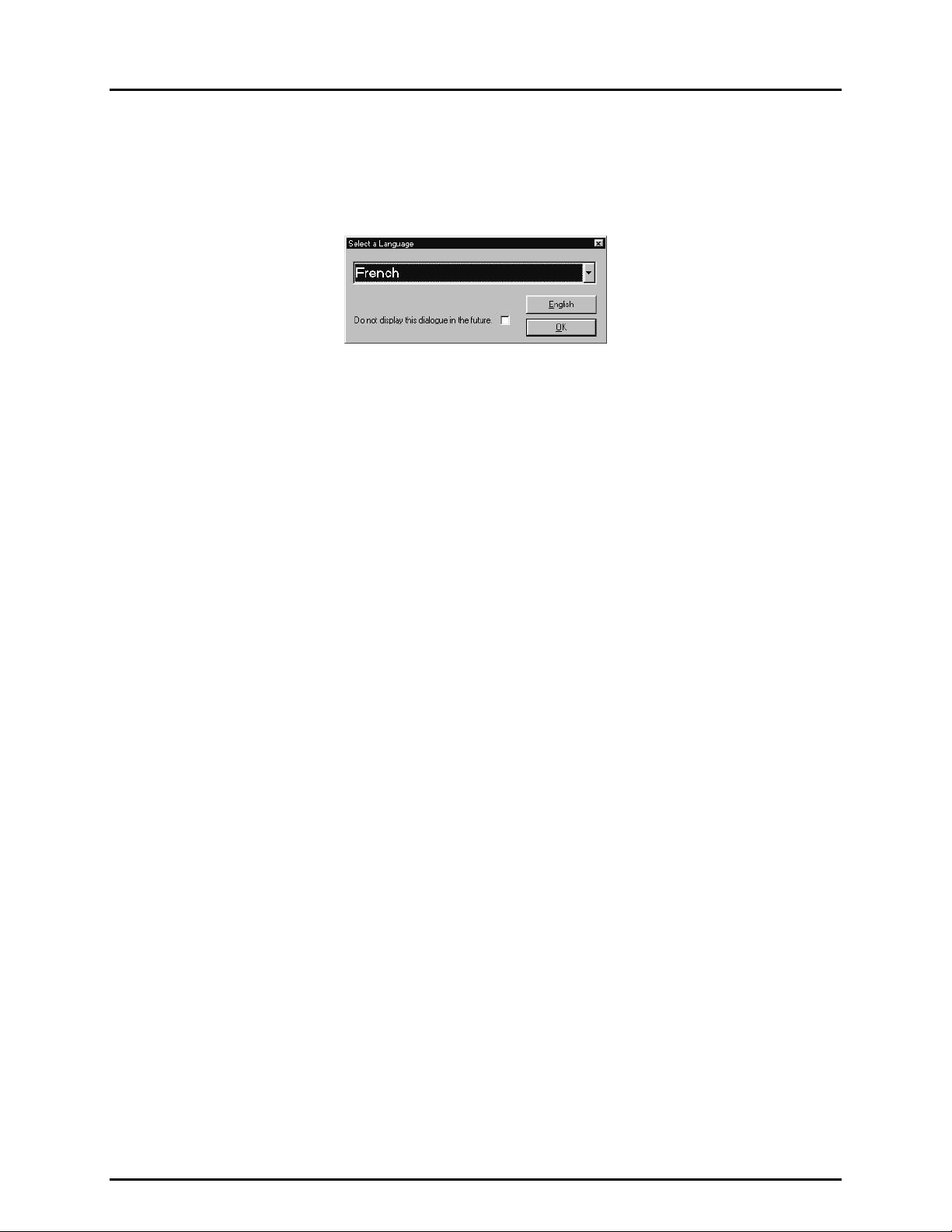
When COMPASS loads, a prompt displays requiring the selection of the language to use. Make the
selection from the lis t and press [OK]. The progr am displays all m essages and prompts in the selected
Page 3 © 1998-2000 DH Instruments, Inc.
Page 18
COMPASS® FOR PPC/RPM™ USER’S MANUAL
language. Subsequent runs of COMPASS display this dialog in the language selected in the previous run.
The [English] button will always run COMPASS in English and has the same effect as choosing
[English] from the language list. Check the <Do not display..> box at the bottom of the window to
prevent this displa y in the future. The language c an be changed while running COMPASS by selecting
[Tools], [Options], [Language] (see Section 8.3.6).
Figure 1. Language Selection
2.6 UNINSTALLING
To uninstall COMPASS, use the Remove COMPASS for PPC/RPM icon in the COMPASS program
group created during ins tallation. Alternatively, use the Ad d/Remove Programs feature in the W indows
Control Panel and select COMPASS for PPC/RPM. In both cases, a series of prompts must be followed in the
application removal program to uninstall COMPASS. All installation files and registry updates are removed.
Data directories cr eated by running COMPASS are not rem oved by uni nstalling. It is up to the user to
manually remove th ese da ta dir ect ories. T he a pplic ati on rem oval program wil l al ways dis pla y a mes sage
indicating COMPASS was not com pletely removed when executed and th e data directories ar e present.
Any file management tool such as Windows Explorer can be used to remove these data directories.
© 1998-2000 DH Instruments, Inc. Page 4
Page 19

3. OPERATING PRINCIPLES
33..
O
PPEERRAATTIINNGG
O
P
RRIINNCCIIPPLLEES
P
S
3.1 OVERVIEW
COMPASS for PPC/RPM is an application program intended to automate the test and calibration process
to the extent supported by your calibration hardware and appropriate for the DUT being calibrated.
COMPASS supports autom ated operation of DHI PPC and RPM transfer standards but can als o be used
with any type of pres sure standard from any manuf acturer. This feature allows COMPASS to be used
systematically to provide consistent data formats and report generation for all of your pressure calibrations.
COMPASS sets up and maintains files on devices under test (DUT) (see Section 6) and testing
procedures (see Sec tion 7) to assoc iate with DUTs . These files are recalled to run tests. Tests are run
using the hardware th at has been configur ed (see Section 8.2) in COM PASS. While running a tes t, data
is acquired and stored in a standard ASCII comma or tab delimited data file (see Section 12). Within
COMPASS, data files m ay be viewed (see Section 9 .2), used to generate plots (see Sec tion 9.4) and
used to generate reports (see Section 1) which can be customized with user edited templates.
COMPASS operations foll ow conventional Windows protocol for file management, menu and message
formatting, graphics and editing.
Devices under test (DUT) and test pr ocedures are def ined and recorded in *.dut and *.ts t files. To run a
test, first a *.dut f ile m ust b e create d (see Secti on 6.2) to def ine the DUT that wil l be test ed and a *.ts t file
must be created (se e Section 7.2) to pro vide COMPASS with the exac t testing procedure f or that DUT.
The hardware configurat ion, including the pressure referenc e device, the electrical measuring dev ice (if
present) and the computer ’s IEEE 488 card (if present) used to run the t est is specified with a Hardware
Configuration Tool ( see Section 8.2). Once “DUT” and “test” files have been set up, and the hardware
configuration has been defined, tests can be run (see Section 5.2).
Many operationa l preferences relating to how test are i nitialized and ru n, and how data is g athered and
stored are configurabl e with user options (see Sectio n 8.3). The use of these configura ble preferences
results in a test environment that is customizable to meet the testing needs of a diverse group of end users.
As a test runs, the data is c oll ected in a “ l og” f ile ( s ee Sect ion 12 .2) . When the test completes, the r es u lts
of the test are copied f rom the “ log” f ile in to “da ta” f iles . “Data” f iles are des igned to be eas il y exported t o
other applications by the u ser for further analysis or report ge neration. In addition, COMPASS includes
integrated analysis and reporting func tions which allo w full custom ization of repo rts (see Sec tion 1). Any
number of custom report formats can be creat ed and employed. Re ports can then be edit ed, printed or
saved. A plottin g function allows vario us auto-sc aled err or plots fo r test results t o be view ed and printed
(see Section 9.4).
Detailed inform ation and assis tance on COMPASS application a nd functions ar e available i n this manual
and with on-line help (accessed by pressing [F1] or selecting [H
elp]).
Page 5 © 1998-2000 DH Instruments, Inc.
Page 20

COMPASS® FOR PPC/RPM™ USER’S MANUAL
3.1.1 BASICS SUMMARY
In summary, the following steps and sections s hould be refer red to while trying to s et up and
run a test for the first tim e. Subseque nt tests will onl y require a sel ection of the desired DUT
and test file. The Run T est section of this manual has a m ore detailed explanation of the
requirements to run a test in COMPASS (see Section 5.2). Several COMPASS exam ples
and frequently asked ques tions are in t he Qu ick Tips section of this m anual ( see Section 1 3).
These sections are also very useful in gett in g star te d.
• Select [DUT], [Create] to create a DUT (see Section 6.2). A DUT that outputs an
electrical signal suc h as V, m V or m A will most lik ely use a dig ital m ultimeter . This DMM
should be set up in the program configuration (see Section 8.2).
• Select [Tools], [Configure Hardware] to update the program configuration
(see Section 8.2). This includes setting up the press ure reference as well as any other
peripheral devices required by a DUT. This option should be used t o set up a DMM,
multiplexer and s elect the system IEEE 488 i nterface card. Once these selec tions are
made there is no need to access the configuration unless a change in one of these
devices occurs. M ake sure the des ired selec tions are m ade on the [CONFIGURATION]
tab of the hardware configuration.
• Select [Test] , [Create Test] to create a test that will define the pr essure sequence and
other aspects of the testing procedure (see Section 7.2).
• Select [Run], [Run Test] or the corresponding toolbar shortcut to run the test.
© 1998-2000 DH Instruments, Inc. Page 6
Page 21

4. MAIN RUN SCREEN
44..
M
M
AAIINN
R
R
UUNN
S
CCRREEEEN
S
N
4.1 OVERVIEW
The main screen contains the:
• Main menu bar to access all COMPASS menus and functions (see Section 4.2).
• Run test toolbar with seven test running short cut keys (see Section 4.4).
• Run test screen providing complete real tim e information on test progress and results as a test is
running (see Section 4.3).
4.2 MAIN MENU BAR
The main menu is divi ded into seven separate selections. Each menu item is summarized below and
covered in detail in Sections 1 through 1:
[Run] Initialize and run tests. This menu also contains the choice used to exit the program
(see Section 1).
[DUT] All device under test (DUT ) inf orm ation is hand led her e b y creating, editin g and d eletin g *.dut
files (see Section 6).
[Test] All test procedure information is handled here by creating, editing and deleting *.tst files
(see Section 7).
[Tools] Access tools to c onfigure the test hard ware used by COMPASS, sel ect user preferences to
customize test ini tializati on and exec ution, select user pref erences f or file locati ons, m aintain
lists and send discreet commands to interfaced devices (see Section 8).
[Data] View, plot or print the raw data contained in the *.dat files that result from test execution
(see Section 9).
[Report] Edit report templates. Generate reports from *.dat files, save and print reports (see Section 1).
[Help] Access on-line help (see Section 1.
Page 7 © 1998-2000 DH Instruments, Inc.
Page 22
COMPASS® FOR PPC/RPM™ USER’S MANUAL
4.3 RUN TEST SCREEN
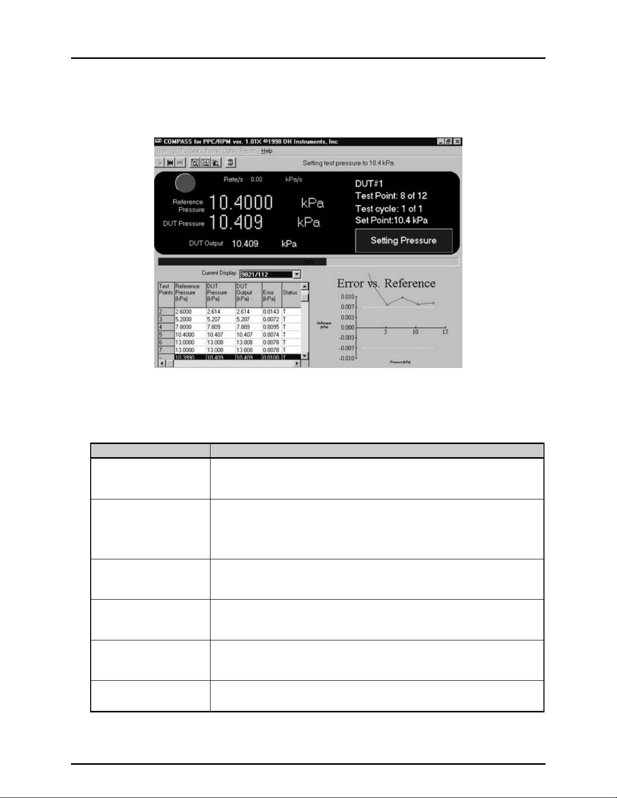
The Run Test screen provides real time information on test execution while a test is running.
Figure 2. Run Test Screen
The run test screen is segmented into eight functional areas described on Table 1.
Table 1. Run Test Screen
FEATURE DESCRIPTION
Status Message Bar
(Top line next to the
run test toolbar)
Read-out Panel
(Top left hand
quarter of screen)
Ready Indication LED
(Circle in the top left hand
corner of the screen)
Test Progress Summary
(WHITE characters in upper
right hand quarter of screen)
Current Function Box
(BLUE box in top right hand
quarter of screen)
Test Progress Bar
(Across middle of screen)
Displays real time messages describing t he sp ecific acti on COMPASS is executing. Uses
color coding and font changes to indicate that the program is running and to draw attention
when needed.
Provides real time readings of reference press ure, DUT output, DUT pressure (c alculated
from DUT output if DUT output is other than pressure), rate of change (stability) of
reference pressure and a green/red circular indicator of pressure ready/not ready (see
PPC or RPM Operation and Maintenance Manual for ready/not ready definition).
Readings are only displayed for values that can be read remotely by COMPASS from
interfaced devices. If no values are available, the fields show < -------- >.
Changes color from GREEN to RED to indicate whether the pressure reference meets or
fails the stability criterion specified in the test file.
Displays current DUT # (always one for single DUT tests), test point currently being
executed and total number of points in test, cycle # (always one for single c ycles tests),
and nominal pressure of current test point.
Indicates the current macro test function being executed by COMPASS (<IDLE>,
<Initialize Test>, <Leak Check>, <Pressure Cycle>, <Setting Pressure>, <Dwelling>,
<Taking Data>).
Visualizes test progress with a p rogressive horizontal bar and percent executed value.
Progress is in terms of current test point over total number of test points.
© 1998-2000 DH Instruments, Inc. Page 8
Page 23
4. MAIN RUN SCREEN
FEATURE DESCRIPTION
<Current Display> Selector
(Top of bottom left hand
quarter of screen)
Test Point Log
(Bottom left hand quarter of
screen)
Run Time Plot
(Bottom right hand
quarter of screen)
Identifies the DUT that is currently being displayed in the test point log and in the run time
plot. DUTs are identified by serial number/ID. If multiple DUTs are being tested, a dropdown menu to select an individual DUT or <All> is available.
Selecting <Pre Test> causes information on the leak test and/or cycling (exercising)
conducted at the beginning of the test to be displayed i f these were included in the test
definition.
The data for each test point is recorded and displayed in the test point log. If the DUT
error for the current test point exceeds the DUT tolerance, the computer beeps (if audible
feedback is enabled) and the row containing the t est point is highlighted (only the most
recent out of tolerance test point is highlighted). The status column for this point will
include a <T> for out of tolerance.
When testing multiple DUTs, selecting a single DUT in the <Current Display> selector
causes the complete test log for the DUT to be shown; selecting <All> causes the current
point for all the DUTs to be shown. The change f rom a single t o all DUTs c an be made at
any time.
<Test Point> is the number of the pressure point in the pressure point sequence.
<Reference Pressure> is the reading from the reference pressure device.
<DUT output> is the output recorded from the DUT. <DUT Pressure> is the pressure
calculated from the output using the output and pressure spans from the “DUT” file. If the
DUT output is pressure, DUT output and DUT pressure are identical.
<Error> is the difference between the DUT pressure and the ref erence pressure (DUT
pressure – reference pressure).
The <Status> column reports the status of the test point.
<OK> indicates that the test point executed normally and the DUT error was in tolerance.
<T> indicates that the DUT error was out of tolerance.
<S> indicates that data was taken from the reference when the reference was not ready
(applies only to automated reference devices).
The run time plot shows a plot of the DUT error (DUT pressure - reference pressure) in the
DUT pressure units.
The plot can scale automatically to the error data or include DUT tolerance bars and scal e
automatically to the DUT tolerance. Which scaling is used is determined by user
preference: [T
When testing multiple DUTs, selecting a single DUT in the <Current Display> selector
causes the error plot of the selected DUT only to be shown; selecting <All> causes error
plots for all the DUTs to be shown simultaneously. The change from a single to all DUTs
can be made at any time. Clicking on the plot causes a plot legend to appear.
The <Maximiz e Graph> key of the run test tool bar (see Section 4.4) may be used to
maximize the graph to the full screen. Click the key again to minimize the graph.
ools], [Options], [Run Test], <Plot data to tolerance> (see Section 8.3.3).
Page 9 © 1998-2000 DH Instruments, Inc.
Page 24
COMPASS® FOR PPC/RPM™ USER’S MANUAL
4.4 RUN TEST TOOLBAR
The run test toolbar pro vides a shortcut method for starting a t est, accessing DUT and test procedure
information while a test is running and other test func tions. The toolbar is located in the up per left-hand
corner of the main run screen. To use a tool, click on the tool icon.
Table 2 lists the tools available on the toolbar.
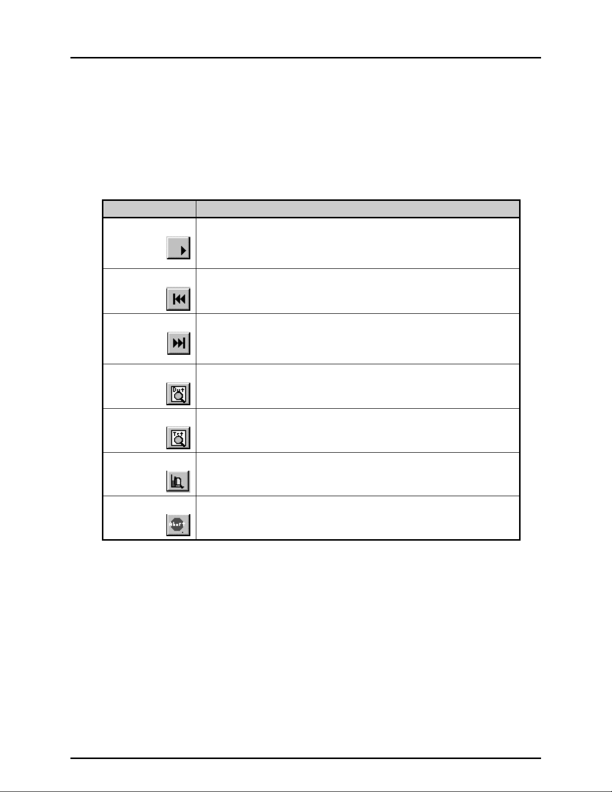
Table 2. Tools Available on the Toolbar
ICON DESCRIPTION
Starts a test, beginning with DUT selection or displays an option to re-run a test. Tests
Run
can be re-run only if the previous test was succ essfully initialized, and no configuration
changes have occurred since the com pletion of the previous run. The current DUT and
test file can be edited only. If this criterion is not met, the re-run option will not display
and test initialization immediately begins with DUT selecti on.
Step Back
Step Forward
View DUT
View Test Procedure
Maximize Graph
Causes the current test point to be interrupted and t he test point sequence to st ep back
to the most recent set pressure step. Subsequent clicks caus e the tes t to step back one
point for each click. This key is used to repeat points when needed.
Causes the current test point to be interrupted and the test point sequence to step
forward to the set pressure s tep of the next pressure point. This key enables only after
the step back key has been used; it cannot be us ed to s tep f orward over tes t point s t hat
have not been executed. Most often it is used to avoid repeating all previously execut ed
points when the step back key has been used to go back several pressure points.
Causes the DUT Profile screen to be displayed over the run test screen. This allows
complete information on the DUT being run to be reviewed without i nterrupting the t est.
Click <OK> to close the screen.
Causes the Test Definition screen to be dis played over the run tes t screen. This al lows
complete information on the current test proc edure to be reviewed without interrupting
the test. Click <OK> to close the screen.
Causes the current run time plot t o be maximized. Toggles between maximized and
standard size plots.
Abort
Causes the <Abort Test> confirmation pop-up to appear to abort the test that is running.
© 1998-2000 DH Instruments, Inc. Page 10
Page 25

5. THE [RUN] MENU
55..
T
T
HHEE
[[R
R
N
UUN
M
]] M
U
EENNU
5.1 OVERVIEW
The [Run] menu is used to execute a test and to exit COMPASS. It has the following choices:
un Test], [Re-Run Test] and [Exit].
[R
5.2 [RUN], [RUN TEST]
This menu selectio n is used to start execution of a test. Pressing the [Run] key on the r un test toolbar
has the same effect as selecting this menu option. Test execution is divided into three sequential parts:
Test Initialization Selects the DUT and test procedure to run, sets up the reference, sets up DUT
identification and communications, enters user ID. The sequential steps of test
initialization can be turned ON or OFF using [Tools], [Options], [Initialize Test]
(see Section 8.3.2).
Run Test uns leak check (if included), runs pressure cycling to exercise DUTs (if included),
runs test pressure points and takes data at each point. The test run details are
defined by the *.dat file. Certain aspects of operation can be customized using
[Tools], [Options], [Run Test] (see Section 8.3.3).
Test Conclusion Presents <Test Notes> screen to rec ord test specific notes and <T est Complete>
screen with various test conclusion options.
5.2.1 TEST INITIALIZATION
Test initialization is the first part of test execution. The seven sequential steps of test
initialization can be turned ON or OFF using [To
(see Section 8.3.2). The test initialization sequential steps are listed immediately following
below (see Sections 5.2.1.1 through 5.2.1.7 for details on each initialize test step):
Select DUT File (see Section 5.2.1.1): The DUT selection tool is presented allowin g
browsing of DUTs avai lable and selection of the DUT file to run. If this s tep is turned
OFF, the screen is not shown and the last DUT file used is automatically selected.
Preview DUT (see Section 5.2.1.2): The DUT profile screen is presented to allow
verification of the DUT file to run. If this step is turned OFF, the step is omitted entirely.
Select Test File (see Section 5.2.1.3): The select test file screen is presented
identifying the primary and secondary test files associated with the current DUT and
allowing browsing of the test f iles available. If this ste p is turned OFF , the scree n is not
shown and the primary test file associated with the DUT is automatically selected.
Preview Test (see Sect ion 5.2.1.4): The pre view test file sc reen is presented to allow
verification of the test file to run. If this step is turned OFF, the step is omitted entirely.
ols], [Options], [Initialize Test]
Page 11 © 1998-2000 DH Instrument s, Inc.
Page 26
COMPASS® FOR PPC/RPM™ USER’S MANUAL
Reference Verification/Range Selection (see Section 5.2.1.5): The reference
verification scree n is presented ident ifying the source of reference pressur es to be used
in running the test. If the reference has m ultiple ranges and ca n be communic ated with
remotely, the range selection function is included. The range recommended by
COMPASS or a d ifferent r ange can be selec ted. If this step is turned OF F, the screen is
not shown and the recommended range is automatically accepted.
Setup DUT(s) (see Section 5.2.1.6): The setup DUT(s) screen is presented.
This screen is intended to allow input of DUT identification and communication details
if necessary. If the DUT being run is a m anual data acquisition t ype DUT and the DUT
file is a DUT defini tion, t he scr een serves as verificat ion of DUT identif ication onl y. If the
DUT file is a DUT prof ile, identification of the DUT( s) must be provided. If the DUT(s)
being run is/are DMM, RS232 or IEEE 488 data acquisition type, the DUT
communications deta ils can be verified, changed and tested. If this step is turn ed OFF
and the DUT file is a DUT definition, the step is om itted entirely when all requ ired DUT
communications inf ormation is curren tly configured. T his means that a DMM is set up for
a DMM output DUT and the default R S232 or IEEE 488 comm ands have been set up to
meet the requirem ents of the current DUT (see Sectio n 8.3.3). If this step is turned OF F
and the DUT file is a DUT profile or the previous inform ation is not set up, the screen is
still presented and DUT identification(s) must be entered.
User ID Entry (see Section 5.2.1.7): The user ID entry screen is presented. T he last
user ID can be accepted, a new user ID m ay be enter ed, or a previo usly ent ered user ID
may be selected from the user ID drop-do wn list. If thi s s tep is turned OF F, the s creen is
not shown and the last user ID selected is automatically used.
Test initialization is complete, run test begins (see Section 5.2.2).
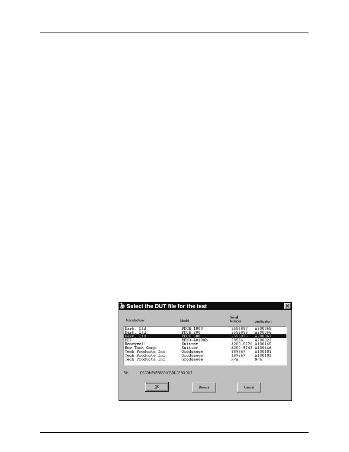
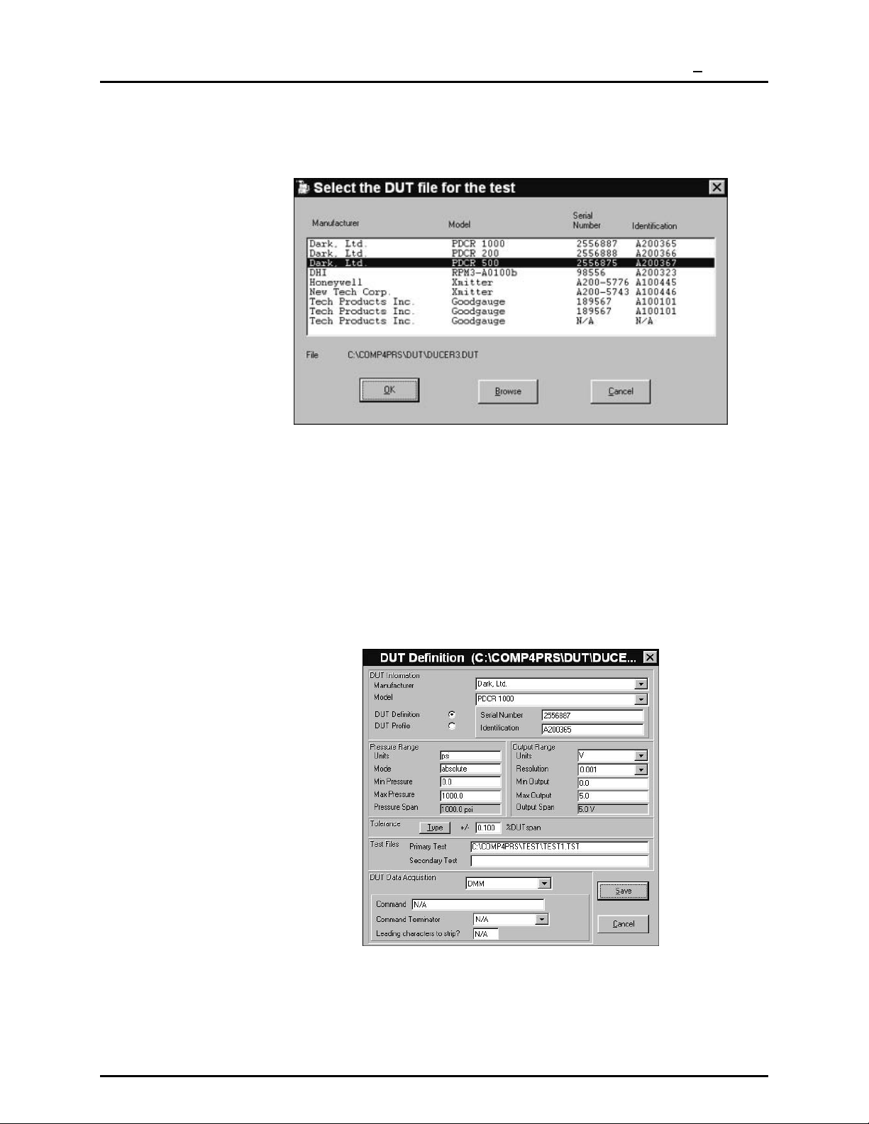
5.2.1.1 SELECT DUT FILE
The DUT selection tool is presented allowing browsing of DUTs available and
selection of the DUT file to run. If this step is turned OFF, the screen is not
shown and the last DUT file used or accessed is automatically selected.
DUTs available are listed by manufacturer, model, serial number and
identification as extracted from *.dut files. The list is alphabetical by
manufacturer. Us e your k eybo ard’s ar ro w k e ys or po in ting de vic e to hi ghl ig ht th e
desired DUT. The highlighted DUT file name and path are listed following:
Figure 3. Select the DUT file for the Test Screen
© 1998-2000 DH Instruments, Inc. Page 12
Page 27
5. THE [RUN] MENU
To select the DUT based o n its f ile nam e, or if the f ile you want was not store d in
the directory specified for DUTs in your file location preferences (see Section
8.3.5), click <Browse> to activate a standard Windows file selection pop-up.
Figure 3. Select the DUT file for the Test Screen
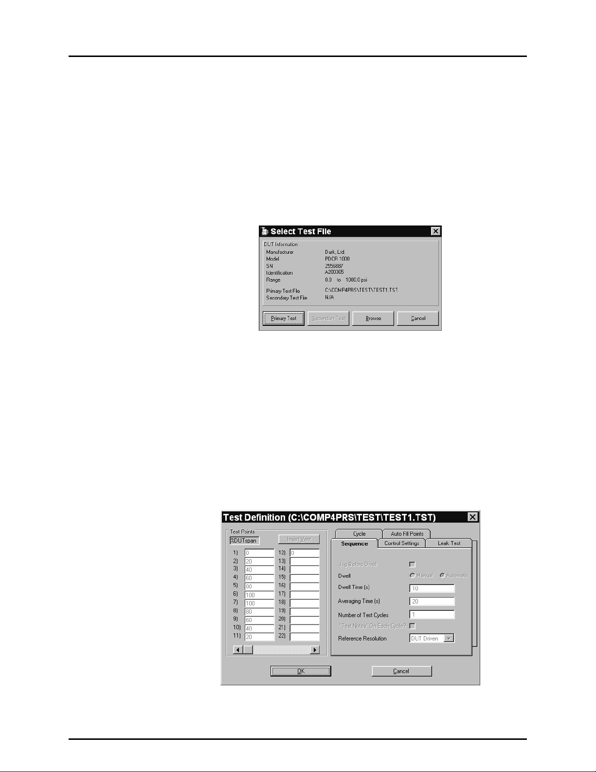
5.2.1.2 PREVIEW DUT
The DUT profile screen is presented to allow verification of the DUT file to run. If this
step is turned OFF , the ste p is sk ipped entir ely. Edits cannot be m ade to a DUT
file during test initialization.
If the previe wed D UT is cor r ect, clic k <OK> and test ini ti ali zat io n wi ll c ont in ue. If the
DUT is not correc t, click <Cancel> to return to the DUT selection tool an d make
a new DUT selection. To abor t the tes t completely, click <Cancel> from the DUT
selection tool.
Figure 4. DUT Definition (C:\COMP4PRS\DUT\DUCE …) Screen
Page 13 © 1998-2000 DH Instrument s, Inc.
Page 28
COMPASS® FOR PPC/RPM™ USER’S MANUAL
5.2.1.3 SELECT TEST FILE
The select test file s c reen i s pres ente d i dent ifying the primary and secondary test
files associated with the current DUT and allowing browsing of the test files
available. If this step is tur ned O FF , the s cr een is not s ho wn and the pr imary test
file associated with the DUT is automatically selected.
The test selection screen c ontains the core information about the s elected DUT
which may be helpful in selecting the test file to run. The DUT’s primary and
secondary test files display and one of these can be selected by clicking the
corresponding selection button. To select a test file other than the primary or
secondary test file associated with the DUT, click <Browse> to activate a
standard Windows file selectio n pop-up. Click <Cancel> to abort the test completely.
Figure 5. Select Test File Screen
5.2.1.4 PREVIEW TEST
The preview test screen is presented to allow verification of the test file to run. If this
step is turned OFF, the step is skipped entirely.
The test cannot be m odified using this po p-up, but all the charac teristics can be
viewed by clicking on the appropriate tabs.
If the previewed test is correct, click <OK> and test initialization will continue. If the
test is not correct, click <Cancel> to return to the tes t selection tool and make a
new test selection. To abort the test completely, click <Cancel> from the test
selection tool.
Figure 6. Test Definition (C:\COMP4PRS\TEST\TEST1.TST) Screen
© 1998-2000 DH Instruments, Inc. Page 14
Page 29

5. THE [RUN] MENU
5.2.1.5 REFERENCE VERIFICATION
The reference verif ication sc reen is pr esented identif ying the sour ce of r eference
pressures to be used in ru nning the test. If COMPASS can communicate with
the reference remotely and the reference has multiple ranges, the reference
range selection tool and h ead adjustment is also included . If this step is turned
OFF, the screen is not shown, the recommended range is automatically accepted
and the current head (if the reference supports head corrections) is accepted.
See the Reference Pressure Device Operations and Maintenance Manual for
details on head corrections.
The reference shown is the reference currently selected in [T
ools], [Config
Hardware], [CONFIGURATION]. To change references, abort the test and go to
ools], [Config Hardware], [CONFIGURATION] to set up and/or select a
[T
different reference (see Section 8.2.1).
If COMPASS is able to communicate remotely with the reference, the range
selection tool is disp la yed. T his too l rec omm ends the range tha t COM P ASS has
determined to be the optimum range based on the span and pressure
measurement mode of the DUT . A different range may be selec ted by clicking
on the corresponding button.
If COMPASS is able to communicate remotely with the reference and the
reference supports automated pressure head corrections the current head
correction height is displayed and m ay be edited to reflect the correc t height for
the current setup. The head correction un its and/or medium cannot be change d
using this pop-up. To change these, abort the test and m ake the changes using
the reference device’s front panel function keys then restart the test. See
Reference’s Operatio n and Mainte nance Manua l for com plete information o n the
head correction function).
Erroneous data may be logged if the reference device’s characteristics are
modified manually without restarting the test. Always restart the test if
pressure reference device changes are made using the reference device’s
front panel.
Figure 7. Reference Range Selection Screen
Page 15 © 1998-2000 DH Instrument s, Inc.
Page 30
COMPASS® FOR PPC/RPM™ USER’S MANUAL
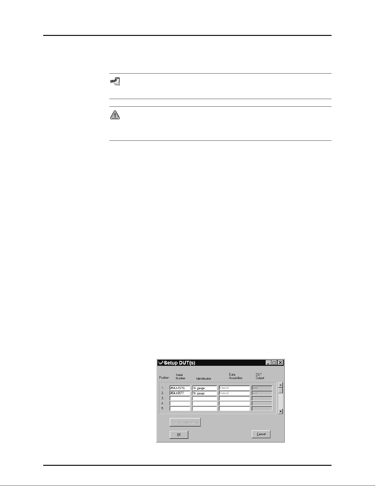
5.2.1.6 SETUP DUT(S)
The setup DUT( s) screen is pr esented. T his screen is intended to a llow input of
DUT identification and communication details if necessary.
See Section 6.2 for information on DUT profiles vs. definition files and DUT
data acquisition type.
Do not use the following characters in the serial number or identification
fields: \,/, :, *, ?, “, <,>, |, a comma or tab character. These characters will cause
problems when importing the “data” file or creating the “data” file directory.
The setup DUT(s) screen’s appearance and operation vary depending on
whether the DUT file being run is a DUT definition or a DUT profile and on th e
DUT’s data acquisition type (see Section 6.2):
• If the DUT file is a DUT definition file and the DUT data acquisition type is
manual, the screen sets up for a single DUT. The screen serves only for DUT
verification as the DUT ide ntification comes from the *.dut file and there are
no communications to verify. If the setup DUT step is turned OFF, setup
DUT is omitted entirely.
• If the DUT file is a DUT definition file and the DUT data acquisition type
is DMM, RS232 or IEEE 488, the screen sets up for a single DUT.
DUT communication details c an be verif ie d, c han ged a nd tested. If the setup
DUT step is turned OFF, s etup DUT is omitted ent irely. This f eature can be
removed only when a DUT definition is used with DMM data acquisition or the
default interface parameters (see Section 8.3.3) will work with the current DUT.
• If the DUT fi le is a DUT p rofil e file , the scr een se ts f or entr y of up to 5 0 DUTs .
The screen requires entry of a DUT serial number for each DUT to be t es ted.
Serial number entr y in the DUT position is the means b y which COMPASS
determines how many DUTs to include in the test run and the position of
the DUTs. Identification is not a requ ired field. If the DUT data acquisiti on
type is DMM, RS232 or IEEE 48 8, DUT comm unication det ails for each DUT
individually can be verified, changed and tested. If the setup DUT step is
turned OFF, the setup DUT sc reen will still ap pear and r equire serial num ber
entry to identify the DUTs to be tested.
To check communications with the DUT(s), click the <Communications
Test> button. COMPASS attempts to comm unicate with all DUTs that have
had a serial number entered using the command specified in the DUT file
and the current comm unications settings. If communication is successful, the
DUT output is update d in the <D UT O utp ut> column. If communication fails,
an error message is displayed.
Figure 8. Setup DUT(s) Screen
© 1998-2000 DH Instruments, Inc. Page 16
Page 31

5. THE [RUN] MENU
Setup DUT(s) - Data Acquisition
When using the <Setup DUTs> screen, keep in mind that DUT Data
Acquisition type refers to the manner in which data will be gathered from the
DUT. DUTs with electrical outputs are read with a DMM and the data
acquisition type is DMM (it is not the interface on the DMM such as RS232
or IEEE 488). Only DUTs read directly by RS232 or IEEE 488 interfaces are
considered to use RS232 or IEEE data acquisition.
The data acquisition colum n of the DUT Setup table (third column from the lef t)
varies depending on the DUT data acquisition type.
The data acquisition t ype can be m anual, DMM, DMM + MUX, RS232, I EEE 488
(see Section 6.2):
• If the DUT data acquisition type is manual, the data acquis ition colum n is
labeled <Data Acquisit ion> an d <Manual> is listed for the DUTs . When the
test is run, DUT readings will be entered manually.
• If the DUT data acquisition type is RS232 or IEEE 488, the data
acquisition column is labeled <RS232 Settings> or <IEEE 488 Address>.
When a test is run, COMPASS will r ead the DUT(s) directly using R S232 or
IEEE 488 and the command strings defined in the *.dut file. The default
RS232 DUT set tings or IE EE 48 8 addr ess are ente red f or e ach DUT . T he DUT
RS232 settings or I EEE 488 address can be changed by d ouble clicking on
the corresponding c olumn entry to access the sett ings pop-up. The def ault
RS232 parameters and IEEE 488 address for DUT communications can be
changed using [T
ools], [Options], [Run Test]. <Default DUT
Communications> (see Section 8.3.3). If RS232 is the DUT data
acquisition type, a <Chained DUTs> check box appears above the data
acquisition column. Checking the box forces RS232 settings for multiple
DUTs to be the same for all the DUTs.
• If the DUT data acquisition type is DMM, the data acquisition column is
labeled <Data Acquisition > and <DMM> is listed f or all the DUT s. When a
test is run, DUT readings will be read automatically from the DMM. The actual
DMM communications are defined and changed, if desired, in the DMM
configuration (see Section 8.2.3).
• If the DUT data acquisition type is DMM and a multiplexer is included in
the hardware configuration, the data acquisition co lumn is labeled <Data
Acquisition> and <DMM + M ultiplexer> is listed f or all the DUTs. When a
test is run, the multiplexer will automaticall y switch DUT outputs to the DMM
and DUT readings will be read automatically from the DMM. The actual
DMM and multiplexer com munications are defined and changed, if desired,
in the DMM and multiplexer configuration (see Sections 8.2.3 and 8.2.4).
For DUT profiles with RS232 or IEEE 488 data acquisition type, the position
in the communication setup corresponds to the DUT number in the DUT
command list of the DUT profile (see Section 6.2) (i.e., COMPASS will use the
command assigned to DUT 3 in the DUT profile to communicate with
Position 3 of the communications setup, even if there is no entry in
Positions 1 and 2). When setting up DUT communications, for DUT profiles
with DMM data acquisition type using a multiplexer to switch DUTs, the position
in the communication setup corresponds to the multiplexer command
number from the multiplexer definition (see Section 8.2.4) (i.e., COMPASS will
use multiplexer switching Command 3, followed by the DMM command, to read
Page 17 © 1998-2000 DH Instrument s, Inc.
Page 32

COMPASS® FOR PPC/RPM™ USER’S MANUAL
Position 3 of the communications setup, even if there is no entry in
Positions 1 and 2).
5.2.1.7 USER ID
The user ID entry screen is presented. T he last user ID can be ac cepted, a ne w
user ID may be entered, o r a previously entered user ID m ay be selected from
the user ID drop down l ist. If this step is turned OFF , the screen is not shown
and the last user ID selected is automatically used.
Any time a new user ID is entered, it is automaticall y added to the user ID list.
Names can be removed from the list using [To
(see Section 8.3.1).
5.2.2 RUN TEST
After test initialization is complete, run test begins.
The test procedure is defined by the *.tst file (see Section 7.2) associated with the DUT
being tested. Prior to running a test, various aspects of run test behavior may be
customized (see Section 8.3.1).
ols], [Options], [Maintain Lists]
During run test the main menu bar is disabled but th e run test toolbar is ac tive. Use the run
test toolbar keys to vie w de tai led D UT or test information whil e the t es t is r unn in g, to s tep tes t
points back or forward, to maximize the run time graph or to abort the test (see Section 4.4).
A test that is running can be abort ed at any time by pressing the computer ’s [ESC] key or
clicking on the <Abort Test> button of the run test tool bar. Before aborting the test,
COMPASS requires confirm ation and quer ies whethe r the partia l data f ile conta inin g the data
collected for the test so far should be saved.
The run test sequence is as follows:
Run leak test: If a leak test is specified in the test procedure (*. tst file), the leak test
is run. Pressure is set to the leak test pressure. The leak test time counts down.
Pressure is vented. If pressure setting is manual, the user is prompted to set
the pressure. If reference reading is manual, th e user is prom pted to enter the ref erence
reading at the start and f ini sh of the leak test c ountdo wn. The l eak rate is c alcu lated and
leak test pass/f ail determ ined. Leak test res ults are posted in the first line of the test point
log by selecting <Pre Test> in the <Current Display> selector. If the le ak test f ails due to
a l ea k test se t pre ssure time-out o r l eak rate lim it exceeded and <Continue on failure> is set
to <No> in the *.tst file, the test aborts. If <Continue on failure> for leak test is set to <Yes>
test execution continues.
Run cycle(s) (exercise DUTs): If run cycles are specified in the test file, exercising
occurs now. Pressure is set to the cycle min pressure followed by the cycle max
pressure for the num ber of times spec ified in the test f ile. If pressure setti ng is manual,
the user is prompted to s et the pres sure. T he res ults of the c ycling tes t are pos ted i n the
first line of the test point lo g by selecting <P re Test> in the <Curren t Display> selector.
If cycling fails due to a cycle s et pressure time-out and <Continue on failure> for cycling is
set to <No> in the *.tst file, t he t est a bor ts. If <Continue on failure> is set to <Yes>, test
execution contin ue s.
© 1998-2000 DH Instruments, Inc. Page 18
Page 33

5. THE [RUN] MENU
Set pressure test point: The test pressure point is set. How the pressure is set is
determined by the *.ts t file. If pressur e setting is manual, the user is prom pted to set t he
pressure to the pressur e point value. If pressure setting is aut omated, pressure is set
automatically using either dynamic or static control as specified in the *.tst file.
Once <ENTER> has been pressed in manual c ontrol, test exec ution continues. Once a
pressure ready cond ition has been reached or a se t pressure time-out has occurr ed in
automated control, tes t exe cution co ntinues. Se e the Pres sure Ref erence O perat ion and
Maintenance Manual for information on static and dynamic control and ready/not
ready conditions. In automated control, if set test pressure times out, the audible
feedback failure sound will be made if the feature is enabled and TIMEOUT will be
logged in the data file for the set pressure time. The <Status> column will not
necessarily display <S> under these conditions. This displ a y is res er ved for the occasion
that the actual DUT data is taken when the reference pressure is unstable.
Dwell: If automatic dwell is specif ied in the *.tst file, the dwell time counts down and
execution continues. If the test file specifies manual dwell, COMPASS waits for the
operator to press <ENTER> before test execution can continue.
Read reference and DUT outputs: The reference and the DUT(s) are read as many
times as possible for the averaging period. Averaging occurs only for references and
DUTs that can be read automatically. In the event tha t the c ur rent tes t p oi nt is 0 abs ol ute
or any static pressure, t he reference pressure will ne ver be averaged if the DUT outpu t
is manual. This special case preven ts averagi ng a refer ence pressur e that could c hange
significantly over t he duration of the av eraging time. Com paring this averaged p ressure
to a non-averaged DUT pressure will yield inconsistent data (see Section 5.2.2.1 for
manual data entry). When running multiple DUTs, a common manual reference entry
can be applied to a ll the D UTs by setting a preferenc e in [T
ools], [Options], [Run Test]
(see Section 8.3.3). Af ter reading the reference and the DUT (s), if there are more test
points in the test, test ex ecution continues with the next test point ( go to Step 3). If this
was the last test point of the last test cycle, run test is complete and test conclusion
begins (see Section 5.2.3).
5.2.2.1 MANUAL ENTRY DATA ACQUISITION
When <Manual> is selecte d as the DUT data acquis ition or t he reference device
in a test cannot be read rem otely, the <Manual entry> screen displa ys. Enter
the required output of the DUT and/or reference pressure as required. All DUT
entries must be in the output units setup in the “DUT” file and the reference
pressure must be entered in the pressure units of the DUT. Use a COMPASS
preference under [Tools], [Options], [Run Test] to allow only one manual
reference pr essure to be en tered (see S ect ion 8. 3. 3). To retak e a referenc e point,
use the <Run Test Toolbar> back option (see Section 4.4). Each entry field displays
according to the DUT position set up during test initia lization (see Secti on 5.2.1.6).
Press [Enter] to move to the nex t require d f i e ld after an entry is mad e. To close t h e
manual pressure entry screen, press [ENTER] on the last entry field or click <OK>.
Figure 9. Manual Pressure Entry
Page 19 © 1998-2000 DH Instrument s, Inc.
Page 34

COMPASS® FOR PPC/RPM™ USER’S MANUAL
5.2.3 TEST CONCLUSION
After run test is complete, test conclusion begins. Test conclusion has two steps.
Test Notes: The <Test Notes> pop-up appears to allow the user to enter notes
concerning the tes t run that has j ust completed. The notes ar e included in the raw data
file and can be used in reports . In a multi-cycle test, s eparate notes can be incl uded for
each test cycles data file or only the last data file as specified by user preference
(see Section 7.2.6).
Test Comp lete Screen: The <Test Complete> s creen gives the name and path of all
data files created d uring the test and offers various post test options. Operat ion always
returns to the <Test Complete> screen until <Exit Test> has been selected.
Figure 10. Test Complete Screen
The multiple “data” file selection in the <Test Complete Screen> is designed to allow
multiple reports to be generated in one step using the <Generate Report> feature.
Use one “data” file selection when accessing any option except <Generate Report>. If
multiple files are selected, only the file name that currently has the focus is used. In
most cases, this is the first selected “data” file.
Table 3 lists the test complete options.
Table 3. <Test Complete> Screen Options
FEATURE DESCRIPTION
<Rename>
<View Test Data>
<Generate Report>
<Rerun Test>
<Plot Test Data>
<Exit Test>
Used to override the default file name and directory for the data file resul ting from the
test. Brings up a standard Windows Save As file box showing the default di rectory
and file name. These can be rewritten, if desired.
Used to review raw test data immediately f ollowing test completion without exiti ng the
test completely. The data fil e viewer appears with the *.dat fil e from the test that has
just completed open. This is funct ionally equi valent to selectin g [D
with the data file from the test that has just completed (see Section 9.2).
Used as a shortcut to generat e a test report immediately following test completion.
Multiple data files can be selected to generate multiple reports in one step. The
COMPASS Report Editor merges each selected data file with the last used report
template to generate a separate report for each data file (see Sect ion 1). The report
editor then displays each report generated. This is functionally equivalent to running
the COMPASS Report Editor as a standalone application and selecting the [File],
[Generate Report] option (see Section 10.4.2).
Used to rerun the same DUT(s). The result is functionally equi valent t o exiting the t est
and selecting [R
Used as a shortcut to immediately view plots using the data from the test that just
completed. This choice is functionally equivalent to exiting the test and selecting
[D
ata], [Plot Test Data] (see Section 9.3).
Exits the test. The <Test Complete> po p-u p dis ap pe ars a nd t he m ai n menu and associ at ed
screen reappear. The current test data remains active until another test is started.
un], [Re-Run Test].
ata], [View Test Data]
© 1998-2000 DH Instruments, Inc. Page 20
Page 35

5. THE [RUN] MENU
5.3 [RUN], [RE-RUN TEST]
[Re-Run Test] is provid ed t o r es tart a tes t that was ab or ted pr ior to c ompletion for setup specif ic reas ons ,
for example when a test was started without a pr essure suppl y. If the test is abo rted [Re-Run T est] can
be used to skip the tes t initiali zation s teps. Tes ts can be re-run onl y if the pr evious test was suc cessf ully
initialized, and no [CONFIGURATION] selections have occur red s inc e the completion of the prev io us run.
The DUT and test file used in the m os t r ec ent test c an be edited o nl y. New DUT and test f iles m a y not be
selected. If this criterion is not met, the re-run option does not display. Use [Run Test] to start test
initialization with DUT selection.
5.4 [RUN], [EXIT]
This selection caus es the COMPASS program to ter minate if a test is not runnin g. If a test is running,
[Exit] acts like <Abort>. It must be selected a second tim e after the test closes before the option will
close COMPASS. This operating princip le also applies when using the contro l box X found on the t op
right corner of the COMPASS main window.
Page 21 © 1998-2000 DH Instrument s, Inc.
Page 36

COMPASS® FOR PPC/RPM™ USER’S MANUAL
N
N
OOTTEES
S
© 1998-2000 DH Instruments, Inc. Page 22
Page 37
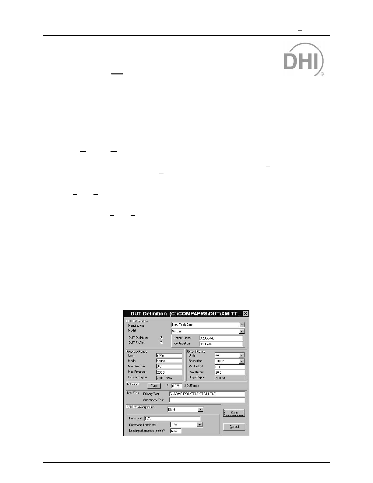
6. THE [DUT] MENU
66..
T
T
HHEE
[[DDUUTT]] M
M
U
EENNU
6.1 OVERVIEW
The DUT Menu accesses the functions used to set up and maintain *.dut files. *.dut files define the
devices under test (DUTs) that are tested using COMPASS.
6.2 [DUT], [CREATE DUT]
The *.dut file defines all th e c har acter istic s of a DUT to be tested by COMPASS. [Create DUT] is used to
create a new *.dut f ile from s cratch. Use [E
file from an old one (see Section 6.3).
Selecting [D
information blank or in its default s tate. Data enter ed on this f orm does not b ecom e active until the *.d ut
file is saved. Cl icking <Save> caus es a traditional Windows Sav e As tool to appear set to the default
*.dut file path. Select [To
Section 8.3.5). Long file nam es are supported by COMPASS to provide the ability to cr eate explicit files
names that describe the DUT file.
There are two types of *.dut files:
UT], [Create DUT] causes the <DUT Definition/Profile> screen to appear with all the DUT
ols], [Options], [File Locations] to change the defau lt file path if desired ( see
dit DUT] to change an ex isting * .dut f ile or m ake a ne w *.dut
DUT definition files define specific individual DUTs and include serial number and
identification fields. Definition file DUTs can only be tested one at time.
DUT profile files define a general DUT type and do not include serial number and
identification fields. DUT prof iles are used to run m ultiple DUT tests. T he DUTs
are identified during test initialization.
Both DUT definitions and profiles are created using the <DUT Definition/Profile> screen.
Figure 11. DUT Definition (C:\COMP4PRS\DUT\XMITT …) Screen
Page 23 © 1998-2000 DH Instrument s, Inc.
Page 38

COMPASS® FOR PPC/RPM™ USER’S MANUAL
The purpose of the <DUT Definition/Profile> fields a nd settings as well as instructions on ho w to use
them are provided in Table 4.
Table 4. <DUT Definition/Profile> Screen
FEATURE DESCRIPTION
DUT Definition /
Profile
(radio button
selection)
Manufacturer
(required entry
Model
(required entry
Serial Number
(required entry
field, DUT
definitions only)
Pressure Units
(required
selection field)
Determines whether the *.dut file created will be a DUT definition or a DUT profile. One must be
selected. Default is DUT definition. Use a DUT definiti on if t his *.dut f ile is f or a specific, unique DUT
that will be tested individually. Use a DUT profile if this *.dut file will be used to test multiple DUTs
simultaneously.
The manufacturer can be selected from the drop-down list or a new manufacturer can be entered
manually. Manual ly ent ere d manuf acture rs a re autom atic ally ad ded to the d rop-do wn list (alp habetic all y).
Select [T
field)
DUT files that contain a deleted manufacturer name are still valid.
The model number or name for the DUT can be sel ec ted from the drop-down list or a new model can
be entered manually. Manually entered models are automatically added to the drop-down list (alphabetically).
Select [T
field)
DUT files that contain a deleted model are still valid.
Write in the DUT serial number. The default data file naming preference will store the “data” files
created when tests are run in a directory named using the value entered in t his field (see Sections
12.3 and 0). DUT profiles do not include a serial number during the creation of the DUT.
Write a device identification, if desired. This field can be used for internal tracking of DUTs or to
record other information. Any c ombinati on of inf ormation c an be entered i nto t he ID fi eld. The val ue
entered will be included in the run test data files and c an be included in repo rts . DUT prof iles do not
include a device ID. A COMPASS preference can be set the device identification field as the
directory name for the DUT “data” files instead of the serial number field (see Sections 12.3 and 0).
ools], [Options], [Maintain Lists] to delete unwanted manufacturers (see Section 8. 3.1).
ools], [Options], [Maintai n Lists] to delete unwanted model s from the lis t (see Section 8.3. 1).
Do not use the following characters in the serial number or identification fields: \,/, :, *, ?, “, <,>, |, a
comma or tab character. These characters will cause problems when importing the “data” file or
creating the “data” file directory.
Figure 12. Unit/Mode Selection
Pressure units in which the pressure i nput range of the DUT is expressed. Clicking on this field
causes the <Unit/Mode Selection> pop-up to appear. Click the [Pressure Units] tab and select a
pressure unit from the drop-down list. The conversion factor to Pascal will display as each new unit
is selected. User defined units can be created by selecting the <User Defined> item in the list and
manually entering the conversion factor to Pascal and a four character unit label in the <User
Defined> field. The conversion factor entered multiplied by the current pressure should be the
equivalent pressure expressed in Pascal. When a test is run, COMPASS displays user defi ned units
as the four character unit l abel entered. The pres sure m easurement mode (gauge or absol ute) may
also be changed at this time if desired by clicking on the [Mode] tab.
© 1998-2000 DH Instruments, Inc. Page 24
Page 39

6. THE [DUT] MENU
FEATURE DESCRIPTION
Pressure Mode
(selection field)
Max Pressure
(required entry
Input Span
(calculated field)
Output Units
(required selection
Min Output
(required entry
Pressure measurement mode (gauge or absolute) of the DUT. Clicking on this field causes the
<Unit/Mode Selection> pop-up to appear. Click the [Mode] tab and s elect <Absolute Mode> or
<Gauge Mode> by clicking the corresponding radio button. If the DUT measurement mode is
differential, select gauge. Pressure meas urement units may als o be changed at this time if desired
by clicking on the [Pressure Units] tab.
Generally, if a DUT reads atmospheric pressure when vented, it is an absolute DUT. If the DUT reads
near zero when vented, it is a gauge DUT.
Enter the lowest pressure of the DUT input range in t he pres sure units and mode specified above. In
the case of negative gauge DUTs, the <Min Pressure> can have a numericall y absolute pressure
value that is larger than the <Max Pressure> value entered. For example, many users will enter <0>
(zero) for the <Min Pressure> for a 0 (zero) to -30 inWa DUT. It is up to the user to decide which
pressure to designate “min” and which press ure to designate “m ax”. Just make sure t he DUT <Min
Output> value (see below) corresponds the <Min Pressure> entered.
Enter the highest pressure of t he DUT input range in the pressure unit s and mode specified above.
In the case of negative gauge DUTs , the <Max Pressure> can have a numerically absol ute pres sure
value that is less than t he <Min Pressure> value. For example, many users will enter <-30> for the
field)
<Max Pressure> for a 0 (zero) to –30 inWa DUT. It is up to the user to decide which pres sure to call
“max” and which pressure to call “min”. Just make sure the <Max Output> value (see below)
corresponds to the <Max Pressure> entered.
The DUT input pressure span is calculated automatically f rom the minimum and maxim um pressures
entered above. Span is the distance from the minimum pressure to the maximum press ure. When
the minimum pressure is zero, span is the same as what is often called full scale.
Units in which the DUT output is express ed. This can be a pressure or electrical unit. The DUT
output unit defaults to the i nput pressure unit when the input pressure unit is entered. If the DUT
output is pressure units, t he output span must be the same as the input span so the mi nimum and
list)
maximum output and span are copied from the input values and cannot be changed. If the DUT
output is electrical, use the drop-down list to select <V>, <mV> or <mA>.
Enter the lowest output (output c orresponding to t he <Mi n Pressure>) of t he DUT in t he output units
specified immediately above. If the output units are pressure units, the <Min Pressure> value is
copied here and cannot be changed.
field)
Max Output
(required entry
field)
Output Span
(calculated field)
Output
Resolution
(drop-down
selection list)
Tolerance Type
(selection button)
The values entered in the output fields should be output by the DUT when the corresponding input
pressure for the DUT is reached. Failure to enter the “min” and “max” pressure and output values
correctly will cause incorrect pressure calculations in COMPASS and improper test pressure sequencing.
Enter the highest output (output corres ponding to the <Max Pressure>) of the DUT in the output
units specified above. If t he output units are pressure units, the <Max Pressure> value i s copied
here and cannot be changed.
The DUT output span is calculated automaticall y from the minimum and maximum output values
entered above. Span is the distance from the minimum output to the maximum output. If the out put
units are pressure units, the <Pressure Span> value is copied here and cannot be changed.
Sets the resolution with which DUT data will be logged and displayed. Select the desired resolution
from the drop-down list. This option should be used to adjust the resolution to a level that is
appropriate for the performance of the DUT. Generally, resolution is set to one order of magnitude
greater than the DUT tolerance.
Selects the formula used to calculate DUT t olerance. The DUT tolerance t ype along with the value
entered in the tolerance field(s) is used when a test is run to calculate whether the DUT error at each
point is in tolerance or out of tolerance (see Sect ion 15.4). DUT t olerance is als o used to det ermine
the tolerance bars on test data plots. Clic king on the button caus es the a tolerance type list to dropdown. Choices are:
%DUTspan: DUT tolerance is calculat ed as the pressure span of the DUT times the tolerance
value.
%DUTreading: DUT tolerance is calculat ed as the current reading of the DUT tim es the tolerance
value.
%DUTspan or %DUTreading (greater of): DUT tolerance is calculated at each point as both
%DUTspan and %DUTreading. Tolerance used is the greater of the two.
%DUT span + %DUTreading: DUT tolerance is calculated at each poi nt as both %DUTspan and
%DUTreading. Tolerance used is the sum of the two.
Page 25 © 1998-2000 DH Instrument s, Inc.
Page 40

COMPASS® FOR PPC/RPM™ USER’S MANUAL
FEATURE DESCRIPTION
Tolerance Value
(required entry
Primary Test
(optional entry
Secondary Test
(optional selection
DUT Data
Acquisition
(DAQ)
Command
(required entry
field, RS232 or
IEEE 488 data
acquisition type
DUTs only)
Command
Terminator
(drop-down
selection list for
RS232 or
IEEE 488 only)
Leading
characters to
(required selection
field for RS232 or
IEEE 488 data
acquisition type
DUTs only)
Specifies the value in % to use in calculating the DUT tolerance. If the DUT tolerance type is
%DUTspan or %DUTreading, there is only one entry fi el d. If the DUT tolerance type is (%DUTspan
or %DUTreading) or (%DUTspan + %DUT reading), there are two entry fields.
field)
Specifies the *.tst file that is most commonly used to run this DUT. When a DUT to run is s elected,
the primary *.tst file is automatically offered as the default test (though a different file can be
selected). If *.tst file selection in test initialization is turned OFF, the primary test file will
field)
automatically be used. The associat ion of a primary test file with t he *.dut file makes it poss ible to
assure that a DUT will always be tested us ing a cons istent test procedure. The f ile is s elect ed using
a traditional Windows file browser which is activated by clicking on the <Primary Test> field. The browser
defaults to the *.tst directory. The default *.tst directory can be changed by selecting [To
[O
ptions], [File Locations] (see Section 8.3.5). Right click this field to remove the test file entry.
Specifies an alternate *.tst file for this *.dut file. When initializing a test, during *.tst file selection, the
secondary test file is automatically of fered as a selec tion choice. Operation of the sec ondary *.tst f ield
is the same as operation of the primary *.tst field. Right click this field to remove the test fil e entry.
field)
Defines the data acquisition mode of the DUT. Regardless of the selection, DUT data
must be obtained in the output units selected in the current DUT file. The selections
available are:
Manual: DUT data must be entered manually by the user during the test. No command
DMM: DUT data is obtained using the DMM setup in the hardware configuration (see Section 8.2.1).
RS232: DUT data is gathered using an RS232 interface by sendi ng the <Command> entry to
IEEE 488: DUT data is gathered using the IEEE 488 interface provided by the IEEE 488 card
Defines the string of characters which, when sent to the DUT will cause it to respond with its output in
the units specified for output units. For DUT profiles, with RS 232 or IEEE 488 data acquisiti on, up to
50 unique commands can be defined as required by the DUT. If the DUT uses the same command
for all DUT’s regardless of position, only enter the first command. COMPASS will automatically copy
this command to all remaining command fields. For DUT definitions, only one command string can
be defined. Each command entered corresponds to a separate DUT position (see Section 5.2.1.5).
Defines how the DUT terminates the command strings. The selections avail able from the drop-down
list are carriage return <CR> and carriage return + line feed <CR> + <LF>. The majority of
instruments that support an RS232 or IEE E 488 interface use carriage return and line feed as the
command terminator. Refer to the instrument documentation for more details.
Specifies leading characters to strip f rom the DUT return string in case the DUT return st ring does
not start with the output value. This allows COMPASS to properly interpret the output of devices with
different communication protocols. This field can include any combination of delimiters and
strip
numerical space values. For example, a devic e might ret urn the st ring, “Press ure: 14. 343 PSI”. The
actual output value for this example appears at positi on 11. Therefore, ten l eading characters need
to be stripped prior to processing the string. Alternatively, if the colon following “Pressure” will always
appear prior to the pressure value, “:” could be entered as the leading character t o strip. In some
cases both a delimiter and a number of characters to strip may be required. For exam pl e, if a remote
device returns <Range 1, 4.34 volts, NR 14.343 psi >. In t his example, the num ber of charac ters in
the volts output can change making it impossible to use a fixed length value for the number of spaces
to remove to access the pressure value. To avoi d this problem enter the text <,,4> as the leading
characters to strip value. This tells COMPASS to move to the second comma, then increment four
spaces to read the pressure output value. A separate value for this field can be used for every
command in the DUT.
information is required.
The output units must be: V, mV or mA when this selection is used. No command
information is required.
the DUT. The RS232 settings are not selected in the DUT file, this s election is made
during test initialization (s ee Section 5.2.1.5) prior t o running a tes t. Up to 50 individual
or common commands can be entered in the <Command> field. At least 1 command
must be entered.
selection in the hardware configurat ion (see Section 8.2.1). The IEEE 488 address is
not part of the DUT file, this entry is made during test initialization (see Section 5.2.1. 5)
prior to running a test. Up to 50 individual or comm on commands can be entered in the
<Command> field. At least 1 command must be entered.
ols],
Only non-numeric text can be used as a delimiter in the leading characters to strip field. All numerical
entries are assumed to represent the correspond numerical value.
© 1998-2000 DH Instruments, Inc. Page 26
Page 41

6. THE [DUT] MENU
6.3 [DUT], [EDIT DUT FILE]
[Edit DUT File] is used to modify an exist ing *.dut file. Use [Edit DUT File] to change an exis ting *.dut
file or make a new *.dut file from an old one (see Section 6.3).
Selecting [D
allow easy ident ification an d selection of the DUT file to ed it. The DUT file select ed becomes the ac tive
DUT and the <DUT Definition/Profile> screen is op e ned a nd loa de d with th e i nf or mation for the selected
DUT. Operat ion of this f orm and its fields an d selecti ons are th e same as when using [D
(see Section 6.2). W hen done editin g the form, save the f ile to the sam e file name to s ave changes the
DUT file or save the file under a new file name to create a new “DUT” file.
UT], [Edit DUT file], causes the DUT selection tool ( see Section 5.2.1.1) to be presented to
UT], [Create DUT]
6.4 [DUT], [REMOVE DUT FILE]
This selection is used to delete unwanted *.dut files from the hard disk.
Selecting [D
allow easy identific ation and selection of the “DUT ” file to remove. Select th e file by double clicking on
the DUT or using <Browse> to find a DUT file not in the def ault *.dut direc tor y. Once the file is selec ted,
confirmation is requ ired before the file is actually deleted. Any file m anagement tool supported by the
operating system can also be used to remove DUT files.
UT], [Remove DUT file], c auses the DUT selection tool (s ee Sectio n 6.3) to be presente d to
Page 27 © 1998-2000 DH Instrument s, Inc.
Page 42

COMPASS® FOR PPC/RPM™ USER’S MANUAL
N
N
OOTTEES
S
© 1998-2000 DH Instruments, Inc. Page 28
Page 43

7. THE [TEST] MENU
77..
T
T
HHEE
T
[[T
T
EESST
M
]] M
U
EENNU
7.1 OVERVIEW
The Test Menu acces ses the functions used to set up an d maintain *.tst files. *.tst f iles define the test
procedures used by COMPASS to test DUTs in the run test portion of test execution (see Section 5.2.2).
7.2 [TEST], [CREATE TEST]
The *.tst file defines the test procedure that is used when COMPASS runs a test on a DUT.
reate Test] is used to create a n ew *.tst file from scratch. Use [Edit Test] to change an existing *. tst
[C
file or make a new *.tst file from an old one (see Section 7.3).
Selecting [T
information blank or in its default state. Data entered on this f orm does not becom e active until the *.tst
file is saved. Clicking <Save> caus es a tra ditional Windows Sa ve As too l to a ppe ar set to the d efault *.tst
file path. Use [To
est], [Create Test], causes the <Test Definition> screen to appear with all the test
ols], [Options ], [Fi le Loca tions ] to change the default file path i f desi red (see Se ction 8.3.5) .
Figure 13. Test Definition Screen - Sequence
Page 29 © 1998-2000 DH Instrument s, Inc.
Page 44

COMPASS® FOR PPC/RPM™ USER’S MANUAL
The <Test Definition> screen is made up of six main sections:
<Test Points> Table Lis ts the test poi nts inc luded in the tes t proced ure. T est points c an be edite d
in the table or using the [Auto Fill Points] tab (see Section 7.2.1).
[Auto Fill Points] Tab Provides a short cut method for filling in the <Test Points> table
(see Section 7.2.2).
[Leak Test] Tab Determines whether a leak test will be included in the test procedure and
defines the leak test parameters (see Section 7.2.3).
[Cycle] Tab Determines whether c ycling (exercising) of DUTs will be inc luded in the test
procedure and defines cycling parameters (see Section 7.2.4).
[Control Settings] Tab Defines the pressure control mode and control parameters to be used in
setting pressures (see Section 7.2.5).
[Sequence] Tab Defines test procedure sequence aspects including whether to jog before
dwell, dwell time, averaging time, number of test cycles and reference
resolution (see Section 7.2.6).
Familiarity with test execution sequence is necessary for proper creation of *.tst files (review Section
5.2 before creating test files).
The purpose and use of the <Test Definition> screen sections is defined in Sections 7.2.1 to 7.2.6.
7.2.1 [TEST], [CREATE TEST], <TEST POINTS> TABLE
The <Test Points > table is used t o define and d isplay the press ure points that m ake up the
test sequence.
The purpose of the ta ble’s fields and settings as well as instructions o n how to us e them are
provided in Table 5.
© 1998-2000 DH Instruments, Inc. Page 30
Page 45
7. THE [TEST] MENU
Table 5. <Test Points> Table
FEATURE DESCRIPTION
Point Type
Indication
(indication box)
Insert Vent
(action box)
Test Point Table
(entry table)
Indicates either <%DUT Span> or <Pressure>. If the indication is <Pressure>, when a test
is run the table values will be run directly as pressure values in the pressure unit and mode
specified in the DUT file. If the indication is <%DUT Span>, when the test is run, the
pressure points will be calculated from the DUT span defined in the DUT fi le. Specifying
points in <%DUT Span> is useful in setting up a c ommon test proc edure that runs t he same
point distribution for DUTs with different ranges. The point type can be changed in the
[Autofill Points] tab (see Section 7.2.2).
Clicking <Insert Vent> c auses a vent point to be inserted i n the test point t able in the test
point field where the cursor is currently loc ated. This is useful, for example, to take a test
point when vented as the low point when testing an absolute measurement mode DUT. All test
sequences end by venting the reference if it is automated so a vent does not need to be
included to assure a vented condition at the end of a test.
Do not use <Insert Vent> to set zero gauge pressure. Use a set point of zero.
The test point table lists the test pressure points that will be run when the test file is used.
The values entered can represent either press ure values or %DUT span values (see <Point
Type Indication> of this table). If the test points exceed the 22 points that are normally
displayed, the scroll bar can be used to sc rol l to additional columns. The test point table can
be filled in placing the cursor in t he test point fields and editing the des ired test point val ue.
It can also be filled in automatically using the [Auto Fill Points] tab (see Section 7.2.2). The
test point table can be cleared using <Clear> on the [Auto Fill Points] tab.
A test point with a value of 0.0 is not averaged in a test with an absolute measurement
mode DUT unless both the DUT and pressure controller have remote interfaces.
7.2.1.1 ZERO ABSOLUTE TEST POINTS
In general, when operating in absolute measurement mode, it is preferable to
specify the lowest pressure that can be set reli ably rather than zero as the l ow
test point.
A test that uses zero absolute pressure as a test point will not average the
pressure while tak ing t he p oint un les s bot h the DUT and pressure c o ntr ol ler ha ve
a remote interface. This is to avoid averaging a changing reference pressure
and comparing it to a single disc reet DUT reading. See the PPC2+ Operation
and Maintenance Manual for additional information on setting zero absolute
pressure.
7.2.2 [TEST], [CREATE TEST], [AUTO FILL POINTS] TAB
The [ Auto Fill Points Tab] is used to set the test point t ype and pro vides a shor t cut to fill in
the <Test Points> table automatically, if desired.
Page 31 © 1998-2000 DH Instrument s, Inc.
Page 46

COMPASS® FOR PPC/RPM™ USER’S MANUAL
Figure 14. Test Definition Screen - Auto Fill Points
The purpose of the [ Auto Fill Points] tab’s fields and s ettings as wel l as instruc tions o n how
to use them are provided Table 6.
Table 6. [Auto Fill Points] Tab
FEATURE DESCRIPTION
Test Point Type
(radio button
selection)
Starting Point
(entry field)
Ending Point
Selects whether the points in t he test point table repres ent <%DUT Span> or <Pressure>.
If the indication is <Pressure>, when a test is run the table values will be run directly as
pressure values in the pressure uni t and mode speci fied in the DUT file. If the indic ation is
<%DUT Span>, when the test is run, the pressure points will be calculated f rom the DUT
span defined specified in the DUT file. Specifying points in <%DUT Span> is useful in
setting up a common test procedure that runs the same point distribution for DUTs with
different ranges.
Defines the first point of a test point sequence.
Defines the last point of a test point sequence.
(entry field)
Step Value
(entry field)
Return to Start
(radio button
selection)
Auto Fill
(action box)
Clear
(action box)
Defines the increment used to det ermine test points between the s tarting point and ending
point.
Selects whether the point sequence will run from starting point to ending point only or from
starting point to ending point and back to starting point. If <Yes> is selected, the test point
sequence is from starting point to ending point and back to starting point. The ending point
is repeated to provide proper point weighting when calculating best fits from the test data.
Clicking <Auto Fill> causes the test point table to clear and fills in the table with the points
calculated from the auto fill instructions. If the values are such that the distance from
starting point to ending point is not an even m ult iple of the step value, the last step value will
be adjusted to end exactly on the ending point. Points set up by auto f ill can be edited
directly in the test point table and vents can be inserted at any point.
Clicking <Clear> at any time causes all entries in the test point table to clear.
7.2.3 [TEST], [CREATE TEST], [LEAK TEST] TAB
The [ Leak Test] tab is used to specif y whether a leak test wil l be run at the beginni ng of run
test (see Section 5.2.2) and to define the parameters of the leak test.
When running a leak test, pr es sur e is set to the leak test pressure and c ontrol is aborted after
a ready condition is reached. The leak test time counts down, then pressure is vented.
© 1998-2000 DH Instruments, Inc. Page 32
Page 47

7. THE [TEST] MENU
The leak rate is calculated as the difference in press ure from the beginning an d end of the
leak test divided b y the leak time. The leak test pass/fail is determined by com paring this
value to the <Leak Rate Limit> of the test file.
Figure 15. Test Definition Screen - Leak Test
The purpose of th e [L ea k T est ] ta b’s f ie lds and settings as well as inst ruc ti ons o n ho w to us e
them are provided in Table 7.
Table 7. [Leak Test] Tab
FEATURE DESCRIPTION
Run Leak Test
(radio button
selection)
Leak Check
Pressure
(aaaaaaaa)
(entry field)
Leak Rate Limit
(aaaaaaa/s)
(entry field)
Leak Test Time(s)
(entry field)
Set Pressure
Time-Out(s)
(entry field)
Determines whether a leak test will be run at the beginning of run test or not. If <Yes> is
selected, a leak test will be run. If <No> is selected, a leak test will not be run and the rest
of the [Leak Test] tab is disabled.
Defines the pressure at which the leak test will be run. (aaaaaaa) depends on the point t ype
specified in [Autofill Points] (see Section 7.2.2). If the point type is <Pressure> the value
entered will be interpreted as a pressure in the pres sure units and measurement mode of
the DUT being run. If the point type is <%DUT span>, the value entered will be used to
calculate the leak test pressure from the DUT span.
Defines the leak test pass/fail criterion. (aaaaaaa) depends on the point type specified in
[Autofill Points]. If the point type is <Pressure>, the value entered will be interpreted as a
pressure in the pressure units of the DUT being run. I f the poi nt t ype is <%DUT Span>, the
value entered will be used to calculate the leak test pressure from the DUT span. The leak
rate is calculated in pressure units per second following: total pressure change duri ng the
leak test time divided by the leak test time i n seconds. If the c alculated leak rate is greater
than the leak rate limit, the leak test fails.
Defines the amount of time, after the leak test pressure is set, over which leak testing will
run. The appropriate amount of tim e depends on the characterist ics of the test syst em and
the leak rate limit. When setting the leak test time, keep in mind that immediately after
setting the leak test pressure, the dissipation of adiabatic temperature changes and settling
time of the test volume will give the appearance of a leak. For this reason COMPASS
automatically delays 10s after setting an automated leak pressure. In many cases 10s will
not be long enough so the leak test time should be long enough to allow these effects to
settle out. Typical leak test times are from a minimum of about 30 seconds to a maximum of
about 5 minutes.
Defines the amount of time in seconds before a time-out will occur when an automated
pressure controller is being used to set the leak test pressure. If the controller is unabl e to
set the leak test pressure within the tim e-out period, the leak test is aborted. When setting
the pressure, the criteria us ed to determine if the pressure has been set are the s ame as
those used to determine a ready condition (see Section 7.2.5). Whether the test will
continue on time-out is determi ned by the <Continue on Failure> setting (see following in
this table). If pressure control is manual, the leak test set pressure time-out is ignored.
Page 33 © 1998-2000 DH Instrument s, Inc.
Page 48

COMPASS® FOR PPC/RPM™ USER’S MANUAL
FEATURE DESCRIPTION
Continue on
Failure
(radio button
selection)
The selection determines whether test execution will continue if the leak test fails (a set
pressure time-out occurs or the leak rat e limit is exceeded). If <Yes> is selected, t he test
will continue if the leak test fails and the failure will be indicated in the test data file. If <No>
is selected, the test will abort. Continue on failure is sometimes set to <Yes> when running
fully automated unattended tests to att empt to complete the test and gather test dat a even
though the leak test failed. Of course, if the leak is too large, the test may yield invalid test data.
7.2.4 [TEST], [CREATE TEST], [CYCLE] TAB
The [Cycle] tab is used to specify whether the DUT and test system will be pressure
exercised at the beginning of run test (see Section 5.2.2) and to define the
exercising parameters . Exer cis ing occ ur s immediately following t he le ak test (if included) and
just before the test pressure points begin. Pressure is set to the <Min Pressure>
immediately followed by the <Max Pressure> entry for the number of cycles selected.
The [Cycle] function, used to exercise the system before running test points, should not
be confused with the <Number of Test Cycles> on the [Sequence] tab which determines
how many times the complete test pressure points sequence will be run (see Section
7.2.6).
When exercising, press ure is set to the cycle m inimum, set to the c ycle maximum , and back
to the minimum for the number of cycles that are specified. No measurement data
is recorded.
Figure 16. Test Definition Screen - Cycle
© 1998-2000 DH Instruments, Inc. Page 34
Page 49

7. THE [TEST] MENU
The purpose of the [Cycle] tab’s fields and settings as well as instructions on ho w to use
them are provided in Table 8.
Table 8. [Cycle] Tab
FEATURE DESCRIPTION
Run Cycles
(radio button
selection)
Max Pressure
(aaaaaaaa)
(entry field)
Min Pressure
(aaaaaaaa)
(entry field)
Number of
Cycles
(entry field)
Set Pressure
Time-out(s)
(entry field)
Continue on
Failure
(radio button
selection)
Determines whether pressure exercising will be conducted at the beginning of run test or
not. If <Yes> is selected, a exercising will occur. If <No> is selected, exercising will not
occur and the rest of the [Cycle] tab is disabled.
Defines the maximum exercising pressure that will be set for each exercise cycle.
(aaaaaaa) depends on the point type specified in [Auto Fill Points]. If the point type is
<Pressure> the value entered will be interpreted as a pressure in the pressure uni ts and
measurement mode of the DUT being run. If the point type is <%DUT Span>, the value
entered will be used to calculate the cycle pressure from the span of the DUT being tested.
Defines the minimum exercising pressure that will be set for each exercise cycle. (aaaaaaa)
depends on the point type specified in [Auto Fill Points]. If the point type is <Pressure>
the value entered will be interpreted as a pressure in the pressure unit s and measurement
mode of the DUT being run. If the point type is <%DUT Span>, the value entered will be
used to calculate the cycle pressure from the span of the DUT being tested.
Defines the number of times minimum – maximum – minimum pressure cycle is repeated.
Defines the amount of time in seconds before a time-out will occur when an automated
pressure controller is being used to s et the exercise pressure. I f the controller is unable to
set the exercise pressure within the time-out period, c ycling is aborted. When setting the
pressure, the criteria used to determine if the press ure has been set are the same as those
used to determine a ready condition (see Section 7.2.5). Whether the test will then continue
is determined by the <Continue on Failure> setting (see following in this table). If pressure
control is manual, the cycle set pressure time-out is ignored.
The selection determines whether test execution will continue if cycling fails (a time-out
occurs when setting cycle pres sure). If <Yes> is selected, the test will continue if cycling
fails and the failure will be noted in the test data file. If <No> is selected, the test will abort
when cycling fails. [Continue on Failure] is sometimes set to <Yes> when running fully
automated unattended test to attem pt t o complete t he test and gather t est data even t hough
cycling was not completed. Of course, t he conditions that caused cycling to fail may also
cause the test data to be invalid.
7.2.5 [TEST], [CREATE TEST], [CONTROL SETTINGS] TAB
The [Control Settings] tab is used to s pecif y how pres sure will be c ontrolled t o set press ure
for test points as well as leak check and cycling. In the cas e of autom ated pres sure control,
the control param eters to be used by the pressure c ontroller are also specified here. It is
important to set up and use control parameters that are correct for the DUT(s) range and
test conditions. See the PPCx Pressure Controller/Calibrator Operation and Maintenance
Manual for complete information on control modes and control settings.
This section refers frequently to dynamic and static pressure control, pressure control
parameters and ready/not ready criteria. See your PPCx Pressure Controller/Calibrator
Operation and Maintenance Manual for details on these terms.
Page 35 © 1998-2000 DH Instrument s, Inc.
Page 50

COMPASS® FOR PPC/RPM™ USER’S MANUAL
Figure 17. Test Definition Screen – Control Settings
The purpose of the [Control Settings] tab’s fields an d s ettin gs as we ll as i ns tr uct ions on ho w
to use them are provided Table 9.
Table 9. [Control Settings] Tab
FEATURE DESCRIPTION
Control Mode
(radio button
selection)
(entry field)
Stability
(entry field)
Target Limit
(entry field)
Determines how pressure will be controlled to set pressures when running a test.
Manual: Pressures will not be set automatically in response to COMPASS remote
commands. As a test is run, the operator will be prompted to set the pressures. Use this
choice when a manual pressure control system is being used or an automat ed controller
with which COMPASS cannot communicate remotely.
Dynamic: Pressures will be set automatically in dynamic control mode in response to
COMPASS remote commands. This sel ection requi res a DHI PPCx pressure controller and
a test hardware configuration that allows COMPASS to communicate with the controll er.
Static: Pressure will be set automatically in static control mode in response to COMPASS
remote commands. This selection requires a DHI PPCx pressure controller and a test
hardware configuration that allows COMPASS to communicate with the control l er.
Static reference pressure points are not averaged during a test unless both the pressure
controller and the DUT(s) use a remote interface. This avoids comparing a reference
pressure averaged over time with an discreet unaveraged DUT reading.
Defines the hold limit to be used in dynamic or static pressure c ontrol mode with a PP Cx
Hold
Pressure Controller/Calibrator as the reference pressure device. Generally, in dynamic
control mode this value is set to about 10 times smaller than the DUT tolerance if that is
possible with the pressure controller. In static control mode this value is usually set to
roughly 10 to 20 times the DUT tolerance. The hold limit is always set in %DUT span and
will be calculated using the pressure span specified in the “DUT” file that is run.
Defines the stability limit to be used to determine a ready condition in static pressure cont rol
mode and in manual control mode if the pressure reference device is set up for remote
communication with COMPASS. Generally, this value is s et to about 10 times smaller than
the DUT tolerance/second. The stability limit is always set in %DUT span. The stability
setting is ignored in dynamic control mode.
Defines the target limit to be us ed in static pressure control mode with a PPCx Pressure
Controller/Calibrator as the ref erence press ure device. General ly this val ues is s et to about
10 times larger than the DUT tole rance. The target lim it is always s et in %DUT span. The
target limit is ignored in dynamic control mode or when using st atic control mode with a
controller other than PPC2 or PPCK.
© 1998-2000 DH Instruments, Inc. Page 36
Page 51

7. THE [TEST] MENU
FEATURE DESCRIPTION
Control Time-
out(s)
(entry field)
Defines the amount of time in seconds before a t ime-out will occur if a ready c ondition has
not been achieved in response to a set pressure command to an automated pressure
controller. If the controller i s unable to set the test press ure and achieve a ready condition
within the time-out period, an error is logged in the run t ime test log and in the data file and
test execution proceeds with the dwell step for that point (see Section 5. 2.2). The control
time-out assures that a test will not hang up indefinitely waiting to achieve a ready condition
at a test point but data tak en after a control tim e-out is likely to be inval id. Control tim e-out
should be set to greater than the worst case pressure setting time of the controller. If
pressure control is manual, the control time-out is ignored.
7.2.6 [TEST], [CREATE TEST], [SEQUENCE] TAB
The [Sequence] tab is used to specify details of how the run t es t por tion of tes t e x ec ution wi ll
operate (see Section
as the number of times to run the test (number of cycles).
5.2.2). This includes defini ng d w ell a nd d ata r ea di ng parameters as well
Figure 18. Test Definition Screen - Sequence
The purpose of the [Sequence] tab’s fields a nd settings as well as ins truc ti ons on ho w to us e
them are provided in Table 10.
Table 10. [Sequence] Tab
FEATURE DESCRIPTION
Jog Before Dwell
(radio button
selection)
Dwell
(radio button
selection)
Dwell Time(s)
(entry field)
Averaging
Time(s)
(entry field)
<Jog Before Dwell> is provided to allow the pressure to be adjusted before reference and
DUT readings are taken. When <Jog Before Dwell> is set to <Yes> and pressure control is
automated, COMPASS pauses at each pressure point just before the dwell step to all ow the
pressure to be adjusted. An adjustment pop-up appears to allow pressure adjustments to be made.
This feature is m ost often used to adjus t the needle of an an alog gauge DUT ont o the nominal
point before taking readings. <Jog Before Dwell> has no effect when pressure control is manual.
Dwell is a pause between the time that the test pressure is set and data taking from the
DUT(s) and reference begins. When <Dwell> is set to <Aut omat i c >, COMPASS wil l dwell at each
test point for the specified <Dwell Time> (see immediately below in this table). When <Dwell> is
set to <Manual>, COMPASS will dwell at each pressure point until <OK> is clicked on the
<Continue Test> pop-up or the computer’s [ENTER] key is pressed. This feature is used to
pause operation during pressure setting, for example to make adjustments to the DUT.
Sets the time in seconds for which COMPA SS will dwell at each pressure p oi nt when <Dwell> is
set to <A utomatic>. Dwell time is i gnore d if <Dwell> is set to <Manual>. The time value must
be between 0 and 9999s.
Sets the time in seconds for which COMPASS will average refe rence and DUT readings whe n
taking data at a pres sure poi nt. Avera ging only occurs when readi ngs c an be taken remot ely.
As many readings as possible a re taken du ring the a veraging pe riod and t hese are av eraged a t
the end of the pe riod. If bot h the reference and DUT can be re ad remotel y, readings alt ernate
between the two during the averaging period. The time value must be between 0 and 9999s.
Page 37 © 1998-2000 DH Instrument s, Inc.
Page 52

COMPASS® FOR PPC/RPM™ USER’S MANUAL
FEATURE DESCRIPTION
Number of Test
Cycles
(entry field)
“Test Notes” On
Each Cycle?
(conditional check
Reference
Resolution
(drop-down list
selection)
COMPASS can run up to 10 test cycles in one test. A test cycle includes setting and taking data
at each of the test pressure points in the test point table. When test cycles are set to more than
one test cycle, leak testing and exercising (see Section 5. 2.2) occur only at the beginni ng of
the first cycle. When more than one c yc l e i s run, each cycle gets i ts own unique data fil e. A user
preference determines whether test notes will be included for each cycle or only for the last cycle
(see immediately following). Do not confuse <Number of Test Cycles> with <Cycle> or
exercising (see Section 7.2.4).
If the number of test cycles is greater than one (see immediately above in this table), this selection
becomes active. If the check box is checked, unique test notes can be entered for each cycle and
will be logged in the data file for that cycle. If the box is not checked, test notes will be included
only with the last cycle’s data file. Keep in mind that test notes for each cycle will cause the test to
box)
pause and wait for test note entry at the end of each cycle so the test will not complete
without operator intervention.
This drop-down l ist is used t o set the resol ution of the r eference devi ce. The reso lution settin g
determines how many digits of resolution wi l l be shown for reference readings in the dat a file and
on the reference display. The choices are <DUT Drive n> and <0.1> to <0.00 001>. If <DUT Driven> is
selected the reference resolution will automatically be 10 times higher than the resolution
specified in the *.dut file of the DUT being tested.
7.3 [TEST], [EDIT TEST FILE]
[Edit Test File] is used to m odif y an existin g *.tst f ile. Use [Edit T est File] to change an ex is ting *.ts t file
or make a new *.tst file from an old one.
Selecting [T
est], [Edit Test File], causes a standard Windows load f ile tool to appear to select the test
file to be edited. T he file loading too l is defaulted to the *. tst directory. W hen a file is selected, the test
file editor is opened, lo aded with the inform ation for the selected *.tst f ile. Operation of this f orm and its
fields and selectio ns are the same is when using [T
est], [Create Test] (see Section 7.2). When done
editing the form, s ave the file t o the sam e file name to edi t the selected t est or save t he file under a new
file name to create a new *.tst file.
7.4 [TEST], [REMOVE TEST FILE]
This selection is used to delete unwanted *.tst files from the hard disk.
Selecting [T
as the default directory. The user can se lec t a n y test f ile to de let e. O nc e t he f il e is s elec ted, co nfirmation
is required before the file is actually deleted.
est], [Remove Test File], causes a standard W indows file se lection box to appear with *.tst
© 1998-2000 DH Instruments, Inc. Page 38
Page 53

8. THE [TOOLS] MENU
88..
T
T
HHEE
T
[[T
OOOOLLS
S
M
]] M
U
EENNU
8.1 OVERVIEW
The [Tools] menu accesses tools that al low COMPASS configurations and opt ions to be customized to
the user’s preferences. A tool for direct, single command communication with remote devices is also
included for troubleshooting.
8.2 [TOOLS], [CONFIG HARDWARE]
Selecting [Tools], [Config Hardware] sets up the hardware that is used by COMPASS to run tests.
ols], [Config Hardware] is m ade up of five tab selected panels used to define individual har dware
[To
components and to put the components together into the overall test system. The five tab selected
panels include:
[CONFIGURATION] Selects from com ponent lists thos e to include in the ac tive COMPASS hardware
configuration. Components include Pressure Reference, Electrical Measuring
Device (DMM), Multiplexer (MUX), and IEEE 488 card.
The [CONFIGURATION] tab is the only tab that actually selects the current
COMPASS configuration. All other tabs are provided to display, edit and
create COMPASS supported hardware. A selection on these tabs updates
the current hardware displayed on that tab only. It does not change the
hardware configuration.
[Reference] Defines and stores pr essure ref erences. T hese are the devices that are us ed by
COMPASS as the source of reference pressure values when running a test.
[DMM] Defines and stores electr ical meas uring devices that can be used b y COMPASS
to read electrical output DUTs.
[Multiplexer] Defines and stores elec trical switching devic es that can be used by COMPASS
to switch electrical signals from multiple DUTs to a single electrical measuring
device (DMM).
[IEEE 488] Selects the IEEE 488 card installed in the c omputer running COMPASS that will
be used to read IEEE 488 remote devices (pressure references, DMMs, MUXs).
Sections 8.2.1 to 8.2.5 detail the purpose and operation of the tab selected panels of [To
onfig Hardware].
[C
ols],
Page 39 © 1998-2000 DH Instrument s, Inc.
Page 54

COMPASS® FOR PPC/RPM™ USER’S MANUAL
8.2.1 [TOOLS], [CONFIG HARDWARE], [CONFIGURATION] TAB
[Tools], [Config Hardware], [CONFIGURATION] is a tab selected panel used to s elect the
components to include in the hardware setup that COMPASS uses when running tests.
Each hardware component is s elected f orm a drop- down list. T he selec tio ns ava ilab le on the
drop-down lists are created using the corresponding tabs [Reference], [DMM],
[Multiplexer], [IEEE 488].
Figure 19. COMPASS Configuration Settings Screen
The [CONFIGURATION] tab is the only tab that actually selects the current
COMPASS configuration. All other tabs are provided to display, edit and create
COMPASS supported hardware. A selection on these tabs updates the current hardware
settings display on the tab.
Hardware component selection categories include those listed in Table 11.
© 1998-2000 DH Instruments, Inc. Page 40
Page 55
8. THE [TOOLS] MENU
Table 11. [CONFIGURATION] Tab
FEATURE DESCRIPTION
Pressure
Reference
(drop-down list
selection)
Electrical
Measuring
Device
(drop-down list
selection)
Multiplexer
(drop-down list
selection)
IEEE 488
(drop-down list
selection)
This is the device that will be used to supply reference pressures and, if it’s a controller, to
set pressures when a test is run. The drop-down list choices are set up using the
[Reference] tab (see Section 8.2.2). This is a required select ion as every test requires a
reference pressure device. The reference devic e selected must be compatibl e with the test
file for the test to run. If the test file specifies automated pressure control (see Section
7.2.5), the reference device must provide autom ated pressure control and be confi gured to
communicate remotely with COMPASS. Use a reference with no remote interface for
manual entry of reference pressures (see Section 6.2.1).
This is the device that will be used to read the output of DUTs whose data acquisition type is
DMM (see Section 6.2). The drop-down list c hoices are set up using the [DMM] tab (see
Section 8.2.3). A selection is required only to run DMM data acquis ition type DUTs. Sel ect
<None> if no electrical measuring device is needed. To run tests of DUTs whose data
acquisition is electrical, an elec trical measuring device must be included and configured to
communicate remotely with COMPASS.
This is the device that will be used to switch the output of multiple DUTs whose data
acquisition type is DMM (see Section 6. 2). The drop-down list choices are s et up usi ng the
[Multiplexer] tab (see Section 8.2.4). A selecti on is required only t o run multi ple DMM data
acquisition type DUTs. Select <None> if no signal switching device is needed. To run t ests
of multiple DUTs whose data acquisi tion type is DMM, a multiplexer must be included and
configured to communicate remotely with COMPASS. The multiplexer command setup will
be sent prior to reading the DMM.
This is the type of IEEE 488 card that will be used by the computer running COMPASS to
read IEEE 488 devices included in the hardware configuration and/or IEEE 488 data
acquisition type DUTs. The card port addres s i s set up in the [IEEE 488] tab. A selection is
required only if the hardware conf iguration includes a reference, DMM or MUX setup for
IEEE 488 communications and/or if IEEE 488 data acquisition type DUTs will be tested.
Otherwise, <None> may be selected. To run a test that includes any type of IE EE 488
communications, an IEEE 488 card must be included and properly configured f or use by the
computer running COMPASS. Refer the card inst ructions for information on how to set up
the card and troubleshoot problems. After proper card installation, no special setup is
required to use the card in COMPASS.
8.2.2 [TOOLS], [CONFIG HARDWARE], [REFERENCE] TAB
[Tools], [Config Hardware], [ Ref erenc e] is a tab s e le c ted pa ne l us ed to set up the pressure
references devices available to COMPASS. The panel all ows new reference devices to be
created and existing reference devices to be edited. The reference devices set up in the
[Reference] pane l is available for selectio n when setting up the COMPASS test system in
the [CONFIGURATION] panel (see Section 8 .2.1). COMPASS will use the active r eference
device as the source of reference pressure values when running tests and to set the
pressures if the reference device is a controller.
The [Reference] panel provides a list of the references available, displays complete
information on the selec ted reference, allows the selected reference to be e dited or a new
reference to be created . To select a reference to vie w, single click on the reference nam e
and serial number in th e <References> display panel (upp er left-hand corner). To edit an
existing referenc e device, double click on the refer ence device list ing or click on the <E
button with the desired reference device highlighted. To test communications with the
currently selected reference device, click on <Co
mmunications Test>. If communication
with the device is successful, a confirmation message is displayed. If communications
cannot be establis hed, COMPASS will dis play an error message. T he <Co
mmunications
Test> button is active only if the current reference device is set up to support
remote communications.
Double clicking the r eference device listing, click ing on the <E
ew> button causes the <Edit Reference Device> or <Add New Reference Device>
<N
dit> button or click ing on the
pop-up to appear. These pop- ups are identical but differentiated b y name to make it clear
which task is currently being performed.
dit>
Page 41 © 1998-2000 DH Instrument s, Inc.
Page 56

COMPASS® FOR PPC/RPM™ USER’S MANUAL
The <Edit Referen ce Dev ice> or < Add New Reference Dev ice> pop-ups allow a reference
device to be set up from scratch or edited from an existing one.
Figure 20. COMPASS Configuration Settings
Figure 21. Edit Reference Device Screen
The purpose of the reference device def inition fields and setti ngs as well as instruct ions on
how to use them ar e provided in Table 12. When defining a ne w reference device all the
fields come up blank . W hen editing an ex istin g devic e, the f ields c ome up pop ulated with the
information on that device. When editing is complete, click <OK> to save changes.
© 1998-2000 DH Instruments, Inc. Page 42
Page 57

8. THE [TOOLS] MENU
Table 12. [Reference] Tab
FEATURE DESCRIPTION
Model
(drop-down
selection list)
Serial Number
(required
entry field)
Identification
(optional
entry field)
Calibration Due
(optional
entry field)
Remote Interface
(drop-down
selection list)
Defines the model of the reference device. The drop-down lis t choices include all of the DHI
models which COMPASS supports with remote communications: PPC2, PPC2+, PPCK,
RPM1, RPM3. An <Other> c hoice is also available. Use this choice to set up reference
devices other than the DHI models j ust listed. When <Other> is selected, a pop-up appears
for entry of the model name of the reference device. The m odel name entered will be the
model name for the device being edited and will automatically be added to the model dropdown selection list.
Write in the reference device serial number.
Write in a device identification, if desired. The fiel d can be used for internal tracking of
reference devices or any other information des ired. Any desired com bination of information
can be entered into the ID field. The value entered will be included in the run test data files
and can be included reports.
Only the pressure reference and the DMM support this field. The value entered should
represent the next required calibration date of the instrument. No special formatting is
Date
expected or checked in this field however, entering the date i n a consistent format including
the full year, month and day is recommended. The value entered is logged in the run test
data files and can be included in reports.
The choices available include <None>, <RS232> and <IEEE 488>. To set up the reference
device for remote communications, select the type of interface that is on the reference
device. When an interface type is selected, the rest of the <Remote Interface> panel
changes as appropriate to accommodate definition of the interface characteris tics. If the
reference device model is <Other>, the drop-do wn list is not active. The <None> selection
on a reference requires manual entry and manual control of reference pressure during a test.
Remote communications are not supported with devices other than DHI models PPC2,
PPC2+, PPCK, RPM1 and RPM3.
RS232 Settings
(conditional
display panel)
IEEE 488 Address
(conditional
entry field)
Communications
(action button)
If the remote interface s election is RS232, the <RS232 Setting> panel is shown. When
creating a new reference device, the settings are loaded with COMPASS default settings.
Port settings are listed baud rat e, parity, data bits, stop bits. Clicking on any setting field
causes the <RS232 Settings> editor to appear (see Section 8.2.6). Select the correct
settings for the reference device from the drop-down lists and click <OK> when ready.
If the remote interface selection is IEEE 488, the <IEEE 488 Address> entry field is shown.
When creating a new ref erence device, t he IEEE 488 address is set to the def ault address 10.
The address can be edited directly in the entry field.
Clicking on the [Communications Test] button causes COMPASS to attempt to
communicate with the device using the c urrent device interfac e settings. If comm unication
Test
with the device is successful, a message confirming that the device was detected is
displayed; if communications cannot be established, an error message is displayed.
8.2.3 [TOOLS], [CONFIG HARDWARE], [DMM] TAB
[Tools], [Config Hardware], [DMM] is a tab selected panel used to set up the digital
multimeter(s) (DMM) available to COMPASS. The panel allows new DMMs to be created
and existing DMMs to be edited. The DMMs setup in the [DMM] panel are available for
selection when setting up the COMPASS test system in the [CONFIGURA TI ON] panel (see
Section
acquisition type DUTs (see Section
8.2.1). COMPASS will always try to use the active DMM to read DMM data
6.2).
The [DMM] panel provides a list of the DM Ms ava ilab le, dis pla ys com plete inf orm ation on th e
selected DMM, allows the selected DMM to be edited or a new DMM to be created. To select
a DMM to view, single c lick on th e DMM nam e and se rial num ber in the <DMMs> display list
(upper left hand corner ). To edit an existing DM M, d ouble click on the DMM listing or click on
dit> button with the desired DMM highlighted in the DMM listing. To test communications
the <E
with the currently s elected DMM, click on <Co
Page 43 © 1998-2000 DH Instrument s, Inc.
mmunications Test>. If communication with
Page 58

COMPASS® FOR PPC/RPM™ USER’S MANUAL
the device is success ful, the results displa yed; if communications c annot be established, an
error message is displayed.
Double clicking on the D MM listing, clicking on the <E
dit> button or clicking on the <New>
button, causes the <Edit DMM > or <Add New DMM> pop-up to appear. T hese pop- ups are
identical but differentiated by name to make it clear which task is currently being performed.
The <Edi t DMM> or <Add New DMM> pop-ups allow a DMM to be set up from scratch or
edited from an existing one.
Figure 22. COMPASS Configuration Settings Screen - DMM
Figure 23. Edit DMM Screen
The purpose of the DMM def inition fields and setting s as well as instructions on ho w to use
them are provided in
Table 13. When defining a new DMM the fields come up blank; when editing an existing
device the fields com e up populated with the information on that device. When editing is
complete, click on <OK> to save changes.
© 1998-2000 DH Instruments, Inc. Page 44
Page 59

8. THE [TOOLS] MENU
Table 13. [DMM] Tab
FEATURE DESCRIPTION
Model
(required entry field)
Serial Number
(required entry field)
Identification
(optional entry field)
Calibration Due
(optional entry field)
Remote Interface
(drop-down
selection list)
RS232 Settings
(conditional
display panel)
IEEE 488 Address
(conditional e n try field )
Communications
(action button)
SCPI Command
(check box for RS23 2
or IEEE 488)
Command Type
(drop-down select ion
list for RS232 or
IEEE 488)
Command
(required entry field for
non-SCPI RS232 or
IEEE 488)
Command
Terminator
(drop-down sele cti on
list for non-SCPI
RS232 or IEEE 488)
Leading characters
to strip
(required selection
field for RS232 or
IEEE 488)
Defines the model of the DMM.
Write in the DMM serial number.
Write in a device identification, if desired. The field can be used for internal tracking of DMMs or
any other information desired. The value entered will be included in run test data files and reports.
Only the pressu re ref er enc e a nd th e D MM sup po rt thi s fie ld. The val ue e nte re d sho ul d r ep res ent
the next required cal i bration d ate of the ins trument. No special formatting is expected or chec ked
Date
in this field however, entering the date in a con siste nt for ma t in cludin g t he ful l year , mon th and day i s
recommended. The va lue entered is l ogged in the run test data files and can be included in repor ts.
The choices available are <RS232> and <IEEE 488>. To set up the DMM for remote
communications, select the interface that is on the DMM. When an interface type is
selected, the rest of the <Remote Interface> and <Command Information> panels
change as appropriate to accommodate definition of the int erface characteristic s. A DMM
requires a remote interface. COMPASS generates an error when <None> is selected.
If the remote interface selection is RS232, the <RS232 Settings> information is shown.
When creating a new reference device, the settings are loaded with COMPASS default
settings. Port settings are listed baud rate, parity, data bits, stop bi ts. Clicking on any
setting field causes the <RS232 Settings> editor to appear (see Section 8.2.6). Select
the correct settings for the DMM and click <OK> when ready.
If the remote interface selection is IEEE 488, the <IEEE 488 Address> entry field is
shown. When creating a new reference device, the IEEE 488 address is set t o the default
address 10. The address can be edited directly in the entry field.
Clicking on the communications test button causes COMPASS to attempt to send the
command specified by the <Command Type> selection to the DMM. The results of the
Test
command or an error display. If the <SCPI> option is checked, the “*IDN?” command is
sent to the DMM instead of the current command selection.
Checking the SCPI Command Set check box indicates to COMPASS that the DMM
communications follow SCPI (Standar d Commands for Program mable Instruments) prot ocol.
Set
When the SCPI check box is checked, t he <Command Information> fields show <N/A>
and cannot be edited. COMPASS will use the commands <MEAS:VOLT:DC?> to read
voltage and <MEAS:CURRENT:DC?> to read current without removing any leading characters. If the
DMM does not correctly respond to these commands do not use the <SCPI> opti on. If t he
SCPI Command Set check box is not checked, the <Command Information> fields must be
filled in with the appropriate current and voltage reading commands.
Indicates whether the command is for reading voltage (V) or current (A).
The commands specified are the commands for reading Volts and Amps from
the DMM. COMPASS always reads Volts or Amps and performs the
necessary calculations to mV and mA internally when necessary.
Defines the string of characters which, when sent to the DMM, will cause it to respond with
its Volt or Amp reading depending on the <Command Type> selection. Only one
command can be entered per command type selection. Use the [Tools], [Remote
Communications] (see Section 8.4) option to make sure the DMM command outputs as
expected when setting up a DUT for the first time. Refer the DMM documentation for
information on the DMM remote interface.
Defines how the commands sent to the DMM are terminat ed. The selections available
from the drop-down list are carriage return <CR> and carriage return + line feed
<CR>+<LF>.
Specifies l eading charact ers to strip f rom the DMM return s tring in case the DMM return stri ng
does not start with the output v alue. This allows COMPASS to prop erly interpret the output of
devices with different communication protocols. Both numeric leading space values and character
delimiters can be entered in t hi s fie ld . For example, a device migh t re turn the string <Volt: 2.103 V>.
The actual outp ut val ue f or thi s exa mple ap pea rs at p ositi on 7. Th eref ore, six l eadi ng ch aract ers
need to be stripped prior to processing the str ing. Al ternat ive ly, the colon ( :) af ter Vo lt could be used
as a delimiter value. In this case the colon (:) should be entered in th e field instead of 7. This field
has the identical function for the DMM as it does for the DUT. For other examples, see Section 6.2.
Page 45 © 1998-2000 DH Instrument s, Inc.
Page 60
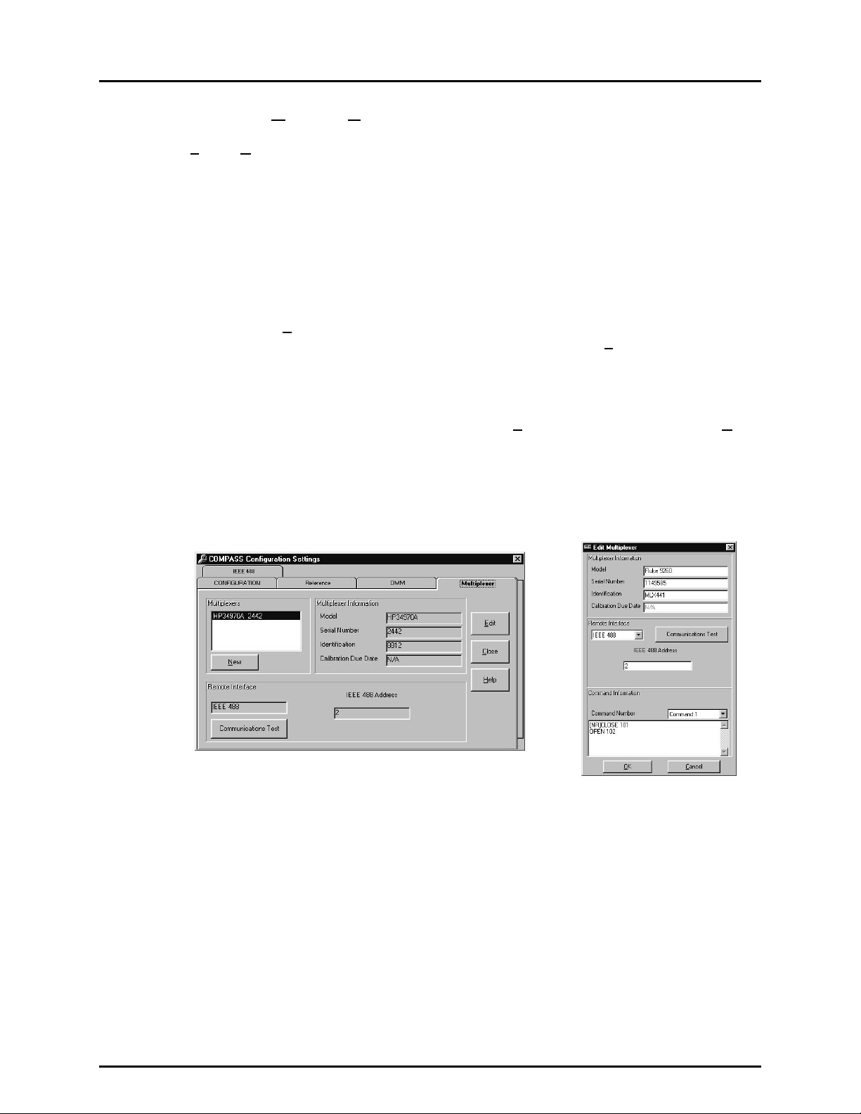
COMPASS® FOR PPC/RPM™ USER’S MANUAL
8.2.4 [TOOLS], [CONFIG HARDWARE], [MULTIPLEXER] TAB
[Tools], [Config Hardware], [Multiplexer] is a tab selected panel used to set up the
multiplexer(s) (MUX) available to COMPASS. The panel allows new MUXs to be created and
existing MUXs to be edited. The MUXs set up in the [Multiplexer] panel are available for selection
when setting up the COMPASS test system in th e [CONFIGURATION] panel (see Se ctio n 8.2. 1 ).
If a MUX is active in the co nfiguration, COMPASS wi ll always use the active MUX c ommand
to switch signals of multiple DMM data acquisition type DUTs onto the currently active DMM.
The [Multiplexer] pane l provides a list of the MUXs ava ilable, disp lays com plete infor mation
on the selected MUX, allo ws the selec ted MUX to be e dited or a ne w MUX to be c r eated. To
select a MUX to view, single click on the MUX name and serial number in the <Multiplexers>
display list (upper left- hand corner ). T o edit an exis tin g MUX, d ouble c lic k on the MUX l istin g
or click on the <E
communications with the currently selected MUX, click on <Co
If settings entered c orrespond to a valid rem ote interface an interface d etected message is
displayed; otherwise an error message is displayed. Unlike other communications tests,
no test command is issued for a multiplexer. The te st determine s the validity of the inte rface setup.
dit> button with the desired MUX highlighted in the MUX listing. T o test
mmunications Test>.
Double clicking on the MU X listing, clicking on the <E
dit> button or clicking on the <New>
button caus es the <Edit Multiplexer> or <Add New Multiplexer> pop-up to app ear. T hese are
identical but distinguished by name to make it clear which task is currently being performed.
The <Edit M ult iplexer> or < Add New M ultip lexer> pop- ups a llow a m ultip lexer devic e to be
set up from scratch or edited from an existing one.
Figure 24. COMPASS Configuration Settings
Screen - Multiplexer
Figure 25. Edit Multiplexer Screen
The purpose of the definit ion fields and settings as well as i nstructions on how to use them
are provided in Tab le 1 4. When defining a new MUX the f ie lds c ome up blank. When editing
an existing device, the fields come up populated with the information on that device.
When editing is complete, click <OK> to save changes.
© 1998-2000 DH Instruments, Inc. Page 46
Page 61

8. THE [TOOLS] MENU
Table 14. [Multiplexer] Tab
FEATURE DESCRIPTION
Model
(required entry field)
Serial Number
(required entry field)
Identification
(optional entry field)
Calibration Due
(disabled entry field)
Remote Interface
(drop-down
selection list)
RS232 Settings
(conditional
display panel)
IEEE 488 Address
(conditional e n try field )
Communications
(action button)
Command Number
(drop-down
selection list)
Command
(required entry field)
Command
Terminator
(drop-down
selection list)
Defines the model of the multiplexer.
Write in the multiplexer serial number.
Write in a device identification, if desired. The field can be used for internal tracking of
MUXs or any other information desired. The value entered will be included in run test data
files and reports.
Multiplexers do not support this entry.
Date
The choices available are <RS232> and <IEE 488>. To set up the MUX for remote
communications, select the interface that is on the MUX. When an interface type is
selected, the rest of the <Remote Interface> and <Command Information> panels
change as appropriate to accommodate definition of the interface characteri stics.
If the remote interface sel ection is RS232, the <RS232 Settings> information is shown.
When creating a new reference device, the settings are loaded with COMPASS default
settings. Port settings are listed baud rate, parity, data bits, stop bi ts. Clicking on any
setting field causes the <RS232 Settings> editor to appear. Select/enter the correct
settings for the multiplexer and click <OK> (see Section 8.2.6).
If the remote interface selection is IEEE 488, the <IEEE 488 Address> entry field is
shown. When creating a new reference device, the IEEE 488 address is set t o the default
address 10. To address can be edited directly in the entry field.
Clicking on the communications test button causes COMPASS to check the validity of the
interface. No test command is issued to the multiplexer. Use [Tools], [Remote
Test
Communications] (see Section 8.4) to send commands directly to the multiplexer.
Identifies the multiplexer comm and number. The command number corresponds to the
DUT position in the <Setup DUT> screen when a test is run (see Section 5.2.1.6). The
actual command is specified in t he <Command> field described immediately following.
When testing DMM data acquisition type DUT(s), with a m ul tiplexer ac tive i n the hardware
configuration, for each DUT a multiplexer command will be sent prior to reading t he DMM.
Command 2 will be sent to the multiplexer before reading DUT 2’s output from the DMM.
Defines the st ring of charac ters which, when sent to th e multiplexer, causes the s witching to
connect the corresponding DUT position to the DMM and isolate all other output lines.
The command entered is the command that will be used for the current <Command Number>.
When entering commands into the <Command> field adhere to the following rules:
Remember that generally, only one channel should be closed at a time, t herefore it is
necessary t o o pen al l cha n nels bef or e c los i ng on e. Thi s m ay re q ui re m ult ipl e c om m ands fo r on e
<Command Number> . To enter multiple commands for one <Command Number>, separate
the commands by pressing <Enter> between commands. Thi s places a carriage returns
between the commands.
Not all multiplexers output a response to all commands. Place an “[NR]” in front of
commands that have no response or COMPASS will time-out waiting for a response. For
example, entering the following commands :
[NR] CLOSE 101
OPEN 102
Causes COMPASS to send the first command “CLOSE 101” and not attempt t o read a
response. Then the command “OPEN 102” will be sent and COMPASS will attempt to
read a response from this command. If a response is not obtained, COMPASS will time-out.
COMPASS does not process t he response of a multiplexer. A response is read from a
multiplexer purely to prevent communic ations problems that can result from not reading a
command that generates a response. The output of the multiplexer will never appear in a
COMPASS data file or report.
Defines how the commands sent to the multiplexer are terminated. The selections
available from the drop-down list are carriage return and carriage return + line feed.
Page 47 © 1998-2000 DH Instrument s, Inc.
Page 62

COMPASS® FOR PPC/RPM™ USER’S MANUAL
8.2.5 [TOOLS], [CONFIG HARDWARE], [IEEE 488]
[Tools], [Config Hardware] , [IEEE 488] is a tab s elec ted panel us ed to set up th e IEE E 488
cards that the computer running COMPASS can use for IEEE 488 communications.
The panel allows a Capital Equipment Corporation (C EC) or National Instrum ents’ IEEE 488
card to be selected and the card address to be specified. The cards setup can then be
selected in the [CONFIGURATION] panel.
The default selections within COMPASS are designed to work with the default Windows setup
of the supported IEEE 488 cards. Unless the host PC has multiple IEEE 488 cards or is
specially configured; a properly installed IEEE 488 card with a default setup will work
with COMPASS. Simply select the card on the [CONFIGURATION] tab (see Section 8.2.1).
This section is provided to display and edit the card address only. Do not confuse the card
address with that of an individual instrument.
The <Card Type> pull down provides the choice of <National Instruments> and
<CEC Capitol Equipment Corp>. Clicking on the <Card Address> field caus es an address
entry pop-up to be displayed. Only one address per card type is supported. This field
represents the address of the IEEE 488 card itself and not any specific instrument. Refer to the
card manufacturer documentation on how to change the address in the card when necessary.
Figure 26. COMPASS Configuration Settings Screen - IEE-488
8.2.6 RS232 SETUP
If the remote interf ac e sel e c tion is R S2 32 f or a n y dev i c e, the <RS 232 S ett ing s> sc reen m ust
be used to determ ine the specific setting information. This is t ypically achieved by clic king
the RS232 settings th at displa y during the setup process. Selec t the correct s ettings for the
device from the dr op-down lists and clic k <OK> when r eady. All settings with the exception
of the <COM Port> are defined by the device that will use the interface. Refer to the
instruction manual of that device to determine these settings and make any necessary
selections for the interface to function in RS232. The <COM Port> port selection should
represent the ph ysical connection of the device and an RS232 port on the host PC or the
currently configured reference device.
© 1998-2000 DH Instruments, Inc. Page 48
Page 63

8. THE [TOOLS] MENU
Use the <Ref Com2> selec tion f ound at the en d of the <CO M Port> drop- down li st to acc ess
the currently configure d ref erence CO M2 port r ather t han a st andar d com m unications p ort on
the host PC. If the reference device does not have a remote interface, CO MPASS will
generate an error when trying to access the port. No special c ommand setup is r equired to
use the <Ref Com2> option. Select this option just as any other COM port selection,
COMPASS will set up the referenc e de v ice COM2 port and m odify the commands as n eeded
to send and receive commands using this interface.
Figure 27. RS232 Settings Screen
8.3 [TOOLS], [OPTIONS]
[Tools], [Options] is used to set up COMPASS operation al preferenc es. [Tools], [Options] is made up
of six tab selected panels including:
[Maintain Lists] Delete items from COMPASS’s automated entry drop-down lists (see Sect ion 8.3 . 1).
[Initialize Test] Set user preferences for steps to include or suppress during test initialization
(see Section 8.3.2).
[Run Test] Set user preferences affecting the run test portion of test execution (see Section 8.3.3).
[Data File] Set user preferences affecting the “data” file (*.dat) which records the data from a test
run (see Section 8.3.4).
[File Locations] View and edit the default locations for the files COMPASS creates and maintains
(see Section 8.3.5).
[Language] Select the language that COMPASS will use (see Section 8.3.6).
Figure 28. Options Screen - Maintain Lists
Page 49 © 1998-2000 DH Instrument s, Inc.
Page 64
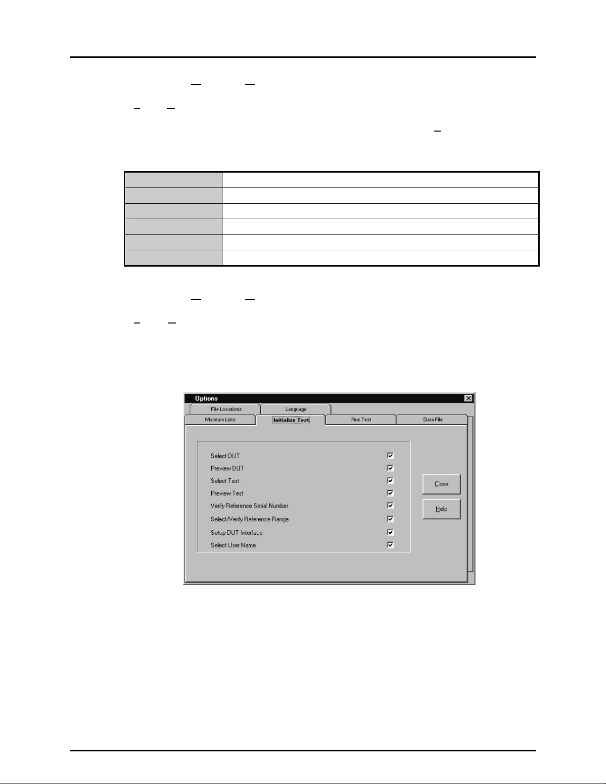
COMPASS® FOR PPC/RPM™ USER’S MANUAL
8.3.1 [TOOLS], [OPTIONS], [MAINTAIN LISTS]
[Tools], [Options], [Maintain Lists] is a tab selected pane l used to delete u nwanted items
from the various lists that COMPASS adds to automatically. To delete an item from a list,
select the item fr om the drop-down list and click the corresponding <D
included are shown in Table 15.
el> button. The lists
Table 15. COMPASS Lists
DUT Manufacturers
DUT Models
Reference Devices
DMMs
Multiplexers
Users
From <DUT Definition/Profile> screen, <Manufacturer> field (see Section 6.2).
From <DUT Definition/Profile> screen, <Model> field (see Section 6.2).
From <Reference> tab (see Section 8.2.2) used in [CONFIGURATION] tab.
From <DMM> tab (see Section 8.2.3) used in [CONFIGURATION] tab.
From <Multiplexer> tab (see Section 8.2.4) used in [CONFIGURATION] tab.
From run test, <Enter User ID> pop-up (see Section 5.2.1.7).
8.3.2 [TOOLS], [OPTIONS], [INITIALIZE TEST]
[Tools], [Options], [Initialize Test] is a tab selected panel used to set user preferences
affecting the init ialization portion of test execution (see Secti on 5.2.1). The test init ialization
steps can be turned ON or OF F to avoi d r epe ati ng un d esir ed or un nec es sary steps each time
a test is run. The panel lists the different steps of test initialization in order of execution.
Clicking on the check box corresponding to the s tep turns it ON or OFF (ON if box checked,
OFF is box is blank).
Figure 29. Options Screen - Initialize Test
The test initialization behavior with initialization steps turned ON or OFF is outlined in Table 16.
© 1998-2000 DH Instruments, Inc. Page 50
Page 65

8. THE [TOOLS] MENU
Table 16. [Initialize Test] Tab
FEATURE DESCRIPTION
Select DUT
(check box)
Preview DUT
(check box)
Select Test
(check box)
Preview Test
(check box)
Verify Reference
Serial Number
(check box)
Select/Verify
Reference Range
(check box)
Setup DUT
Interface
(check box)
Select User Name
(check box)
When OFF, the select DUT step is skipped and the last DUT that has been accessed
(edited, viewed, created or run) is aut omatically used as the selected DUT (see Section
5.2.1.1).
When ON, the selected DUT is previewed. W hen OFF, the DUT preview is skipped (see
Section 5.2.1.2).
If ON, the <Select Test To Run> file box appears. If OFF, the primary test associated
with the selected DUT is automatically selected. If COMPASS cannot access the file
specified as the primary test, then the <Select Test To Run> file box appears even
though this prompt was OFF (see Section 5.2.1.3).
When ON, the selected test is previewed. When this prompt is OFF, the selected test is
automatically accepted without preview (see Section 5.2.1.4).
When ON, COMPASS compares the serial number of the connected reference device
with the serial number specified for the referenc e in the hardware configuration. If the
serial numbers do not match, a warning message appears. If they do match, then no
message appears. When this feature is OFF, the comparison is not performed and no
messages appear (see Section 5. 2.1.5). Verification of reference serial number oc curs
only if the reference can be read remotely.
When ON, COMPASS queries the connected reference to determine what ranges are
available. It then analyzes the test points in the current test to determine the
recommended range. It selects this range by default, but this prompt displays the
alternate ranges and allows the operator to override the def ault selection. If t he prompt is
OFF, COMPASS automat ically accepts its recommended reference range and no prompt
appears (see Section 5.2.1.5). Reference range is verified automatically only if the
reference can be read remotely.
This prompt can only be turned OFF if the DUT file is a DUT definition (i.e. , not a DUT
profile) (see Section 6.2). DUT profiles require <Setup DUT Interface> for identificat ion
of the DUT(s) being run. When this prompt is ON, the <Setup DUT Interface> pop-up
appears to allow changing of DUT communications parameters and testing of DUT
communications (see Section 5.2.1.6).
When ON, the user is prompted to enter his/her nam e (or select it from the drop-down
user name list). This name appears under user in the test data and in reports (see
Section 5.2.1.7). When this prompt is OFF, the last user’s name is automatically select ed
as the user for the current test. Turning OFF this prompt is useful for single user systems
and can even be done after the first run of the day for a specific operator.
8.3.3 [TOOLS], [OPTIONS], [RUN TEST]
[Tools], [Options], [Run Test] is a tab selected panel used to s et user pr ef erences aff ecting
the run test part of test execution (see Sec tion 5.2.2). Vario us aspects of run tes t behavior
can be changed in five main categories:
Audible Feedback On Turns ON and OFF aud ible feedback for various run time
events.
Plot Scaling Affects the scaling of the run screen’s run time plot (see
Section 4.3).
Reference Reading Affects how readings will be taken from the reference
pressure device when running a test.
Default DUT Communications Sets def ault communicatio n parameters f or r eading R S23 2
and IEEE 488 data acquisitio n type DUTs (see Sectio n
Page 51 © 1998-2000 DH Instrument s, Inc.
6.2).
Page 66

COMPASS® FOR PPC/RPM™ USER’S MANUAL
Figure 30. Options Screen - Run Test
The purpose and operation of the run test preferences are defined in Table 17.
FEATURE DESCRIPTION
Audible Feed back On
(check boxes)
Plot data to
tolerance
(check box)
Use set point as
reference reading
in dynamic control
(check box)
These check boxes turn ON and OFF audible feedback associated with run tim e events.
When the box is checked, audible feedback is ON, when the box is blank, audible
feedback is OFF. The run time events and associated sounds are:
<Out of Tolerance>: When running a test, after taking data at each test point, the error of
<Test Complete>: This s ound occurs to alert the operator that t he last pressure point
<Failures>: Failures occur when the pressure has not been set within the
<Manual Entry>: An audible prompt alerts the user any time that a user response is
Affects the run time plot of the run sc reen (see Section 4.3). If the box is checked, the plot
will be scaled to the DUT tolerance (see Section 6.2) and DUT tolerance bars will be
included on the graph. If the box is not checked, t he plot will automatically be scaled and
re-scaled as needed to show DUT error values as the test progresses.
Affects how readings are taken from the referenc e pressure device when a test is run
using a DHI PPC2, PPC2+ or PPCK press ure controller in dynamic control mode. If the
check box is checked, the reference pressure reading will be assumed to be equal to the
target value when a ready condition occurs. If the check box is not checked, actual
momentary reference readings will be used. The default condition is box checked as this
reflects the most comm on use of dynamic control mode. See the pres sure controller’s
Operation and Maintenance Manual for a complete explanation of static and dynamic
control modes and ready/not ready conditions.
This setting has no effect if the reference device is not a DHI PPC2 , PPC2+ or PPCK or
dynamic pressure control mode is not speci fied in the test file or the current test point is
0 (zero) or a VENT, as there is no control under these conditions (see Section 7.2.5).
Table 17. [Run Test] Tab
the DUT relative to the reference is calculated. If this error exceeds
the tolerance specified in the DUT file, an out of tolerance c ondition
can occur (see Section 4.3). An out-of-tolerance condition is
indicated by a low buzz.
in a test has been completed and the <Test Notes> display is being
presented. Test complete is indicated by three short beeps.
pressure setting time-out limit specified in the test file (s ee Section
7.2.5). Pressure setting time-outs are included in leak test, c ycle
pressure and for each pressure point in a test. A press ure setting
time-out is indicated by a buzz of a diff erent frequency than the out
of tolerance buzz.
required to continue test execution (e.g. confirmation of manual
pressure setting, manual reference pressure entry, manual DUT
output entry, etc.). The need for operat or respons e is signaled by a
rapid series of ascending tones.
© 1998-2000 DH Instruments, Inc. Page 52
Page 67

8. THE [TOOLS] MENU
FEATURE DESCRIPTION
Use common
manual reference
pressure for
multiple DUTs
(check box)
RS232 Settings
(display field)
IEEE 488 Address
(display field)
Affects how reference readings are taken when reference readings are entered manually
and multiple DUTs are being tested. I f the box is checked, a single reference press ure
entry will be made common for all of the DUT readings. If t he box is not checked, an
individual reference reading must be entered for each DUT.
This setting has no effect if the reference devic e is not manual and/or the test is not a
multiple DUT test.
Displays the default settings for communicat ions with RS232 data acquisition type DUTs
(see Section 6.2). The information displayed is com port, baud rate, parity, data bits, stop
bits. Clicking on the display f ield caus es the <RS232 Setti ngs> editor to appear allo wing
the default RS232 port and settings to be changed. Use the drop-down list s to select the
desired settings and click <OK> (see S ection 8.2.6). The s ettings selected will appear as
the initial RS232 settings when setting up an RS232 DAQ DUT.
Displays the default IEEE 488 address for communication with IEEE 488 dat a acquisition
type DUTs (see Section 6.2). The IEEE 488 address may be edited directly in the field.
8.3.4 [TOOLS], [OPTIONS], [DATA FILE]
[Tools], [Options], [Data File] is a tab selected panel us ed to set user pref erenc es affecting
the “data” file (*.dat) which records the data from a test run.
The purpose and operation of the data file preferences are defined in Table 18.
Table 18. [Data File] Tab
FEATURE DESCRIPTION
Data Delimiter
(drop-down selection list)
Log File
(drop-down selection list)
Directory Name
(Check box at the bottom
of the display)
This preference sets the data delimiter for the data i n “log” and “data” fil es (*.dat ,
*.log). The choices are comma, tab or sem icolon. Comma data delimi ter is the
default as it is more commonly used. The choice can be useful to assure
compatibility when COMPASS data files will be exported into another program.
The COMPASS internal data and report functions automatically detect and
handle which delimiter was used in the data file s o the choice can be changed
occasionally without affecting COMPASS operation.
When COMPASS runs a test, the data is saved to a *.log file. At the end of the
test the *.log file is saved as a *.dat file (see Section 12.2). This preference
determines whether an individual *.log file will be saved for each test run
(<Save> selection) or the “log” file will be overwritten at each run (<Overwrite>
selection). The *.log file can be usef ul as a backup to recover data lost from a
*.dat file. The default setting is <Overwrite> to minimize the number of files
created automatically by COMPASS.
Not only does COMPASS generate default file names for *.dat files, it also
creates a default directory bas ed on the DUT that the data is taken from (s ee
Section 12.3). This preference allows the directory to be named after the DUT
serial number or the DUT ID. Unlike the ID field, the DUT serial number is a
required field and therefore used by default. If no DUT ID is present, the serial
number is used. This DUT dependent data directory is created as a sub
directory of the directory selected for *.dat files (see Section 8.3.5). The
directory name will include the full text of the serial number or ID of the DUT
unless one of the following invalid characters is part of the field: /, \, ?, :, *, <, >, |,
or “. If so, the directory name will contain all text up to the first occurrence of the
character. In the rare case the first character is invalid, the data file will be
placed in the root *.dat directory.
Page 53 © 1998-2000 DH Instrument s, Inc.
Page 68

COMPASS® FOR PPC/RPM™ USER’S MANUAL
8.3.5 [TOOLS], [OPTIONS], [FILE LOCATIONS]
[Tools], [Options], [File Locations] is a tab selected panel used to view or modify the
default directory path used to store each of the various file classes used by COMPASS.
To edit the director y path for a spec ific f ile class eithe r double clic k on that f ile class or single
click the file class and then click <E
selection of a new path. This tool also allows the creation of new directories. Any new
directories created with this tool will immediately exis t on your computer system or network
(assuming you had the rights necessar y to create the director y). It will not be rem oved if the
edit directory option is subsequently canceled.
The file location path for *.dat and *.rtf (report) files is actually the root directory path
for the DUT serial number or ID based sub-directories that COMPASS creates
automatically (see Section
directories.
dit>. A directory browsing tool appears to allow the
12.3). *.dat files and *.rtf (report) files are stored in the sub-
Figure 31. Options Screen - File Locations
8.3.6 [TOOLS], [OPTIONS], [LANGUAGE]
[Tools], [Options], [Language] is a tab selected panel used to select language
related pr eferences. This feature is provide d in addition to the startup language pr ompt to
allow language selec tions while COMPASS is running (see Section 2.5). Select the desired
language and press <Close>. The new language will not display until COMPASS
is restarted. To avoid the necess ity of th is selectio n, chec k the <Prompt for language> box
at the bottom of the display. When this f eature is enabled, the op ening language selecti on
prompt will appear each time COMPASS is run. Remove the check to prevent the opening
language display.
All COMPASS for PPC/RPM on-line HELP is in English regardless of language selection.
© 1998-2000 DH Instruments, Inc. Page 54
Page 69

8. THE [TOOLS] MENU
COMPASS for PPC/RPM uses the decimal separator set up in the international settings
of Windows. This determines whether the separator is a “.” or a “,”.
COMPASS is run in one language at a time. Any language selection using this option will
not occur until COMPASS is restarted.
Figure 32. Options Screen - Language
8.4 [TOOLS], [REMOTE COMMUNICATIONS]
[Tools], [Remote Communications] provides a simple means of sending individ ual comm and strings to
remote devices and r eceiving and displaying the res ponse. This tool can be used fo r discreet remote
device communication and communications testing. Use this tool for troubleshooting communications
problems and determ ining t he ap pr opriate command to s end pr ior to entering the <Command> value in a
DUT, DMM or multiplex er. If a comm and issued to a device does not give the desir ed results using this
tool, refer to the device manual for any special requirements that must be used to send the command.
This tool allows the desired interface type to be selected and interface parameters to be specified.
IEEE-488 communication assumes use of the IEEE 488 card selected in [T
(see Section 8.2.5). En ter the comm and to be sent in the c ommand field. C licking <S
command to be sent usin g the c urr ent <In terf ace Set up>. Resu lts and return strings are dis p layed in the
<Last Command Reply> box. These return strings are logged as rea d and unmodif ied by COMPASS.
The communications time-out is 10 seconds. A time-out is indicated by displaying <COMPASS TIME-OUT>.
If the command does not have a response or the target communications device does not normally
respond to commands, click the <Send Only> check box or COMPASS will expect a response and
time-out if none is recei ved. Comm ands sent are automatically added to the drop-down <Command> list;
the list is cleared each time COMPASS is run.
ools], [Config Hardware]
end>, causes the
Page 55 © 1998-2000 DH Instrument s, Inc.
Page 70

COMPASS® FOR PPC/RPM™ USER’S MANUAL
Figure 33. Remote Communications Screen
© 1998-2000 DH Instruments, Inc. Page 56
Page 71

9. THE [DATA] MENU
99..
T
T
HHEE
[[D
D
A
AATTA
M
]] M
U
EENNU
9.1 OVERVIEW
The [Data] m enu acc esses too ls that wor k direct ly with COMPASS *.dat files. T he *.dat f iles cont ain the
data acquir e d during a test run (see Section 12). The data to o ls al l o w t he “data” file t o b e v ie w e d a n d pr i nt e d.
There is also a plotting t ool to produce and print a variet y of error plots for *.dat files. T hese tools are
provided to allow co nve nient a cce ss to te st data wi th out cre a ting comple te test rep orts (se e Secti on 1).
9.2 [DATA], [VIEW TEST DATA]
[Data], [View Test Data] is used to view the *.dat files in which test data is stored (see Section 12.3).
When [D
directly set to the default * . dat directory (see Section 8.3.5). Selecting a f ile, c aus es that f ile t o be o pened
and displayed without form atting in the COMPASS <Data Viewer> sc reen. This display is provided to
view data files onl y. There are no opt ions to edit and/ or save data f iles us ing this featur e. T he nam e and
directory path of the *.dat file currently being plotted is shown at the top of the window.
While viewing a data file, a [F
ata], [View Test Data] is selected, a s tandard Windows file browser appears with the default
ile] menu is available. The [File] menu choices are:
[S
elect New Data File] To pick a different *.dat file to view.
[Print] To print the *.dat file that is being viewed using the standard Windows print function.
[Exit] To leave the view test data function.
Figure 34. Data Viewer Screen
Page 57 © 1998-2000 DH Instrument s, Inc.
Page 72

COMPASS® FOR PPC/RPM™ USER’S MANUAL
9.3 [DATA], [PRINT TEST DATA]
[Data], [Print Test Data] is used to print raw data files.
When [D
directly set to the default *.dat directory (see Section 8.3.5). Selecting a file causes the standard
Windows print function to open allowing the file to be printed with any printer that is set up.
ata], [Print Test Data] is selected, a standard W indows file browser appears with the default
“Data” files may also be printed from within [View Test Data] by selecting [File], [Print].
9.4 [DATA], [PLOT TEST DATA]
[Data], [Plot Test Data] is used to ge nerate error plots of DUT readings vs . reference rea dings from the
data contained in *.dat files. The plots generated may be viewed and/or printed. T his func tion is us ef ul to
quickly analyze data. The plots may also be selected for inclusion in COMPASS reports
(see Section 10.4.3).
Calculations used to produce data plots are documented in Section 14.
When [D
that holds the *.dat f iles. Selecting a file ca uses the <Plot> screen to appear loade d with an error plot
generated using the data from the *.dat file.
ata], [Plot Test Data] is selected, a s tandard W indows file browser app ears set to the director y
Figure 35. Plot Screen
The name and director y path of the *.dat f ile curr entl y being plott ed is sho wn at th e top of the p lot screen.
Under the plot itself is a su mmar y of the DUT inf ormation. Two m enu choices are availa ble from the plot
screen: [F
menu choices select different plots for the current *.dat file (see Section 9.4.1) and change plot scaling.
© 1998-2000 DH Instruments, Inc. Page 58
ile], [Plot]. The [File] menu allows a d ifferent *.dat file to be selected f or plotting. T he [Plot]
Page 73

9. THE [DATA] MENU
9.4.1 [DATA], [PLOT TEST DATA], [FILE]
The [File] menu includes menu choices to:
[S
elect Data File] Allows selection, using a standard W indows file bro wser, of a diff erent
data file to be plotted.
[P
rint Graph] Allows the graph currently selected to be printed using the standard
Windows print function.
[E
xit] Exits the [Plot Test Data] function.
9.4.2 [DATA], [PLOT TEST DATA], [PLOTS]
From the [Plots] menu, five dif ferent error plots can be generat ed and the plot scaling can
be changed. The current plot choice is indicated by a check mark by that menu item.
The menu choices are:
rror vs. Reference] Creates a graph of the DU T er ror vs . the ref er enc e
[E
in the DUT pressure units.
[Best F
[Error a n d B
[%D
[%Reading Error vs. Reference] Creates a graph of the DUT error vs. the r ef erenc e
[Di
it Error vs. Reference] Creates a graph of the DUT error vs. the ref er ence
in the DUT pressur e units after fitting the DUT to
the reference using a simple regression, best fit
straight line.
est Fit Error vs. Reference] Creates a graph of both the Error vs. Reference
and Best Fit Error vs. Reference in one plot (see
immediately above).
UTspan Error vs. Reference] Creates a graph of the DU T er ror vs . the ref er enc e
in percent of span of the DUT.
in percent of reading of the reference.
splay Tolerance] Causes any displayed graph to include tolerance bars
and to scale to 1.5 times the tolerance. The tolerance
is the tolerance of the DUT that was tested as
specified in the *.dut file (see Section 6.2).
Selecting [Di
ON and OFF conditions. If the menu choice is
checked, display tolerance is ON and tolerance
bars will be shown on any displayed graph. If the menu
choice is not checked, display tolerance is OFF,
no tolerance bars will be shown and any graph
displayed will automatically scale to the pl otted er rors.
splay Tolerance] toggles between
Tolerance bars are not plotted when the selected plot uses a scale that the tolerance
specified in the *.dut can not be converted to. The %Reading plot when the DUT tolerance
in the *.dut file was specified as %DUTspan, nor are they plotted
Page 59 © 1998-2000 DH Instrument s, Inc.
Page 74

COMPASS® FOR PPC/RPM™ USER’S MANUAL
N
N
OOTTEES
S
© 1998-2000 DH Instruments, Inc. Page 60
Page 75

10. THE [REPORT] MENU
1100.. T
T
HHEE
[[R
R
EEPPOORRT
T
]] M
M
U
EENNU
10.1 OVERVIEW
The purpose of the COMPASS Report Editor is to generate test r eports fr om *.dat files, vie w the reports
and edit them.
The COMPASS Report Editor can be accessed in three ways: by using the [Rep ort ] menu option or pressing
the <G enerate Report > button in the Test Com plete Screen from within COMPASS (see Section 5.2.3),
or from outs ide COMPASS b y clicking the assoc iated icon in th e COMPASS for PPC/RPM program grou p.
In all cases the report editor runs as stand alone application and can be closed at any time without
affecting COMPASS.
10.2 REPORT PRINCIPLES
The COMPASS Report Editor is used to create templates (*.tpl) that are merged with *.dat files to
generate a report. Several r epor t templates can be created t o ha ve c us tom reports to support a vari ety of
report styles. All basic word process ing features are inc luded to allow custom formatting, cut and p aste
ability, changing font t ypes and point size, inserting o bjects, etc. Several report s and templates can be
viewed, edited, saved or printed within the report editor at the same time.
Only the top most file displayed within the COMPASS Report Editor is acted on by the tool bar and
menu selections unless or the selection specifically refers to “All. “ The [OPTION} functions are not
file specific.
The report editor includ es a Test Data Field Insertion Tool. This tool allows link s to fields in COMPASS
*.dat files to be em bedded into the report template. The abil ity to insert *.dat file links at an y location
within a report template us ing any available text formatting is one of the m ost important features of the
report editor. Acces s this tool by pressing <CTRL+T>, the toolbar short cut <Insert Field Key>, or the
menu option [Format], [Insert Field Key] (see Section 10.3.3.2).
The default directory locations for *.dat, *.rtf, and *.tpl files are those specified in the COMPASS
main program (see Section 8.3.5). Each file selection box within the report editor defaults to one of these
directories depend ing on the type of file req uired. Unless changed by the user, all report tem plates are
stored in the ..\template sub-directory of the COMPASS root directory. The <Current Template>
selection on the bottom s tatus bar of the m ain disp la y is alwa ys used to g enera te a repor t. T his selectio n
can be changed by using [Format], [Select Template].
Reports generated automatically have the same name as the *.dat file that was merged but with the
extension *.rtf. By default they are stored in the s ame directory as the data file in automatic DUT serial
number based sub-directories (see Section 12.3). Report file location can be changed by selecting
ols], [Options] , [File Lo cations] within the COMPASS main program (see Section 8.3.5). If the report
[To
file directory is not the same as the data file directory, automatic sub-directories will not be made or used.
The COMPASS Report Editor supports Windows dr ag and drop functional ity. All supported f iles of the
report editor can be dra gged to the title bar of the program from Windows Explorer. Depending on the
type of file, the report editor will either generate a report or display the file (see Section 10.10.1).
Page 61 © 1998-2000 DH Instrument s, Inc.
Page 76
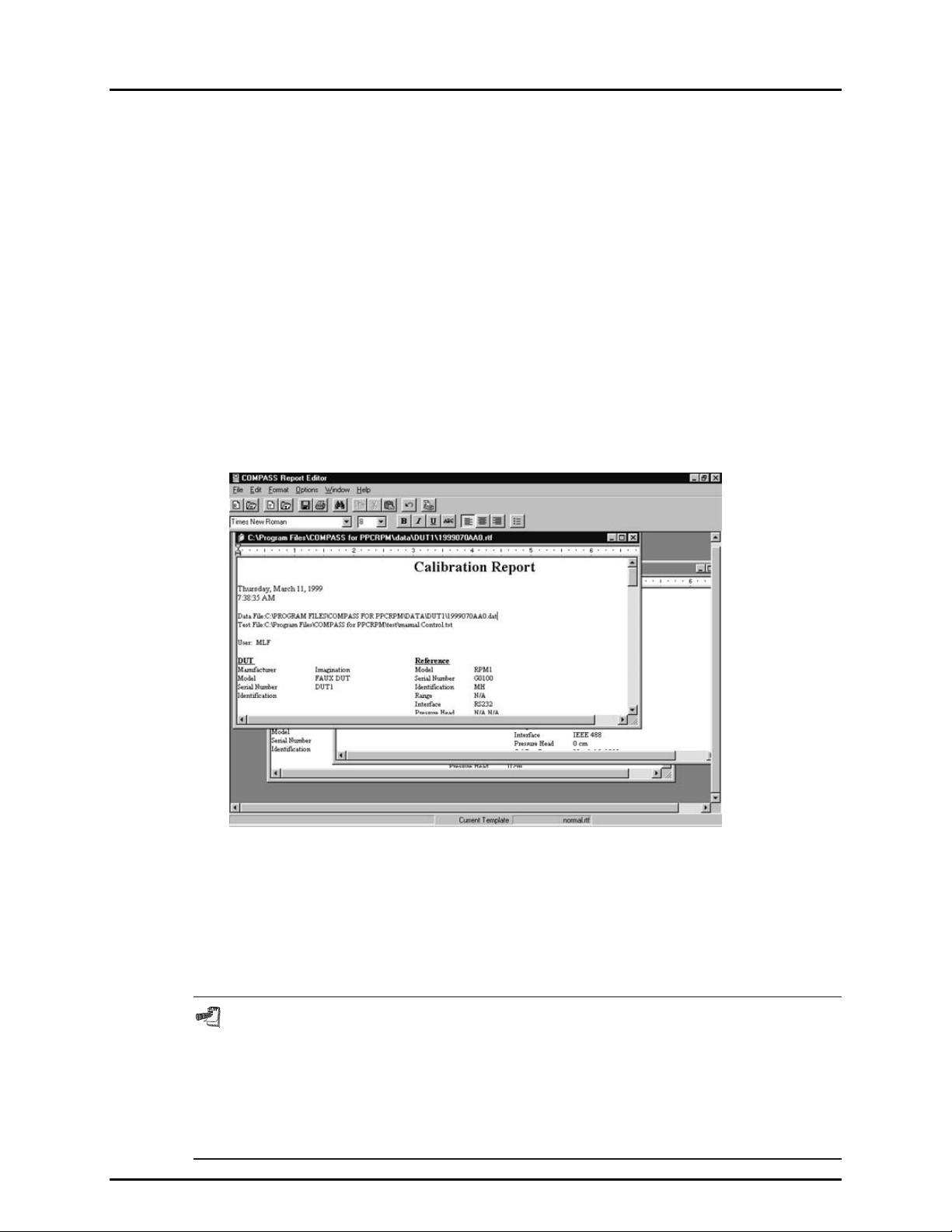
COMPASS® FOR PPC/RPM™ USER’S MANUAL
10.3 MAIN MENU BAR
The main menu of the report editor is divided int o several sec tions each with a separate funct ion. Many
of these functions can also be accessed by a shortc ut included on on e of the COMP ASS Report Editor
toolbars. Each menu is summarized immediately below and covered in detail in subsections of this section.
[File] Print, save, open and close reports (*.rtf) and report templates (*.tpl) (see Section 10.3.1).
[Edit] Search, cut and paste text. These features are also ava ilable using th e toolbar and s tandard
Windows shortcuts (see Section 10.3.2).
[Format] Insert information an d change the page m argins of the current top fil e displa yed (see Section
10.3.3).
[Options] Toggle the display state of toolbars (see Section 10.3.4).
[Window] Change the current top W indow within the COMP ASS Report Editor display. This changes
the file which will be acted on by the menu options (see Section 10.3.5).
[Help] Access on-line help (see Section 10.3.6).
Figure 36. COMPASS Report Editor
10.3.1 [FILE] MENU
Detailed inf ormation o n each of the it ems in the [File] menu is listed in th is section. Items that
have an equivalent toolbar shortcut, display the icon of the tool bar next to the section title.
Multiple files can be selected using many of the [File] menu options. Specifically, when
selecting a *.dat file to generate a report or selecting a *.rtf or *.tpl file to edit a report or report
template. Use the Shift and arrow keys to highlight the desired files within the Windows
file selection tool when making a multi-file selection. The function that generated the file
selection will act on all files selected. For example, generating reports starts with the
selection of *.dat files. Selecting several *.dat files in the file box will generate a separate
report for each file selected. It is a short cut to selecting each file one at a time.
© 1998-2000 DH Instruments, Inc. Page 62
Page 77

10. THE [REPORT] MENU
10.3.1.1 [FILE], [EDIT REPORT]
[Edit Report] is used to edit an existi ng report. Selec ting this featur e displa ys a
standard Windows file selection tool set to the directory containing the data
sub-directories in which reports are stored (see Section 12.3). The selected
report file opens in th e editor where it ca n be edited as des ired. Use the [File],
[Save] feature or the toolbar shortcut to save the file.
10.3.1.2 [FILE], [GENERATE REPORT]
[Generate Report] is used to create new test reports f rom test “ data” files (*.dat)
and a template file (*.tpl). T he firs t step is to s elect a *.dat f ile usin g the stan dard
Windows file selection tool. As previously described at the beginning of this
section, a single *.dat or multiple *.dat files can be selected. The COMPASS
Report Editor merges the selected *.dat file(s) with the current template to
generate the report. T his task is perform ed by loadin g the templat e into m emor y
then replacing every field key with the corresponding piece of data file
information. Al l formatting char acteristics of the f ield ke y that are present in the
report template are maintained during report generation. The final report is
automatically saved a nd loaded into the r eport editor. At this point the report f ile
can be acted on like any other document within the report editor.
Prior to using this option, make sure the desired report template is selected by
noting the name of the file on the bottom status bar’s <Current Template> field.
If no template displays or you wish to change the template, use [Format],
[Select Template] to select the desired template (see Section 10.3.3.3).
10.3.1.3 [FILE], [EDIT TEMPLATE]
[Edit Template] is used to edit an existing tem plate. This can be used eith er to
change an existing template or to create a new template similar to an old
template. For example, if an existing template contains a standard header, footer
and formatting, it m ay be sim pler to create a ne w template b y editing an ex isting
template and saving to a new name than to start a new template from scratch
(see Section 10.4.5). Template files can ha ve either a *.rtf or *.tpl extens io n. It is
preferred that *.tpl be used as the file extension for newly created templates.
This extension is more descripti ve than the *.rtf extension which is prov ided for
compatibilit y with previous ver s io ns of COMPASS.
The first step is to select the tem plate file to edi t using the W indows file select ion
tool that displa ys after this opti on is selected . The selec ted template dis plays in
the report editor. Edit all constant t ext that you wish to display on every repor t.
Use the format toolbar a nd menu f eatures of the r eport edi tor to mak e any visual
edits desired. To insert a data file link use the [Format], [Insert Field Key]
menu option or toolbar sho rtcut (see Se ction 10. 3.3.2) . A fte r all e dit s have b een made,
save the template. At this point the template has n ot been selected for report
generation unless it is already listed in the <Current Template>. To use this
template for a report f irst select the template usin g [Format], [Select Template]
then select [File], [Generate Report] to create the report (see Section 10.3.1.2).
Page 63 © 1998-2000 DH Instrument s, Inc.
Page 78

COMPASS® FOR PPC/RPM™ USER’S MANUAL
The font and paragraph format of a field key is maintained during report
generation. As a result the “data” file information that the field key
represents will be inserted using the font and alignment characteristics of
the field key. For example, if the “data” file key in a template uses a font
point size of 20 with bold text. The “data” file name will display in the
completed report with a font point size of 20 and also have bold text. Keep this
in mind when generating a report template.
10.3.1.4 [FILE], [CREATE TEMPLATE]
[Create Template] is provided to c reate a tem plate from scratch. W hen used, a
new blank report template will be opened for edit. The report template defines the
information fr om COMPASS *.dat files that will be incl uded in the report. It also
defines the fixed information and the report format. A typical report template
includes a customized header and footer, data labels and embedded links to
“data” files. The flexibility of report tem plates and the ease with which they can
be created and edited allo w COMPASS test reports to be personalized to your
exact requirements. T he first step is to add constant tex t that should appear on
all reports generat ed with this tem plate. Com pany specif ic inform ation is a good
example of constant tex t. If the template is being cr eated for a spec ific model of
DUT, constant inform ation spec ific to this model c ould be entered. W hen all t ext
is entered and form atted as desired use [Format], [Insert Field Key] to insert
data file links using the Field Insertion Tool (see Section 10.3.3.2 for more
information on how this to ol works). Although field keys can be enter ed at any
time, it is recom mended that they be entered after constant text to prevent the
chance of corrupting th e field key. Regardless of the approach, the fi nal step is
to save the template with a descripti ve name that will mak e it easy to distingu ish
from other files. T o choose the template for report generation, select [Format],
[Select Template]. Creating and/or editing a template does not make it the
<Current template> selection of the COMPASS Report Editor.
[File], [Create Template] is provided to create a template from scratch. This
is a more advanced report feature that should only be used after the report
generation process is thoroughly understood. It is a much simpler task to
edit an existing template and save that template with a different file name
(see Section 10.4.3). Try editing the sample template “Normal.rtf” provided
with COMPASS.
10.3.1.5 [FILE], [SAVE]
[Save] acts on the c urrent top file in t he report editor. If the current top f ile has
previously been named, the name of the file will appear in the title bar of the
text window. Choosing [Save] in this case saves the current contents of the
window to the current file name with no further prompts. Files that have not
previously been sa ved displa y <Untitled> in their window caption. Saving these
files generates a prompt for the entry of the path and file name of the file. By default,
the file path is set up using the [Tools], [Options], <File Locations> preference
(see Section 8.3.5). If you wish to save the file in another location, do so
realizing the COMPASS Report Editor will no longer know the location of the f ile
unless the COMPASS <File Locations> preference is changed.
© 1998-2000 DH Instruments, Inc. Page 64
Page 79

10. THE [REPORT] MENU
10.3.1.6 [FILE], [SAVE AS]
[Save As] is used to save the cur rent top file with a different nam e, essentially
making a copy of the file. The option always displays a file selection box allowing
the entry of a new file name and follows the same procedure as the [Save]
option when an untitled file is saved (s ee Secti on 10.4 . 5) .
10.3.1.7 [FILE], [SAVE ALL]
Unlike the other save options, [Save All] acts on all documents open in the
report editor. It is the equivalent to selecting each file and choosing [File], [ Save]
(see Section 10.3.1.5). Untitled files will still require the in put of a new file nam e.
This is a shortcut save option that can be used when multiple f iles have been
modified and you wish to save the changes to all of them.
10.3.1.8 [FILE], [CLOSE]
[Close] has the same f unction as press ing the c lose <X> in the W indows contro l
box of any open document. It closes the current file, unloading the contents
from memory. If changes hav e been made to the document s ince the previous
save, a prompt to save the file occurs. Choosing <Yes> saves the file ap plying
the rules of the [File], [Save] optio n. Se lect ing <No> closes the f ile i gnor ing an y
changes that may have occurred.
10.3.1.9 [FILE], [CLOSE ALL]
[Close All] is a short cut to selectin g every file c urrentl y open in the re port editor
then choosing [File], [Close] (see Secti on 10.3.1 .8). T his is a conven ient way to
close several open f iles. If changes ha ve occur red ther e is still a prom pt to save
the file before closing. W hen several files are being closed, an extra opt ion is
provided to automatic ally save an y changed files prev enting the need to m ake a
selection for each file. The prompt displays only after a changed file is
encountered and more than one file is currently open.
10.3.1.10 [FILE], [PRINT]
[Print] is used to print th e cu rr e nt fi l e to a ny printer setu p on t he P C in use. A printer
setup window displa ys prior to printing allowing a pr inter to be selected and set
up before printing. T he COMPASS Report Editor prints the document exactl y
as it is displayed with in the report ed itor unless a pri nter specif ic issue override s
a document feature. Since all printers do not support the same font set, it is
possible for one printer t o print as expected whi le a not her prin ter do es not. If th is
is the case, refer to your printer’s operation manual for instructions.
10.3.1.11 [FILE], [PRINT ALL]
[Print All] displays one printer setup dialog and prints all open documents
according to the printer settings. This feature is provided as a short cut to
selecting the [File], [Print] option for each open file (see Section 10.3.1.10).
10.3.1.12 [FILE], [EXIT]
Selecting [Exit] closes the report editor.
Page 65 © 1998-2000 DH Instrument s, Inc.
Page 80

COMPASS® FOR PPC/RPM™ USER’S MANUAL
10.3.2 [EDIT] MENU
The [Edit] menu provides common word processor editing functions. Many of these
functions have several possible shortcuts. The toolbar and short cut keystrokes provide
direct access to many editing features. All edit functions act on the current document only.
A right mouse click in any open document accesses a mini edit menu with the basic
edit options.
10.3.2.1 [EDIT], [UNDO]
[Undo] is provided to undo the most recent editing operation within the report
editor. Undo support in the COMPASS Report Editor does not provide the
ability to undo several previous steps. Only the most recent step per open
document is mainta ined in the undo buffer. As a res ult, the first tim e [Undo] is
activated the most recent step is undone. The next time it is activated it will
Redo this step becaus e that is what is required t o undo the last action. This is
essentially a toggle between undo and redo.
10.3.2.2 [EDIT], [CUT]
[Cut] deletes the current selection and copies it to the Windows clipboard.
This information can be pasted into other applications or other locations within
the COMPASS Report Editor.
10.3.2.3 [EDIT], [COPY]
[Copy] copies the current selection to the Windows clipboard without first
deleting it. The information can be pasted into other applications or other
locations within the COMPASS Report Editor.
10.3.2.4 [EDIT], [PASTE]
[Paste] copies the contents of the Windows clipboard to the current cursor
location in the document.
10.3.2.5 [EDIT], [FIND]
[Find] provides the ability search for specific text within a report or report
template. Enter the search text in the <Find What> field a nd choose the searc h
options then press <Find>. T he sear ch begins at th e c urrent c ursor loc atio n and
continues to the end of the docum ent. T he firs t occurrence of the searc h text will
be highlighted in the c urrent document. T o repeatedly search f or the same text,
use the shortcut key CTRL+F.
© 1998-2000 DH Instruments, Inc. Page 66
Page 81

10. THE [REPORT] MENU
Figure 37. Find Text Screen
Table 19. <Find> Screen
FEATURE DESCRIPTION
Find What
(required entry field)
Match Case
Find Whole Word
Cancel
The text entered in this field is the search text.
Select this feature when the search should match both case and text.
Causes search to ignore occurrences of the search text that are
embedded in other words.
Only
Starts the text search according to information provided on the form.
Find
Closes the search tool.
10.3.2.6 [EDIT], [FIND NEXT]
[Find Next] performs another text s earch using the most recent sear ch criteria
(see Section 10.5.5). It is most efficient to use the shortcut key combination
[CTRL]+F instead of making a menu selection.
10.3.2.7 [EDIT], [SELECT ALL]
[Select All] highlights all text in the act ive document. Mos t frequentl y, selecting
all text is done to co py the information to later paste it in another appl ication or
open document. The selected text can also be deleted to clear an entire
document of all text.
10.3.3 [FORMAT] MENU
10.3.3.1 [FORMAT], [INSERT DATE/TIME]
[Insert Date/Time] adds the current system date and time to the active
document according to the f ormat specified in the W indows Regional S ettings of
Control Panel. The text is always be entered at the current text insertion point.
10.3.3.2 [FORMAT], [INSERT FIELD KEY]
[Insert Field Key] displa ys the Field Inserti on Tool which is used to embed link s
to COM P ASS “data” files into report templates. The toolbar icon displayed
above or [CTRL]+T are shortcuts to displaying this tool.
To embed a link using the field insertion tool, place the cursor in the report
template at the desired loc ation of the link. Pres s [CTRL] + T to invoke the Data
Field Insertion Tool. The tool appears over the top o f the open report template.
The “data” file fields available are sorted into “field categories”. Select a
<Field Category> by clic king on the des ired category. Then sel ec t a <F i e ld Na me>
Page 67 © 1998-2000 DH Instrument s, Inc.
Page 82
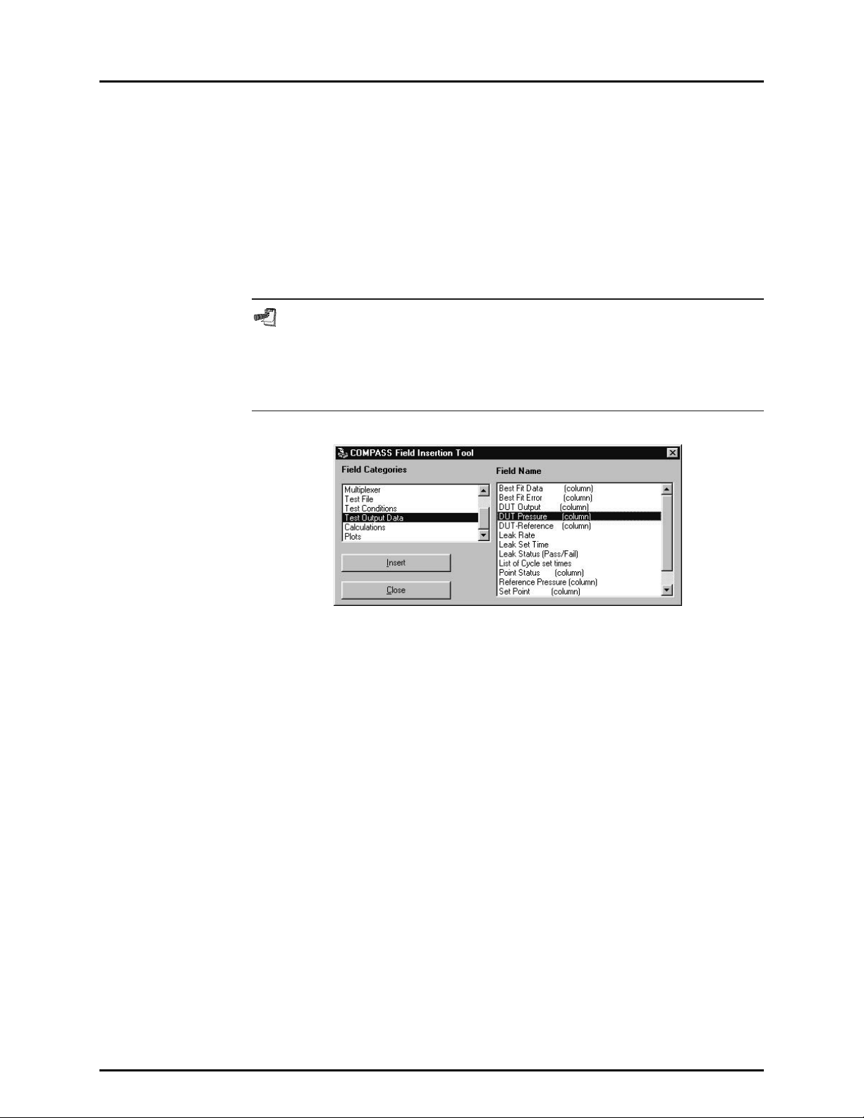
COMPASS® FOR PPC/RPM™ USER’S MANUAL
by clicking on the desir ed field name. The scroll bar s may be used to move up
and down in the category and name lists. Once the field name has been
selected, click the <Insert> button to embed the link into the document at the
current cursor locat ion and close the Data Field Ins ertion Tool. The embedde d
link appears as a character string (e.g., $DUT_MNF$). The character strings
have consistent and intuitive structure to help identify them in use
($category_field name$, except data in columns such as output data has two $$).
Do not edit the link character s trings or they will n o longer o perate. T he y can be
cut and pasted to new locations so long as care is taken not to alter them. The formatting
present in the docum ent at the c urre nt ins ertio n po int is appl ied to th e fiel d link and
to the data imported data from the test data file when the template is merged.
It is a good idea to use tabs to fix field key locations when column alignment
is desired in a report. Using spaces does not always give the desired results.
Text can vary in size based on the selected font. This moves the relative
location of an inserted field preventing the desired column alignment. Click the
<Ruler> to create a tab or adjust an existing tab to get the desired effect.
Figure 38. Data Field Insertion Tool Screen
10.3.3.3 [FORMAT], [SELECT TEMPLATE]
[Select Template] displays a standard Windows file selection tool set to the
template directory specified by COMPASS (see Section 8.3.5). The selected
template name appears on the bottom status bar as the <Current Template>.
All reports generated will use this file as the report template u ntil the selection changes.
The most r ecent <Current Template> is saved by the COMPASS Report Editor.
So, this field does not requi re regular updating unle ss the templ ate to use change s.
10.3.3.4 [FORMAT], [PAGE SETUP]
[Page Setup] is provided to change the margins of the active document. By
default, all page m argins ar e 0.5 inc hes on ne w docum ents. Use the [↑] and [↓]
arrow keys to modif y the page margins. Each k ey press corresponds to a 0.1
inch margin incr ement in the d irection of th e arrow. A margin valu e can also be
entered manually. Margin changes are not reflected on the active document.
The margin change is evident only after printing the file.
© 1998-2000 DH Instruments, Inc. Page 68
Page 83

10. THE [REPORT] MENU
Figure 39. Page Setup Screen
10.3.4 [OPTIONS] MENU
The [Options] menu is the only main menu option that does not depend on the
active document. The options in this menu toggle the display state of the program’s toolbars.
10.3.4.1 [OPTIONS], [TOOLBAR]
The [Toolbar] refers to the main toolbar containing shortcuts to many of the
file options. Selectin g this it em toggl es the dis play sta te of the too lbar. Ref er to the
previous sections for specific information on how to use these toolbar shortcuts.
Figure 40. COMPASS Report Editor, Main Toolbar
10.3.4.2 [OPTIONS], [FONT FORMAT BAR]
The [Font Format Bar] provides access to standard font and paragraph
formatting options. The purpose and use of each option on this toolbar are
summarized in Table 20. Each selection on the [Font Format Bar] can be used
to affect a range of text b y highlighting the desire d text then making a selectio n.
When a text range is not selected, any [Font Format Bar] selection wi ll effec t all
text entered at the current insertion point only. This toolbar also displays the
formatting in place at the current insertion point when a sel ection is not made.
Using the arrow ke ys to move within the text of an open document refreshes this
toolbar with the current text formatting at the cursor insertion point.
Figure 41. COMPASS Report Editor, Font Format Bar
Page 69 © 1998-2000 DH Instrument s, Inc.
Page 84

COMPASS® FOR PPC/RPM™ USER’S MANUAL
FEATURE DESCRIPTION
Font Selection
Font Size
Font Bold
Font Italic
Font Underscore
Font Strikeout
Left Justify
Center
Right Justify
Bullets
Table 20. Font Format Toolbar
Displays and changes the current f ont. A complete list of all fonts
supported by the PC displays in the font selection box.
Displays and changes the current font size. Enter the numerical
value of the desired font size and press [ENTER]. Each value
entered or present in the document is added to the list of available
font sizes and can be selected using [↓].
Displays and changes the current font bold setting. [CTRL]+B is a
shortcut to this toolbar item. This font is in bold.
Displays and changes the current font it alic setting. [CTRL]+I is a
shortcut to this toolbar item. This font is in italics.
Displays and changes the current font underscore setting.
[CTRL]+U is a shortcut to this toolbar item. This font uses an
underscore.
Displays and changes the current font strike out setti ng. This font
uses a the font strike out.
Displays and changes the paragraph justification to left. Left
justification forces all text to begin at the current left indent ation point
(see Section 10.7.3). Only one style of jus tification can be used per
paragraph.
Displays and changes the paragraph jus tification to center. When
active, text is centered between the lef t and right indentation points
(see Section 10.7.3).
Displays and changes the paragraph justification to right. When
active, text is aligned to the right indentation point of the docum ent
(see Section 10.7.3). Most commonly this is the right margin.
Adds or removes bullets to a paragraph.
10.3.4.3 [OPTIONS], [RULER]
The Ruler gives a visual indication, in inches, of the document layout. At all
times the left mos t position of the ruler corresponds to the lef t margin setting of
the document. Changes in the m argin settings will not reflect on the ruler (see
Section 10.6.4). T he COMPASS Report Editor uses the ruler mainl y to support
tab positioning and paragraph indentation. Table 21 gives a functional
description of the options present on the Ruler toolbar.
Tabs and indent values are adjusted by using the mouse to click and drag
the tool to the desired location. Where the mouse button is released
determines the new location of the indent or tab.
© 1998-2000 DH Instruments, Inc. Page 70
Page 85

10. THE [REPORT] MENU
Figure 42. COMPASS Report Editor, Ruler
Table 21. Ruler
FEATURE DESCRIPTION
Sets or displays the left indentation point of the first line of a
paragraph. The ruler location of this indent always displays as the
Left Indent
Left Hanging Indent
Right Indent
number of inches from the left margin.
Sets or displays the left hanging indent of subsequent lines in a
paragraph. Using the mouse, click the left hanging indent image and
drag it to the desired locati on then release the mous e button to drop
it. This parameter has no effect on the first l ine of a paragraph and
can be greater than or less than the left indent.
Sets or displays the right indentation point of a paragraph. Unlike the
left indent properties, the right indent affects the entire paragraph.
The ruler location of this indent always displays as the number of
inches from the left margin.
Sets or displays the location of all tabs that effect the current
T
insertion point. To add a tab, click t he ruler where you want the tab
Tab
to be located, a “T”l appears indica ting t he new ta b locati on. A djust t ab
locations by using a mouse drag and drop operation. Right click a
tab to remove it from the ruler. A Windows standard tab of 0.5 inches
is always present, even when no other tabs display on the ruler.
A maximum of 15 tabs can be used to effect a single range of text.
10.3.5 [WINDOW] MENU
The [Window] menu contains a list of the file names of all open documents in the COMPASS
Report Editor. Any document selected in the list becomes the current top document in
the editor. As an alternative to using th is menu feature, clicking an y open document in the
display can make it the current top document.
10.3.6 [HELP] MENU
The [HELP] menu accesses the COMPASS Report Editor on line help.
[S
how Help] opens the Help function to the C ontents screen fr om which help functio ns can
be accessed.
earch Help] opens the Help function to a standard keyword search tool.
[S
10.4 REPORT EDITOR AUTOMATION
The COMPASS Report Editor supports several Windows automation features which allow the report editor to
be used with other applications. The intent of these features is to allow another application to cause the report
editor to generate a report using COM P ASS data files. There is no intent for the COMPASS Report
Editor to act as a generic reporti ng tool for other applications. O nly *.dat files generated b y COMPASS
can be merged to successfully produce reports. All other files are opened as documents in the editor.
The automation features of the COMPASS Report Editor are advanced topics requiring information
beyond the scope of this manual. This information is provided for advanced users. There is no intent
for the COMPASS Report Editor to act as a generic reporting tool for other applications. Only *.dat
files generated by COMPASS will successfully produce reports. All other files are opened as
documents in the editor.
Page 71 © 1998-2000 DH Instrument s, Inc.
Page 86

COMPASS® FOR PPC/RPM™ USER’S MANUAL
10.4.1 DRAG AND DROP
The COMPASS Report Editor supports standard Windows file drag and drop features.
A set of file names can be dragged to the title bar of the COMPASS Report Editor from
Windows Explorer or th e <Test Conclusion> screen (see Section 5.2.3). A ll *.dat files will
automatically generate a report in the report editor using the current report template.
All other files automatically open for editing in the report editor.
10.4.2 COMMAND LINE ARGUMENTS
COMPASS uses comm and line arguments an d DDE (Dynam ic Data Exchange) to ge nerate
reports in the report ed itor after the completion of a test. Running th e COMPASS Report
Editor with a comm and line of data file names s eparated by the pipe ch aracter “ |” generates
a separate report for each data file using the cur rent report template. T he command line is
accessed using the shortc ut target property of an ico n in Windows. Familiar ity with creating
and editing Windows icons is required to use this feature. Refer to the Windows
documentation and Help for details.
10.4.3 DDE (DYNAMIC DATA EXCHANGE)
The COMPASS Report Editor has an object th at ac ts as a DDE source that can be c ha nge d
to generate a report or open docum ents. To simplify the DDE exchange, the report editor
acts as a source instead of a destination to avoid the requirement for a user setup in the
report editor. The three ba sic requir em ents to esta blis h a DD E link are the applic ation nam e,
link topic and link item. These values respectively correspond to: “COMPASS Report
Editor”, “mdiReprt” and “lblDDE.” Us e these valu es with the DD E destinatio n application to
initiate the DDE link . Poke data file names s epar ate d b y a pipe c harac t er “ |” into the “lblDDE”
source to generate reports. Poke refers to the technique of setting data in a DDE source
using a DDE destination application.
© 1998-2000 DH Instruments, Inc. Page 72
Page 87

11. THE [HELP] MENU
T
1111.. T
11.1 OVERVIEW
The [Help] accesses COMPASS on line help.
[S
how Help] opens the Help function to the Welcome screen from which Help functions can
be accessed.
[S
earch Help] opens the Help function to a standard keyword search tool.
For further help on using COMPASS, refer to the on-line help . C lick on the i tem of inter est and pres s the
[F1] key to call up the Help file, or choose <COMPASS Help Index> from the Help menu. For ins truc ti on
on the use of Help, select <Help for Help> from the Help menu.
HHEE
[[H
H
P
EELLP
M
]] M
U
EENNU
Page 73 © 1998-2000 DH Instrument s, Inc.
Page 88

COMPASS® FOR PPC/RPM™ USER’S MANUAL
N
N
OOTTEES
S
© 1998-2000 DH Instruments, Inc. Page 74
Page 89

12. DATA FILES
1122.. D
D
AATTAA
F
F
S
IILLEES
12.1 OVERVIEW
Data files (*.dat) ar e the files created by COMPASS to stor e the data relating to a test run o n a DUT.
Data files can be viewed, edit ed, printed and made into custom report all within COMPASS. Data f iles
have also been designed to be easily exported to third party applications, such as spreadsheets or
instrument management software.
12.2 DATA FILE CREATION (LOG FILES)
At the beginning of a test run, a .log file is created. This file contains all the details on the test
(reference information, DUT information, test information) and test data is logged to it as the test
runs. A “data” fil e (.dat) is created fr om the log file at the tim e of normal test c onclusion. If a test is
aborted before test conclusion is reached, COMPASS queries the operator as to whether to keep the
partial “data” file. If <Yes> is selec ted, a *.dat file is created from the *.log f ile containing the c omplete
test information and the data taken to the point at which the test was aborted.
“Log” files are nam ed autom atic ally the sam e wa y as “ data” files (see S ection 1 2. 3) but are stor ed i n their
own single director y. T he def ault dir ec tory is “comp4prs\log\*.log”. The def ault direc tory may be changed
by user preference (see Section 8.3. 5).
“Log” files may be useful to recover lost data if a “data” file is damaged. COMPASS offers the choice of whether
to create a new log fi le for each t est or to over write the l og file eac h time a test is started (s ee Secti on 8.3.4) .
The default selection is to overwrite the log file to limit the number of files created by COMPASS.
12.3 NAMING AND STORING DATA FILES
“Data” files are named and stored automatically. The default directory for COMPASS “data” files is
“comp4prs\data\DUTIDinfo\*.dat”. The “DUTIDinfo” sub-director y is created autom atically by COMPASS
using the DUT serial number or the DUT ID depending on the [Tools], [Op tions], [Dat a File], [Directory Name ]
preference selected (see Section 8.3.4). By default, the DUT serial number is used (specified in the
“DUT” file, s ee Section 6.2). The defa ult root dir ectory for COMPASS data su b-directori es can be cha nged
(see Section 8.3.5). The DUT based sub-directories are automatically be created at the designated location.
Page 75 © 1998-2000 DH Instrument s, Inc.
Page 90

COMPASS® FOR PPC/RPM™ USER’S MANUAL
The automated *.dat file name follows dddddddaa0.dat where:
ddddddd Is the dat e of the test using a four digit year followed by the J ulian date (e.g., 1999001 for
January 1, 1999). The year 2000 will, therefore be ide ntif ied b y 2000.
“Data” file naming is the only date sensitive COMPASS function. The file naming
convention is fully year 2000 compliant.
aa Represents the test run n umber on the DUT being tested for day dddddd d. This indicator
increments from aa to zz allowing up to 676 tests per DUT, per day.
0 Represents the cycle num ber (see Section 7.2.6) of test aa on date ddddddd on the DUT
being tested. This indicator increments 0 to 9 and increments only on tests with multiple
test cycles.
COMPASS’s automatic naming convention for “data” files makes it possible for two *.dat files to have
the same name. However, the two files will always be stored in different directories since they would
have to be for DUTs with different serial numbers. To avoid conflicts or accidental overwrites when
moving “data” files to new locations, the user should keep in mind that different “data” files may have
the same name.
12.4 DATA FILE STRUCTURE
The “data” file structure includes headings and labels that make it easy to read and follow.
The information in the “data” file is divided into sections. Each section, with the exception of the first
section, is preceded with a blank line followed by a single line describing the section. The “data” file
sections are:
Run Information (no section title) Gives test data, start time and operator name.
DUT Includes the inform ation from the “DUT” file (*.dut) of the DUT that
was tested (see Section 6.2).
Reference Data Includes inf ormation on the pres sure reference included i n the h ardware
configuration at the time the test was run (see Sections 8.2.1 and 8.2.2).
Electrical Measuring Device Includes information on the electrical measuring device included in
the hardware configura tion at the time the test was run (on ly if the
electrical measuring device was used) (see Section 8.2.3).
Multiplexer Includes information on the multiplexer included in the hardware
configuration at the time the test was run (only if the electrical
measuring device was used) (see Section 8.2.4).
Test Includes information from the “test” file (*.tst) that defines the test
procedure used to run the test (see Section 7.2).
Leak Test Includes leak pressure set time, calculated leak rate and pass/fail
status for the test run (see Section 7.2.3).
Cycle Test Includes cycle pressure set times (see Section 7.2.4).
© 1998-2000 DH Instruments, Inc. Page 76
Page 91

12. DATA FILES
Test Data Includes , f or ea c h p re s sure point in t h e test: Nomin a l Set P o int , Se t T ime,
Reference Pressure, DUT Output, Error and Status.
Calculations Includes values calculated from the test data: linearity, hysteresis,
best fit straight line slope and offset (see Section 15).
Notes User notes entered at the end of the test.
Each of the “data” file sections, except the first section, starts with a blank line and the section title
followed by a retur n. For the first five secti ons, following the section tit le and return, each data f ield is
listed preceded by a label and followed by a return. The next three sections (Leak Test, Cycle Test, Test Data)
are in a table form at. The line immediately following the section title gives the table colum n headings
followed by a retur n and th en each l ine of the t able fol lowed b y a return. The Calculations section follows
the structure of the first sections. In the Notes section, the Test Notes are in one continuous string
following the section title return.
The data in a *.dat file m ay be delimited by commas or tabs (see Section 8.3.4). The default cho ice is
comma data delim iters. The COMPASS functions that use *.dat files ad apt autom atically to comm a and
tab delimited “data” files. When using a third party application, be sure to choose the appropriate
delimiter prior to importing the data.
Page 77 © 1998-2000 DH Instrument s, Inc.
Page 92

COMPASS® FOR PPC/RPM™ USER’S MANUAL
N
N
OOTTEES
S
© 1998-2000 DH Instruments, Inc. Page 78
Page 93

13. APPLICATION EXAMPLES
1133.. A
A
PPPPLLIICCAATTIIOONN
E
XXAAMMPPLLEES
E
S
13.1 OVERVIEW
This section contains several gener ic applicat ion examples that c over m any common COMPASS setups.
Using these exam ples and the How Do I? ti ps in Section 14 will greatly sim plify the learning process to
get a test started. Althoug h each ex am ple m ay not include ex plic it instr uctions on all t est s teps, there ar e
three required steps that must be followed before a test can be run:
Create (or select) a *.tst file.
Create (or select) a *.dut file.
Configure the test hardware for the current setup.
Each of the examples in Sections 1 3.1.1 to 13.1. 3 uses gener ic DUT command inf ormation. Ref er to the
actual DUT documentation when trying to run a test following any of these examples.
13.1.1 EXAMPLE #1
“How do I use a PPC2+ re f erence t o au to mati cally calibrate my DUT that has a ran ge of
0 to 100 kPa and an RS232 output?”
For this example, ass um e the test fil e “T est1.tst” has dynam ic contr ol tes t points s etup that f it
the requirements of the DUT. The DUT in this example outputs in the format
“*010096.343 kPa” as 96.343 kPa when pass ed the command “*0100P3.” The objective of
this example is t o dem onstrate t he basic re quirem ents of a direct pressure o utput DUT using
a remote comm and and how to use the COMPASS [CONFIGURATION]. The DUT in th is
example uses an RS232 interface, however changing the <DUT Data Acquisition> to
IEEE 488 is all that is required to use an IEEE 488 DUT.
13.1.1.1 SET UP AN RS232 DUT
Use [DUT], [Create DUT] to set up a new DUT file. If a DUT with similar
character istics alr eady exis ts it is eas ier to use t he [DUT], [Edit DUT] option rather
than starting f rom scratc h. Before at tempting to s et up the RS 232 DUT refer t o the
DUT docum entation to de termine th e command to output pres sure and the RS232
interface s ettings. The firs t step is to ent er all of the DUT h eader informati on and
decide whet her to make th is a <DUT P rofile> or a <DUT Def inition>. Unless the
DUT is unique or will be run several times it is a good idea to select the <DUT
Profile> option to allow th e DUT file to be us ed for mult iple DUTs (se e Sect ion 6. 2).
Next, enter th e press ure r ange inf orm atio n. In m ost cases , if a DUT outputs direc tl y
in RS232 or IEEE 488, it will output in pressure units. This example assumes this to
be the case. No te th at bo th <Output Units> and <Pressure Units> are kPa and the
<DUT Data Acquisiti on> se lect ion is R S232 in Fig ure 43. F inall y, the c omm and to
read pressur e in kPa must be entered in the <Command> field. T he DUT in this
example outputs “*010096.343 kpa” when passed the command “*0100P3.”
The initial “*0100” is not part of the pressure response and must be stripped away.
This is ach ieve d by se ttin g the <L eading characters to strip.> f ield to 5. Save this
DUT as “Example DUT 1”. The basic structure of an RS232 DUT is shown in
Figure 43. See Section 6.2 for more information on DUT setup.
Page 79 © 1998-2000 DH Instrument s, Inc.
Page 94

COMPASS® FOR PPC/RPM™ USER’S MANUAL
The RS232 communications port and settings have not been entered. This selection
occurs in one of the last steps in test initializ ation, <Setup DUT(s) - Data Acquisition>
(see Section 5. 2.1). Figure 47 and th e associated no te describe wh at is necessar y
to select the RS232 port and settings.
Figure 43. RS232 DUT Example
13.1.1.2 SET UP A PPC2+ AS THE REFERENCE
Use [Tools], [Config Hardware] to open the hardware configuration screen.
Select the <Reference> tab and press <New> to create a new reference (see
Section 8.2.2). Select PPC2+ from the model in the reference setup screen.
Then enter all other support information. For this example, the PPC2+ will use an
IEEE 488 inter face. T he IEEE 4 88 addres s of the P PC2+ ca n be deter mined us ing
the PPC+ fro nt panel “Set up” menu. In th is example, 10 is used. Press <OK> to
save this reference profile.
Figure 44. Example #1 PPC2+ Reference Setup
Now that the PPC2+ is set up, it must be selected o n the [CONFIGURATION]
tab (see Section 8.2.1). This tab is the o nly place a real confi guration selection
can be made. The [Reference], [DMM ], [Multiplexer], and [ IEEE 488] tabs ar e
all displays of the available device options. A selection on any of these tabs
simply updates the d ispl a y and does n ot make a configurati on s e lec t ion. Ch oos e
© 1998-2000 DH Instruments, Inc. Page 80
Page 95

13. APPLICATION EXAMPLES
the [CONFIGUR ATION] tab after saving the referenc e setup. Select the PPC 2+
in the <Pressure Reference> list. Since the PPC2+ will use an IEEE 488
interface, mak e sure an <IEEE 488 Card > selection is made. The <DMM> and
<Multiplexer> selections will have no effect on the test. COMPASS reserves
these selections for DUT’s with DMM <Data Acquisition>. When the
[CONFIGURATION] is set up, there is no reason to make future selections
unless adding ne w hardware or editing a n existing se lection. Cl ick the <Close>
button to store the current [CONFIGURATION] selections.
Figure 45. Example #1 Configuration
13.1.1.3 RUN THE TEST
Use [Run], [Run Test] to execute a test with the “Example DUT 1.dut” file.
Select this file and the “Test1.tst” f ile in the test init ialization (see Section 5.2.1).
COMPASS will automatically access the PPC2+ and allow range selection.
Next, the <Setup DUT(s)> screen displays for the final setup of the DUT serial
number, identification, and RS232 settings. Enter the DUT serial number and
identification then c lick the RS232 settings labe l next to the DUT to disp lay the
RS232 setup window. Make the necessar y RS232 selections and press <OK>
(see Section 8.2.6). Since the DUT was saved as a <DUT Profile>, several
DUTs can be set up at this point if des ired. Pres s <OK> on the <Setup DUT(s)>
screen to start the test. COMPASS will step through the test point sequence
gathering data from the PPC2+ and the DUT (see Section 5.2.2).
Figure 46. Example #1 DUT Interface Setup
Page 81 © 1998-2000 DH Instrument s, Inc.
Page 96

COMPASS® FOR PPC/RPM™ USER’S MANUAL
The COM2 port of the PPC2+ can be used instead of a communications port
on the PC by selecting <Ref Com2> found at the end of the <COM Port> list.
This selection is valid for any RS232 device except the pressure reference itself.
Figure 47. Example #1 RS232 Setup with Ref Com2
13.1.2 EXAMPLE #2
Assuming the PPC2+ fro m Example 1 is s etup, and “T est1.tst” exists w ith the desired
pressure sequence, “How do I calibrate 1 DUT that outputs 0 to 100 mV corre sponding
to 0 to -30 inWa @ 15 °C using an HP34401A Digital Multimeter to read the DUT?”
The HP34401A is a popular high accuracy Hewlett Packard multimeter that has an IEEE 488 and
RS232 interface. T o read a v oltage fr om this DMM, the SCPI com mand “ME AS:VOLT:DC?”
must be issued. This ex ample demonstrates how to use a user def ined unit, and the basic
requirements of setting up a DMM data acquisition DUT and what is required by
the [CONFIGURATION].
13.1.2.1 SET UP DMM DATA ACQUISITION DUT
Use [DUT ], [Create DUT] to create this DUT from scratch or use [DUT], [Edit
DUT] to edit a sim ilar DUT (see Section 6.2). Enter the basic DUT inform ation
and min/max pressure and output values. Select “mV” as the output units as
required by the DUT. To enter a new pressure uni t, click the <Units> field. To
use inWa pressure units always requires knowledge of the temperature reference
of the unit. COMPASS supports 4 °C, 2 0 °C and 60 °F units b y default. In this
example, the DUT requires 15 °C as the temperature reference. Since t his is not
part of the standard units selection, a user defined unit must be created (see
Section 6.2). Select the <User Defined> item in the units list. This enables the
<Conversion to Pa> entry f ield. Enter the conversion factor 4.01812e-3. This
number converts inW a @ 15 °C to Pa. The unit label “W15” is entered s o this
units displays in an ob vious fashion during t ests. Since this DUT is gau ge, use
the <Mode> tab to select <Gauge> then click <OK>.
© 1998-2000 DH Instruments, Inc. Page 82
Page 97

13. APPLICATION EXAMPLES
Figure 48. Example #2 User Defined Unit Setup
Select DMM in the <DUT Data Acquisition> since this DUT outputs in m V and
will use a DMM to r ead this output. T here may be a temptatio n to select IEEE
488 or RS232 as the <DUT Data Acquisition> and enter the command
“MEAS:VOLT:DC?” in th e <Command> field. Altho ugh this woul d work in m any
cases, it will not work in this example. This command will give the current
voltage in “V” not “mV” as required b y the <Output Units> selection. COMPASS
will never make any unit conversions to the output of a DUT read using the
<Command> entr y. The DUT data tak en would be off b y a factor of 1 000. T he
output command m ust always respond in the output units se lected. It is best to
configure a DMM in the COM PASS [CONFIGURATION] and selec t D M M as t he
<DUT Data Acqui sition > mode ins tead of at temptin g to enter th e command in
the DUT. Enter the other basic DUT information then save this DUT as “Example
DUT 2.dut”. The <DUT Profile> se lection is used in this c ase m aking it poss ible
to use this DUT profile for a multiple DUT test.
Figure 49. Example #2 DMM DUT Data Acquisition
Page 83 © 1998-2000 DH Instrument s, Inc.
Page 98

COMPASS® FOR PPC/RPM™ USER’S MANUAL
13.1.2.2 DMM CONFIGURATION SETUP
Use [Tools], [Config Hardware] then s elect th e <DMM> tab and cl ick <New> to
create a new DMM. Enter the basic DMM setup information at the top of the
form. This particular DMM supports both RS2 32 and IEEE 488. In this ex ample
IEEE 488 is used. If RS232 wer e chosen, it is possibl e to use the <Ref Com2>
option to use the COM2 port of the PPC2 + reference. The DMM d ocumentation
states that it uses the SCPI commands and ex plains how to se t up the DMM for
communications. To complete the DMM setup requires the entry of the IEEE 488
address and the se lection of the <SCPI> box. When <SCPI> is selected there is
no special command setup required because COMPASS stores the necessary
information to interface with a SCPI DMM (see Section 8.2.3). To make this
example more general, assume the command “MEAS:VOLT:DC?” is not an SCPI
command. Deselect the <SCPI> option then select “Voltage (V)” from the
<Command Type> field and enter the command “MEAS:VOLT:DC?” in the
command field. Now is a g ood time to find the command to read current so there
is no need to re-configur e this DMM in the futur e. Select “Current (A)” from the
<Command Type> field and enter the command “MEAS:CURRENT:DC?”. This is the
command to read cur rent i n Amps for this p articular DMM. T here are no lead ing
characters to strip and the command terminator is carriage return + line feed.
Press <OK> to save this DMM. This setup provides COMPASS with the
necessary information to use a DUT that outputs in V, mV and/or mA.
Figure 50. Example #2 DMM Setup
Select the DMM on the [CONFIGURATION] tab by it s model and serial num ber.
Unlike Example 1, the <DMM> and <Multiplexer> selections ha ve a large impact
on the test. If the <Multiplexer> field co ntains any selecti on other than “None”,
COMPASS will issue the multiplexer command(s) before attempting to read
the DMM. In this example, “None” s hould be selected. Click <Close> to store
the configuration and return to the main program.
© 1998-2000 DH Instruments, Inc. Page 84
Page 99

13. APPLICATION EXAMPLES
Figure 51. Example #2 DMM Configuration
13.1.2.3 RUN THE TEST
Now that COMPASS is c onfigured with the necessary hard ware to run the test,
use [Run], [Run Test] to start a test sequence. Se lect the DUT file “Example
2.dut” and the test file “T est1.ts t” when pr om pted. Ther e is no int erfac e selectio n
required when setting up the DUT interface at the end of the test initialization.
The text “DMM” will appear under the <Data Acquisition> column heading.
COMPASS will step through the test point sequence gathering data from the
PPC2+ and the DUT (see Section 5.2.2).
Figure 52. Example #2 DUT DAQ with DMM
13.1.3 EXAMPLE #3
“How do I calibrate 8 DUTs from Example 2 using an HP34970A data acquisition
unit and a PPC2+?”
An HP34970A is a DMM/M ultiplexer unit manufac tured by Hewlett Packard that can contain
up to 60 rela y channels whi ch can be in divi duall y route d to an intern al m ultim eter . Fluk e and
Keithley also manufacture similar instruments. To read a voltage on channel 1 of this
instrument requires th e command “MEAS:VOLT :DC? (@101)”. To read channel 2 requires
“MEAS:VOLT:DC? (@1 02)”. The last 2 digits will increment to 20 correspond ing to the first
20 relay channels . Each of these comm ands switches the multiplexer channel and returns
Page 85 © 1998-2000 DH Instrument s, Inc.
Page 100

COMPASS® FOR PPC/RPM™ USER’S MANUAL
the DC voltage measurement. Issuing the command “READ?” following a measure
command will out put an oth er r ead in g us ing the same channel and readin g co nfiguration. It is
a short cut to issuing another measurement command. This example demonstrates how to
set up a DMM and multiplexer configuration.
This example builds on Examples 1 and 2, using the reference, DUT and test file of
these examples. Refer to these examples for more information on the setup of the other
support instruments for this test.
13.1.3.1 EXAMPLE MULTIPLEXER SETUP
The HP34970A multimeter is special because it also acts as a multiplexer.
COMPASS can use the sam e device as a m ultimeter and multiplex er as long as
the device interface and supporting command information is entered properly.
Start the multiplexer setup by using [Tools], [Config Hardware] then select the
[Multiplexer] tab and click the <New> button to cr eate a new multiplexer (see
Section 8.2.4). Enter the basic multiplexer header inform ation at the top of the
<Add Multiplexer> screen (see Figure 53). In this exam ple the HP43970A is
setup to use IEEE 488 address 2, this should be set up on the <Remote
Interface> panel. Nex t the command to read each DUT must be entered in the
<Command Information> panel. Select <Command 1> from the <Command
Number> option. Enter “MEAS:VOLT:DC? (@101)” as required to read channel 1.
Select <Command 2> from the <Command Number> option.
Enter “MEAS:VOLT:DC? ( @102)” as requir ed to r ead channe l 2. COMPASS will
automatically copy the previous comm and to an y ne w c ommand selected mak ing
it necessary to only edit the last two digits of the command as opposed to reentering all of the command information. Repeat this sequence for the eight
DUTs required by this s etup. At this point, it is good prac tice to add as many
commands as the current setup could possibly support to avoid future
configuration changes. Click <OK> to save the multiplexer setup.
Notice there is no leading c haracter to s trip inform ation required for a multipl exer.
This is because COM P ASS never uses the response of the multiplexer even if
the command used would produce the desired output. The sole purpose of the
multiplexer command(s) is to close and open the appropriate channels to expose an
individual DUT output to a DMM. This exam ple is a bit simplified in the f act that
the command to expose a DMM also isola tes all other DUTs. See Sect ion 8.2.4
for more information on the command requirements of a multiplexer.
© 1998-2000 DH Instruments, Inc. Page 86
 Loading...